Embed Size (px)
Citation preview
Status Report on the TSR building
(and Infrastructure)
TSR @ Isolde workshop
CERN, 27/28 April 2015
TSR @ Isolde
Erwin Siesling
2
TSR Infrastructure Project Proposal (CERN)
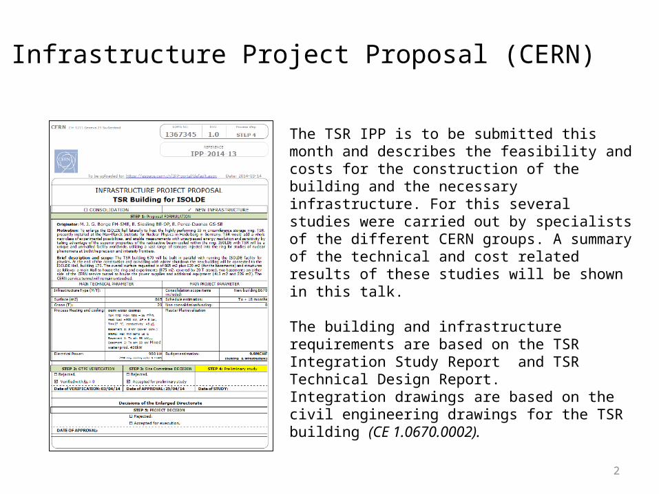
The TSR IPP is to be submitted this month and describes the feasibility and costs for the construction of the building and the necessary infrastructure. For this several studies were carried out by specialists of the different CERN groups. A summary of the technical and cost related results of these studies will be shown in this talk.
The building and infrastructure requirements are based on the TSR Integration Study Report and TSR Technical Design Report.Integration drawings are based on the civil engineering drawings for the TSR building (CE 1.0670.0002).
3
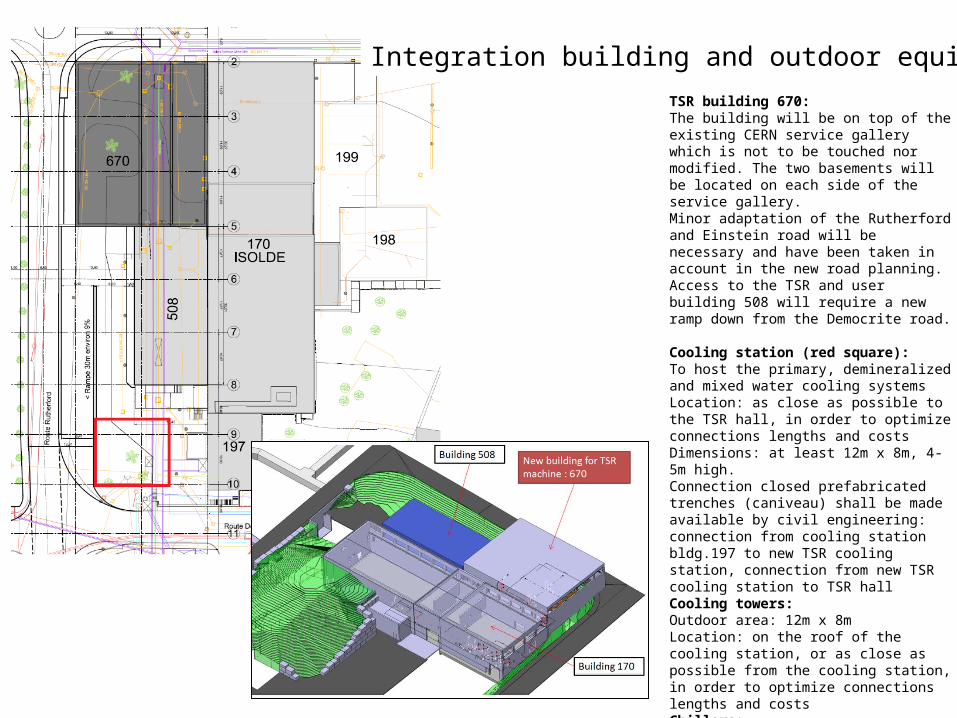
TSR building 670:The building will be on top of the existing CERN service gallery which is not to be touched nor modified. The two basements will be located on each side of the service gallery.Minor adaptation of the Rutherford and Einstein road will be necessary and have been taken in account in the new road planning.Access to the TSR and user building 508 will require a new ramp down from the Democrite road.
Cooling station (red square):To host the primary, demineralized and mixed water cooling systemsLocation: as close as possible to the TSR hall, in order to optimize connections lengths and costsDimensions: at least 12m x 8m, 4-5m high. Connection closed prefabricated trenches (caniveau) shall be made available by civil engineering: connection from cooling station bldg.197 to new TSR cooling station, connection from new TSR cooling station to TSR hallCooling towers:Outdoor area: 12m x 8mLocation: on the roof of the cooling station, or as close as possible from the cooling station, in order to optimize connections lengths and costsChillers:Outdoor area: 5m x 8mconcrete slab at ground level or grating metal structure on a roof (bldg.197 to be checked)Location: as close as possible from the cooling station, in order to optimize connections lengths and costs
Integration building and outdoor equipment
4
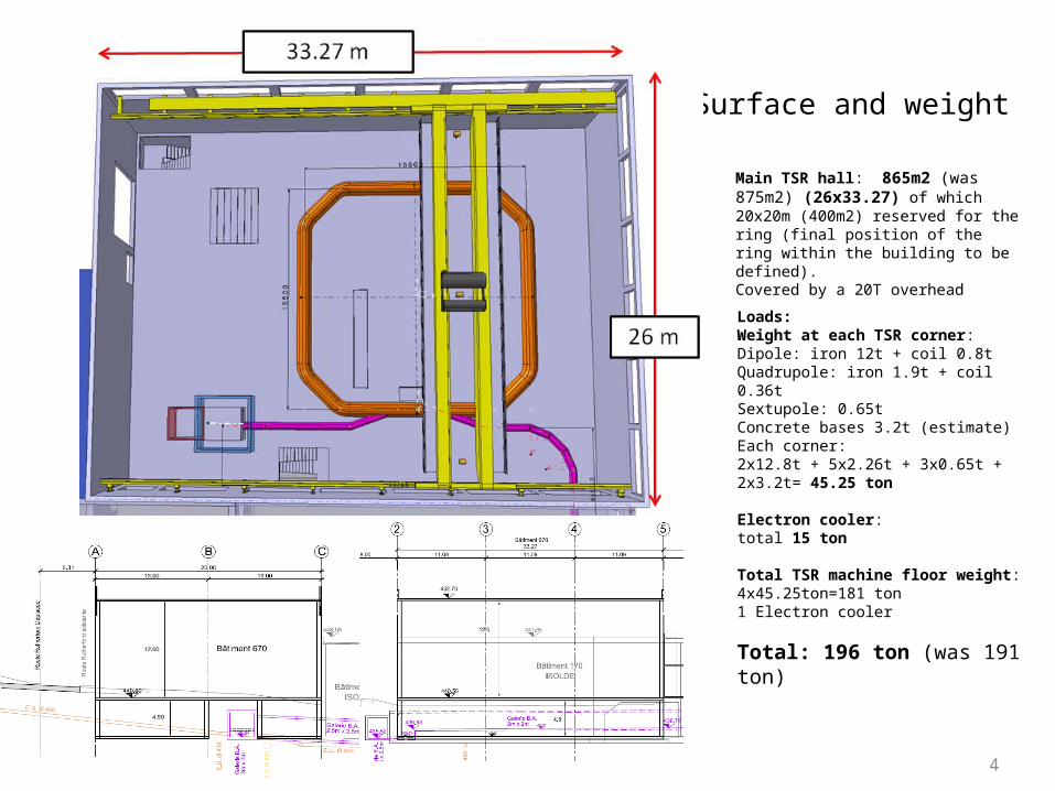
Main TSR hall: 865m2 (was 875m2) (26x33.27) of which 20x20m (400m2) reserved for the ring (final position of the ring within the building to be defined).Covered by a 20T overhead crane.
Loads:Weight at each TSR corner:Dipole: iron 12t + coil 0.8tQuadrupole: iron 1.9t + coil 0.36tSextupole: 0.65tConcrete bases 3.2t (estimate)Each corner:2x12.8t + 5x2.26t + 3x0.65t + 2x3.2t= 45.25 ton Electron cooler:total 15 ton Total TSR machine floor weight:4x45.25ton=181 ton1 Electron cooler
Total: 196 ton (was 191 ton)
Surface and weight
5
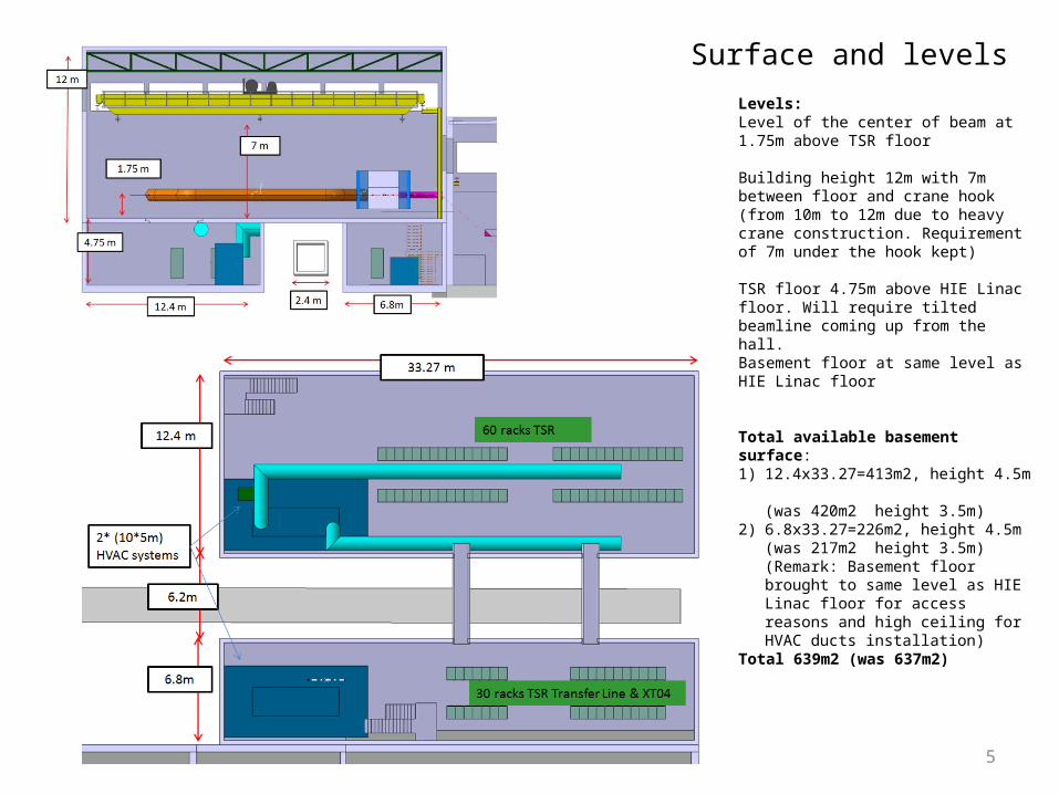
Levels:Level of the center of beam at 1.75m above TSR floor
Building height 12m with 7m between floor and crane hook (from 10m to 12m due to heavy crane construction. Requirement of 7m under the hook kept)
TSR floor 4.75m above HIE Linac floor. Will require tilted beamline coming up from the hall.Basement floor at same level as HIE Linac floor
Total available basement surface:1) 12.4x33.27=413m2, height 4.5m
(was 420m2 height 3.5m)2) 6.8x33.27=226m2, height 4.5m
(was 217m2 height 3.5m)(Remark: Basement floor brought to same level as HIE Linac floor for access reasons and high ceiling for HVAC ducts installation)
Total 639m2 (was 637m2)
Surface and levels
6
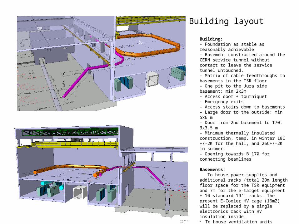
Building layout
Building:- Foundation as stable as reasonably achievable- Basement constructed around the CERN service tunnel without contact to leave the service tunnel untouched. - Matrix of cable feedthroughs to basements in the TSR floor- One pit to the Jura side basement: min 2x3m- Access door + tourniquet- Emergency exits- Access stairs down to basements- Large door to the outside: min 5x6 m- Door from 2nd basement to 170: 3x3.5 m- Minimum thermally insulated construction, temp. in winter 18C +/-2K for the hall, and 26C+/-2K in summer.- Opening towards B 170 for connecting beamlines
Basements:- To house power-supplies and additional racks (total 29m length floor space for the TSR equipment and 7m for the e-target equipment + 10 standard 19’’ racks. The present E-Cooler HV cage (16m2) will be replaced by a single electronics rack with HV insulation inside.- To house ventilation units- To house the transfer line and XT04 line power
supplies
7
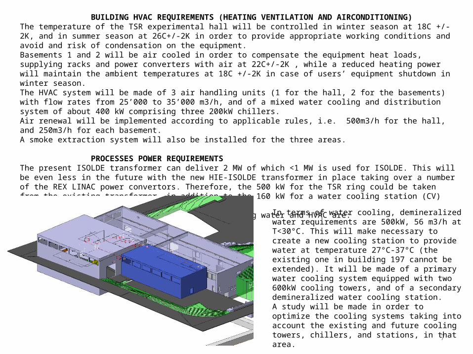
BUILDING HVAC REQUIREMENTS (HEATING VENTILATION AND AIRCONDITIONING)The temperature of the TSR experimental hall will be controlled in winter season at 18C +/-2K, and in summer season at 26C+/-2K in order to provide appropriate working conditions and avoid and risk of condensation on the equipment. Basements 1 and 2 will be air cooled in order to compensate the equipment heat loads, supplying racks and power converters with air at 22C+/-2K , while a reduced heating power will maintain the ambient temperatures at 18C +/-2K in case of users’ equipment shutdown in winter season.The HVAC system will be made of 3 air handling units (1 for the hall, 2 for the basements) with flow rates from 25’000 to 35’000 m3/h, and of a mixed water cooling and distribution system of about 400 kW comprising three 200kW chillers. Air renewal will be implemented according to applicable rules, i.e. 500m3/h for the hall, and 250m3/h for each basement.A smoke extraction system will also be installed for the three areas.
PROCESSES POWER REQUIREMENTSThe present ISOLDE transformer can deliver 2 MW of which <1 MW is used for ISOLDE. This will be even less in the future with the new HIE-ISOLDE transformer in place taking over a number of the REX LINAC power convertors. Therefore, the 500 kW for the TSR ring could be taken from the existing transformer, in addition to the 160 kW for a water cooling station (CV) and 320 kW for ventilation.The requirements for the Electrical power, Cooling water and HVAC are:TSR ring: 500 kWWater cooling station: 160 kWHVAC system: 320 kW
In terms of water cooling, demineralized water requirements are 500kW, 56 m3/h at T<30°C. This will make necessary to create a new cooling station to provide water at temperature 27°C-37°C (the existing one in building 197 cannot be extended). It will be made of a primary water cooling system equipped with two 600kW cooling towers, and of a secondary demineralized water cooling station.A study will be made in order to optimize the cooling systems taking into account the existing and future cooling towers, chillers, and stations, in that area.
8
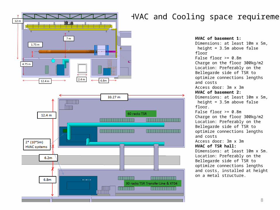
HVAC of basement 1:Dimensions: at least 10m x 5m, height = 3.5m above false floor False floor >= 0.8m Charge on the floor 300kg/m2Location: Preferably on the Bellegarde side of TSR to optimize connections lengths and costsAccess door: 3m x 3m HVAC of basement 2:Dimensions: at least 10m x 5m, height = 3.5m above false floor.False floor >= 0.8m Charge on the floor 300kg/m2Location: Preferably on the Bellegarde side of TSR to optimize connections lengths and costsAccess door: 3m x 3m HVAC of TSR hall:Dimensions: at least 10m x 5m.Location: Preferably on the Bellegarde side of TSR to optimize connections lengths and costs, installed at height on a metal structure.
HVAC and Cooling space requirements
9
Overall project schedule
CIVIL ENGINEERING SCHEDULEStudy (2 mnts), Market survey (6 wks), preparations specs (2 mnts), call for tender (1 month), preparations contractor (2 mnts) – with some actions overlapping about 8 mnts.Aim to reach the Finance Committee in December 2015 -> contract signature January 2016 and start construction February 2016.For the building one should count 9 months due to the complexity of the basements / service tunnel.
TECHNICAL INFRASTRUCTURE SCHEDULE The typical CV schedule for such a project is: 12 months for design and tendering12 months for installation works and commissioning
Writing of the specifications for the different systems, the integration and the tendering process will be handled by the different CERN groups. The actual fabrication and installation of the systems however will be in the hands of the selected contractors.
10
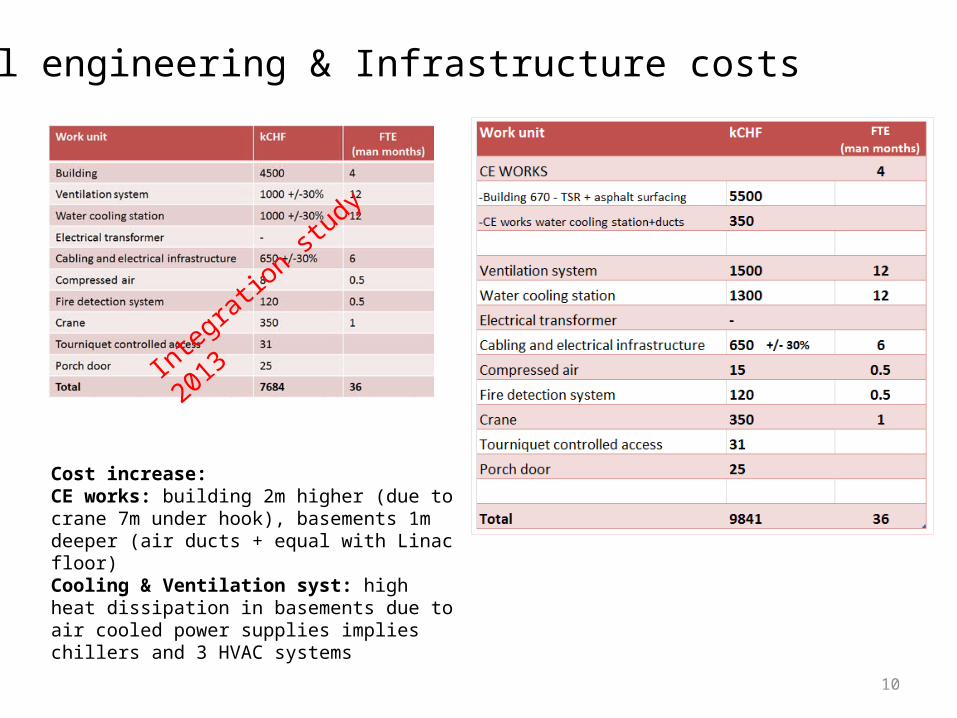
Civil engineering & Infrastructure costs
Cost increase:CE works: building 2m higher (due to crane 7m under hook), basements 1m deeper (air ducts + equal with Linac floor)Cooling & Ventilation syst: high heat dissipation in basements due to air cooled power supplies implies chillers and 3 HVAC systems
Integration study 2013

11
Acknowledgement
• MPIK : MANFRED GRIESER• GS/SE : ELISEO PERES-DUENAZ• EN/MEF : STEPHANE MARIDOR• BE/ABP : FREDERIK WENANDER • PH/SME : MARIA BORGE• EN/CV : PAUL PEPINSTER• EN/EL : RENE NECCA, JEAN-CLAUDE GUILLAUME, GEORGI GEORGIEV• EN/HE : CATERINA BERTONE