Embed Size (px)
Citation preview
資料-00
Steam TrapSteam TrapAssist TrapRadiator TrapRadiator Valve
219
P219-220_扉_スチームトラップ 2011.3.10 10:07 PM ページ 1
資料-00
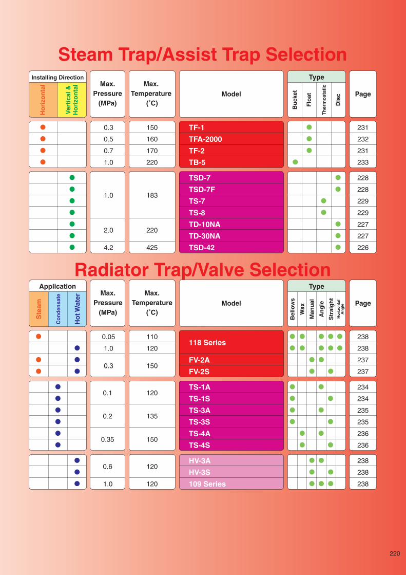
Steam Trap/Assist Trap Selection
●
●
●
●
�
�
�
●
●
●�
●�
0.3
0.5
0.7
1.0
150
160
170
220
231
232
231
233
TF-1
TFA-2000
TF-2
TB-5
●
●
●
●
●
●
●
�
�
●�
●�
●�
●�
�
�
●�
●�
●�
1.0
2.0
4.2
183
220
425
228
228
229
229
227
227
226
TSD-7
TSD-7F
TS-7
TS-8
TD-10NA
TD-30NA
TSD-42
Installing Direction
Ho
rizo
nta
l
Ver
tica
l &H
ori
zon
tal
Type
Bu
cket
Flo
at
Th
erm
ost
atic
Dis
c
Max.Pressure
(MPa)
Max.Temperature
(˚C)Model Page
●
�
●
●�
�
●�
●�
●�
� ●�
●
●
●�
�
�
●�●�
●�
●�
●�
●
●�
0.05
1.0
0.3
110
120
150
238
238
237
237
118 Series
FV-2A
FV-2S
�
�
�
�
●
●
●�
�
�
�
�
� �●
●�
●�
●
�
●�
●�
●�
�0.6
1.0
120
120
238
238
238
HV-3A
HV-3S
109 Series
●�
●�
●�
●�
●�
●�
�
�
�
�
�
●�
●�
●�
●�
�
�
�
�
●
●
●
�
●�
●
●�
●�
�
●�
�
●
�
●
●�
�0.1
0.2
0.35
120
135
150
234
234
235
235
236
236
TS-1A
TS-1S
TS-3A
TS-3S
TS-4A
TS-4S
Application
Ste
am
Ho
t Wat
er
Co
nd
ensa
te
TypeB
ello
ws
Wax
Man
ual
An
gle
Str
aig
ht
Ho
rizo
nta
lA
ng
le
Max.Pressure
(MPa)
Max.Temperature
(˚C)Model Page
220
Radiator Trap/Valve Selection
P219-220_扉_スチームトラップ 2011.3.10 10:07 PM ページ 2
S t e a m T r a p
Ste
am T
rap
Ste
am T
rap
7-3, Futano-cho, Mizuho-ku, Nagoya, 467-0861, Japan Phone: 81-52-881-7199 Fax: 81-52-881-7201
www.yoshitake.jp221
トラ-00
Selection of Steam Trap
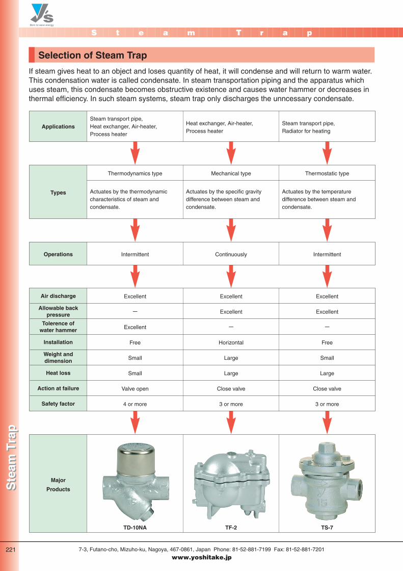
If steam gives heat to an object and loses quantity of heat, it will condense and will return to warm water.This condensation water is called condensate. In steam transportation piping and the apparatus whichuses steam, this condensate becomes obstructive existence and causes water hammer or decreases inthermal efficiency. In such steam systems, steam trap only discharges the unncessary condensate.
Thermodynamics type Mechanical type Thermostatic type
Steam transport pipe, Heat exchanger, Air-heater, Process heater
Steam transport pipe, Radiator for heating
Heat exchanger, Air-heater, Process heater
Excellent
-
Excellent
Free
Small
Small
Valve open
4 or more
Excellent
Excellent
-
Horizontal
Large
Large
Close valve
3 or more
Excellent
Excellent
-
Free
Small
Large
Close valve
3 or more
Air discharge
Allowable backpressure
Tolerence ofwater hammer
Installation
Weight anddimension
Heat loss
Action at failure
Safety factor
TD-10NA TF-2 TS-7
Applications
Intermittent Continuously IntermittentOperations
Actuates by the thermodynamic characteristics of steam and condensate.
Actuates by the temperature difference between steam and condensate.
Actuates by the specific gravity difference between steam and condensate.
Types
Major
Products
P221-222_スチ 2011.3.10 10:08 PM ページ 1
S t e a m T r a p
Ste
am T
rap
Ste
am T
rap
7-3, Futano-cho, Mizuho-ku, Nagoya, 467-0861, Japan Phone: 81-52-881-7199 Fax: 81-52-881-7201
www.yoshitake.jp222
トラ-14
Note for Selecting Steam Trap
There are various kinds of steam trap classified by operation, discharge capacity, etc. In order to obtainthe full benefit from the traps, selecting proper trap size and pressure is essential. The followings areconsiderations to select the proper traps.
1: Service pointEach service point has each requirements for steam traps. Please consider the following points to selectthe proper traps.Steam piping / Header・Not affected by outside temperature ・Air discharge at the starting system ・Small steam lossAt the end of piping・Discharges mass volume at the starting・Continuous blow ・Air discharge at the starting system Equipment / process・Operates under fluctuation of condensate volume ・High back pressure operation・Air discharge at the starting system ・No accumulation of condensate at the time of failure
4: Differential pressureBecause of operation, allowable back pressure is less than 50% of inlet pressure for thermodynamicstype. On thermostatic and float type, back pressure has no adverse effect on operation, but as backpressure approaches to inlet pressure, discharge becomes less since differential pressure will be low.
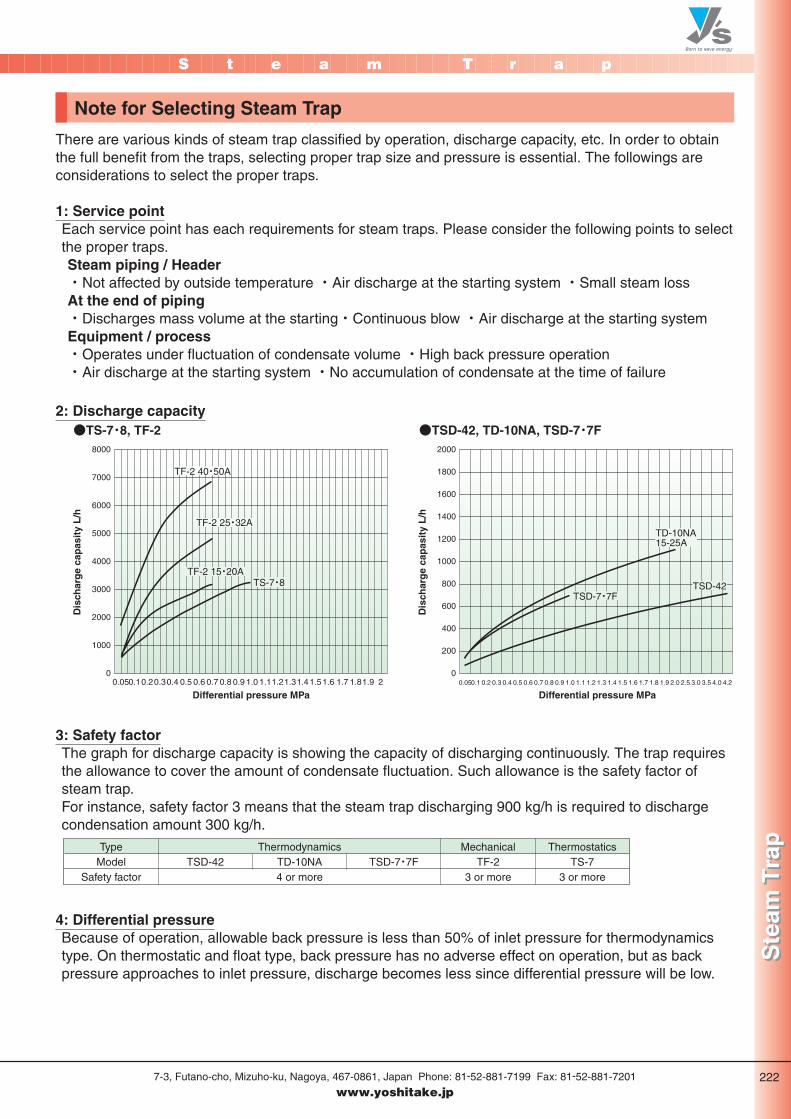
2: Discharge capacity●TS-7・8, TF-2 ●TSD-42, TD-10NA, TSD-7・7F
Differential pressure MPa
8000
7000
6000
5000
4000
3000
2000
1000
0
2000
1800
1600
1400
1200
1000
800
600
400
200
0
Dis
char
ge
cap
asit
y L
/h
Differential pressure MPa
Dis
char
ge
cap
asit
y L
/h
0.05 0.050.1 0.2 0.3 0.4 0.5 0.6 0.7 0.8 0.9 1.0 1.1 1.2 1.3 1.4 1.5 1.6 1.7 1.8 1.9 2.0 2.5 3.0 3.5 4.0 4.20.10.20.30.4 0.5 0.6 0.7 0.8 0.9 1.0 1.11.21.31.41.51.6 1.7 1.81.9 2
TF-2 40・50A
TF-2 25・32A
TF-2 15・20ATS-7・8
TSD-7・7F
TD-10NA15-25A
TSD-42
3: Safety factorThe graph for discharge capacity is showing the capacity of discharging continuously. The trap requiresthe allowance to cover the amount of condensate fluctuation. Such allowance is the safety factor ofsteam trap.For instance, safety factor 3 means that the steam trap discharging 900 kg/h is required to dischargecondensation amount 300 kg/h.
TypeModel
Safety factor
ThermodynamicsTD-10NA4 or more
TSD-42 TSD-7・7FThermostatics
TS-73 or more
MechanicalTF-2
3 or more
P221-222_スチ 2011.3.10 10:08 PM ページ 2
S t e a m T r a p
Ste
am T
rap
Ste
am T
rap
7-3, Futano-cho, Mizuho-ku, Nagoya, 467-0861, Japan Phone: 81-52-881-7199 Fax: 81-52-881-7201
www.yoshitake.jp223
トラ-15
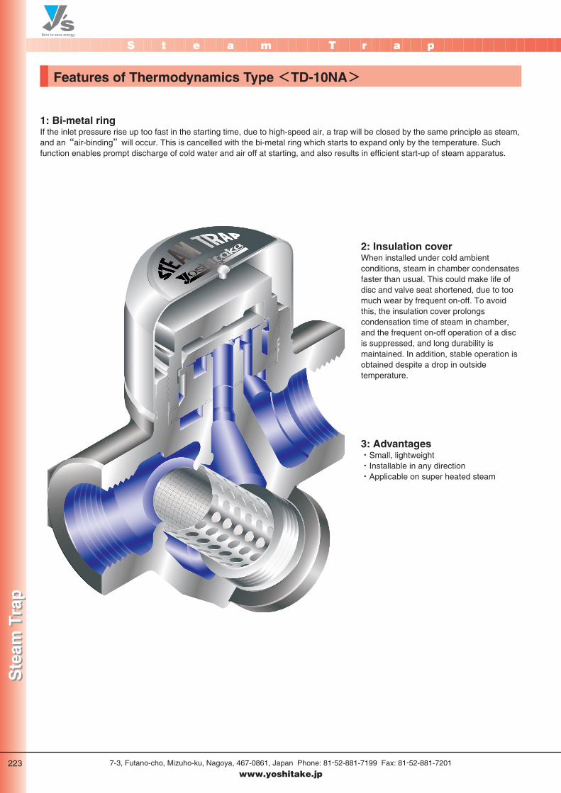
Features of Thermodynamics Type <TD-10NA>
2: Insulation coverWhen installed under cold ambientconditions, steam in chamber condensatesfaster than usual. This could make life ofdisc and valve seat shortened, due to toomuch wear by frequent on-off. To avoidthis, the insulation cover prolongscondensation time of steam in chamber,and the frequent on-off operation of a discis suppressed, and long durability ismaintained. In addition, stable operation isobtained despite a drop in outsidetemperature.
3: Advantages・Small, lightweight・Installable in any direction・Applicable on super heated steam
1: Bi-metal ringIf the inlet pressure rise up too fast in the starting time, due to high-speed air, a trap will be closed by the same principle as steam,and an“air-binding”will occur. This is cancelled with the bi-metal ring which starts to expand only by the temperature. Suchfunction enables prompt discharge of cold water and air off at starting, and also results in efficient start-up of steam apparatus.
P223-224_スチ 2011.3.10 10:18 PM ページ 1
S t e a m T r a p
Ste
am T
rap
Ste
am T
rap
7-3, Futano-cho, Mizuho-ku, Nagoya, 467-0861, Japan Phone: 81-52-881-7199 Fax: 81-52-881-7201
www.yoshitake.jp224
トラ-16
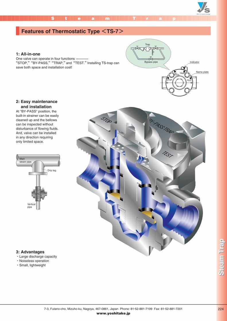
Features of Thermostatic Type <TS-7>
1: All-in-oneOne valve can operate in four functions “STOP,”“BY-PASS,”“TRAP,”and“TEST.”Installing TS-trap cansave both space and installation cost!
2: Easy maintenanceand installation
At ''BY-PASS'' position, thebuilt-in strainer can be easilycleaned up and the bellowscan be inspected withoutdisturbance of flowing fluids.And, valve can be installedin any direction requiringonly limited space.
3: Advantages・Large discharge capacity・Noiseless operation・Small, lightweight
TEST
BY-PASS
TRAP
STOP
Trap
Bypass pipe Indicator
Name plate
Main steam pipe
Drip leg
Verticalpipe
P223-224_スチ 2011.3.10 10:18 PM ページ 2
S t e a m T r a p
Ste
am T
rap
Ste
am T
rap
7-3, Futano-cho, Mizuho-ku, Nagoya, 467-0861, Japan Phone: 81-52-881-7199 Fax: 81-52-881-7201
www.yoshitake.jp225
トラ-17
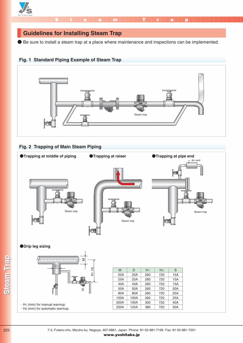
Guidelines for Installing Steam Trap● Be sure to install a steam trap at a place where maintenance and inspections can be implemented.
Fig. 1 Standard Piping Example of Steam Trap
Fig. 2 Trapping of Main Steam Piping
D
H1,
H2
M
S
D
Steam trap
●Trapping at middle of piping
●Drip leg sizing
●Trapping at raiser ●Trapping at pipe endAir vent
・H1 (mm) for manual warmup・H2 (mm) for automatic warmup
M20A25A40A50A80A
100A200A250A
D20A25A40A50A80A
100A100A125A
H1
260260260260260260300380
H2
720720720720720720720720
S15A15A15A20A25A25A40A50A
Steam trap
Steam trap
Steam trap
P225_スチ 2011.3.10 10:19 PM ページ 1
SteamSteamA i r
A i rWaterWater
S t e a m T r a p
Ste
am T
rap
Ste
am T
rap
7-3, Futano-cho, Mizuho-ku, Nagoya, 467-0861, Japan Phone: 81-52-881-7199 Fax: 81-52-881-7201
www.yoshitake.jp226
トラ-00
Disc type Ductile iron
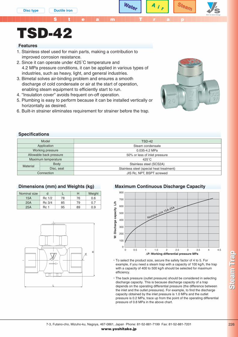
TSD-42Features
1. Stainless steel used for main parts, making a contribution toimproved corrosion resistance.
2. Since it can operate under 425˚C temperature and 4.2 MPa pressure conditions, it can be applied in various types ofindustries, such as heavy, light, and general industries.
3. Bimetal solves air-binding problem and ensures a smoothdischarge of cold condensate or air at the start of operation,enabling steam equipment to efficiently start to run.
4. ''Insulation cover'' avoids frequent on-off operation.5. Plumbing is easy to perform because it can be installed vertically or
horizontally as desired.6. Built-in strainer eliminates requirement for strainer before the trap.
SpecificationsTSD-42
Steam condensate0.035-4.2 MPa
50% or less of inlet pressure425˚C
Stainless steel (SCS2A)Stainless steel (special heat treatment)
JIS Rc, NPT, BSPT screwed
ModelApplication
Working pressureAllowable back pressureMaximum temperature
BodyDisc, seat
Connection
Material
Nominal size H WeightL0.60.70.9
15A20A25A
767989
788595
dRc 1/2Rc 3/4Rc 1
L
H
d
0
100
200
300
400
500
600
700
800
0.50 1 1.5 2 2.5 3 3.5 4 4.5
W: D
isch
arg
e ca
pac
ity
L/h
∆P: Working differential pressure MPa
Nominal size 15A-25A
Dimensions (mm) and Weights (kg) Maximum Continuous Discharge Capacity
・ To select the product size, secure the safety factor of 4 to 5. Forexample, if you need a steam trap with a capacity of 100 kg/h, the trapwith a capacity of 400 to 500 kg/h should be selected for maximumefficiency.
・ The back pressure (outlet pressure) should be considered in selectingdischarge capacity. This is because discharge capacity of a trapdepends on the operating differential pressure (the difference betweenthe inlet and the outlet pressures). For example, to find the dischargecapacity obtained by the inlet pressure is 1.0 MPa and the outletpressure is 0.2 MPa, trace up from the point of the operating differentialpressure of 0.8 MPa in the above chart.
P226_スチ 2011.3.10 10:19 PM ページ 1
S t e a m T r a p
Ste
am T
rap
Ste
am T
rap
7-3, Futano-cho, Mizuho-ku, Nagoya, 467-0861, Japan Phone: 81-52-881-7199 Fax: 81-52-881-7201
www.yoshitake.jp227
トラ-00
SteamSteam
Disc type Ductile iron
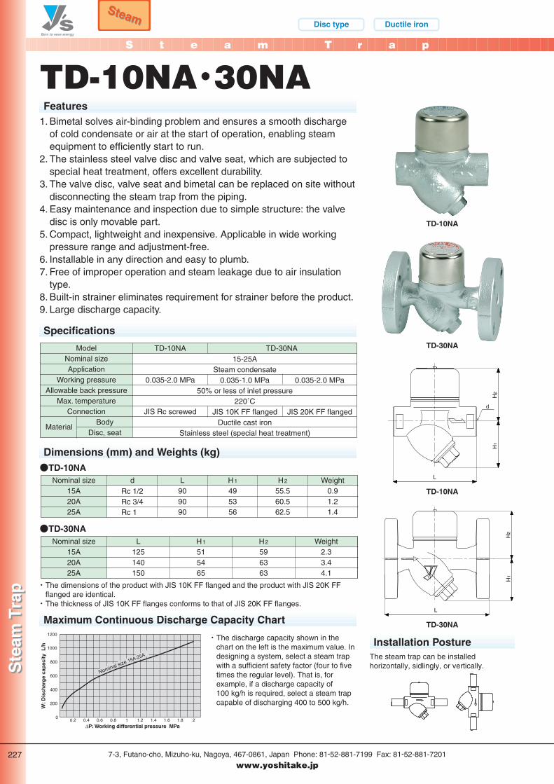
TD-10NA・30NAFeatures
TD-10NA
d
TD-30NA
TD-10NA
TD-30NA
Installation Posture
Maximum Continuous Discharge Capacity Chart
The steam trap can be installedhorizontally, sidlingly, or vertically.
Specifications
TD-10NA
0.035-2.0 MPa
JIS Rc screwed
TD-30NA15-25A
Steam condensate0.035-1.0 MPa
50% or less of inlet pressure220˚C
JIS 10K FF flangedDuctile cast iron
Stainless steel (special heat treatment)
0.035-2.0 MPa
JIS 20K FF flanged
ModelNominal sizeApplication
Working pressureAllowable back pressure
Max. temperatureConnection
BodyDisc, seat
Material
Nominal size15A20A25A
Weight0.91.21.4
dRc 1/2Rc 3/4Rc 1
L909090
H1
495356
H2
55.560.562.5
Dimensions (mm) and Weights (kg)●TD-10NA
Nominal size15A20A25A
Weight2.33.44.1
L125140150
H1
515465
H2
596363
●TD-30NA
・ The dimensions of the product with JIS 10K FF flanged and the product with JIS 20K FFflanged are identical.・ The thickness of JIS 10K FF flanges conforms to that of JIS 20K FF flanges.
1200
1000
800
600
400
200
00.2 0.4 0.6 0.8 1 1.2 1.4 1.6 1.8 2
Nominal size 15A-25A
W: D
isch
arg
e ca
pac
ity
L/h
∆P: Working differential pressure MPa
・ The discharge capacity shown in thechart on the left is the maximum value. Indesigning a system, select a steam trapwith a sufficient safety factor (four to fivetimes the regular level). That is, forexample, if a discharge capacity of 100 kg/h is required, select a steam trapcapable of discharging 400 to 500 kg/h.
1. Bimetal solves air-binding problem and ensures a smooth dischargeof cold condensate or air at the start of operation, enabling steamequipment to efficiently start to run.
2. The stainless steel valve disc and valve seat, which are subjected tospecial heat treatment, offers excellent durability.
3. The valve disc, valve seat and bimetal can be replaced on site withoutdisconnecting the steam trap from the piping.
4. Easy maintenance and inspection due to simple structure: the valvedisc is only movable part.
5. Compact, lightweight and inexpensive. Applicable in wide workingpressure range and adjustment-free.
6. Installable in any direction and easy to plumb.7. Free of improper operation and steam leakage due to air insulation
type.8. Built-in strainer eliminates requirement for strainer before the product.9. Large discharge capacity.
P227_スチ 2011.3.10 10:20 PM ページ 1
SteamSteamA i r
A i rWaterWater
S t e a m T r a p
Ste
am T
rap
Ste
am T
rap
7-3, Futano-cho, Mizuho-ku, Nagoya, 467-0861, Japan Phone: 81-52-881-7199 Fax: 81-52-881-7201
www.yoshitake.jp228
トラ-00
Disc type Ductile iron
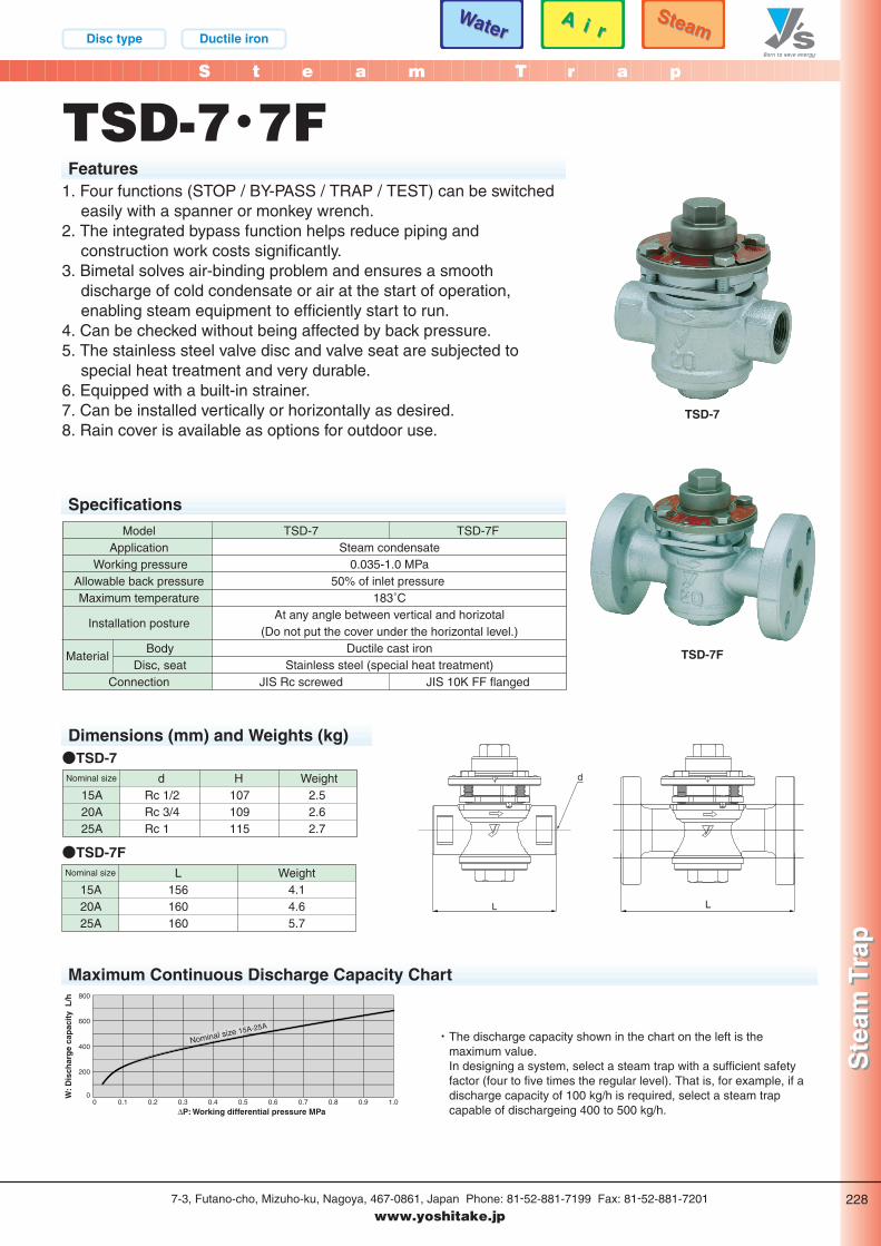
TSD-7・7FFeatures
1. Four functions (STOP / BY-PASS / TRAP / TEST) can be switchedeasily with a spanner or monkey wrench.
2. The integrated bypass function helps reduce piping andconstruction work costs significantly.
3. Bimetal solves air-binding problem and ensures a smoothdischarge of cold condensate or air at the start of operation,enabling steam equipment to efficiently start to run.
4. Can be checked without being affected by back pressure.5. The stainless steel valve disc and valve seat are subjected to
special heat treatment and very durable.6. Equipped with a built-in strainer.7. Can be installed vertically or horizontally as desired.8. Rain cover is available as options for outdoor use.
SpecificationsTSD-7
JIS Rc screwed
ModelApplication
Working pressureAllowable back pressureMaximum temperature
Installation posture
BodyDisc, seat
Connection
TSD-7F
JIS 10K FF flanged
Steam condensate0.035-1.0 MPa
50% of inlet pressure 183˚C
At any angle between vertical and horizotal(Do not put the cover under the horizontal level.)
Ductile cast ironStainless steel (special heat treatment)
Material
Nominal size H Weightd2.52.62.7
15A20A25A
107109115
Rc 1/2Rc 3/4Rc 1
Nominal size WeightL15A20A25A
4.14.65.7
156160160
L
d
L
200
400
600
800
00.10 0.2 0.3 0.4 0.5 0.6 0.7 0.8 0.9 1.0
W: D
isch
arg
e ca
pac
ity
L/h
∆P: Working differential pressure MPa
Nominal size 15A-25A
Dimensions (mm) and Weights (kg)
Maximum Continuous Discharge Capacity Chart
・ The discharge capacity shown in the chart on the left is themaximum value.In designing a system, select a steam trap with a sufficient safetyfactor (four to five times the regular level). That is, for example, if adischarge capacity of 100 kg/h is required, select a steam trapcapable of dischargeing 400 to 500 kg/h.
TSD-7
TSD-7F
●TSD-7
●TSD-7F
P228_スチ 2011.3.10 10:21 PM ページ 1
Bellows Ductile iron
S t e a m T r a p
Ste
am T
rap
Ste
am T
rap
7-3, Futano-cho, Mizuho-ku, Nagoya, 467-0861, Japan Phone: 81-52-881-7199 Fax: 81-52-881-7201
www.yoshitake.jp229
トラ-01
SteamSteam
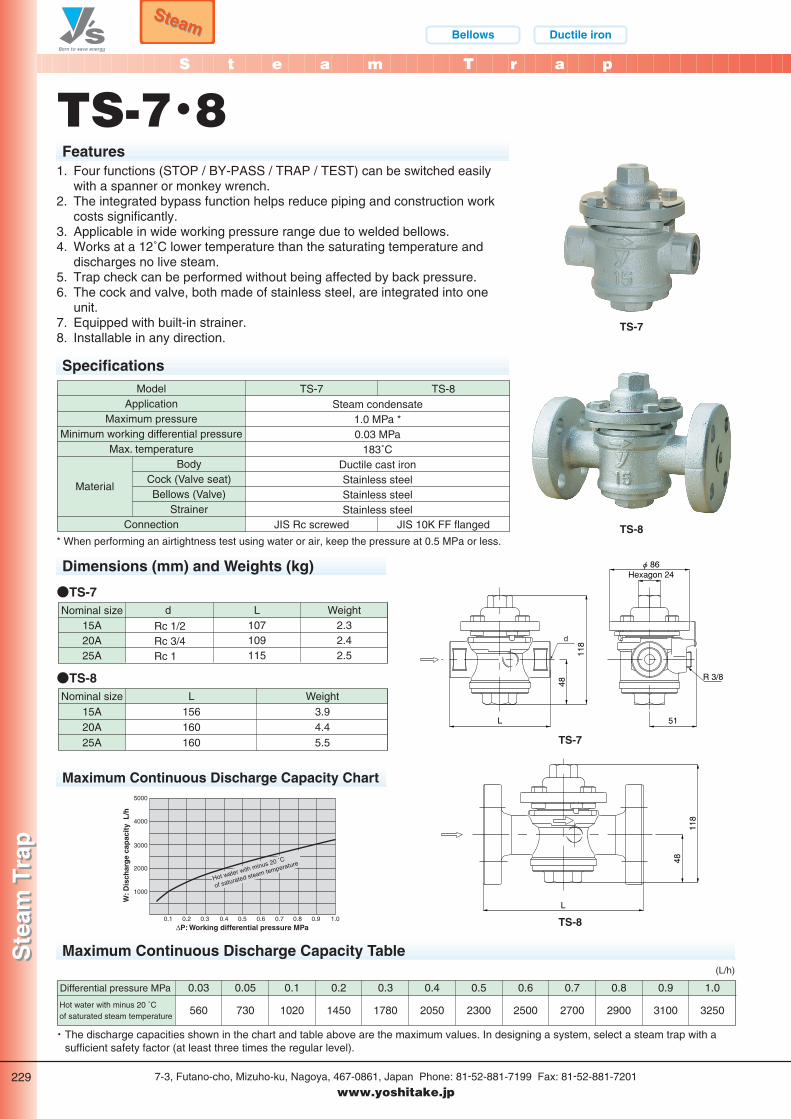
TS-7・8Features
TS-7
L 51
R 3/8
118
48φ 86
Hexagon 24
d
TS-8
TS-7
L
118
48
TS-8
Maximum Continuous Discharge Capacity Chart
SpecificationsTS-7
JIS Rc screwed
TS-8
JIS 10K FF flanged
Steam condensate1.0 MPa *0.03 MPa
183˚CDuctile cast ironStainless steelStainless steelStainless steel
ModelApplication
Maximum pressureMinimum working differential pressure
Max. temperatureBody
Cock (Valve seat)Bellows (Valve)
StrainerConnection
Material
Nominal size15A20A25A
Weight2.32.42.5
d
Rc 1/2Rc 3/4Rc 1
L107109115
Dimensions (mm) and Weights (kg)
●TS-7
Nominal size15A20A25A
Weight3.94.45.5
L156160160
●TS-8
5000
4000
3000
2000
1000
0.1 0.2 0.3 0.4 0.5 0.6 0.7 0.8 0.9 1.0
W: D
isch
arg
e ca
pac
ity
L/h
∆P: Working differential pressure MPa
Hot water with minus 20 ˚C
of saturated steam temperature
1. Four functions (STOP / BY-PASS / TRAP / TEST) can be switched easilywith a spanner or monkey wrench.
2. The integrated bypass function helps reduce piping and construction workcosts significantly.
3. Applicable in wide working pressure range due to welded bellows.4. Works at a 12˚C lower temperature than the saturating temperature and
discharges no live steam.5. Trap check can be performed without being affected by back pressure.6. The cock and valve, both made of stainless steel, are integrated into one
unit.7. Equipped with built-in strainer.8. Installable in any direction.
* When performing an airtightness test using water or air, keep the pressure at 0.5 MPa or less.
Maximum Continuous Discharge Capacity Table
0.03
560
Differential pressure MPa
Hot water with minus 20 ˚Cof saturated steam temperature
0.05
730
0.1
1020
0.2
1450
0.3
1780
0.4
2050
0.5
2300
0.6
2500
0.7
2700
0.8
2900
0.9
3100
1.0
3250
・ The discharge capacities shown in the chart and table above are the maximum values. In designing a system, select a steam trap with asufficient safety factor (at least three times the regular level).
(L/h)
P229-230_スチ 2011.3.10 10:21 PM ページ 1
S t e a m T r a p
Ste
am T
rap
Ste
am T
rap
7-3, Futano-cho, Mizuho-ku, Nagoya, 467-0861, Japan Phone: 81-52-881-7199 Fax: 81-52-881-7201
www.yoshitake.jp230
トラ-02
TS-7・8
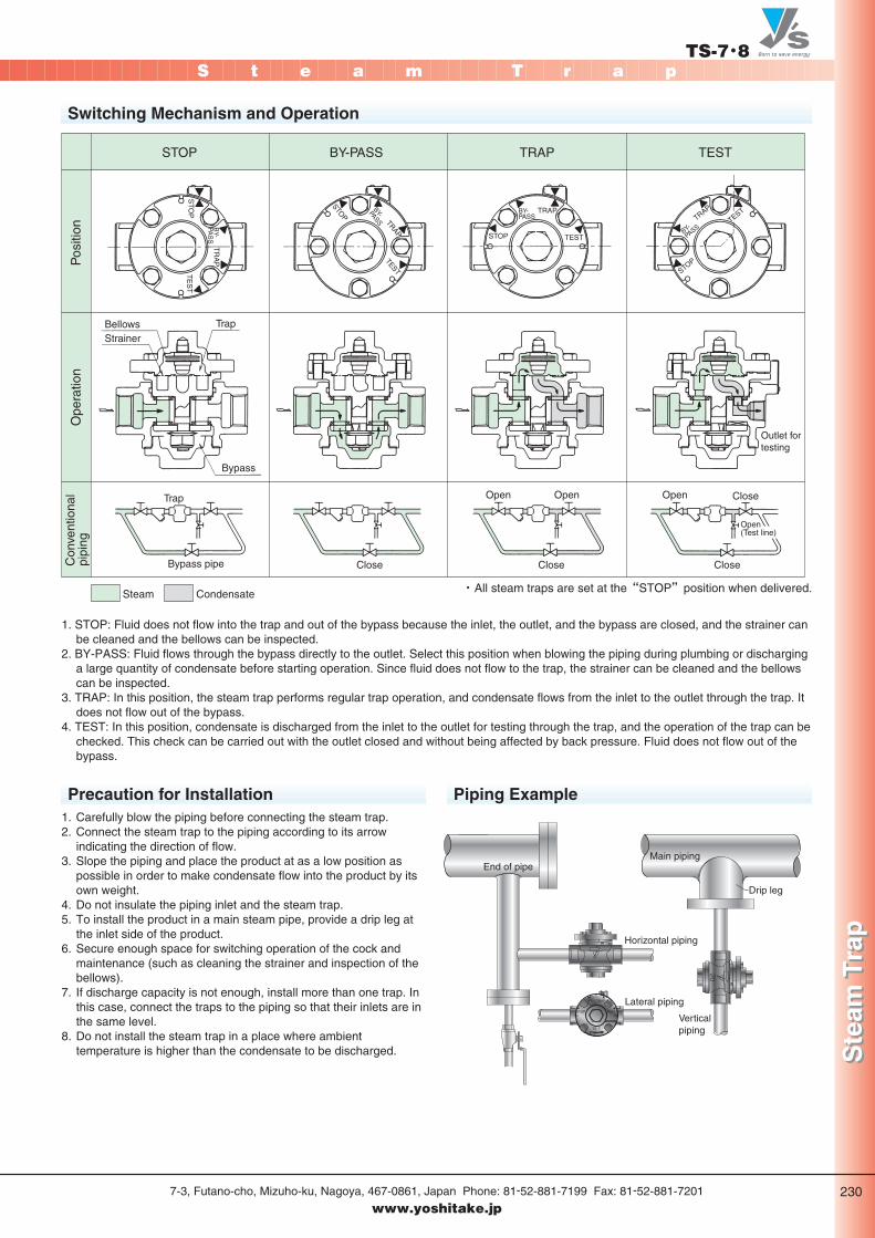
Switching Mechanism and Operation
STO
P
TR
AP
TE
ST
BY-
PAS
S
STOP
TRAPTEST
BY-PASS
TEST
BY-PASS
TRAP
STOP
TEST
BY-
PASS
TRAP
STOP
STOP BY-PASS TRAP TEST
CondensateSteam
Trap
Bypass
TrapBellows
Pos
ition
Con
vent
iona
lpi
ping
Ope
ratio
n
Strainer
Bypass pipe Close Close
Open Open Open
Open(Test line)
Outlet for testing
Close
Close
・ All steam traps are set at the“STOP”position when delivered.
1. STOP: Fluid does not flow into the trap and out of the bypass because the inlet, the outlet, and the bypass are closed, and the strainer canbe cleaned and the bellows can be inspected.
2. BY-PASS: Fluid flows through the bypass directly to the outlet. Select this position when blowing the piping during plumbing or discharginga large quantity of condensate before starting operation. Since fluid does not flow to the trap, the strainer can be cleaned and the bellowscan be inspected.
3. TRAP: In this position, the steam trap performs regular trap operation, and condensate flows from the inlet to the outlet through the trap. Itdoes not flow out of the bypass.
4. TEST: In this position, condensate is discharged from the inlet to the outlet for testing through the trap, and the operation of the trap can bechecked. This check can be carried out with the outlet closed and without being affected by back pressure. Fluid does not flow out of thebypass.
1. Carefully blow the piping before connecting the steam trap.2. Connect the steam trap to the piping according to its arrow
indicating the direction of flow.3. Slope the piping and place the product at as a low position as
possible in order to make condensate flow into the product by itsown weight.
4. Do not insulate the piping inlet and the steam trap.5. To install the product in a main steam pipe, provide a drip leg at
the inlet side of the product.6. Secure enough space for switching operation of the cock and
maintenance (such as cleaning the strainer and inspection of thebellows).
7. If discharge capacity is not enough, install more than one trap. Inthis case, connect the traps to the piping so that their inlets are inthe same level.
8. Do not install the steam trap in a place where ambienttemperature is higher than the condensate to be discharged.
Precaution for Installation Piping Example
Main piping
Horizontal piping
Lateral piping
End of pipe
Drip leg
Vertical piping
P229-230_スチ 2011.3.10 10:21 PM ページ 2
S t e a m T r a p
7-3, Futano-cho, Mizuho-ku, Nagoya, 467-0861, Japan Phone: 81-52-881-7199 Fax: 81-52-881-7201
www.yoshitake.jp
SteamSteam
Float type Ductile iron
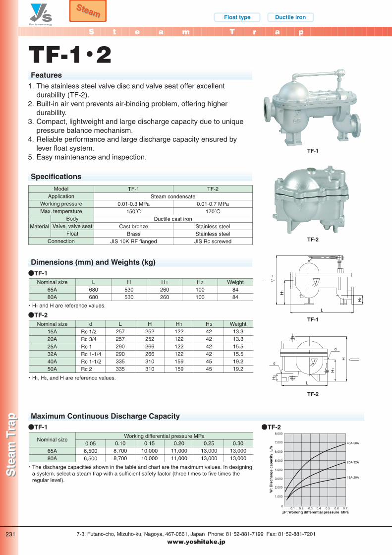
TF-1・2Features
TF-1
H
H1
L
H2
TF-2
TF-1
H
H1
L
H2
d
d
8,000
7,000
6,000
5,000
2,000
1,000
3,000
4,000
00.1 0.2 0.3 0.4 0.5 0.6 0.7
W: D
isch
arg
e ca
pac
ity
L/h
∆P: Working differential pressure MPa
40A-50A
25A-32A
15A-20A
TF-2
Specifications
TF-1
0.01-0.3 MPa150˚C
Cast bronzeBrass
JIS 10K RF flanged
ModelApplication
Working pressureMax. temperature
BodyValve, valve seat
FloatConnection
TF-2
0.01-0.7 MPa170˚C
Stainless steelStainless steelJIS Rc screwed
Material
Steam condensate
Ductile cast iron
Nominal size65A80A
Weight8484
H530530
L680680
H1
260260
H2
100100
Dimensions (mm) and Weights (kg)●TF-1
Nominal size15A20A25A32A40A50A
Weight13.313.315.515.519.219.2
dRc 1/2Rc 3/4Rc 1Rc 1-1/4Rc 1-1/2Rc 2
L257257290290335335
H1
122122122122159159
H252252266266310310
H2
424242424545
●TF-2
・ H1, H2, and H are reference values.
・ H1 and H are reference values.
65A80A
Nominal size0.05
6,5006,500
0.108,7008,700
0.2011,00011,000
0.1510,00010,000
Working differential pressure MPa0.25
13,00013,000
0.3013,00013,000
Maximum Continuous Discharge Capacity●TF-1
・ The discharge capacities shown in the table and chart are the maximum values. In designinga system, select a steam trap with a sufficient safety factor (three times to five times theregular level).
1. The stainless steel valve disc and valve seat offer excellentdurability (TF-2).
2. Built-in air vent prevents air-binding problem, offering higherdurability.
3. Compact, lightweight and large discharge capacity due to uniquepressure balance mechanism.
4. Reliable performance and large discharge capacity ensured bylever float system.
5. Easy maintenance and inspection.
●TF-2
Ste
am T
rap
Ste
am T
rap
231
トラ-03
P231-232_スチ 2011.3.10 10:22 PM ページ 1
155
204
284
40
Condensateinlet
Exhaust port
Driving pressure inlet
Condensateoutlet
140
286
299
62
Holes 2-φ15
Driving pressure - back pressure MPa
80
100
120
140
160
180
0.10 0.2 0.3 0.4 0.5
Dis
char
ge
cap
acit
y k
g/h
Float type Ductile iron
SteamSteam
A s s i s t T r a p
Ass
ist
Tra
pA
ssis
t T
rap
7-3, Futano-cho, Mizuho-ku, Nagoya, 467-0861, Japan Phone: 81-52-881-7199 Fax: 81-52-881-7201
www.yoshitake.jp232
トラ-04
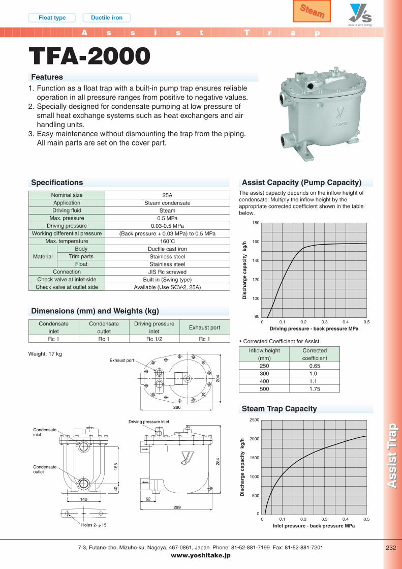
TFA-2000Features
1. Function as a float trap with a built-in pump trap ensures reliableoperation in all pressure ranges from positive to negative values.
2. Specially designed for condensate pumping at low pressure ofsmall heat exchange systems such as heat exchangers and airhandling units.
3. Easy maintenance without dismounting the trap from the piping.All main parts are set on the cover part.
Specifications Assist Capacity (Pump Capacity)
25ASteam condensate
Steam0.5 MPa
0.03-0.5 MPa(Back pressure + 0.03 MPa) to 0.5 MPa
160˚CDuctile cast ironStainless steelStainless steelJIS Rc screwed
Built in (Swing type)Available (Use SCV-2, 25A)
Nominal sizeApplicationDriving fluid
Max. pressureDriving pressure
Working differential pressureMax. temperature
BodyTrim parts
FloatConnection
Check valve at inlet sideCheck valve at outlet side
Material
Dimensions (mm) and Weights (kg)
CondensateinletRc 1
CondensateoutletRc 1
Driving pressureinlet
Rc 1/2
Exhaust port
Rc 1
Weight: 17 kg
The assist capacity depends on the inflow height ofcondensate. Multiply the inflow height by theappropriate corrected coefficient shown in the tablebelow.
Inflow height(mm)250300400500
Correctedcoefficient
0.651.0 1.1 1.75
Steam Trap Capacity
・ Corrected Coefficient for Assist
Inlet pressure - back pressure MPa
0
500
1000
1500
2000
2500
0.10 0.2 0.3 0.4 0.5
Dis
char
ge
cap
acit
y k
g/h
P231-232_スチ 2011.3.10 10:22 PM ページ 2
Bucket Ductile iron
S t e a m T r a p
7-3, Futano-cho, Mizuho-ku, Nagoya, 467-0861, Japan Phone: 81-52-881-7199 Fax: 81-52-881-7201
www.yoshitake.jp
SteamSteam
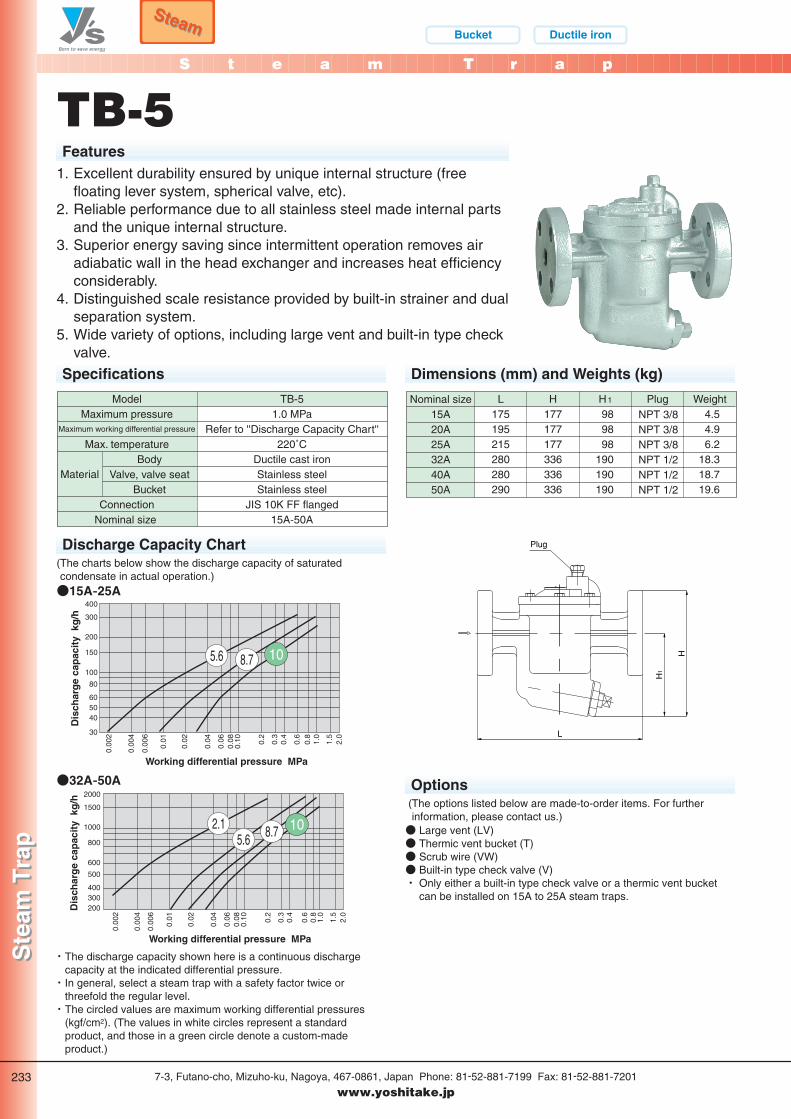
TB-5Features
Discharge Capacity Chart
・ The discharge capacity shown here is a continuous dischargecapacity at the indicated differential pressure.・ In general, select a steam trap with a safety factor twice or
threefold the regular level.・ The circled values are maximum working differential pressures
(kgf/cm2). (The values in white circles represent a standardproduct, and those in a green circle denote a custom-madeproduct.)
Specifications
TB-51.0 MPa
Refer to ''Discharge Capacity Chart''220˚C
Ductile cast ironStainless steelStainless steel
JIS 10K FF flanged15A-50A
ModelMaximum pressure
Maximum working differential pressure
Max. temperatureBody
Valve, valve seatBucket
ConnectionNominal size
Material
400
300
200
150
100
80
30
0.00
2
0.00
4
0.00
6
0.01
0.02
0.04
0.06
0.08
0.10 0.2
0.3
0.4
0.6
0.8
1.0
1.5
2.0
405060
5.6 8.7 10
Working differential pressure MPa
Dis
char
ge
cap
acit
y k
g/h
1. Excellent durability ensured by unique internal structure (freefloating lever system, spherical valve, etc).
2. Reliable performance due to all stainless steel made internal partsand the unique internal structure.
3. Superior energy saving since intermittent operation removes airadiabatic wall in the head exchanger and increases heat efficiencyconsiderably.
4. Distinguished scale resistance provided by built-in strainer and dualseparation system.
5. Wide variety of options, including large vent and built-in type checkvalve.
●15A-25A
2000
1500
1000
800
600
500
0.00
2
0.00
4
0.00
6
0.01
0.02
0.04
0.06
0.08
0.10 0.2
0.3
0.4
0.6
0.8
1.0
1.5
2.0
200300400
2.15.6 8.7 10
Working differential pressure MPa
Dis
char
ge
cap
acit
y k
g/h
●32A-50A
Nominal size15A20A25A32A40A50A
L175195215280280290
NPT 3/8NPT 3/8NPT 3/8NPT 1/2NPT 1/2NPT 1/2
H1 Plug WeightH177177177336336336
989898
190190190
4.54.96.2
18.318.719.6
Dimensions (mm) and Weights (kg)
Options
● Large vent (LV)● Thermic vent bucket (T)● Scrub wire (VW)● Built-in type check valve (V)・ Only either a built-in type check valve or a thermic vent bucket
can be installed on 15A to 25A steam traps.
L
Plug
H
H1
(The charts below show the discharge capacity of saturatedcondensate in actual operation.)
(The options listed below are made-to-order items. For furtherinformation, please contact us.)
Ste
am T
rap
Ste
am T
rap
233
トラ-03
P233_スチ 2011.3.10 10:23 PM ページ 1
Bellows Bronze
R a d i a t o r T r a p
Rad
iato
r T
rap
Rad
iato
r T
rap
7-3, Futano-cho, Mizuho-ku, Nagoya, 467-0861, Japan Phone: 81-52-881-7199 Fax: 81-52-881-7201
www.yoshitake.jp234
トラ-06
SteamSteam
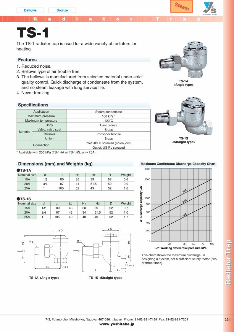
TS-1
Features1. Reduced noise.2. Bellows type of air trouble free.3. The bellows is manufactured from selected material under strict
quality control. Quick discharge of condensate from the system,and no steam leakage with long service life.
4. Never freezing.
SpecificationsSteam condensate
100 kPa *120˚C
Cast bronzeBrass
Phosphor bronzeBrass
Inlet: JIS R screwed (union joint)Outlet: JIS Rc screwed
ApplicationMaximum pressure
Maximum temperatureBody
Valve, valve seatBellowsUnion
Connection
Material
* Available with 200 kPa (TS-1HA or TS-1HS, only 25A).
Dimensions (mm) and Weights (kg) Maximum Continuous Discharge Capacity Chart
Nominal size15A20A25A
Weight0.60.91.6
d1/23/41
L1 H1
354152
H2 D525252
8087
105
3951.549
●TS-1A
Nominal size15A20A25A
Weight0.71.01.7
d1/23/41
L1 H1
283440
H2 D525252
8087
105
L2
434860
3951.549
●TS-1S
TS-1A<Angle type>
TS-1S<Straight type>
The TS-1 radiator trap is used for a wide variety of radiators forheating.
H1
H2
L1
R d
φ D
Rc d
TS-1A <Angle type>
H2
H1
φ D
R d
L1 L2
Rc d
TS-1S <Straight type>
3000
2000
1000
800
600
300
400
1020
∆P: Working differential pressure kPa35 50 70 100
25A
20A
15A
W:
Dis
char
ge
cap
acit
y L
/h
・ This chart shows the maximum discharge. Indesigning a system, set a sufficient safety factor (twoor three times).
P234-235_スチ 2011.3.10 10:29 PM ページ 1
R a d i a t o r T r a p
Rad
iato
r T
rap
Rad
iato
r T
rap
7-3, Futano-cho, Mizuho-ku, Nagoya, 467-0861, Japan Phone: 81-52-881-7199 Fax: 81-52-881-7201
www.yoshitake.jp235
トラ-00
SteamSteam
Bellows Bronze
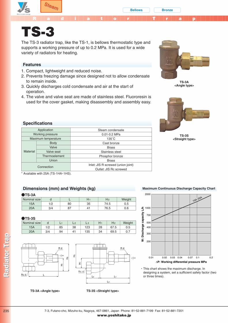
TS-3
SpecificationsSteam condensate
0.01-0.2 MPa135˚C
Cast bronzeBrass
Stainless steelPhosphor bronze
BrassInlet: JIS R screwed (union joint)
Outlet: JIS Rc screwed
ApplicationWorking pressure
Maximum temperatureBodyValve
Valve seatThermoelement
Union
Connection
Material
* Available with 25A (TS-1HA・1HS).
Dimensions (mm) and Weights (kg)
Nominal size15A20A
Weight0.50.6
d1/23/4
L H1
3541
H2
8087
74.576.5
●TS-3A
Nominal size15A20A
Weight0.50.7
d1/23/4
L1
8594
L3
123135
H1
2834
H2
67.569.5
L2
3841
●TS-3S
Features1. Compact, lightweight and reduced noise.2. Prevents freezing damage since designed not to allow condensate
to remain inside.3. Quickly discharges cold condensate and air at the start of
operation.4. The valve and valve seat are made of stainless steel. Fluororesin is
used for the cover gasket, making disassembly and assembly easy.
The TS-3 radiator trap, like the TS-1, is bellows thermostatic type andsupports a working pressure of up to 0.2 MPa. It is used for a widevariety of radiators for heating.
Rc d
H2
H1
L
R d
TS-3A <Angle type>
H2
H1
L3
L2 L1
R d
Rc d
TS-3S <Straight type>
Maximum Continuous Discharge Capacity Chart
TS-3S<Straight type>
2000
1000
700
500
400
300
200
0.01 0.02 0.03 0.04 0.07 0.1 0.2
15A・20A
∆P: Working differential pressure MPa
W:
Dis
char
ge
cap
acit
y L
/h
・ This chart shows the maximum discharge. Indesigning a system, set a sufficient safety factor (twoor three times).
TS-3A<Angle type>
P234-235_スチ 2011.3.10 10:29 PM ページ 2
R a d i a t o r T r a p
Rad
iato
r T
rap
Rad
iato
r T
rap
7-3, Futano-cho, Mizuho-ku, Nagoya, 467-0861, Japan Phone: 81-52-881-7199 Fax: 81-52-881-7201
www.yoshitake.jp236
トラ-08
Wax type Bronze
SteamSteam
Rc d
H2
H1
L
R d
H2
H1
L3
L2 L1
R d
Rc d
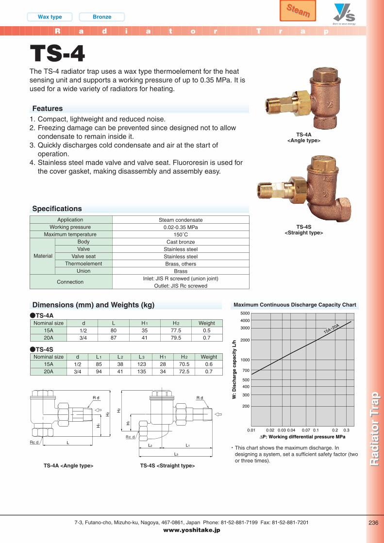
TS-4
Features1. Compact, lightweight and reduced noise.2. Freezing damage can be prevented since designed not to allow
condensate to remain inside it.3. Quickly discharges cold condensate and air at the start of
operation.4. Stainless steel made valve and valve seat. Fluororesin is used for
the cover gasket, making disassembly and assembly easy.
SpecificationsSteam condensate
0.02-0.35 MPa150˚C
Cast bronzeStainless steelStainless steelBrass, others
BrassInlet: JIS R screwed (union joint)
Outlet: JIS Rc screwed
ApplicationWorking pressure
Maximum temperatureBodyValve
Valve seatThermoelement
Union
Connection
Material
Dimensions (mm) and Weights (kg) Maximum Continuous Discharge Capacity Chart
Nominal size15A20A
Weight0.50.7
d1/23/4
L H1
3541
H2
8087
77.579.5
●TS-4A
Nominal size15A20A
Weight0.60.7
d1/23/4
H1
2834
L1
8594
L2
3841
L3
123135
H2
70.572.5
●TS-4S
TS-4A<Angle type>
TS-4S<Straight type>
The TS-4 radiator trap uses a wax type thermoelement for the heatsensing unit and supports a working pressure of up to 0.35 MPa. It isused for a wide variety of radiators for heating.
TS-4A <Angle type> TS-4S <Straight type>
5000
4000
3000
2000
1000
700
500
400
300
200
0.020.01 0.03 0.04 0.07 0.1 0.2 0.3
15A・20A
∆P: Working differential pressure MPa
W:
Dis
char
ge
cap
acit
y L
/h
・ This chart shows the maximum discharge. Indesigning a system, set a sufficient safety factor (twoor three times).
P236-237_スチ 2011.3.10 10:30 PM ページ 1
R a d i a t o r T r a p
Rad
iato
r T
rap
Rad
iato
r T
rap
7-3, Futano-cho, Mizuho-ku, Nagoya, 467-0861, Japan Phone: 81-52-881-7199 Fax: 81-52-881-7201
www.yoshitake.jp237
トラ-00
SteamSteam
WaterWater Bellows Bronze
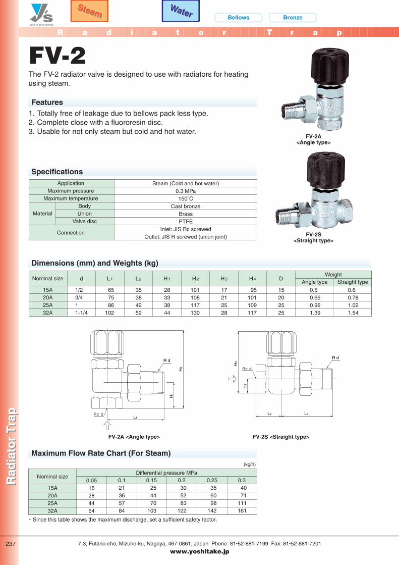
FV-2
Features1. Totally free of leakage due to bellows pack less type.2. Complete close with a fluororesin disc.3. Usable for not only steam but cold and hot water.
SpecificationsSteam (Cold and hot water)
0.3 MPa150˚C
Cast bronzeBrassPTFE
Inlet: JIS Rc screwedOutlet: JIS R screwed (union joint)
ApplicationMaximum pressure
Maximum temperatureBodyUnion
Valve disc
Connection
Material
FV-2A<Angle type>
FV-2S<Straight type>
The FV-2 radiator valve is designed to use with radiators for heatingusing steam.
Dimensions (mm) and Weights (kg)
Nominal size
15A20A25A32A
Weight
0.60.781.021.54
0.50.660.961.39
657586
102
35384252
28333844
101108117130
17212528
95101109117
15202525
Angle type Straight typed L1 L2 H1 H2 H3 H4 D
1/23/411-1/4
H2
H1
L1
R d
Rc d
FV-2A <Angle type>
H4
H3
L1L2
R d
Rc d
FV-2S <Straight type>
Maximum Flow Rate Chart (For Steam)
15A20A25A32A
Nominal size0.0516284464
0.121365784
0.20.15Differential pressure MPa
0.25 0.3254470
103
305283
122
356098
142
4071
111161
(kg/h)
・ Since this table shows the maximum discharge, set a sufficient safety factor.
P236-237_スチ 2011.3.15 11:09 AM ページ 2
S t e a m T r a p
Ste
am T
rap
Ste
am T
rap
7-3, Futano-cho, Mizuho-ku, Nagoya, 467-0861, Japan Phone: 81-52-881-7199 Fax: 81-52-881-7201
www.yoshitake.jp238
トラ-00
FeaturesModel
Picture
Application
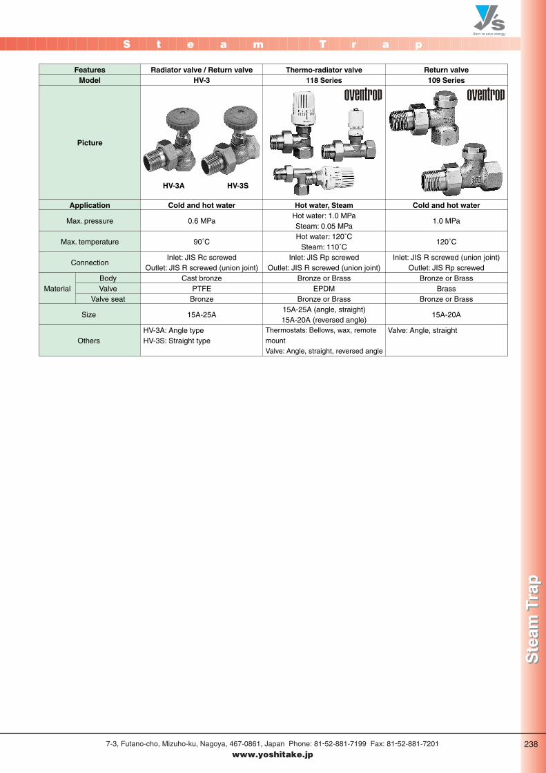
Radiator valve / Return valveHV-3
Cold and hot water
Thermo-radiator valve118 Series
Hot water, Steam
Material
Hot water: 1.0 MPaSteam: 0.05 MPaHot water: 120˚C
Steam: 110˚CInlet: JIS Rp screwed
Outlet: JIS R screwed (union joint)Bronze or Brass
EPDMBronze or Brass
15A-25A (angle, straight)15A-20A (reversed angle)
Return valve109 Series
Cold and hot water
1.0 MPa
120˚C
Inlet: JIS R screwed (union joint)Outlet: JIS Rp screwed
Bronze or BrassBrass
Bronze or Brass
15A-20A
0.6 MPa
90˚C
Inlet: JIS Rc screwedOutlet: JIS R screwed (union joint)
Cast bronzePTFE
Bronze
15A-25A
Max. pressure
Max. temperature
Connection
BodyValve
Valve seat
Size
Others Valve: Angle, straightThermostats: Bellows, wax, remote
mount
Valve: Angle, straight, reversed angle
HV-3A: Angle typeHV-3S: Straight type
HV-3A HV-3S
P238_スチ 2011.3.10 10:31 PM ページ 1


![steam trap performance[1]](https://img.pdfslide.net/doc/110x75/551b18ab4a795911748b45cc/steam-trap-performance1.jpg)