Embed Size (px)
Citation preview
BRITISH STANDARD BS EN 13414-3:2003+A1:2008
Steel wire rope slings —
Safety —
Part 3: Grommets and cable-laid slings
ICS 53.020.30
�������������� ���������������������������������������������������
Lice
nsed
Cop
y: I
P, L
ough
boro
ugh
Uni
vers
ity, 2
8/06
/201
3 23
:43,
Unc
ontr
olle
d C
opy,
(c)
The
Brit
ish
Sta
ndar
ds In
stitu
tion
2013
This British Standard was published under the authority of the Standards Committee and comes into effect on 17 September 2003
BS EN 13414-3:2003+A1:2008
National foreword
This British Standard is the UK implementation of EN 13414-3:2003+A1:2008. It supersedes BS EN 13414-3:2003 which is withdrawn.
The start and finish of text introduced or altered by amendment is indicated in the text by tags. Tags indicating changes to CEN text carry the number of the CEN amendment. For example, text altered by CEN amendment A1 is indicated by .
The UK participation in its preparation was entrusted to Technical Committee MHE/2, Wire ropes.
A list of organizations represented on this committee can be obtained on request to its secretary.
This publication does not purport to include all the necessary provisions of a contract. Users are responsible for its correct application.
Compliance with a British Standard cannot confer immunity from legal
obligations.
ISBN
Amendments�corrigenda issued since publication
Date Comments
Implementation of CEN amendment A1:2008
© BSI 2009
30 April 2009
978 0 580 60264 1
Lice
nsed
Cop
y: I
P, L
ough
boro
ugh
Uni
vers
ity, 2
8/06
/201
3 23
:43,
Unc
ontr
olle
d C
opy,
(c)
The
Brit
ish
Sta
ndar
ds In
stitu
tion
2013
EUROPEAN STANDARD
NORME EUROPÉENNE
EUROPÄISCHE NORM
EN 13414-3:2003+A1
November 2008
ICS 53.020.30 Supersedes EN 13413-3:2003
English Version
Steel wire rope slings - Safety - Part 3: Grommets and cable-laid slings
Elingues en câbles d'acier - Sécurité - Partie 3: Estropes et élingues en grelin
Anschlagseile aus Strahldrahtseilen - Sicherheit - Teil 3: Grummets und Kabelschlag-Anschlagseile
This European Standard was approved by CEN on 25 March 2003 and includes Corrigendum 1 issued by CEN on 5 May 2004 and Amendment 1 approved by CEN on 18 September 2008. CEN members are bound to comply with the CEN/CENELEC Internal Regulations which stipulate the conditions for giving this European Standard the status of a national standard without any alteration. Up-to-date lists and bibliographical references concerning such national standards may be obtained on application to the CEN Management Centre or to any CEN member. This European Standard exists in three official versions (English, French, German). A version in any other language made by translation under the responsibility of a CEN member into its own language and notified to the CEN Management Centre has the same status as the official versions. CEN members are the national standards bodies of Austria, Belgium, Bulgaria, Cyprus, Czech Republic, Denmark, Estonia, Finland, France, Germany, Greece, Hungary, Iceland, Ireland, Italy, Latvia, Lithuania, Luxembourg, Malta, Netherlands, Norway, Poland, Portugal, Romania, Slovakia, Slovenia, Spain, Sweden, Switzerland and United Kingdom.
EUROPEAN COMMITTEE FOR STANDARDIZATION
C O M I T É E U R O P É E N D E N O R M A LI S A T I O N
EUR OP ÄIS C HES KOM ITEE FÜR NOR M UNG
Management Centre: rue de Stassart, 36 B-1050 Brussels
© 2008 CEN All rights of exploitation in any form and by any means reserved worldwide for CEN national Members.
Ref. No. EN 13414-3:2003+A1:2008: E
Lice
nsed
Cop
y: I
P, L
ough
boro
ugh
Uni
vers
ity, 2
8/06
/201
3 23
:43,
Unc
ontr
olle
d C
opy,
(c)
The
Brit
ish
Sta
ndar
ds In
stitu
tion
2013
EN 13414-3:2003+A1:2008 (E)
2
Contents
Page
Foreword......................................................................................................................................................................3
Introduction .................................................................................................................................................................4
1 Scope ..............................................................................................................................................................4
2 Normative references ....................................................................................................................................4
3 Terms and Definitions ...................................................................................................................................5
4 Hazards ...........................................................................................................................................................6
5 Safety requirements and/or measures ........................................................................................................6
6 Verification of the safety requirements and/or measures .......................................................................10
7 Information for use ......................................................................................................................................10
Annex A (normative) Combination of lay factors for grommets and cable-laid slings ....................................11
Annex B (normative) Determination of the length of a grommet........................................................................12
Annex C (normative) Pin sizes for measurements of lengths ............................................................................14
Annex D (normative) Hand splices ........................................................................................................................15
Annex E (normative) Certificate for grommets.....................................................................................................16
Annex F (normative) Certificate for cable-laid slings ..........................................................................................17
Annex G (informative) Tables of working load limits...........................................................................................18
Annex ZA (informative) !!!!Relationship between this European Standard and the Essential Requirements of EU Directive 98/37/EC""""...............................................................................................26
Annex ZB (informative) !!!!Relationship between this European Standard and the Essential Requirements of EU Directive 2006/42/EC""""...........................................................................................27
BS EN 13414-3:2003+A1:2008
Lice
nsed
Cop
y: I
P, L
ough
boro
ugh
Uni
vers
ity, 2
8/06
/201
3 23
:43,
Unc
ontr
olle
d C
opy,
(c)
The
Brit
ish
Sta
ndar
ds In
stitu
tion
2013

EN 13414-3:2003+A1:2008 (E)
3
Foreword
This document (EN 13414-3:2003+A1:2008) has been prepared by Technical Committee CEN/TC 168 “Chains, ropes, webbings, slings and accessories - Safety”, the secretariat of which is held by BSI.
This European Standard shall be given the status of a national standard, either by publication of an identical text or by endorsement, at the latest by May 2009, and conflicting national standards shall be withdrawn at the latest by December 2009.
This document supersedes EN 13414-3:2003.
This document includes Amendment 1, approved by CEN on 2008-09-18 and Corrigendum 1 issued by CEN on 2004-05-05.
The start and finish of text introduced or altered by amendment is indicated in the text by tags !".
The modifications of the related CEN Corrigendum have been implemented at the appropriate places in the text and are indicated by the tags ˜ ™.
This document has been prepared under a mandate given to CEN by the European Commission and the European Free Trade Association, and supports essential requirements of EU Directive(s).
!For relationship with EU Directive(s), see informative Annexes ZA and ZB, which are integral parts of this document."
The other parts of this European Standard are:
Part 1 Slings for general lifting service
Part 2 Specification for information for use and maintenance ˜to™ be provided by the manufacturer
Annexes A to F are normative. Annex G is informative.
According to the CEN/CENELEC Internal Regulations, the national standards organizations of the following countries are bound to implement this European Standard: Austria, Belgium, Bulgaria, Cyprus, Czech Republic, Denmark, Estonia, Finland, France, Germany, Greece, Hungary, Iceland, Ireland, Italy, Latvia, Lithuania, Luxembourg, Malta, Netherlands, Norway, Poland, Portugal, Romania, Slovakia, Slovenia, Spain, Sweden, Switzerland and United Kingdom.
BS EN 13414-3:2003+A1:2008
Lice
nsed
Cop
y: I
P, L
ough
boro
ugh
Uni
vers
ity, 2
8/06
/201
3 23
:43,
Unc
ontr
olle
d C
opy,
(c)
The
Brit
ish
Sta
ndar
ds In
stitu
tion
2013
EN 13414-3:2003+A1:2008 (E)
4
Introduction
This Part of the standard has been prepared to provide a means of complying with the essential safety requirements of the Machinery Directive and associated EFTA regulations. Purchasers are advised to specify in their purchasing contract that the supplier operates a quality management system applicable to this standard (e.g. ISO EN 9001) to ensure that products claimed to comply consistently achieve the required level of quality. The coefficient of utilization (Zp) used in this standard for slings with a diameter greater than 60 mm is lower than
that normally used for general service wire rope slings. This is justified for the following reasons.
a) Slings over 60 mm diameter are not intended for general service and are subjected to special conditions relating to design, construction, frequency of use, service and discard.
b) The mass of the load is generally calculated or measured with considerable accuracy and as such slings are usually specially manufactured for one or a limited number of special lifts.
c) The lifting operation is controlled and supervised.
d) The dynamic factors, e.g. shock loading, are limited.
These factors reduce the unknown aspects which dictate that slings in general service require a higher coefficient of utilization; lower coefficients have been and are used with confidence.
1 Scope
This European Standard specifies the construction requirements, calculation of WLL, testing and certification of steel wire rope grommets, cable-laid grommets and cable-laid slings using strand and wire rope conforming to EN 12385-4.
The hazards covered by this standard are identified in clause 4.
This standard covers ferrule-secured cable-laid slings up to 60mm.
2 Normative references
This European Standard incorporates by dated or undated reference, provisions from other publications. These normative references are cited at the appropriate places in the text and the publications are listed hereafter. For dated references, subsequent amendments to or revisions of any of these publications apply to this European Standard only when incorporated in it by amendment or revision. For undated references the latest edition of the publication referred to, applies. EN 292-2:1991/A1:1995, Safety of machinery – Basic concepts, general principles for design Part 2: Technical principles and specifications (Amendment 1: 1995)
EN 1050:1996, Safety of machinery – Principles for risk assessment
˜EN 12385-4:2002™, Steel wire ropes – Safety – Part 4: Stranded ropes for general lifting applications
prEN 13411-3, Terminations for steel wire ropes – Safety – Part 3: Ferrules and ferrule securing
BS EN 13414-3:2003+A1:2008
Lice
nsed
Cop
y: I
P, L
ough
boro
ugh
Uni
vers
ity, 2
8/06
/201
3 23
:43,
Unc
ontr
olle
d C
opy,
(c)
The
Brit
ish
Sta
ndar
ds In
stitu
tion
2013
EN 13414-3:2003+A1:2008 (E)
5
3 Terms and Definitions
For the purposes of this standard the following terms and definitions apply. 3.1 wire rope grommet
endless wire rope sling made from one continuous length of strand, formed to make a body composed of six strands around a strand core
NOTE The strand ends are tucked into the body forming the core, with the tuck position diametrically opposite to the core butt position.
3.2 cable-laid grommet
endless wire rope sling made from one or two continuous lengths of rope, formed to make a body composed of six ropes around a rope core
NOTE The rope ends are tucked into the body forming the core, with the tuck position(s) diametrically opposite to the core butt position(s).
3.3 cable-laid sling
sling formed from a wire rope constructed of six unit ropes laid as outers over one core unit rope, with a termination at each end, usually in the form of a spliced eye
3.4 working load limit (WLL)
maximum mass which a sling is authorized to sustain in general service
3.5 competent person
designated person, suitably trained, qualified by knowledge and practical experience, and in possession of the necessary instructions to enable the required calculation of WLL and examination to be carried out
3.6 nominal diameter of grommet or cable laid sling dimension by which the sling is designated
BS EN 13414-3:2003+A1:2008
Lice
nsed
Cop
y: I
P, L
ough
boro
ugh
Uni
vers
ity, 2
8/06
/201
3 23
:43,
Unc
ontr
olle
d C
opy,
(c)
The
Brit
ish
Sta
ndar
ds In
stitu
tion
2013
EN 13414-3:2003+A1:2008 (E)
6
4 Hazards
Accidental release of a load, or release of a load due to failure of a sling or a component puts at risk, either directly or indirectly, the safety or health of those persons within the danger zone.
These aspects of safe use associated with good practice are given in prEN 13414-2.
Table 1 contains all the hazards which require action to reduce risk identified by risk assessment as being specific and significant for slings and their components.
Table 1 — Hazards and associated requirements
Hazards identified in annex A of EN 1050 : 1996
Relevant clause of annex A of EN 292-2: 1991/A1: 1995
Relevant clause/sub-clause of this Part of EN 13414
1.1.5 Mechanical hazard due 4.1.2.3 5 and 6 to inadequacy of 4.1.2.5 5 and 6 strength 4.1.2.4 7 4.3.2 7 10.4 Errors of fitting hazard 1.5.4 5
5 Safety requirements and/or measures
5.1 Grommets
5.1.1 Production of grommets
During the production of grommets a temporary rigid core shall be used. Grommets and cable-laid ropes shall be produced using a method which ensures that the rope or strand tensions are equalized and that the finished product is free from visible waviness.
5.1.2 Construction of wire rope grommet
The strand used to form the wire rope grommet shall be one of those used to form ropes specified in table 2, 4, 6, 8, 11, 12 and 13 of ˜EN 12385-4:2002™.
The length of the circumference shall be at least five times the grommet lay length. The core butt position shall be clearly marked by red paint applied over any serving.
5.1.3 Construction of cable-laid grommet
Cable-laid grommets shall be constructed in accordance with A.1. The unit ropes shall be of 6- or 8-strand construction selected from those specified in tables 2, 3, 4, 5, 6, 7, 8, 11, 12 and 13 of ˜EN 12385-4:2002™. Ropes over 60 mm diameter shall have steel rope cores.
The length of the circumference shall be at least five times the grommet lay length.
The core butt position shall be clearly marked by red paint applied over any servings.
NOTE The grommet should never be bent at this marked position.
BS EN 13414-3:2003+A1:2008
Lice
nsed
Cop
y: I
P, L
ough
boro
ugh
Uni
vers
ity, 2
8/06
/201
3 23
:43,
Unc
ontr
olle
d C
opy,
(c)
The
Brit
ish
Sta
ndar
ds In
stitu
tion
2013
EN 13414-3:2003+A1:2008 (E)
7
5.1.4 Length of grommet
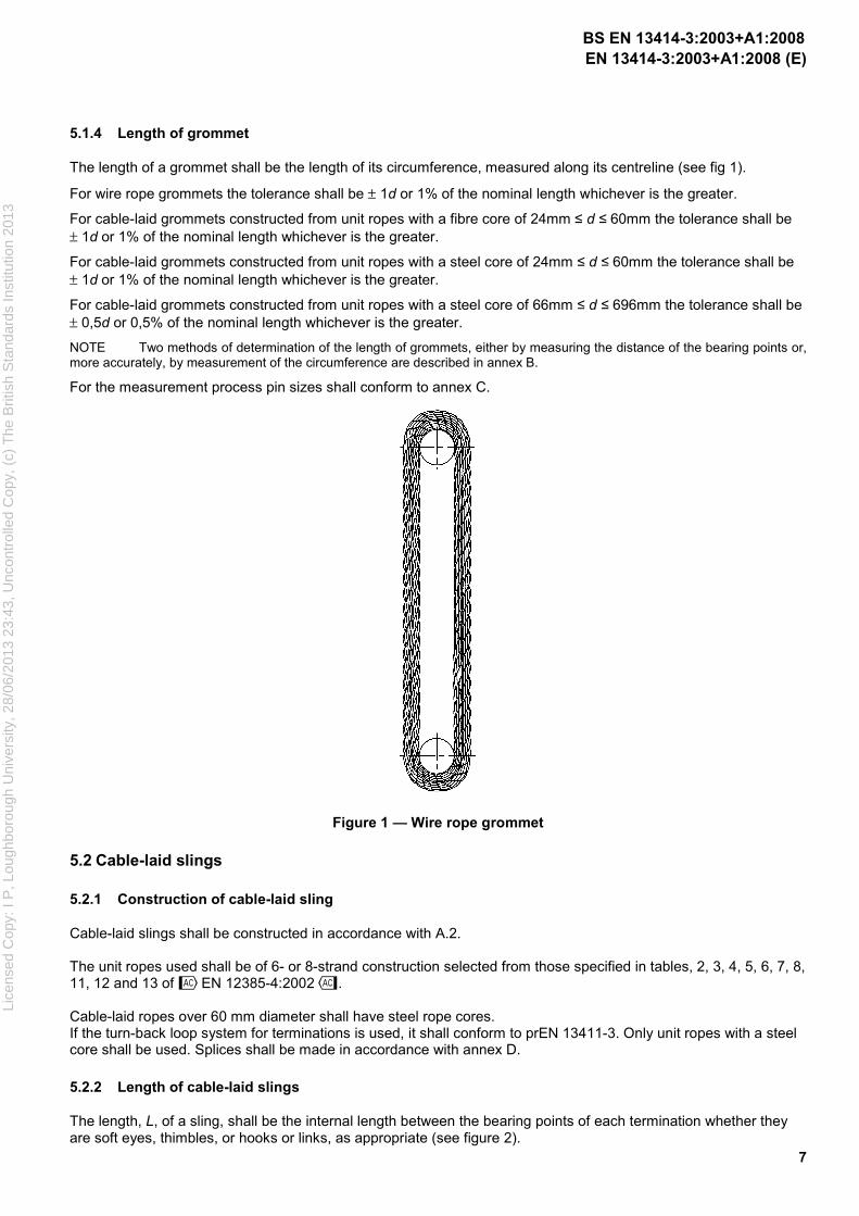
The length of a grommet shall be the length of its circumference, measured along its centreline (see fig 1).
For wire rope grommets the tolerance shall be ± 1d or 1% of the nominal length whichever is the greater.
For cable-laid grommets constructed from unit ropes with a fibre core of 24mm � d � 60mm the tolerance shall be ± 1d or 1% of the nominal length whichever is the greater.
For cable-laid grommets constructed from unit ropes with a steel core of 24mm � d � 60mm the tolerance shall be ± 1d or 1% of the nominal length whichever is the greater.
For cable-laid grommets constructed from unit ropes with a steel core of 66mm � d � 696mm the tolerance shall be ± 0,5d or 0,5% of the nominal length whichever is the greater.
NOTE Two methods of determination of the length of grommets, either by measuring the distance of the bearing points or, more accurately, by measurement of the circumference are described in annex B.
For the measurement process pin sizes shall conform to annex C.
Figure 1 — Wire rope grommet
5.2 Cable-laid slings
5.2.1 Construction of cable-laid sling
Cable-laid slings shall be constructed in accordance with A.2. The unit ropes used shall be of 6- or 8-strand construction selected from those specified in tables, 2, 3, 4, 5, 6, 7, 8, 11, 12 and 13 of ˜EN 12385-4:2002™. Cable-laid ropes over 60 mm diameter shall have steel rope cores. If the turn-back loop system for terminations is used, it shall conform to prEN 13411-3. Only unit ropes with a steel core shall be used. Splices shall be made in accordance with annex D.
5.2.2 Length of cable-laid slings
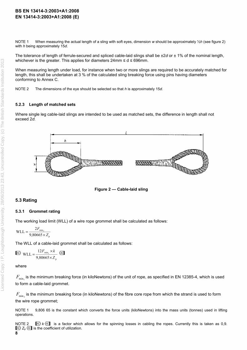
The length, L, of a sling, shall be the internal length between the bearing points of each termination whether they are soft eyes, thimbles, or hooks or links, as appropriate (see figure 2).
BS EN 13414-3:2003+A1:2008
Lice
nsed
Cop
y: I
P, L
ough
boro
ugh
Uni
vers
ity, 2
8/06
/201
3 23
:43,
Unc
ontr
olle
d C
opy,
(c)
The
Brit
ish
Sta
ndar
ds In
stitu
tion
2013
EN 13414-3:2003+A1:2008 (E)
8
NOTE 1 When measuring the actual length of a sling with soft eyes, dimension w should be approximately ½h (see figure 2) with h being approximately 15d.
The tolerance of length of ferrule-secured and spliced cable-laid slings shall be ±2d or ± 1% of the nominal length, whichever is the greater. This applies for diameters 24mm � d � 696mm. When measuring length under load, for instance when two or more slings are required to be accurately matched for length, this shall be undertaken at 3 % of the calculated sling breaking force using pins having diameters conforming to Annex C. NOTE 2 The dimensions of the eye should be selected so that h is approximately 15d.
5.2.3 Length of matched sets
Where single leg cable-laid slings are intended to be used as matched sets, the difference in length shall not exceed 2d.
Figure 2 — Cable-laid sling
5.3 Rating
5.3.1 Grommet rating
The working load limit (WLL) of a wire rope grommet shall be calculated as follows:
p
min
9,80665
2WLL 2
Z
F
×=
The WLL of a cable-laid grommet shall be calculated as follows:
˜
p
min
9,80665
12WLL 1
Z
kF
×
×= ™
where
1minF is the minimum breaking force (in kiloNewtons) of the unit of rope, as specified in EN 12385-4, which is used
to form a cable-laid grommet.
2minF is the minimum breaking force (in kiloNewtons) of the fibre core rope from which the strand is used to form
the wire rope grommet;
NOTE 1 9,806 65 is the constant which converts the force units (kiloNewtons) into the mass units (tonnes) used in lifting operations.
NOTE 2 ˜k™ is a factor which allows for the spinning losses in cabling the ropes. Currently this is taken as 0,9. ˜Zp™ is the coefficient of utilization.
BS EN 13414-3:2003+A1:2008
Lice
nsed
Cop
y: I
P, L
ough
boro
ugh
Uni
vers
ity, 2
8/06
/201
3 23
:43,
Unc
ontr
olle
d C
opy,
(c)
The
Brit
ish
Sta
ndar
ds In
stitu
tion
2013
EN 13414-3:2003+A1:2008 (E)
9
For grommet rope diameters less than 60 mm, ˜Zp™ shall be not less than 5.
For grommet rope diameters (d) of 60 mm up to 150 mm, Zp shall be calculated in accordance with the following equation:
Zp = 6,33 - 0,022 d
For grommet rope diameters greater than 150 mm, ˜Zp™ shall be not less than 3.
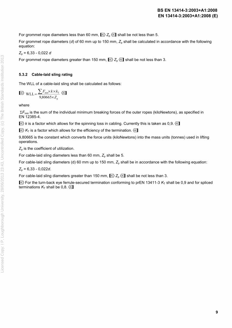
5.3.2 Cable-laid sling rating
The WLL of a cable-laid sling shall be calculated as follows:
˜
p
Tmin
80665,9WLL
Z
kkF
×
××=� ™
where
ΣFmin is the sum of the individual minimum breaking forces of the outer ropes (kiloNewtons), as specified in EN 12385-4.
˜k is a factor which allows for the spinning loss in cabling. Currently this is taken as 0,9.™
˜KT is a factor which allows for the efficiency of the termination.™
9,80665 is the constant which converts the force units (kiloNewtons) into the mass units (tonnes) used in lifting operations.
Zp is the coefficient of utilization.
For cable-laid sling diameters less than 60 mm, Zp shall be 5.
For cable-laid sling diameters (d) 60 mm up to 150 mm, Zp shall be in accordance with the following equation:
Zp = 6,33 - 0,022d.
For cable-laid sling diameters greater than 150 mm, ˜Zp™ shall be not less than 3.
˜For the turn-back eye ferrule-secured termination conforming to prEN 13411-3 KT shall be 0,9 and for spliced terminations KT shall be 0,8.™
BS EN 13414-3:2003+A1:2008
Lice
nsed
Cop
y: I
P, L
ough
boro
ugh
Uni
vers
ity, 2
8/06
/201
3 23
:43,
Unc
ontr
olle
d C
opy,
(c)
The
Brit
ish
Sta
ndar
ds In
stitu
tion
2013
EN 13414-3:2003+A1:2008 (E)
10
6 Verification of the safety requirements and/or measures
6.1 Construction of grommet and cable-laid sling
The requirements of 5.1.2, 5.1.3, 5.2.1 and annexes A and D shall be confirmed by visual inspection, measurement and by examination of the rope supplier's records.
6.2 Length of grommet and cable-laid sling
The lengths defined in 5.1.4, 5.2.2 and 5.2.3 shall be measured with a steel tape graduated in increments of 1 mm.
The grommet length shall be verified in accordance with annex B.
6.3 Rating
The calculation of 5.3 shall be verified by a re-check and by examination of the rope supplier's records.
7 Information for use
7.1 Marking
Each sling or grommet shall be legibly and durably marked with at least the following information
a) the manufacturer's identifying mark;
b) numbers and/or letters identifying the sling or grommet with the certificate conforming to 7.2;
c) the working load limit;
d) any statutory marking.
NOTE Within the European Union this means CE marking
Each completed sling or grommet shall be permanently marked so that it can be identified with its Certificate (see annex E).
7.2 Certification
A certificate in accordance with annex E for a grommet sling or annex F for a cable-laid sling shall be completed for each sling or batch of slings.
BS EN 13414-3:2003+A1:2008
Lice
nsed
Cop
y: I
P, L
ough
boro
ugh
Uni
vers
ity, 2
8/06
/201
3 23
:43,
Unc
ontr
olle
d C
opy,
(c)
The
Brit
ish
Sta
ndar
ds In
stitu
tion
2013
EN 13414-3:2003+A1:2008 (E)
11
Annex A (normative)
Combination of lay factors for grommets and cable-laid slings
A.1 Grommets
A.1.1 General
Grommets shall be manufactured in accordance with the following combinations of unit rope and grommet lay factors.
A.1.2 Lay factors
The unit rope lay factor shall be at least 6 times the nominal rope diameter and at most 7,5 times the nominal rope diameter. The grommet shall be at least 6 times the nominal grommet diameter and at most 7,5 times the nominal grommet diameter.
A.2 Cable-laid slings
A.2.1 General
The cable-laid rope shall be manufactured in accordance with the following combinations of unit rope and cable-laid rope lay directions and lay factors.
A.2.2 Lay directions and type
The core unit rope shall be right- or left-hand ordinary lay or right- or left-hand Lang lay. The diameter of the core rope shall be at least 10 %, but not greater than 15 %, larger than the diameter of the main rope. The outer unit ropes shall be left-hand ordinary lay or Lang lay, in which case the cable-laid rope shall be right-hand lay; or the outer unit ropes shall be right-hand ordinary lay or Lang lay, in which case the cable-laid rope shall be left-hand lay. Core unit rope and the outer unit ropes shall have the same direction of lay.
A.2.3 Lay factors
The core unit and outer unit ropes shall have a lay factor which is a minimum of six times the nominal rope diameter and a maximum of 7.5 times the nominal rope diameter. Cable-laid rope shall have a lay factor which is a minimum of 6 times the nominal cable-laid rope diameter and a maximum of 7,5 times the nominal cable-laid rope diameter.
BS EN 13414-3:2003+A1:2008
Lice
nsed
Cop
y: I
P, L
ough
boro
ugh
Uni
vers
ity, 2
8/06
/201
3 23
:43,
Unc
ontr
olle
d C
opy,
(c)
The
Brit
ish
Sta
ndar
ds In
stitu
tion
2013
EN 13414-3:2003+A1:2008 (E)
12
Annex B (normative)
Determination of the length of a grommet
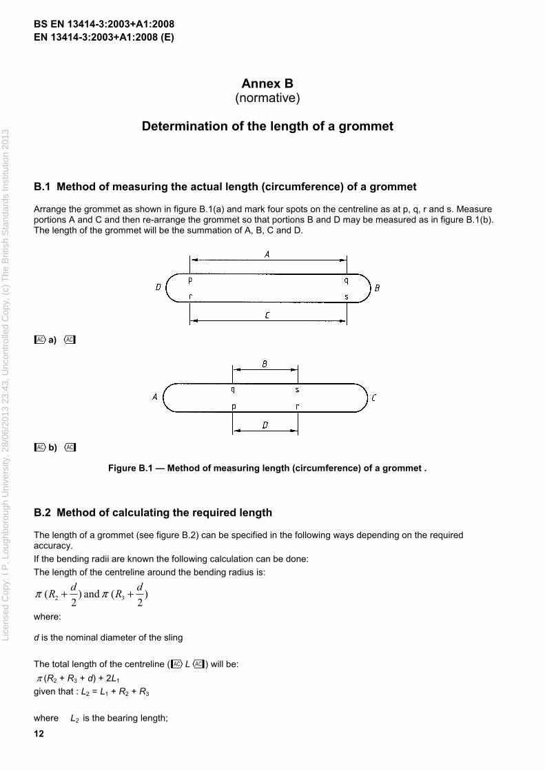
B.1 Method of measuring the actual length (circumference) of a grommet
Arrange the grommet as shown in figure B.1(a) and mark four spots on the centreline as at p, q, r and s. Measure portions A and C and then re-arrange the grommet so that portions B and D may be measured as in figure B.1(b). The length of the grommet will be the summation of A, B, C and D.
˜a) ™
˜b) ™
Figure B.1 — Method of measuring length (circumference) of a grommet .
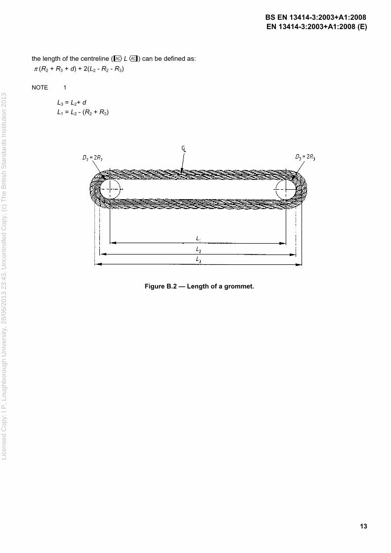
B.2 Method of calculating the required length
The length of a grommet (see figure B.2) can be specified in the following ways depending on the required accuracy.
If the bending radii are known the following calculation can be done:
The length of the centreline around the bending radius is:
)2
( and )2
( 32
dR
dR ++ ππ
where: d is the nominal diameter of the sling
The total length of the centreline (˜L™) will be:
π (R2 + R3 + d) + 2L1
given that : L2 = L1 + R2 + R3
where L2 is the bearing length;
BS EN 13414-3:2003+A1:2008
Lice
nsed
Cop
y: I
P, L
ough
boro
ugh
Uni
vers
ity, 2
8/06
/201
3 23
:43,
Unc
ontr
olle
d C
opy,
(c)
The
Brit
ish
Sta
ndar
ds In
stitu
tion
2013
EN 13414-3:2003+A1:2008 (E)
13
the length of the centreline (˜L™) can be defined as:
π (R2 + R3 + d) + 2(L2 - R2 - R3)
NOTE 1
L3 = L2+ d
L1 = L2 - (R2 + R3)
Figure B.2 — Length of a grommet.
BS EN 13414-3:2003+A1:2008
Lice
nsed
Cop
y: I
P, L
ough
boro
ugh
Uni
vers
ity, 2
8/06
/201
3 23
:43,
Unc
ontr
olle
d C
opy,
(c)
The
Brit
ish
Sta
ndar
ds In
stitu
tion
2013
EN 13414-3:2003+A1:2008 (E)
14
Annex C (normative)
Pin sizes for measurements of lengths
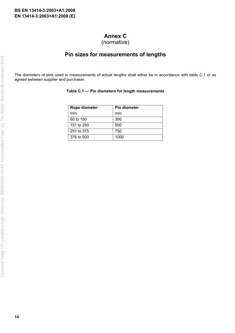
The diameters of pins used in measurements of actual lengths shall either be in accordance with table C.1 or as agreed between supplier and purchaser.
Table C.1 — Pin diameters for length measurements
Rope diameter
mm
Pin diameter
mm
60 to 150 300
151 to 250 500
251 to 375 750
376 to 500 1000
BS EN 13414-3:2003+A1:2008
Lice
nsed
Cop
y: I
P, L
ough
boro
ugh
Uni
vers
ity, 2
8/06
/201
3 23
:43,
Unc
ontr
olle
d C
opy,
(c)
The
Brit
ish
Sta
ndar
ds In
stitu
tion
2013

EN 13414-3:2003+A1:2008 (E)
15
Annex D (normative)
Hand splices
Hand splices shall be made by either of the following methods.
a) A cross tuck splice which consists of at least five tucks (not including the start) consisting of at least three tucks with the complete outer unit ropes. These tucks shall be over one and under two against the lay of the rope, except that the first tuck only of any one unit rope may be with the lay.
b) At least six tucks (not including the start) consisting of five tucks with the complete outer unit rope with the lay of the rope, and one tuck with the complete outer unit rope against the lay of the rope. The sixth tuck shall be made with one half of the strands from the outer unit ropes or with half of the outer unit ropes. All tucks shall be over one and under two.
The core shall be split and shall be worked in with the splice and not cut out. A length of tail at least three times the diameter of the cable-laid rope shall be left after the last tuck and seized to the main body of the rope.
The minimum length between the last tucks of the splices shall, in all cases, be at least 15d, where d is the nominal diameter of the cable-laid rope forming the sling. If the sling body is to be doubled, then this minimum length shall be agreed by the interested parties but not be less than 20d.
BS EN 13414-3:2003+A1:2008
Lice
nsed
Cop
y: I
P, L
ough
boro
ugh
Uni
vers
ity, 2
8/06
/201
3 23
:43,
Unc
ontr
olle
d C
opy,
(c)
The
Brit
ish
Sta
ndar
ds In
stitu
tion
2013
EN 13414-3:2003+A1:2008 (E)
16
Annex E (normative)
Certificate for grommets
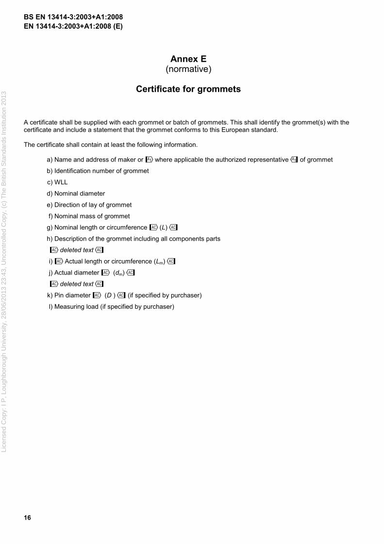
A certificate shall be supplied with each grommet or batch of grommets. This shall identify the grommet(s) with the certificate and include a statement that the grommet conforms to this European standard. The certificate shall contain at least the following information.
a) Name and address of maker or !where applicable the authorized representative" of grommet
b) Identification number of grommet
c) WLL
d) Nominal diameter
e) Direction of lay of grommet
f) Nominal mass of grommet
g) Nominal length or circumference ˜(L)™
h) Description of the grommet including all components parts
˜deleted text™
i) ̃ Actual length or circumference (Lm)™
j) Actual diameter ˜ (dm)™
˜deleted text™
k) Pin diameter ˜ (D )™ (if specified by purchaser)
l) Measuring load (if specified by purchaser)
BS EN 13414-3:2003+A1:2008
Lice
nsed
Cop
y: I
P, L
ough
boro
ugh
Uni
vers
ity, 2
8/06
/201
3 23
:43,
Unc
ontr
olle
d C
opy,
(c)
The
Brit
ish
Sta
ndar
ds In
stitu
tion
2013

EN 13414-3:2003+A1:2008 (E)
17
Annex F (normative)
Certificate for cable-laid slings
A certificate shall be supplied with each sling or batch of slings. This shall identify the sling(s) with the certificate and include a statement that the sling conforms to this European standard. The certificate shall contain at least the following information. a) Name and address of maker or !where applicable the authorized representative" of sling
b) Identification number of sling
c) WLL
d) Nominal diameter
e) Direction of lay of sling
f) Nominal mass of sling
g) Nominal length or circumference ˜(L)™
h) Description of the sling including all components parts
˜deleted text™
i) Actual length ˜(Lm)™. (State whether under load or no load)
j) Actual diameter ˜(dm)™
k) Eye length ˜(h1)™
l) Eye length ˜(h2)™
m) ˜Approximate splice length from beginning of eye to last tuck – splice 1™
n) ˜Approximate splice length from beginning of eye to last tuck – splice 2™
o) ˜Tail length – splice 1 Tail length – splice 2™
p) Length between last tucks ˜deleted text™
q) Pin diameter ˜(D)™ (if specified by purchaser)
r) Measuring load (if specified by purchaser)
BS EN 13414-3:2003+A1:2008
Lice
nsed
Cop
y: I
P, L
ough
boro
ugh
Uni
vers
ity, 2
8/06
/201
3 23
:43,
Unc
ontr
olle
d C
opy,
(c)
The
Brit
ish
Sta
ndar
ds In
stitu
tion
2013
EN 13414-3:2003+A1:2008 (E)
18
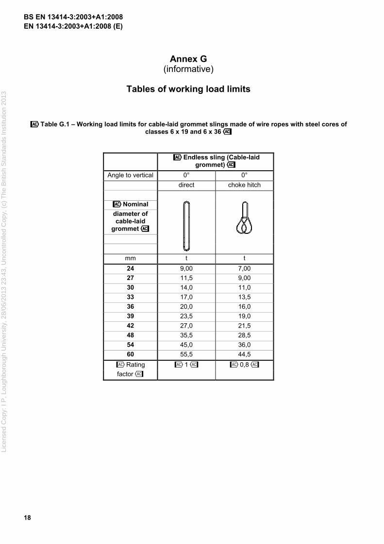
Annex G (informative)
Tables of working load limits
˜̃̃̃Table G.1 – Working load limits for cable-laid grommet slings made of wire ropes with steel cores of classes 6 x 19 and 6 x 36™™™™
˜̃̃̃Endless sling (Cable-laid grommet)™™™™
Angle to vertical 0° 0°
direct choke hitch
˜̃̃̃Nominal
diameter of cable-laid
grommet™™™™
mm t t
24 9,00 7,00
27 11,5 9,00
30 14,0 11,0
33 17,0 13,5
36 20,0 16,0
39 23,5 19,0
42 27,0 21,5
48 35,5 28,5
54 45,0 36,0
60 55,5 44,5
˜1™ ˜0,8™ ˜Rating
factor™
BS EN 13414-3:2003+A1:2008
Lice
nsed
Cop
y: I
P, L
ough
boro
ugh
Uni
vers
ity, 2
8/06
/201
3 23
:43,
Unc
ontr
olle
d C
opy,
(c)
The
Brit
ish
Sta
ndar
ds In
stitu
tion
2013
EN 13414-3:2003+A1:2008 (E)
19
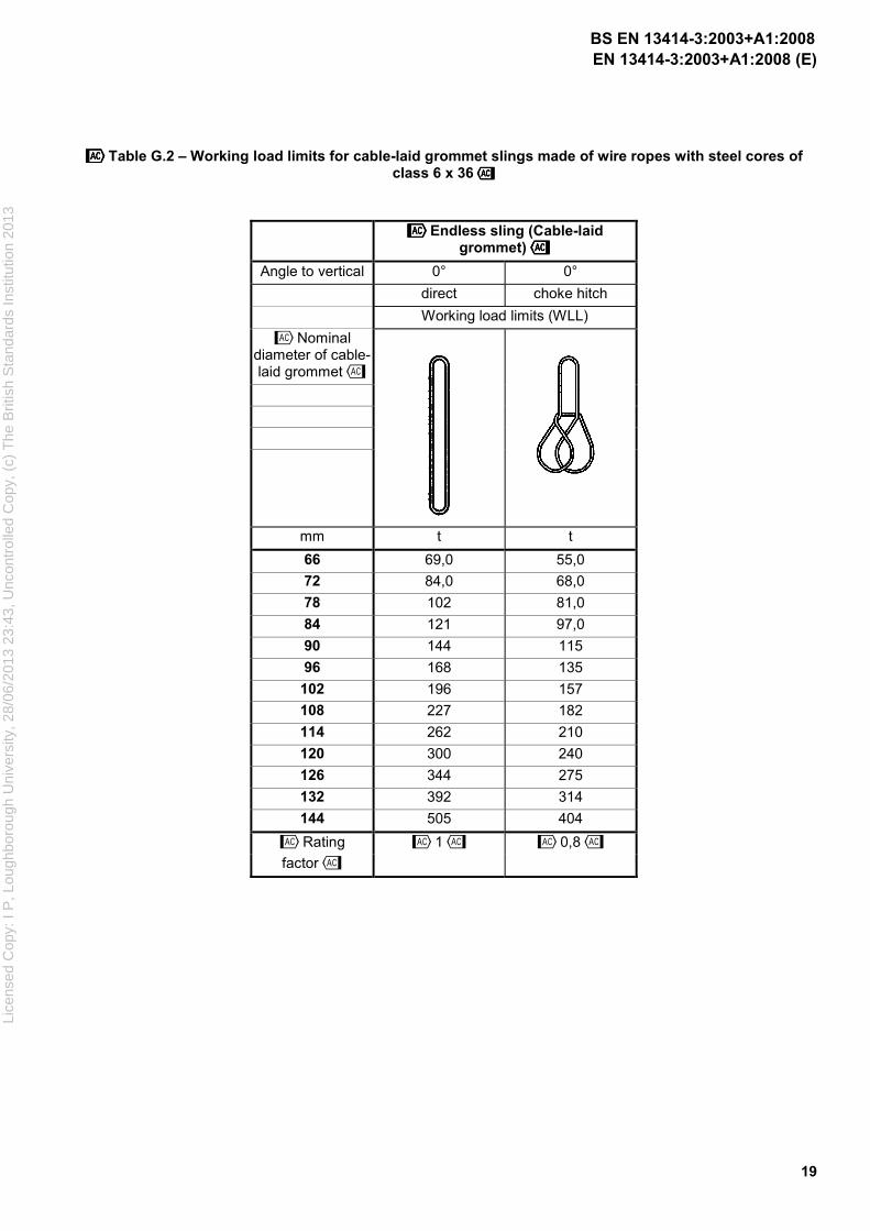
˜̃̃̃Table G.2 – Working load limits for cable-laid grommet slings made of wire ropes with steel cores of class 6 x 36™™™™
˜̃̃̃Endless sling (Cable-laid grommet)™™™™
Angle to vertical 0° 0°
direct choke hitch
Working load limits (WLL)
˜Nominal diameter of cable-laid grommet™
mm t t
66 69,0 55,0
72 84,0 68,0
78 102 81,0
84 121 97,0
90 144 115
96 168 135
102 196 157
108 227 182
114 262 210
120 300 240
126 344 275
132 392 314
144 505 404
˜Rating ˜1™ ˜0,8™
factor™
BS EN 13414-3:2003+A1:2008
Lice
nsed
Cop
y: I
P, L
ough
boro
ugh
Uni
vers
ity, 2
8/06
/201
3 23
:43,
Unc
ontr
olle
d C
opy,
(c)
The
Brit
ish
Sta
ndar
ds In
stitu
tion
2013
EN 13414-3:2003+A1:2008 (E)
20
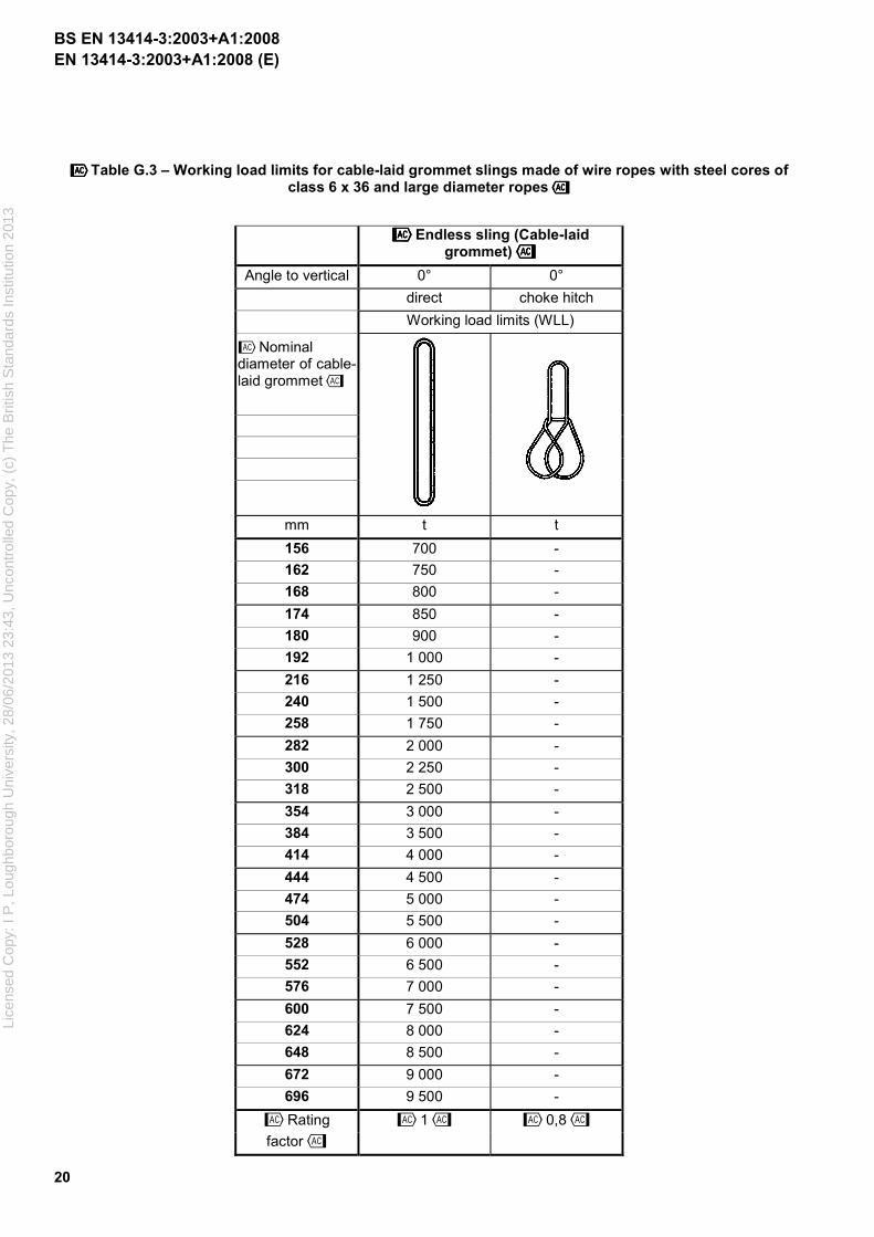
˜̃̃̃Table G.3 – Working load limits for cable-laid grommet slings made of wire ropes with steel cores of class 6 x 36 and large diameter ropes™™™™
˜̃̃̃Endless sling (Cable-laid grommet)™™™™
Angle to vertical 0° 0°
direct choke hitch
Working load limits (WLL)
˜Nominal diameter of cable-laid grommet™
mm t t
156 700 -
162 750 -
168 800 -
174 850 -
180 900 -
192 1 000 -
216 1 250 -
240 1 500 -
258 1 750 -
282 2 000 -
300 2 250 -
318 2 500 -
354 3 000 -
384 3 500 -
414 4 000 -
444 4 500 -
474 5 000 -
504 5 500 -
528 6 000 -
552 6 500 -
576 7 000 -
600 7 500 -
624 8 000 -
648 8 500 -
672 9 000 -
696 9 500 -
˜1™ ˜0,8™ ˜Rating
factor™
BS EN 13414-3:2003+A1:2008
Lice
nsed
Cop
y: I
P, L
ough
boro
ugh
Uni
vers
ity, 2
8/06
/201
3 23
:43,
Unc
ontr
olle
d C
opy,
(c)
The
Brit
ish
Sta
ndar
ds In
stitu
tion
2013
EN 13414-3:2003+A1:2008 (E)
21
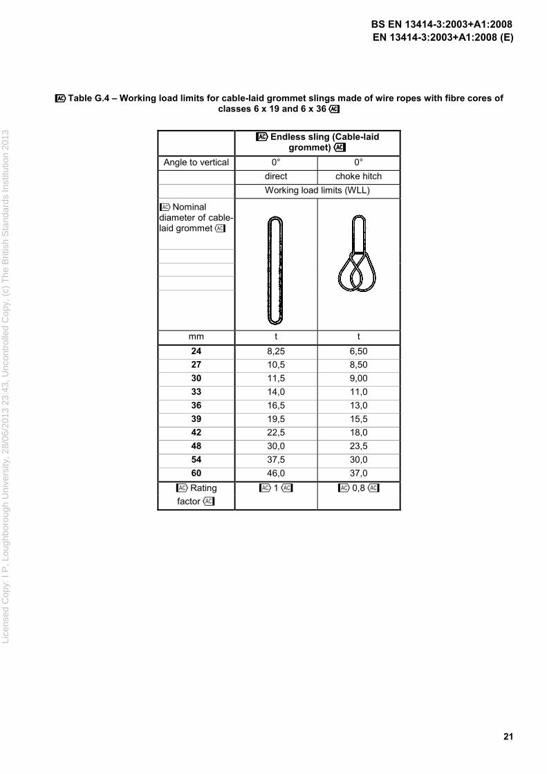
˜̃̃̃Table G.4 – Working load limits for cable-laid grommet slings made of wire ropes with fibre cores of classes 6 x 19 and 6 x 36™™™™
˜̃̃̃Endless sling (Cable-laid grommet)™™™™
Angle to vertical 0° 0°
direct choke hitch
Working load limits (WLL)
˜Nominal diameter of cable-laid grommet™
mm t t
24 8,25 6,50
27 10,5 8,50
30 11,5 9,00
33 14,0 11,0
36 16,5 13,0
39 19,5 15,5
42 22,5 18,0
48 30,0 23,5
54 37,5 30,0
60 46,0 37,0
˜1™ ˜0,8™ ˜Rating
factor™
BS EN 13414-3:2003+A1:2008
Lice
nsed
Cop
y: I
P, L
ough
boro
ugh
Uni
vers
ity, 2
8/06
/201
3 23
:43,
Unc
ontr
olle
d C
opy,
(c)
The
Brit
ish
Sta
ndar
ds In
stitu
tion
2013
EN 13414-3:2003+A1:2008 (E)
22
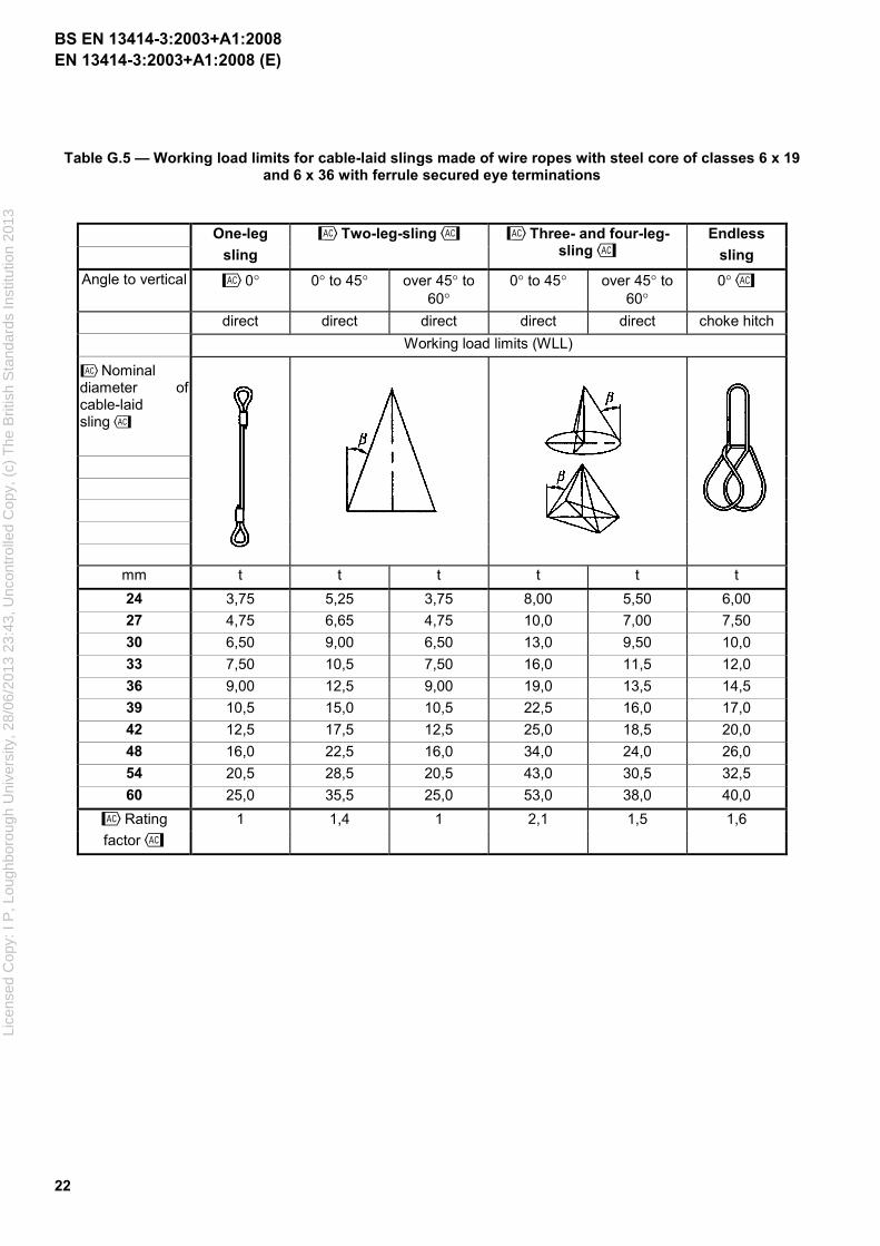
Table G.5 — Working load limits for cable-laid slings made of wire ropes with steel core of classes 6 x 19 and 6 x 36 with ferrule secured eye terminations
One-leg
sling
˜Two-leg-sling™ ˜Three- and four-leg-sling™
Endless
sling
Angle to vertical ˜0° 0° to 45° over 45° to 60°
0° to 45° over 45° to 60°
0°™
direct direct direct direct direct choke hitch
Working load limits (WLL)
˜Nominal diameter of cable-laid sling™
mm t t t t t t
24 3,75 5,25 3,75 8,00 5,50 6,00
27 4,75 6,65 4,75 10,0 7,00 7,50
30 6,50 9,00 6,50 13,0 9,50 10,0
33 7,50 10,5 7,50 16,0 11,5 12,0
36 9,00 12,5 9,00 19,0 13,5 14,5
39 10,5 15,0 10,5 22,5 16,0 17,0
42 12,5 17,5 12,5 25,0 18,5 20,0
48 16,0 22,5 16,0 34,0 24,0 26,0
54 20,5 28,5 20,5 43,0 30,5 32,5
60 25,0 35,5 25,0 53,0 38,0 40,0
˜Rating 1 1,4 1 2,1 1,5 1,6
factor™
BS EN 13414-3:2003+A1:2008
Lice
nsed
Cop
y: I
P, L
ough
boro
ugh
Uni
vers
ity, 2
8/06
/201
3 23
:43,
Unc
ontr
olle
d C
opy,
(c)
The
Brit
ish
Sta
ndar
ds In
stitu
tion
2013
EN 13414-3:2003+A1:2008 (E)
23
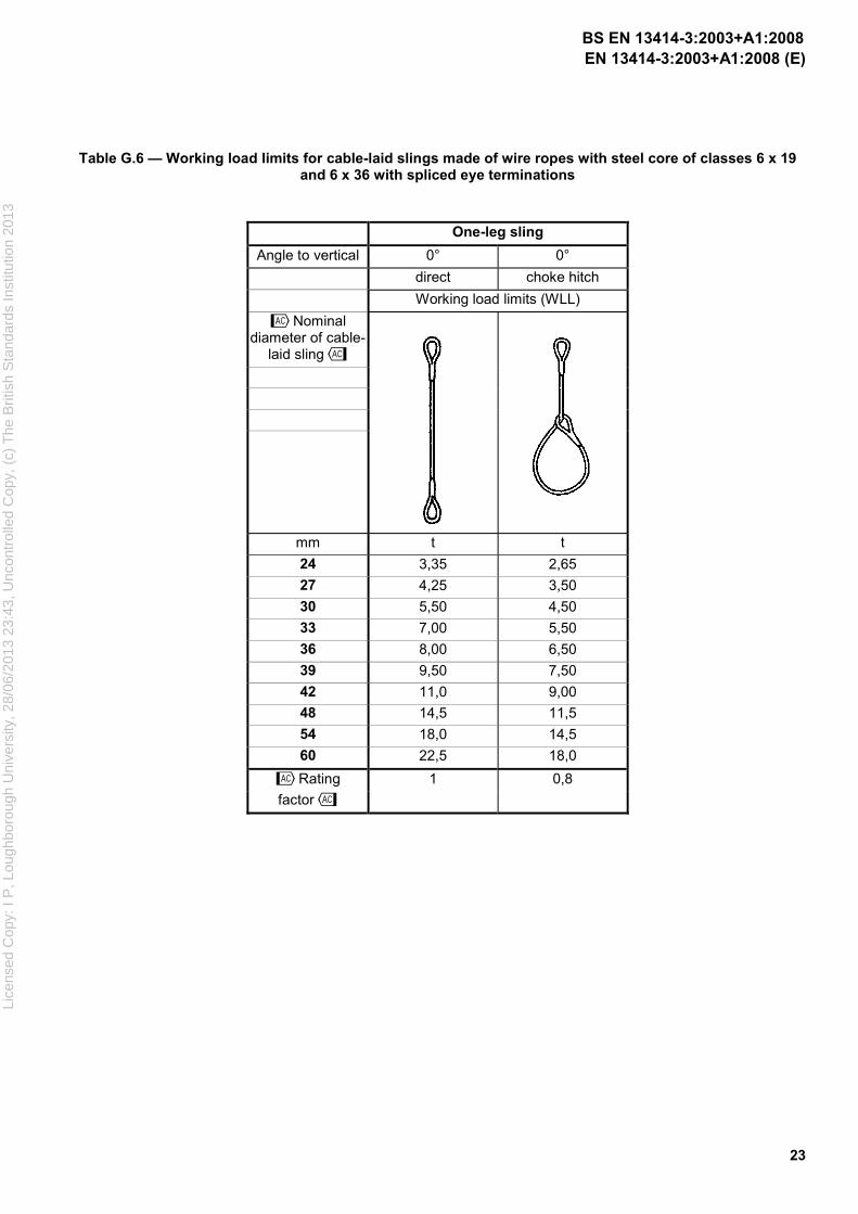
Table G.6 — Working load limits for cable-laid slings made of wire ropes with steel core of classes 6 x 19 and 6 x 36 with spliced eye terminations
One-leg sling
Angle to vertical 0° 0°
direct choke hitch
Working load limits (WLL)
˜Nominal diameter of cable-
laid sling™
mm t t
24 3,35 2,65
27 4,25 3,50
30 5,50 4,50
33 7,00 5,50
36 8,00 6,50
39 9,50 7,50
42 11,0 9,00
48 14,5 11,5
54 18,0 14,5
60 22,5 18,0
1 0,8 ˜Rating
factor™
BS EN 13414-3:2003+A1:2008
Lice
nsed
Cop
y: I
P, L
ough
boro
ugh
Uni
vers
ity, 2
8/06
/201
3 23
:43,
Unc
ontr
olle
d C
opy,
(c)
The
Brit
ish
Sta
ndar
ds In
stitu
tion
2013
EN 13414-3:2003+A1:2008 (E)
24
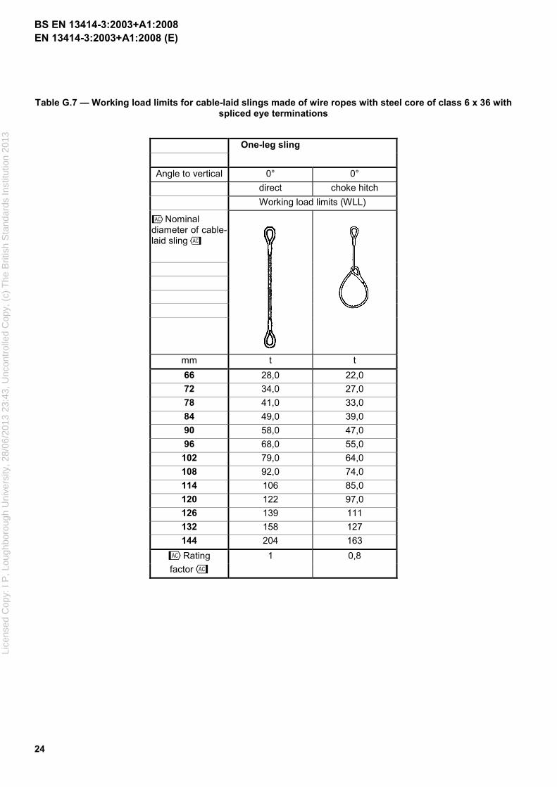
Table G.7 — Working load limits for cable-laid slings made of wire ropes with steel core of class 6 x 36 with spliced eye terminations
One-leg sling
Angle to vertical 0° 0°
direct choke hitch
Working load limits (WLL)
˜Nominal diameter of cable-laid sling™
mm t t
66 28,0 22,0
72 34,0 27,0
78 41,0 33,0
84 49,0 39,0
90 58,0 47,0
96 68,0 55,0
102 79,0 64,0
108 92,0 74,0
114 106 85,0
120 122 97,0
126 139 111
132 158 127
144 204 163
1 0,8 ˜Rating
factor™
BS EN 13414-3:2003+A1:2008
Lice
nsed
Cop
y: I
P, L
ough
boro
ugh
Uni
vers
ity, 2
8/06
/201
3 23
:43,
Unc
ontr
olle
d C
opy,
(c)
The
Brit
ish
Sta
ndar
ds In
stitu
tion
2013
EN 13414-3:2003+A1:2008 (E)
25
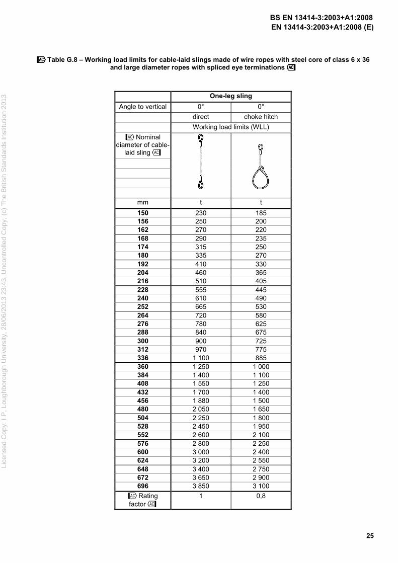
˜̃̃̃Table G.8 – Working load limits for cable-laid slings made of wire ropes with steel core of class 6 x 36 and large diameter ropes with spliced eye terminations™™™™
One-leg sling
Angle to vertical 0° 0°
direct choke hitch
Working load limits (WLL)
˜Nominal diameter of cable-
laid sling™
mm t t
150 230 185 156 250 200 162 270 220 168 290 235 174 315 250 180 335 270 192 410 330 204 460 365 216 510 405 228 555 445 240 610 490 252 665 530 264 720 580 276 780 625 288 840 675 300 900 725 312 970 775 336 1 100 885 360 1 250 1 000 384 1 400 1 100 408 1 550 1 250 432 1 700 1 400 456 1 880 1 500 480 2 050 1 650 504 2 250 1 800 528 2 450 1 950 552 2 600 2 100 576 2 800 2 250 600 3 000 2 400 624 3 200 2 550 648 3 400 2 750 672 3 650 2 900 696 3 850 3 100
˜Rating 1 0,8 factor™
BS EN 13414-3:2003+A1:2008
Lice
nsed
Cop
y: I
P, L
ough
boro
ugh
Uni
vers
ity, 2
8/06
/201
3 23
:43,
Unc
ontr
olle
d C
opy,
(c)
The
Brit
ish
Sta
ndar
ds In
stitu
tion
2013

EN 13414-3:2003+A1:2008 (E)
26
Annex ZA (informative)
!!!!Relationship between this European Standard and the Essential
Requirements of EU Directive 98/37/EC
This European Standard has been prepared under a mandate given to CEN by the European Commission and the European Free Trade Association to provide a means of conforming to Essential Requirements of the New Approach Directive 98/37/EC amended by 98/79/CE on machinery.
Once this standard is cited in the Official Journal of the European Communities under that Directive and has been implemented as a national standard in at least one Member State, compliance with the normative clauses of this standard confers, within the limits of the scope of this standard, a presumption of conformity with the relevant Essential Requirements of that Directive and associated EFTA regulations.
WARNING - Other requirements and other EU Directives may be applicable to the product(s) falling within the scope of this standard."
BS EN 13414-3:2003+A1:2008
Lice
nsed
Cop
y: I
P, L
ough
boro
ugh
Uni
vers
ity, 2
8/06
/201
3 23
:43,
Unc
ontr
olle
d C
opy,
(c)
The
Brit
ish
Sta
ndar
ds In
stitu
tion
2013

EN 13414-3:2003+A1:2008 (E)
27
Annex ZB (informative)
!!!!Relationship between this European Standard and the Essential
Requirements of EU Directive 2006/42/EC
This European Standard has been prepared under a mandate given to CEN by the European Commission and the European Free Trade Association to provide a means of conforming to Essential Requirements of the New Approach Directive 2006/42/EC on machinery.
Once this standard is cited in the Official Journal of the European Communities under that Directive and has been implemented as a national standard in at least one Member State, compliance with the normative clauses of this standard confers, within the limits of the scope of this standard, a presumption of conformity with the relevant Essential Requirements of that Directive and associated EFTA regulations.
WARNING - Other requirements and other EU Directives may be applicable to the product(s) falling within the scope of this standard."
BS EN 13414-3:2003+A1:2008
Lice
nsed
Cop
y: I
P, L
ough
boro
ugh
Uni
vers
ity, 2
8/06
/201
3 23
:43,
Unc
ontr
olle
d C
opy,
(c)
The
Brit
ish
Sta
ndar
ds In
stitu
tion
2013

BSI Group Headquarters
389 Chiswick High Road,
London W4 4AL, UK
Tel +44 (0)20 8996 9001
Fax +44 (0)20 8996 7001
www.bsigroup.com/standards
British Standards Institution (BSI)
BSI is the independent national body responsible for preparing
British Standards. It presents the UK view on standards in Europe and at the
international level. It is incorporated by Royal Charter.
Revisions
British Standards are updated by amendment or revision. Users of
British Standards should make sure that they possess the latest amendments or
editions.
It is the constant aim of BSI to improve the quality of our products and services.
We would be grateful if anyone finding an inaccuracy or ambiguity while using
this British Standard would inform the Secretary of the technical committee
responsible, the identity of which can be found on the inside front cover.
Tel: +44 (0)20 8996 9000 Fax: +44 (0)20 8996 7400
BSI offers members an individual updating service called PLUS which ensures
that subscribers automatically receive the latest editions of standards.
Buying standards
Orders for all BSI, international and foreign standards publications should be
addressed to Customer Services.
Tel: +44 (0)20 8996 9001 Fax: +44 (0)20 8996 7001
Email: [email protected]
You may also buy directly using a debit/credit card from the BSI Shop on the
Website http://www.bsigroup.com/shop.
In response to orders for international standards, it is BSI policy to supply the
BSI implementation of those that have been published as British Standards,
unless otherwise requested.
Information on standards
BSI provides a wide range of information on national, European and
international standards through its Library and its Technical Help to Exporters
Service. Various BSI electronic information services are also available which give
details on all its products and services. Contact the Information Centre.
Tel: +44 (0)20 8996 7111 Fax: +44 (0)20 8996 7048
Email: [email protected]
Subscribing members of BSI are kept up to date with standards developments
and receive substantial discounts on the purchase price of standards. For details
of these and other benefits contact Membership Administration.
Tel: +44 (0)20 8996 7002 Fax: +44 (0)20 8996 7001
Email: [email protected]
Information regarding online access to British Standards via British Standards
Online can be found at http://www.bsigroup.com/BSOL.
Further information about BSI is available on the BSI website at
http://www.bsigroup.com.
Copyright
Copyright subsists in all BSI publications. BSI also holds the copyright, in the
UK, of the publications of the international standardization bodies. Except as
permitted under the Copyright, Designs and Patents Act 1988 no extract may be
reproduced, stored in a retrieval system or transmitted in any form or by any
means – electronic, photocopying, recording or otherwise – without prior written
permission from BSI.
This does not preclude the free use, in the course of implementing the standard,
of necessary details such as symbols, and size, type or grade designations. If these
details are to be used for any other purpose than implementation then the prior
written permission of BSI must be obtained.
Details and advice can be obtained from the Copyright & Licensing Manager.
Tel: +44 (0)20 8996 7070 Email: [email protected]
BSEN
13414-3:2003+A1:2008
Lice
nsed
Cop
y: I
P, L
ough
boro
ugh
Uni
vers
ity, 2
8/06
/201
3 23
:43,
Unc
ontr
olle
d C
opy,
(c)
The
Brit
ish
Sta
ndar
ds In
stitu
tion
2013