Embed Size (px)
DESCRIPTION
composites
Citation preview
TiB2 reinforced aluminum based in situ composites fabricatedby stir casting
Fei Chen a, Zongning Chen b, Feng Mao a, Tongmin Wang a,n, Zhiqiang Cao b,nn
a Key Laboratory of Materials Modification by Laser, Ion, and Electron Beams (Ministry of Education), School of Materials Science and Engineering,Dalian University of Technology, Dalian 116024, Chinab Laboratory of Special Processing of Raw Materials, Dalian University of Technology, Dalian 116024, PR China
a r t i c l e i n f o
Article history:Received 22 August 2014Received in revised form4 December 2014Accepted 8 December 2014Available online 18 December 2014
Keywords:TiB2 particlesIn situ compositesStirringTomographyMicrostructureMechanical properties
a b s t r a c t
In this study, a new technique involving mechanical stirring at the salts/aluminum interface wasdeveloped to fabricate TiB2 particulate reinforced aluminum based in situ composites with improvedparticle distribution. Processing parameters in terms of stirring intensity, stirring duration and stirringstart time were optimized according to the microstructure and mechanical properties evaluation. Theresults show that, the first and last 15 min of the entire 60 min holding are of prime importance to theparticle distribution of the final composites. When applying 180 rpm (revolutions per minute) stirring atthe salts/aluminum interface in these two intervals, a more uniform microstructure can be achieved andthe Al-4 wt% TiB2 composite thus produced exhibits superior mechanical performance. Synchrotronradiation X-ray computed tomography (SR-CT) was used to give a full-scale imaging of the particledistribution. From the SR-CT results, the in situ Al–xTiB2 composites (x¼1, 4 and 7, all in wt%) fabricatedby the present technique are characterized by fine and clean TiB2 particles distributed uniformlythroughout the Al matrix. These composites not only have higher yield strength (σ0.2) and ultimatetensile strength (UTS), but also exhibit superior ductility, with respect to the Al–TiB2 compositesfabricated by the conventional process. The σ0.2 and UTS of the Al–7TiB2 composite in the present work,are 260% and 180% higher than those of the matrix. A combined mechanism was also presented tointerpret the improvements in yield strength of the composites as influenced by their microstructuresand processing history. The predicted values are in good agreement with the experimental results,strongly supporting the strengthening mechanism we proposed. Fractography reveals that the compo-sites thus fabricated, follow ductile fracture mechanism in spite of the presence of stiff reinforcements.
& 2014 Elsevier B.V. All rights reserved.
1. Introduction
Al based metal matrix composites (MMCs) reinforced withceramic particles have received extensive attention due to theirhigh specific strength-to-weight ratio, good wear resistance,excellent dimensional stability and superior damping capacity incomparison with the matrix alloy [1,2]. The conventional practiceto prepare Al based composites (ex situ composites) involves theaddition of externally synthesized reinforcements, such as SiC,Al2O3 and TiC, to the matrix alloys [3–5]. This process, however,could lead to segregation and thermodynamic instability of thereinforcements, and poor adhesion at the interface, unless theceramic particles have been suitably modified [6,7].
To overcome these drawbacks often occasioned in the prepara-tion of ex situ MMCs, in situ techniques have been greatlydeveloped in recent years. Since the formation of the reinforce-ments takes place within the matrix, in situ synthesized MMCsprovide advantages including uniform distribution of finer parti-cles, excellent bonding at the matrix/reinforcement interface,thermodynamical stability of the reinforcements and processeconomy [8,9].
A wide variety of in situ formed ceramic particulates, such asAl2O3, TiB2 and TiC, have been used as reinforcements to fabricateAl based MMCs [10,11]. Among these particulates, TiB2 is anadvanced strengthening phase for Al matrix as it possesses adesirable combination of physical and mechanical properties,including high melting point (3225 1C), high elastic modulus(534 GPa), high hardness (3400 HV) and outstanding wear resis-tance. More importantly, it does not react with Al to form anydetrimental reaction products at the matrix/reinforcement inter-face [7,12]. In the past two decades, numerous studies have beenconducted to develop new fabrication processes of TiB2 reinforced
Contents lists available at ScienceDirect
journal homepage: www.elsevier.com/locate/msea
Materials Science & Engineering A
http://dx.doi.org/10.1016/j.msea.2014.12.0330921-5093/& 2014 Elsevier B.V. All rights reserved.
n Corresponding author. Tel.: þ86 411 84706790; fax: þ86 41184706790.nn Corresponding author. Tel.: þ86 411 84706169; fax: þ86 411 8470616.E-mail addresses: [email protected] (T. Wang), [email protected] (Z. Cao).
Materials Science & Engineering A 625 (2015) 357–368
in situ Al based MMCs with improved wear performance, mechan-ical properties and damping capacity [6,13,14].
Although the TiB2 reinforced in situ Al based composites haveprominent advantages, their microstructure and mechanical prop-erties are known to be highly sensitive to the processing para-meters in the production. Reinforcement segregation and residualintermediate products, such as TiAl3 and AlB2, are frequentlypresent in the final composites [15–17]. These defects have beenfound to act as preferential sites for crack initiation and propaga-tion. Therefore, elimination of these defects is regarded as aprimary concern to prepare Al–TiB2 composites with consistentproperties [18,19].
In the present study, the stir casting technique, a conventionalmethod to prepare ex situ MMCs [20,21], was elaborately modifiedto fabricate TiB2 reinforced in situ Al based MMCs using the halidesalt route. In this process, a well-designed device was applied tostirring at the salts/aluminum interface, based on the fact that thereactions, by which TiB2 is formed, generally take place in thevicinity of the salts/aluminum interface. The effects of processingparameters, i.e. stirring speed, stirring duration, and stirring starttime on the microstructure and mechanical properties of the finalproducts have been studied in detail.
Furthermore, synchrotron radiation X-ray computed tomogra-phy (SR-CT) has been used to investigate the particle distributionof the experimental Al–TiB2 composites from three dimensional(3D) view, since the third-generation synchrotron radiation (SR)source has been reported being able to offer a unique opportunityto non-destructively observe the microstructural characteristics ofmetallic materials with submicron spatial resolution [22,23].However, in the conventional 2D (two dimensional) measure-ments, such as, optical and scanning electron microscope analysis,materials microstructure is likely to be destroyed during samplepreparation (cutting, polishing and etching) [24–26]. The aim ofthe present work is to explore the feasibility of fabricating low costAl based composites with improved mechanical properties, inaddition, to enlarge the application of synchrotron radiation inthe field of MMCs.
2. Experimental procedures
Al–TiB2 in situ composites were synthesized by the exothermicreaction of halide salts (KBF4–K2TiF6) with molten aluminumaccording to the following reactions:
3K2TiF6þ13Al-3KAlF4þK3AlF6þ3TiAl3 (1)
2KBF4þ3Al-2KAlF4þAlB2 (2)
TiAl3þAlB2-TiB2þ4Al (3)
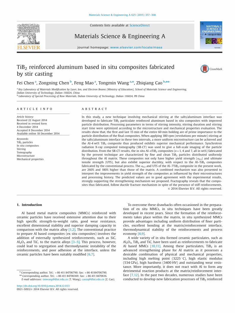
Commercially available Al (99.8% Al: all compositions are inmass fraction unless stated otherwise), KBF4 and K2TiF6 powdersof analytical purity (99% purity) were used as starting materials.Fig. 1 shows the schematic diagram of the set-up for fabricatingAl–TiB2 in situ composites. For each experiment, 1.5 kg Al wasmelted and heated to 86075 1C in a graphite–clay crucible underambient atmospheres, using a resistance furnace. The pre-dried(200 1C for 2 h) K2TiF6 and KBF4 mixture with a stoichiometric Ti/Bratio of 1:2 was then added into the melt. After salts melted, apreheated impeller with four straight blades was employed tostirring at the salts/aluminum interface. The straight blades of theimpeller, which could reduce the inclusion of post-reaction slag,were made of graphite due to the fact that graphite will notcontaminate both of the molten salts and molten aluminum.Moreover, it has been demonstrated that carbon plays a positiverole in the formation of TiB2.
The stirring intensity (60, 180 and 300 rpm (revolutions perminute)), stirring duration (5, 15, 30 and 60 min) and stirring starttime (initial, middle and later) were varied to investigate theeffects of stirring parameters on the microstructures and mechan-ical performances of the Al–4% TiB2 composites. The melt was heldat 860 1C for 60 min to enable the reactions to achieve completion.After decanting by-product K–Al–F salts and degassing for oneminute by high-purity argon, the melt of 700 1C was poured into apreheated (200 1C) permanent mold. Composites with 1% and 7%TiB2 were also fabricated under the optimized process condition toinvestigate the feasibility of the technique in producing compo-sites with different particle contents.
Phase identification of the composites was performed by anX-ray diffractometer (Empyrean) using Cu-Kα radiation operatedat 40 kV and 40 mA. For microstructure analysis, the specimenswere polished and etched with Keller's reagent, then examined bya field emission scanning electron microscope (SEM) equippedwith an energy dispersive spectrometer (EDS).
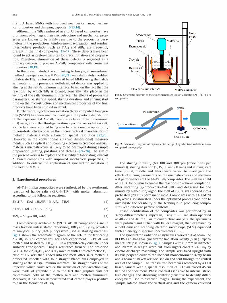
The synchrotron radiation analysis was carried out at beam lineBL13W1 at Shanghai Synchrotron Radiation Facility (SSRF). Experi-mental setup is shown in Fig. 2. Samples with 0.7 mm in diameterand 20 mm in length were cut from ingots contain 7% TiB2 byelectro discharge machining. The sample was fixed upright withits axis perpendicular to the incident monochromatic X-ray beamand a beam of 18 keV was focused on and sent through the centralarea of the sample. The transmitted beam was recorded by a CCDbased camera with a spatial resolution of 0.37 μm placed 45 cmbehind the specimens. Phase contrast (sensitive to internal struc-ture change), and absorbing contrast (sensitive to density differ-ence) were used to establish images. During the experiment, thesample rotated about the vertical axis and the camera collected
Fig. 1. Schematic diagram of the experimental set-up for fabricating Al–TiB2 in situcomposites.
Fig. 2. Schematic diagram of experimental setup of synchrotron radiation X-raycomputed tomography.
F. Chen et al. / Materials Science & Engineering A 625 (2015) 357–368358
the image data continuously with exposure time per frame was2 s. A total of 1048 images were used to reconstruction threedimensions (3D) structure of the composites.
Hardness tests of the composites were carried out using aBrinell hardness tester. The tensile specimens with a gauge lengthof 30 mm, a gauge diameter of 6 mm were prepared according toASTM E8M-04 standard. The yield strength (σ0.2) and ultimatetensile strength (UTS) were estimated using a computerizeduniversal testing machine. The tensile velocity was 0.05 mm/s.Three tests were conducted for each composite to get a precisevalue for each property. Fracture surfaces were analyzed usingSEM to evaluate the fracture mechanism.
3. Results and discussion
3.1. Stirring intensity
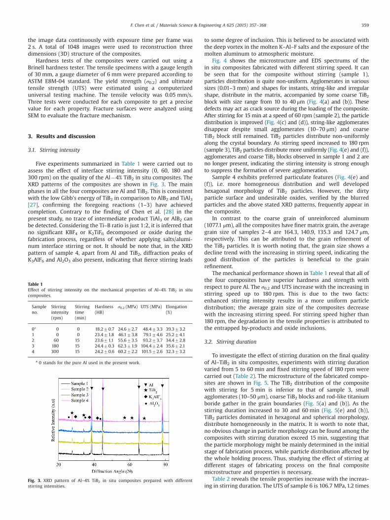
Five experiments summarized in Table 1 were carried out toassess the effect of interface stirring intensity (0, 60, 180 and300 rpm) on the quality of the Al�4% TiB2 in situ composites. TheXRD patterns of the composites are shown in Fig. 3. The mainphases in all the four composites are Al and TiB2. This is consistentwith the low Gibb's energy of TiB2 in comparison to AlB2 and TiAl3[27], confirming the foregoing reactions (1–3) have achievedcompletion. Contrary to the finding of Chen et al. [28] in thepresent study, no trace of intermediate product TiAl3 or AlB2 canbe detected. Considering the Ti–B ratio is just 1:2, it is inferred thatno significant KBF4 or K2TiF6 decomposed or oxide during thefabrication process, regardless of whether applying salts/alumi-num interface stirring or not. It should be note that, in the XRDpattern of sample 4, apart from Al and TiB2, diffraction peaks ofK3AlF6 and Al2O3 also present, indicating that fierce stirring leads
to some degree of inclusion. This is believed to be associated withthe deep vortex in the molten K–Al–F salts and the exposure of themolten aluminum to atmospheric moisture.
Fig. 4 shows the microstructure and EDS spectrums of thein situ composites fabricated with different stirring speed. It canbe seen that for the composite without stirring (sample 1),particles distribution is quite non-uniform. Agglomerates in varioussizes (0.01–3 mm) and shapes for instants, string-like and irregularshape, distribute in the matrix, accompanied by some coarse TiB2block with size range from 10 to 40 μm (Fig. 4(a) and (b)). Thesedefects may act as crack source during the loading of the composite.After stirring for 15 min at a speed of 60 rpm (sample 2), the particledistribution is improved (Fig. 4(c) and (d)), string-like agglomeratesdisappear despite small agglomerates (10–70 μm) and coarseTiB2 block still remained. TiB2 particles distribute non-uniformlyalong the crystal boundary. As stirring speed increased to 180 rpm(sample 3), TiB2 particles distribute more uniformly (Fig. 4(e) and (f)),agglomerates and coarse TiB2 blocks observed in sample 1 and 2 areno longer present, indicating the stirring intensity is strong enoughto suppress the formation of severe agglomeration.
Sample 4 exhibits preferred particulate features (Fig. 4(e) and(f)), i.e. more homogeneous distribution and well developedhexagonal morphology of TiB2 particles. However, the dirtyparticle surface and undesirable oxides, verified by the blurredparticles and the above stated XRD patterns, frequently appear inthe composite.
In contrast to the coarse grain of unreinforced aluminum(1077.1 μm), all the composites have finer matrix grain, the averagegrain size of samples 2–4 are 164.3, 140.9, 135.3 and 124.7 μm,respectively. This can be attributed to the grain refinement ofthe TiB2 particles. It is worth noting that, the grain size shows adecline trend with the increasing in stirring speed, indicating thegood distribution of the particles is beneficial to the grainrefinement.
The mechanical performance shown in Table 1 reveal that all ofthe four composites have superior hardness and strength withrespect to pure Al. The σ0.2 and UTS increase with the increasing instirring speed up to 180 rpm. This is due to the two facts:enhanced stirring intensity results in a more uniform particledistribution; the average grain size of the composites decreasewith the increasing stirring speed. For stirring speed higher than180 rpm, the degradation in the tensile properties is attributed tothe entrapped by-products and oxide inclusions.
3.2. Stirring duration
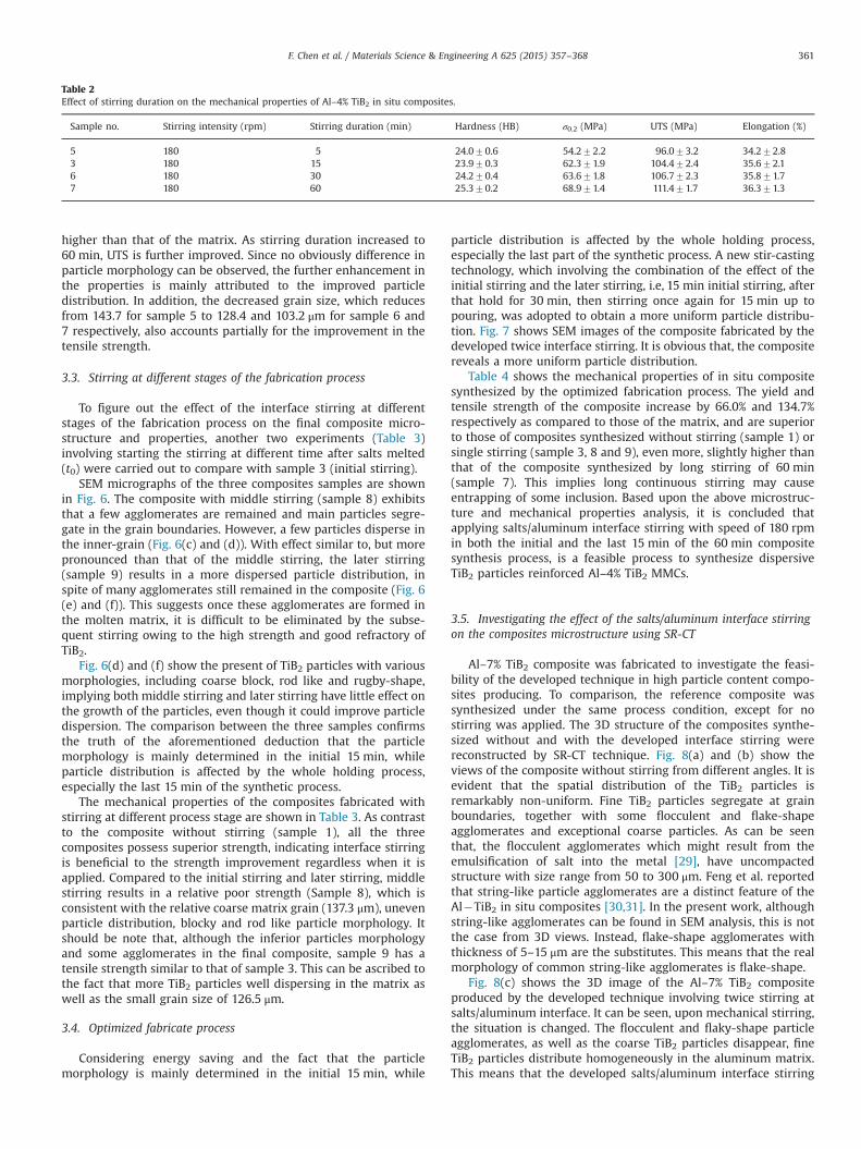
To investigate the effect of stirring duration on the final qualityof Al–TiB2 in situ composites, experiments with stirring durationvaried from 5 to 60 min and fixed stirring speed of 180 rpm werecarried out (Table 2). The microstructure of the fabricated compo-sites are shown in Fig. 5. The TiB2 distribution of the compositewith stirring for 5 min is inferior to that of sample 3, smallagglomerates (10–50 μm), coarse TiB2 blocks and rod-like titaniumboride gather in the grain boundaries (Fig. 5(a) and (b)). As thestirring duration increased to 30 and 60 min (Fig. 5(e) and (h)),TiB2 particles dominated in hexagonal and spherical morphology,distribute homogeneously in the matrix. It is worth to note that,no obvious change in particle morphology can be found among thecomposites with stirring duration exceed 15 min, suggesting thatthe particle morphology might be mainly determined in the initialstage of fabrication process, while particle distribution affected bythe whole holding process. Thus, studying the effect of stirring atdifferent stages of fabricating process on the final compositemicrostructure and properties is necessary.
Table 2 reveals the tensile properties increase with the increas-ing in stirring duration. The UTS of sample 6 is 106.7 MPa, 1.2 times
Table 1Effect of stirring intensity on the mechanical properties of Al–4% TiB2 in situcomposites.
Sampleno.
Stirringintensity(rpm)
Stirringtime(min)
Hardness(HB)
σ0.2 (MPa) UTS (MPa) Elongation(%)
0a 0 0 18.270.7 24.672.7 48.473.3 39.373.21 0 0 23.471.8 46.173.8 79.174.6 25.274.12 60 15 23.671.1 55.673.5 93.273.7 34.472.83 180 15 24.470.3 62.371.9 104.472.4 35.672.14 300 15 24.270.6 60.272.2 101.572.6 32.373.2
a 0 stands for the pure Al used in the present work.
Fig. 3. XRD pattern of Al–4% TiB2 in situ composites prepared with differentstirring intensities.
F. Chen et al. / Materials Science & Engineering A 625 (2015) 357–368 359
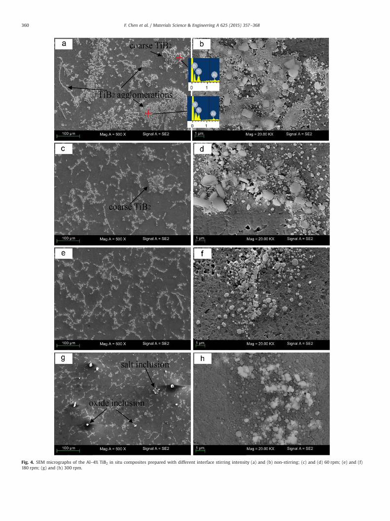
Fig. 4. SEM micrographs of the Al–4% TiB2 in situ composites prepared with different interface stirring intensity (a) and (b) non-stirring; (c) and (d) 60 rpm; (e) and (f)180 rpm; (g) and (h) 300 rpm.
F. Chen et al. / Materials Science & Engineering A 625 (2015) 357–368360
higher than that of the matrix. As stirring duration increased to60 min, UTS is further improved. Since no obviously difference inparticle morphology can be observed, the further enhancement inthe properties is mainly attributed to the improved particledistribution. In addition, the decreased grain size, which reducesfrom 143.7 for sample 5 to 128.4 and 103.2 μm for sample 6 and7 respectively, also accounts partially for the improvement in thetensile strength.
3.3. Stirring at different stages of the fabrication process
To figure out the effect of the interface stirring at differentstages of the fabrication process on the final composite micro-structure and properties, another two experiments (Table 3)involving starting the stirring at different time after salts melted(t0) were carried out to compare with sample 3 (initial stirring).
SEM micrographs of the three composites samples are shownin Fig. 6. The composite with middle stirring (sample 8) exhibitsthat a few agglomerates are remained and main particles segre-gate in the grain boundaries. However, a few particles disperse inthe inner-grain (Fig. 6(c) and (d)). With effect similar to, but morepronounced than that of the middle stirring, the later stirring(sample 9) results in a more dispersed particle distribution, inspite of many agglomerates still remained in the composite (Fig. 6(e) and (f)). This suggests once these agglomerates are formed inthe molten matrix, it is difficult to be eliminated by the subse-quent stirring owing to the high strength and good refractory ofTiB2.
Fig. 6(d) and (f) show the present of TiB2 particles with variousmorphologies, including coarse block, rod like and rugby-shape,implying both middle stirring and later stirring have little effect onthe growth of the particles, even though it could improve particledispersion. The comparison between the three samples confirmsthe truth of the aforementioned deduction that the particlemorphology is mainly determined in the initial 15 min, whileparticle distribution is affected by the whole holding process,especially the last 15 min of the synthetic process.
The mechanical properties of the composites fabricated withstirring at different process stage are shown in Table 3. As contrastto the composite without stirring (sample 1), all the threecomposites possess superior strength, indicating interface stirringis beneficial to the strength improvement regardless when it isapplied. Compared to the initial stirring and later stirring, middlestirring results in a relative poor strength (Sample 8), which isconsistent with the relative coarse matrix grain (137.3 μm), unevenparticle distribution, blocky and rod like particle morphology. Itshould be note that, although the inferior particles morphologyand some agglomerates in the final composite, sample 9 has atensile strength similar to that of sample 3. This can be ascribed tothe fact that more TiB2 particles well dispersing in the matrix aswell as the small grain size of 126.5 μm.
3.4. Optimized fabricate process
Considering energy saving and the fact that the particlemorphology is mainly determined in the initial 15 min, while
particle distribution is affected by the whole holding process,especially the last part of the synthetic process. A new stir-castingtechnology, which involving the combination of the effect of theinitial stirring and the later stirring, i.e, 15 min initial stirring, afterthat hold for 30 min, then stirring once again for 15 min up topouring, was adopted to obtain a more uniform particle distribu-tion. Fig. 7 shows SEM images of the composite fabricated by thedeveloped twice interface stirring. It is obvious that, the compositereveals a more uniform particle distribution.
Table 4 shows the mechanical properties of in situ compositesynthesized by the optimized fabrication process. The yield andtensile strength of the composite increase by 66.0% and 134.7%respectively as compared to those of the matrix, and are superiorto those of composites synthesized without stirring (sample 1) orsingle stirring (sample 3, 8 and 9), even more, slightly higher thanthat of the composite synthesized by long stirring of 60 min(sample 7). This implies long continuous stirring may causeentrapping of some inclusion. Based upon the above microstruc-ture and mechanical properties analysis, it is concluded thatapplying salts/aluminum interface stirring with speed of 180 rpmin both the initial and the last 15 min of the 60 min compositesynthesis process, is a feasible process to synthesize dispersiveTiB2 particles reinforced Al–4% TiB2 MMCs.
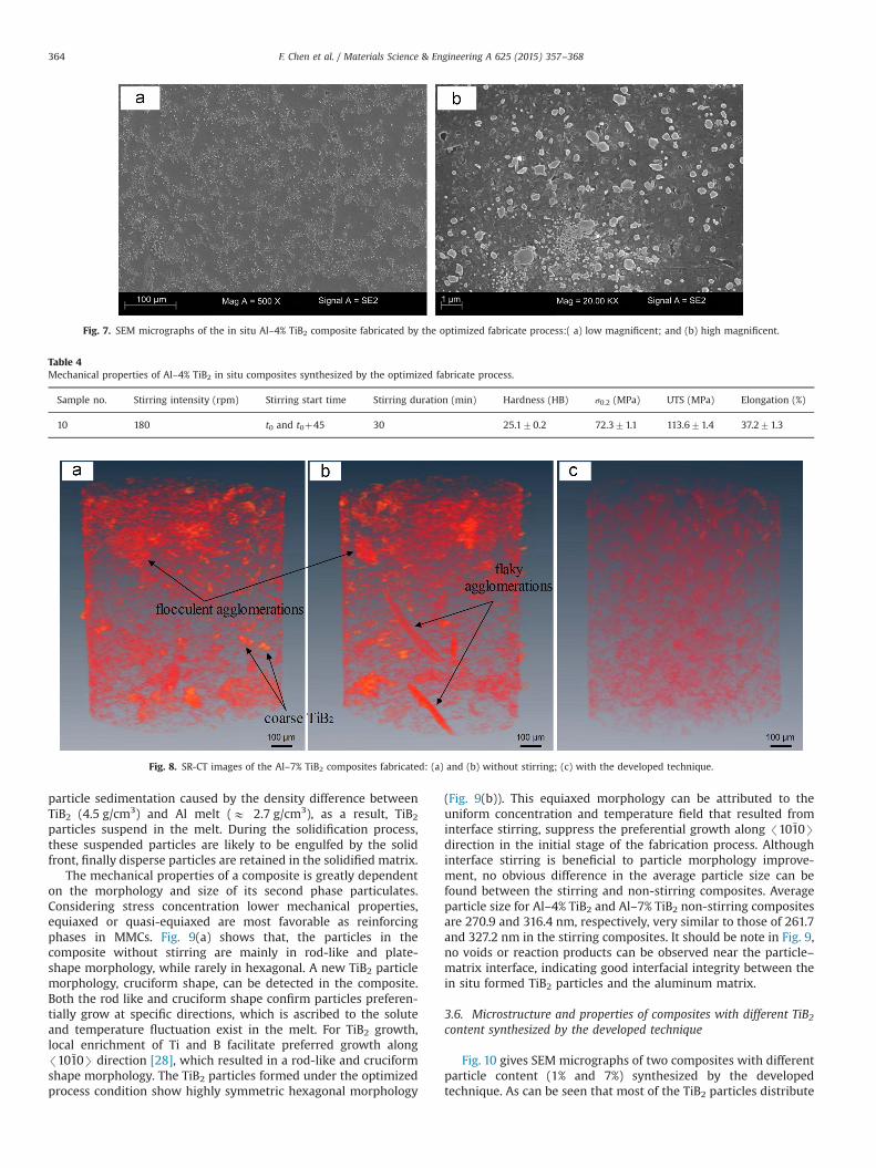
3.5. Investigating the effect of the salts/aluminum interface stirringon the composites microstructure using SR-CT
Al–7% TiB2 composite was fabricated to investigate the feasi-bility of the developed technique in high particle content compo-sites producing. To comparison, the reference composite wassynthesized under the same process condition, except for nostirring was applied. The 3D structure of the composites synthe-sized without and with the developed interface stirring werereconstructed by SR-CT technique. Fig. 8(a) and (b) show theviews of the composite without stirring from different angles. It isevident that the spatial distribution of the TiB2 particles isremarkably non-uniform. Fine TiB2 particles segregate at grainboundaries, together with some flocculent and flake-shapeagglomerates and exceptional coarse particles. As can be seenthat, the flocculent agglomerates which might result from theemulsification of salt into the metal [29], have uncompactedstructure with size range from 50 to 300 μm. Feng et al. reportedthat string-like particle agglomerates are a distinct feature of theAl�TiB2 in situ composites [30,31]. In the present work, althoughstring-like agglomerates can be found in SEM analysis, this is notthe case from 3D views. Instead, flake-shape agglomerates withthickness of 5–15 μm are the substitutes. This means that the realmorphology of common string-like agglomerates is flake-shape.
Fig. 8(c) shows the 3D image of the Al–7% TiB2 compositeproduced by the developed technique involving twice stirring atsalts/aluminum interface. It can be seen, upon mechanical stirring,the situation is changed. The flocculent and flaky-shape particleagglomerates, as well as the coarse TiB2 particles disappear, fineTiB2 particles distribute homogeneously in the aluminum matrix.This means that the developed salts/aluminum interface stirring
Table 2Effect of stirring duration on the mechanical properties of Al–4% TiB2 in situ composites.
Sample no. Stirring intensity (rpm) Stirring duration (min) Hardness (HB) σ0.2 (MPa) UTS (MPa) Elongation (%)
5 180 5 24.070.6 54.272.2 96.073.2 34.272.83 180 15 23.970.3 62.371.9 104.472.4 35.672.16 180 30 24.270.4 63.671.8 106.772.3 35.871.77 180 60 25.370.2 68.971.4 111.471.7 36.371.3
F. Chen et al. / Materials Science & Engineering A 625 (2015) 357–368 361
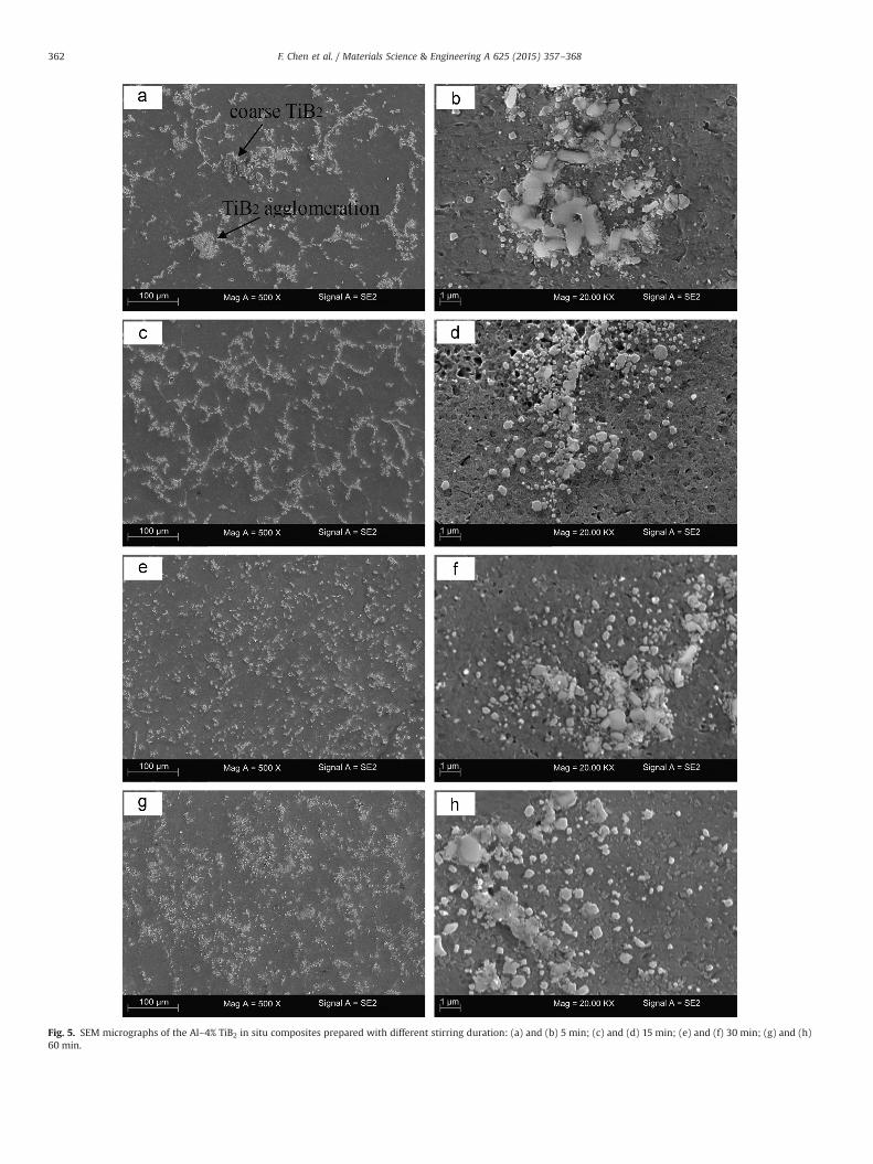
Fig. 5. SEM micrographs of the Al–4% TiB2 in situ composites prepared with different stirring duration: (a) and (b) 5 min; (c) and (d) 15 min; (e) and (f) 30 min; (g) and (h)60 min.
F. Chen et al. / Materials Science & Engineering A 625 (2015) 357–368362
technique is effective in synthesizing high content TiB2 reinforcedMMCs.
Interface mechanical stirring improves TiB2 particles distribu-tion by two means. One is preventing the formation of variousagglomerates: enhancing diffusion at the salts/aluminum inter-face, not only suppresses the nucleation and growth of coarse AlB2
and TiAl3 intermetallic compounds, but also constrains the
formation and deposition of large engulf-salt droplets; in addition,velocity gradient exists in the flowing fluid owning to the viscosityof the melt, therefore, flowing liquids scour the surface of existingcompounds and engulf-salt, accelerates the elements diffusion anddisperse TiB2 seeds into the bulk molten pool. The other effect isresisting the sedimentation of the already formed particles. Twiceinterface stirring, especially the later stirring, overcomes the
Table 3Effect of stirring at different process stages on the mechanical properties of Al–4% TiB2 in situ composites.
Sample no. Stirring intensity (rpm) Stirring start time (min) Stirring duration (min) Hardness (HB) σ0.2 (MPa) UTS (MPa) Elongation (%)
3 180 t0 15 23.970.4 62.371.9 104.472.4 35.672.18 180 t0þ15 15 22.570.6 59.872.5 96.372.8 32.972.99 180 t0þ45 15 23.370.3 66.571.4 102.671.8 36.271.7
Fig. 6. SEM micrographs of the Al–4% TiB2 composites fabricated by applying interface stirring at different time after salts melted: (a) t0 (initial stirring); (b) t0þ15 (middlestirring); (c) t0þ45 min (later stirring).
F. Chen et al. / Materials Science & Engineering A 625 (2015) 357–368 363
particle sedimentation caused by the density difference betweenTiB2 (4.5 g/cm3) and Al melt (E 2.7 g/cm3), as a result, TiB2particles suspend in the melt. During the solidification process,these suspended particles are likely to be engulfed by the solidfront, finally disperse particles are retained in the solidified matrix.
The mechanical properties of a composite is greatly dependenton the morphology and size of its second phase particulates.Considering stress concentration lower mechanical properties,equiaxed or quasi-equiaxed are most favorable as reinforcingphases in MMCs. Fig. 9(a) shows that, the particles in thecomposite without stirring are mainly in rod-like and plate-shape morphology, while rarely in hexagonal. A new TiB2 particlemorphology, cruciform shape, can be detected in the composite.Both the rod like and cruciform shape confirm particles preferen-tially grow at specific directions, which is ascribed to the soluteand temperature fluctuation exist in the melt. For TiB2 growth,local enrichment of Ti and B facilitate preferred growth along/101̄0S direction [28], which resulted in a rod-like and cruciformshape morphology. The TiB2 particles formed under the optimizedprocess condition show highly symmetric hexagonal morphology
(Fig. 9(b)). This equiaxed morphology can be attributed to theuniform concentration and temperature field that resulted frominterface stirring, suppress the preferential growth along /101̄0Sdirection in the initial stage of the fabrication process. Althoughinterface stirring is beneficial to particle morphology improve-ment, no obvious difference in the average particle size can befound between the stirring and non-stirring composites. Averageparticle size for Al–4% TiB2 and Al–7% TiB2 non-stirring compositesare 270.9 and 316.4 nm, respectively, very similar to those of 261.7and 327.2 nm in the stirring composites. It should be note in Fig. 9,no voids or reaction products can be observed near the particle–matrix interface, indicating good interfacial integrity between thein situ formed TiB2 particles and the aluminum matrix.
3.6. Microstructure and properties of composites with different TiB2content synthesized by the developed technique
Fig. 10 gives SEM micrographs of two composites with differentparticle content (1% and 7%) synthesized by the developedtechnique. As can be seen that most of the TiB2 particles distribute
Fig. 7. SEM micrographs of the in situ Al–4% TiB2 composite fabricated by the optimized fabricate process:( a) low magnificent; and (b) high magnificent.
Table 4Mechanical properties of Al–4% TiB2 in situ composites synthesized by the optimized fabricate process.
Sample no. Stirring intensity (rpm) Stirring start time Stirring duration (min) Hardness (HB) σ0.2 (MPa) UTS (MPa) Elongation (%)
10 180 t0 and t0þ45 30 25.170.2 72.371.1 113.671.4 37.271.3
Fig. 8. SR-CT images of the Al–7% TiB2 composites fabricated: (a) and (b) without stirring; (c) with the developed technique.
F. Chen et al. / Materials Science & Engineering A 625 (2015) 357–368364
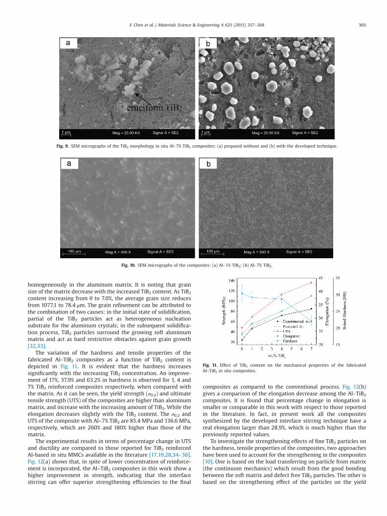
homogeneously in the aluminum matrix. It is noting that grainsize of the matrix decrease with the increased TiB2 content. As TiB2
content increasing from 0 to 7.0%, the average grain size reducesfrom 1077.1 to 78.4 μm. The grain refinement can be attributed tothe combination of two causes: in the initial state of solidification,partial of the TiB2 particles act as heterogeneous nucleationsubstrate for the aluminum crystals; in the subsequent solidifica-tion process, TiB2 particles surround the growing soft aluminummatrix and act as hard restrictive obstacles against grain growth[32,33].
The variation of the hardness and tensile properties of thefabricated Al–TiB2 composites as a function of TiB2 content isdepicted in Fig. 11. It is evident that the hardness increasessignificantly with the increasing TiB2 concentration. An improve-ment of 17%, 37.9% and 63.2% in hardness is observed for 1, 4 and7% TiB2 reinforced composites respectively, when compared withthe matrix. As it can be seen, the yield strength (σ0.2) and ultimatetensile strength (UTS) of the composites are higher than aluminummatrix, and increase with the increasing amount of TiB2. While theelongation decreases slightly with the TiB2 content. The σ0.2 andUTS of the composite with Al–7% TiB2 are 85.4 MPa and 136.6 MPa,respectively, which are 260% and 180% higher than those of thematrix.
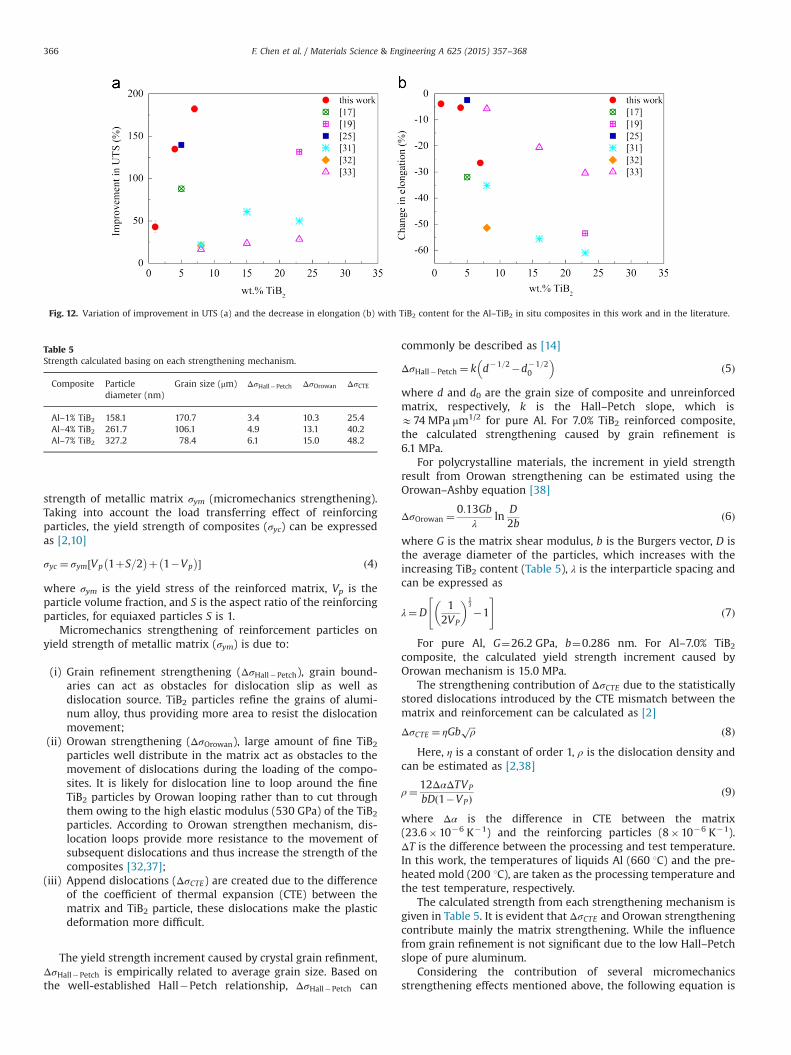
The experimental results in terms of percentage change in UTSand ductility are compared to those reported for TiB2 reinforcedAl-based in situ MMCs available in the literature [17,19,28,34–36].Fig. 12(a) shows that, in spite of lower concentration of reinforce-ment is incorporated, the Al–TiB2 composites in this work show ahigher improvement in strength, indicating that the interfacestirring can offer superior strengthening efficiencies to the final
composites as compared to the conventional process. Fig. 12(b)gives a comparison of the elongation decrease among the Al–TiB2composites. It is found that percentage change in elongation issmaller or comparable in this work with respect to those reportedin the literature. In fact, in present work all the compositessynthesized by the developed interface stirring technique have areal elongation larger than 28.9%, which is much higher than thepreviously reported values.
To investigate the strengthening effects of fine TiB2 particles onthe hardness, tensile properties of the composites, two approacheshave been used to account for the strengthening in the composites[10]. One is based on the load transferring on particle from matrix(the continuum mechanics) which result from the good bondingbetween the soft matrix and defect free TiB2 particles. The other isbased on the strengthening effect of the particles on the yield
Fig. 9. SEM micrographs of the TiB2 morphology in situ Al–7% TiB2 composites: (a) prepared without and (b) with the developed technique.
Fig. 10. SEM micrographs of the composites: (a) Al–1% TiB2; (b) Al–7% TiB2.
Fig. 11. Effect of TiB2 content on the mechanical properties of the fabricatedAl–TiB2 in situ composites.
F. Chen et al. / Materials Science & Engineering A 625 (2015) 357–368 365
strength of metallic matrix σym (micromechanics strengthening).Taking into account the load transferring effect of reinforcingparticles, the yield strength of composites (σyc) can be expressedas [2,10]
σyc ¼ σym½Vp 1þS=2� �þ 1�Vp
� �� ð4Þ
where σym is the yield stress of the reinforced matrix, Vp is theparticle volume fraction, and S is the aspect ratio of the reinforcingparticles, for equiaxed particles S is 1.
Micromechanics strengthening of reinforcement particles onyield strength of metallic matrix (σym) is due to:
(i) Grain refinement strengthening (ΔσHall�Petch), grain bound-aries can act as obstacles for dislocation slip as well asdislocation source. TiB2 particles refine the grains of alumi-num alloy, thus providing more area to resist the dislocationmovement;
(ii) Orowan strengthening (ΔσOrowan), large amount of fine TiB2particles well distribute in the matrix act as obstacles to themovement of dislocations during the loading of the compo-sites. It is likely for dislocation line to loop around the fineTiB2 particles by Orowan looping rather than to cut throughthem owing to the high elastic modulus (530 GPa) of the TiB2
particles. According to Orowan strengthen mechanism, dis-location loops provide more resistance to the movement ofsubsequent dislocations and thus increase the strength of thecomposites [32,37];
(iii) Append dislocations (ΔσCTE) are created due to the differenceof the coefficient of thermal expansion (CTE) between thematrix and TiB2 particle, these dislocations make the plasticdeformation more difficult.
The yield strength increment caused by crystal grain refinment,ΔσHall�Petch is empirically related to average grain size. Based onthe well-established Hall�Petch relationship, ΔσHall�Petch can
commonly be described as [14]
ΔσHall�Petch ¼ k d�1=2�d�1=20
� �ð5Þ
where d and d0 are the grain size of composite and unreinforcedmatrix, respectively, k is the Hall–Petch slope, which isE74 MPa μm1/2 for pure Al. For 7.0% TiB2 reinforced composite,the calculated strengthening caused by grain refinement is6.1 MPa.
For polycrystalline materials, the increment in yield strengthresult from Orowan strengthening can be estimated using theOrowan–Ashby equation [38]
ΔσOrowan ¼0:13Gb
λln
D2b
ð6Þ
where G is the matrix shear modulus, b is the Burgers vector, D isthe average diameter of the particles, which increases with theincreasing TiB2 content (Table 5), λ is the interparticle spacing andcan be expressed as
λ¼D1
2VP
� �13
�1
" #ð7Þ
For pure Al, G¼26.2 GPa, b¼0.286 nm. For Al–7.0% TiB2composite, the calculated yield strength increment caused byOrowan mechanism is 15.0 MPa.
The strengthening contribution of ΔσCTE due to the statisticallystored dislocations introduced by the CTE mismatch between thematrix and reinforcement can be calculated as [2]
ΔσCTE ¼ ηGbffiffiffiρ
p ð8ÞHere, η is a constant of order 1, ρ is the dislocation density and
can be estimated as [2,38]
ρ¼ 12ΔαΔTVP
bD 1�VPð Þ ð9Þ
where Δα is the difference in CTE between the matrix(23.6�10�6 K�1) and the reinforcing particles (8�10�6 K�1).ΔT is the difference between the processing and test temperature.In this work, the temperatures of liquids Al (660 1C) and the pre-heated mold (200 1C), are taken as the processing temperature andthe test temperature, respectively.
The calculated strength from each strengthening mechanism isgiven in Table 5. It is evident that ΔσCTE and Orowan strengtheningcontribute mainly the matrix strengthening. While the influencefrom grain refinement is not significant due to the low Hall–Petchslope of pure aluminum.
Considering the contribution of several micromechanicsstrengthening effects mentioned above, the following equation is
Fig. 12. Variation of improvement in UTS (a) and the decrease in elongation (b) with TiB2 content for the Al–TiB2 in situ composites in this work and in the literature.
Table 5Strength calculated basing on each strengthening mechanism.
Composite Particlediameter (nm)
Grain size (μm) ΔσHall�Petch ΔσOrowan ΔσCTE
Al–1% TiB2 158.1 170.7 3.4 10.3 25.4Al–4% TiB2 261.7 106.1 4.9 13.1 40.2Al–7% TiB2 327.2 78.4 6.1 15.0 48.2
F. Chen et al. / Materials Science & Engineering A 625 (2015) 357–368366
proposed to predict the yield strength of reinforced matrix
σym ¼ σ0þΔσHall�PetchþffiffiffiffiffiffiffiffiffiffiffiffiffiffiffiffiffiffiffiffiffiffiffiffiffiffiffiffiffiffiffiffiffiffiffiffiffiffiffiffiffiffiffiffiffiffiffiΔσOrowanð Þ2þ ΔσCTEð Þ2
qð10Þ
Where σ0 is the yield strength of the unreinforced matrix (sample0). In present study, measured value of σ0 is 24.6 MPa.
After summing the different strengthening results given inTable 5 using Eq. (10), the calculated yield strength of reinforcedmatrix σym is substituted in Eq. (4), then the theoretical yieldstrength values of the developed composites are estimated andplotted in Fig. 9. It is evident that the predicted values estimated byconsidering both the load transfer and the contribution frommatrixstrengthening are comparable to the experimental values. Thepredicted strength value for Al–7% TiB2 is 83.0 MPa, which is veryclose to the experimental value of 85.4 MPa. Concerning thecontribution of different strengthening mechanisms to the obtainedstrength improvements in the final composites, it is obvious thatΔσCTE is the most effective one, followed by the Orowan strength-ening, grain refinement strengthening, and load transferring effect.
3.7. Fractograph
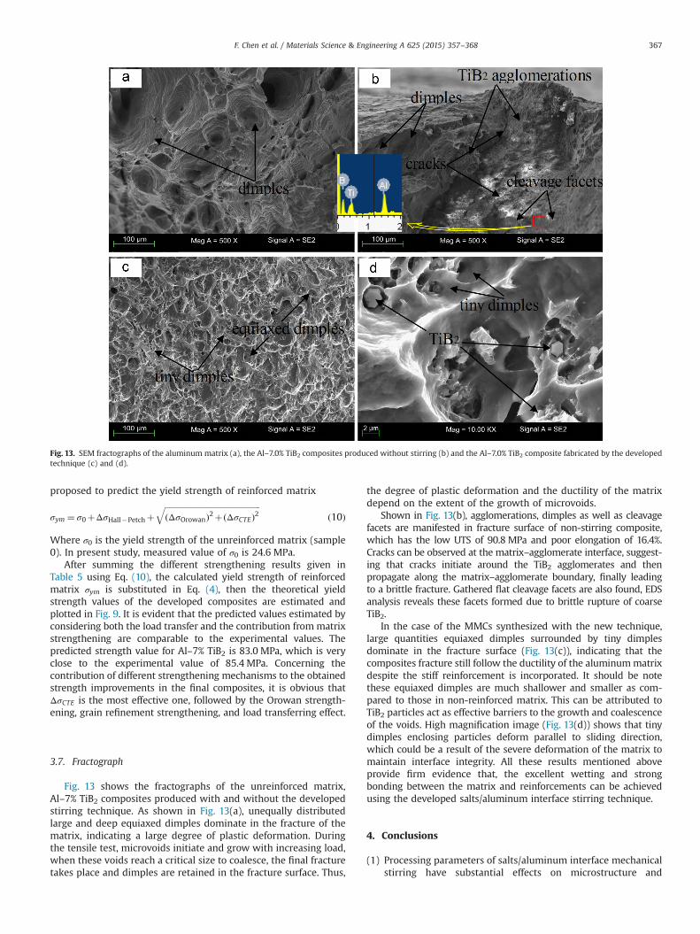
Fig. 13 shows the fractographs of the unreinforced matrix,Al–7% TiB2 composites produced with and without the developedstirring technique. As shown in Fig. 13(a), unequally distributedlarge and deep equiaxed dimples dominate in the fracture of thematrix, indicating a large degree of plastic deformation. Duringthe tensile test, microvoids initiate and grow with increasing load,when these voids reach a critical size to coalesce, the final fracturetakes place and dimples are retained in the fracture surface. Thus,
the degree of plastic deformation and the ductility of the matrixdepend on the extent of the growth of microvoids.
Shown in Fig. 13(b), agglomerations, dimples as well as cleavagefacets are manifested in fracture surface of non-stirring composite,which has the low UTS of 90.8 MPa and poor elongation of 16.4%.Cracks can be observed at the matrix–agglomerate interface, suggest-ing that cracks initiate around the TiB2 agglomerates and thenpropagate along the matrix–agglomerate boundary, finally leadingto a brittle fracture. Gathered flat cleavage facets are also found, EDSanalysis reveals these facets formed due to brittle rupture of coarseTiB2.
In the case of the MMCs synthesized with the new technique,large quantities equiaxed dimples surrounded by tiny dimplesdominate in the fracture surface (Fig. 13(c)), indicating that thecomposites fracture still follow the ductility of the aluminummatrixdespite the stiff reinforcement is incorporated. It should be notethese equiaxed dimples are much shallower and smaller as com-pared to those in non-reinforced matrix. This can be attributed toTiB2 particles act as effective barriers to the growth and coalescenceof the voids. High magnification image (Fig. 13(d)) shows that tinydimples enclosing particles deform parallel to sliding direction,which could be a result of the severe deformation of the matrix tomaintain interface integrity. All these results mentioned aboveprovide firm evidence that, the excellent wetting and strongbonding between the matrix and reinforcements can be achievedusing the developed salts/aluminum interface stirring technique.
4. Conclusions
(1) Processing parameters of salts/aluminum interface mechanicalstirring have substantial effects on microstructure and
Fig. 13. SEM fractographs of the aluminum matrix (a), the Al–7.0% TiB2 composites produced without stirring (b) and the Al–7.0% TiB2 composite fabricated by the developedtechnique (c) and (d).
F. Chen et al. / Materials Science & Engineering A 625 (2015) 357–368 367
mechanical properties of the final composites. Proper stirringintensity and duration are helpful to suppress the formation ofsevere agglomeration, meanwhile, to prevent inclusionentrapping and melt oxidation. TiB2 particle morphology ismainly determined in the first 15 min, while particle distribu-tion affected by the whole holding process.
(2) Interface mechanical stirring significantly improves TiB2 par-ticles distribution in aluminum matrix, defect-free TiB2 rein-forced in situ composites can be produced by applying stirringwith speed of 180 rpm in both the first and the last 15 min ofthe 60 min composite synthesis process.
(3) SR-CT is a powerful tool in the investigation of stereoscopicstructure of in situ TiB2 reinforced Al based composites, amuch better vision of TiB2 distribution has been attained.
(4) The fabricated composites possess much higher improvementsin mechanical properties when compared with the aluminummatrix and the Al–TiB2 in situ composites fabricated byconventional process. The enhancement in the mechanicalproperties mainly result from ΔσCTE , followed by Orowanstrengthening, grain refinement strengthening and load trans-ferring effect.
Acknowledgments
This work was supported by the National Natural ScienceFoundation of China (Nos. 51071035, 51274054, 51375070 andU1332115), and the Key grant Project of Chinese Ministry ofEducation (No. 313011). It is a pleasure to thank Jingyu Han forhis help in the SEM analysis, and Guangyuan Yan for his help inpreparing the SR-CT specimens of the work. The authors also wishto thank the Shanghai Synchrotron Radiation Facility for provisionof synchrotron radiation facilities. Special thanks to all the staffmembers of the BL13W1 beamline of SSRF for their contributionduring the synchrotron experiments.
References
[1] Y. Zhang, N. Ma, H. Wang, Y. Le, X. Li, Mater. Des. 28 (2007) 628–632.[2] S. Jayalakshmi, S. Gupta, S. Sankaranarayanan, S. Sahu, M. Gupta, Mater. Sci.
Eng. A 581 (2013) 119–127.
[3] S.A. Sajjadi, H.R. Ezatpour, M. Torabi Parizi, Mater. Des. 34 (2012) 106–111.[4] P. Poddar, V.C. Srivastava, P.K. De, K.L. Sahoo, Mater. Sci. Eng. A 460–461 (2007)
357–364.[5] S. Gopalakrishnan, N. Murugan, Compos. Part. B-Eng. 43 (2012) 302–308.[6] S. Kumar, M. Chakraborty, V. Subramanya Sarma, B.S. Murty, Wear 265 (2008)
134–142.[7] C.S. Ramesh, A. Ahamed, Wear 271 (2011) 1928–1939.[8] M. Emamy, M. Mahta, J. Rasizadeh, Compos. Sci. Technol. 66 (2006)
1063–1066.[9] S. Lakshmi, L. Lu, M. Gupta, J. Mater. Process. Tech. 73 (1998) 160–166.[10] Q. Zhang, B.L. Xiao, W.G. Wang, Z.Y. Ma, Acta Mater. 60 (2012) 7090–7103.[11] D.G. Zhao, X.F. Liu, Y.C. Pan, X.F. Bian, X.J. Liu, J. Mater. Process. Tech. 189 (2007)
237–241.[12] S. Suresh, N. Shenbag, V. Moorthi, Procedia Eng. 38 (2012) 89–97.[13] Y. Zhang, N. Ma, H. Wang, Mater. Lett. 61 (2007) 3273–3275.[14] T. Wang, Z. Chen, Y. Zheng, Y. Zhao, H. Kang, L. Gao, Mater. Sci. Eng. A 605
(2014) 22–32.[15] A. Mandal, R. Maiti, M. Chakraborty, B.S. Murty, Mater. Sci. Eng. A 386 (2004)
296–300.[16] D. Zhao, X. Liu, Y. Liu, X. Bian, J. Mater. Sci. 40 (2005) 4365–4368.[17] J. Xue, J. Wang, Y. Han, P. Li, B. Sun, J. Alloys Compd. 509 (2011) 1573–1578.[18] F. Wang, J. Xu, J. Li, X. Li, H. Wang, Mater. Des. 33 (2012) 236–241.[19] K.L. Tee, L. Lü, M.O. Lai, Mater. Sci. Eng. A 339 (2003) 227–231.[20] M. Habibnejad-Korayem, R. Mahmudi, W.J. Poole, Mater. Sci. Eng. A 519 (2009)
198–203.[21] S. Amirkhanlou, B. Niroumand, Trans. Nonferr. Met. Soc. China 20 (2010)
s788–s793.[22] F. Xu, Y. Li, X. Hu, Y. Niu, J. Zhao, Z. Zhang, Mater. Lett. 67 (2012) 162–164.[23] M.Y. Wang, Y.J. Xu, T. Jing, G.Y. Peng, Y.N. Fu, N. Chawla, Scr. Mater. 67 (2012)
629–632.[24] R.W. Hamilton, M.F. Forster, R.J. Dashwood, P.D. Lee, Scr. Mater. 46 (2002)
25–29.[25] J. Baruchel, J.Y. Buffiere, P. Cloetens, M. Di Michiel, E. Ferrie, W. Ludwig,
E. Maire, L. Salvo, Scr. Mater. 55 (2006) 41–46.[26] L. Salvo, P. Cloetens, E. Maire, S. Zabler, J.J. Blandin, J.Y. Buffiere, W. Ludwig,
E. Boller, D. Bellet, C. Josserond, Nucl. Instrum. Meth. B 200 (2003) 273–286.[27] Z. Sadeghian, M.H. Enayati, P. Beiss, J. Mater. Sci. 44 (2009) 2566–2572.[28] Z. Chen, T. Wang, Y. Zheng, Y. Zhao, H. Kang, L. Gao, Mater. Sci. Eng. A 605
(2014) 301–309.[29] J. Fjellstedt, A.E.W. Jarfors, Mater. Sci. Eng. A 413 (2005) 527–532.[30] C.F. Feng, L. Froyen, J. Mater. Sci. 35 (2000) 837–850.[31] E.-M. Nahed, M.A. Taha, A.E.W. Jarforsb, H. Fredriksson, J. Alloys Compd. 292
(1999) 221–229.[32] L. Lu, M. LA1, F.L. CHEN, Acta Mater. 45 (1997) 4297–4309.[33] H.B. Michael Rajan, S. Ramabalan, I. Dinaharan, S.J. Vijay, Mater. Des. 44 (2013)
438–445.[34] K.L. Tee, L. Lu, M.O. Lai, J. Mater. Process. Tech. 90 (1999) 513–519.[35] A.R. Kennedy, A.E. Karantzalis, S.M. Wyatt, J. Mater. Sci. 34 (1999) 933–940.[36] S.C. Tjong, K.F. Tam, Mater. Chem. Phys. 97 (2006) 91–97.[37] J. Lee, J.Y. Jung, E.-S. Lee, W.J. Park, S. Ahn, N.J. Kim, Mater. Sci. Eng. A 277
(2000) 274–283.[38] Z. Zhang, D. Chen, Scr. Mater. 54 (2006) 1321–1326.
F. Chen et al. / Materials Science & Engineering A 625 (2015) 357–368368