Embed Size (px)
Citation preview
STN1100
2 of 23 www.obdsol.com STN1100FRPMA
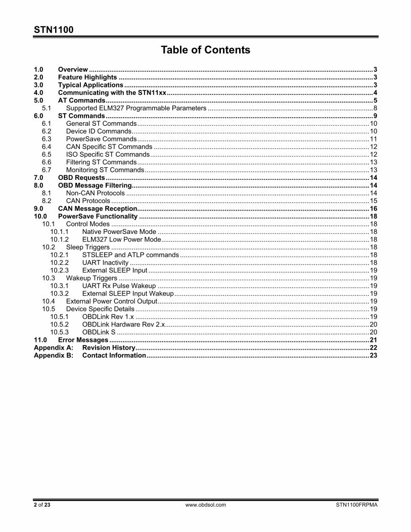
Table of Contents 1.0 Overview ......................................................................................................................................................... 3 2.0 Feature Highlights ......................................................................................................................................... 3 3.0 Typical Applications ...................................................................................................................................... 3 4.0 Communicating with the STN11xx ............................................................................................................... 4 5.0 AT Commands ................................................................................................................................................ 5
5.1 Supported ELM327 Programmable Parameters ......................................................................................... 8 6.0 ST Commands ................................................................................................................................................ 9
6.1 General ST Commands ............................................................................................................................. 10 6.2 Device ID Commands ................................................................................................................................ 10 6.3 PowerSave Commands ............................................................................................................................. 11 6.4 CAN Specific ST Commands .................................................................................................................... 12 6.5 ISO Specific ST Commands ...................................................................................................................... 12 6.6 Filtering ST Commands ............................................................................................................................. 13 6.7 Monitoring ST Commands ......................................................................................................................... 13
7.0 OBD Requests .............................................................................................................................................. 14 8.0 OBD Message Filtering ................................................................................................................................ 14
8.1 Non-CAN Protocols ................................................................................................................................... 14 8.2 CAN Protocols ........................................................................................................................................... 15
9.0 CAN Message Reception............................................................................................................................. 16 10.0 PowerSave Functionality ............................................................................................................................ 18
10.1 Control Modes ........................................................................................................................................... 18 10.1.1 Native PowerSave Mode .................................................................................................................. 18 10.1.2 ELM327 Low Power Mode ................................................................................................................ 18
10.2 Sleep Triggers ........................................................................................................................................... 18 10.2.1 STSLEEP and ATLP commands ...................................................................................................... 18 10.2.2 UART Inactivity ................................................................................................................................. 18 10.2.3 External SLEEP Input ....................................................................................................................... 19
10.3 Wakeup Triggers ....................................................................................................................................... 19 10.3.1 UART Rx Pulse Wakeup .................................................................................................................. 19 10.3.2 External SLEEP Input Wakeup ......................................................................................................... 19
10.4 External Power Control Output .................................................................................................................. 19 10.5 Device Specific Details .............................................................................................................................. 19
10.5.1 OBDLink Rev 1.x .............................................................................................................................. 19 10.5.2 OBDLink Hardware Rev 2.x .............................................................................................................. 20 10.5.3 OBDLink S ........................................................................................................................................ 20
11.0 Error Messages ............................................................................................................................................ 21 Appendix A: Revision History .............................................................................................................................. 22 Appendix B: Contact Information ........................................................................................................................ 23
Family Reference and Programming Manual
STN1100FRPMA www.obdsol.com 3 of 23
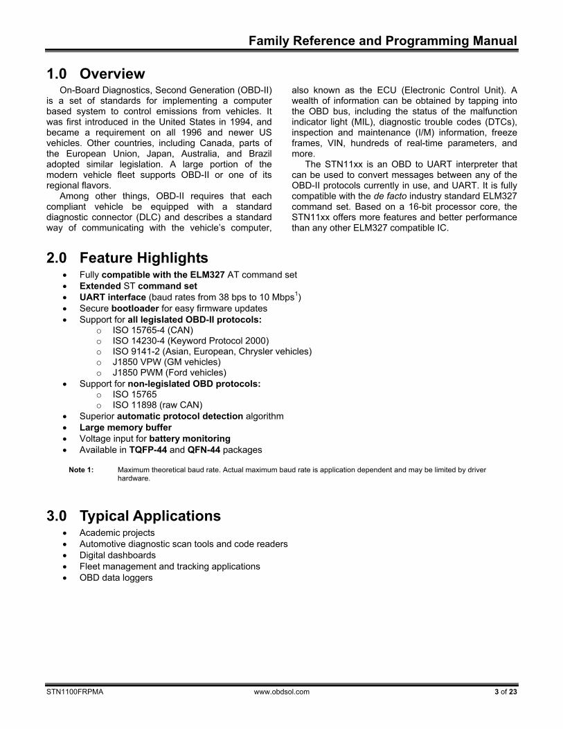
1.0 Overview On-Board Diagnostics, Second Generation (OBD-II)
is a set of standards for implementing a computer based system to control emissions from vehicles. It was first introduced in the United States in 1994, and became a requirement on all 1996 and newer US vehicles. Other countries, including Canada, parts of the European Union, Japan, Australia, and Brazil adopted similar legislation. A large portion of the modern vehicle fleet supports OBD-II or one of its regional flavors.
Among other things, OBD-II requires that each compliant vehicle be equipped with a standard diagnostic connector (DLC) and describes a standard way of communicating with the vehicle’s computer,
also known as the ECU (Electronic Control Unit). A wealth of information can be obtained by tapping into the OBD bus, including the status of the malfunction indicator light (MIL), diagnostic trouble codes (DTCs), inspection and maintenance (I/M) information, freeze frames, VIN, hundreds of real-time parameters, and more.
The STN11xx is an OBD to UART interpreter that can be used to convert messages between any of the OBD-II protocols currently in use, and UART. It is fully compatible with the de facto industry standard ELM327 command set. Based on a 16-bit processor core, the STN11xx offers more features and better performance than any other ELM327 compatible IC.
2.0 Feature Highlights • Fully compatible with the ELM327 AT command set • Extended ST command set • UART interface (baud rates from 38 bps to 10 Mbps1) • Secure bootloader for easy firmware updates • Support for all legislated OBD-II protocols:
o ISO 15765-4 (CAN) o ISO 14230-4 (Keyword Protocol 2000) o ISO 9141-2 (Asian, European, Chrysler vehicles) o J1850 VPW (GM vehicles) o J1850 PWM (Ford vehicles)
• Support for non-legislated OBD protocols: o ISO 15765 o ISO 11898 (raw CAN)
• Superior automatic protocol detection algorithm • Large memory buffer • Voltage input for battery monitoring • Available in TQFP-44 and QFN-44 packages
Note 1: Maximum theoretical baud rate. Actual maximum baud rate is application dependent and may be limited by driver
hardware.
3.0 Typical Applications • Academic projects • Automotive diagnostic scan tools and code readers • Digital dashboards • Fleet management and tracking applications • OBD data loggers
STN1100
4 of 23 www.obdsol.com STN1100FRPMA
4.0 Communicating with the STN11xx The STN11xx uses a three-wire UART connection
that is CMOS/TTL compatible. The UART settings are:
• 38400 baud (default) • 8 data bits • No parity bit • One stop bit • No handshaking
The baud rate is software-selectable (see STBR).
Note: The UART Tx pin is configured as an open drain output and requires a 10 kΩ pull-up resistor. Maximum pull-up voltage is 5 volts.
Once powered and connected, the STN11xx will
display the welcome prompt: ELM327 v1.3a > The STN11xx sends the ‘>’ (“prompt”) character, to
signal that it is ready for more input. User software should always wait for the prompt before sending the next command.
There are three types of commands recognized by the STN11xx: AT commands, ST commands, and OBD requests.
The STN11xx is designed to fully emulate the ELM327 AT command set supported by many existing OBD software applications. AT commands begin with “AT” and are intended for the IC. They cause the STN11xx to carry out some action – change or display settings, perform a reset, and so on. A list of supported AT commands can be found in section 5.0.
In order to provide additional functionality while maintaining compatibility with the ELM327 command set, the STN11xx supports a parallel ST command set, described in section 6.0.
OBD requests are messages that are transmitted
on the OBD bus. Only ASCII hexadecimal digits (0-9 and A-F) are allowed in OBD requests.
Only ASCII alpha characters, numbers, backspaces, and the carriage return are accepted on the UART, spaces are ignored. All commands must terminate with a carriage return (0x0D).
By default, responses from the STN11xx are terminated with a carriage return (0x0D). ATL1 command can be used to have the STN11xx append line feeds (0x0A) to the carriage returns.
Sending a single carriage return character repeats the last command.
Family Reference and Programming Manual
STN1100FRPMA www.obdsol.com 5 of 23
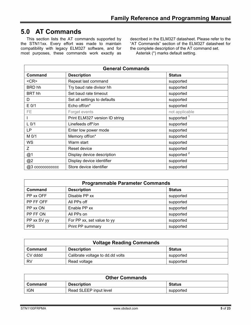
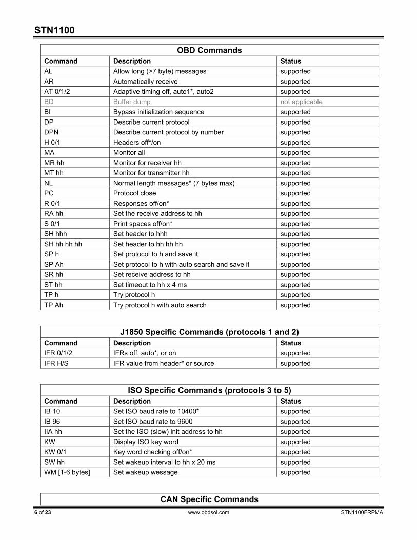
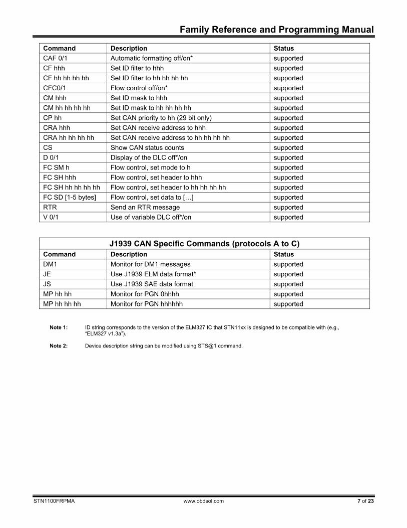
5.0 AT Commands This section lists the AT commands supported by
the STN11xx. Every effort was made to maintain compatibility with legacy ELM327 software, and for most purposes, these commands work exactly as
described in the ELM327 datasheet. Please refer to the “AT Commands” section of the ELM327 datasheet for the complete description of the AT command set.
Asterisk (*) marks default setting.
General Commands Command Description Status <CR> Repeat last command supported BRD hh Try baud rate divisor hh supported BRT hh Set baud rate timeout supported D Set all settings to defaults supported E 0/1 Echo off/on* supported FE Forget events not applicable I Print ELM327 version ID string supported 1 L 0/1 Linefeeds off*/on supported LP Enter low power mode supported M 0/1 Memory off/on* supported WS Warm start supported Z Reset device supported @1 Display device description supported 2 @2 Display device identifier supported @3 cccccccccccc Store device identifier supported
Programmable Parameter Commands Command Description Status PP xx OFF Disable PP xx supported PP FF OFF All PPs off supported PP xx ON Enable PP xx supported PP FF ON All PPs on supported PP xx SV yy For PP xx, set value to yy supported PPS Print PP summary supported
Voltage Reading Commands Command Description Status CV dddd Calibrate voltage to dd.dd volts supported RV Read voltage supported
Other Commands Command Description Status IGN Read SLEEP input level supported
STN1100
6 of 23 www.obdsol.com STN1100FRPMA
OBD CommandsCommand Description Status AL Allow long (>7 byte) messages supported AR Automatically receive supported AT 0/1/2 Adaptive timing off, auto1*, auto2 supported BD Buffer dump not applicable BI Bypass initialization sequence supported DP Describe current protocol supported DPN Describe current protocol by number supported H 0/1 Headers off*/on supported MA Monitor all supported MR hh Monitor for receiver hh supported MT hh Monitor for transmitter hh supported NL Normal length messages* (7 bytes max) supported PC Protocol close supported R 0/1 Responses off/on* supported RA hh Set the receive address to hh supported S 0/1 Print spaces off/on* supported SH hhh Set header to hhh supported SH hh hh hh Set header to hh hh hh supported SP h Set protocol to h and save it supported SP Ah Set protocol to h with auto search and save it supported SR hh Set receive address to hh supported ST hh Set timeout to hh x 4 ms supported TP h Try protocol h supported TP Ah Try protocol h with auto search supported
J1850 Specific Commands (protocols 1 and 2) Command Description Status IFR 0/1/2 IFRs off, auto*, or on supported IFR H/S IFR value from header* or source supported
ISO Specific Commands (protocols 3 to 5) Command Description Status IB 10 Set ISO baud rate to 10400* supported IB 96 Set ISO baud rate to 9600 supported IIA hh Set the ISO (slow) init address to hh supported KW Display ISO key word supported KW 0/1 Key word checking off/on* supported SW hh Set wakeup interval to hh x 20 ms supported WM [1-6 bytes] Set wakeup wessage supported
CAN Specific Commands
Family Reference and Programming Manual
STN1100FRPMA www.obdsol.com 7 of 23
Command Description Status CAF 0/1 Automatic formatting off/on* supported CF hhh Set ID filter to hhh supported CF hh hh hh hh Set ID filter to hh hh hh hh supported CFC0/1 Flow control off/on* supported CM hhh Set ID mask to hhh supported CM hh hh hh hh Set ID mask to hh hh hh hh supported CP hh Set CAN priority to hh (29 bit only) supported CRA hhh Set CAN receive address to hhh supported CRA hh hh hh hh Set CAN receive address to hh hh hh hh supported CS Show CAN status counts supported D 0/1 Display of the DLC off*/on supported FC SM h Flow control, set mode to h supported FC SH hhh Flow control, set header to hhh supported FC SH hh hh hh hh Flow control, set header to hh hh hh hh supported FC SD [1-5 bytes] Flow control, set data to […] supported RTR Send an RTR message supported V 0/1 Use of variable DLC off*/on supported
J1939 CAN Specific Commands (protocols A to C) Command Description Status DM1 Monitor for DM1 messages supported JE Use J1939 ELM data format* supported JS Use J1939 SAE data format supported MP hh hh Monitor for PGN 0hhhh supported MP hh hh hh Monitor for PGN hhhhhh supported
Note 1: ID string corresponds to the version of the ELM327 IC that STN11xx is designed to be compatible with (e.g., “ELM327 v1.3a”).
Note 2: Device description string can be modified using STS@1 command.
STN1100
8 of 23 www.obdsol.com STN1100FRPMA
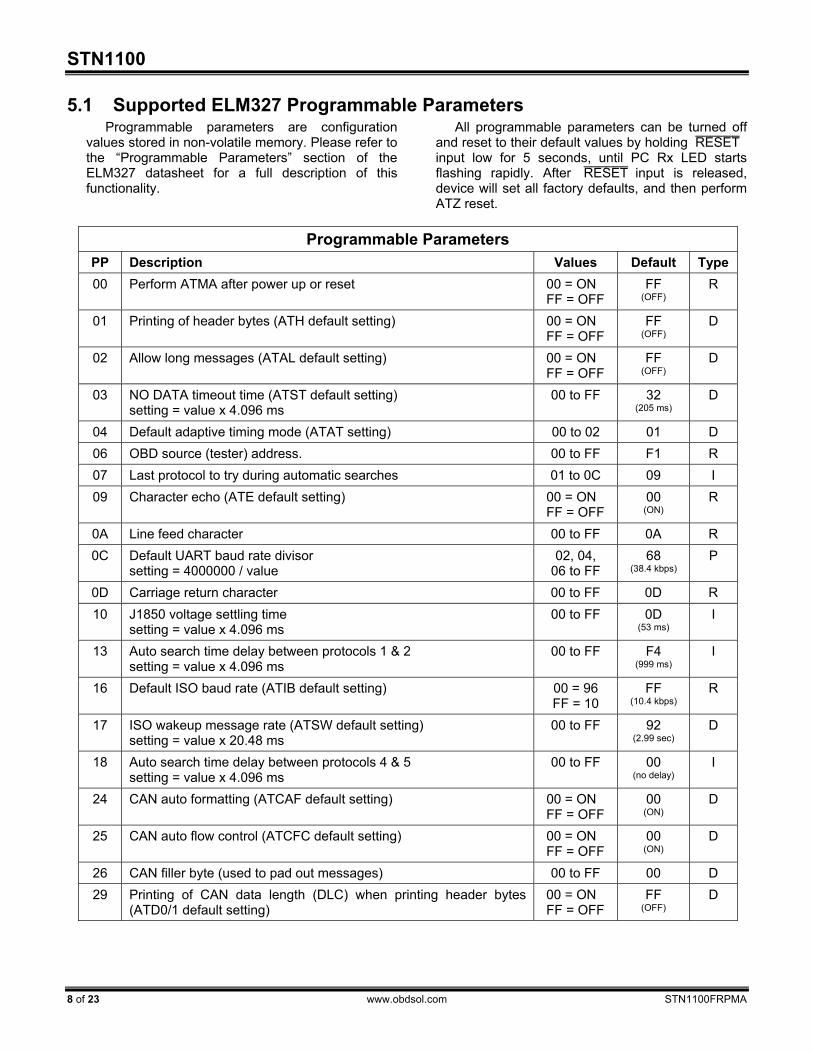
5.1 Supported ELM327 Programmable Parameters Programmable parameters are configuration
values stored in non-volatile memory. Please refer to the “Programmable Parameters” section of the ELM327 datasheet for a full description of this functionality.
All programmable parameters can be turned off and reset to their default values by holding RESET ¯¯¯¯¯¯ input low for 5 seconds, until PC Rx LED starts flashing rapidly. After RESET ¯¯¯¯¯¯ input is released, device will set all factory defaults, and then perform ATZ reset.
Programmable Parameters
PP Description Values Default Type 00 Perform ATMA after power up or reset 00 = ON
FF = OFF FF
(OFF) R
01 Printing of header bytes (ATH default setting) 00 = ON FF = OFF
FF (OFF)
D
02 Allow long messages (ATAL default setting) 00 = ON FF = OFF
FF (OFF)
D
03 NO DATA timeout time (ATST default setting) setting = value x 4.096 ms
00 to FF 32 (205 ms)
D
04 Default adaptive timing mode (ATAT setting) 00 to 02 01 D 06 OBD source (tester) address. 00 to FF F1 R 07 Last protocol to try during automatic searches 01 to 0C 09 I 09 Character echo (ATE default setting) 00 = ON
FF = OFF 00
(ON) R
0A Line feed character 00 to FF 0A R 0C Default UART baud rate divisor
setting = 4000000 / value 02, 04,
06 to FF 68
(38.4 kbps) P
0D Carriage return character 00 to FF 0D R 10 J1850 voltage settling time
setting = value x 4.096 ms 00 to FF 0D
(53 ms) I
13 Auto search time delay between protocols 1 & 2 setting = value x 4.096 ms
00 to FF F4 (999 ms)
I
16 Default ISO baud rate (ATIB default setting) 00 = 96 FF = 10
FF (10.4 kbps)
R
17 ISO wakeup message rate (ATSW default setting) setting = value x 20.48 ms
00 to FF 92 (2.99 sec)
D
18 Auto search time delay between protocols 4 & 5 setting = value x 4.096 ms
00 to FF 00 (no delay)
I
24 CAN auto formatting (ATCAF default setting) 00 = ON FF = OFF
00 (ON)
D
25 CAN auto flow control (ATCFC default setting) 00 = ON FF = OFF
00 (ON)
D
26 CAN filler byte (used to pad out messages) 00 to FF 00 D 29 Printing of CAN data length (DLC) when printing header bytes
(ATD0/1 default setting) 00 = ON FF = OFF
FF (OFF)
D

Family Reference and Programming Manual
STN1100FRPMA www.obdsol.com 9 of 23
6.0 ST Commands ST commands are designed to provide extended
functionality, without breaking compatibility with the ELM327 AT command set. Both command sets are available simultaneously.
General
Command Description BR baud Switch UART baud rate in software-friendly way BRT ms Set UART baud rate switch timeout S@1 ascii Set AT@1 device description string SATI ascii Set ATI device ID string SBR baud Switch UART baud rate in terminal-friendly way WBR Write current UART baud rate to NVM
Device ID Command Description DI Print device hardware ID string (e.g., “OBDLink r1.7”) I Print firmware ID string (e.g., “STN1100 v1.2.3”) MFR Print device manufacturer ID string SN Print device serial number
PowerSave Command Description SLCS Print active PowerSave configuration summary SLEEP [delay] Enter sleep mode with optional delay SLLT Report last sleep/wakeup triggers SLPCP 0/1 Set PWR_CTRL output polarity SLU sleep, wakeup UART sleep/wakeup triggers on/off SLUIT sec Set UART inactivity timeout SLUWP min, max Set UART wakeup pulse timing SLX sleep, wakeup External sleep trigger on/off SLXP 0/1 Set polarity of the external sleep control input SLXS Print external SLEEP input status SLXST ms Set minimum active time for external sleep trigger before entering sleep SLXWT ms Set minimum inactive time for external sleep trigger before wakeup
ISO Specific Command Description IAT 0/1 Turn adaptive maximum interbyte timing (P1 max) off/on* IBR baud Set ISO baud rate IMCS 0/1 Turn ISO manual checksum off*/on IP1X ms Set maximum interbyte time for receiving messages (P1 max) IP4 ms Set interbyte time for transmitting messages (P4)
STN1100
10 of 23 www.obdsol.com STN1100FRPMA
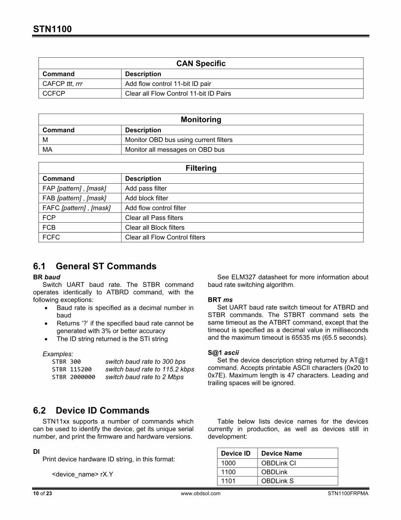
CAN Specific Command Description CAFCP ttt, rrr Add flow control 11-bit ID pair CCFCP Clear all Flow Control 11-bit ID Pairs
Monitoring Command Description M Monitor OBD bus using current filters MA Monitor all messages on OBD bus
Filtering
Command Description FAP [pattern] , [mask] Add pass filter FAB [pattern] , [mask] Add block filter FAFC [pattern] , [mask] Add flow control filter FCP Clear all Pass filters FCB Clear all Block filters FCFC Clear all Flow Control filters
6.1 General ST Commands BR baud
Switch UART baud rate. The STBR command operates identically to ATBRD command, with the following exceptions:
• Baud rate is specified as a decimal number in baud
• Returns ‘?’ if the specified baud rate cannot be generated with 3% or better accuracy
• The ID string returned is the STI string Examples:
STBR 300 switch baud rate to 300 bps STBR 115200 switch baud rate to 115.2 kbps STBR 2000000 switch baud rate to 2 Mbps
See ELM327 datasheet for more information about baud rate switching algorithm. BRT ms
Set UART baud rate switch timeout for ATBRD and STBR commands. The STBRT command sets the same timeout as the ATBRT command, except that the timeout is specified as a decimal value in milliseconds and the maximum timeout is 65535 ms (65.5 seconds). S@1 ascii
Set the device description string returned by AT@1 command. Accepts printable ASCII characters (0x20 to 0x7E). Maximum length is 47 characters. Leading and trailing spaces will be ignored.
6.2 Device ID Commands
STN11xx supports a number of commands which can be used to identify the device, get its unique serial number, and print the firmware and hardware versions. DI
Print device hardware ID string, in this format:
<device_name> rX.Y
Table below lists device names for the devices currently in production, as well as devices still in development:
Device ID Device Name 1000 OBDLink CI 1100 OBDLink 1101 OBDLink S
Family Reference and Programming Manual
STN1100FRPMA www.obdsol.com 11 of 23
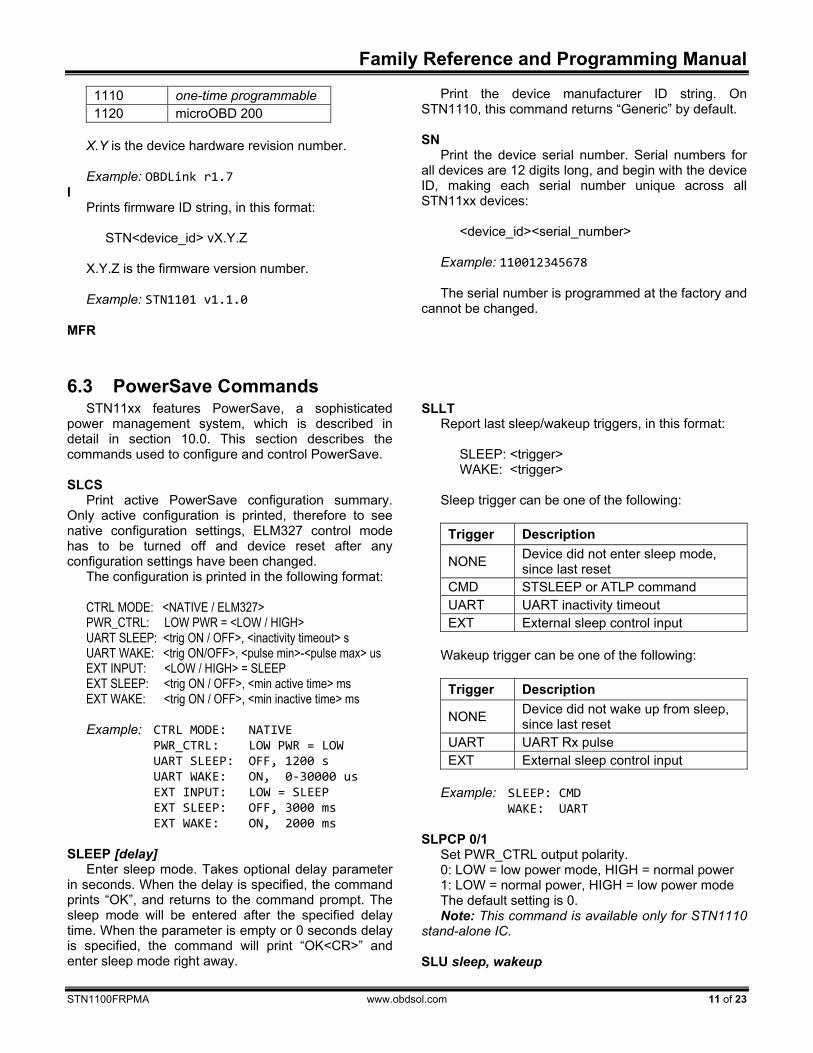
1110 one-time programmable 1120 microOBD 200
X.Y is the device hardware revision number. Example: OBDLink r1.7
I Prints firmware ID string, in this format:
STN<device_id> vX.Y.Z X.Y.Z is the firmware version number. Example: STN1101 v1.1.0
MFR
Print the device manufacturer ID string. On STN1110, this command returns “Generic” by default. SN
Print the device serial number. Serial numbers for all devices are 12 digits long, and begin with the device ID, making each serial number unique across all STN11xx devices:
<device_id><serial_number>
Example: 110012345678
The serial number is programmed at the factory and
cannot be changed.
6.3 PowerSave Commands
STN11xx features PowerSave, a sophisticated power management system, which is described in detail in section 10.0. This section describes the commands used to configure and control PowerSave. SLCS
Print active PowerSave configuration summary. Only active configuration is printed, therefore to see native configuration settings, ELM327 control mode has to be turned off and device reset after any configuration settings have been changed.
The configuration is printed in the following format: CTRL MODE: <NATIVE / ELM327> PWR_CTRL: LOW PWR = <LOW / HIGH> UART SLEEP: <trig ON / OFF>, <inactivity timeout> s UART WAKE: <trig ON/OFF>, <pulse min>-<pulse max> us EXT INPUT: <LOW / HIGH> = SLEEP EXT SLEEP: <trig ON / OFF>, <min active time> ms EXT WAKE: <trig ON / OFF>, <min inactive time> ms Example: CTRL MODE: NATIVE PWR_CTRL: LOW PWR = LOW UART SLEEP: OFF, 1200 s UART WAKE: ON, 0‐30000 us EXT INPUT: LOW = SLEEP EXT SLEEP: OFF, 3000 ms EXT WAKE: ON, 2000 ms
SLEEP [delay]
Enter sleep mode. Takes optional delay parameter in seconds. When the delay is specified, the command prints “OK”, and returns to the command prompt. The sleep mode will be entered after the specified delay time. When the parameter is empty or 0 seconds delay is specified, the command will print “OK<CR>” and enter sleep mode right away.
SLLT Report last sleep/wakeup triggers, in this format:
SLEEP: <trigger> WAKE: <trigger>
Sleep trigger can be one of the following:
Trigger Description
NONE Device did not enter sleep mode, since last reset
CMD STSLEEP or ATLP command UART UART inactivity timeout EXT External sleep control input
Wakeup trigger can be one of the following:
Trigger Description
NONE Device did not wake up from sleep, since last reset
UART UART Rx pulse EXT External sleep control input
Example: SLEEP: CMD WAKE: UART
SLPCP 0/1
Set PWR_CTRL output polarity. 0: LOW = low power mode, HIGH = normal power 1: LOW = normal power, HIGH = low power mode The default setting is 0. Note: This command is available only for STN1110
stand-alone IC. SLU sleep, wakeup

STN1100
12 of 23 www.obdsol.com STN1100FRPMA
UART sleep/wakeup triggers on/off. Each of the two parameters can be specified as “on” or “off”. The first parameter specifies sleep trigger (UART inactivity timeout) setting, second – wakeup trigger (low pulse on UART Rx input) setting. The defaults are sleep = off, wake = on. SLUIT sec
Set UART inactivity timeout. The parameter is specified in seconds (decimal). The default is 1200 (20 minutes). SLUWP min, max
Set UART wakeup pulse timing. The parameters are specified in microseconds. The defaults are min = 0, max = 30000 (30 ms). SLX sleep, wakeup
External sleep trigger on/off. Enables/disables sleep/wakeup triggers for the external sleep control input (SLEEP). Each of the two parameters can be specified as “on” or “off”. The first parameter specifies the sleep trigger (SLEEP input low) setting, and the second specifies the wakeup trigger (SLEEP input high) setting. The defaults are sleep = off, wake = on.
SLXP 0/1 Set polarity of the external sleep control input. 0: LOW = enter sleep, HIGH = wake up 1: LOW = wake up, HIGH = enter sleep The default setting is 0. Note: This command is available only for STN1110
stand-alone IC and microOBD 200 (STN1120). SLXS
Print external SLEEP input status. Responds with “WAKE” or “SLEEP”. SLXST ms
Set minimum active time for external sleep trigger before entering sleep. Sets the length of time in milliseconds the external sleep control input must remain in the active (logic low) state, before the device enters sleep mode. The default is 3000 (3 seconds). SLXWT ms
Set minimum inactive time for external sleep trigger before wakeup. Sets the length of time in milliseconds the external sleep control input must be held in the inactive (logic high) state before the device wakes from the sleep mode. The default is 2000 (2 seconds).
6.4 CAN Specific ST Commands CAFCP ttt, rrr
Add a flow control 11-bit CAN ID pair. Takes two three-digit parameters: ttt is transmitter ID, and rrr is receiver ID. For example, STCAFCP 7E0,7E8.
CCFCP Clear all flow control 11-bit ID pairs.
6.5 ISO Specific ST Commands IAT 0/1
Turn ISO adaptive P1 max timing off/on*. When this mode is on, maximum interbyte time (P1 max) for ISO 9141 messages is adaptively reduced to allow communication with some ECUs that do not comply with the minimum intermessage time (P2 min) specified in ISO 9141-2 standard. It is on by default. IBR baud
Set ISO baud rate. Takes a decimal parameter, expressed in bits per second (bps). Supported baud rates are 612 to 65535 bps (65.5 kbps). IMCS 0/1
Turn ISO manual checksum off*/on. When this setting is on, STN11xx will not automatically append checksum byte for transmitted messages, or verify checksum for received messages. Additionally, for KWP2000 protocols (4 and 5), minimum allowed OBD
request length is increased to 2 bytes (one data byte and checksum). IP1X ms
Set maximum interbyte time for receiving ISO messages (P1 max). Takes a decimal parameter in milliseconds. Default is 20 ms. IP4 ms
Set interbyte time for transmitting ISO messages (P4). Takes a decimal parameter in milliseconds. Default is 5 ms.

Family Reference and Programming Manual
STN1100FRPMA www.obdsol.com 13 of 23
6.6 Filtering ST Commands Each of the Add Filter commands dynamically
allocates a block of RAM to store the filter, and can return OUT OF MEMORY error if there is not enough memory to add the filter. If this occurs, OBD requests may start generating the OUT OF MEMORY errors because the OBD memory buffer is located in the same RAM. FAP [pattern], [mask]
Add a pass filter. Takes two parameters: pattern and mask. Pattern and mask can be any length from 0 to 5 bytes (0 to 10 ASCII characters), but both have to be the same length. The messages are matched MSB first, up to the filter length. Messages shorter than the filter length, will not match that filter.
If an odd number of ASCII characters is specified, a leading 0 will be added to the first byte. In other words,
STFAP 7E8,7FF ..is the same as STFAP 07E8,07FF
For 29-bit CAN, the first four bytes are CAN ID; for 11-bit CAN, the first two bytes are CAN ID.
The first 3 bits for 29-bit CAN or the first 5 bits for 11-bit CAN should be don't care (0s in mask) and/or 0s in pattern. FAB [pattern], [mask]
Add block filter. Same syntax as STFAP. FAFC [pattern], [mask]
Add flow control filter. Same syntax as STFAP. FCP
Clear all pass filters. FCB
Clear all block filters. FCFC
Clear all flow control filters.
6.7 Monitoring ST Commands M
Monitor OBD bus using current filters. MA
Monitor all messages on OBD bus. For CAN protocols, all messages will be treated as ISO 15765. To monitor raw CAN messages, use STM command.
STN1100
14 of 23 www.obdsol.com STN1100FRPMA
7.0 OBD Requests The STN11xx uses the same format for OBD
requests as the ELM327. Please refer to the “OBD Commands” section of the ELM327 datasheet for information.
See the following standards for more information about legislated On-Board Diagnostics:
SAE J1979: E/E Diagnostic Test Modes. This document describes data reporting requirements of On-Board Diagnostic regulations in the United States and Europe, and any other region that may adopt similar requirements in the future. The ISO equivalent of this standard is ISO 15031-5.
SAE J2190: Enhanced E/E Diagnostic Test Modes. This document describes the implementation
of Enhanced Diagnostic Test Modes, which are intended to supplement the legislated Diagnostic Test Modes defined in SAE J1979 standard. Modes are defined for access to emission related test data beyond what is included in SAE J1979, and for non-emission related data.
SAE J2178: Class B Data Communication Network Messages. This document describes the information contained in the header and data fields of non-diagnostic messages for automotive serial communications based on SAE J1850 Class B networks.
8.0 OBD Message Filtering
STN11xx supports pass, block, and flow control filters. Their operation is backwards compatible with the ELM327, however STN11xx filtering scheme is much more powerful and flexible. It allows the user to set up multiple filters and fine tune them to receive only those messages that are of interest to the user.
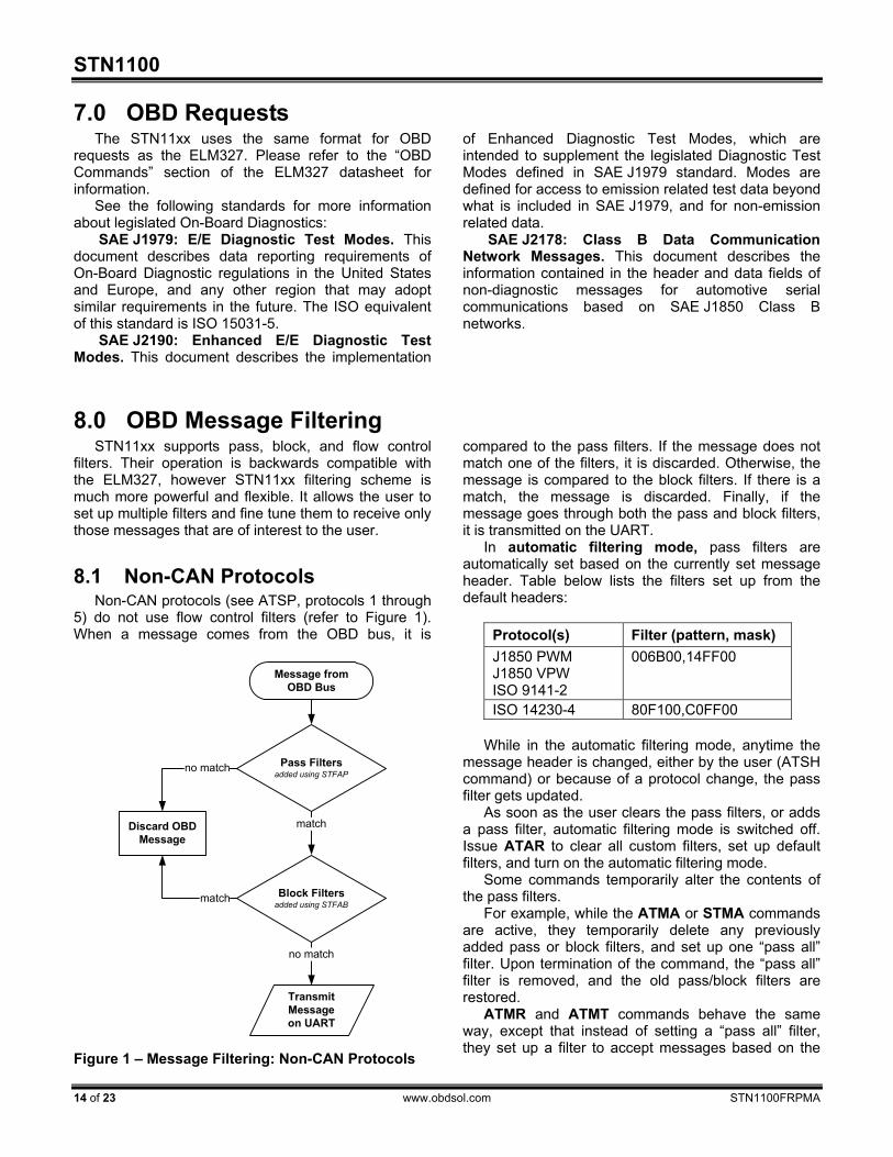
8.1 Non-CAN Protocols Non-CAN protocols (see ATSP, protocols 1 through
5) do not use flow control filters (refer to Figure 1). When a message comes from the OBD bus, it is
compared to the pass filters. If the message does not match one of the filters, it is discarded. Otherwise, the message is compared to the block filters. If there is a match, the message is discarded. Finally, if the message goes through both the pass and block filters, it is transmitted on the UART.
In automatic filtering mode, pass filters are automatically set based on the currently set message header. Table below lists the filters set up from the default headers:
Protocol(s) Filter (pattern, mask) J1850 PWM J1850 VPW ISO 9141-2
006B00,14FF00
ISO 14230-4 80F100,C0FF00 While in the automatic filtering mode, anytime the
message header is changed, either by the user (ATSH command) or because of a protocol change, the pass filter gets updated.
As soon as the user clears the pass filters, or adds a pass filter, automatic filtering mode is switched off. Issue ATAR to clear all custom filters, set up default filters, and turn on the automatic filtering mode.
Some commands temporarily alter the contents of the pass filters.
For example, while the ATMA or STMA commands are active, they temporarily delete any previously added pass or block filters, and set up one “pass all” filter. Upon termination of the command, the “pass all” filter is removed, and the old pass/block filters are restored.
ATMR and ATMT commands behave the same way, except that instead of setting a “pass all” filter, they set up a filter to accept messages based on the
Message fromOBD Bus
Pass Filtersadded using STFAP
Discard OBD Message
Block Filtersadded using STFAB
Transmit Message on UART
no match
no match
match
match
Figure 1 – Message Filtering: Non-CAN Protocols
Family Reference and Programming Manual
STN1100FRPMA www.obdsol.com 15 of 23
address of the receive (or transmit) node passed as the parameter.
STM command uses all filters “as-set”: it does not modify them in any way.
ATSR turns off the automatic filtering mode, and sets up a pass filter to accept messages sent to the receive address provided as the parameter to ATSR.
In order to directly manipulate the filters, use the filtering ST commands described in section 6.6.
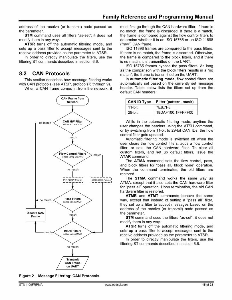
8.2 CAN Protocols This section describes how message filtering works
with CAN protocols (see ATSP, protocols 6 through 9). When a CAN frame comes in from the network, it
must first go through the CAN hardware filter. If there is no match, the frame is discarded. If there is a match, the frame is compared against the flow control filters to determine whether it is an ISO 15765 or an ISO 11898 (“raw”) CAN frame.
ISO 11898 frames are compared to the pass filters. If there is no match, the frame is discarded. Otherwise, the frame is compared to the block filters, and if there is no match, it is transmitted on the UART.
ISO 15765 frames bypass the pass filters. As long as the comparison with the block filters results in a “no match”, the frame is transmitted on the UART.
In automatic filtering mode, flow control filters are automatically set based on the currently set message header. Table below lists the filters set up from the default CAN headers:
CAN ID Type Filter (pattern, mask) 11-bit 7E8,7F8 29-bit 18DAF100,1FFFFF00
While in the automatic filtering mode, anytime the
user changes the headers using the ATSH command, or by switching from 11-bit to 29-bit CAN IDs, the flow control filter gets updated.
Automatic filtering mode is switched off when the user clears the flow control filters, adds a flow control filter, or sets the CAN hardware filter. To clear all custom filters, and set up default filters, issue the ATAR command.
The ATMA command sets the flow control, pass, and block filters for “pass all, block none” operation. When the command terminates, the old filters are restored.
The STMA command works the same way as ATMA, except that it also sets the CAN hardware filter for “pass all” operation. Upon termination, the old CAN hardware filter is restored.
ATMR and ATMT commands behave the same way, except that instead of setting a “pass all” filter, they set up a filter to accept messages based on the address of the receive (or transmit) node passed as the parameter.
STM command uses the filters “as-set”: it does not modify them in any way.
ATSR turns off the automatic filtering mode, and sets up a pass filter to accept messages sent to the receive address provided as the parameter to ATSR.
In order to directly manipulate the filters, use the filtering ST commands described in section 6.6.
CAN Frame from Network
Flow Control Filters added using STFAFC
Pass Filtersadded using STFAP
Discard CAN Frame
Block Filtersadded using STFAB
Transmit CAN Frame
on UART
CAN HW Filterset via ATCF/ATCM
no match
match
match
ISO15765 Frame
no match
no match
no match
match
match
ISO11898 Frame
Figure 2 – Message Filtering: CAN Protocols
STN1100
16 of 23 www.obdsol.com STN1100FRPMA
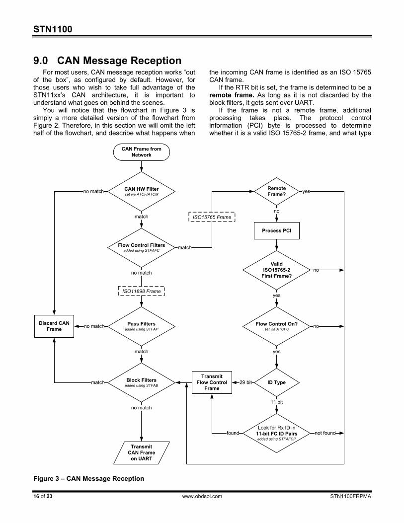
9.0 CAN Message Reception For most users, CAN message reception works “out
of the box”, as configured by default. However, for those users who wish to take full advantage of the STN11xx’s CAN architecture, it is important to understand what goes on behind the scenes.
You will notice that the flowchart in Figure 3 is simply a more detailed version of the flowchart from Figure 2. Therefore, in this section we will omit the left half of the flowchart, and describe what happens when
the incoming CAN frame is identified as an ISO 15765 CAN frame.
If the RTR bit is set, the frame is determined to be a remote frame. As long as it is not discarded by the block filters, it gets sent over UART.
If the frame is not a remote frame, additional processing takes place. The protocol control information (PCI) byte is processed to determine whether it is a valid ISO 15765-2 frame, and what type
Figure 3 – CAN Message Reception
CAN Frame from Network
Flow Control Filters added using STFAFC
Process PCI
Pass Filtersadded using STFAP
Flow Control On?set via ATCFC
ID Type
Look for Rx ID in11-bit FC ID Pairsadded using STFAFCP
TransmitFlow Control
Frame
Discard CAN Frame
Block Filtersadded using STFAB
Transmit CAN Frame
on UART
CAN HW Filterset via ATCF/ATCM
no match
match
match
ISO15765 Frame
Remote Frame?
no
yes
ValidISO15765-2
First Frame?
yes
no
yes
no
11 bit
29 bit
no match
no match
no match
not found
match
match
found
ISO11898 Frame
Family Reference and Programming Manual
STN1100FRPMA www.obdsol.com 17 of 23
of frame it is (single, first, consecutive, or flow control). If the frame is not a valid ISO 15765-2 first frame, or
if flow control is off, it is passed to the block filters. If the frame is a valid ISO 15765-2 first frame, and
flow control is on, what happens next is determined by the ID type.
A 29-bit frame ID contains the address of the transmitter, therefore a flow control frame is transmitted for every ISO 15765-2 first frame, before the frame is passed to the block filters.
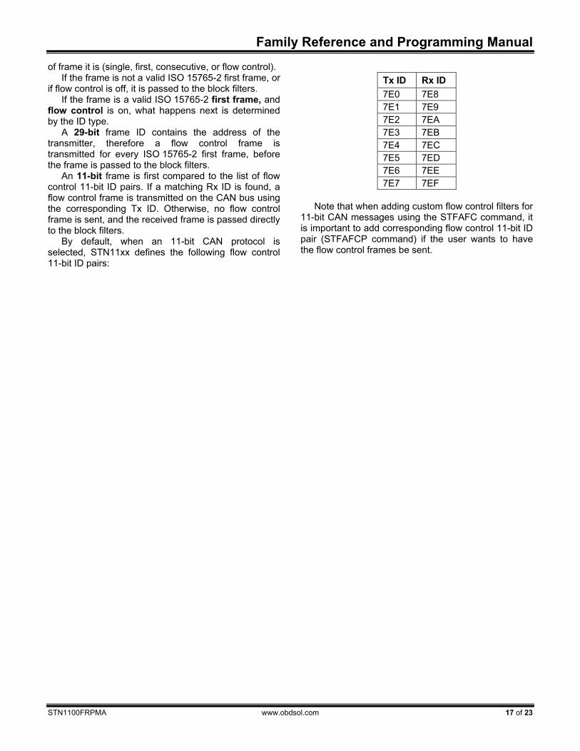
An 11-bit frame is first compared to the list of flow control 11-bit ID pairs. If a matching Rx ID is found, a flow control frame is transmitted on the CAN bus using the corresponding Tx ID. Otherwise, no flow control frame is sent, and the received frame is passed directly to the block filters.
By default, when an 11-bit CAN protocol is selected, STN11xx defines the following flow control 11-bit ID pairs:
Tx ID Rx ID 7E0 7E8 7E1 7E9 7E2 7EA 7E3 7EB 7E4 7EC 7E5 7ED 7E6 7EE 7E7 7EF
Note that when adding custom flow control filters for
11-bit CAN messages using the STFAFC command, it is important to add corresponding flow control 11-bit ID pair (STFAFCP command) if the user wants to have the flow control frames be sent.
STN1100
18 of 23 www.obdsol.com STN1100FRPMA
10.0 PowerSave Functionality STN11xx features a sophisticated power manage-
ment system (PowerSave™) that can be used to put the device in low power mode. The primary purpose of PowerSave is to prevent the vehicle’s battery from being drained when the device is left plugged in for extended periods of time (e.g., permanent in-vehicle installations).
Several sleep and wakeup triggers are available. Each trigger can be independently enabled or disabled.
The following sections describe the PowerSave functionality, while section 6.3 describes the commands and parameters used to configure and control the power management system. You can use the STSLCS command to print a summary of the the active PowerSave configuration settings.
10.1 Control Modes There are two control modes for the PowerSave
functionality: native and ELM327. Use bit 7 (“master enable”) of the programmable parameter 0E (PP 0E) to switch between the modes. See the description of the AT PP command for more information about PP 0E.
By default, STN11xx is in the native PowerSave control mode.
10.1.1 Native PowerSave Mode When the “master enable” bit of PP 0E is cleared,
or PP 0E is off, STN11xx is in the native PowerSave control mode.
In this mode, the rest of the 0E programmable parameter bits are ignored and the PowerSave is controlled exclusively via STSL commands. In native mode, the ATLP command is unavailable. Also, the ELM327 “ACT ALERT” and “LP ALERT” messages are not displayed.
10.1.2 ELM327 Low Power Mode Note: this mode had been implemented for
compatibility with software written for the ELM327. The native PowerSave mode has a number of important advantages over the ELM327 Low Power mode, including higher flexibility, more straightforward configuration, and default settings that had been optimized for more reliable performance.
When the “master enable” bit of the 0E programmable parameter is set and PP 0E is on, STN11xx is in the ELM327 control mode.
In this mode, most PowerSave settings are overridden by the PP 0E. However, settings that do not have their equivalent in the PP 0E can still be adjusted via their corresponding STSL commands. These settings are the UART wakeup pulse timing and external SLEEP control polarity.
By default, instead of the fixed ELM327 minimum UART Rx wakeup pulse requirement of 128 μs, STN11xx is set to 0 (20 ns) to allow wakeup via characters transmitted at the highest supported UART baud rate.
In the ELM327 PowerSave control mode, STSLCS command will report the actual active configuration that is set via the 0E programmable parameter.
STN11xx external SLEEP input functions as the ELM327 IgnMon input.
10.2 Sleep Triggers Device can be put to sleep using one of the three
sleep triggers: STSLEEP and ATLP commands, UART inactivity, and external SLEEP input.
Multiple sleep triggers can be enabled at the same time. The first trigger that gets activated will put the device to sleep.
By default, all sleep triggers are off. Warning: before you enable a sleep trigger or issue
the STSLEEP command, make sure that the wakeup triggers are enabled and properly configured. The only other means of bringing the device out of the sleep state is to do a hardware reset, either via the MCLR input, or by cycling the power.
10.2.1 STSLEEP and ATLP commands The device will go to sleep when it receives the
ATLP or STSLEEP command. The ATLP command is available only in the ELM327 Low Power Mode.
The STSLEEP command has an optional delay parameter. The purpose of the delay is to prevent the device from going to sleep prematurely: some hosts randomly toggle the UART communication lines and can unintentionally wake up the device as they are shutting down or entering the standby mode.
10.2.2 UART Inactivity The STN11xx can be configured to go to sleep
automatically after a period of UART inactivity. UART inactivity sleep trigger is turned on/off
using the STSLU command (it is off by default). Use the STSLUIT command to set the UART inactivity sleep timeout.
Warning: STN11xx UART inactivity sleep trigger is disabled while any command is executing. Commands which require UART activity to terminate their execution, such as the monitoring commands (ATMA, STMT, etc), or OBD response reception that results in a continuous stream of messages (for example, if message filters are set up such that the device is receiving bus traffic intended for other nodes) may keep the device awake indefinitely.
Family Reference and Programming Manual
STN1100FRPMA www.obdsol.com 19 of 23
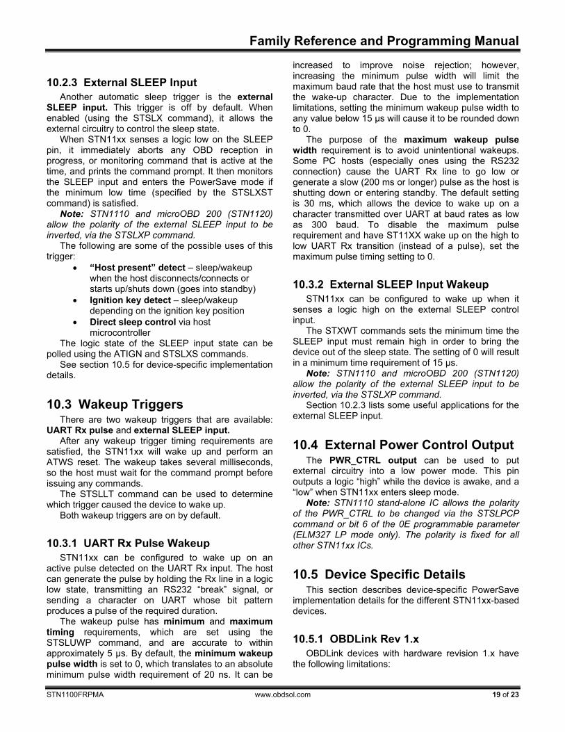
10.2.3 External SLEEP Input Another automatic sleep trigger is the external
SLEEP input. This trigger is off by default. When enabled (using the STSLX command), it allows the external circuitry to control the sleep state.
When STN11xx senses a logic low on the SLEEP pin, it immediately aborts any OBD reception in progress, or monitoring command that is active at the time, and prints the command prompt. It then monitors the SLEEP input and enters the PowerSave mode if the minimum low time (specified by the STSLXST command) is satisfied.
Note: STN1110 and microOBD 200 (STN1120) allow the polarity of the external SLEEP input to be inverted, via the STSLXP command.
The following are some of the possible uses of this trigger:
• “Host present” detect – sleep/wakeup when the host disconnects/connects or starts up/shuts down (goes into standby)
• Ignition key detect – sleep/wakeup depending on the ignition key position
• Direct sleep control via host microcontroller
The logic state of the SLEEP input state can be polled using the ATIGN and STSLXS commands.
See section 10.5 for device-specific implementation details.
10.3 Wakeup Triggers There are two wakeup triggers that are available:
UART Rx pulse and external SLEEP input. After any wakeup trigger timing requirements are
satisfied, the STN11xx will wake up and perform an ATWS reset. The wakeup takes several milliseconds, so the host must wait for the command prompt before issuing any commands.
The STSLLT command can be used to determine which trigger caused the device to wake up.
Both wakeup triggers are on by default.
10.3.1 UART Rx Pulse Wakeup STN11xx can be configured to wake up on an
active pulse detected on the UART Rx input. The host can generate the pulse by holding the Rx line in a logic low state, transmitting an RS232 “break” signal, or sending a character on UART whose bit pattern produces a pulse of the required duration.
The wakeup pulse has minimum and maximum timing requirements, which are set using the STSLUWP command, and are accurate to within approximately 5 μs. By default, the minimum wakeup pulse width is set to 0, which translates to an absolute minimum pulse width requirement of 20 ns. It can be
increased to improve noise rejection; however, increasing the minimum pulse width will limit the maximum baud rate that the host must use to transmit the wake-up character. Due to the implementation limitations, setting the minimum wakeup pulse width to any value below 15 μs will cause it to be rounded down to 0.
The purpose of the maximum wakeup pulse width requirement is to avoid unintentional wakeups. Some PC hosts (especially ones using the RS232 connection) cause the UART Rx line to go low or generate a slow (200 ms or longer) pulse as the host is shutting down or entering standby. The default setting is 30 ms, which allows the device to wake up on a character transmitted over UART at baud rates as low as 300 baud. To disable the maximum pulse requirement and have ST11XX wake up on the high to low UART Rx transition (instead of a pulse), set the maximum pulse timing setting to 0.
10.3.2 External SLEEP Input Wakeup STN11xx can be configured to wake up when it
senses a logic high on the external SLEEP control input.
The STXWT commands sets the minimum time the SLEEP input must remain high in order to bring the device out of the sleep state. The setting of 0 will result in a minimum time requirement of 15 μs.
Note: STN1110 and microOBD 200 (STN1120) allow the polarity of the external SLEEP input to be inverted, via the STSLXP command.
Section 10.2.3 lists some useful applications for the external SLEEP input.
10.4 External Power Control Output The PWR_CTRL output can be used to put
external circuitry into a low power mode. This pin outputs a logic “high” while the device is awake, and a “low” when STN11xx enters sleep mode.
Note: STN1110 stand-alone IC allows the polarity of the PWR_CTRL to be changed via the STSLPCP command or bit 6 of the 0E programmable parameter (ELM327 LP mode only). The polarity is fixed for all other STN11xx ICs.
10.5 Device Specific Details This section describes device-specific PowerSave
implementation details for the different STN11xx-based devices.
10.5.1 OBDLink Rev 1.x OBDLink devices with hardware revision 1.x have
the following limitations:
STN1100
20 of 23 www.obdsol.com STN1100FRPMA
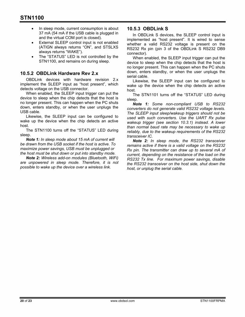
• In sleep mode, current consumption is about 37 mA (54 mA if the USB cable is plugged in and the virtual COM port is closed).
• External SLEEP control input is not enabled (ATIGN always returns “ON”, and STSLXS always returns “WAKE”).
• The “STATUS” LED is not controlled by the STN1100, and remains on during sleep.
10.5.2 OBDLink Hardware Rev 2.x OBDLink devices with hardware revision 2.x
implement the SLEEP input as “host present”, which detects voltage on the USB connector.
When enabled, the SLEEP input trigger can put the device to sleep when the chip detects that the host is no longer present. This can happen when the PC shuts down, enters standby, or when the user unplugs the USB cable.
Likewise, the SLEEP input can be configured to wake up the device when the chip detects an active host.
The STN1100 turns off the “STATUS” LED during sleep.
Note 1: In sleep mode about 15 mA of current will be drawn from the USB socket if the host is active. To maximize power savings, USB must be unplugged or the host must be shut down or put into standby mode.
Note 2: Wireless add-on modules (Bluetooth, WiFi) are unpowered in sleep mode. Therefore, it is not possible to wake up the device over a wireless link.
10.5.3 OBDLink S In OBDLink S devices, the SLEEP control input is
implemented as “host present”. It is wired to sense whether a valid RS232 voltage is present on the RS232 Rx pin (pin 3 of the OBDLink S RS232 DB9 connector).
When enabled, the SLEEP input trigger can put the device to sleep when the chip detects that the host is no longer present. This can happen when the PC shuts down, enters standby, or when the user unplugs the serial cable.
Likewise, the SLEEP input can be configured to wake up the device when the chip detects an active host.
The STN1101 turns off the “STATUS” LED during sleep.
Note 1: Some non-compliant USB to RS232 converters do not generate valid RS232 voltage levels. The SLEEP input sleep/wakeup triggers should not be used with such converters. Use the UART Rx pulse wakeup trigger (see section 10.3.1) instead. A lower than normal baud rate may be necessary to wake up reliably, due to the wakeup requirements of the RS232 transceiver IC.
Note 2: In sleep mode, the RS232 transceiver remains active if there is a valid voltage on the RS232 Rx pin. The transmitter can draw up to several mA of current, depending on the resistance of the load on the RS232 Tx line. For maximum power savings, disable the RS232 transceiver on the host side, shut down the host, or unplug the serial cable.
Family Reference and Programming Manual
STN1100FRPMA www.obdsol.com 21 of 23
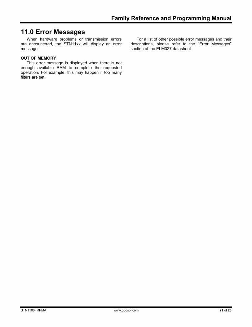
11.0 Error Messages When hardware problems or transmission errors
are encountered, the STN11xx will display an error message. OUT OF MEMORY
This error message is displayed when there is not enough available RAM to complete the requested operation. For example, this may happen if too many filters are set.
For a list of other possible error messages and their descriptions, please refer to the “Error Messages” section of the ELM327 datasheet.

STN1100
22 of 23 www.obdsol.com STN1100FRPMA
Appendix A: Revision History Revision A (October 28, 2009) Initial release of this document.
Family Reference and Programming Manual
STN11XXDSB www.obdsol.com 23 of 23
Appendix B: Contact Information OBD Solutions 1819 W Rose Garden Ln Ste 3 Phoenix, AZ 85027 United States Phone: +1 623.434.5506 Fax: +1 623.321.1628 Email: [email protected] Web: www.obdsol.com