Embed Size (px)
Citation preview
Stormwater Best Management Practice
(BMP) Selection and Implementation
January, 2003
Stormwater BMP Selection and Implementation
Midwest Research Institute
Funding for this program was made possible through a Section 319 Nonpoint Source Management Program grant from the U. S. Environmental Protection Agency through a contract with the Stormwater/Nonpoint Source Management Section of the Florida Department of Environmental Protection, the Florida Community College Consortium for Pollution Prevention Education and Midwest Research Institute.
Stormwater BMP Selection and Implementation
Table of Contents
i
Table of Contents Introduction ................................................................................................. 1 Construction Site Best Management Practices – Summary Chart ....................... 5 Construction Site Best Management Practices – Details .................................... 8
1 Temporary Gravel Entrance.............................................................. 8 2 Construction Road Stabilization....................................................... 10 3 Coagulant / Water Treatment Polyacrylamide (PAM) ........................ 12 4 Temporary Sediment Basin ............................................................ 15 5 Temporary Sediment Trap ............................................................. 19 6 Silt Fence ..................................................................................... 21 7 Storm Drain Inlet Protection........................................................... 24 8 Temporary Fill Diversions............................................................... 28 9 Diversion Dike............................................................................... 29 10 Temporary Slope Drain .................................................................. 31 11 Temporary Check Dams................................................................. 33 12 Dewatering................................................................................... 35 13 Floating Turbidity Barrier ............................................................... 37 14 Tree Preservation and Protection .................................................... 39 15 Temporary Seeding / Sodding / Mulching ........................................ 41 16 Vegetative Streambank Stabilization ............................................... 43
Permanent Stormwater Best Management Practices – Summary Chart ............ 45 Permanent Stormwater Best Management Practices – Details ......................... 49
17 Wet Detention Basins .................................................................... 49 18 Retention/Infiltration Basins ........................................................... 52 19 Infiltration / Exfiltration Trenches ................................................... 54 20 Grassed Waterways & Swales......................................................... 56 21 Landscape Retention (Bio-Retention) .............................................. 58 22 Underdrains and Stormwater Filter Systems..................................... 59 23 Stormwater Conveyance Channel.................................................... 61 24 Diversion ...................................................................................... 63 25 Level Spreader .............................................................................. 65 26 Check Dam................................................................................... 66 27 Waterway Drop Structure............................................................... 68
Stormwater BMP Selection and Implementation
Table of Contents
ii
Table of Contents (continued) 28 Outlet Protection ........................................................................... 70 29 Riprap .......................................................................................... 71 30 Porous Pavement .......................................................................... 72 31 Concrete Grid and Modular Pavement ............................................. 74 32 Paved Flume................................................................................. 76 33 Cellular Concrete Block .................................................................. 77 34 Grid Confinement Systems ............................................................. 79 35 Baffle Boxes.................................................................................. 81 36 Liquid / Solid Separators ................................................................ 83 37 Surface Roughening ...................................................................... 85 38 Trees / Shrubs / Vines and Ground Covers ...................................... 87
Housekeeping Best Management Practices – Summary Chart ......................... 90 Housekeeping Best Management Practices – Details ...................................... 91
39 Fertilizer Management ................................................................... 91 40 Litter Control................................................................................. 94 41 Catch Basin Cleaning ..................................................................... 95 42 Street Sweeping............................................................................ 96
References ................................................................................................. 97
Stormwater BMP Selection and Implementation
Introduction
Page 1
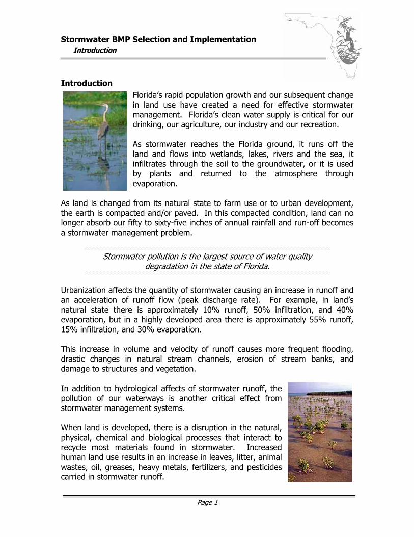
Introduction Florida’s rapid population growth and our subsequent change in land use have created a need for effective stormwater management. Florida’s clean water supply is critical for our drinking, our agriculture, our industry and our recreation. As stormwater reaches the Florida ground, it runs off the land and flows into wetlands, lakes, rivers and the sea, it infiltrates through the soil to the groundwater, or it is used by plants and returned to the atmosphere through evaporation.
As land is changed from its natural state to farm use or to urban development, the earth is compacted and/or paved. In this compacted condition, land can no longer absorb our fifty to sixty-five inches of annual rainfall and run-off becomes a stormwater management problem.
Stormwater pollution is the largest source of water quality degradation in the state of Florida.
Urbanization affects the quantity of stormwater causing an increase in runoff and an acceleration of runoff flow (peak discharge rate). For example, in land’s natural state there is approximately 10% runoff, 50% infiltration, and 40% evaporation, but in a highly developed area there is approximately 55% runoff, 15% infiltration, and 30% evaporation. This increase in volume and velocity of runoff causes more frequent flooding, drastic changes in natural stream channels, erosion of stream banks, and damage to structures and vegetation. In addition to hydrological affects of stormwater runoff, the pollution of our waterways is another critical effect from stormwater management systems. When land is developed, there is a disruption in the natural, physical, chemical and biological processes that interact to recycle most materials found in stormwater. Increased human land use results in an increase in leaves, litter, animal wastes, oil, greases, heavy metals, fertilizers, and pesticides carried in stormwater runoff.
Stormwater BMP Selection and Implementation
Introduction
Page 2
This creates high pollutant loading of:
Suspended Solids Includes sediment and decayed plant material that clogs waterways, smother bottom-living aquatic organisms, and increase turbidity
Oxygen Demanding Consume oxygen in the water, which may Substances lead to fish kills Nutrients Such as nitrogen & phosphorus that cause
unwanted and uncontrolled growth of algae and aquatic weeds
Pathogenic Bacteria Can contaminate lakes and shellfish waters to
prevent swimming and harvesting Heavy Metals Such as lead, cadmium, chromium, copper,
and zinc that can disrupt the reproduction of fish and shellfish and accumulate in fish tissues
Oil and Grease Toxic to many aquatic organisms Excessive Fresh Changes the salinity of estuaries and there-Water fore alters the types of organisms able to live in this critical nursery area
The goals of Florida’s stormwater management system are to provide flood protection, maintain or improve water quality, control erosion and sedimentation, and, as much as possible, allow for recreation facilities, open spaces, aesthetics, and stormwater reuse.
Florida was the first state in the country to implement a comprehensive stormwater management system in 1979 to help meet the goals stated above. The Florida stormwater management program has been and continues to be reviewed, updated, and improved to this present time. A recent change has been the permit streamline legislation, which requires an environmental resource
Stormwater BMP Selection and Implementation
Introduction
Page 3
permit (ERP) from the appropriate water management district for any proposed land use changes. This permitting aids in determining new/changed land use affects on stormwater quality, stormwater quantity and wetland impact. Permits are granted based on demonstrating the ability to meet a set of three performance standards and use of best management practices (BMPs) to achieve those standards. These standards are comprised of insuring that: 1) the peak discharge rate, 2) the volume and 3) the pollution load of stormwater leaving a site after development are no greater than before development.
A Best Management Practice (BMP) is defined as:
“a control technique used for a given set of conditions to achieve water quality and quantity at a minimum price.”
BMPs are implemented during construction and development of a new area and are operational after development. BMPs can be nonstructural – to improve stormwater quality by reducing the generation of runoff and the generation and accumulation of potential stormwater pollutants at or near their sources (e.g., wetlands protection, fertilizer control, street cleaning, etc.) – or structural – used to control stormwater volume and peak discharge in addition to reducing the magnitude of pollutants (e.g., vegetation, swales, retention basins, etc.).
BMPs should be combined together to make up a “BMP treatment train”. This term describes a stormwater management system in which the individual BMPs are the cars making up the train – the more BMPs incorporated into the system, the better the performance of the treatment train.
On-line BMPs are those that temporarily store all of the runoff from a storm before discharging to surface waters. Off-line BMPs divert the “treatment volume” (typically the first inch of runoff) of polluted stormwater for treatment and isolate it from the remaining stormwater.
Stormwater BMP Selection and Implementation
Introduction
Page 4
While we get about 120 storms a year, nearly 90% of them have less than one inch of rainfall. By capturing the first one inch of runoff, up to 90% of the pollution can be treated. Off-line BMPs should be used for all infiltration systems, and for most types of filter systems. Carefully selected and implemented best management practices can effectively maintain or improve Florida’s water quality.
There are numerous BMPs that can be used during all phases of development. These phases include:
1. Erosion and sediment control during construction throughout the period of site development
2. Permanent stormwater management BMPs to treat the stormwater after site development is completed.
3. Housekeeping to reduce pollutants in the finished stormwater management system
This manual provides an overview of the most effective BMPs for each of these three phases. Preceding each section (Construction BMPs, Permanent Stormwater BMPs, and Housekeeping BMPs) is a summary chart that provides a quick comparative reference regarding the cost, effectiveness, maintenance requirements, etc. of each BMP. Details for each BMP are then provided to address planning, design, construction, and maintenance considerations. Further details about BMP implementation and associated Florida Department of Environmental Protection (DEP) guidelines can be found in “The Florida Development Manual: A Guide to Sound Land and Water Management” published by the Florida DEP in 1988 and in “The Stormwater, Erosion, and Sedimentation Control Inspector’s Manual” published by the Florida DEP in 1999.
Stormwater BMP Selection and Implementation
Construction Site BMPs – Summary Chart
Page 5
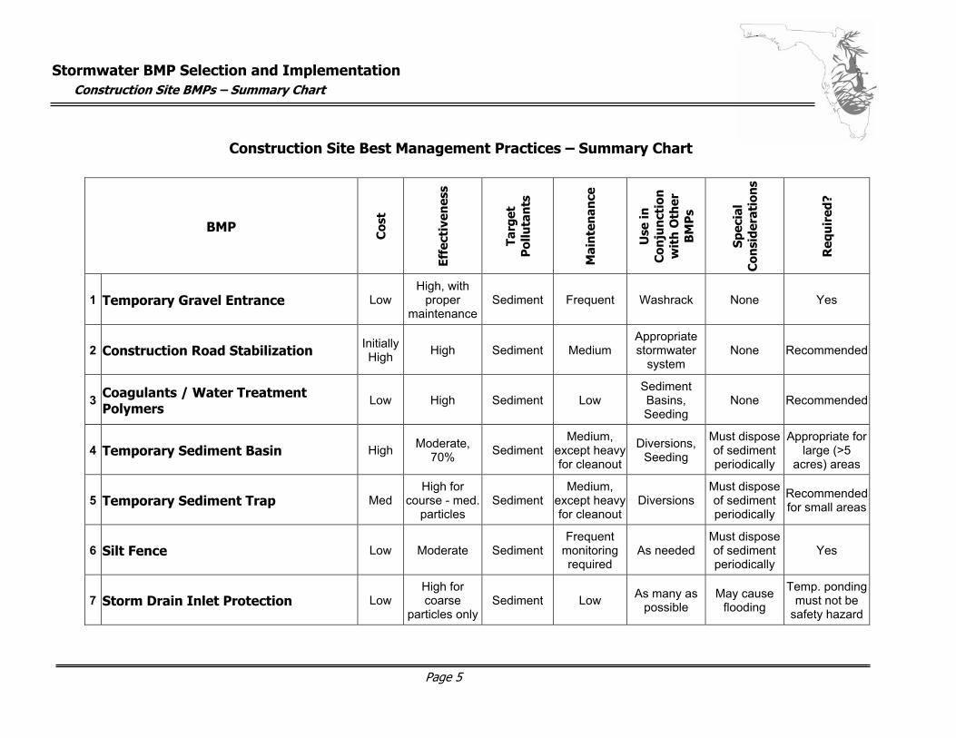
Construction Site Best Management Practices – Summary Chart
BMP
Cos
t
Effe
ctiv
enes
s
Targ
et
Pol
luta
nts
Mai
nte
nan
ce
Use
in
Con
jun
ctio
n
wit
h O
ther
B
MP
s
Spec
ial
Con
side
rati
ons
Req
uir
ed?
1 Temporary Gravel Entrance Low High, with
proper maintenance
Sediment Frequent Washrack None Yes
2 Construction Road Stabilization Initially High High Sediment Medium
Appropriate stormwater
system None Recommended
3 Coagulants / Water Treatment Polymers
Low High Sediment Low Sediment Basins, Seeding
None Recommended
4 Temporary Sediment Basin High Moderate, 70% Sediment
Medium, except heavy for cleanout
Diversions, Seeding
Must dispose of sediment periodically
Appropriate for large (>5
acres) areas
5 Temporary Sediment Trap Med High for
course - med. particles
Sediment Medium,
except heavy for cleanout
Diversions Must dispose of sediment periodically
Recommended for small areas
6 Silt Fence Low Moderate Sediment Frequent
monitoring required
As needed Must dispose of sediment periodically
Yes
7 Storm Drain Inlet Protection Low High for coarse
particles onlySediment Low As many as
possible May cause
flooding
Temp. ponding must not be
safety hazard
Stormwater BMP Selection and Implementation
Construction Site BMPs – Summary Chart
Page 6
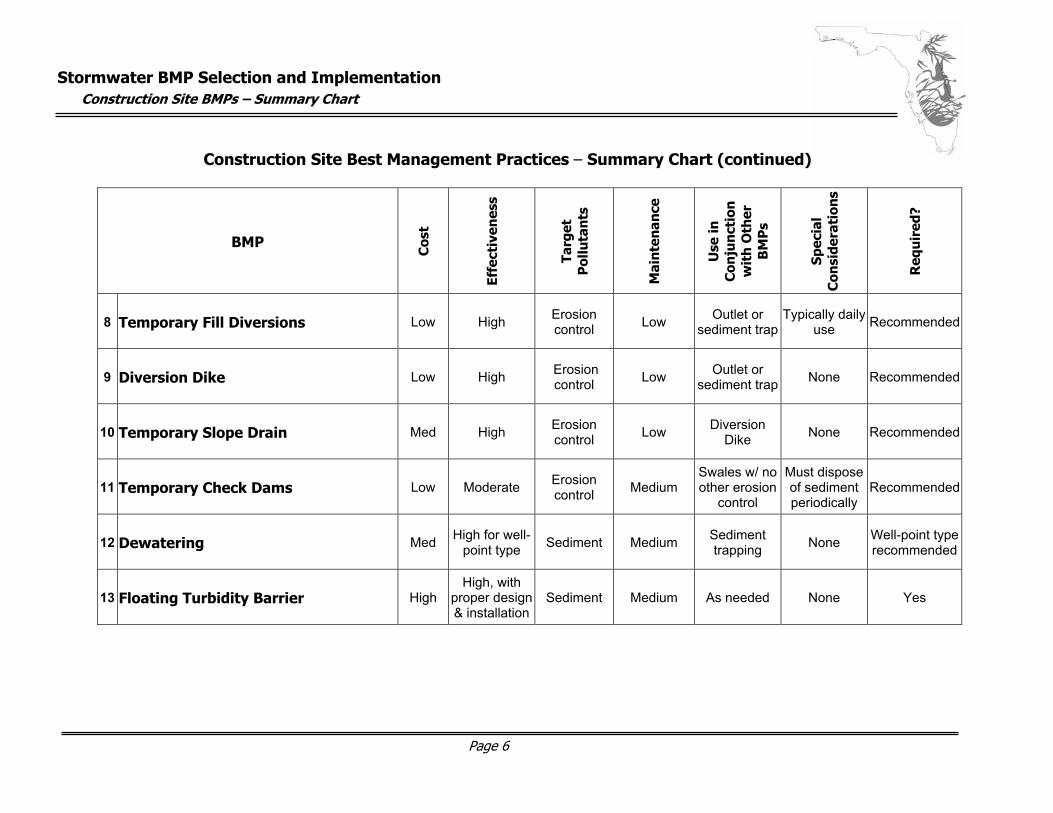
Construction Site Best Management Practices – Summary Chart (continued)
BMP
Cos
t
Effe
ctiv
enes
s
Targ
et
Pol
luta
nts
Mai
nte
nan
ce
Use
in
Con
jun
ctio
n
wit
h O
ther
B
MP
s
Spec
ial
Con
side
rati
ons
Req
uir
ed?
8 Temporary Fill Diversions Low High Erosion control Low Outlet or
sediment trapTypically daily
use Recommended
9 Diversion Dike Low High Erosion control Low Outlet or
sediment trap None Recommended
10 Temporary Slope Drain Med High Erosion control Low Diversion
Dike None Recommended
11 Temporary Check Dams Low Moderate Erosion control Medium
Swales w/ no other erosion
control
Must dispose of sediment periodically
Recommended
12 Dewatering Med High for well-point type Sediment Medium Sediment
trapping None Well-point type recommended
13 Floating Turbidity Barrier High High, with
proper design & installation
Sediment Medium As needed None Yes
Stormwater BMP Selection and Implementation
Construction Site BMPs – Summary Chart
Page 7
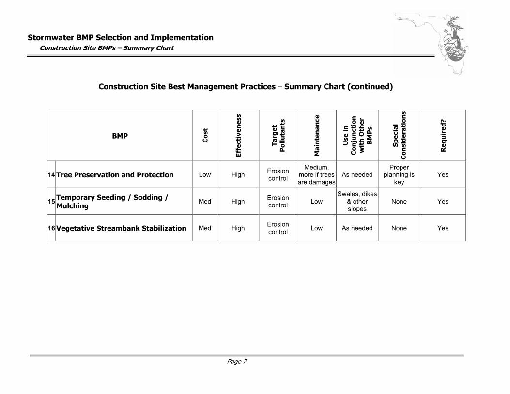
Construction Site Best Management Practices – Summary Chart (continued)
BMP
Cos
t
Effe
ctiv
enes
s
Targ
et
Pol
luta
nts
Mai
nte
nan
ce
Use
in
Con
jun
ctio
n
wit
h O
ther
B
MP
s
Spec
ial
Con
side
rati
ons
Req
uir
ed?
14 Tree Preservation and Protection Low High Erosion control
Medium, more if trees are damages
As needed Proper
planning is key
Yes
15 Temporary Seeding / Sodding / Mulching
Med High Erosion control Low
Swales, dikes & other slopes
None Yes
16 Vegetative Streambank Stabilization Med High Erosion control Low As needed None Yes
Stormwater BMP Selection and Implementation
Construction Site BMPs
Page 8
Construction Site Best Management Practices – Details Construction site sediment and erosion control BMPs are used to protect existing water quality. Although most construction sites will have some effect on water quality, proper control practices can minimize this effect. Because sediment carries the largest volume of pollutants, it is critical to trap sediment before it is carried off site. It is also important to stabilize construction sites and prevent erosion as soon as possible.
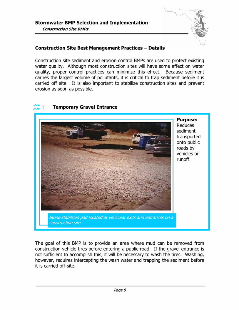
1 Temporary Gravel Entrance
The goal of this BMP is to provide an area where mud can be removed from construction vehicle tires before entering a public road. If the gravel entrance is not sufficient to accomplish this, it will be necessary to wash the tires. Washing, however, requires intercepting the wash water and trapping the sediment before it is carried off-site.
Stone stabilized pad located at vehicular exits and entrances on a construction site.
Purpose: Reduces sediment transported onto public roads by vehicles or runoff.
graphic here…
Stormwater BMP Selection and Implementation
Construction Site BMPs
Page 9
Site Preparation The entrance area should be chosen to provide maximum access to all construction vehicles. This area should be cleared of all vegetation, roots, etc. Utilizing a geotextile mat will improve stability and simplify maintenance. Drainage facilities (such as wash racks) should be installed according to approved specifications and manufacturer’s recommendations. Construction Materials The entranceway should be constructed of FDOT No. 1 Coarse Aggregate (1.5 – 3.5 inch stone). Wood chips may be used in residential construction if they can be restrained from floating away during rainstorms. Construction Plan / Design Considerations The length of the entrance must be at least 50 feet and must widen at its connection to the roadway to accommodate the turning radius of large trucks. The aggregate layer must be at least 6 inches thick and extend the full width of the entrance area. Maintenance
Periodic top dressing with 2-inch stone may be required to keep the entrance area in a condition that prevents tracking or flow of mud onto public rights-of-way. Any structures used to trap sediments should be cleaned out or
repaired as required. The paved road should be swept daily for sediment and stones. Spilled, dropped, washed materials or those tracked by vehicles onto
roads must be moved immediately. If there is evidence of construction vehicles “cutting corners” where
gravel meets the roadway, the entrance area should be adjusted accordingly.
Stormwater BMP Selection and Implementation
Construction Site BMPs
Page 10
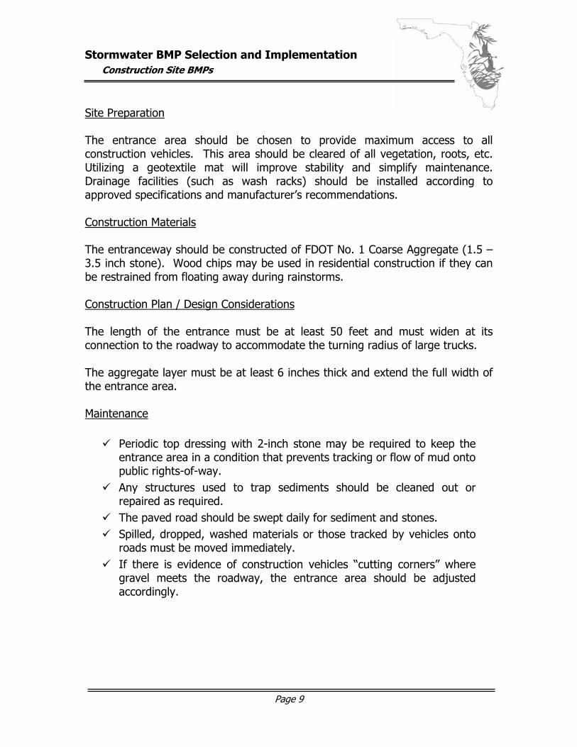
2 Construction Road Stabilization
During wet weather, construction roads may become virtually unusable due to the runoff waters flowing on their surfaces. Stabilizing these roads with stone can raise initial costs but will eventually make the roads more usable and act as part of the final base course of the road. Site Preparation Temporary access roadbeds and parking surfaces should be cleared of all vegetation, roots, etc. and a stormwater system will be provided, as necessary, and designed according to regulations. Construction access roads should follow the contour of natural terrain as much as possible with slopes not exceeding 10 percent. Parking areas will be located on naturally flat areas with grades sufficient to provide drainage, but not exceeding 4 percent.
The temporary stabilization of access roads, subdivision roads, parking areas, and other on-site vehicle transportation routes with stone immediately after grading.
Purpose: Reduces erosion and degradation of roadbeds due to construction traffic and wet weather. Also minimizes regarding requirements.
graphic here…
Stormwater BMP Selection and Implementation
Construction Site BMPs
Page 11
Construction Materials After grading or completion of utility installation within right-of-way, a filter fabric may be applied, according to manufacturer’s specifications, for additional stability, followed by a 6-inch course of FDOT No. 1 aggregate. Roadside ditches, cuts, fills, and disturbed areas adjacent to construction parking lots and roads should be stabilized with appropriate vegetation. Construction Plan / Design Considerations Roadbeds must be 14 feet wide for one-way traffic and 20 feet wide for two-way traffic. The recommended side slopes for cuts and fills: 2:1 or flatter for clay soils, 3:1 or flatter for sandy soils Maintenance
Periodic top dressing with new gravel. Inspection of adjacent seeded areas to insure vigorous stand of
vegetation is maintained. Inspection of ditches and/or other drainage structures to insure they
are not clogged with silt or other debris.
Stormwater BMP Selection and Implementation
Construction Site BMPs
Page 12
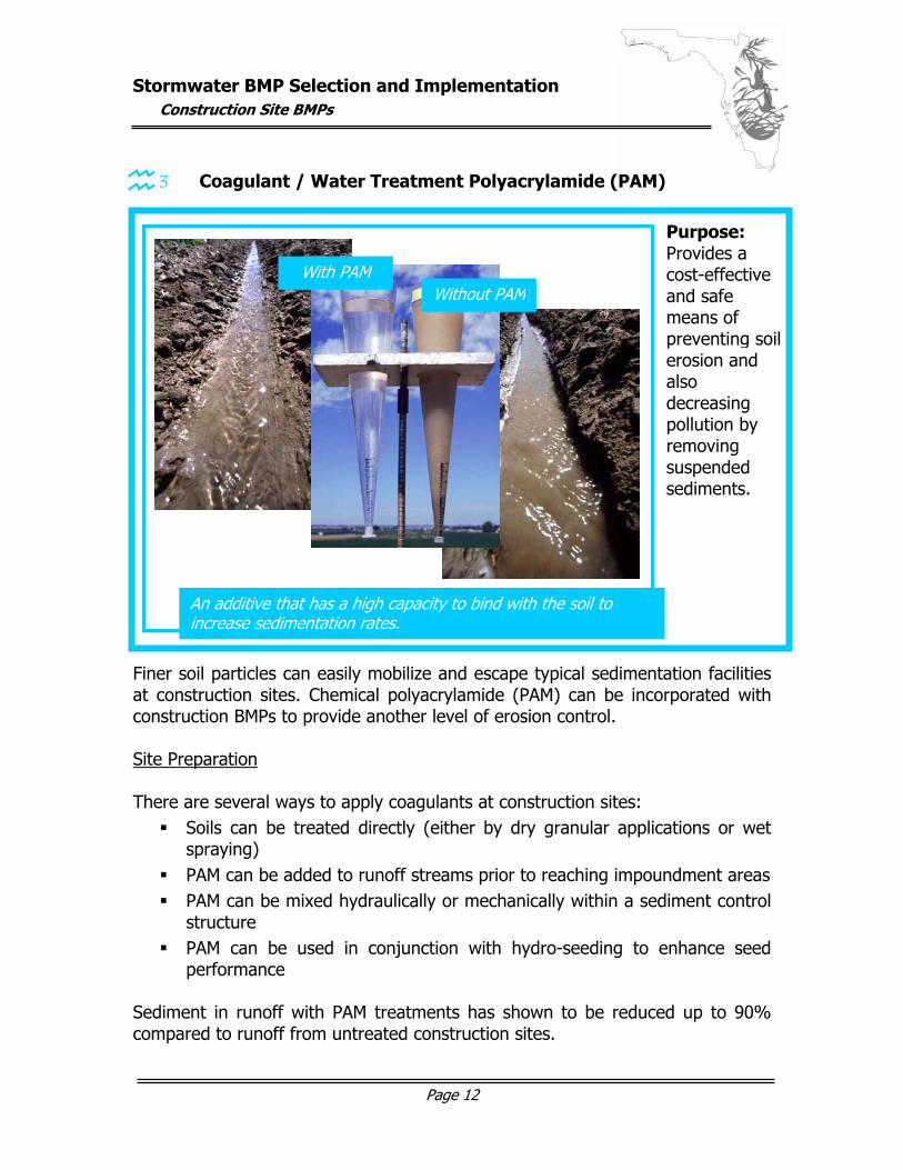
3 Coagulant / Water Treatment Polyacrylamide (PAM) Finer soil particles can easily mobilize and escape typical sedimentation facilities at construction sites. Chemical polyacrylamide (PAM) can be incorporated with construction BMPs to provide another level of erosion control. Site Preparation There are several ways to apply coagulants at construction sites: Soils can be treated directly (either by dry granular applications or wet
spraying) PAM can be added to runoff streams prior to reaching impoundment areas PAM can be mixed hydraulically or mechanically within a sediment control
structure PAM can be used in conjunction with hydro-seeding to enhance seed
performance Sediment in runoff with PAM treatments has shown to be reduced up to 90% compared to runoff from untreated construction sites.
An additive that has a high capacity to bind with the soil to increase sedimentation rates.
Purpose: Provides a cost-effective and safe means of preventing soil erosion and also decreasing pollution by removing suspended sediments.
Without PAMWith PAM
Stormwater BMP Selection and Implementation
Construction Site BMPs
Page 13
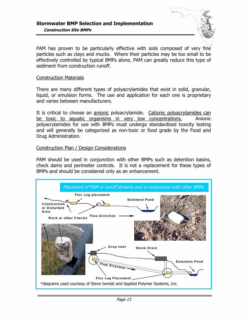
PAM has proven to be particularly effective with soils composed of very fine particles such as clays and mucks. Where their particles may be too small to be effectively controlled by typical BMPs alone, PAM can greatly reduce this type of sediment from construction runoff. Construction Materials There are many different types of polyacrylamides that exist in solid, granular, liquid, or emulsion forms. The use and application for each one is proprietary and varies between manufacturers. It is critical to choose an anionic polyacrylamide. Cationic polyacrylamides can be toxic to aquatic organisms in very low concentrations. Anionic polyacrylamides for use with BMPs must undergo standardized toxicity testing and will generally be categorized as non-toxic or food grade by the Food and Drug Administration. Construction Plan / Design Considerations PAM should be used in conjunction with other BMPs such as detention basins, check dams and perimeter controls. It is not a replacement for these types of BMPs and should be considered only as an enhancement.
Placement of PAM in runoff streams and in conjunction with other BMPs
*diagrams used courtesy of Steve Iwinski and Applied Polymer Systems, Inc.
Stormwater BMP Selection and Implementation
Construction Site BMPs
Page 14
Polyacrylamide performance is directly linked to the soil type to which it is applied. A soil sample should be sent to the PAM manufacturer to determine the best match. This can greatly reduce the amount of PAM required to treat a defined area. The least amount of PAM possible should be used to achieve optimal performance. The pH of the water in the area to be treated should be tested and compared with manufacturer’s recommendations – pH can impact the effectiveness of PAMs. Care must be taken to prevent spills of coagulants and clean-up must be accomplished according to manufacturer’s established procedures. PAM and water mixtures may become slippery and can pose a safety hazard. Routine dust protection safety measures should be used when handling granular forms of PAM.
Maintenance
No removal of applied coagulants is required.
Sediment levels at the bottom of sediment control structures should be monitored to measure any loss of storage capacity due to enhanced sedimentation.
Sediments should be removed once they have diminished the storage capacity by 10%.
Stormwater BMP Selection and Implementation
Construction Site BMPs
Page 15
4 Temporary Sediment Basin
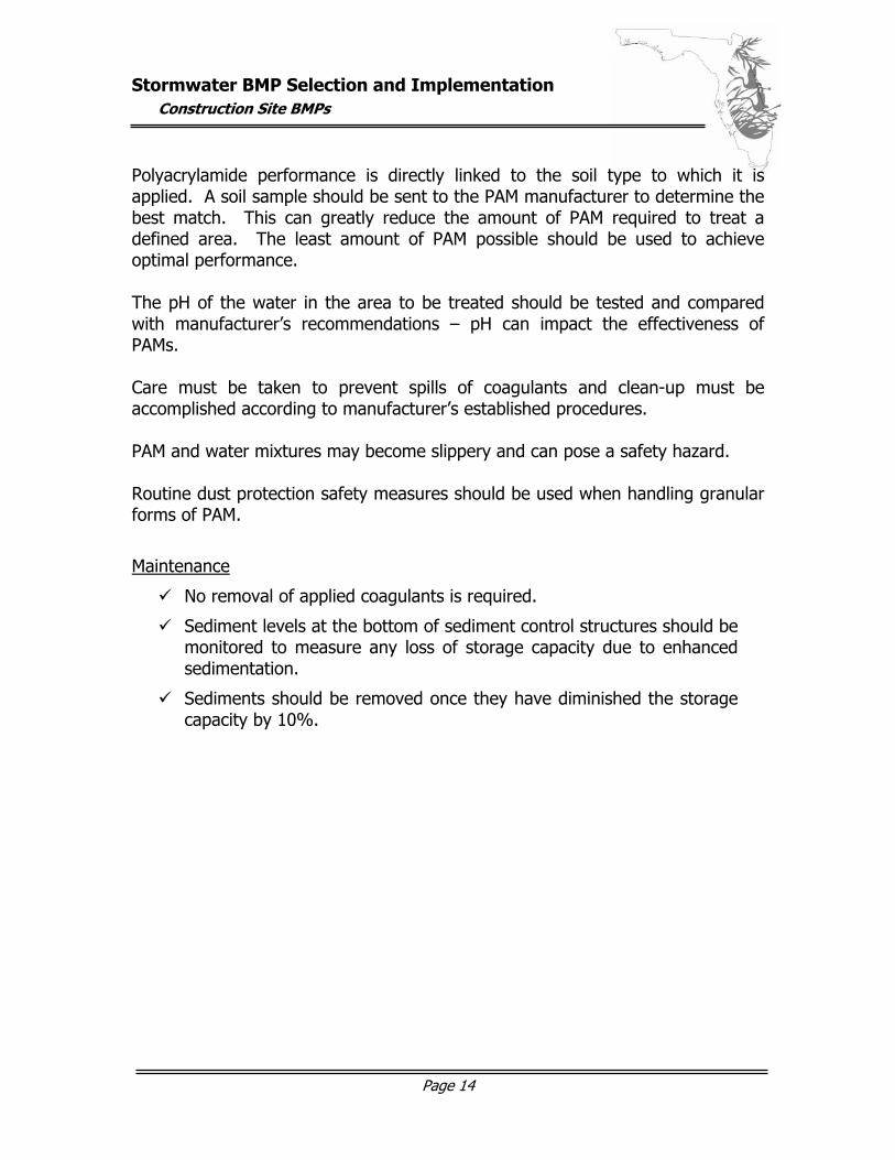
A temporary sediment basin is, at best, only 70% - 80% effective and should be used in conjunction with other BMPs such as temporary seeding, diversion dikes, etc. Coagulants such as PAM (refer to previous section) can be added to the water in sediment basins to greatly increase their effectiveness.
The maximum allowable drainage area into the basin is 150 acres, unless it is to be a permanent pond, which must be designed by a professional engineer. If the temporary basin is not designed as a permanent pond, it must be dismantled, with the embankment and sediment appropriately disposed, after the construction effort has been completed (usually a period less than two years). If a sediment basin is to become a permanent pond, the sediment must be removed prior to its permanent use. Permanent pond construction is beyond the scope of this BMP. The temporary basin should consist of an excavated pool area, an embankment, and spillways (designed to pass the entire peak flow from a ten-year storm).
A temporary basin (that may be professionally designed as a permanent structure) with a stormwater release structure, formed by constructing an embankment of compacted soil across a drainageway.
Purpose: Detains runoff laden with sediment, from an area greater than 5 acres, long enough for most of the sediment to settle out.
graphic here…
Stormwater BMP Selection and Implementation
Construction Site BMPs
Page 16
The spillways may be a principal spillway acting alone or, ideally, a principal and emergency spillway acting together. Site Preparation The sediment basin should be located to intercept the largest possible amount of runoff from the disturbed area, before entering a water boom. It is critical to locate the basin such that its failure will not result in loss of life, damage to adjacent properties, or interruption of use of public roads or utilities. Inlet(s) to the sediment basin should be chosen or modified to minimize turbulence that will disturb the settling conditions of the basin. Areas under the embankment and any structures must be cleared, grubbed, and stripped of topsoil to remove trees, vegetation and roots. The pool area must be cleared of all brush and trees. Construction Materials The design of the principal spillway may be chosen from many configurations, but will typically consist of a trash rack and anti-vortex device at the inlet, a riser (corrugated metal pipe or slotted PVC for small discharge requirements), an anchored concrete or steel base, a conduit/barrel (usually corrugated metal pipe) through the embankment, appropriate anti-seep collars or filter diaphragms along the discharge conduit, and outlet protection (such as riprap), as required. Perforated drains in the bottom of the basin pool, designed according to specifications, or small orifices (less than four inches in diameter) in the risers, above the maximum sediment levels, may be used for dewatering the temporary basin. The emergency spillway, an open channel next to the embankment, should be excavated in undisturbed soil and not over fill that has not been compacted. The embankment fill should be composed of clean mineral soil that has adequate strength, low permeability and piping resistance typical to water-impounding structures. The moisture content of the fill should not allow a ball formed in the hand to readily crumble. The fill must be layered and compacted according to Florida Department of Environmental Protection (DEP) guidelines. Temporary vegetation should be used to stabilize the embankment and emergency spillway within 15 days of completing the sediment basin.
Stormwater BMP Selection and Implementation
Construction Site BMPs
Page 17
Construction Plan / Design Considerations The temporary sediment basin should be constructed to maintain a permanent pool of water for maximum effectiveness. The capacity of the basin must be at least 134 cubic yards per acre of drainage area measured from the bottom of the basin to the crest of the principal spillway. The basin shape must have an effective flow length twice the effective flow width. Baffles may be used in conjunction with shape to accomplish this. A clean out level must be calculated and clearly marked on the riser. This represents a reduction of the volume of the basin to 55 cubic yards per acre. The cleanout level must not be higher than one foot below the top of the riser. A principal spillway and emergency spillway should be used in conjunction to discharge the runoff expected from a ten-year storm. The principal spillway must discharge at least 0.2 cubic feet per second per acre of the drainage area if the water surface is at the crest of the emergency spillway. The principal spillway should be a minimum of one foot below the crest of the emergency spillway (or three feet below the top of the embankment, if no emergency spillway is used). There must be a minimum freeboard of one foot between the design high water and the top of the embankment. The emergency spillway channel should be located to avoid sharp turns or bends and to discharge the water flow to a defined channel downstream from the embankment. The design high water through the emergency spillway must be at least one foot below the top of the embankment. There must be a 20-foot level control section in the emergency spillway that is at the highest area of the spillway. The emergency spillway must return flow to the natural channel at a non-eroding velocity. The embankment must have a minimum top width of eight feet. With side slopes of 2:1 or flatter, the maximum height is ten feet. With side lopes of 2.5:1 or flatter, the maximum height is 15 feet.
Maintenance
Monitoring to insure the cleanout level marked on the riser has not been reached. Proper removal and disposal of sediment when the cleanout level is
reached. Inspection of the embankment to ensure structural integrity.

Stormwater BMP Selection and Implementation
Construction Site BMPs
Page 18
Inspection of emergency spillway to ensure erosion-resistance. Removal of structure after disturbance of area is complete, effective
time performance period not to exceed two years.
Stormwater BMP Selection and Implementation
Construction Site BMPs
Page 19
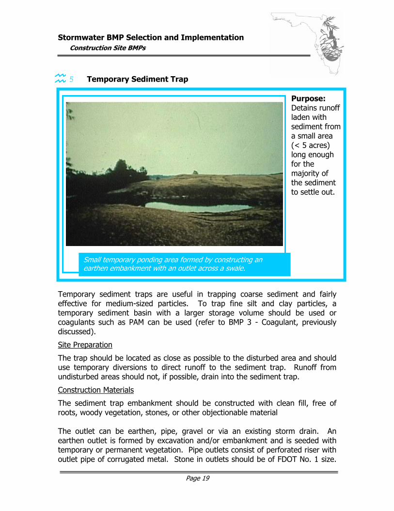
5 Temporary Sediment Trap Temporary sediment traps are useful in trapping coarse sediment and fairly effective for medium-sized particles. To trap fine silt and clay particles, a temporary sediment basin with a larger storage volume should be used or coagulants such as PAM can be used (refer to BMP 3 - Coagulant, previously discussed).
Site Preparation
The trap should be located as close as possible to the disturbed area and should use temporary diversions to direct runoff to the sediment trap. Runoff from undisturbed areas should not, if possible, drain into the sediment trap.
Construction Materials
The sediment trap embankment should be constructed with clean fill, free of roots, woody vegetation, stones, or other objectionable material The outlet can be earthen, pipe, gravel or via an existing storm drain. An earthen outlet is formed by excavation and/or embankment and is seeded with temporary or permanent vegetation. Pipe outlets consist of perforated riser with outlet pipe of corrugated metal. Stone in outlets should be of FDOT No. 1 size.
Small temporary ponding area formed by constructing an earthen embankment with an outlet across a swale.
Purpose: Detains runoff laden with sediment from a small area (< 5 acres) long enough for the majority of the sediment to settle out.
graphic here…
Stormwater BMP Selection and Implementation
Construction Site BMPs
Page 20
A filter fabric can be installed inside the gravel filter to improve sediment-trapping efficiency, but may increase the probability of clogging the outlet.
Construction Plan / Design Considerations
Sediment traps must have initial storage volume of 134 cubic yards per acre of drainage area. Side slopes of excavated traps should be no steeper than 2:1. Embankment heights must not exceed five feet. Top widths are dependent on heights according to DEP guidelines. Slopes shall be 2:1 or flatter. Sediment trap outlets must be capable of handling the runoff from a ten-year storm without significant failure or erosion. Pipe outlets should be constructed in such a way that the top of the embankment is one and a half feet above the crest of the riser. The top 2/3 of the riser should be perforated with ½-inch diameter holes. Pipe sizing and perforation spacing should be according to Florida DEP guidelines. Gravel outlets should consist of a crushed stone section located at the low point of the embankment. Their length should be at least six times the number of acres in the drainage area. The crest of a gravel outlet should be one foot below the top of the embankment. Traps can also be constructed to effectively collect below the levels of existing storm drains and then utilize those facilities as outlets, per Florida DEP guidelines.
Maintenance
Removal of sediment when it fills half of the capacity of the sediment trap. Cleaning outlet if it becomes clogged with sediment. Inspection of structure for damage or poor operation after significant
runoff occurs. Inspection of height of outlet to insure it remains at least one foot
below the embankment top. Removal of structure after stabilization of drainage area, performance
period not to exceed 18 months.
Stormwater BMP Selection and Implementation
Construction Site BMPs
Page 21
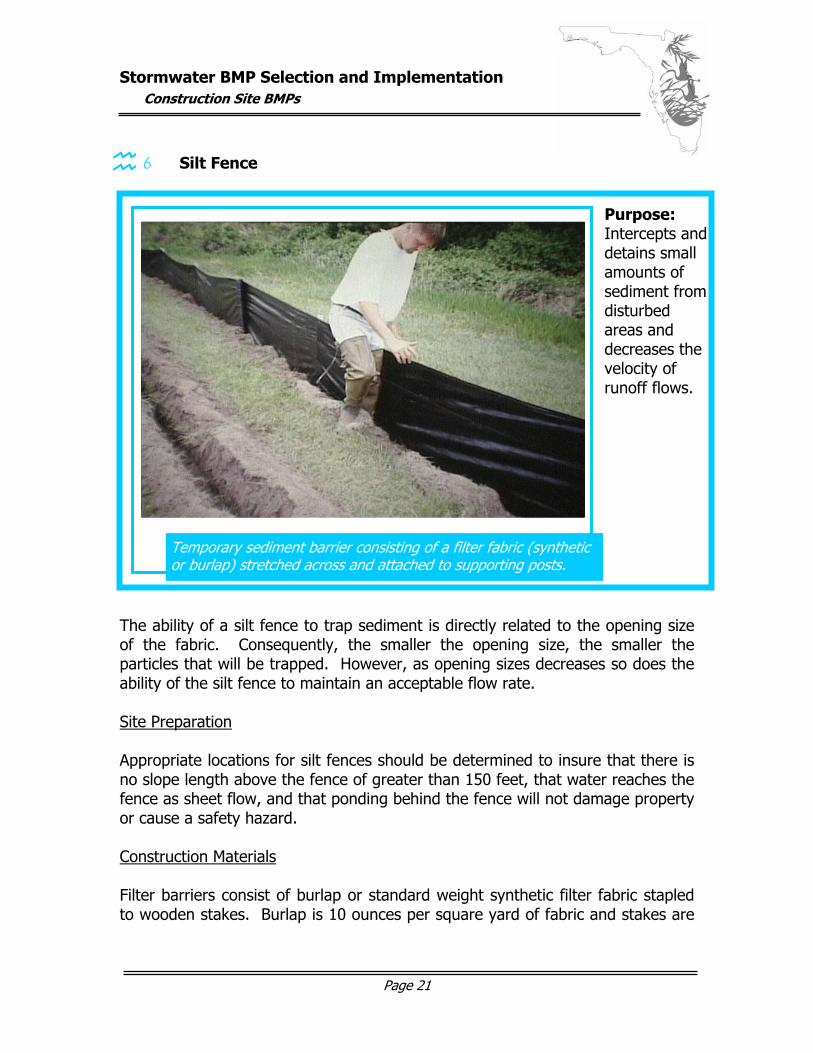
6 Silt Fence The ability of a silt fence to trap sediment is directly related to the opening size of the fabric. Consequently, the smaller the opening size, the smaller the particles that will be trapped. However, as opening sizes decreases so does the ability of the silt fence to maintain an acceptable flow rate. Site Preparation Appropriate locations for silt fences should be determined to insure that there is no slope length above the fence of greater than 150 feet, that water reaches the fence as sheet flow, and that ponding behind the fence will not damage property or cause a safety hazard. Construction Materials Filter barriers consist of burlap or standard weight synthetic filter fabric stapled to wooden stakes. Burlap is 10 ounces per square yard of fabric and stakes are
Temporary sediment barrier consisting of a filter fabric (synthetic or burlap) stretched across and attached to supporting posts.
Purpose: Intercepts and detains small amounts of sediment from disturbed areas and decreases the velocity of runoff flows.
graphic here…
Stormwater BMP Selection and Implementation
Construction Site BMPs
Page 22
1” x 2” wood (or less desirable, metal equivalent) with a minimum length of three feet. Silt fences consist of wire support fence with attached synthetic filter fabric. Synthetic fabric shall be pervious sheet of propylene, nylon, polyester, or polyethylene yarn. These fabrics will contain ultraviolet ray inhibitors and stabilizers to provide a minimum of 6 months of expected usable construction life. Posts of wood (4-inch diameter) or steel (1.33 pounds per linear foot) shall have projections for fastening wire to them. Attached wire reinforcement shall be a minimum of 36 inches in height, 14-gauge, with a maximum mesh spacing of six inches. Construction Plan / Design Considerations Silt fences should never be constructed in live streams or where flows are likely to exceed one cubic foot per second. Silt fences should only be used where drainage area is less than ¼ acre per 100 lineal feet of fence. Lengths of fences should be less than 600 feet (if more than 600 feet is needed, multiple fences should be constructed as independent units). Filter barriers of burlap and stakes are fairly effective and inexpensive, but silt fences with synthetic filter fabric slow flow rates significantly and have a higher filtering efficiency. Although permeability rates vary for woven and non-woven synthetic fabric types, all these fabrics demonstrate high filtering efficiencies for sandy sediments. Filter barriers have an expected usable life of three months and silt fences have an expected usable life of six months. The most effective installation configuration is two parallel silt fences spaced a minimum of three feet apart. Fences should be installed on the contour (instead of up and down) of any hills and such that flow cannot bypass the ends of the fence. Fence fabric, posts and wire supports must be sufficient such that they are strong enough to withstand loads from ponding water and trapped sediment. Installation of silt fences must be in accordance with Florida DEP guidelines. Maintenance
Immediate inspection after runoff events and at least daily during prolonged rainfall.
Stormwater BMP Selection and Implementation
Construction Site BMPs
Page 23
Required repairs carried out immediately to maintain fence effectiveness. Removal of sediment when deposits equal half the height of the fence
(or a second fence may be installed). Replacement of fences as they approach their expected useful lives. After silt fence is removed, grading, preparation and seeding of any
remaining sediment deposits.
Stormwater BMP Selection and Implementation
Construction Site BMPs
Page 24
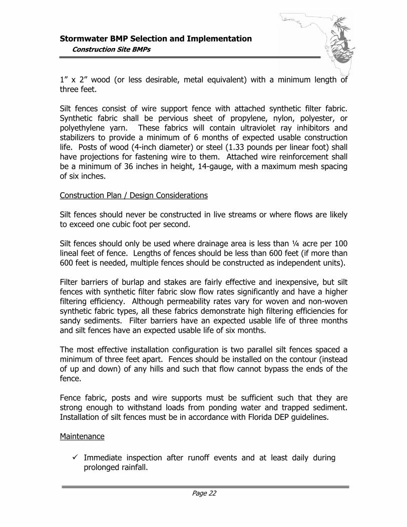
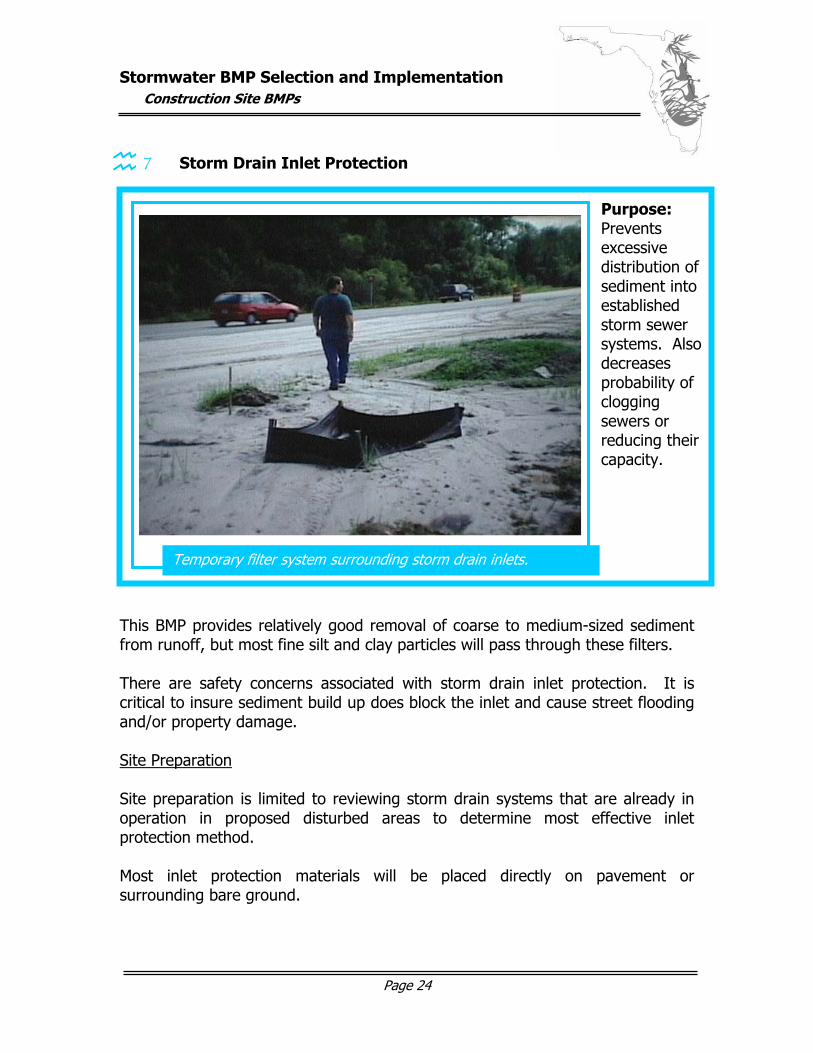
7 Storm Drain Inlet Protection This BMP provides relatively good removal of coarse to medium-sized sediment from runoff, but most fine silt and clay particles will pass through these filters. There are safety concerns associated with storm drain inlet protection. It is critical to insure sediment build up does block the inlet and cause street flooding and/or property damage. Site Preparation Site preparation is limited to reviewing storm drain systems that are already in operation in proposed disturbed areas to determine most effective inlet protection method. Most inlet protection materials will be placed directly on pavement or surrounding bare ground.
Temporary filter system surrounding storm drain inlets.
Purpose: Prevents excessive distribution of sediment into established storm sewer systems. Also decreases probability of clogging sewers or reducing their capacity.
graphic here…
Stormwater BMP Selection and Implementation
Construction Site BMPs
Page 25
Construction Materials Materials vary with the type on inlet protection to be implemented as follows: Straw Bales ............................... Wire-bound or string-tied bales with side
oriented bindings, stakes and/or rebar, loose straw, and gravel
Fabric Drop ............................... Fabric from continuous rolls, wood (preferred)
or metal stakes, and heavy duty staples Gravel and Wire Mesh Drop ........ Hardware cloth or wire mesh with ½ inch
openings, and FDOT No. 1 coarse aggregate (1.5” to 3.5” stone)
Block and Gravel Drop................ Concrete blocks, wire mesh or hardware cloth
with ½ inch openings, and suitably coarse stone
Sod Drop .................................. Appropriately prepared sod Prefabricated Internal Drop ....... Filter insert to be placed under grate of catch
basin Prefabricated External Drop ....... Filter secured over the grate or directly to
concrete around opening Gravel Curb............................... Hardware cloth or wire mesh with ½ inch
openings, FDOT No. 1 coarse aggregate, and overflow weir of 2” x 4” boards to lessen ponding
Block and Gravel Curb................ Concrete blocks, 2” x 4” board, wire mesh or
hardware cloth with ½ inch openings, and FDOT No. 1 coarse aggregate – or – gravel filled burlap bags
Curb and Gutter Barrier .............. Gravel filled burlap bags
Stormwater BMP Selection and Implementation
Construction Site BMPs
Page 26
Construction Plan / Design Considerations This practice should be limited to sites with a drainage area of less than 1 acre and only be placed in areas where it will not result in a safety hazard. Each of the storm drain inlet protection methods described by this BMP should be installed in accordance with detailed Florida DEP guidelines. The design considerations / construction plans for each protection type is as follows: Straw Bales ............................... Do not use if adjacent area is paved. Bales will
be entrenched (min. depth four inches) and placed lengthwise in a tight single row surrounding the inlet. Bales will be secured by two stakes or rebar per bale with loose straw wedged between the bales. Gravel may be spread around bales to improve stability.
Fabric Drop ............................... Stakes to be spaced around perimeter of inlet
with a wood frame for stability and a surrounding trench. Burlap will be attached to stakes and extended into trench, which will be backfilled and compacted over burlap.
Gravel and Wire Mesh Drop ........ Wire mesh to be laid over drop inlet to extend
one foot beyond each side of structure. Stone will be placed over mesh with depth equal to at least 12 inches and extending beyond the opening by at least 18 inches. Due to lack of overflow mechanism, ponding is likely.
Block and Gravel Drop................ Concrete blocks will be placed lengthwise in a
single row around inlet perimeter up to 24 inches high. Wire mesh will be placed outside the block vertical openings with stone piled against the wire to the top of the block barrier.
Sod Drop .................................. Sod placed to form a turf mat covering the soil
for a distance for four feet from each side of the inlet structure.
Stormwater BMP Selection and Implementation
Construction Site BMPs
Page 27
Prefabricated Internal Drop ....... Remove the inlet grate to place the prefabricated filter and secure the grate hold it in position. Note: Removal and cleaning using heavy lifting equipment is required when sediment reaches within one foot of the grate.
Prefabricated External Drop ....... Prefabricated filter may be secured by toggle
bolt (to inlet grate) or bolted directly to concrete. Note: Maintenance is required when sediment reaches within one foot of the top of the device.
Gravel Curb............................... Wire mesh to be placed over curb inlet
openings so wire extends 12 inches across top of inlet cover and 12 inches across concrete gutter from inlet opening. Stone will be piled to secure mesh and to completely cover opening. An overflow space may be constructed at the top of the curb using 2” x 4” boards.
Block and Gravel Curb................ Two concrete blocks to be placed on sides at
either end of inlet opening, board placed through outer holes to form overflow space in front of inlet. More concrete blocks to be placed against board with wire mesh covering blocks and stone piled against mesh.
Curb and Gutter Barrier .............. Gravel filled burlap bags to be layered and
packed tightly around curb inlet on gently sloping street segments. If stacking several bags high, leave a gap to provide overflow spillway.
Maintenance
Inspection and repair of structures as necessary. Removal of sediment and clearing of filter mechanisms as clogging
becomes apparent. Removal of structures when drainage area has been properly
stabilized.
Stormwater BMP Selection and Implementation
Construction Site BMPs
Page 28
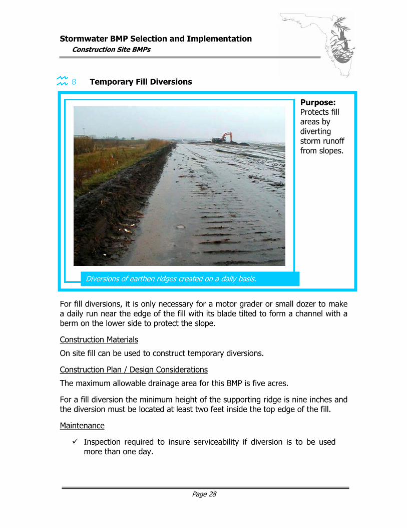
8 Temporary Fill Diversions
Add photo! Temporary fill diversions provide slope protection on a daily basis as fill work proceeds from the bottom to the top, with the elevation constantly changing. Site Preparation Diversions can be easily constructed with equipment used for site grading to create an earthen filled ridge. For fill diversions, it is only necessary for a motor grader or small dozer to make a daily run near the edge of the fill with its blade tilted to form a channel with a berm on the lower side to protect the slope.
Construction Materials
On site fill can be used to construct temporary diversions.
Construction Plan / Design Considerations
The maximum allowable drainage area for this BMP is five acres.
For a fill diversion the minimum height of the supporting ridge is nine inches and the diversion must be located at least two feet inside the top edge of the fill.
Maintenance
Inspection required to insure serviceability if diversion is to be used more than one day.
Diversions of earthen ridges created on a daily basis.
Purpose: Protects fill areas by diverting storm runoff from slopes.
Stormwater BMP Selection and Implementation
Construction Site BMPs
Page 29
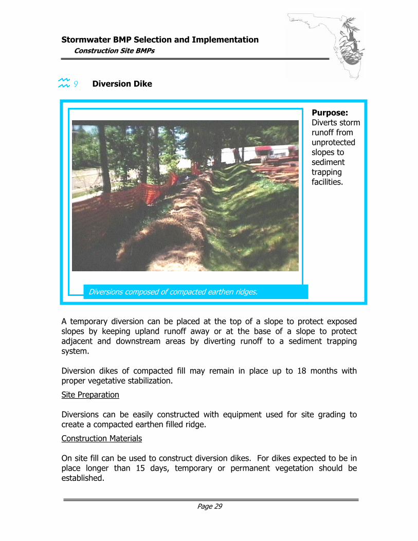
9 Diversion Dike A temporary diversion can be placed at the top of a slope to protect exposed slopes by keeping upland runoff away or at the base of a slope to protect adjacent and downstream areas by diverting runoff to a sediment trapping system. Diversion dikes of compacted fill may remain in place up to 18 months with proper vegetative stabilization.
Site Preparation Diversions can be easily constructed with equipment used for site grading to create a compacted earthen filled ridge.
Construction Materials On site fill can be used to construct diversion dikes. For dikes expected to be in place longer than 15 days, temporary or permanent vegetation should be established.
Diversions composed of compacted earthen ridges.
graphic here…
Purpose: Diverts storm runoff from unprotected slopes to sediment trapping facilities.
Stormwater BMP Selection and Implementation
Construction Site BMPs
Page 30
Construction Plan / Design Considerations The maximum allowable drainage area for this BMP is five acres. For a diversion dike the minimum allowable height is 18 inches with a base width of 4.5 feet. Side slopes should be 3:1 or flatter. Maintenance
Inspection of diversion dikes after every storm, or at least weekly, and repair as necessary. Immediate repairs of damages from conventional construction
equipment operations.
Stormwater BMP Selection and Implementation
Construction Site BMPs
Page 31
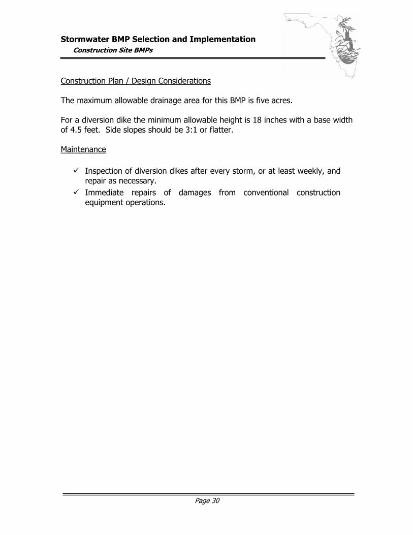
10 Temporary Slope Drain Because of the time lag between grading a slope and installation of permanent drainage structures to dispose of runoff, slopes are vulnerable to severe gully erosion. Slope drains used in conjunction with a diversion can prevent this type of erosion. Site Preparation The slope drain area should be chosen so that it is placed on undisturbed soil or well-compacted fill with a slope toward the drain of with a minimum rate of ½ inch per foot. Construction Materials Conduit should consist of heavy-duty material manufactured for this purpose with grommets for anchoring at a spacing of ten feet or less. The diversion dike is constructed from compacted earth, the outlet should be stabilized by a riprap apron or similar system.
Flexible tubing or conduit extending from the top to the bottom of a cut or fill slope.
Purpose: Temporarily conveys concentrated stormwater runoff down a slope without causing erosion on or below the slope.
graphic here…
Stormwater BMP Selection and Implementation
Construction Site BMPs
Page 32
Construction Plan / Design Considerations The drainage area should not exceed five acres. The conduit, entrance section, accompanying diversion dike, and stabilized outlet must be sized, designed and installed according to standard Florida DEP guidelines. The soil around and under the entrance must be hand-tamped in eight inch lifts to the top of the dike to prevent piping failure around the inlet. The grommets must be used to stake the drain to the slope and the sections of the drain must be securely fastened together with watertight fittings. Maintenance
Inspection on a weekly basis and after every storm with appropriate repairs being made. Marking to insure construction traffic across the drain is prevented.
Stormwater BMP Selection and Implementation
Construction Site BMPs
Page 33
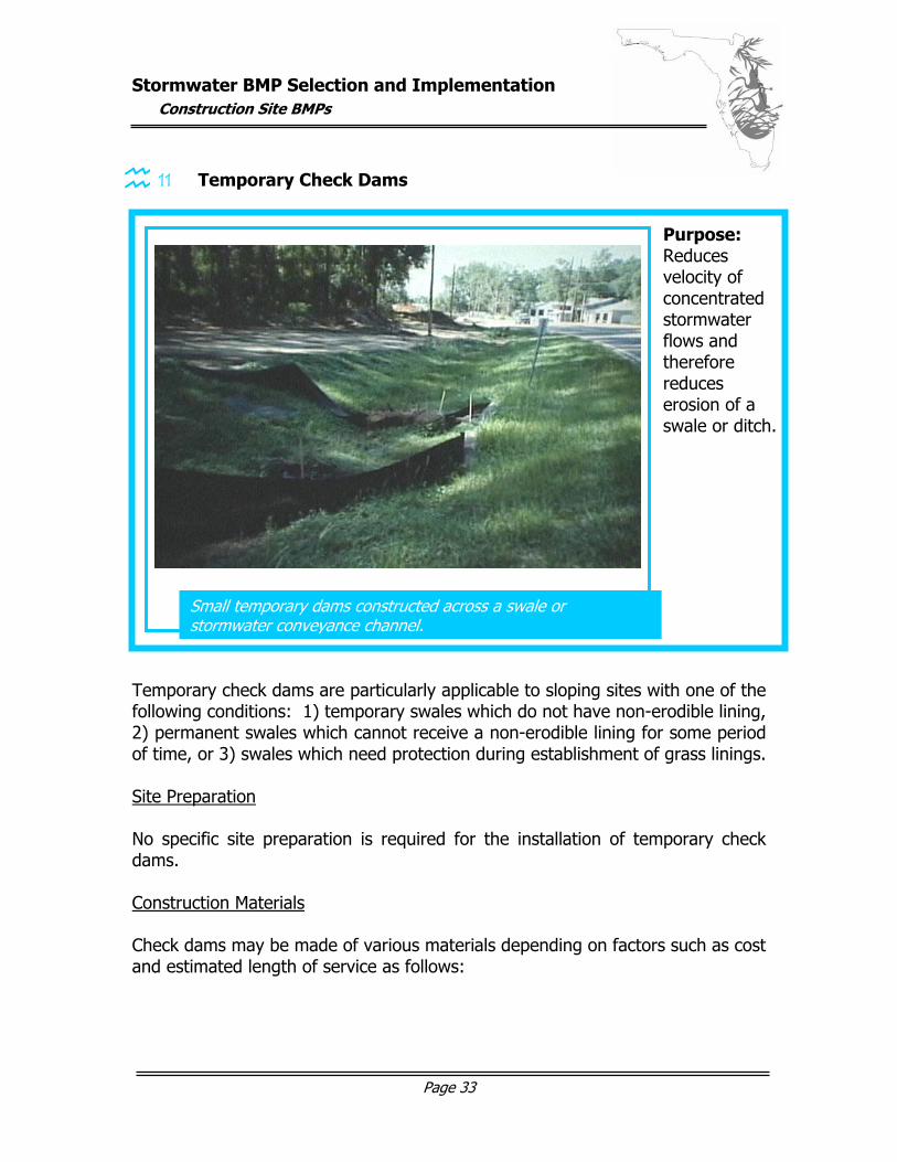
11 Temporary Check Dams Temporary check dams are particularly applicable to sloping sites with one of the following conditions: 1) temporary swales which do not have non-erodible lining, 2) permanent swales which cannot receive a non-erodible lining for some period of time, or 3) swales which need protection during establishment of grass linings. Site Preparation No specific site preparation is required for the installation of temporary check dams. Construction Materials Check dams may be made of various materials depending on factors such as cost and estimated length of service as follows:
Small temporary dams constructed across a swale or stormwater conveyance channel.
Purpose: Reduces velocity of concentrated stormwater flows and therefore reduces erosion of a swale or ditch.
graphic here…
Stormwater BMP Selection and Implementation
Construction Site BMPs
Page 34
Straw Bales (short term, lowest cost)
Bound bales with wood for staking.
Logs (longer term, low cost, more labor to install)
Four to six inch logs, salvaged from construction site, if possible. Logs and/or brush to be placed downstream to prevent scour during high flows.
Stones (longer term, higher cost, easy to install)
FDOT No. 1 coarse aggregate, 1.5 to 3.5 inch stone.
Construction Plan / Design Considerations The drainage area of the ditch or swale being protected should not exceed ten acres. The maximum height of the check dam is two feet. The center of the check dam must be at least six inches lower than the outer edges. The maximum spacing between dams should be such that the toe of the upstream dam is at the same elevation as the top of the downstream dam. Dams constructed of logs, stone, or straw bales with filter fences must be constructed according to Florida DEP guidelines. Maintenance
Inspection for sediment accumulation and appropriate removal and disposal of sediment before it reaches one-half the original height of the dam. Correction of any erosion around edges of dams. Removal of the dam structure, clearing and stabilization of dam area.
Stormwater BMP Selection and Implementation
Construction Site BMPs
Page 35
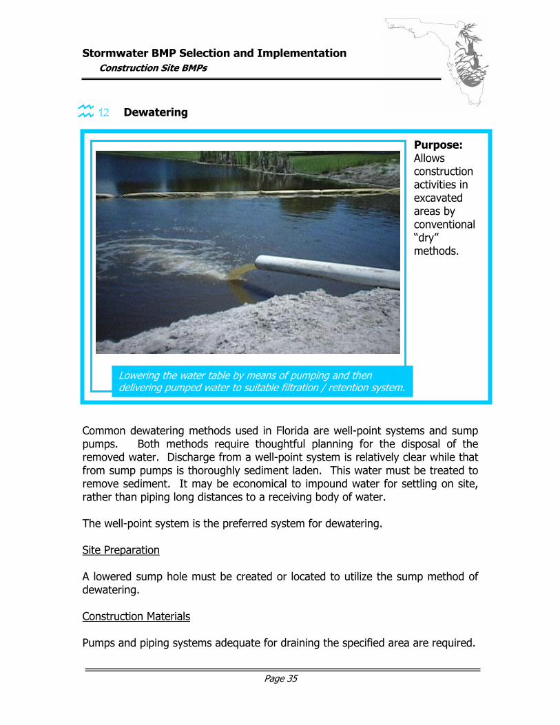
12 Dewatering Common dewatering methods used in Florida are well-point systems and sump pumps. Both methods require thoughtful planning for the disposal of the removed water. Discharge from a well-point system is relatively clear while that from sump pumps is thoroughly sediment laden. This water must be treated to remove sediment. It may be economical to impound water for settling on site, rather than piping long distances to a receiving body of water. The well-point system is the preferred system for dewatering. Site Preparation A lowered sump hole must be created or located to utilize the sump method of dewatering. Construction Materials Pumps and piping systems adequate for draining the specified area are required.
Lowering the water table by means of pumping and then delivering pumped water to suitable filtration / retention system.
Purpose: Allows construction activities in excavated areas by conventional “dry” methods.
graphic here…
Stormwater BMP Selection and Implementation
Construction Site BMPs
Page 36
Construction Plan / Design Considerations The well-point system consists of one or more rows of small two inch collector pipes which are jetted vertically into the ground near the proposed excavation. The small pipes are connected by a larger six-inch manifold pipe, which is connected to the pump and discharge line. After the initial discharge, the water is generally clear and may be discharged directly into a receiving body of water. Sump systems direct water flow to sump hole where it is pumped out. This system transports all particle sizes, including mud, and must be thoroughly treated for sediment removal, even if filtering systems are included at the pump inlets and outlets. Maintenance
Inspection daily of water impoundment area. Frequent inspection and cleaning of pump filtration devices. Determination that there is no diminished performance of system and
facility continues ability to drain.
Stormwater BMP Selection and Implementation
Construction Site BMPs
Page 37
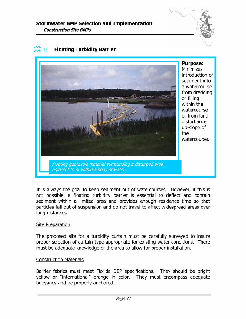
13 Floating Turbidity Barrier It is always the goal to keep sediment out of watercourses. However, if this is not possible, a floating turbidity barrier is essential to deflect and contain sediment within a limited area and provides enough residence time so that particles fall out of suspension and do not travel to affect widespread areas over long distances. Site Preparation The proposed site for a turbidity curtain must be carefully surveyed to insure proper selection of curtain type appropriate for existing water conditions. There must be adequate knowledge of the area to allow for proper installation. Construction Materials Barrier fabrics must meet Florida DEP specifications. They should be bright yellow or “international” orange in color. They must encompass adequate buoyancy and be properly anchored.
Floating geotextile material surrounding a disturbed area adjacent to or within a body of water.
Purpose: Minimizes introduction of sediment into a watercourse from dredging or filling within the watercourse or from land disturbance up-slope of the watercourse.
graphic here…
Stormwater BMP Selection and Implementation
Construction Site BMPs
Page 38
Construction Plan / Design Considerations This BMP relates only to minimal and moderate flow conditions where velocity of the flow reaches only five feet per second. For higher flow rates, qualified engineers should be involved in curtain selection and design. Turbidity curtains should not be installed across channel flows – they do not halt the movement of water itself, but are designed only to trap sediment. By constructing part of the curtain from a heavy woven filter fabric, water may pass through the curtain, but sediment particles are retained, during water movements such as high and low tides. There are numerous Florida DEP guidelines relating to the selection, installation and removal of floating turbidity barriers. They apply to differing conditions from protected areas to areas with considerable current, wind and/or wave action. These guidelines should be reviewed in detail prior to barrier selection. Maintenance
Inspection and repair, as necessary, to insure protection of watercourse. Sediment removal and appropriate disposal at end of project to restore
original water depth. Removal of the curtain to minimize turbidity
Stormwater BMP Selection and Implementation
Construction Site BMPs
Page 39
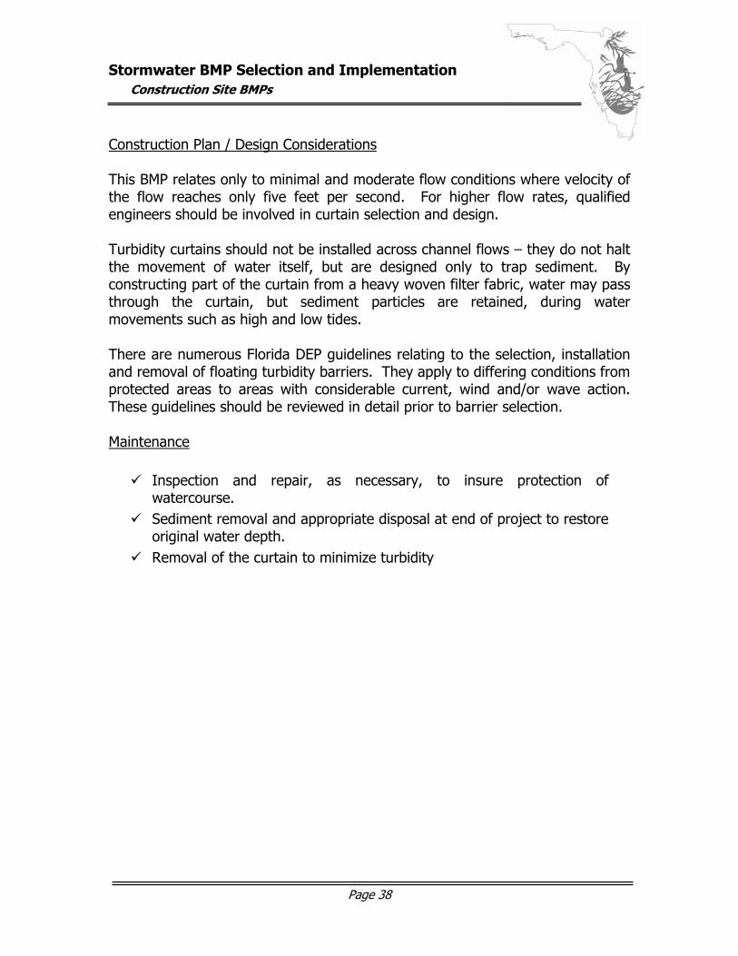
14 Tree Preservation and Protection Trees provide erosion and sediment control, watershed protection, landscape beautification, dust and pollution control, noise reduction, shade and benefits when land is converted from forest to urban-type uses. Site Preparation Proper planning is the easiest and most economical method to insure trees are adequately preserved. This can eliminate costly replacement or treatment of tree damage. Trees selected for retention should be accurately marked on building plans, marked appropriately prior to any work performed on-site, and discussed with all parties during the pre-construction conference. The limits of clearing around trees should lie outside the drip line (directly under the edges of the outermost branches) and never any closer than five feet to the trunk. Fences (refer to Florida DEP guidelines) are effective protection for roots, trunks, and tops of trees to be retained and fences must be used if the trees are within 40 feet of a proposed building or excavation. Construction Materials Appropriate fencing and marking materials should be used to accurately designate trees, and their root systems, that will be retained. Construction Plan / Design Considerations The following requirements should be taken into consideration when planning for tree preservation: Heavy equipment, vehicular traffic, or stockpiles of any construction
material (including topsoil) is not permissible within tree drip lines. Fires are not permitted within 100 feet of tree drip lines. No toxic materials can be stored within 100 feet of tree drip lines. Trenching should be done outside of crown spreads of trees, avoiding
large roots and filled (with peat moss enhanced soil) as soon as possible. Tunneling is preferred to trenching if it will preserve more of the root
system.
Protection of desirable trees during construction activities.
Purpose: Ensures survival of trees necessary for environmental benefits. graphic here…
Stormwater BMP Selection and Implementation
Construction Site BMPs
Page 40
Maintenance Care for trees, which are marked for preservation, must include:
Minimizing root exposure to air Smoothly cutting damaged roots and protecting them with tree wound
dressing Mulching and fertilizing Proportionally reducing the crown spread of trees in accordance with
any root damage Removal of any trees that have been damaged so badly they cannot
survive Aerating compacted soil over root zone Reparation of bark and limb damage
Stormwater BMP Selection and Implementation
Construction Site BMPs
Page 41
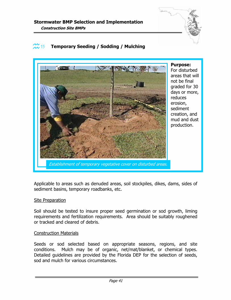
15 Temporary Seeding / Sodding / Mulching Applicable to areas such as denuded areas, soil stockpiles, dikes, dams, sides of sediment basins, temporary roadbanks, etc. Site Preparation Soil should be tested to insure proper seed germination or sod growth, liming requirements and fertilization requirements. Area should be suitably roughened or tracked and cleared of debris. Construction Materials Seeds or sod selected based on appropriate seasons, regions, and site conditions. Mulch may be of organic, net/mat/blanket, or chemical types. Detailed guidelines are provided by the Florida DEP for the selection of seeds, sod and mulch for various circumstances.
Establishment of temporary vegetative cover on disturbed areas.
Purpose: For disturbed areas that will not be final graded for 30 days or more, reduces erosion, sediment creation, and mud and dust production.
graphic here…
Stormwater BMP Selection and Implementation
Construction Site BMPs
Page 42
Construction Plan / Design Considerations Mulch should be applied in conjunction with any seeding operations in accordance with detailed Florida DEP guidelines. Seeds should be evenly applied with appropriate seeder. Sod may be placed as solid coverage or in spots and strips according to DEP guidelines. Note that sod placed in swales or waterways should be laid perpendicular to the direction of flow and should be pegged or stapled to resist washout. Maintenance
Reseeding is required if vegetative cover is not established. Proper irrigation, weeding, fertilization and mowing of sod are
required. Inspection of mulch after storm events is required to insure continued
coverage.
Stormwater BMP Selection and Implementation
Construction Site BMPs
Page 43
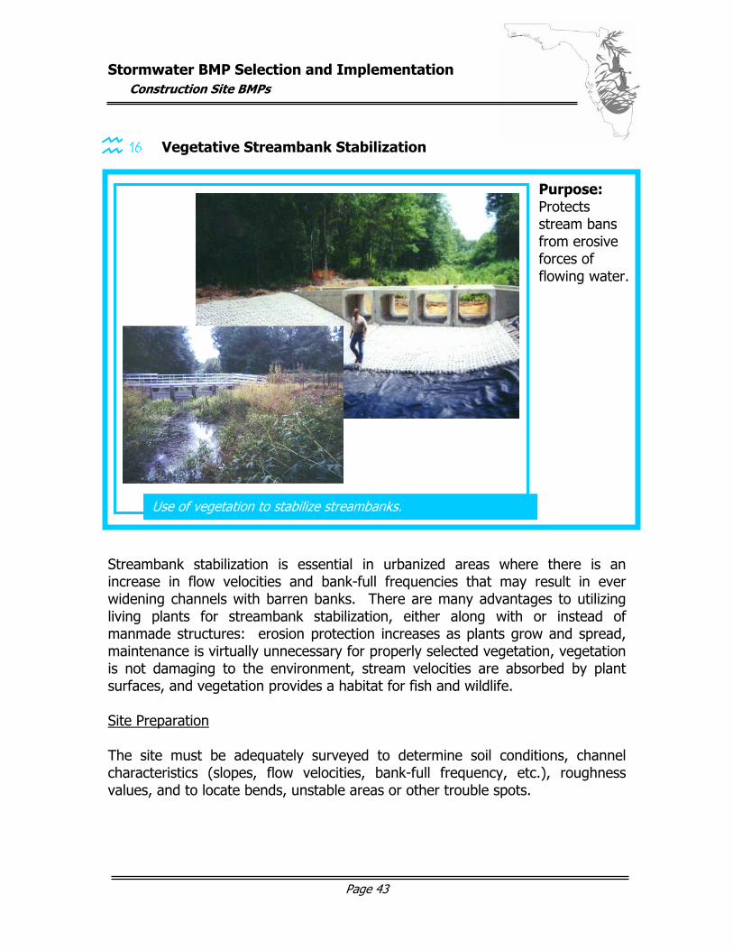
16 Vegetative Streambank Stabilization Streambank stabilization is essential in urbanized areas where there is an increase in flow velocities and bank-full frequencies that may result in ever widening channels with barren banks. There are many advantages to utilizing living plants for streambank stabilization, either along with or instead of manmade structures: erosion protection increases as plants grow and spread, maintenance is virtually unnecessary for properly selected vegetation, vegetation is not damaging to the environment, stream velocities are absorbed by plant surfaces, and vegetation provides a habitat for fish and wildlife. Site Preparation The site must be adequately surveyed to determine soil conditions, channel characteristics (slopes, flow velocities, bank-full frequency, etc.), roughness values, and to locate bends, unstable areas or other trouble spots.
Use of vegetation to stabilize streambanks.
Purpose: Protects stream bans from erosive forces of flowing water.
Stormwater BMP Selection and Implementation
Construction Site BMPs
Page 44
Construction Materials The type of vegetation to be planted depends on its proposed location on the streambank. The bottom of the channel is the aquatic plant zone that is permanently flooded and inhabited by plants such as alligator weed, hydrilla, and water lilies. The herbaceous flooded zone is only flooded about half the year and is typically inhabited by rushes, sedges, pickerel weed, cattails, etc. During periods of average high water the shrub zone is flooded. The shrub zone is inhabited by willows, red maples, button-bush and other plants with a high regenerative capacity. Trees from the oak family usually inhabit the infrequently flooded tree zone. To select the proper plants from each zone, it is necessary to review the detailed guidelines provided by the Florida DEP. Construction Plan / Design Considerations Vegetative stabilization should only be considered in areas where the bank-full velocity does not exceed five feet per second. If bank-full stream velocities approach the maximum allowable, riprap or other structural protection should be used on the outside of channel bends. Channel bottoms must be stable before banks can be stabilized. Permitting by state and federal agencies may be required. Maintenance
With proper plant selection and establishment, there should be virtually no maintenance requirements.
Stormwater BMP Selection and Implementation
Permanent Stormwater BMPs – Summary Chart
Page 45
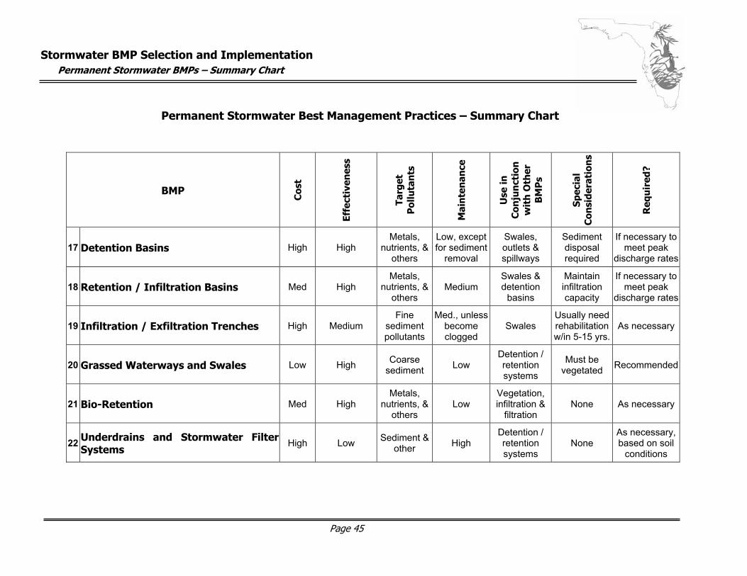
Permanent Stormwater Best Management Practices – Summary Chart
BMP
Cos
t
Effe
ctiv
enes
s
Targ
et
Pol
luta
nts
Mai
nte
nan
ce
Use
in
Con
jun
ctio
n
wit
h O
ther
B
MP
s
Spec
ial
Con
side
rati
ons
Req
uir
ed?
17 Detention Basins High High Metals,
nutrients, & others
Low, except for sediment
removal
Swales, outlets & spillways
Sediment disposal required
If necessary tomeet peak
discharge rates
18 Retention / Infiltration Basins Med High Metals,
nutrients, & others
Medium Swales & detention
basins
Maintain infiltration capacity
If necessary to meet peak
discharge rates
19 Infiltration / Exfiltration Trenches High Medium Fine
sediment pollutants
Med., unless become clogged
Swales Usually need rehabilitation w/in 5-15 yrs.
As necessary
20 Grassed Waterways and Swales Low High Coarse sediment Low
Detention / retention systems
Must be vegetated Recommended
21 Bio-Retention Med High Metals,
nutrients, & others
Low Vegetation, infiltration &
filtration None As necessary
22 Underdrains and Stormwater Filter Systems
High Low Sediment & other High
Detention / retention systems
None As necessary, based on soil
conditions
Stormwater BMP Selection and Implementation
Permanent Stormwater BMPs – Summary Chart
Page 46
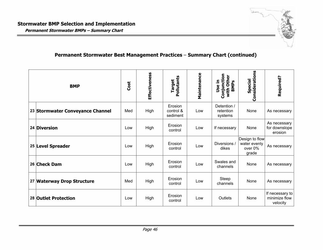
Permanent Stormwater Best Management Practices – Summary Chart (continued)
BMP
Cos
t
Effe
ctiv
enes
s
Targ
et
Pol
luta
nts
Mai
nte
nan
ce
Use
in
Con
jun
ctio
n
wit
h O
ther
B
MP
s
Spec
ial
Con
side
rati
ons
Req
uir
ed?
23 Stormwater Conveyance Channel Med High Erosion control & sediment
Low Detention / retention systems
None As necessary
24 Diversion Low High Erosion control Low If necessary None
As necessary for downslope
erosion
25 Level Spreader Low High Erosion control Low Diversions /
dikes
Design to flow water evenly
over 0% grade
As necessary
26 Check Dam Low High Erosion control Low Swales and
channels None As necessary
27 Waterway Drop Structure Med High Erosion control Low Steep
channels None As necessary
28 Outlet Protection Low High Erosion control Low Outlets None
If necessary to minimize flow
velocity
Stormwater BMP Selection and Implementation
Permanent Stormwater BMPs – Summary Chart
Page 47
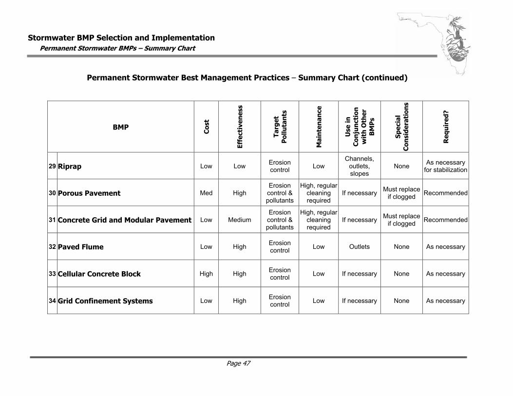
Permanent Stormwater Best Management Practices – Summary Chart (continued)
BMP
Cos
t
Effe
ctiv
enes
s
Targ
et
Pol
luta
nts
Mai
nte
nan
ce
Use
in
Con
jun
ctio
n
wit
h O
ther
B
MP
s
Spec
ial
Con
side
rati
ons
Req
uir
ed?
29 Riprap Low Low Erosion control Low
Channels, outlets, slopes
None As necessary for stabilization
30 Porous Pavement Med High Erosion control & pollutants
High, regular cleaning required
If necessary Must replace if clogged Recommended
31 Concrete Grid and Modular Pavement Low Medium Erosion control & pollutants
High, regular cleaning required
If necessary Must replace if clogged Recommended
32 Paved Flume Low High Erosion control Low Outlets None As necessary
33 Cellular Concrete Block High High Erosion control Low If necessary None As necessary
34 Grid Confinement Systems Low High Erosion control Low If necessary None As necessary
Stormwater BMP Selection and Implementation
Permanent Stormwater BMPs – Summary Chart
Page 48
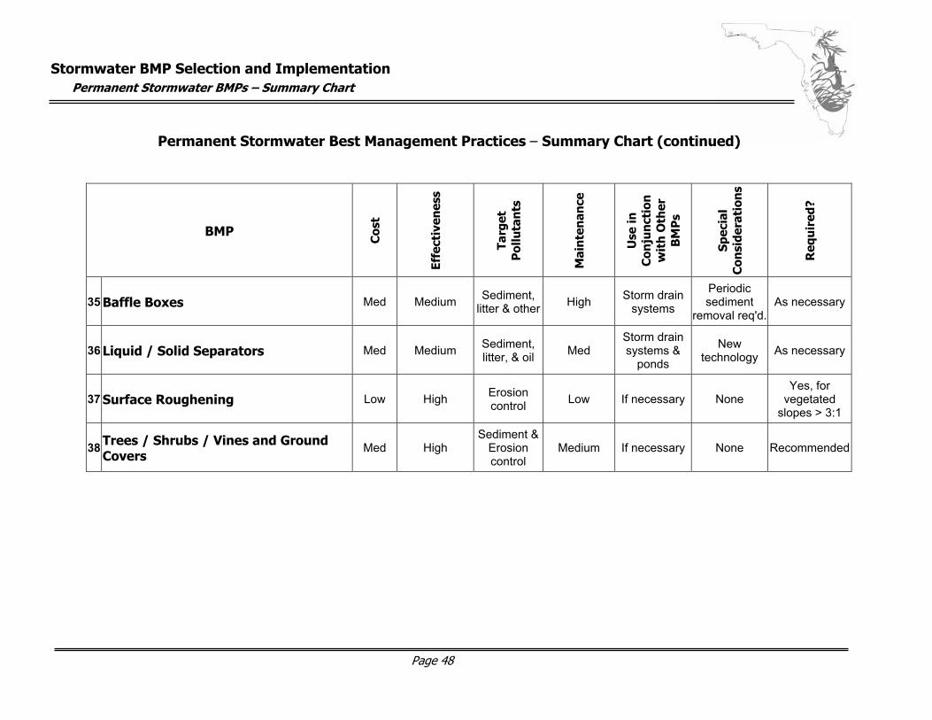
Permanent Stormwater Best Management Practices – Summary Chart (continued)
BMP
Cos
t
Effe
ctiv
enes
s
Targ
et
Pol
luta
nts
Mai
nte
nan
ce
Use
in
Con
jun
ctio
n
wit
h O
ther
B
MP
s
Spec
ial
Con
side
rati
ons
Req
uir
ed?
35 Baffle Boxes Med Medium Sediment, litter & other High Storm drain
systems
Periodic sediment
removal req'd.As necessary
36 Liquid / Solid Separators Med Medium Sediment, litter, & oil Med
Storm drain systems &
ponds
New technology As necessary
37 Surface Roughening Low High Erosion control Low If necessary None
Yes, for vegetated
slopes > 3:1
38 Trees / Shrubs / Vines and Ground Covers
Med High Sediment &
Erosion control
Medium If necessary None Recommended
Stormwater BMP Selection and Implementation
Permanent Stormwater BMPs
Page 49
Permanent Stormwater Best Management Practices – Details Permanent stormwater BMPs are necessary to meet the Florida requirements for newly developed areas to maintain runoff characteristics prior to development. With proper planning and design these BMPs can become an aesthetically integral piece of the development in addition to providing necessary water quality controls.
As discussed in Introduction, BMPs should be combined together to make up a “BMP treatment train”. This term describes a stormwater management system in which the individual BMPs are the cars making up the train – the more BMPs incorporated into the system, the better the performance of the treatment train. The “Use in Conjunction With” column of the summary chart on the previous chart will aid in determining the best treatment train for a permanent stormwater system.
17 Wet Detention Basins
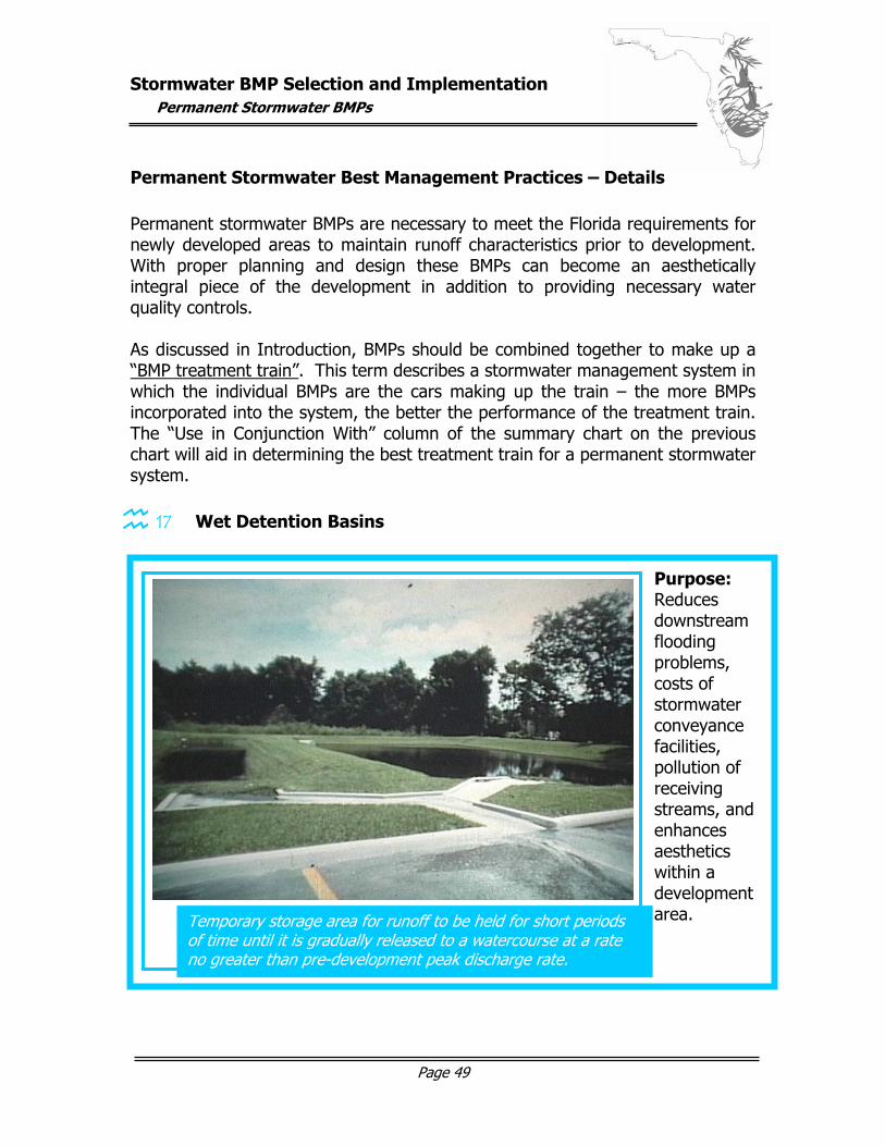
Temporary storage area for runoff to be held for short periods of time until it is gradually released to a watercourse at a rate no greater than pre-development peak discharge rate.
Purpose: Reduces downstream flooding problems, costs of stormwater conveyance facilities, pollution of receiving streams, and enhances aesthetics within a development area.
graphic here…
Stormwater BMP Selection and Implementation
Permanent Stormwater BMPs
Page 50
Wet detention basins are used in areas that will not allow the complete infiltration of water into the soil (ex. areas with slowly percolating soils and/or high water tables). In these locales wet detention basins hold stormwater runoff in addition to permanent levels of water.
Planning and Design Considerations
All detention basins must be designed in accordance with Florida DEP or Water Management District guidelines and any structural elements must be deigned by a registered Florida professional engineer. The site for a detention basin should be chosen to provide aesthetic benefits in addition to meeting technical requirements. Properly planned and constructed detention basins can provide recreation areas, wildlife habitats, water for irrigation and fire protection, and can even improve property values. A detention basin consists of a permanent water pool, an overlying zone (where runoff increases the depth while stored and then released at allowable discharge rate), and a shallow littoral zone where wetland plants biologically remove stormwater pollutants such as metals and nutrients. In this manner the water in the permanent pool is “treated” so when stormwater runoff displaces it, the clean water is that which is discharged or, in the case of a severe storm, the polluted runoff will at least be diluted. A detention basin should have a maximum depth of six feet, which will minimize recycling of pollutants stored in the bottom mud. In addition to established technical requirements, detention systems should be creatively designed to maximize aesthetics, safety, and usability while minimizing maintenance. Detention systems can be designed for regional areas to serve several projects within a watershed and can range from natural and wild to sophisticated and refined. Maintenance Considerations The highest cost associated with detention basin maintenance is sediment removal. A removal indicator should be in place to indicate when sediment reaches ten percent of the basins capacity. Care must be taken with sediment that may have high pollutant levels for proper disposal. Proper vehicle access should be provided, a method for draining the permanent pool should be included, and, ideally, an appropriate on-site sediment disposal site should be considered.

Stormwater BMP Selection and Implementation
Permanent Stormwater BMPs
Page 51
Other maintenance will include routine mowing (typically monthly in the wet season and bimonthly in the dry season), weed control, erosion repair, debris removal, etc. This can be made easier with slopes of 3:1 or less for easy access, trash racks at principal intakes, and construction of the principal spillway to resist failure from corrosion or deterioration for its design life.
Stormwater BMP Selection and Implementation
Permanent Stormwater BMPs
Page 52
18 Retention/Infiltration Basins
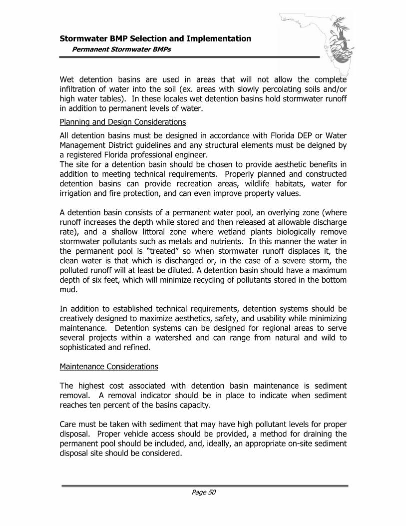
Retention basins can provide total control of urban pollutants in surface runoff for a design runoff volume. They are very effective for removing fine sediment and pollutants such as trace metals, nutrients, bacteria, and oxygen-demanding substances. Planning and Design Considerations Coarse sediment should be removed from the runoff before it enters the retention basin to avoid clogging and taking up storage volume. Detention basins, vegetative filters, oil/grit separators, or floatable skimmers may be used to remove settled solids, floating materials, and grease before it reaches the retention system. A site sensitivity analysis should be performed to identify risks of contaminating ground water from the effects of the retention basin.
Water impoundment constructed over permeable soils to temporarily store surface runoff and allow it to infiltrate through the bottom and sides of the basin.
Purpose: Removes many pollutants, provides ground water recharge, reduces the volume of runoff and reduces peak discharges.
graphic here…
Stormwater BMP Selection and Implementation
Permanent Stormwater BMPs
Page 53
The most limiting factor in retention basin design is enough available space to allow the retention basin to handle (via percolation and/or evaporation) all runoff to allow for upcoming storm events and to insure viability of vegetation. Soils in the basin area should be permit infiltration rates of at least three to five inches an hour. Retention basin design must be in accordance with Florida DEP or Water Management District guidelines and a Florida registered professional engineer must design all structural components. Maintenance Considerations Basins should be inspected at least semiannually and after major storms. When sediment is dry enough so it cracks and readily separates from the basin floor it should be removed. Vegetation should be chosen appropriate for site conditions. Maintaining vegetation (by mowing, fertilizing, etc.) will help control weed growth.
Stormwater BMP Selection and Implementation
Permanent Stormwater BMPs
Page 54
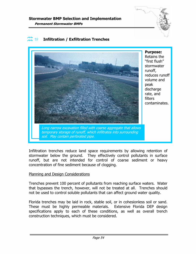
19 Infiltration / Exfiltration Trenches
Infiltration trenches reduce land space requirements by allowing retention of stormwater below the ground. They effectively control pollutants in surface runoff, but are not intended for control of coarse sediment or heavy concentration of fine sediment because of clogging. Planning and Design Considerations Trenches prevent 100 percent of pollutants from reaching surface waters. Water that bypasses the trench, however, will not be treated at all. Trenches should not be used to control soluble pollutants that can affect ground water quality. Florida trenches may be laid in rock, stable soil, or in cohesionless soil or sand. These must be highly permeable materials. Extensive Florida DEP design specifications apply to each of these conditions, as well as overall trench construction techniques, which must be considered.
Long narrow excavation filled with coarse aggregate that allows temporary storage of runoff, which infiltrates into surrounding soil. May contain perforated pipe.
Purpose: Retains the “first flush” stormwater runoff, reduces runoff volume and peak discharge rate, and filters contaminates.
graphic here…
Stormwater BMP Selection and Implementation
Permanent Stormwater BMPs
Page 55
Trenches range from three to twelve feet in depth depending on stormwater volume, soil and water table conditions with their bottoms at least four feet about the seasonal high water table. Surface trenches receive runoff directly from adjacent areas, preferably after it has been filtered by a 20 foot grassed strip. They are accessible for maintenance and can be used in highway medians, parking lots and in narrow landscaped areas. The lifespan of an infiltration trench is approximately two to three years. Underground trenches accept runoff from storm sewers with adequate pretreatment measures in place. They usually consist of an oversized perforated pipe within the aggregate envelope. Two to three foot sumps should be placed at all inlets and removable skimmers placed over pipe entrances to minimize dirt and trash entering the system. As most exfiltration systems will require periodic complete replacement, they should not be placed under pavement. Maintenance Considerations Great care should be taken to eliminate or greatly reduce clogging of infiltration / exfiltration trenches. Rehabilitation can be expensive. It is critical to get responsible property owners involved in trench monitoring and make sure they are aware of the trench function. Inspection should be performed at least on a semiannual basis. This should include checking for water ponding, recording of water levels over a several day period, and physically viewing the filtering system. Routine maintenance should include vacuuming debris from catch basin inlets (for underground trenches) and filter systems when no more than ten percent of their capacity has been depleted.
Stormwater BMP Selection and Implementation
Permanent Stormwater BMPs
Page 56
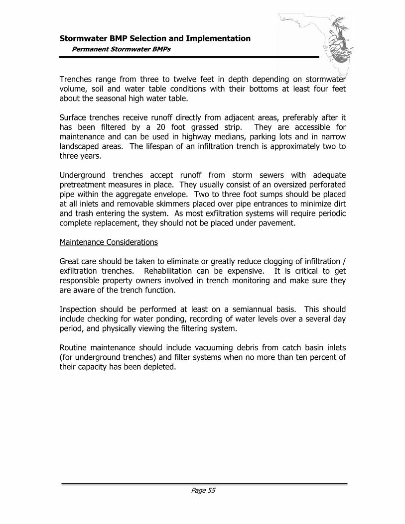
20 Grassed Waterways & Swales
Grassed swales are most effective for the removal of coarse sediment and associated pollutants. They will contain standing or flowing water only after a rainfall. Planning and Design Considerations Unless designed to percolate 80 percent of the runoff from a three-inch rainfall within 72 hours, they act mostly as a conveyance system that reduces pollutants to retention basin, detention basin or wetland. Swales are generally less expensive to install than curbs and gutters and are effective at keeping flow away from street surfaces during storms. The are less feasible in areas with l large number of driveway entrances. Swales should have side slopes of 3:1 or flatter, and should be planted with vegetation suitable for soil stabilization, stormwater treatment, and nutrient uptake. They should also have a top width to depth ration that is at least 6:1.
Broad shallow channels with dense stand of vegetation established in them.
Purpose: Uses low velocities and vegetative cover to settle pollutants and provide infiltration. Can also result in reduced volumes of runoff and peak discharges.
graphic here…
Stormwater BMP Selection and Implementation
Permanent Stormwater BMPs
Page 57
Small check dams may be incorporated into the swale design to slow runoff and allow more time for infiltration. Swale design should be in accordance with Florida DEP and Water Management District guidelines. Maintenance Considerations Maintenance of grassed swales should not be much greater than that for normal lawns. This should include adequate mowing and fertilization. Care should be taken not to fill the swale with leaves, vegetation, or other debris. No vehicular traffic should be permitted in the swale area.
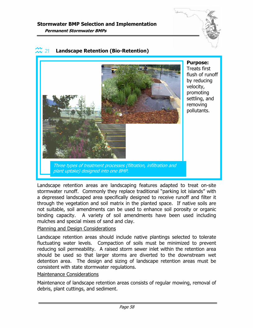
Stormwater BMP Selection and Implementation
Permanent Stormwater BMPs
Page 58
21 Landscape Retention (Bio-Retention)
Landscape retention areas are landscaping features adapted to treat on-site stormwater runoff. Commonly they replace traditional “parking lot islands” with a depressed landscaped area specifically designed to receive runoff and filter it through the vegetation and soil matrix in the planted space. If native soils are not suitable, soil amendments can be used to enhance soil porosity or organic binding capacity. A variety of soil amendments have been used including mulches and special mixes of sand and clay. Planning and Design Considerations
Landscape retention areas should include native plantings selected to tolerate fluctuating water levels. Compaction of soils must be minimized to prevent reducing soil permeability. A raised storm sewer inlet within the retention area should be used so that larger storms are diverted to the downstream wet detention area. The design and sizing of landscape retention areas must be consistent with state stormwater regulations. Maintenance Considerations
Maintenance of landscape retention areas consists of regular mowing, removal of debris, plant cuttings, and sediment.
Three types of treatment processes (filtration, infiltration and plant uptake) designed into one BMP.
Purpose: Treats first flush of runoff by reducing velocity, promoting settling, and removing pollutants.
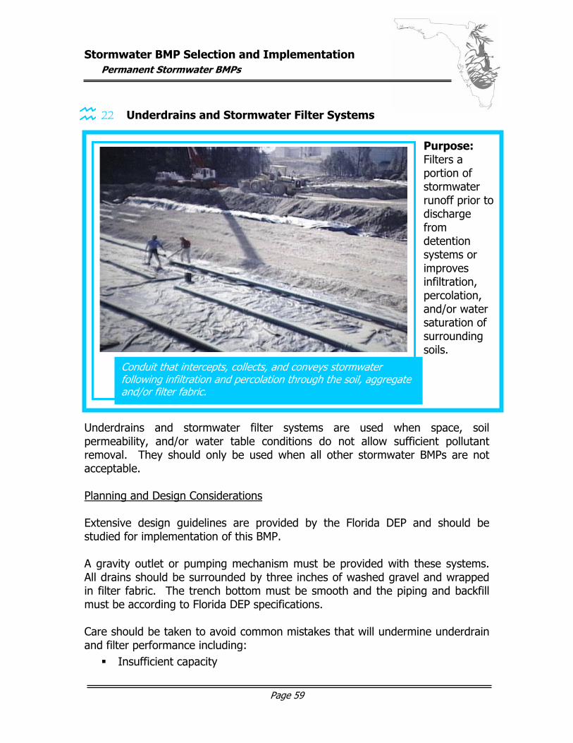
Stormwater BMP Selection and Implementation
Permanent Stormwater BMPs
Page 59
22 Underdrains and Stormwater Filter Systems
Underdrains and stormwater filter systems are used when space, soil permeability, and/or water table conditions do not allow sufficient pollutant removal. They should only be used when all other stormwater BMPs are not acceptable. Planning and Design Considerations Extensive design guidelines are provided by the Florida DEP and should be studied for implementation of this BMP. A gravity outlet or pumping mechanism must be provided with these systems. All drains should be surrounded by three inches of washed gravel and wrapped in filter fabric. The trench bottom must be smooth and the piping and backfill must be according to Florida DEP specifications. Care should be taken to avoid common mistakes that will undermine underdrain and filter performance including: Insufficient capacity
Conduit that intercepts, collects, and conveys stormwater following infiltration and percolation through the soil, aggregate and/or filter fabric.
Purpose: Filters a portion of stormwater runoff prior to discharge from detention systems or improves infiltration, percolation, and/or water saturation of surrounding soils.
graphic here…
Stormwater BMP Selection and Implementation
Permanent Stormwater BMPs
Page 60
Shallow placement with lack of auxiliary structures Insufficient strength Poor construction such as poor joint connections, fittings, bedding, grade,
alignment, backfilling Inadequate handling of mineral deposits
Maintenance Considerations Filter systems must be routinely inspected and regularly cleaned/repaired/replaced as necessary to insure continued optimum performance.
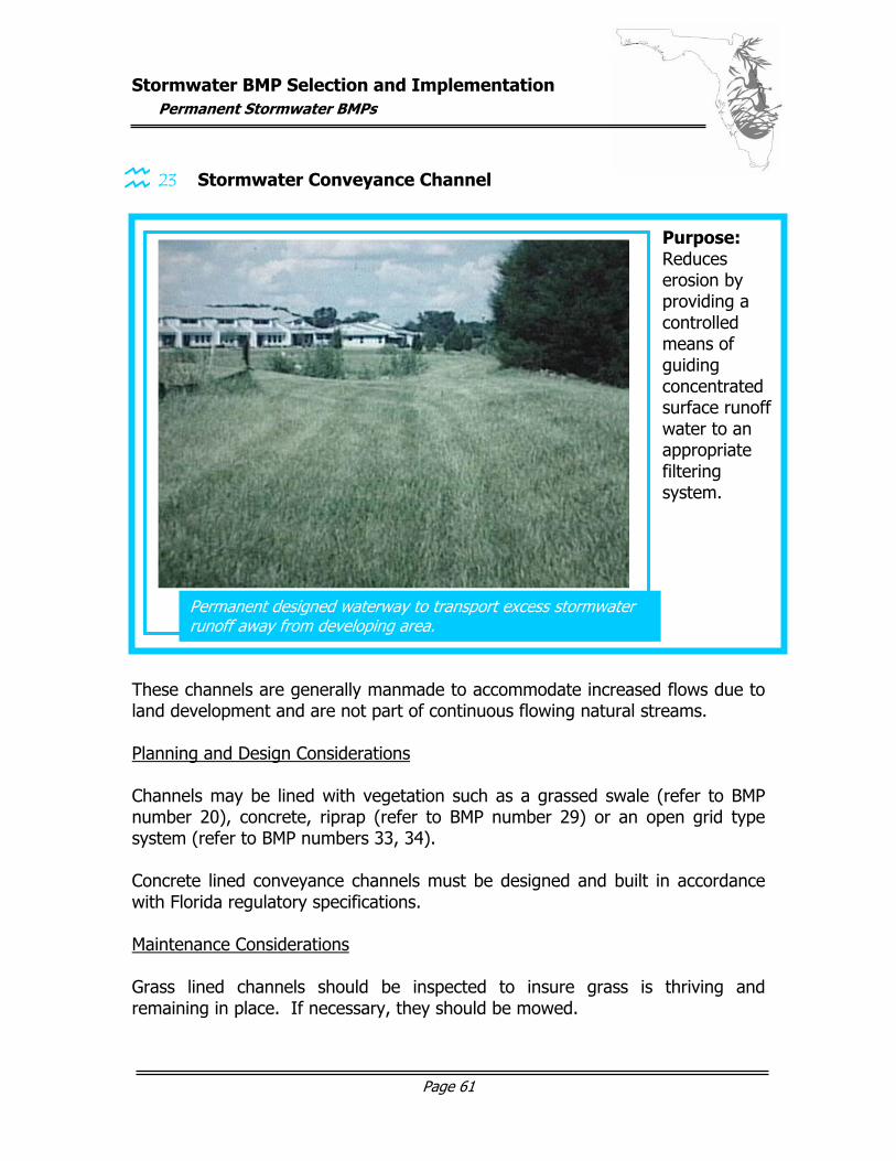
Stormwater BMP Selection and Implementation
Permanent Stormwater BMPs
Page 61
23 Stormwater Conveyance Channel
These channels are generally manmade to accommodate increased flows due to land development and are not part of continuous flowing natural streams. Planning and Design Considerations Channels may be lined with vegetation such as a grassed swale (refer to BMP number 20), concrete, riprap (refer to BMP number 29) or an open grid type system (refer to BMP numbers 33, 34). Concrete lined conveyance channels must be designed and built in accordance with Florida regulatory specifications. Maintenance Considerations Grass lined channels should be inspected to insure grass is thriving and remaining in place. If necessary, they should be mowed.
Permanent designed waterway to transport excess stormwater runoff away from developing area.
Purpose: Reduces erosion by providing a controlled means of guiding concentrated surface runoff water to an appropriate filtering system.
graphic here…
Stormwater BMP Selection and Implementation
Permanent Stormwater BMPs
Page 62
Concrete channels should be inspected to insure there is no undermining of the channel, particularly at the outlet. Open grid type / flexible liner channels should be inspected to insure the blocks remain in place. If necessary, they should be mowed and large weeds should be controlled.
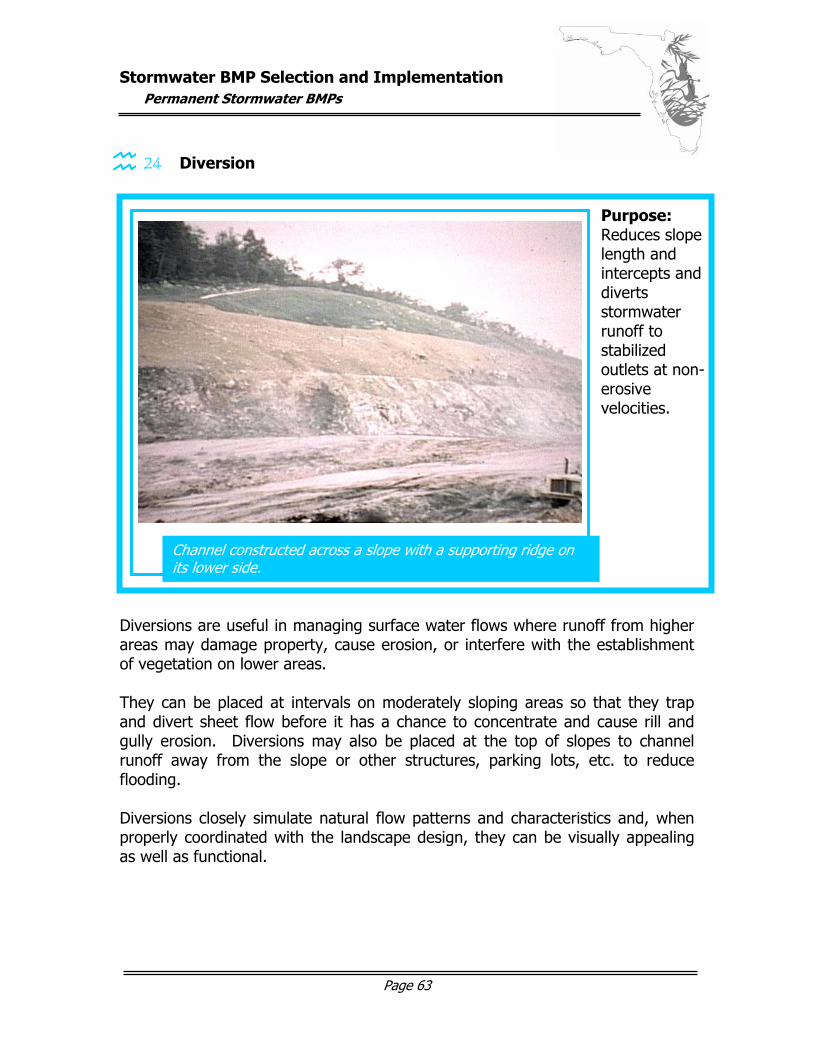
Stormwater BMP Selection and Implementation
Permanent Stormwater BMPs
Page 63
24 Diversion
Diversions are useful in managing surface water flows where runoff from higher areas may damage property, cause erosion, or interfere with the establishment of vegetation on lower areas. They can be placed at intervals on moderately sloping areas so that they trap and divert sheet flow before it has a chance to concentrate and cause rill and gully erosion. Diversions may also be placed at the top of slopes to channel runoff away from the slope or other structures, parking lots, etc. to reduce flooding. Diversions closely simulate natural flow patterns and characteristics and, when properly coordinated with the landscape design, they can be visually appealing as well as functional.
Channel constructed across a slope with a supporting ridge on its lower side.
Purpose: Reduces slope length and intercepts and diverts stormwater runoff to stabilized outlets at non-erosive velocities.
graphic here…
Stormwater BMP Selection and Implementation
Permanent Stormwater BMPs
Page 64
Planning and Design Considerations Diversion channels must have a minimum capacity to carry the runoff expected from a ten-year frequency storm. The shape of the channel may be parabolic, trapezoidal, or v-shaped and should be constructed in accordance with Florida DEP guidelines. The supporting ridge should have side slopes no steeper than 2:1, width at the design water elevation of at least four feet, a freeboard of at least 0.3 foot, and should be based on a ten percent settlement factor. Maintenance Considerations Vegetation should be established, both in the channel and on the supporting ridge, as soon as possible and stabilized at least within 15 days of installation. Inspection, reseeding, mowing and fertilizing should be performed as necessary to maintain the diversion characteristics.
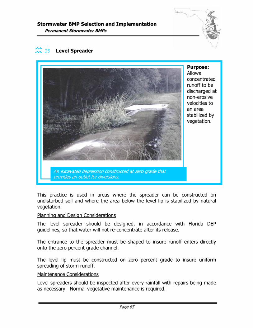
Stormwater BMP Selection and Implementation
Permanent Stormwater BMPs
Page 65
25 Level Spreader
This practice is used in areas where the spreader can be constructed on undisturbed soil and where the area below the level lip is stabilized by natural vegetation.
Planning and Design Considerations
The level spreader should be designed, in accordance with Florida DEP guidelines, so that water will not re-concentrate after its release. The entrance to the spreader must be shaped to insure runoff enters directly onto the zero percent grade channel. The level lip must be constructed on zero percent grade to insure uniform spreading of storm runoff.
Maintenance Considerations
Level spreaders should be inspected after every rainfall with repairs being made as necessary. Normal vegetative maintenance is required.
An excavated depression constructed at zero grade that provides an outlet for diversions.
Purpose: Allows concentrated runoff to be discharged at non-erosive velocities to an area stabilized by vegetation.
graphic here…
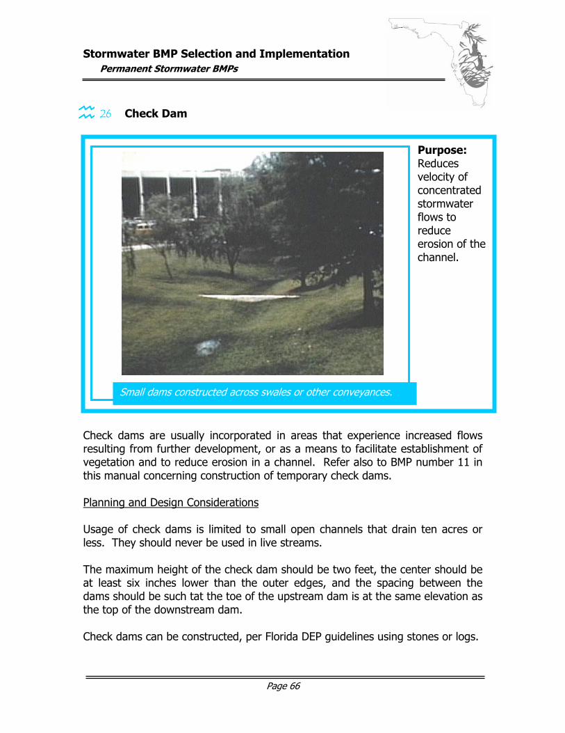
Stormwater BMP Selection and Implementation
Permanent Stormwater BMPs
Page 66
26 Check Dam
Check dams are usually incorporated in areas that experience increased flows resulting from further development, or as a means to facilitate establishment of vegetation and to reduce erosion in a channel. Refer also to BMP number 11 in this manual concerning construction of temporary check dams. Planning and Design Considerations Usage of check dams is limited to small open channels that drain ten acres or less. They should never be used in live streams. The maximum height of the check dam should be two feet, the center should be at least six inches lower than the outer edges, and the spacing between the dams should be such tat the toe of the upstream dam is at the same elevation as the top of the downstream dam. Check dams can be constructed, per Florida DEP guidelines using stones or logs.
Small dams constructed across swales or other conveyances.
Purpose: Reduces velocity of concentrated stormwater flows to reduce erosion of the channel.
graphic here…

Stormwater BMP Selection and Implementation
Permanent Stormwater BMPs
Page 67
Maintenance Considerations Check dams should be inspected to insure the height of the dam remains lower than at the center than the edges. They should be inspected for accumulation of sediment, which should be removed when it reaches one-fourth of the dam height. Erosion around the edges of the dam should also be monitored.
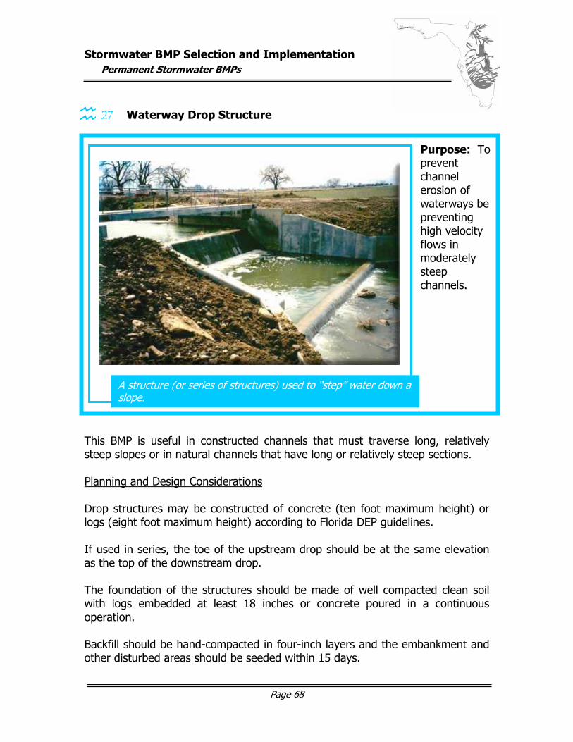
Stormwater BMP Selection and Implementation
Permanent Stormwater BMPs
Page 68
27 Waterway Drop Structure
This BMP is useful in constructed channels that must traverse long, relatively steep slopes or in natural channels that have long or relatively steep sections. Planning and Design Considerations Drop structures may be constructed of concrete (ten foot maximum height) or logs (eight foot maximum height) according to Florida DEP guidelines. If used in series, the toe of the upstream drop should be at the same elevation as the top of the downstream drop. The foundation of the structures should be made of well compacted clean soil with logs embedded at least 18 inches or concrete poured in a continuous operation. Backfill should be hand-compacted in four-inch layers and the embankment and other disturbed areas should be seeded within 15 days.
A structure (or series of structures) used to “step” water down a slope.
Purpose: To prevent channel erosion of waterways be preventing high velocity flows in moderately steep channels.
Stormwater BMP Selection and Implementation
Permanent Stormwater BMPs
Page 69
Maintenance Considerations Waterway drop structures should be inspected to insure there is no scour above and below the structure and to insure the drop remains structurally sound. The embankment vegetation should be inspected to insure that it remains well established.
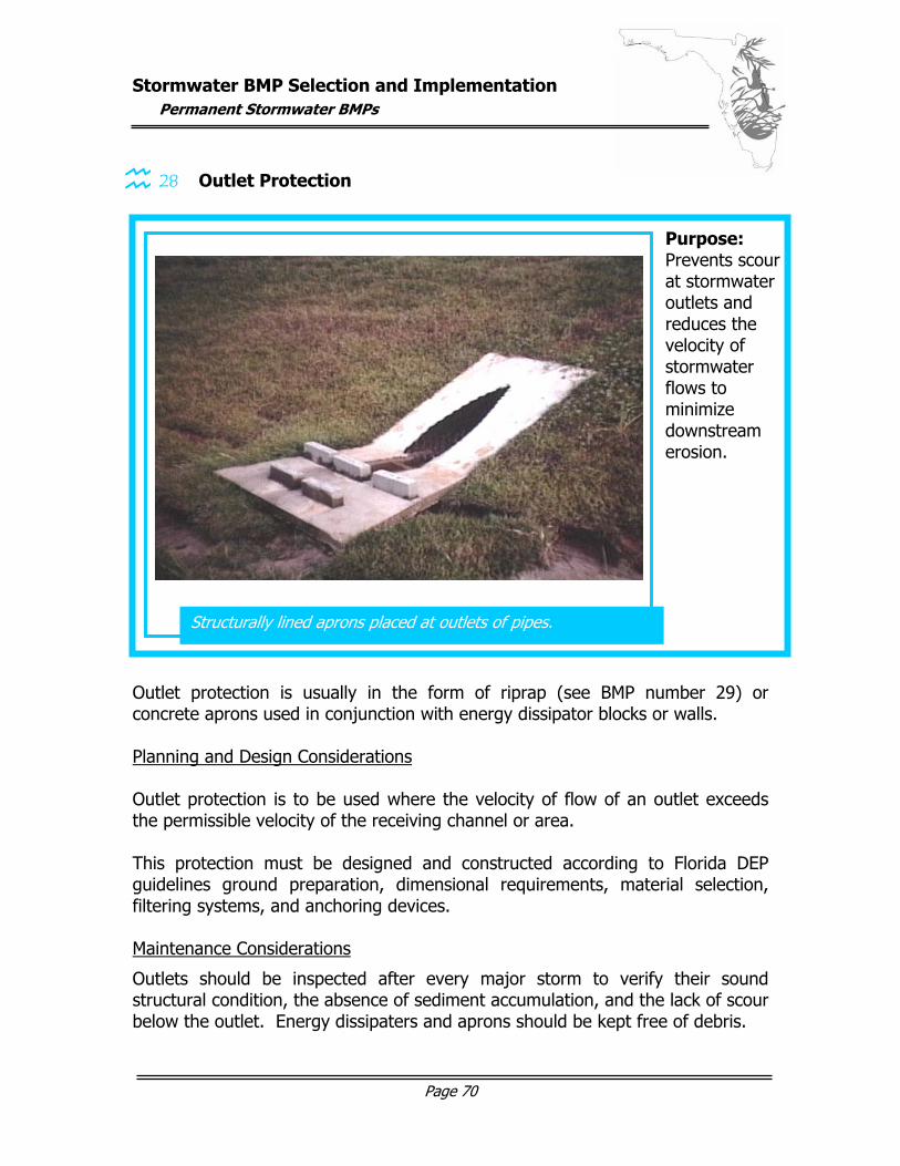
Stormwater BMP Selection and Implementation
Permanent Stormwater BMPs
Page 70
28 Outlet Protection
Outlet protection is usually in the form of riprap (see BMP number 29) or concrete aprons used in conjunction with energy dissipator blocks or walls. Planning and Design Considerations Outlet protection is to be used where the velocity of flow of an outlet exceeds the permissible velocity of the receiving channel or area. This protection must be designed and constructed according to Florida DEP guidelines ground preparation, dimensional requirements, material selection, filtering systems, and anchoring devices. Maintenance Considerations
Outlets should be inspected after every major storm to verify their sound structural condition, the absence of sediment accumulation, and the lack of scour below the outlet. Energy dissipaters and aprons should be kept free of debris.
Structurally lined aprons placed at outlets of pipes.
Purpose: Prevents scour at stormwater outlets and reduces the velocity of stormwater flows to minimize downstream erosion.
graphic here…
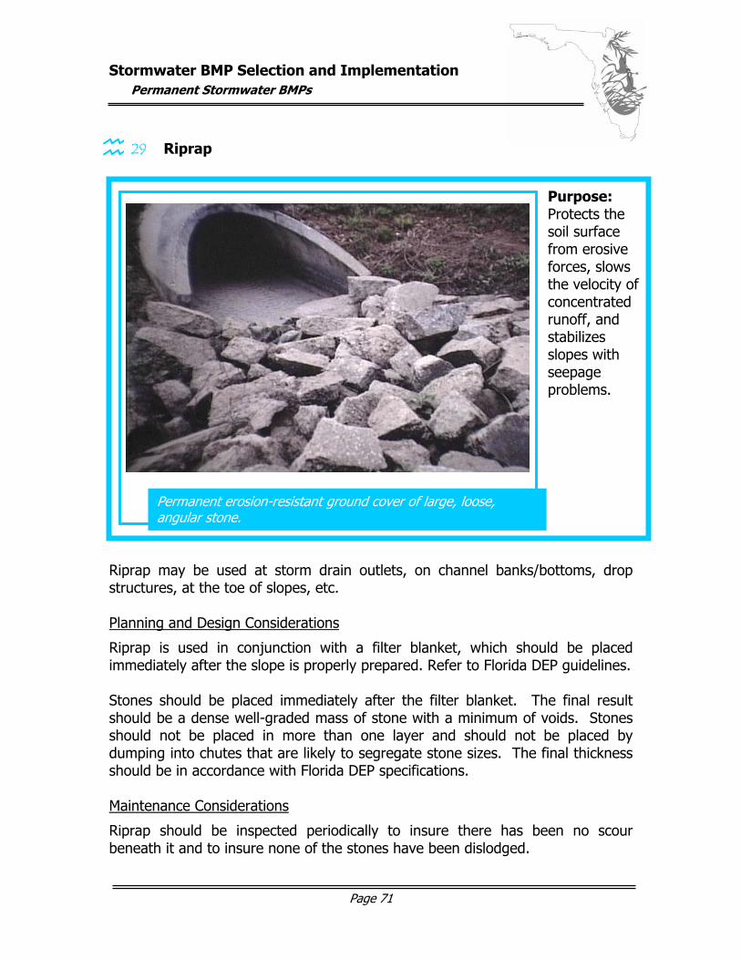
Stormwater BMP Selection and Implementation
Permanent Stormwater BMPs
Page 71
29 Riprap
Riprap may be used at storm drain outlets, on channel banks/bottoms, drop structures, at the toe of slopes, etc. Planning and Design Considerations
Riprap is used in conjunction with a filter blanket, which should be placed immediately after the slope is properly prepared. Refer to Florida DEP guidelines. Stones should be placed immediately after the filter blanket. The final result should be a dense well-graded mass of stone with a minimum of voids. Stones should not be placed in more than one layer and should not be placed by dumping into chutes that are likely to segregate stone sizes. The final thickness should be in accordance with Florida DEP specifications. Maintenance Considerations
Riprap should be inspected periodically to insure there has been no scour beneath it and to insure none of the stones have been dislodged.
Permanent erosion-resistant ground cover of large, loose, angular stone.
Purpose: Protects the soil surface from erosive forces, slows the velocity of concentrated runoff, and stabilizes slopes with seepage problems.
graphic here…
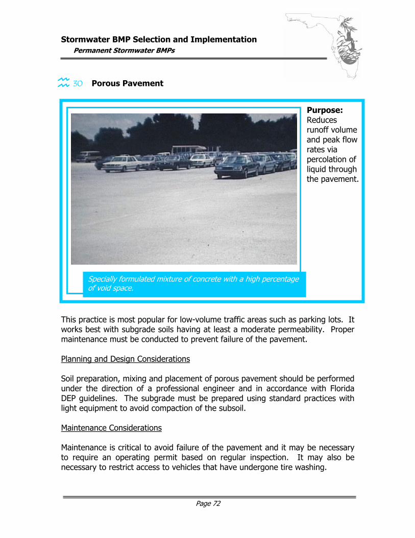
Stormwater BMP Selection and Implementation
Permanent Stormwater BMPs
Page 72
30 Porous Pavement
This practice is most popular for low-volume traffic areas such as parking lots. It works best with subgrade soils having at least a moderate permeability. Proper maintenance must be conducted to prevent failure of the pavement. Planning and Design Considerations Soil preparation, mixing and placement of porous pavement should be performed under the direction of a professional engineer and in accordance with Florida DEP guidelines. The subgrade must be prepared using standard practices with light equipment to avoid compaction of the subsoil. Maintenance Considerations Maintenance is critical to avoid failure of the pavement and it may be necessary to require an operating permit based on regular inspection. It may also be necessary to restrict access to vehicles that have undergone tire washing.
Specially formulated mixture of concrete with a high percentage of void space.
Purpose: Reduces runoff volume and peak flow rates via percolation of liquid through the pavement.
graphic here…
Stormwater BMP Selection and Implementation
Permanent Stormwater BMPs
Page 73
Debris should be removed on a regular basis and it is necessary to actually vacuum the pavement to remove particulates that are too large to pass through its void spaces. Vacuum cleaning alone is ineffective and must be followed by high-pressure water washing of the pavement. A monthly cleaning with a street sweeper is required. Porous pavement should be routinely inspected to identify clogging. If ponding or clogging is noticed a street sweeper with a vacuum should be used. If necessary, this should be followed by steam cleaning with a biodegradable substance then re-vacuumed. If a large area of the pavement is clogged and cannot be adequately cleaned, the paving must be removed and then filled in with new porous pavement. It may be necessary to also remove and replace some amount of the subgrade.
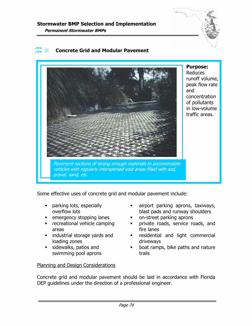
Stormwater BMP Selection and Implementation
Permanent Stormwater BMPs
Page 74
31 Concrete Grid and Modular Pavement
Some effective uses of concrete grid and modular pavement include:
parking lots, especially overflow lots
airport parking aprons, taxiways, blast pads and runway shoulders
emergency stopping lanes on-street parking aprons recreational vehicle camping
areas private roads, service roads, and
fire lanes industrial storage yards and
loading zones residential and light commercial
driveways sidewalks, patios and
swimming pool aprons boat ramps, bike paths and nature
trails Planning and Design Considerations Concrete grid and modular pavement should be laid in accordance with Florida DEP guidelines under the direction of a professional engineer.
Pavement sections of strong enough materials to accommodate vehicles with regularly interspersed void areas filled with sod, gravel, sand, etc.
Purpose: Reduces runoff volume, peak flow rate and concentration of pollutants in low-volume traffic areas.
graphic here…

Stormwater BMP Selection and Implementation
Permanent Stormwater BMPs
Page 75
Light equipment should be used to avoid compaction of the subsoil. The void spaces can be filled with sand, gravel or vegetation. Maintenance Considerations When turf is incorporated into the grid system, regular vegetative maintenance is required. However, mowing is seldom necessary where frequent vehicular traffic is present. Fertilizers, pesticides and other chemicals may have adverse effects on these concrete products and should be used as little as possible.
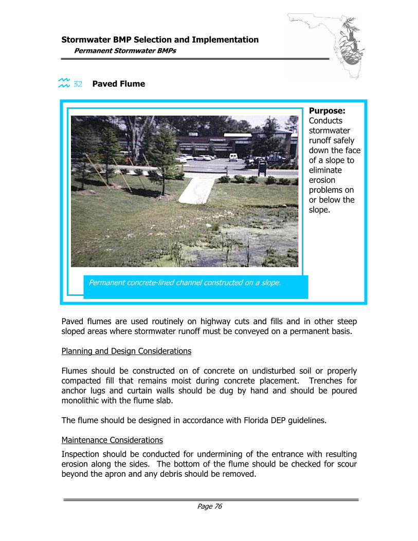
Stormwater BMP Selection and Implementation
Permanent Stormwater BMPs
Page 76
32 Paved Flume
Paved flumes are used routinely on highway cuts and fills and in other steep sloped areas where stormwater runoff must be conveyed on a permanent basis. Planning and Design Considerations Flumes should be constructed on of concrete on undisturbed soil or properly compacted fill that remains moist during concrete placement. Trenches for anchor lugs and curtain walls should be dug by hand and should be poured monolithic with the flume slab. The flume should be designed in accordance with Florida DEP guidelines. Maintenance Considerations
Inspection should be conducted for undermining of the entrance with resulting erosion along the sides. The bottom of the flume should be checked for scour beyond the apron and any debris should be removed.
Permanent concrete-lined channel constructed on a slope.
Purpose: Conducts stormwater runoff safely down the face of a slope to eliminate erosion problems on or below the slope.
graphic here…
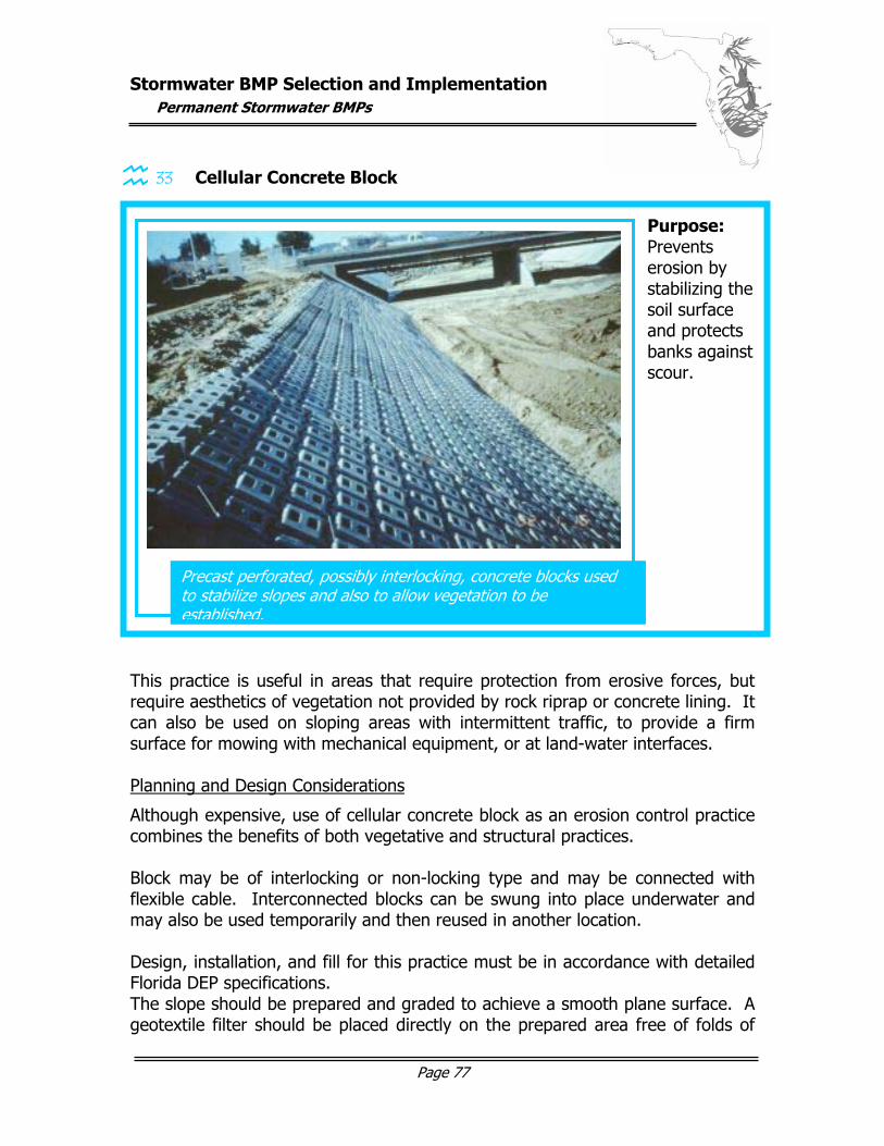
Stormwater BMP Selection and Implementation
Permanent Stormwater BMPs
Page 77
33 Cellular Concrete Block
This practice is useful in areas that require protection from erosive forces, but require aesthetics of vegetation not provided by rock riprap or concrete lining. It can also be used on sloping areas with intermittent traffic, to provide a firm surface for mowing with mechanical equipment, or at land-water interfaces. Planning and Design Considerations
Although expensive, use of cellular concrete block as an erosion control practice combines the benefits of both vegetative and structural practices. Block may be of interlocking or non-locking type and may be connected with flexible cable. Interconnected blocks can be swung into place underwater and may also be used temporarily and then reused in another location. Design, installation, and fill for this practice must be in accordance with detailed Florida DEP specifications. The slope should be prepared and graded to achieve a smooth plane surface. A geotextile filter should be placed directly on the prepared area free of folds of
Precast perforated, possibly interlocking, concrete blocks used to stabilize slopes and also to allow vegetation to be established.
Purpose: Prevents erosion by stabilizing the soil surface and protects banks against scour.
Stormwater BMP Selection and Implementation
Permanent Stormwater BMPs
Page 78
wrinkles. The block should be placed to produce a smooth plane surface that is intimate contact with the filter fabric with no individual block protruding more than ½ an inch. Distinct grade changes should be accommodated with a transition curve of at least four feet. Grouting can be placed at sharp bends, pipe outlets, intersections or other irregular areas. Below waterlines void spaces should be filled with gravel and above waterlines they should be filled with soil and appropriate seeded vegetation. Maintenance Considerations
Inspection should be conducted on a routine basis to identify any undermining of the system. Any large vegetation should be controlled so roots do not cause failure of the system.
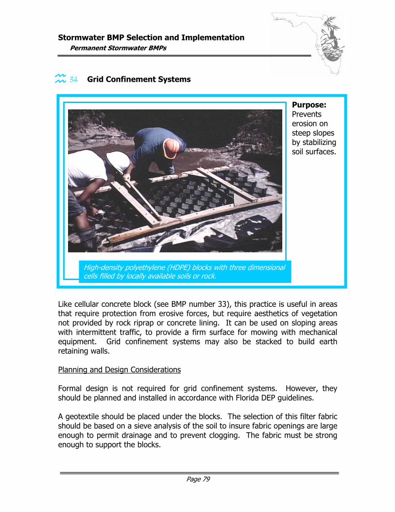
Stormwater BMP Selection and Implementation
Permanent Stormwater BMPs
Page 79
34 Grid Confinement Systems
Like cellular concrete block (see BMP number 33), this practice is useful in areas that require protection from erosive forces, but require aesthetics of vegetation not provided by rock riprap or concrete lining. It can be used on sloping areas with intermittent traffic, to provide a firm surface for mowing with mechanical equipment. Grid confinement systems may also be stacked to build earth retaining walls. Planning and Design Considerations Formal design is not required for grid confinement systems. However, they should be planned and installed in accordance with Florida DEP guidelines. A geotextile should be placed under the blocks. The selection of this filter fabric should be based on a sieve analysis of the soil to insure fabric openings are large enough to permit drainage and to prevent clogging. The fabric must be strong enough to support the blocks.
High-density polyethylene (HDPE) blocks with three dimensional cells filled by locally available soils or rock.
Purpose: Prevents erosion on steep slopes by stabilizing soil surfaces. graphic here…
Stormwater BMP Selection and Implementation
Permanent Stormwater BMPs
Page 80
Blocks should be placed on a prepared smooth plane of a slope. The blocks must be staked and locked as appropriate. The open cells should then be filled with gravel, crushed stone or soil. If soil is used, seed should be pre-mixed with the soil to accelerate establishment of vegetation. Be sure equipment is not driven over open / non-filled cells. Maintenance Considerations Inspection should be conducted on a routine basis to identify any undermining of the system. As with concrete cellular blocks, any large vegetation should be controlled so roots do not cause failure of the system.
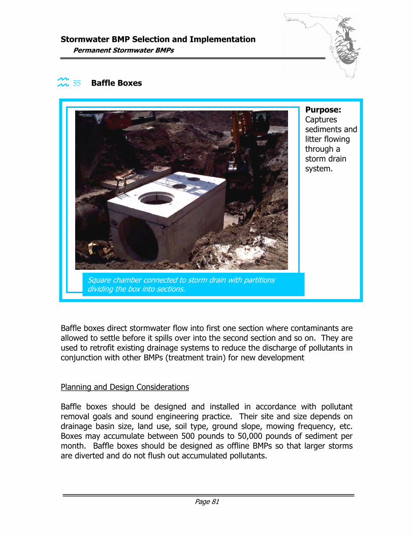
Stormwater BMP Selection and Implementation
Permanent Stormwater BMPs
Page 81
35 Baffle Boxes
Baffle boxes direct stormwater flow into first one section where contaminants are allowed to settle before it spills over into the second section and so on. They are used to retrofit existing drainage systems to reduce the discharge of pollutants in conjunction with other BMPs (treatment train) for new development Planning and Design Considerations Baffle boxes should be designed and installed in accordance with pollutant removal goals and sound engineering practice. Their site and size depends on drainage basin size, land use, soil type, ground slope, mowing frequency, etc. Boxes may accumulate between 500 pounds to 50,000 pounds of sediment per month. Baffle boxes should be designed as offline BMPs so that larger storms are diverted and do not flush out accumulated pollutants.
Square chamber connected to storm drain with partitions dividing the box into sections.
Purpose: Captures sediments and litter flowing through a storm drain system.
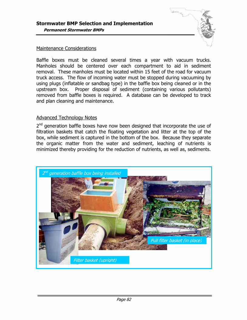
Stormwater BMP Selection and Implementation
Permanent Stormwater BMPs
Page 82
Maintenance Considerations Baffle boxes must be cleaned several times a year with vacuum trucks. Manholes should be centered over each compartment to aid in sediment removal. These manholes must be located within 15 feet of the road for vacuum truck access. The flow of incoming water must be stopped during vacuuming by using plugs (inflatable or sandbag type) in the baffle box being cleaned or in the upstream box. Proper disposal of sediment (containing various pollutants) removed from baffle boxes is required. A database can be developed to track and plan cleaning and maintenance.
Advanced Technology Notes
2nd generation baffle boxes have now been designed that incorporate the use of filtration baskets that catch the floating vegetation and litter at the top of the box, while sediment is captured in the bottom of the box. Because they separate the organic matter from the water and sediment, leaching of nutrients is minimized thereby providing for the reduction of nutrients, as well as, sediments.
2nd generation baffle box being installed
Filter basket (upright)
Full filter basket (in place)
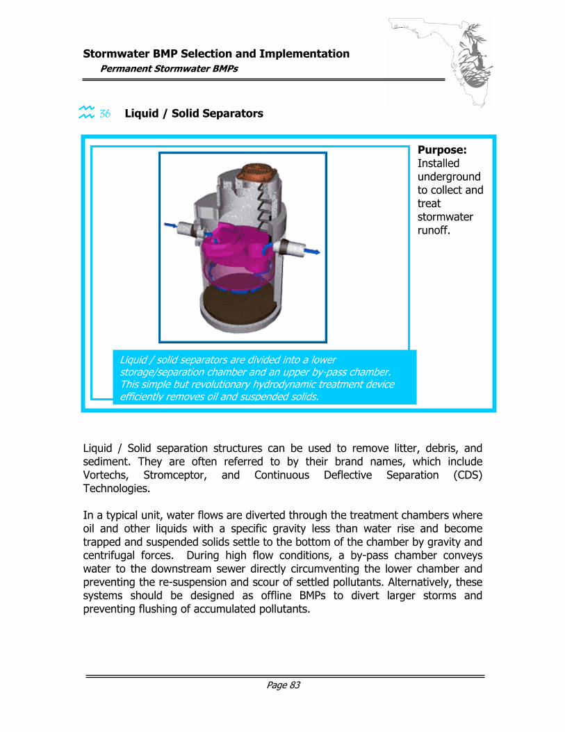
Stormwater BMP Selection and Implementation
Permanent Stormwater BMPs
Page 83
36 Liquid / Solid Separators
Liquid / Solid separation structures can be used to remove litter, debris, and sediment. They are often referred to by their brand names, which include Vortechs, Stromceptor, and Continuous Deflective Separation (CDS) Technologies. In a typical unit, water flows are diverted through the treatment chambers where oil and other liquids with a specific gravity less than water rise and become trapped and suspended solids settle to the bottom of the chamber by gravity and centrifugal forces. During high flow conditions, a by-pass chamber conveys water to the downstream sewer directly circumventing the lower chamber and preventing the re-suspension and scour of settled pollutants. Alternatively, these systems should be designed as offline BMPs to divert larger storms and preventing flushing of accumulated pollutants.
Liquid / solid separators are divided into a lower storage/separation chamber and an upper by-pass chamber. This simple but revolutionary hydrodynamic treatment device efficiently removes oil and suspended solids.
Purpose: Installed underground to collect and treat stormwater runoff.
Stormwater BMP Selection and Implementation
Permanent Stormwater BMPs
Page 84
Planning and Design Considerations Liquid / solid separators are a new technology which mainly remove litter and larger sediment particles. Accordingly, they are a useful stormwater retrofitting BMP or they can be used as a pre-treatment system before stormwater is discharged to a wet detention pond. Maintenance Considerations Liquid / solid separators were designed to be easily monitored and cleaned from the surface without requiring entry into the unit. Maintenance is performed from one access point by vacuum truck. The time between each cleaning depends on the location of the liquid / solid separator and the resulting pollutant loads. The cost of cleaning also varies depending on the size of the unit. In most cases, however, it is cheaper and as efficient in controlling runoff as traditional devices.
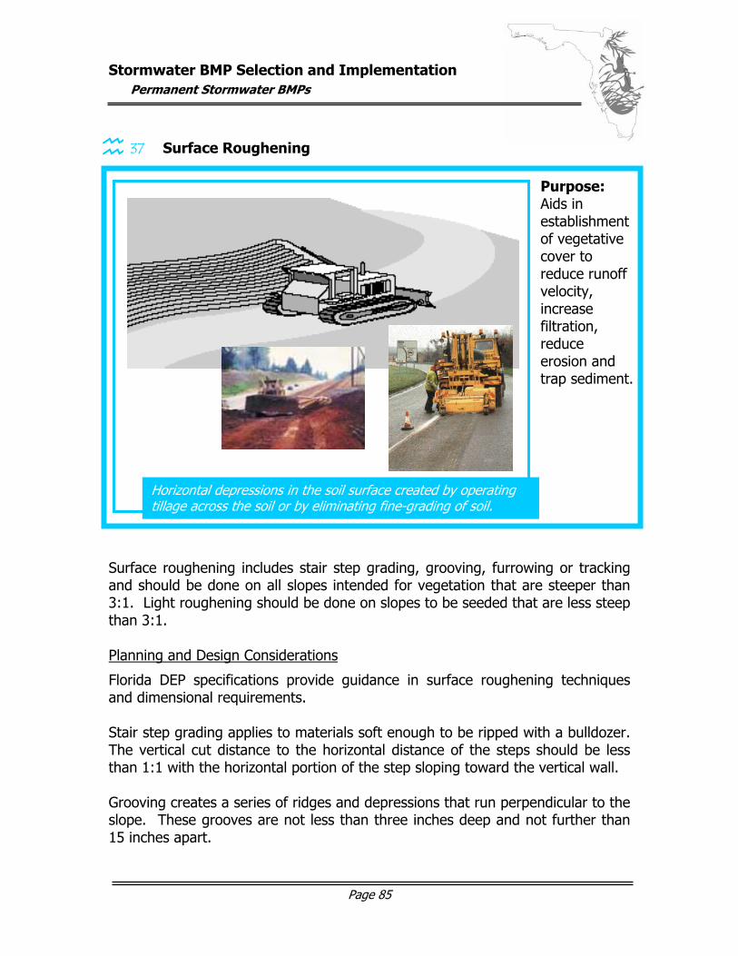
Stormwater BMP Selection and Implementation
Permanent Stormwater BMPs
Page 85
37 Surface Roughening Surface roughening includes stair step grading, grooving, furrowing or tracking and should be done on all slopes intended for vegetation that are steeper than 3:1. Light roughening should be done on slopes to be seeded that are less steep than 3:1. Planning and Design Considerations
Florida DEP specifications provide guidance in surface roughening techniques and dimensional requirements. Stair step grading applies to materials soft enough to be ripped with a bulldozer. The vertical cut distance to the horizontal distance of the steps should be less than 1:1 with the horizontal portion of the step sloping toward the vertical wall. Grooving creates a series of ridges and depressions that run perpendicular to the slope. These grooves are not less than three inches deep and not further than 15 inches apart.
Horizontal depressions in the soil surface created by operating tillage across the soil or by eliminating fine-grading of soil.
Purpose: Aids in establishment of vegetative cover to reduce runoff velocity, increase filtration, reduce erosion and trap sediment.
Stormwater BMP Selection and Implementation
Permanent Stormwater BMPs
Page 86
Furrowing / tracking may be performed on sandy soils that do not easily compact. This is done by operating tracked machinery up and down the slope to leave horizontal depressions in the soil. Care should be take not make as few passes with the machinery as possible to avoid soil compaction. Excessive roughening should not be performed on areas to be mowed (which should only be on slopes not steeper than 3:1). Slight roughening may be performed in these areas with an appropriate tilling device with the final pass perpendicular to the slope. Seeding and mulching shall be completed as soon as possible after roughening. Maintenance Considerations
Maintenance consists of normal vegetative care.
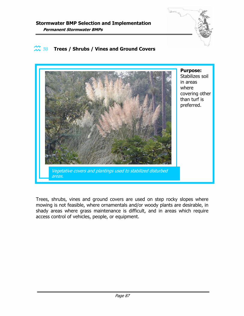
Stormwater BMP Selection and Implementation
Permanent Stormwater BMPs
Page 87
38 Trees / Shrubs / Vines and Ground Covers
Trees, shrubs, vines and ground covers are used on step rocky slopes where mowing is not feasible, where ornamentals and/or woody plants are desirable, in shady areas where grass maintenance is difficult, and in areas which require access control of vehicles, people, or equipment.
Vegetative covers and plantings used to stabilized disturbed areas.
Purpose: Stabilizes soil in areas where covering other than turf is preferred. graphic here…
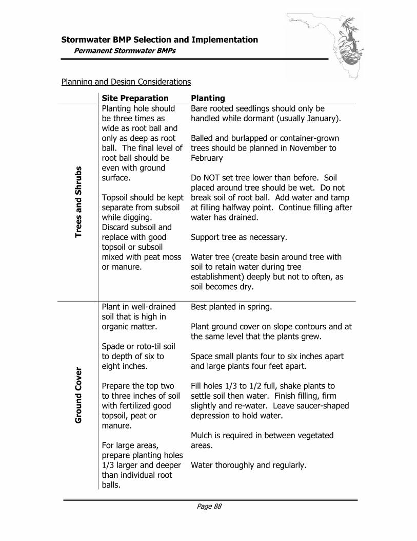
Stormwater BMP Selection and Implementation
Permanent Stormwater BMPs
Page 88
Planning and Design Considerations
Site Preparation Planting
Tree
s an
d Sh
rubs
Planting hole should be three times as wide as root ball and only as deep as root ball. The final level of root ball should be even with ground surface. Topsoil should be kept separate from subsoil while digging. Discard subsoil and replace with good topsoil or subsoil mixed with peat moss or manure.
Bare rooted seedlings should only be handled while dormant (usually January). Balled and burlapped or container-grown trees should be planned in November to February Do NOT set tree lower than before. Soil placed around tree should be wet. Do not break soil of root ball. Add water and tamp at filling halfway point. Continue filling after water has drained. Support tree as necessary. Water tree (create basin around tree with soil to retain water during tree establishment) deeply but not to often, as soil becomes dry.
Gro
un
d C
over
Plant in well-drained soil that is high in organic matter. Spade or roto-til soil to depth of six to eight inches. Prepare the top two to three inches of soil with fertilized good topsoil, peat or manure. For large areas, prepare planting holes 1/3 larger and deeper than individual root balls.
Best planted in spring. Plant ground cover on slope contours and at the same level that the plants grew. Space small plants four to six inches apart and large plants four feet apart. Fill holes 1/3 to 1/2 full, shake plants to settle soil then water. Finish filling, firm slightly and re-water. Leave saucer-shaped depression to hold water. Mulch is required in between vegetated areas. Water thoroughly and regularly.
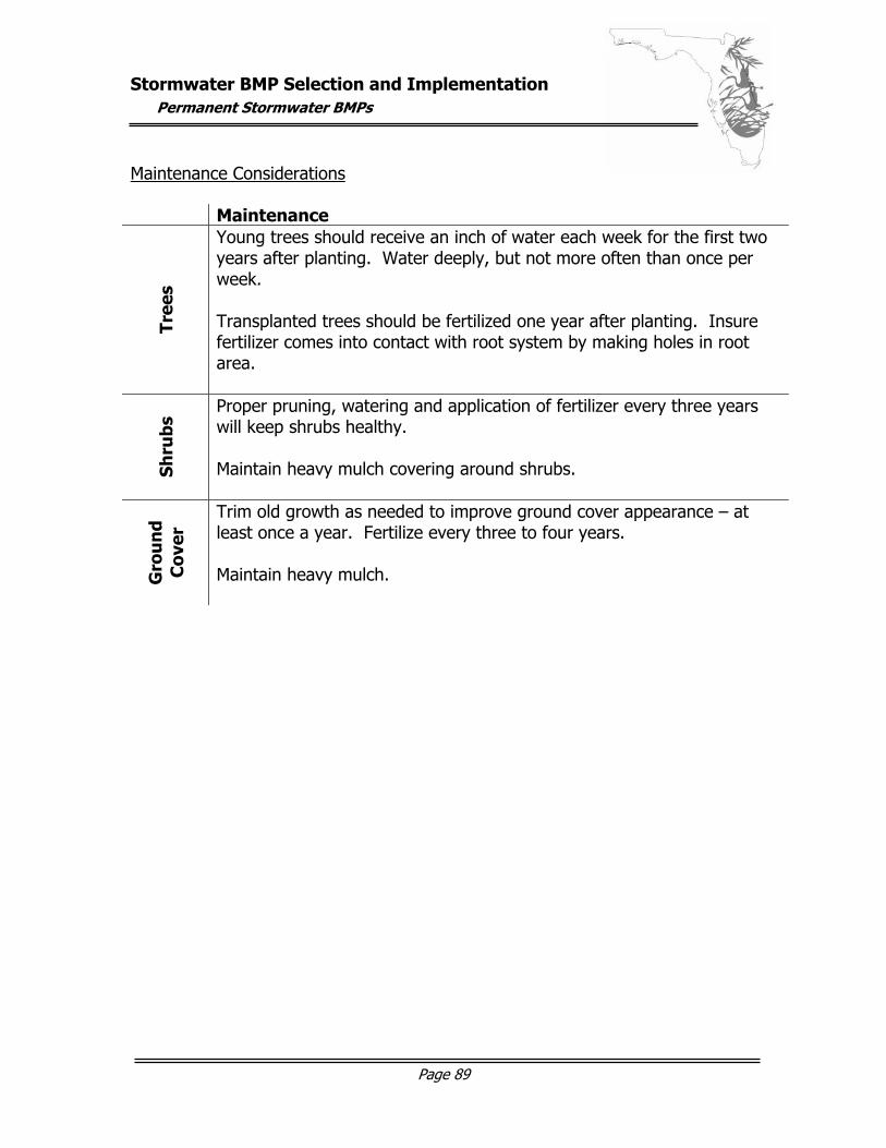
Stormwater BMP Selection and Implementation
Permanent Stormwater BMPs
Page 89
Maintenance Considerations Maintenance
Tree
s
Young trees should receive an inch of water each week for the first two years after planting. Water deeply, but not more often than once per week. Transplanted trees should be fertilized one year after planting. Insure fertilizer comes into contact with root system by making holes in root area.
Shru
bs Proper pruning, watering and application of fertilizer every three years
will keep shrubs healthy. Maintain heavy mulch covering around shrubs.
Gro
un
d C
over
Trim old growth as needed to improve ground cover appearance – at least once a year. Fertilize every three to four years. Maintain heavy mulch.
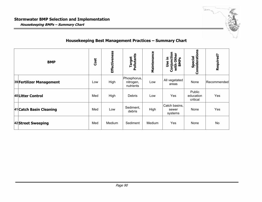
Stormwater BMP Selection and Implementation
Housekeeping BMPs – Summary Chart
Page 90
Housekeeping Best Management Practices – Summary Chart
BMP
Cos
t
Effe
ctiv
enes
s
Targ
et
Pol
luta
nts
Mai
nte
nan
ce
Use
in
Con
jun
ctio
n
wit
h O
ther
B
MP
s
Spec
ial
Con
side
rati
ons
Req
uir
ed?
39 Fertilizer Management Low High Phosphorus,
nitrogen, nutrients
Low All vegetated areas None Recommended
40 Litter Control Med High Debris Low Yes Public
education critical
Yes
41 Catch Basin Cleaning Med Low Sediment, debris High
Catch basins, sewer
systems None Yes
42 Street Sweeping Med Medium Sediment Medium Yes None No
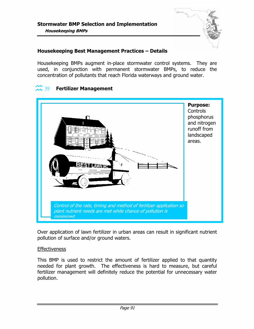
Stormwater BMP Selection and Implementation
Housekeeping BMPs
Page 91
Housekeeping Best Management Practices – Details
Housekeeping BMPs augment in-place stormwater control systems. They are used, in conjunction with permanent stormwater BMPs, to reduce the concentration of pollutants that reach Florida waterways and ground water.
39 Fertilizer Management
Over application of lawn fertilizer in urban areas can result in significant nutrient pollution of surface and/or ground waters.
Effectiveness
This BMP is used to restrict the amount of fertilizer applied to that quantity needed for plant growth. The effectiveness is hard to measure, but careful fertilizer management will definitely reduce the potential for unnecessary water pollution.
Control of the rate, timing and method of fertilizer application so plant nutrient needs are met while chance of pollution is minimized.
Purpose: Controls phosphorus and nitrogen runoff from landscaped areas. graphic here…
Stormwater BMP Selection and Implementation
Housekeeping BMPs
Page 92
Planning Considerations
Although phosphorus is a major water quality concern because it is a primary cause of excessive growth of aquatic plants and algae, it is also necessary to establish a healthy vegetative covering. Phosphorus is essential to seedling growth and should be incorporated into the soil during seedbed preparation. Existing lawns should be aerated before applying phosphorous fertilizer. A soil test should be performed to determine if this fertilization is required. Nitrogen generally brings about the greatest response in plants, but can also be readily soluble and therefore not held by soil particles. Water contamination is most likely when fertilizer is applied to highly permeable sandy soils. A soil test should be performed before applying nitrogen fertilizer to determine appropriate application levels. Lawns should be lightly watered after fertilizer application, but not to the extent that water runs off or leaches the fertilizer through the soil and into the ground water.
Additional Information The Florida Department of Environmental Protection has issued a manual to teach lawn service businesses to use best management practices when practicing lawn maintenance activities. This manual entitled Florida Green Industries: Best Management Practices for Protection of Water Resources in Florida can be found on-line at http://www.dep.state.fl.us/water/stormwater/pubs.htm. The Florida Yards & Neighborhoods Program enlists homeowners in the battle to reduce pollution and enhance the environment by improving home and landscape management. Information about this program, including specific recommendations, checklists, workbooks, training, and links to other informational sources can be found at http://hort.ifas.ufl.edu/FYN/. Specific to fertilization, the Florida Yards and Neighborhoods program makes the recommendations on the following page:
Stormwater BMP Selection and Implementation
Housekeeping BMPs
Page 93
Florida Yards and Neighborhoods Reccomendations:
Slow-Release Nitrogen
Make sure that at least 30 percent of the nitrogen is the slow-release type
Fertilizer Make-Up Nitrogen and potassium should be present in equal values, phosphorus should be half the content of nitrogen and potassium
Hint: The three numbers on fertilizer labels represent nitrogen (first), phosphorus (second) and potassium (third) percentage. Recommended blends include 10-5-10, 16-4-8 and 15-0-15.
To Green Lawns Use chelated iron or iron sulfate instead of complete fertilizer
Maximum Guidelines
Apply no more than one pound of nitrogen per 1,000 ft2 twice per year (Mar. and Oct.). Better to apply ½ pound nitrogen per 1,000 ft2 four times per year (Mar., May, Sep., Nov.)
Hint: To apply ½ pound of nitrogen for a bag of 16-4-8 fertilizer divide the first number (percentage nitrogen) into 50 (50 ÷ 16) to get 3 pounds total fertilizer per 1000 ft2.
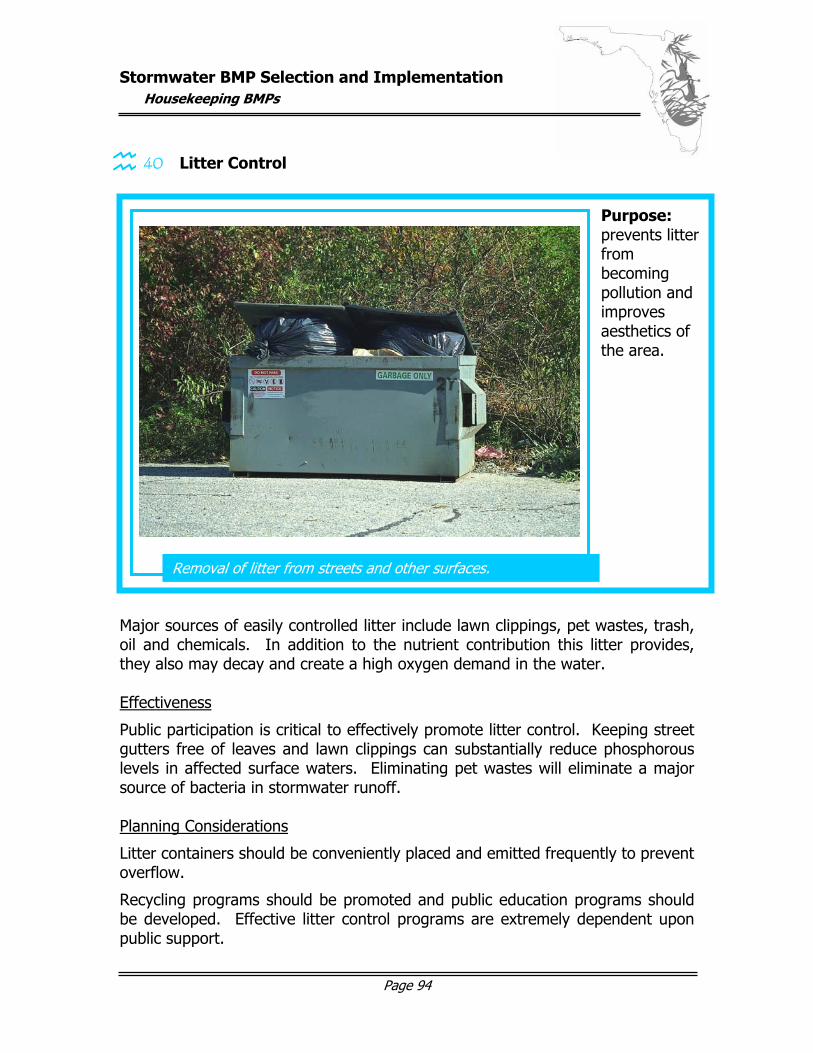
Stormwater BMP Selection and Implementation
Housekeeping BMPs
Page 94
40 Litter Control
Major sources of easily controlled litter include lawn clippings, pet wastes, trash, oil and chemicals. In addition to the nutrient contribution this litter provides, they also may decay and create a high oxygen demand in the water. Effectiveness
Public participation is critical to effectively promote litter control. Keeping street gutters free of leaves and lawn clippings can substantially reduce phosphorous levels in affected surface waters. Eliminating pet wastes will eliminate a major source of bacteria in stormwater runoff. Planning Considerations
Litter containers should be conveniently placed and emitted frequently to prevent overflow.
Recycling programs should be promoted and public education programs should be developed. Effective litter control programs are extremely dependent upon public support.
Removal of litter from streets and other surfaces.
Purpose: prevents litter from becoming pollution and improves aesthetics of the area.
graphic here…
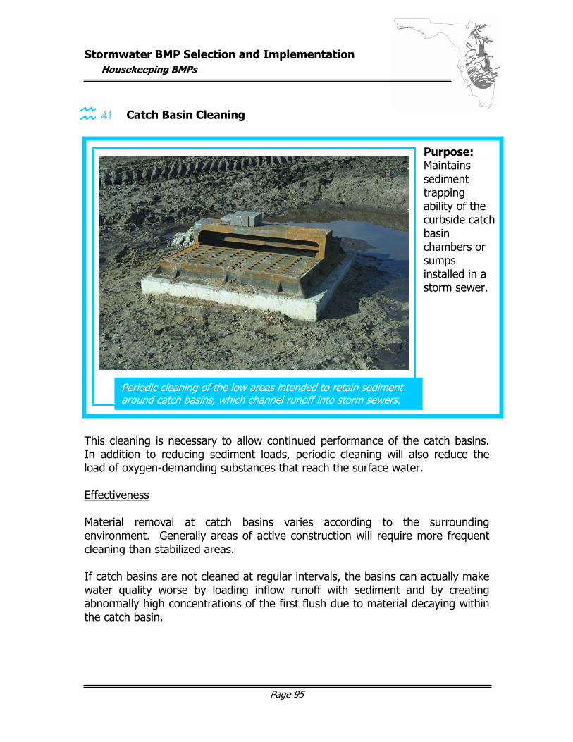
Stormwater BMP Selection and Implementation
Housekeeping BMPs
Page 95
41 Catch Basin Cleaning
This cleaning is necessary to allow continued performance of the catch basins. In addition to reducing sediment loads, periodic cleaning will also reduce the load of oxygen-demanding substances that reach the surface water. Effectiveness Material removal at catch basins varies according to the surrounding environment. Generally areas of active construction will require more frequent cleaning than stabilized areas. If catch basins are not cleaned at regular intervals, the basins can actually make water quality worse by loading inflow runoff with sediment and by creating abnormally high concentrations of the first flush due to material decaying within the catch basin.
Periodic cleaning of the low areas intended to retain sediment around catch basins, which channel runoff into storm sewers.
Purpose: Maintains sediment trapping ability of the curbside catch basin chambers or sumps installed in a storm sewer.
graphic here…
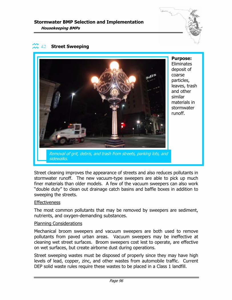
Stormwater BMP Selection and Implementation
Housekeeping BMPs
Page 96
42 Street Sweeping
Street cleaning improves the appearance of streets and also reduces pollutants in stormwater runoff. The new vacuum-type sweepers are able to pick up much finer materials than older models. A few of the vacuum sweepers can also work “double duty” to clean out drainage catch basins and baffle boxes in addition to sweeping the streets.
Effectiveness
The most common pollutants that may be removed by sweepers are sediment, nutrients, and oxygen-demanding substances.
Planning Considerations
Mechanical broom sweepers and vacuum sweepers are both used to remove pollutants from paved urban areas. Vacuum sweepers may be ineffective at cleaning wet street surfaces. Broom sweepers cost lest to operate, are effective on wet surfaces, but create airborne dust during operations.
Street sweeping wastes must be disposed of properly since they may have high levels of lead, copper, zinc, and other wastes from automobile traffic. Current DEP solid waste rules require these wastes to be placed in a Class 1 landfill.
Removal of grit, debris, and trash from streets, parking lots, and sidewalks.
Purpose: Eliminates deposit of coarse particles, leaves, trash and other similar materials in stormwater runoff.
graphic here…
Stormwater BMP Selection and Implementation
References
Page 97
References
Florida Department of Environmental Protection. 1999. The Florida Stormwater, Erosion, and Sedimentation Control Inspector’s Manual. Tallahassee, FL.
Livingston, Eric H. and McCarron, Ellen. 1991. Stormwater Management A Guide for Floridians. Florida Department of Environmental Protection. Tallahassee, FL
Tobiason, Jenkins, Molash, and Rush. 2001. Polymer Use and Testing for Erosion and Sediment Control on Construction Sties. Forester Communications, Inc. / Erosion Control.