Embed Size (px)
Citation preview
ilable at ScienceDirect
Polymer Testing 29 (2010) 132–138
Contents lists ava
Polymer Testing
journal homepage: www.elsevier .com/locate/polytest
Test Method
Strain distribution in cruciform specimens subjected to biaxial loadingconditions. Part 2: Influence of geometrical discontinuities
Ebrahim Lamkanfi a,*, Wim Van Paepegem a, Joris Degrieck a, Carla Ramault b,Andreas Makris b, Danny Van Hemelrijck b
a Department of Materials Science and Engineering, Ghent University, Sint-Pietersnieuwstraat 41, 9000 Ghent, Belgiumb Department of Mechanics of Materials and Constructions, Free University of Brussels, Pleinlaan 2, 1050 Brussels, Belgium
a r t i c l e i n f o
Article history:Received 28 August 2009Accepted 12 October 2009
Keywords:LaminateStrengthStress concentrationsFinite element analysisBiaxial
* Corresponding author. Tel.: þ32 9 264 95 34.E-mail addresses: [email protected],
(E. Lamkanfi).
0142-9418/$ – see front matter � 2009 Elsevier Ltddoi:10.1016/j.polymertesting.2009.10.002
a b s t r a c t
In this paper, the influence of the geometrical design on the strain distribution in cruciformspecimens is investigated. It will be shown that geometrical discontinuities, such as themilled zone and the fillet corners which are, respectively, introduced in the cruciformspecimen to obtain a more uniform biaxial strain distribution and to guide the loads intothe centre zone, result in local high strain concentrations. For this purpose, the digitalimage correlation technique and the finite element method were employed to trace theorigin of these concentrations. It also appeared that the type of load, whether it wasapplied in a uniaxial or biaxial way, had a minor influence on the observed strainconcentrations. The same conclusion could be drawn for the effect of the fibre orientationon the development of these strain intensities. Moreover, this study reveals that thegeometrical irregularities lead to complex stress states which make the cruciform spec-imen fail prematurely. This complicates the determination of the true ultimate biaxialstrength of a composite material.
� 2009 Elsevier Ltd. All rights reserved.
1. Introduction
From the early seventies, many attempts have beenmade by several researchers [5,8] to perform biaxial testson different kinds of polymer composites. Tubular speci-mens were the earliest geometrical types that were used toobtain a bidirectional stress state. One of the main reasonswhy alternative geometries were explored for biaxialtesting applications was that the use of internal pressure, incombination with axial or torsional forces, led to significantbuilt-up of stresses in the thickness direction [1,2]. Thedominant effect of these thickness stresses on the overallstress state of the material indicated that these types oftests could give an insight only into tubular-like
. All rights reserved.
applications such as pressure vessels. Consequently, inother applications where the through-thickness stressesand strains are negligible, flat specimens would be moresuitable to obtain more realistic stress–strain relationshipsand, therefore, also better predictions for failure andstrength criteria could be expected. Besides the develop-ment of a wide range of loading systems, a variety of cross-shaped geometries have been investigated with always thesame and obvious requirement in mind: the load has to betransferred in a proper way to the center zone of thespecimen, where the biaxial loading state is intended to bebuilt-up uniformly. The aim of this paper is to presentnumerical and experimental results describing in detailhow this condition of uniform strain distribution in thebiaxial characterization of composite materials is affectedby discontinuities in the cruciform geometry. First, thedesign philosophy which has been used by previousresearchers will be discussed briefly. This discussion isnecessary to position the investigated cross-shaped
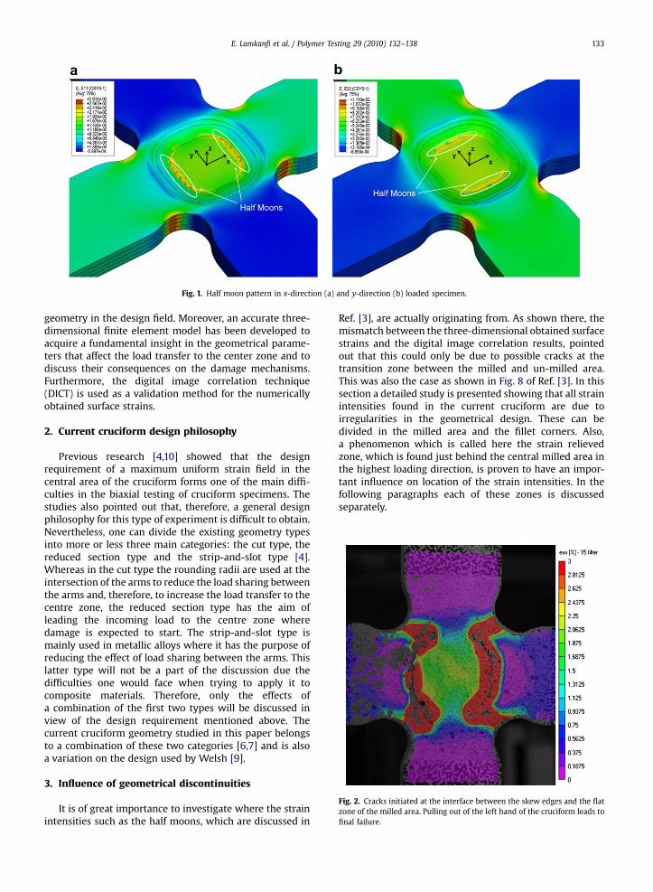
Fig. 1. Half moon pattern in x-direction (a) and y-direction (b) loaded specimen.
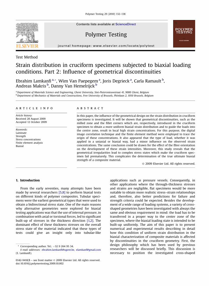
Fig. 2. Cracks initiated at the interface between the skew edges and the flatzone of the milled area. Pulling out of the left hand of the cruciform leads tofinal failure.
E. Lamkanfi et al. / Polymer Testing 29 (2010) 132–138 133
geometry in the design field. Moreover, an accurate three-dimensional finite element model has been developed toacquire a fundamental insight in the geometrical parame-ters that affect the load transfer to the center zone and todiscuss their consequences on the damage mechanisms.Furthermore, the digital image correlation technique(DICT) is used as a validation method for the numericallyobtained surface strains.
2. Current cruciform design philosophy
Previous research [4,10] showed that the designrequirement of a maximum uniform strain field in thecentral area of the cruciform forms one of the main diffi-culties in the biaxial testing of cruciform specimens. Thestudies also pointed out that, therefore, a general designphilosophy for this type of experiment is difficult to obtain.Nevertheless, one can divide the existing geometry typesinto more or less three main categories: the cut type, thereduced section type and the strip-and-slot type [4].Whereas in the cut type the rounding radii are used at theintersection of the arms to reduce the load sharing betweenthe arms and, therefore, to increase the load transfer to thecentre zone, the reduced section type has the aim ofleading the incoming load to the centre zone wheredamage is expected to start. The strip-and-slot type ismainly used in metallic alloys where it has the purpose ofreducing the effect of load sharing between the arms. Thislatter type will not be a part of the discussion due thedifficulties one would face when trying to apply it tocomposite materials. Therefore, only the effects ofa combination of the first two types will be discussed inview of the design requirement mentioned above. Thecurrent cruciform geometry studied in this paper belongsto a combination of these two categories [6,7] and is alsoa variation on the design used by Welsh [9].
3. Influence of geometrical discontinuities
It is of great importance to investigate where the strainintensities such as the half moons, which are discussed in
Ref. [3], are actually originating from. As shown there, themismatch between the three-dimensional obtained surfacestrains and the digital image correlation results, pointedout that this could only be due to possible cracks at thetransition zone between the milled and un-milled area.This was also the case as shown in Fig. 8 of Ref. [3]. In thissection a detailed study is presented showing that all strainintensities found in the current cruciform are due toirregularities in the geometrical design. These can bedivided in the milled area and the fillet corners. Also,a phenomenon which is called here the strain relievedzone, which is found just behind the central milled area inthe highest loading direction, is proven to have an impor-tant influence on location of the strain intensities. In thefollowing paragraphs each of these zones is discussedseparately.
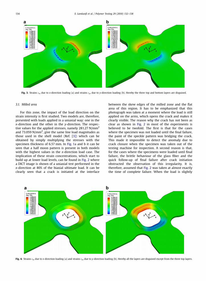
Fig. 3. Strains 3xz due to x-direction loading (a) and strains 3yz due to y-direction loading (b). Hereby the three top and bottom layers are disguised.
E. Lamkanfi et al. / Polymer Testing 29 (2010) 132–138134
3.1. Milled area
For this zone, the impact of the load direction on thestrain intensity is first studied. Two models are, therefore,presented with loads applied in a uniaxial way: one in thex-direction and the other in the y-direction. The respec-tive values for the applied stresses, namely 281.27 N/mm2
and 73.059 N/mm2, give the same line load magnitudes asthose used in the shell model (Ref. [3]) which can beobtained by simply multiplying the stresses with thespecimen thickness of 6.57 mm. In Fig. 1a and b it can beseen that a half moon pattern is present in both modelswith the highest values in the x-direction load case. Theimplication of these strain concentrations, which start tobuild up at lower load levels, can be found in Fig. 2 wherea DICT image is shown of a uniaxial test performed in thex-direction at 80% of the biaxial ultimate load. It can beclearly seen that a crack is initiated at the interface
Fig. 4. Strains 3xz due to x-direction loading (a) and strains 3yz due to y-direction loa
between the skew edges of the milled zone and the flatarea of this region. It has to be emphasized that thisphotograph was taken at a moment where the load is stillapplied on the arms, which opens the crack and makes itclearly visible. The reason why the crack has not been asclear as shown in Fig. 2 in most of the experiments isbelieved to be twofold. The first is that for the caseswhere the specimen was not loaded until the final failure,the paint of the speckle pattern was bridging the crack.This made it impossible to detect the anomaly due tocrack closure when the specimen was taken out of thetesting machine for inspection. A second reason is that,for the cases where the specimens were loaded until finalfailure, the brittle behaviour of the glass fiber and thequick follow-up of final failure after crack initiationobstructed the observation of this irregularity. It is,therefore, assumed that Fig. 2 was taken at almost exactlythe time of complete failure. When the load is slightly
ding (b). Hereby all the layers are disguised except from the three top layers.
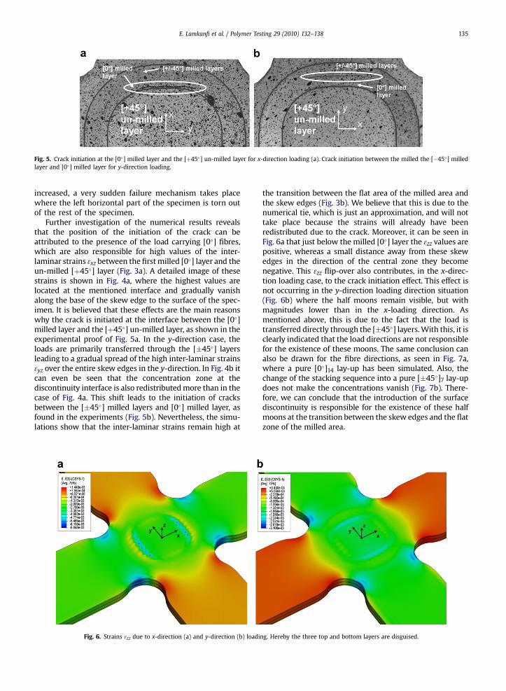
Fig. 5. Crack initiation at the [0�] milled layer and the [þ45�] un-milled layer for x-direction loading (a). Crack initiation between the milled the [�45�] milledlayer and [0�] milled layer for y-direction loading.
E. Lamkanfi et al. / Polymer Testing 29 (2010) 132–138 135
increased, a very sudden failure mechanism takes placewhere the left horizontal part of the specimen is torn outof the rest of the specimen.
Further investigation of the numerical results revealsthat the position of the initiation of the crack can beattributed to the presence of the load carrying [0�] fibres,which are also responsible for high values of the inter-laminar strains 3xz between the first milled [0�] layer and theun-milled [þ45�] layer (Fig. 3a). A detailed image of thesestrains is shown in Fig. 4a, where the highest values arelocated at the mentioned interface and gradually vanishalong the base of the skew edge to the surface of the spec-imen. It is believed that these effects are the main reasonswhy the crack is initiated at the interface between the [0�]milled layer and the [þ45�] un-milled layer, as shown in theexperimental proof of Fig. 5a. In the y-direction case, theloads are primarily transferred through the [�45�] layersleading to a gradual spread of the high inter-laminar strains3yz over the entire skew edges in the y-direction. In Fig. 4b itcan even be seen that the concentration zone at thediscontinuity interface is also redistributed more than in thecase of Fig. 4a. This shift leads to the initiation of cracksbetween the [�45�] milled layers and [0�] milled layer, asfound in the experiments (Fig. 5b). Nevertheless, the simu-lations show that the inter-laminar strains remain high at
Fig. 6. Strains 3zz due to x-direction (a) and y-direction (b) loadi
the transition between the flat area of the milled area andthe skew edges (Fig. 3b). We believe that this is due to thenumerical tie, which is just an approximation, and will nottake place because the strains will already have beenredistributed due to the crack. Moreover, it can be seen inFig. 6a that just below the milled [0�] layer the 3zz values arepositive, whereas a small distance away from these skewedges in the direction of the central zone they becomenegative. This 3zz flip-over also contributes, in the x-direc-tion loading case, to the crack initiation effect. This effect isnot occurring in the y-direction loading direction situation(Fig. 6b) where the half moons remain visible, but withmagnitudes lower than in the x-loading direction. Asmentioned above, this is due to the fact that the load istransferred directly through the [�45�] layers. With this, it isclearly indicated that the load directions are not responsiblefor the existence of these moons. The same conclusion canalso be drawn for the fibre directions, as seen in Fig. 7a,where a pure [0�]14 lay-up has been simulated. Also, thechange of the stacking sequence into a pure [�45�]7 lay-updoes not make the concentrations vanish (Fig. 7b). There-fore, we can conclude that the introduction of the surfacediscontinuity is responsible for the existence of these halfmoons at the transition between the skew edges and the flatzone of the milled area.
ng. Hereby the three top and bottom layers are disguised.
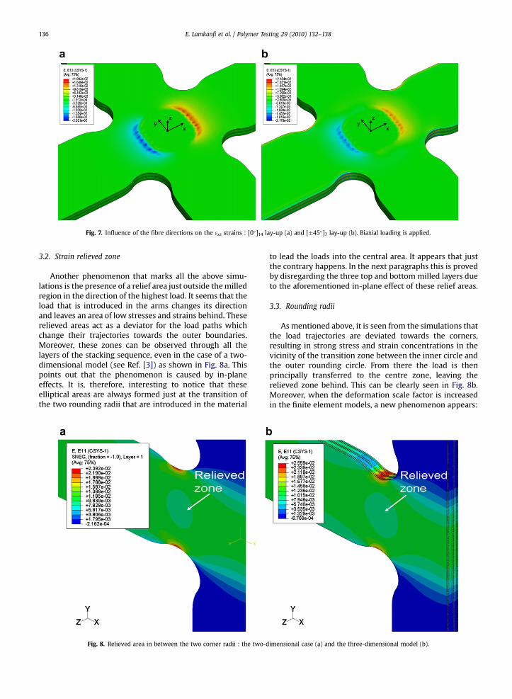
Fig. 7. Influence of the fibre directions on the 3xz strains : [0�]14 lay-up (a) and [�45�]7 lay-up (b). Biaxial loading is applied.
E. Lamkanfi et al. / Polymer Testing 29 (2010) 132–138136
3.2. Strain relieved zone
Another phenomenon that marks all the above simu-lations is the presence of a relief area just outside the milledregion in the direction of the highest load. It seems that theload that is introduced in the arms changes its directionand leaves an area of low stresses and strains behind. Theserelieved areas act as a deviator for the load paths whichchange their trajectories towards the outer boundaries.Moreover, these zones can be observed through all thelayers of the stacking sequence, even in the case of a two-dimensional model (see Ref. [3]) as shown in Fig. 8a. Thispoints out that the phenomenon is caused by in-planeeffects. It is, therefore, interesting to notice that theseelliptical areas are always formed just at the transition ofthe two rounding radii that are introduced in the material
Fig. 8. Relieved area in between the two corner radii : the two-d
to lead the loads into the central area. It appears that justthe contrary happens. In the next paragraphs this is provedby disregarding the three top and bottom milled layers dueto the aforementioned in-plane effect of these relief areas.
3.3. Rounding radii
As mentioned above, it is seen from the simulations thatthe load trajectories are deviated towards the corners,resulting in strong stress and strain concentrations in thevicinity of the transition zone between the inner circle andthe outer rounding circle. From there the load is thenprincipally transferred to the centre zone, leaving therelieved zone behind. This can be clearly seen in Fig. 8b.Moreover, when the deformation scale factor is increasedin the finite element models, a new phenomenon appears:
imensional case (a) and the three-dimensional model (b).
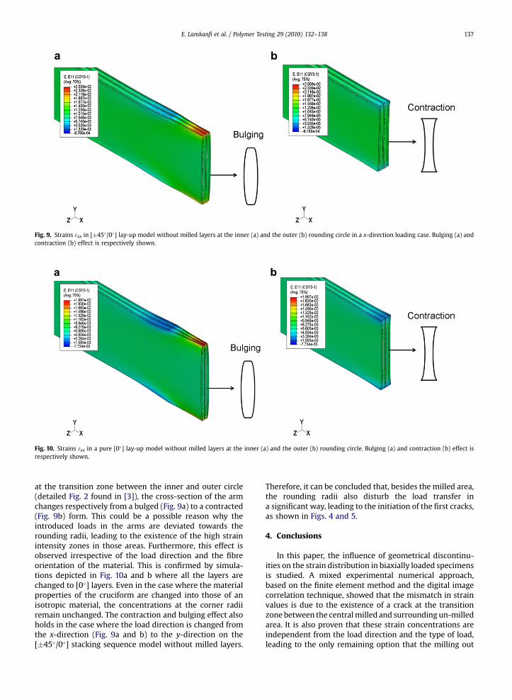
Fig. 9. Strains 3xx in [�45�/0�] lay-up model without milled layers at the inner (a) and the outer (b) rounding circle in a x-direction loading case. Bulging (a) andcontraction (b) effect is respectively shown.
Fig. 10. Strains 3xx in a pure [0�] lay-up model without milled layers at the inner (a) and the outer (b) rounding circle. Bulging (a) and contraction (b) effect isrespectively shown.
E. Lamkanfi et al. / Polymer Testing 29 (2010) 132–138 137
at the transition zone between the inner and outer circle(detailed Fig. 2 found in [3]), the cross-section of the armchanges respectively from a bulged (Fig. 9a) to a contracted(Fig. 9b) form. This could be a possible reason why theintroduced loads in the arms are deviated towards therounding radii, leading to the existence of the high strainintensity zones in those areas. Furthermore, this effect isobserved irrespective of the load direction and the fibreorientation of the material. This is confirmed by simula-tions depicted in Fig. 10a and b where all the layers arechanged to [0�] layers. Even in the case where the materialproperties of the cruciform are changed into those of anisotropic material, the concentrations at the corner radiiremain unchanged. The contraction and bulging effect alsoholds in the case where the load direction is changed fromthe x-direction (Fig. 9a and b) to the y-direction on the[�45�/0�] stacking sequence model without milled layers.
Therefore, it can be concluded that, besides the milled area,the rounding radii also disturb the load transfer ina significant way, leading to the initiation of the first cracks,as shown in Figs. 4 and 5.
4. Conclusions
In this paper, the influence of geometrical discontinu-ities on the strain distribution in biaxially loaded specimensis studied. A mixed experimental numerical approach,based on the finite element method and the digital imagecorrelation technique, showed that the mismatch in strainvalues is due to the existence of a crack at the transitionzone between the central milled and surrounding un-milledarea. It is also proven that these strain concentrations areindependent from the load direction and the type of load,leading to the only remaining option that the milling out
E. Lamkanfi et al. / Polymer Testing 29 (2010) 132–138138
itself is responsible for these strain concentrations.Furthermore, it is found that the existence of a relieved zonein the direction of the highest load, just behind the milledarea, diverts the incoming load trajectories to the corners,resulting also in high intensity zones there. It can, therefore,be concluded that these geometrical discontinuities havea major influence on the strain distribution, inducing thecruciform to fail prematurely before the ultimate biaxialstrength is reached.
Acknowledgements
The authors gratefully acknowledge the financial supportfor this research by the Fund for Scientific Research – Flan-ders (FWO).
References
[1] M.F.S. AlKhalil, P.D. Soden, R. Kitching, M.J. Hinton, The effects ofradial stresses on the strength of thin-walled filament wound GRPcomposite pressure cylinders. International Journal of MechanicalSciences 38 (1) (1996) 97–120.
[2] V.K.S. Choo, D. Hull, Influence of radial compressive stress owing topressure on the failure modes of composite tube specimens. Journalof Composite Materials 17 (4) (1983) 344–356.
[3] E. Lamkanfi, W. Van Paepegem, J. Degrieck, C. Ramault, A. Makris,D. Van Hemelrijck, Strain distribution in cruciform specimens sub-jected to biaxial loading conditions. Part 1: two-dimensional versusthree-dimensional finite element model. Polymer Testing 29 (1)(2010) 7–13.
[4] Y. Ohtake, S. Rokugawa, H. Masumoto, Geometry determination ofcruciform-type specimen and biaxial tensile test of C C composites.High Temperature Ceramic Matrix Composites Iii 164-1 (1999)151–154.
[5] V.D. Protasov, V.P. Georgievskii, Anisotropy of the strength proper-ties of reinforced plastics. Mechanics of Composite Materials 3 (3)(1967) 308–311.
[6] A. Smits, D. Van Hemelrijck, T.P. Philippidis, A. Cardon, Optimizationof a cruciform test specimen for biaxial loading of fiber reinforcedmaterial systems, in: Proceedings of 11th European Conference onComposite Materials, Rhodes, Greece, 2004.
[7] A. Smits, D. Van Hemelrijck, T.P. Philippidis, A. Cardon, Design ofa cruciform specimen for biaxial testing of fibre reinforcedcomposite laminates. Composites Science and Technology 66 (7–8)(2006) 964–975.
[8] H. Thom, A review of the biaxial strength of fibre-reinforced plastics.Composites Part A-Applied Science and Manufacturing 29 (8) (1998)869–886.
[9] J.S. Welsh, D.F. Adams, An experimental investigation of the biaxialstrength of IM6/3501-6 carbon/epoxy cross-ply laminates usingcruciform specimens. Composites Part A-Applied Science andManufacturing 33 (6) (2002) 829–839.
[10] Y. Yu, M. Wan, X.D. Wu, X.B. Zhou, Design of a cruciform biaxialtensile specimen for limit strain analysis by FEM. Journal of Mate-rials Processing Technology 123 (1) (2002) 67–70.


![Aalborg Universitet Biaxial Fatigue Testing and Simulation ... · specimen from [11] when milling is employed to decrease the thickness of the gauge zone of the cruciform test specimens](https://img.pdfslide.net/doc/110x75/5e1fa7890bddcc0da93d0cdf/aalborg-universitet-biaxial-fatigue-testing-and-simulation-specimen-from-11.jpg)