Embed Size (px)
Citation preview
This article was downloaded by: [Moskow State Univ Bibliote]On: 08 September 2013, At: 02:06Publisher: Taylor & FrancisInforma Ltd Registered in England and Wales Registered Number:1072954 Registered office: Mortimer House, 37-41 Mortimer Street,London W1T 3JH, UK
The Journal of AdhesionPublication details, including instructions forauthors and subscription information:http://www.tandfonline.com/loi/gadh20
Stress Analysis of AdhesiveBonded Tubular Lap JointsR. D. Adams a & N. A. Peppiatt aa Department of Mechanical Engineering,University of Bristol, Queen's Building.University Walk, Bristol, BS8 1TR, EnglandPublished online: 13 Dec 2006.
To cite this article: R. D. Adams & N. A. Peppiatt (1977) Stress Analysis ofAdhesive Bonded Tubular Lap Joints, The Journal of Adhesion, 9:1, 1-18
To link to this article: http://dx.doi.org/10.1080/00218467708075095
PLEASE SCROLL DOWN FOR ARTICLE
Taylor & Francis makes every effort to ensure the accuracy of allthe information (the “Content”) contained in the publications on ourplatform. However, Taylor & Francis, our agents, and our licensorsmake no representations or warranties whatsoever as to the accuracy,completeness, or suitability for any purpose of the Content. Any opinionsand views expressed in this publication are the opinions and views ofthe authors, and are not the views of or endorsed by Taylor & Francis.The accuracy of the Content should not be relied upon and should beindependently verified with primary sources of information. Taylor andFrancis shall not be liable for any losses, actions, claims, proceedings,demands, costs, expenses, damages, and other liabilities whatsoeveror howsoever caused arising directly or indirectly in connection with, inrelation to or arising out of the use of the Content.
This article may be used for research, teaching, and private studypurposes. Any substantial or systematic reproduction, redistribution,reselling, loan, sub-licensing, systematic supply, or distribution in anyform to anyone is expressly forbidden. Terms & Conditions of access
and use can be found at http://www.tandfonline.com/page/terms-and-conditions
Dow
nloa
ded
by [
Mos
kow
Sta
te U
niv
Bib
liote
] at
02:
06 0
8 Se
ptem
ber
2013
J.A&&n, 1917. Vol. 9, pp. 1-18 0 Gordon and Breach Science Publishers Ltd., 1977 Printed in Scotland
Stress Analysis of Adhesive Bonded Tubular Lap Joints
R. D. ADAMS and N. A. PEPPIATT
Department of Mechanical Engineering. University of Bristol. Queen‘s Building, University Walk, Bristol BS8 1 TR, England
(Received July 30, 1976)
The stresses in adhesive bonded tubular lap joints, subjected to axial and torsional loads, have been analysed using axisymmetric quadratic isoparametric finite elements. In the axial load case, the results are compared with a previously published closed-form solution and in the torsional case the results are compared with a closed-form solution presented here. The influences on the stress distributions of an adhesive fillet and of partial tapering of the adherends are also investigated, and an extension to the range of validity of Goland and Reissner’s second criterion is proposed.
Notation
2a E El7 F G G O J I n r t T
Diameter of adhesive layer Young’s modulus of adherend tube Young’s modulus of adhesive layer Applied load Shear modulus of adherend tube Shear modulus of adhesive layer Polar moment of inertia of adherends Overlap length of joint Ratio of end thickness to wall thickness of tubes (scarf joints) Radius of tubes Wall thickness of tube Torque Cylindrical coordinates Shear strain Thickness of adhesive layer Poisson’s ratio Normal stress Shear stress
1 1
Dow
nloa
ded
by [
Mos
kow
Sta
te U
niv
Bib
liote
] at
02:
06 0
8 Se
ptem
ber
2013
2 R. D. ADAMS AND N. A. PEPPIA'IT
Subscripts a Refers to adhesive layer 1 Refers to inner adherend 2 Refers to outer adherend i o
Refers to inner radius of tube Refers to outer radius of tube
1. INTRODUCTION
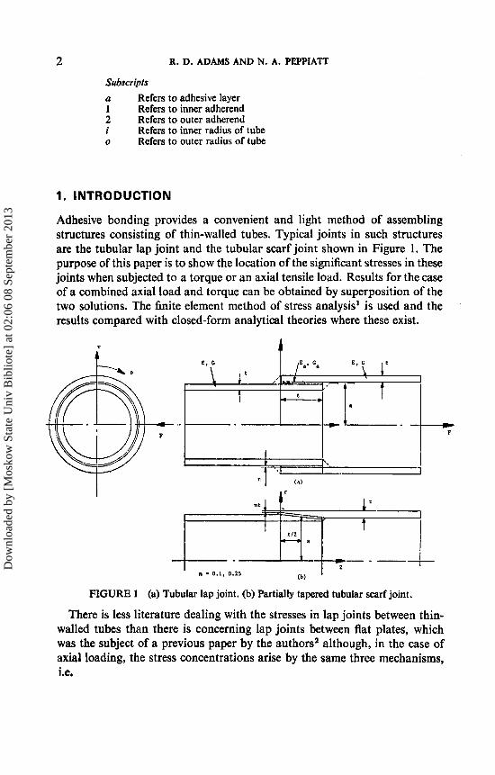
Adhesive bonding provides a convenient and light method of assembling structures consisting of thin-walled tubes. Typical joints in such structures are the tubular lap joint and the tubular scarf joint shown in Figure 1. The purpose of this paper is to show the location of the significant stresses in these joints when subjected to a torque or an axial tensile load. Results for the case of a combined axial load and torque can be obtained by superposition of the two solutions. The finite element method of stress analysis' is used and the results compared with closed-form analytical theories where these exist.
--c F
~ n : % l y ; c
I
- . -- (b) n - 0.1, 0.25
FIGURE 1 (a) Tubular lap joint. (b) Partially tapered tubular scarf joint.
There is less literature dealing with the stresses in lap joints between thin- walled tubes than there is concerning lap joints between flat plates, which was the subject of a previous paper by the authorsz although, in the case of axial loading, the stress concentrations arise by the same three mechanisms, i.e.
Dow
nloa
ded
by [
Mos
kow
Sta
te U
niv
Bib
liote
] at
02:
06 0
8 Se
ptem
ber
2013
STRESS ANALYSIS OF TUBULAR LAP JOINTS 3
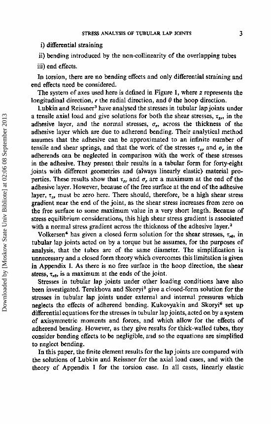
i) differential straining ii) bending introduced by the non-collinearity of the overlapping tubes iii) end effects. In torsion, there are no bending effects and only differential straining and
end effects need be considered. The system of axes used here is defined in Figure 1, where z represents the
longitudinal direction, r the radial direction, and 8 the hoop direction. Lubkin and Reissner3 have analysed the stresses in tubular lap joints under
a tensile axial load and give solutions for both the shear stresses, zZr, in the adhesive layer, and the normal stresses, a,, across the thickness of the adhesive layer which are due to adherend bending. Their analytical method assumes that the adhesive can be approximated to an infinite number of tensile and shear springs, and that the work of the stresses z,, and a, in the adherends can be neglected in comparison with the work of these stresses in the adhesive. They present their results in a tabular form for forty-eight joints with different geometries and (always linearly elastic) material pro- perties. These results show that T,, and a, are a maximum at the end of the adhesive layer. However, because of the free surface at the end of the adhesive layer, z,, must be zero here. There should, therefore, be a high shear stress gradient near the end of the joint, as the shear stress increases from zero on the free surface to some maximum value in a very short length. Because of stress equilibrium considerations, this high shear stress gradient is associated with a normal stress gradient across the thickness of the adhesive layer.2
Volkersen4 has given a closed form solution for the shear stresses, z,, in tubular lap joints acted on by a torque but he assumes, for the purposes of analysis, that the tubes are of the same diameter. The simplification is unnecessary and a closed form theory which overcomes this limitation is given in Appendix I. As there is no free surface in the hoop direction, the shear stress, zr0, is a maximum at the ends of the joint.
Stresses in tubular lap joints under other loading conditions have also been investigated. Terekhova and Skoryi5 give a closed-form solution for the stresses in tubular lap joints under external and internal pressures which neglects the effects of adherend bending. Kukovyakin and Skoryi6 set up differential equations for the stresses in tubular lap joints, acted on by a system of axisymmetric moments and forces, and which allow for the effects of adherend bending. However, as they give results for thick-walled tubes, they consider bending effects to be negligible, and so the equations are simplified to neglect bending.
In this paper, the finite element results for the lap joints are compared with the solutions of Lubkin and Reissner for the axial load cases, and with the theory of Appendix I for the torsion case. In all cases, linearly elastic
Dow
nloa
ded
by [
Mos
kow
Sta
te U
niv
Bib
liote
] at
02:
06 0
8 Se
ptem
ber
2013
4 R. D. A D A M S AND N. A. PEPPIATT
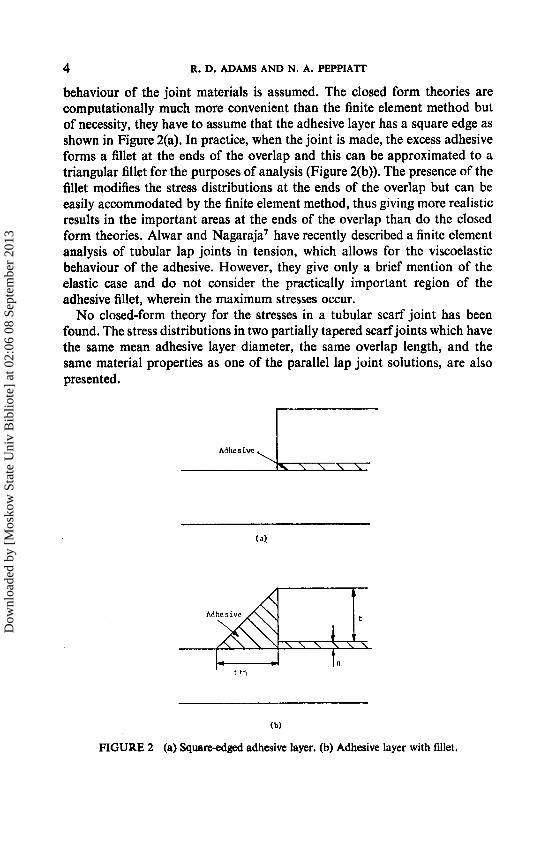
behaviour of the joint materials is assumed. The closed form theories are computationally much more convenient than the finite element method but of necessity, they have to assume that the adhesive layer has a square edge as shown in Figure 2(a). In practice, when the joint is made, the excess adhesive forms a fillet at the ends of the overlap and this can be approximated to a triangular fillet for the purposes of analysis (Figure 2(b)). The presence of the fillet modifies the stress distributions at the ends of the overlap but can be easily accommodated by the finite element method, thus giving more realistic results in the important areas at the ends of the overlap than do the closed form theories. Alwar and Nagaraja’ have recently described a finite element analysis of tubular lap joints in tension, which allows for the viscoelastic behaviour of the adhesive. However, they give only a brief mention of the elastic case and do not consider the practically important region of the adhesive fillet, wherein the maximum stresses occur.
No closed-form theory for the stresses in a tubular scarf joint has been found. The stress distributions in two partially tapered scarf joints which have the same mean adhesive layer diameter, the same overlap length, and the same material properties as one of the parallel lap joint solutions, are also presented.
Adhes ive
\ \ \ \
(b)
FIGURE 2 (a) Squareedged adhesive layer. (b) Adhesive layer with fillet.
Dow
nloa
ded
by [
Mos
kow
Sta
te U
niv
Bib
liote
] at
02:
06 0
8 Se
ptem
ber
2013
STRESS ANALYSIS OF TUBULAR LAP JOINTS 5
2. FINITE ELEMENT ANALYSIS AND MESHES
The finite element program uses the 8-node isoparametric element' which has been advocated by Bond, et aI.* as a good element for general use. It has been shown that, for axisymmetric problems, of which the tubular joint considered here is an example, the axial loading case is a two degree of freedom per node problem and the torsion case is a single degree of freedom per node p r ~ b l e m . ~
In the case of axial loading, the stresses or, o,, o,, T~~ and the principal stresses and directions are computed at each of the four Gauss quadrature (sampling) points in each element, and a plot of the principal stresses is produced. In the case of the tractions in the hoop, 8, direction, the stresses zr0 and zz0 are computed at each of the Gauss points. Additionally, the stresses at the comer nodes are predicted in both cases from the Gauss point values by the least squares method of Hinton, et ~ 1 . ' ~
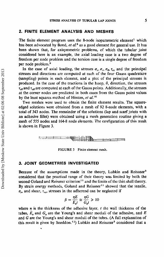
Two meshes were used to obtain the finite element results. The square- edged solutions were obtained from a mesh of 92 8-node elements, with a total of 343 nodes. The remainder of the solutions (lap and scarf joints with an adhesive fillet) were obtained using a mesh generation routine giving a mesh of 555 nodes and 164-8 node elements. The configuration of this mesh is shown in Figure 3.
FIGURE 3 Finite element mesh.
3. JOINT GEOMETRIES INVESTIGATED
Because of the assumptions made in the theory, Lubkin and Reissner3 considered that the practical range of their theory was limited by both the second Goland and Reissner criterion" and the limits of the thin shell theory. By strain energy methods, Goland and Reissner" showed that the tensile, or, and shear, T ~ ~ , stresses in the adherend can be neglected if
where q is the thickness of the adhesive layer, t the wall thickness of the tubes, E,, and G, are the Young's and shear moduli of the adhesive, and E and G are the Young's and shear moduli of the tubes. (A full explanation of this result is given by Sneddon.12) Lubkin and Reissner3 considered that a
.3
Dow
nloa
ded
by [
Mos
kow
Sta
te U
niv
Bib
liote
] at
02:
06 0
8 Se
ptem
ber
2013
6 R. D. ADAMS AND N. A. PEPPIATT
value of t
2a R = - = 0.10
where 2a is the diameter of the adhesive layer, was near the limits of the thin shell theory, i.e. for the theory to apply R < 0.10.
The finite element results have been compared with three sets of results from Table I in Lubkin and Rei~sner .~ One case was chosen to be well within the practical bounds of the theory; the second was chosen to be outside the bounds of the Goland and Reissner criterion; the third was chosen to be outside the bounds of the Goland and Reissner criterion and at what Lubkin and Reissner considered to be the practical limits of the thin shell theory.
The three cases taken were 1 t 1 t
1 t
1) p = 20, - = 10, R = 0.025,
2) p = 4, - = 10, R = 0.025,
3 ) p = 4, - = 10, R = 0.10.
where p and R are as defined previously, and 1 is the overlap length. It can be seen that cases (2) and (3) are outside the limits of the Goland
and Reissner criterion, and case (3) is near the limits of the thin shell theory. Parametric studies cannot easily be performed using the finite element
method, so the finite element models were given the following dimensions: q = 0.2 mm, t = 1.0 mm, 1 = lOmm,
overall adherend length = 40 mm. For R = 0.025, a = 20 mm; for R = 0.10, a = 5 mm.
The following material properties were also assumed : E = 70 000 MN m-’, V, = 0.3, v = 0.3333;
for p = 20, E, = 700 MN m-2; for /l = 4, E, = 3500 MN m-2 (this value is typical of a modified epoxy adhesive).
The same three sets of geometrical and material properties are used to compare the results obtained in the torsion case from the closed form theory (Appendix I) with the finite element results. This theory neglects the shear stresses, t re , in the adherends, and so the Goland and Reissner criterion again applies. Thus, cases (2) and (3) are outside the bounds of the criterion.
Jr
Dow
nloa
ded
by [
Mos
kow
Sta
te U
niv
Bib
liote
] at
02:
06 0
8 Se
ptem
ber
2013
STRESS ANALYSIS OF TUBULAR LAP JOINTS 7
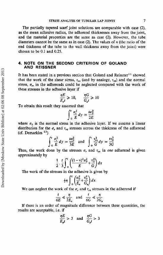
The partially tapered scarf joint solutions are comparable with case (2), as the mean adhesive radius, the adherend thicknesses away from the joint, and the material properties are the same as case (2). However, the tube diameters cannot be the same as in case (2). The values of n (the ratio of the end thickness of the tube to the wall thickness away from the joint) were chosen to be 0.1 and 0.25.
4. NOTE ON THE SECOND CRITERION OF GOLAND
It has been stated in a previous section that Goland and Reissner" showed that the work of the shear stress, z,, (and by analogy, rro) and the normal stress, a,, in the adherends could be neglected compared with the work of these stresses in the adhesive layer if
AND REISSNER
To obtain this result they assumed that tog 2E
where oo is the normal stress in the adhesive layer. If we assume a linear distribution for the a, and z,, stresses across the thickness of the adherend (cf. Demarkies 13)
Thus, the work done by the stresses a, and zrz in one adherend is given approximately by
The work of the stresses in the adhesive is given by
We can neglect the work of the ar and zrz stresses in the adherend if t ? t ? - < - and -4-
6E 2Ea 6G 2Ga If there is an order of magnitude difference between these quantities, the
results are acceptable, i.e. if
Dow
nloa
ded
by [
Mos
kow
Sta
te U
niv
Bib
liote
] at
02:
06 0
8 Se
ptem
ber
2013
8 R. D. ADAMS AND N. A. PEPPIATT
This result suggests that cases (2) and (3) should now be within the range of validity of Lubkin and Reissner’s theory. In more general terms, it is useful in that it brings the range of validity of Goland and Reissner’s second theory for flat lap joints and Lubkin and Reissner’s theory for tubular lap joints closer to many practical joints.
5. RESULTS AND DISCUSSION
5.1 Tension cases
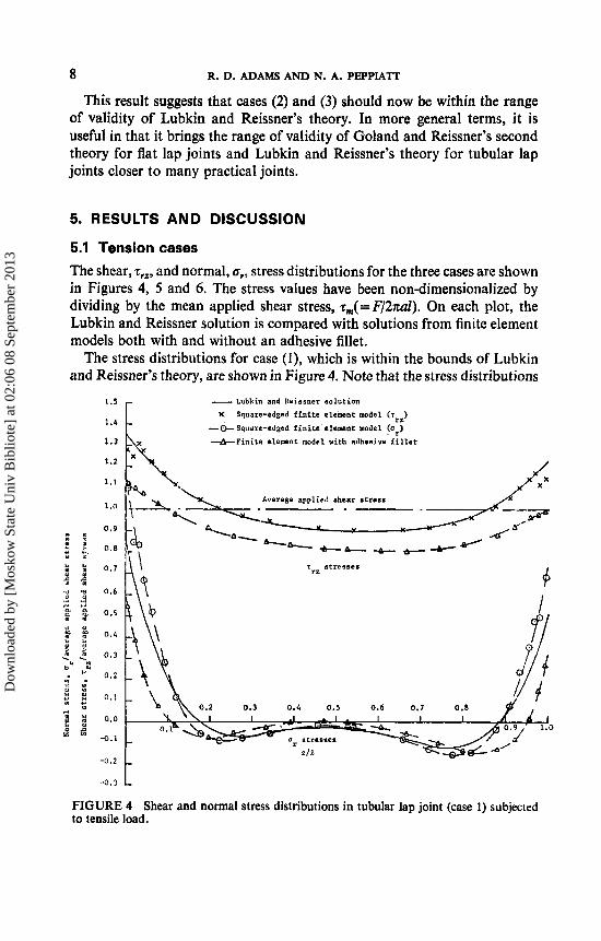
The shear, zIZ, and normal, Q,, stress distributions for the three cases are shown in Figures 4, 5 and 6. The stress values have been non-dimensionalized by dividing by the mean applied shear stress, rm(=F/2nal). On each plot, the Lubkin and Reissner solution is compared with solutions from finite element models both with and without an adhesive fillet.
The stress distributions for case (I), which is within the bounds of Lubkin and Reissner’s theory, are shown in Figure 4. Note that the stress distributions
1.5
1.4
1.3
1.2
1.1
1 .o
0.9 I S Y ,a
5 3, 0.e y I ( P
% !4 0.7
71 a 0.6 d i
g f 0.5
o u .1 .d - 3
3 5 0.4
2 3 0 . 3
0.2
* *
” U .
c” V I . 2: I0 w v )
u 1 Y :: 8 0.1
1 0.0
2 t: -0.1
-0.2
-0.3
- Lubkin and Reissner so lut ion X Squnre-edged f i n i t e element model (T?~)
-0-Square-edged f i n i t e element model (a )
+Fini te element model v i t h adhesive f i l l e t . r
Average applied shear s t r e s s
- Lubkin and Reissner so lut ion X Squnre-edged f i n i t e element model (T?~)
-0- Square-edged f i n i t e element model Fr) +Fini te element model v i t h adhesive f i l l e t
T atresses
0 . 3 0.6 0.5 0.6 0.7 0.8
t FIGURE 4 Shear and normal stress distributions in tubular lap joint (case 1) subjected to tensile load.
Dow
nloa
ded
by [
Mos
kow
Sta
te U
niv
Bib
liote
] at
02:
06 0
8 Se
ptem
ber
2013
STRESS ANALYSIS OF TUBULAR LAP JOINTS 9
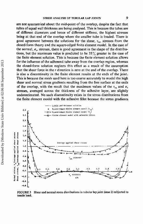
are not symmetrical about the mid-point of the overlap, despite the fact that tubes of equal wall thickness are being analysed. This is because the tubes are of different diameters and hence of different stiffness, the highest stresses being at that end of the overlap where the smaller tube is loaded. There is good agreement between the solutions for the shear, T,,, stresses from the closed-form theory and the square-edged finite element model. In the case of the normal, o,, stresses, there is good agreement in the shape of the distribu- tions, but the maximum value is predicted to be 35% greater in the case of the finite element solution. This is because the finite element solution allows for the influence of the adherend tube away from the overlap region, whereas the closed-form solution neglects this effect as a result of the assumption that the shear force in the r direction is zero at the end of the overlap. There is also a discontinuity in the finite element results at the ends of the joint. This is because the mesh used here is too coarse accurately to model the high shear and normal stress gradients resulting from the free surface at the ends of the overlap, with the result that the maximum values of the T,, and or stresses, averaged across the thickness of the adhesive layer, are slightly underestimated. No such discontinuity exists in the stress distributions from the finite element model with the adhesive fillet because the stress gradients
- lubkin and W i s s n e r so lut ion
rz) x Square-edged f i n i t e element m o l e 1 (T 2.1
2.2 f + Square-edged f i n i t e element model (ar)
4- F i n i t e element rnodel with adhesive f i l l e t
2.0
1.8
Averap applied shesr stress
a s t r e s s e s
219.
-0.6 L FIGURE 5 Shear and normal stress distributions in tubular lap joint (case 2) subjected to tensile load.
Dow
nloa
ded
by [
Mos
kow
Sta
te U
niv
Bib
liote
] at
02:
06 0
8 Se
ptem
ber
2013
10 R. D. ADAMS AND N. A. PEPPIATT
are much less. Furthermore, the maximum tensile stress is reduced to 70% and the maximum shear stress to 80% of the Lubkin and Reissner values. The area under the shear stress distribution is smaller than in the case of the square-edged solutions, because part of the load is transferred through the adhesive fillet.
In Figure 5 (case 2), there is again good agreement between the Lubkin and Reissner solutions and the square-edged finite element solutions, in spite of the fact that the case considered is outside the Goland and Reissner criterion. The presence of the adhesive fillet reduces the maximum values of z,, and u, by a greater extent, to under 50% of the Lubkin and Reissner value in the case of the a, stress, and to under 70% of the closed-form solution value in the case of the z,, stress.
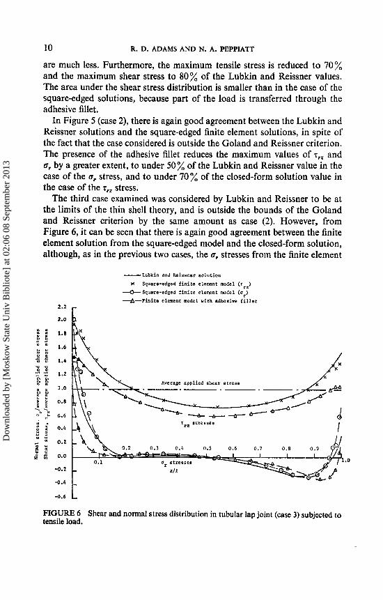
The third case examined was considered by Lubkin and Reissner to be at the limits of the thin shell theory, and is outside the bounds of the Goland and Reissner criterion by the same amount as case (2). However, from Figure 6, it can be seen that there is again good agreement between the finite element solution from the square-edged model and the closed-form solution, although, as in the previous two cases, the gr stresses from the finite element
2.2 r
2.0
-0.2
.4.4
-Lubkin and heihsner so lut ion
x Square-edged f i n i t e element modal (rrz)
--O- Square-edged f i n i t e element model Cur) +-Finice element model with adhesive f i l l e t
Average applied shear stress -. --. - . ~
T~~ s tresses
1.0
FIGURE 6 Shear and normal stress distribution in tubular lap joint (case 3) subjected to tensile load.
Dow
nloa
ded
by [
Mos
kow
Sta
te U
niv
Bib
liote
] at
02:
06 0
8 Se
ptem
ber
2013
STRESS ANALYSIS OF TUBULAR LAP JOINTS 11
solution are higher, because of the influence of the tube away from the joint. The presence of the spew fillet again reduces the maximum values of the normal, ur, and shear, Z , ~ , stresses.
The good agreement between the results from the square-edged finite element model and the closed-form theory in these three cases suggest that the results published by Lubkin and Reissner are within the bounds of validity of their theory, allowing, of course, for the limitations of the theory in its treatment of end effects, boundary conditions and neglect of the adhesive fillet. The results for cases (2) and (3) also show that the influence on the adhesive stresses of the deformations in the adherends caused by the or and r,, stresses are small and, as a result, it can be concluded that the proposed modifications to the bounds of the Goland and Reissner criterion, given in ,the previous section, are reasonable.
-- -z
\ \ \ %\\\ \ L
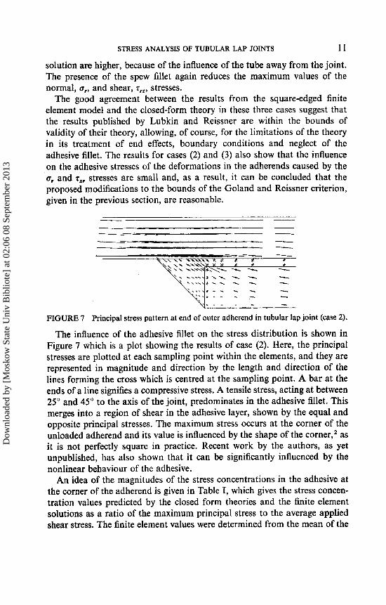
. _ _ _ - - - FIGURE 7 Principal stress pattern at end of outer adherend in tubular lap joint (case 2).
The influence of the adhesive fillet on the stress distribution is shown in Figure 7 which is a plot showing the results of case (2). Here, the principal stresses are plotted at each sampling point within the elements, and they are represented in magnitude and direction by the length and direction of the lines forming the cross which is centred at the sampling point. A bar at the ends of a line signifies a compressive stress. A tensile stress, acting at between 25" and 45" to the axis of the joint, predominates in the adhesive fillet. This merges into a region of shear in the adhesive layer, shown by the equal and opposite principal stresses. The maximum stress occurs at the corner of the unloaded adherend and its value is influenced by the shape of the corner,z as it is not perfectly square in practice. Recent work by the authors, as yet unpublished, has also shown that it can be significantly influenced by the nonlinear behaviour of the adhesive.
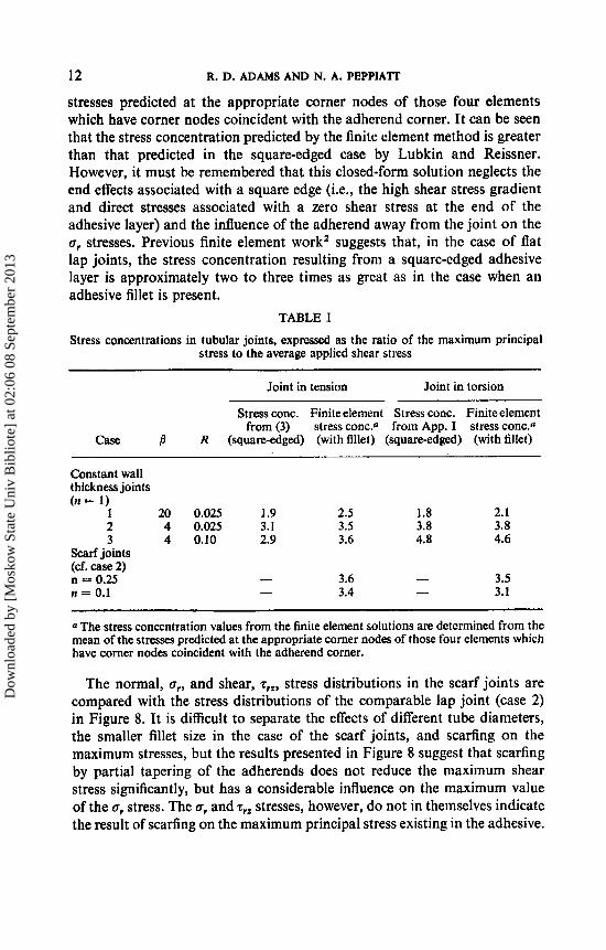
An idea of the magnitudes of the stress concentrations in the adhesive at the corner of the adherend is given in Table I, which gives the stress concen- tration values predicted by the closed form theories and the finite element solutions as a ratio of the maximum principal stress to the average applied shear stress. The finite element values were determined from the mean of the
Dow
nloa
ded
by [
Mos
kow
Sta
te U
niv
Bib
liote
] at
02:
06 0
8 Se
ptem
ber
2013
12 R. D. ADAMS AND N. A. PEPPIATT
stresses predicted at the appropriate corner nodes of those four elements which have corner nodes coincident with the adherend corner. It can be seen that the stress concentration predicted by the finite element method is greater than that predicted in the square-edged case by Lubkin and Reissner. However, it must be remembered that this closed-form solution neglects the end effects associated with a square edge (i.e., the high shear stress gradient and direct stresses associated with a zero shear stress at the end of the adhesive layer) and the influence of the adherend away from the joint on the a, stresses. Previous finite element workZ suggests that, in the case of flat lap joints, the stress concentration resulting from a square-edged adhesive layer is approximately two to three times as great as in the case when an adhesive fillet is present.
TABLE I
Stress concentrations in tubular joints, expressed as the ratio of the maximum principal stress to the average applied shear stress
Joint in tension Joint in torsion
Stress conc. Finite element Stress conc. Finiteelement from (3) stress conc.0 from App. I stress conc.a
CaSe j R (squareedged) (with fillet) (square-edged) (with fillet)
Constant wall thickness joints (n = 1)
1 20 0.025 1.9 2.5 1.8 2.1 2 4 0.025 3.1 3.5 3.8 3.8 3 4 0.10 2.9 3.6 4.8 4.6
Scarf joints (cf. case 2) n = 0.25 - 3.6 - 3.5 n = 0.1 - 3.4 - 3.1
a The stress concentration values from the finite element solutions are determined from the mean of the stresses predicted at the appropriate corner nodes of those four elements which have corner nodes coincident with the adherend corner.
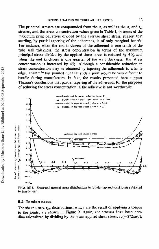
The normal, a,, and shear, z,,, stress distributions in the scarf joints are compared with the stress distributions of the comparable lap joint (case 2) in Figure 8. It is difficult to separate the effects of different tube diameters, the smaller fillet size in the case of the scarf joints, and scarfing on the maximum stresses, but the results presented in Figure 8 suggest that scarfing by partial tapering of the adherends does not reduce the maximum shear stress significantly, but has a considerable influence on the maximum value of the a, stress. The a, and z, stresses, however, do not in themselves indicate the result of scarfing on the maximum principal stress existing in the adhesive.
Dow
nloa
ded
by [
Mos
kow
Sta
te U
niv
Bib
liote
] at
02:
06 0
8 Se
ptem
ber
2013
STRESS ANALYSIS OF TUEULAR LAP JOINTS 13
The principal stresses are compounded from the a, as well as the a, and z,~ stresses, and the stress concentration values given in Table I, in terms of the maximum principal stress divided by the average shear stress, suggest that scarfing, by partial tapering of the adherends, is of only marginal benefit. For instance, when the end thickness of the adherend is one tenth of the tube wall thickness, the stress concentration in terms of the maximum principal stress divided by the applied shear stress is reduced by 4%, and when the end thickness is one quarter of the wall thickness, the stress concentration is increased by 4 %. Although a considerable reduction in stress concentration may be obtained by tapering the adherends to a knife edge, ThammI4 has pointed out that such a joint would be very difficult to handle during manufacture. In fact, the results presented here support Thamm's conclusions that partial tapering of the adherends for the purposes of reducing the stress concentration in the adhesive is not worthwhile.
_- Lubkin and Rehoner so lut ion (case 2)
--A ---Finite element model with adhesive f i l l e t --x---Partially capered scarf j o i n t n - 0.25 2.2 --4-Parcially tapered scarf j o i n t n I 0.1
1.6
1.6
1.6
1.2
1 .o
0.8
4.6
Average applied shear s t r e s s
0.4
0.2 a s t r e s s e s
0.0 1.0
-0.2
4*4 -0.6 t FIGURE 8 Shear and normal stress distributions in tubular lap and scarf joints subjected to tensile load.
5.2 Torsion cases
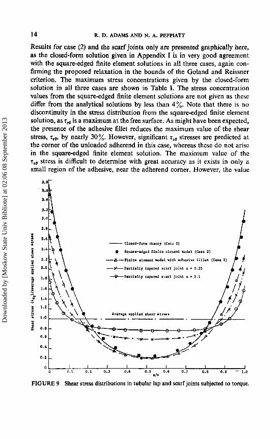
The shear stress, zr0, distributions, which are the result of applying a torque to the joints, are shown in Figure 9. Again, the stresses have been non- dirnensionalized by dividing by the mean applied shear stress, z,( = T/2na21).
Dow
nloa
ded
by [
Mos
kow
Sta
te U
niv
Bib
liote
] at
02:
06 0
8 Se
ptem
ber
2013
14 R. D. ADAMS AND N. A. PEPPIATT
Results for case (2) and the scarf joints only are presented graphically here, as the closed-form solution given in Appendix I is in very good agreement with the square-edged finite element solutions in all three cases, again con- firming the proposed relaxation in the bounds of the Goland and Reissner criterion. The maximum stress concentrations given by the closed-form solution in all three cases are shown in Table I. The stress concentration values from the square-edged finite element solutions are not given as these differ from the analytical solutions by less than 4%. Note that there is no discontinuity in the stress distribution from the square-edged finite element solution, as Z,e is a maximum at the free surface. As might have been expected, the presence of the adhesive fillet reduces the maximum value of the shear stress, Z,e, by nearly 30%. However, significant 2,e stresses are predicted at the corner of the unloaded adherend in this case, whereas these do not arise in the square-edged finite element solution. The maximum value of the Z,,q stress is difficult to determine with great accuracy as it exists in only a small region of the adhesive, near the adherend corner. However, the value
- Closed-form theory (CmE 2)
0 Square-edged f i n i t e elerwnt model (Case 2)
+-Finite element mde l with adhcaive f i l l e t (Care 2)
--%-Partially tapered scarf joint n - 0.25
&Partially tapered scarf joint n - 0.1
Average applied Dhear stress
a 0.1 0.2 0.3 0.4 0.5 0.6 0.7 0 .8 0.9 - 1.0 t i t
FIGURE 9 Shear stress distributions in tubular lap and scarF joints subjected to torque.
Dow
nloa
ded
by [
Mos
kow
Sta
te U
niv
Bib
liote
] at
02:
06 0
8 Se
ptem
ber
2013
STRESS ANALYSIS OF TUBULAR LAP JOINTS 15
determined from the mean of the stresses predicted at the appropriate corner nodes of those four elements which have corner nodes coincident with the adherend comer indicates that it is about 80% of the maximum z , ~ stress, giving a maximum principal stress concentration close to that given by the closed form theory (Table I). It can, therefore, be concluded that the influence of the adhesive fillet on the stress concentration in a tubular lap joint is far less significant when the joint is deformed by a torque than when it is loaded axially.
The z,@ distributions for the scarf joints, shown in Figure 9, indicate that scarfing is beneficial in reducing the maximum shear stress. The results given in Table I show that if the end thickness of the adherend is one quarter of the wall thickness, the stress concentration is reduced by 8 %, and if the end thickness is one tenth of the wall thickness, the stress concentration is reduced by 18%. It thus appears that partial tapering of the adherends is more beneficial when a joint is deformed by a torque than when it is loaded axially, but the reduction of maximum stress obtained is not sufficient to justify partial tapering as a worthwhile means of reducing the stress concen- tration.
6. CONCLUSIONS
Stress distributions, obtained by using axisymmetric quadratic isoparametric finite elements, have been presented for several cases of adhesive bonded tubular lap joints subjected either to an axial load or to a torque. In the axial case, they have been compared with the closed form solution of Lubkin and Reissnerj and, in the torsional case, with a closed form solution presented in Appendix I. In practice, when a joint is made, excess adhesive flows out to form an adhesive fillet, which can be approximated to a triangular shape for the purposes of finite element analysis. By considering finite element models which treat the adhesive layer as having either a square edge or an adhesive fillet at the ends of the overlap, the limitations of closed-form theories, which can only treat the adhesive as having a square edge, among other assumptions, have been examined.
In the axial load case, the stress concentrations predicted from the finite element models with the fillet have been shown to be greater than those predicted by the Lubkin and Reissner theory. This is because the closed-form solution does not evaluate the true stress concentrations, i.e. those caused by end effects. The influence of the adhesive fillet on the stress concentrations in the torsional case is shown to be less significant, as the stress concentration values from the closed form theory are of similar size to those predicted by the finite element models.
Dow
nloa
ded
by [
Mos
kow
Sta
te U
niv
Bib
liote
] at
02:
06 0
8 Se
ptem
ber
2013
16 R. D. ADAMS A N D N. A. PEPPIATT
New bounds of validity extending the range of the second criterion of Goland and Reissner, which indicates when the work of the shear and trans- verse normal stresses in the adherends can be neglected, have been proposed and confirmed by the results presented here.
Additionally, the effects of partial tapering of the adherends to form a scarf joint have been investigated. It is concluded that the reductions in stress concentration obtained with this form of joint do not make its manu- facture for this reason alone worthwhile, and in the axial case the reductions in the stress concentration were not found to be significant.
References 1 . 0. C. Zienkiewicz, The Finite Element Method in Engineering Science (McGraw-Hill,
2. R. D. Adams and N. A. Peppiatt, J. Strain Analysis 9, 185-196 (1974). 3. J. L. Lubkin and E. Reissner, Trans. ASME 78, 1213-1221 (1956). 4. 0. Volkersen, Construction Metallique, No. 4, 3-13 (1965). 5. L. P. Terekhova and I. A. Skoryi, Strength of Materials 4, 1271-1274. 6. V. M. Kukovyakin and I. A. Skoryi, Russian Engineering J. 52, No. 4 , 4 0 4 3 (1972). 7. R. S. Alwar and Y. R. Nagaraja, J. Adhesion 8, 79-92 (1976). 8. T. J. Bond, et al., J. Strain Analysis 8, 182-190 (1973). 9. R. D. Adams, J. Coppendale and N. A. Peppiatt. Submitted for publication.
London, 1971).
10. E. Hinton, F. C. Scott and R. E. Ricketts, Int. J . Numerical Methods in Engineering 9,
1 1 . M. Goland and E. Reissner, J. Applied Mechanics, Trans. ASME 66, A17427 (1944). 12. I. N. Sneddon, The stress distribution in adhesive joints in Adhesion, D. D. Eley, Ed.
(Clarendon Press, Oxford, 1961). 13. L. R. Demarkles, “Investigation of the use of a rubber analog in the study of stress
distribution in riveted and cemented joints”, Tech. Notes natn. advis. Comm. Aero- naut., Wash. 3413 (1955).
14. F. Thamm, J. Adhesion 7,301-309 (1976).
235-238 (1975).
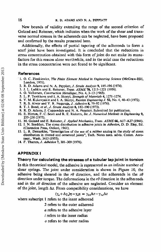
APPENDIX I Theory for calculating the stresses of a tubular lap joint in torsion In this theoretical model, the adhesive is represented as an infinite number of shear springs. The joint under consideration is shown in Figure 10, the adhesive being sheared in the r0 direction, and the adherends in the z0 direction under torque. The deformations in the re direction in the adherends and in the z0 direction of the adhesive are neglected. Consider an element of the joint, length Az. From compatibility considerations, we have
where subscript 1 refers to the inner adherend 2 refers to the outer adherend a refers to the adhesive layer i refers to the inner radius o refers to the outer radius
(Ya + A y a h - Y A = Y z 42- Y I o
Dow
nloa
ded
by [
Mos
kow
Sta
te U
niv
Bib
liote
] at
02:
06 0
8 Se
ptem
ber
2013
STRESS ANALYSIS OF TUBULAR LAP JOINTS
W
1! .J&-
In the limit
c
Dcformarions a t Plane A Deformations a t P l o w a
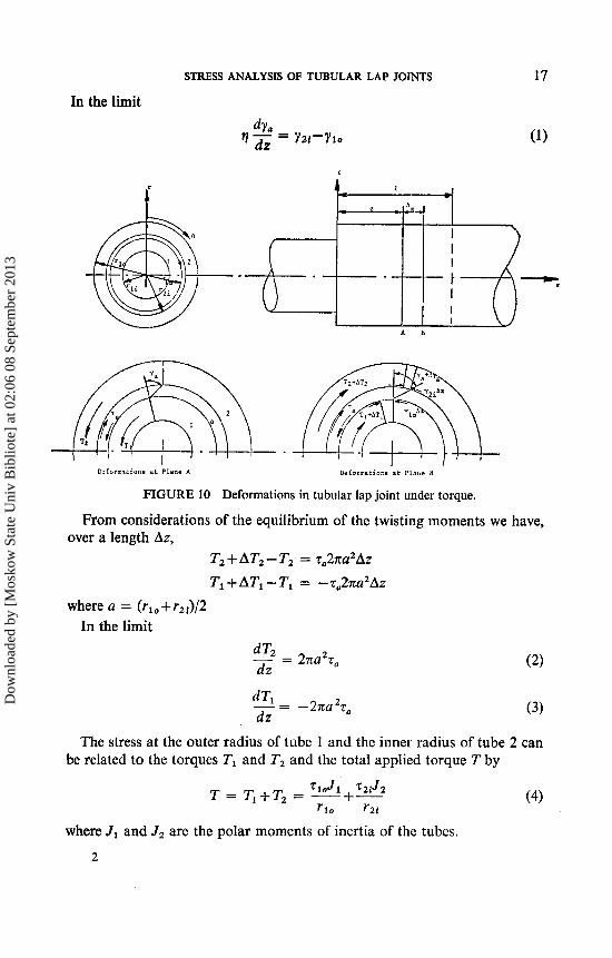
FIGURE 10 Deformations in tubular lap joint under torque.
From considerations of the equilibrium of the twisting moments we have, over a length Az,
T2 + AT2 - T2 = zu2na2Az Tl +ATl - TI = -q,2na2A2
where a = ( r lO+rz i ) /2 In the limit
The stress at the outer radius of tube 1 and the inner radius of tube 2 can be related to the torques TI and T2 and the total applied torque T by
where J1 and J2 are the polar moments of inertia of the tubes.
2
Dow
nloa
ded
by [
Mos
kow
Sta
te U
niv
Bib
liote
] at
02:
06 0
8 Se
ptem
ber
2013
18 R. D. ADAMS AND N. A. PEPPIATT
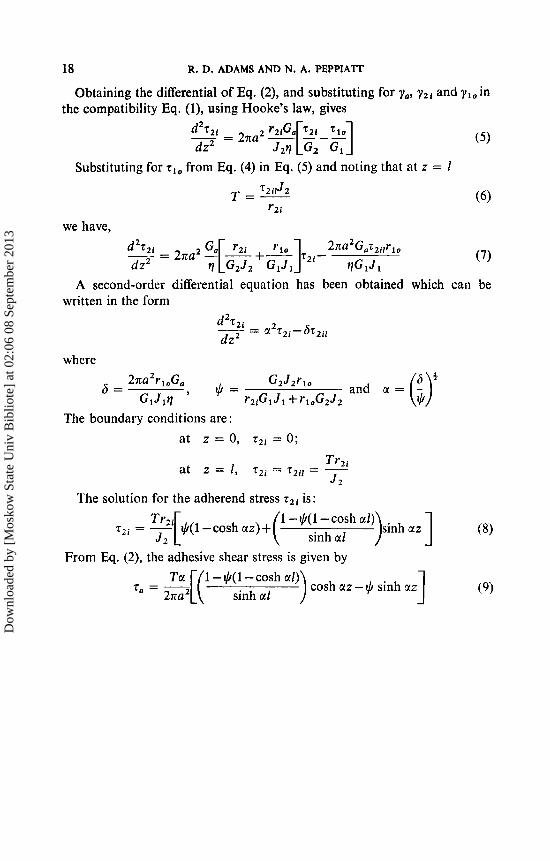
Obtaining the differential of Eq. (2), and substituting for yo, yZi and ylo in the compatibility Eq. (l), using Hooke’s law, gives
Substituting for tlo from Eq. (4) in Eq. (5 ) and noting that at z = I T=- 7 2 i l J 2
r2 i
we have,
A second-order differential equation has been obtained which can be written in the form
where 3
6 = 2rta2rloGo G2J2r10 and a = (i) GlJ l? ’ ’ = r2 iGlJ l+r loG2J2
The boundary conditions are : at z = 0, T~~ = 0;
at z = 1,
The solution for the adherend stress T~~ is:
)sinharz] (8) 1 - $( 1 -cash ~ r l )
z2 i = - Tr2i[$(l-cosh J 2 UZ)+ sinh cll From Eq. (2), the adhesive shear stress is given by
cosh c1z - $ sinh clz Ta 1-+(1 -cash ~ r l )
“ = -[( 2rta sinh ul
Dow
nloa
ded
by [
Mos
kow
Sta
te U
niv
Bib
liote
] at
02:
06 0
8 Se
ptem
ber
2013