Embed Size (px)
Citation preview
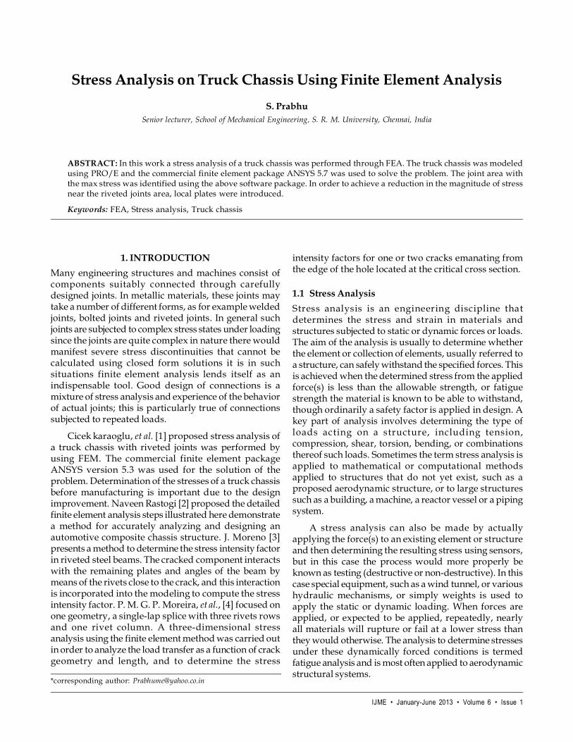
IJME • January-June 2013 • Volume 6 • Issue 1
Stress Analysis on Truck Chassis using Finite Element Analysis 55
Stress Analysis on Truck Chassis Using Finite Element Analysis
S. PrabhuSenior lecturer, School of Mechanical Engineering, S. R. M. University, Chennai, India
ABSTRACT: In this work a stress analysis of a truck chassis was performed through FEA. The truck chassis was modeledusing PRO/E and the commercial finite element package ANSYS 5.7 was used to solve the problem. The joint area withthe max stress was identified using the above software package. In order to achieve a reduction in the magnitude of stressnear the riveted joints area, local plates were introduced.
Keywords: FEA, Stress analysis, Truck chassis
*corresponding author: [email protected]
1. INTRODUCTION
Many engineering structures and machines consist ofcomponents suitably connected through carefullydesigned joints. In metallic materials, these joints maytake a number of different forms, as for example weldedjoints, bolted joints and riveted joints. In general suchjoints are subjected to complex stress states under loadingsince the joints are quite complex in nature there wouldmanifest severe stress discontinuities that cannot becalculated using closed form solutions it is in suchsituations finite element analysis lends itself as anindispensable tool. Good design of connections is amixture of stress analysis and experience of the behaviorof actual joints; this is particularly true of connectionssubjected to repeated loads.
Cicek karaoglu, et al. [1] proposed stress analysis ofa truck chassis with riveted joints was performed byusing FEM. The commercial finite element packageANSYS version 5.3 was used for the solution of theproblem. Determination of the stresses of a truck chassisbefore manufacturing is important due to the designimprovement. Naveen Rastogi [2] proposed the detailedfinite element analysis steps illustrated here demonstratea method for accurately analyzing and designing anautomotive composite chassis structure. J. Moreno [3]presents a method to determine the stress intensity factorin riveted steel beams. The cracked component interactswith the remaining plates and angles of the beam bymeans of the rivets close to the crack, and this interactionis incorporated into the modeling to compute the stressintensity factor. P. M. G. P. Moreira, et al., [4] focused onone geometry, a single-lap splice with three rivets rowsand one rivet column. A three-dimensional stressanalysis using the finite element method was carried outin order to analyze the load transfer as a function of crackgeometry and length, and to determine the stress
intensity factors for one or two cracks emanating fromthe edge of the hole located at the critical cross section.
1.1 Stress Analysis
Stress analysis is an engineering discipline thatdetermines the stress and strain in materials andstructures subjected to static or dynamic forces or loads.The aim of the analysis is usually to determine whetherthe element or collection of elements, usually referred toa structure, can safely withstand the specified forces. Thisis achieved when the determined stress from the appliedforce(s) is less than the allowable strength, or fatiguestrength the material is known to be able to withstand,though ordinarily a safety factor is applied in design. Akey part of analysis involves determining the type ofloads acting on a structure, including tension,compression, shear, torsion, bending, or combinationsthereof such loads. Sometimes the term stress analysis isapplied to mathematical or computational methodsapplied to structures that do not yet exist, such as aproposed aerodynamic structure, or to large structuressuch as a building, a machine, a reactor vessel or a pipingsystem.
A stress analysis can also be made by actuallyapplying the force(s) to an existing element or structureand then determining the resulting stress using sensors,but in this case the process would more properly beknown as testing (destructive or non-destructive). In thiscase special equipment, such as a wind tunnel, or varioushydraulic mechanisms, or simply weights is used toapply the static or dynamic loading. When forces areapplied, or expected to be applied, repeatedly, nearlyall materials will rupture or fail at a lower stress thanthey would otherwise. The analysis to determine stressesunder these dynamically forced conditions is termedfatigue analysis and is most often applied to aerodynamicstructural systems.

IJME • January-June 2013 • Volume 6 • Issue 1
56 S. Prabhu
1.2 FEA
Finite Element Analysis is a technique to simulate loadingconditions on a design and determine the design’sresponse to those conditions. The design is modeledusing discrete building blocks called elements. Eachelement has exact equations that describe how it respondsto a certain load. The sum of the response of all elementsin the model gives the total response of the design.
The finite element model, which has a finite numberof unknowns, can only approximate the response of thephysical system, which has infinite unknowns. Itdepends entirely on what we are simulation and the toolswe use for the simulation. Guidelines are providedthroughout this volume to perform various types ofanalysis.
2. TRUCK AND CHASSIS
2.1 Parts of Truck
The different parts of a truck are body, axle, chassisframe, transmission, engine and Cab.
2.1.1. Body
Specific body structures such as flatbeds, standard vans,box vans, dump-truck deep-beds, tankers, concretemixers etc. permit the economical and efficienttransportation of a wide variety of goods and materials.Connection between body and load-bearing chassisframe is effected in part by means of auxiliary frames.
consisting of side and cross members. The conventionalchassis frame, which is made of pressed steel members,can be considered structurally as grillages. The chassisframe includes cross-members located at critical stresspoints along the side members. To provide a rigid, box-like structure, the cross-members secure the two mainrails in a parallel position. The cross-members are usuallyattached to the side members by connection plates.
2.1.4. Transmission
Small trucks use the same type of transmission as almostall cars which have either an automatic transmission ora manual transmission with synchronizers. Bigger trucksoften use manual transmissions without synchronizerswhich are lighter weight although some synchronizedtransmissions have been used in larger trucks.Transmissions without synchronizers require eitherdouble clutching for each shift, (which can lead torepetitive motion injuries,) or a technique knowncolloquially as “floating,” a method of shifting whichdoesn’t use the clutch, except for starts and stops.
2.1.5. Engine
An engine is something that produces an effect from agiven input.
2.1.6. Cab
The cab is an enclosed space where the driver is seated.There are a variety of cab designs available dependingon the vehicle concept. In delivery vehicles and vans,low, convenient entrances are an advantage, whereas inlong-distance transport space and comfort are moreimportant. The type of cab configurations are cab-over-engine (COE) and cab-behind-engine.
2.2 Functions of Chassis Frame
The chassis frame is the commercial vehicle’s actual loadbearing element. It is designed as a ladder type frame,consisting of side and cross members. The choice ofprofiles decides the level of torsional stiffness.Torsionally flexible frames are preferred in medium andheavy duty trucks because they enable the suspensionto comply better with uneven terrain. Torsionally stiffframes are more suitable for smaller delivery vehiclesand vans. Critical points in the chassis-frame design arethe side-member and the cross-member junctions. Specialgusset plates or pressed cross-member sections form abroad connection basis. These junctions are riveted,bolted and welded. The conventional chassis frame,which is made of pressed steel members, can beconsidered structurally as grillages. The chassis frameincludes cross-members located at critical stress pointsalong the side members. To provide a rigid, box-likestructure, the cross-members secure the two main rails
Fig. 1: Truck Assembly
Truck assemblies1 Body, 2 Axle, 3 Chassis frame,4 Transmission, 5 Engine, 6 Cab
2.1.2. Axle
An axle is a central shaft for a rotating wheel or gear. Insome cases the axle may be fixed in position with abearing or bushing sitting inside the hole in the wheelor gear to allow the wheel or gear to rotate around theaxle. In other cases the wheel or gear may be fixed to theaxle, with bearings or bushings provided at the mountingpoints where the axle is supported.
2.1.3. Chassis Frame
The chassis frame is the commercial vehicle’s actual loadbearing element. It is designed as a ladder type frame,
IJME • January-June 2013 • Volume 6 • Issue 1
Stress Analysis on Truck Chassis using Finite Element Analysis 57
in a parallel position. The cross-members are usuallyattached to the side members by connection plates. Thejoint is riveted or bolted in trucks and is welded intrailers. When rivets are used, the holes in the chassisframe are drilled approximately 1/16 in larger than thediameter of the rivet. The rivets are then heated to anincandescent red and driven home by hydraulic or airpressure. The hot rivets conform to the shape of the holeand tighten upon cooling. An advantage of thisconnection is that it increases the chassis flexibility.Therefore, high stresses are prevented in critical area.The side- and cross-members are usually open-sectioned,because they are cheap and easily attached with rivets.
2.3 Parts of a Truck Chassis Frame
The different parts of a conventional truck chassis frameare Side members, Cross members and Gusset plates orconnection plates.
• In case of riveting, if its rivet is longer in length orirregular in hole diameter, the rivet will be fullyexpanded in the hole, then the rivet head will beformed; therefore it makes no looseness in cooling,sealing or against vibrations.
• Caulking is not necessary because no extra tensionis added to the rivet.
2.5 Loads on the Chassis Frame
All vehicles are subjected to both static and dynamicloads. Dynamic loads result from inertia forces arisingfrom driving on uneven surfaces. Loads acting in theframe cause bending or twisting of the side and the cross-members. Symmetric loads acting in the vertical directionpredominantly cause the bending in side members.Vertical loads additionally arise from lateral forces actingparallel to the frame’s plane, e.g. during cornering. Loadsacting in the plane of frame cause bending of the sidemembers and of the cross-members.
Figure 2: Parts of a Truck Chassis Frame
2.4 Riveting Operation on Truck Chassis
A monorail shall be provided above the operating placesand the trolley compiled with the balancer shall be hungdown from the monorail. The generator shall be installedat the place where it will be free from troubles andoperation. The high pressure steel pipe shall be arrangedfrom the generator to the center upper portion ofoperating position, then high pressure hose shall beconnected between the pipe end and riveter the pipingshall be fixed at near by columns or supporting beams,with clamps for protection against vibration the hoseshall be fixed with spring bands in order to flexure;however its fixing shall not affect the operation of riveter.
Advantages of Cold Riveting
• The heating equipment and its operatorare unnecessary. Handing of rivet is easy,accordingly.
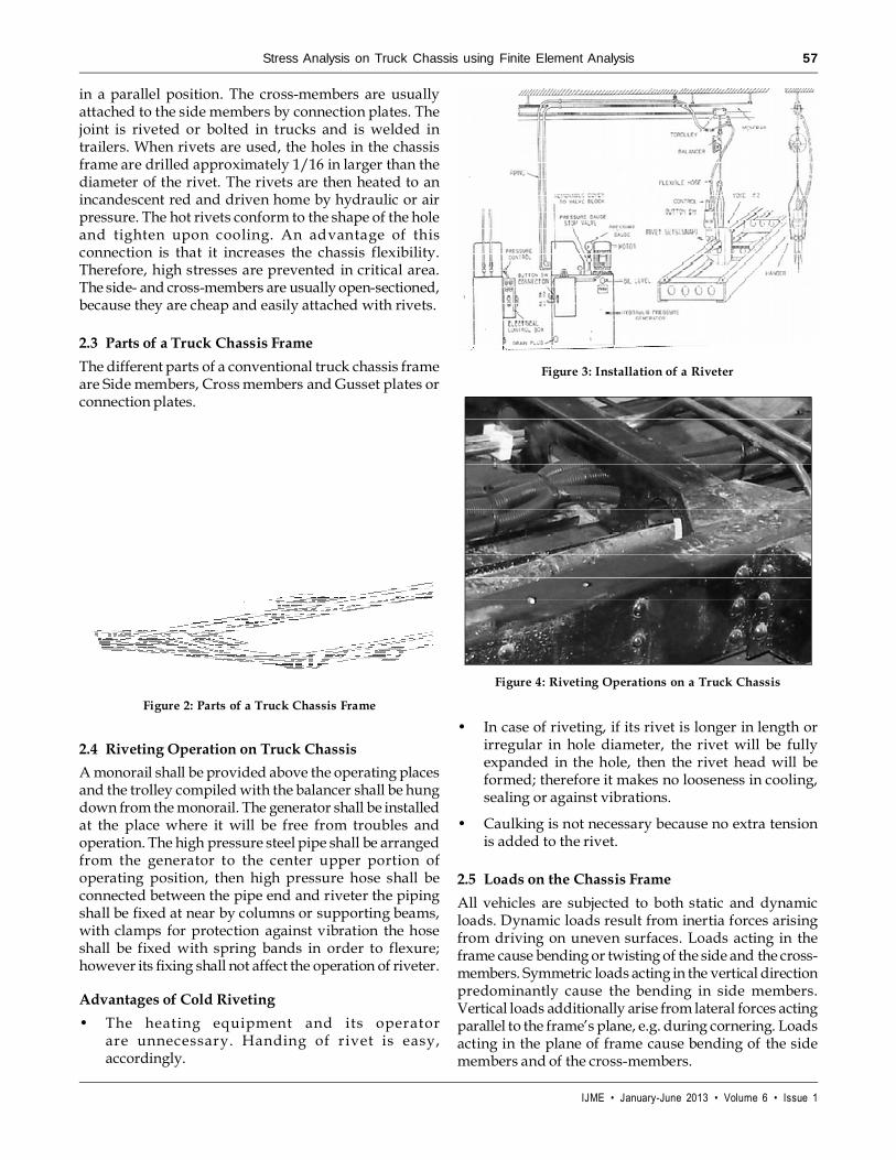
Figure 3: Installation of a Riveter
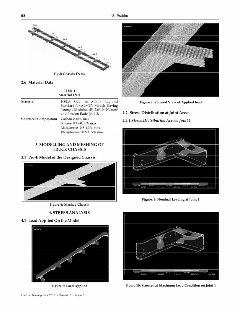
Figure 4: Riveting Operations on a Truck Chassis
IJME • January-June 2013 • Volume 6 • Issue 1
58 S. Prabhu
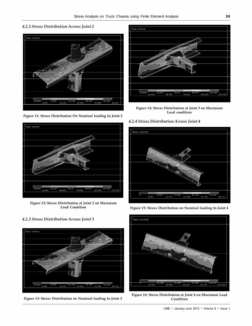
2.6 Material Data
Table 1Material Data
Material HSLA Steel to Ashok LeylandStandard for ALMDV Models HavingYoung’s Modulus (E) 2.6*105 N/mm2
and Poisson Ratio (�) 0.3.
Chemical Composition Carbon-0.16% maxSilicon- 0.15-0.35% maxManganese- 0.8-1.3% maxPhosphorus-0.02-0.05% max
3. MODELLING AND MESHING OFTRUCK CHASSIS
3.1 Pro-E Model of the Designed Chassis
4.2 Stress Distribution at Joint Areas
4.2.1 Stress Distribution Across Joint 1
Fig 5: Chassis Frame
Figure 6: Meshed Chassis
4. STRESS ANALYSIS
4.1 Load Applied On the Model
Figure 7: Load Applied
Figure 8: Zoomed View of Applied load
Figure. 9: Nominal Loading at Joint 1
Figure 10: Stresses at Maximum Load Condition on Joint 1
IJME • January-June 2013 • Volume 6 • Issue 1
Stress Analysis on Truck Chassis using Finite Element Analysis 59
4.2.2 Stress Distribution Across Joint 2
4.2.4 Stress Distribution Across Joint 4Figure 11: Stress Distribution On Nominal loading In Joint 2
Figure 12: Stress Distribution at Joint 2 on MaximumLoad Condition
4.2.3 Stress Distribution Across Joint 3
Figure 13: Stress Distribution on Nominal loading In Joint 3
Figure 14: Stress Distribution at Joint 3 on MaximumLoad condition
Figure 15: Stress Distribution on Nominal loading In Joint 4
Figure 16: Stress Distribution at Joint 4 on Maximum LoadCondition
IJME • January-June 2013 • Volume 6 • Issue 1
60 S. Prabhu
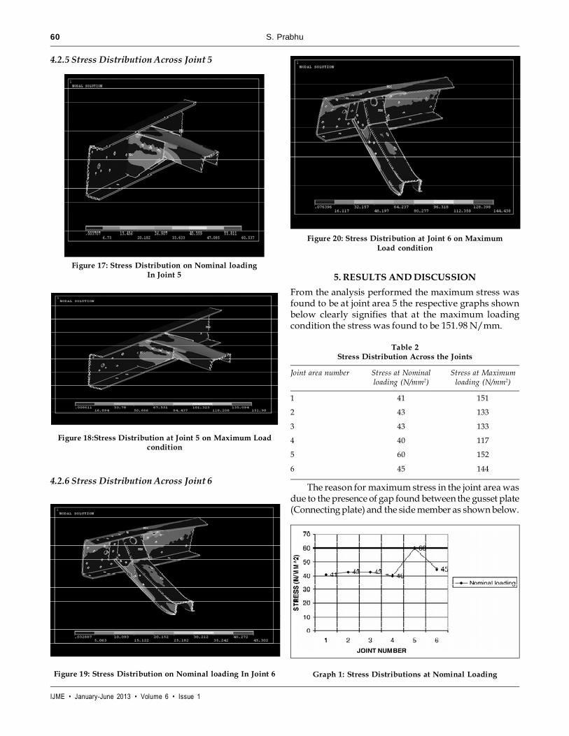
4.2.5 Stress Distribution Across Joint 5
Figure 18:Stress Distribution at Joint 5 on Maximum Loadcondition
Figure 17: Stress Distribution on Nominal loadingIn Joint 5
4.2.6 Stress Distribution Across Joint 6
Figure 19: Stress Distribution on Nominal loading In Joint 6
5. RESULTS AND DISCUSSION
From the analysis performed the maximum stress wasfound to be at joint area 5 the respective graphs shownbelow clearly signifies that at the maximum loadingcondition the stress was found to be 151.98 N/mm.
Table 2Stress Distribution Across the Joints
Joint area number Stress at Nominal Stress at Maximumloading (N/mm2) loading (N/mm2)
1 41 151
2 43 133
3 43 133
4 40 117
5 60 152
6 45 144
The reason for maximum stress in the joint area wasdue to the presence of gap found between the gusset plate(Connecting plate) and the side member as shown below.
Figure 20: Stress Distribution at Joint 6 on MaximumLoad condition
Graph 1: Stress Distributions at Nominal Loading
IJME • January-June 2013 • Volume 6 • Issue 1
Stress Analysis on Truck Chassis using Finite Element Analysis 61
CONCLUSION
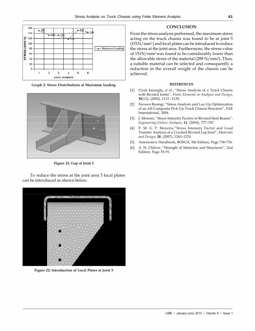
From the stress analysis performed, the maximum stressacting on the truck chassis was found to be at joint 5(151N/mm2 ) and local plates can be introduced to reducethe stress at the joint area. Furthermore, the stress valueof 151N/mm2 was found to be considerably lower thanthe allowable stress of the material (288 N/mm2). Thus,a suitable material can be selected and consequently areduction in the overall weight of the chassis can beachieved.
REFERENCES
[1] Cicek karaoglu, et al., “Stress Analysis of a Truck Chassiswith Riveted Joints”, Finite Elements in Analysis and Design,38(12), (2002), 1115 –1130.
[2] Naveen Rastogi, “Stress Analysis and Lay-Up Optimizationof an All-Composite Pick-Up Truck Chassis Structure”, SAEInternational, 2004.
[3] J. Moreno, “Stress Intensity Factors in Riveted Steel Beams”,Engineering Failure Analysis, 11, (2004), 777–787.
[4] P. M. G. P. Moreira,”Stress Intensity Factor and LoadTransfer Analysis of a Cracked Riveted Lap Joint”, Materialsand Design, 28, (2007), 1263–1270.
[5] Automotive Handbook, BOSCH, 5th Edition, Page 730-736.
[6] A. H. Chilver, “Strength of Materials and Structures”, 2ndEdition, Page 55-91.
Graph 2: Stress Distributions at Maximum loading
Figure 21: Gap at Joint 5
To reduce the stress at the joint area 5 local platescan be introduced as shown below.
Figure 22: Introduction of Local Plates at Joint 5