Embed Size (px)
Citation preview
CONCLUSIONS
I. The force-measuring pile used can be recommended for long-term measurements under various conditions of the swelling shear forces acting during the soil freezing process, on actual piles, both individually standing and also forming a part of a row, cluster, or field.
2. The outside air temperature affects the intensity of the growth in the swelling forces occurring in the soil freezing process and the maximum values of the forces.
3. In case of piles in a row, the growth in the swelling forces is more smooth and the reductions in the spring season are less intensive than in the case of individually standing piles. The values of these forces in the freezing sandy soils are considerably lower. The soil surface swelling near the piles in a row is lower than that near individual- ly standing piles.
LITERATURE CITED
i. A.V. Pataleev and G. S. Alaev, "The magnitude of the foundation swelling forces," Osn., Fundam. Mekh. Gruntov, No. 6, 24-26 (1965).
2. V.O. Orlov, Yu. A. Dubnov, and N. D. Merenkov, Swelling of Freezing Soils and its Effect on the Foundations of Structures [in Russian], Stroiizdat, Leningrad (1977).
STRIP FOUNDATIONS IN TRENCHES PUNCHED BY PLASTES USING PILE DRIVERS
V. M. Shaevich, B. I. Rubin, A. S. Krechin, and A. I. Kurolap
UDC 624. 152.6
A search for effective solutions for strip foundations, which have been carried out jointly by the State Institute for the Design and Planning of Beds and Foundations, the Kishinev Polytechnic Institute and by the former Ministry of Agricultural Construction, Moldavian SSR, has led to the use of foundations installed in trenches punched by plates using pile drivers mounted on truck and tractor bases.
The plates are elongated in plan, and their width along the top is sufficient for sup- porting the walls of a building. Individual trenches into whose bed crushed stone is tamped when necessary, are punched using this plate. A continuous trench in which the strip founda- tion is concreted is formed by joining the pits. An increase in foundation bearing capacity is achieved by the installation of a combined trench with an expended bed, when a columnar trench is punched through the pit and crushed stone is tamped into its base. Various sizes of columnar and strip plates have been developed and fabricated for punching trenches, and alternations, which make it possible to increase the excursion of the hammer and gravel beyond the limits of the guide post, and, consequently, to place the plate being driven into the ground not only along the longitudinal axis of the driver, bit also perpendicular to it, have been introduced (Fig. I). The design of the pile-cable attachement was also changed; this made it possible to use this new design independently to remove the plates from the ground with a force to 150 kN.
Studies of the performance of strip foundations in trenches punched by plates using pile-driving rigs were conducted at an experimental proving ground in Kishinev (site No. i) and in the construction of a school in the settlement of Grigoriopol' (site No. 2). We tested i0 segments of strip foundation, which were concreted in individual trenches 1.5 m long and which had a trapezoidal cross section with an upper base of 0.5 m and lower base of 0.2 m, at the No. 1 site. The height of five of these segments was 0.5 m, and that of the remaining segments 0.8 m. Foundations of each type were fabricated both without an expanded section and with an expanded section formed from 0.05, 0.15, 0.2, and 0.25 m 3 of crushed stone tamped
State Institute for the Design and Planning of Beds and Foundations. Kishinev Polytechnic Institute. State Institute for the Design and Planningof Agricultural Construction, Moldavian SSR. Giproplodoovoshchprom. Translated from Osnovaniya, Fundamenty i Mekhanika Gruntov, No. 6, pp. 19-22, November-December, 1988.
554 0038-0741/88/2506-0554512.50 © 1989 Plenum Publishing Corporation
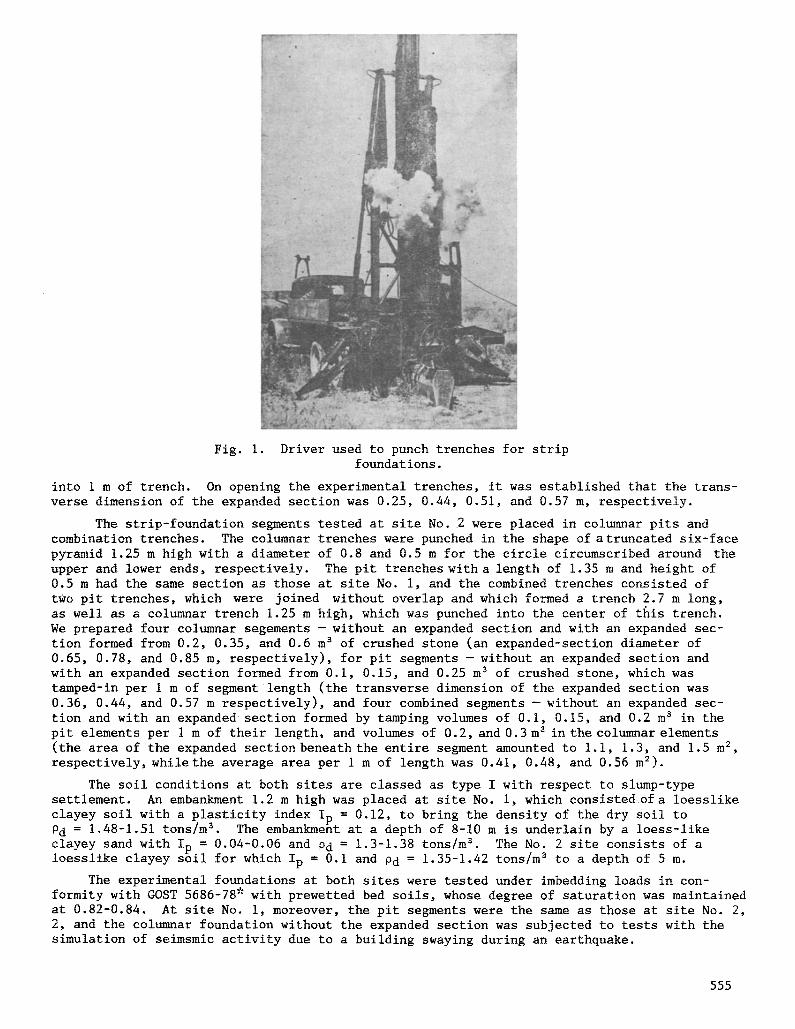
Fig. i. Driver used to punch trenches for strip foundations.
into 1 m of trench. On opening the experimental trenches, it was established that the trans- verse dimension of the expanded section was 0.25, 0.44, 0.51, and 0.57 m, respectively.
The strip-foundation segments tested at site No. 2 were placed in columnar pits and combination trenches. The columnar trenches were punched in the shape of atruncated six-face pyramid 1.25 m high with a diameter of 0.8 and 0.5 m for the circle circumscribed around the upper and lower ends, respectively. The pit trenches with a length of 1.35 m and height of 0.5 m had the same section as those at site No. i, and the combined trenches consisted of two pit trenches, which were joined without overlap and which formed a trench 2.7 m long, as well as a columnar trench 1.25 m high, which was punched into the center of this trench. We prepared four columnar segements - without an expanded section and with an expanded sec- tion formed from 0.2, 0.35, and 0.6 m s of crushed stone (an expanded-section diameter of 0.65, 0.78, and 0.85 m, respectively), for pit segments - without an expanded section and with an expanded section formed from 0.i, 0.15, and 0.25 m 3 of crushed stone, which was tamped-in per i m of segment length (the transverse dimension of the expanded section was 0.36, 0.44, and 0.57 m respectively), and four combined segments - without an expanded sec- tion and with an expanded section formed by tamping volumes of 0.i, 0.15, and 0.2 m s in the pit elements per i m of their length, and volumes of 0.2, and 0.3 m a in the columnar elements (the area of the expanded section beneath the entire segment amounted to i.i, 1.3, and 1.5 m 2, respectively, while the average area per 1 m of length was 0.41, 0.48, and 0.56 m=).
The soil conditions at both sites are classed as type I with respect to slump-type settlement. An embankment 1.2 m high was placed at site No. I, which consisted of a loesslike clayey soil with a plasticity index Ip = 0.12, to bring the density of the dry soil to Pd = 1.48-1.51 tons/m s . The embankment at a depth of 8-10 m is underlain by a loess-like clayey sand with Ip = 0.04-0.06 and Pd = 1.3-1.38 tons/m s The No. 2 site consists of a loesslike clayey soil for which Ip = 0.i and Pd = 1.35-1.42 tons/m 3 to a depth of 5 m.
The experimental foundations at both sites were tested under imbedding loads in con- formity with GOST 5686-78* with prewetted bed soils, whose degree of saturation was maintained at 0.82-0.84. At site No. I, moreover, the pit segments were the same as those at site No. 2, 2, and the columnar foundation without the expanded section was subjected to tests with the simulation of seimsmic activity due to a building swaying during an earthquake.
555
TABLE 1
Site No. Foundation
0.5-m high pit 0.8-m high pit Columnar Pit Combined
R e s i s t a n c e values (kN/ m ~ ) f o r ~ t t l e m e n t o f
J u
f R
105 612
lOO 640
45 265 80 325 72 375
The tests conducted under the embedding loads indicated that the relationship between settlements and these loads is nonlinear for all segments and has a "soft" characteristic common for these tests. It was established that these relationships can be described rather accurately, having represented the interaction between the foundation and bed in the form of a model [i] in which the lateral resistance of the soil is piecewise-linear with two seg- ments, while the soil resistance below the expanded section or the lower end of the founda- tion is linear. The test results made it possible to determine the values of all parameters of this model for the experimental foundations at both sites, with whose use it is possible to determine separately the specific values of the soil's resistance at the lateral surface and below the lower end of the foundation (expanded section), which corresponds to the bear- ing capacity; these values are of greatest interest for practical calculations. The bearing capacity of the foundations in the tamped trenches with an expanded bed is determined from the test results for settlements amounting ot 0.3 of the average limiting building settlements [2], i.e., 30 mm for buildings with bearing walls. Specific soil-resistance value f of the lateral surface and R beneath the lower end (expanded section) of the experimental founda- tions when their settlements are 30 mm are presented in Table i from which it is apparent that the f and R values for a strip foundation are 1.7 and 1.3 times higher, respectively, than those for a columnar foundation. This is apparently explained by the differences in the stressed state of the soil during plane and three-dimensional deformation during both the driving of the plate and loading of the foundation. The embedment resistance depends heavily on the soil conditions: the f and R values for the No. 1 site are, on average, 1.35 and 1.8 times higher than those for the No. 2 site.
Tests of the pit and columnar foundations without the expanded section at the No.l site with a seismic event simulated as the earthquake-induced swaying of a building were conducted using a direct-action vibrator placed on the ground and rigidly connected to the experimental foundation. The moment of the vibrator's eccentrics is varied in steps and can be assigned the following values: 49, 96, 147, and 196 N'm. The rotation frequency of the eccentrics is evenly regulated to 1500 rpm. The tests were conducted in accordance with the method de- veloped by ll'ichev et al. [i]. The experimental foundation was loaded in steps by an embed- ding load, just as during the static tests, to a settlement of 30 mm, after the vibrator, which had been adjusted for the required eccentric moments and frequency, was engaged. The vibrator was operated for a period of 30 sec. In the testing process, a constant embedding load was maintained, and the vibration amplitudes and frequencies of the foundation, as well as its dynamic settlement were measured. The seismic coefficient 7£ 9 of the operating condi- tions, which takes into account the reduction in the bearing capacity of the experimental foundation under a lateral seismic load due the swaying building was established from test data as the ratio of the dynamic settlement ot its sum with the static settlement. This coefficient was used as a function of the dynamic reaction of the bed, which was determined in conformity with [3].
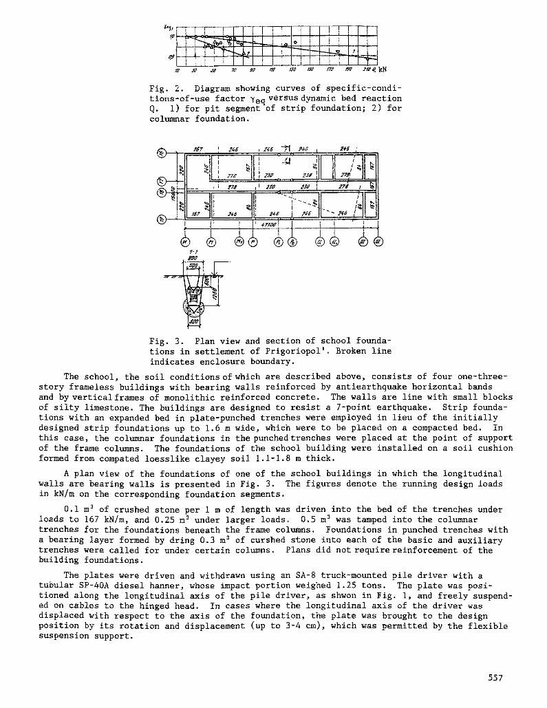
The test results indicate that 7£q decreases linearly with increasing dynamic reaction (Fig. 2), never going below 0.9 when its values correspond to the maximum possible lateral seismic load on the strip and columnar foundations with the same bearing capacity under embedment as for the experimental foundations. These data suggest the extremely high earth- quake resistance of foundations in plate-punched trenches. For the columnar foundations in the tamped trenches, the X£q values established by Krutov et al. [4] can be reduced to 0.65- 0.7 for characteristic lateral seismic loads.
Strip foundations in plate-punched trenches have been introduced to seimic regions of Moldavia in the construction of a school in the settlement of Prigoriopol' and in two 18-unit apartment buildings in Kotovsk.
556
r,,,~ _ I I t I I I
r /0 J? ~ 70 gG I¢0 I{0 /Sg /Fg /~g 2/g ~, kN
Fig. 2. Diagram showing curves of specific-condi- tions-of-use factor 7eq versus dynamic bed reaction Q. i) for pit segment of strip foundation; 2) for columnar foundation.
2 ~
~ 0
, g Fig. 3. Plan view and section of school founda- tions in settlement of Prigoriopol'. Broken line indicates enclosure boundary.
The school, the soil conditions of which are described above, consists of four one-three- story frameless buildings with bearing walls reinforced by antiearthquake horizontal bands and by vertical frames of monolithic reinforced concrete. The walls are line with small blocks of silty limestone. The buildings are designed to resist a 7-point earthquake. Strip founda- tions with an expanded bed in plate-punched trenches were employed in lieu of the initially designed strip foundations up to 1.6 m wide, which were to be placed on a compacted bed. In this case, the columnar foundations in the punched trenches were placed at the point of support of the frame columns. The foundations of the school building were installed on a soil cushion formed from compared loesslike clayey soil 1.1-1.8 m thick.
A plan view of the foundations of one of the school buildings in which the longitudinal walls are bearing walls is presented in Fig. 3. The figures denote the running design loads in kN/m on the corresponding foundation segments.
0.i m 3 of crushed stone per 1 m of length was driven into the bed of the trenches under loads to 167 kN/m, and 0.25 m 3 under larger loads. 0.5 m 3 was tamped into the columnar trenches for the foundations beneath the frame columns. Foundations in punched trenches with a bearing layer formed by dring 0.3 m 3 of curshed stone into each of the basic and auxiliary trenches were called for under certain columns. Plans did not require reinforcement of the building foundations.
The plates were driven and withdrawn using an SA-8 truck-mounted pile driver with a tubular SP-40A diesel harmer, whose impact portion weighed 1.25 tons. The plate was posi- tioned along the longitudinal axis of the pile driver, as shwon in Fig. I, and freely suspend- ed on cables to the hinged head. In cases where the longitudinal axis of the driver was displaced with respect to the axis of the foundation, the plate was brought to the design position by its rotation and displacement (up to 3-4 cm), which was permitted by the flexible suspension support.
557
The design called for the foundations of each school building to be partitioned into enclosures to permit the punching of trenches and their concreting within the limits of each enclosure during a single shift and to preclude jointing of adjacent foundation seg- ments at points of intersection after a break in concreting. Considering the data of the experimental studies, which had made it possible to determine the productivity of the pile driver in punching trenches, foundations shown inwith an overall length of 26-28 m were in- cluded in the enclosures with allowance for the time required for concreting. Thus. the building foundations shown in Fig. 3 wee partitioned, as shown by the dotted hines, into i0 of the these enclosures. During the work, however, it was ascertained that 35-40 m of foundation could be fabricatd per shiftwith the nonstop placment of concrete.
It was necessary to conduct the work within the limits of an enclosure to ensure the wall stability of the finished trenches during the punching of tenches perpendicular to the latter at points of intersection, and also in case the rig was forced onto them. For this purpose, we fabricated a metallic form of trapezoidal cross section 1 m long, which was formed from a thin-wall sheet attached to the frame by angle brackets with base dimensions 1-1.5 cm smaller than those of the plate. The were placed manually into the punched trenches at points where there was a risk of wall collapse.
When work involving installation of the strip trenches had been completed within the limits an enclosure, a new plate was suspended from the pile driver; using this plate, a columnar trench was punched through the strip trench, not necessarily at the point of juncture.
As a result of implementation of the proposed method of installing foundations, we saved 6.2 tons of reinforcement, 15.2 tons of cement, 2.2 m 3 of lumber, 408 man-days of labor and 8800 rubles of funding in constructing the school; this amounts to 25% of the overall expenditures for the initial design.
In constructing the two three-story 18-unit apartment houses in Kotovsk, strip founda- tions in plate-punched trenches were used in lieu of pile foundations formed from driven 30 × 30-cm piles 8 and ii m iong. The surface at the site consists of loesslike sandy loams 2-4 m thick, which are prone to slump-type settlement and which are underlain by porous fine and silty sands of medium density. Hard clays, which were to support the lower ends of the piles, are located at a depth of 7-10 m. The groundwater table is situated at a depth of 103 m from the surface. The buildings are designed to resist an 8-point earthquake.
It was specified tht the walls be stacked from small blocks of silty limestone. The transverse walls are bearing walls. Monolithic reinforced-concrete bands around the entire walls at the level of the ceilings and roof serve as antiearthquake measures. A soil cushion formed form loesslike sandy foams 1-1.5 m thick was placed beneath the building. The runn- ing design load on the foundation is 66-228 kN/m. The trenches were punched by a strip plate 1.5 m long, and 0.6 and 0.35 m wide at the top and bottom using an SP-67 pile driver mounted on a tractor. The foundation was not strengthened with columnar elements. Foundations sub- jected to loads of 166 and 228 kN/m were installed with an expanded section formed from 0.i m 3 and 0.2 m 3 of crushed stone, respectively per i m of length. The foundations of each build- ing were partitioned into five enclosures to carry out the work.
The saving generated from implenentation of the proposed method at both apartment houses amounted to 35% of the overall expenditures allotted for the initial desing, the consumption of reinforcement, cement, and wood were reduced by 17.5 tons, 47,8 tons, and 2.5 m ~, respec- tively, labor outlayes by 650 man-days, and funding by 12,200 rubles.
I.
2.
3.
4.
LITERATURE CITED
V. A. Ii'ichev, Yu. V. Mongolov, and V. M. Shaevich, Pile Foundations in Seismic Regions [in Russian], Stroiizdat, Moscow (1983). Guidelines for the Design and Installation of Foundations in Tamped Trenches [in Rus- sian], Stroiizdat, Moscow (1981). A. V. Anik'ev, V. V. Starodvorskii, and V. M. Shaevich,"On a specific conditions-of-use factor that accounts for lateral dynamic effects," Dynamics of Beds, Foundations, and Underground Structures: Theses of Papers Presented at the Sixth All-Union Conference [in Russian], Leningrad (1985), pp. 188-190. V. I. Krutov, V. V. Starodvorskii, and V. M. Shaevich, "Installation of foundations in tamped trenches for projects involving agricultural-industrial complexes in seismic regions," Osn., Fundam. Mekh. Gruntov, No. 5, 8-11 (1983).
558


![PredictionofPoreSizeCharacteristicsofNeedle-Punched ...downloads.hindawi.com/journals/ace/2020/8839519.pdfneedle-punched geotextiles tested by Wu and Hong [24] decrease with uniaxial](https://img.pdfslide.net/doc/110x75/5f98c7e15b3a445a3108bdae/predictionofporesizecharacteristicsofneedle-punched-needle-punched-geotextiles.jpg)