Embed Size (px)
Citation preview
SASTECH Journal 19 Volume 9, Issue 2, September 2010
STRUCTURAL ANALYSIS OF FIBER- FILLED PLASTICS WITH MOULDING PROCESS INDUCED ANISOTROPY
P. Satheesh Kumar1, S. Srikari2, N. S. Mahesh3, S. Reddy4
1Student, M. Sc. [Engg.], 2Professor, 3Professor and Center Manager (AMT and EMM), M.S. Ramaiah School of Advanced Studies, Bangalore 560 054
4
Keywords: Fiber Filled Plastic, Fiber Orientation, Anisotropic, Orthotropic, Moldflow, ANSYS
Senior Analyst, Schneider Electric India Pvt. Ltd.
Abstract Thermoplastics have many advantages over metal parts, including lower mass and ease of fabrication. To further
improve their elastic modulus, creep resistance, and dimensional stability, short fibers are added to polymers. Such composites find widespread use because they can be processed with techniques used for unfilled polymers, provided the fiber length is below a certain limit. However, the application of fiber-filled thermoplastic materials has been limited in many cases by the inability to accurately predict performance and durability.
In this work, structural analysis capability of ANSYS is used in conjunction with flow simulation capability of Moldflow. The Moldflow fiber orientation simulation model allows significantly improved prediction of orientation of fibers in a molded component over a range of polymer materials and fiber contents. The ANSYS interface for Moldflow is used to translate this information to an input file for structural analysis using ANSYS. With effect of fiber orientation incorporated in the material properties, results of this structural analysis provide more realistic valuse of deformation and stresses in the formed part.
Linear orthotropic analysis is carried out on ash tray door component by coupling Moldflow with ANSYS. A comparison is made between the results from linear isotropic and linear orthotropic analysis with different gating systems to understand the effect of these parameters on the mechanical performance of the part. Simulation results are able to predict the observed mechanical behaviour of short-fiber filled plastic components when the anisotropy of the material is taken into consideration. Traditional approach of treating the material property as isotropy overestimates the stiffness of the part. Also, modelling of flow is able to quantify the anisotropy generated in the part during its fabrication process.
Abbreviations CAD Computer-Aided Design CAE Computer-Aided Engineering
1. INTRODUCTION The automotive industry is on the brink of a
revolution, and the plastics industry is poised to play a major role. New technologies are enabling improvements in safety, comfort and savings in energy. Lightweight plastics allow automotive designers and engineers the freedom to deliver innovative concepts cost effectively. From an aesthetic perspective, plastics and plastic composites offer the automotive designers distinct advantages in many applications. Plastics provide versatile designs in electrical, electronic, and lighting applications, further enhancing new styling opportunities. Versatility is core to plastics' beauty, allowing for efficient design through consolidation of parts and their modularity, reducing parts manufacturing costs and enhancing vehicle affordability [1].
Short-fiber reinforced composites are widely used for their high strength to weight ratios and remarkably enhanced physical properties compared with pure polymer products. Compression molding, extrusion and injection molding are some of the processes often used for fabricating components of short-fiber reinforced composites. The fibers are suspended in the polymer matrix, and during manufacturing process orient themselves in response to the interactions among kinematics of the flow, other neighboring fibers and mold cavity. Fiber reinforced composites typically show anisotropic mechanical, thermal and rheological properties. Therefore, prediction of fiber orientation
during the transient mold filling is important for the prediction of such anisotropic properties of final plastic part.
One of the complicating factors for injection-molded plastic parts is the change in the properties of plastics during the manufacturing process. While this is not a problem in and of itself, problems can arise if the structural analyses are based on generic material data that does not accurately represent the actual properties of the molded part. This can lead to over engineering of components, resulting in increased costs and material usage, or under-engineering, which can result in premature failure of parts.
When glass or carbon fibers are added to plastics, the elastic modulus can increase significantly with a negligible effect on part weight. This combination of low weight and high stiffness makes fiber-filled plastics ideal for high-performance applications. The orientation direction and the degree of orientation of the fibers determine the mechanical properties of the molded part. The material will have higher strength in the direction in which majority of the fibers are aligned, but will be relatively weak in the direction perpendicular to it (across the fibers). In areas where fibers are randomly oriented, the material will not achieve maximum strength and the material will exhibit isotropic behaviour.
During injection molding process, the fibers in the plastic melt will orient in different directions under the influence of shear forces resulting from flow patterns. This will result in material properties being different at different locations of the part.
SASTECH Journal 20 Volume 9, Issue 2, September 2010
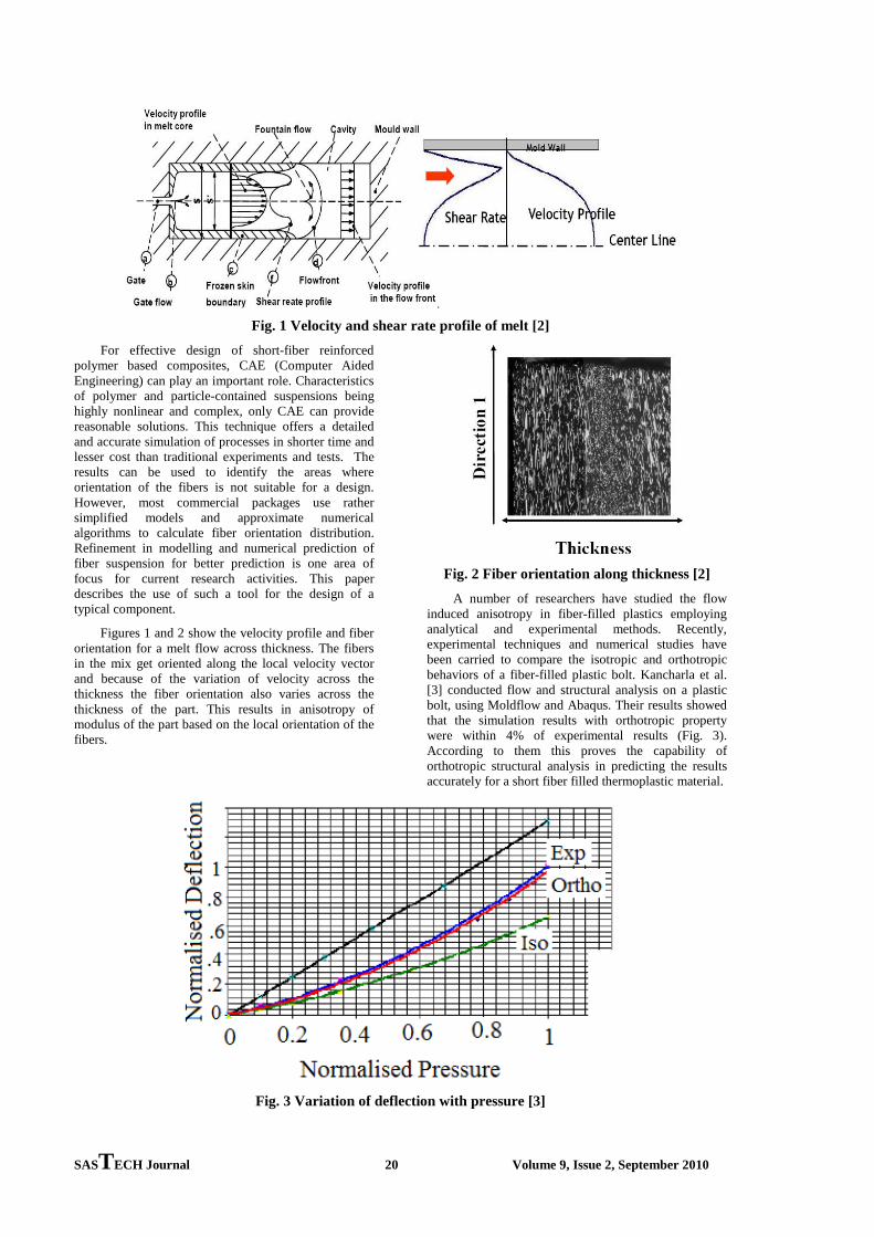
Fig. 1 Velocity and shear rate profile of melt [2] For effective design of short-fiber reinforced
polymer based composites, CAE (Computer Aided Engineering) can play an important role. Characteristics of polymer and particle-contained suspensions being highly nonlinear and complex, only CAE can provide reasonable solutions. This technique offers a detailed and accurate simulation of processes in shorter time and lesser cost than traditional experiments and tests. The results can be used to identify the areas where orientation of the fibers is not suitable for a design. However, most commercial packages use rather simplified models and approximate numerical algorithms to calculate fiber orientation distribution. Refinement in modelling and numerical prediction of fiber suspension for better prediction is one area of focus for current research activities. This paper describes the use of such a tool for the design of a typical component.
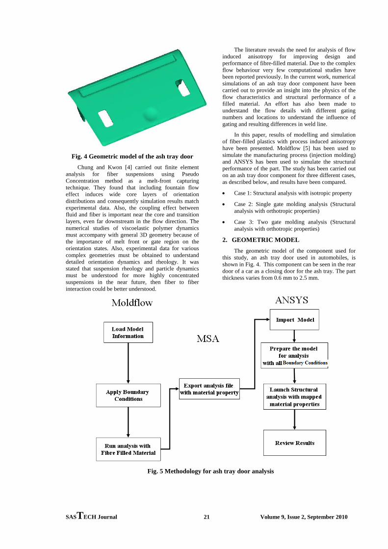
Figures 1 and 2 show the velocity profile and fiber orientation for a melt flow across thickness. The fibers in the mix get oriented along the local velocity vector and because of the variation of velocity across the thickness the fiber orientation also varies across the thickness of the part. This results in anisotropy of modulus of the part based on the local orientation of the fibers.
Fig. 2 Fiber orientation along thickness [2] A number of researchers have studied the flow
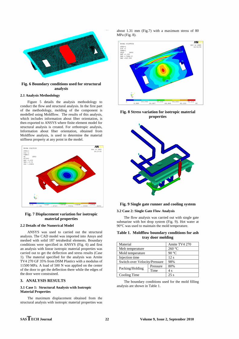
induced anisotropy in fiber-filled plastics employing analytical and experimental methods. Recently, experimental techniques and numerical studies have been carried to compare the isotropic and orthotropic behaviors of a fiber-filled plastic bolt. Kancharla et al. [3] conducted flow and structural analysis on a plastic bolt, using Moldflow and Abaqus. Their results showed that the simulation results with orthotropic property were within 4% of experimental results (Fig. 3). According to them this proves the capability of orthotropic structural analysis in predicting the results accurately for a short fiber filled thermoplastic material.
Fig. 3 Variation of deflection with pressure [3]
SASTECH Journal 21 Volume 9, Issue 2, September 2010
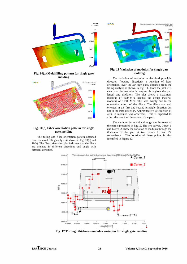
Fig. 4 Geometric model of the ash tray door Chung and Kwon [4] carried out finite element
analysis for fiber suspensions using Pseudo Concentration method as a melt-front capturing technique. They found that including fountain flow effect induces wide core layers of orientation distributions and consequently simulation results match experimental data. Also, the coupling effect between fluid and fiber is important near the core and transition layers, even far downstream in the flow direction. The numerical studies of viscoelastic polymer dynamics must accompany with general 3D geometry because of the importance of melt front or gate region on the orientation states. Also, experimental data for various complex geometries must be obtained to understand detailed orientation dynamics and rheology. It was stated that suspension rheology and particle dynamics must be understood for more highly concentrated suspensions in the near future, then fiber to fiber interaction could be better understood.
The literature reveals the need for analysis of flow induced anisotropy for improving design and performance of fibre-filled material. Due to the complex flow behaviour very few computational studies have been reported previously. In the current work, numerical simulations of an ash tray door component have been carried out to provide an insight into the physics of the flow characteristics and structural performance of a filled material. An effort has also been made to understand the flow details with different gating numbers and locations to understand the influence of gating and resulting differences in weld line.
In this paper, results of modelling and simulation of fiber-filled plastics with process induced anisotropy have been presented. Moldflow [5] has been used to simulate the manufacturing process (injection molding) and ANSYS has been used to simulate the structural performance of the part. The study has been carried out on an ash tray door component for three different cases, as described below, and results have been compared.
• Case 1: Structural analysis with isotropic property
• Case 2: Single gate molding analysis (Structural analysis with orthotropic properties)
• Case 3: Two gate molding analysis (Structural analysis with orthotropic properties)
2. GEOMETRIC MODEL The geometric model of the component used for
this study, an ash tray door used in automobiles, is shown in Fig. 4. This component can be seen in the rear door of a car as a closing door for the ash tray. The part thickness varies from 0.6 mm to 2.5 mm.
Fig. 5 Methodology for ash tray door analysis
SASTECH Journal 22 Volume 9, Issue 2, September 2010
Fig. 6 Boundary conditions used for structural analysis
2.1 Analysis Methodology
Figure 5 details the analysis methodology to conduct the flow and structural analysis. In the first part of the methodology, molding of the component is modelled using Moldflow. The results of this analysis, which includes information about fiber orientation, is then exported to ANSYS where finite element model for structural analysis is created. For orthotropic analysis, Information about fiber orientation, obtained from Moldflow analysis, is used to determine the material stiffness property at any point in the model.
Fig. 7 Displacement variation for isotropic material properties
2.2 Details of the Numerical Model
ANSYS was used to carried out the structural analysis. The CAD model was imported into Ansys and meshed with solid 187 tetrahedral elements. Boundary conditions were specified in ANSYS (Fig. 6) and first an analysis with linear isotropic material properties was carried out to get the deflection and stress results (Case 1). The material specified for the analysis was Arnite TV4 270 GF 35% from DSM Plastics with a modulus of 11500 MPa. A load of 500 N was applied on the center of the door to get the deflection there while the edges of the door were constrained.
3. ANALYSIS RESULTS
3.1 Case 1: Structural Analysis with Isotropic Material Properties
The maximum displacement obtained from the structural analysis with isotropic material properties was
about 1.31 mm (Fig.7) with a maximum stress of 80 MPa (Fig. 8).
Fig. 8 Stress variation for isotropic material properties
Fig. 9 Single gate runner and cooling system
3.2 Case 2: Single Gate Flow Analysis
The flow analysis was carried out with single gate submarine with hot drop system (Fig. 9). Hot water at 90°C was used to maintain the mold temperature.
Table 1. Moldflow boundary conditions for ash tray door molding
Material Amite TV4 270 Melt temperature 260 °C Mold temperature 90 °C Injection time 12 s Switch-over Velocity/Pressure 98%
Packing/Holding Pressure 80% Time 4 s
Cooling Time 25 s
The boundary conditions used for the mold filling analysis are shown in Table 1.
SASTECH Journal 23 Volume 9, Issue 2, September 2010
Fig. 10(a) Mold filling pattern for single gate molding
Fig. 10(b) Fiber orientation pattern for single gate molding
The filling and fiber orientation pattern obtained from the mold filling analysis is shown in Fig. 10(a) and 10(b). The fiber orientation plot indicates that the fibers are oriented in different directions and angle with different densities.
Fig. 11 Variation of modulus for single gate molding
The variation of modulus in the third principle direction (loading direction), a function of fiber orientation, over the ash tray door, obtained from the filling analysis is shown in Fig. 11. From the plot it is clear that the modulus is varying throughout the part length and thickness. The plot shows a maximum modulus of 6024 MPa against the actual material modulus of 11500 MPa. This was mainly due to the orientation effect of the fibers. The fibers are well oriented in the first and second principle direction but not in the third direction. Approximately, a reduction of 45% in modulus was observed. This is expected to affect the structural behaviour of the part.
The variation in modulus through the thickness of the part is presented in Fig.12. The two curves, Curve_1 and Curve_2, show the variation of modulus through the thickness of the part at two points P1 and P2 respectively. The location of these points is also identified in Figure 12.
Fig. 12 Through thickness modulus variation for single gate molding
SASTECH Journal 24 Volume 9, Issue 2, September 2010
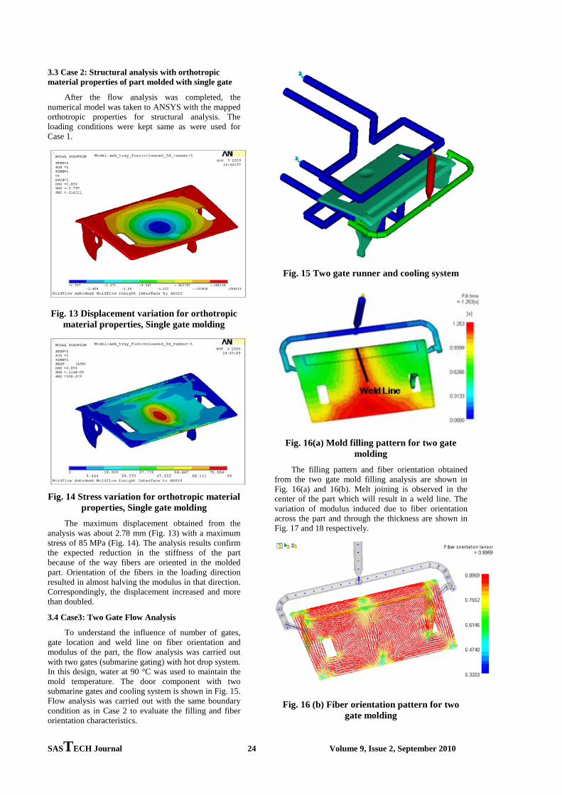
3.3 Case 2: Structural analysis with orthotropic material properties of part molded with single gate
After the flow analysis was completed, the numerical model was taken to ANSYS with the mapped orthotropic properties for structural analysis. The loading conditions were kept same as were used for Case 1.
Fig. 13 Displacement variation for orthotropic material properties, Single gate molding
Fig. 14 Stress variation for orthotropic material properties, Single gate molding
The maximum displacement obtained from the analysis was about 2.78 mm (Fig. 13) with a maximum stress of 85 MPa (Fig. 14). The analysis results confirm the expected reduction in the stiffness of the part because of the way fibers are oriented in the molded part. Orientation of the fibers in the loading direction resulted in almost halving the modulus in that direction. Correspondingly, the displacement increased and more than doubled.
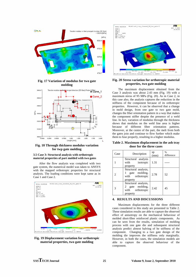
3.4 Case3: Two Gate Flow Analysis
To understand the influence of number of gates, gate location and weld line on fiber orientation and modulus of the part, the flow analysis was carried out with two gates (submarine gating) with hot drop system. In this design, water at 90 °C was used to maintain the mold temperature. The door component with two submarine gates and cooling system is shown in Fig. 15. Flow analysis was carried out with the same boundary condition as in Case 2 to evaluate the filling and fiber orientation characteristics.
Fig. 15 Two gate runner and cooling system
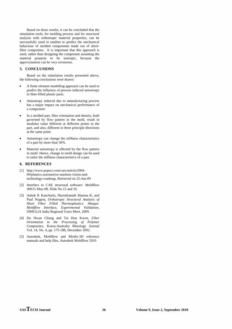
Fig. 16(a) Mold filling pattern for two gate molding
The filling pattern and fiber orientation obtained from the two gate mold filling analysis are shown in Fig. 16(a) and 16(b). Melt joining is observed in the center of the part which will result in a weld line. The variation of modulus induced due to fiber orientation across the part and through the thickness are shown in Fig. 17 and 18 respectively.
Fig. 16 (b) Fiber orientation pattern for two gate molding
SASTECH Journal 25 Volume 9, Issue 2, September 2010
Fig. 17 Variation of modulus for two gate molding
Fig. 18 Through thickness modulus variation for twp gate molding
3.5 Case 3: Structural analysis with orthotropic material properties of part molded with two gates
After the flow analysis was completed with two gate system, the numerical model was taken to ANSYS with the mapped orthotropic properties for structural analysis. The loading conditions were kept same as in Case 1 and Case 2.
Fig. 19 Displacement variation for orthotropic material properties, two gate molding
Fig. 20 Stress variation for orthotropic material properties, two gate molding
The maximum displacement obtained from the Case 3 analysis was about 2.43 mm (Fig. 19) with a maximum stress of 95 MPa (Fig. 20). As in Case 2, in this case also, the analysis captures the reduction in the stiffness of the component because of its orthotropic properties. However, it can be observed that a change in mold design, from one gate to two gate mold, changes the fiber orientation pattern in a way that makes the component stiffer despite the presence of a weld line. In fact, variation of modulus through the thickness shows that modulus on the weld line area is higher because of different fiber orientation patterns. Moreover, at the centre of the part, the melt from both the gates join and continue to flow further which make them to fuse properly, resulting in a higher modulus.
Table 2. Maximum displacement in the ash tray door for the three cases
Case Description sp (mm)
% difference
1 Structural analysis with isotropic property
1.31 -----
2
Structural analysis, 1 gate molding, with orthotropic property
2.78 52
3
Structural analysis, 2 gate molding, with orthotropic property
2.42 45
4. RESULTS AND DISCUSSIONS Maximum displacements for the three different
cases considered in this study are presented in Table 2. These simulation results are able to capture the observed effect of anisotropy on the mechanical behaviour of molded short-fiber reinforced plastic components. As can be seen from the results, simulation of molding process with one gate die and subsequent structural analysis predict almost halving of he stiffness of the component. Changing to a two gate design of the molding die improves the stiffness only marginally. However, in both the cases, the simulation models are able to capture the observed behaviour of the component.
SASTECH Journal 26 Volume 9, Issue 2, September 2010
Based on these results, it can be concluded that the simulation tools, for molding process and for structural analysis with orthotropic material properties, can be successfully used in tandem to predict the mechanical behaviour of molded components made out of short-fiber composites. It is important that this approach is used, rather than designing the component assuming the material property to be isotropic, because the approximation can be very erroneous.
5. CONCLUSIONS Based on the simulation results presented above,
the following conclusions were drawn:
• A finite element modelling approach can be used to predict the influence of process induced anisotropy in fiber-filled plastic parts.
• Anisotropy induced due to manufacturing process has a major impact on mechanical performance of a component.
• In a molded part, fiber orientation and density, both governed by flow pattern in the mold, result in modulus value different at different points in the part, and also, different in three principle directions at the same point.
• Anisotropy can change the stiffness characteristics of a part by more than 50%.
• Material anisotropy is affected by the flow pattern in mold. Hence, change in mold design can be used to tailor the stiffness characteristics of a part.
6. REFERENCES [1] http://www.popsci.com/cars/article/2004-
09/plastics-automotive-markets-vision-and-technology-roadmap, Retrieved on 25-Jun-09
[2] Interface to CAE structural software- Moldflow iMUG May-08, Slide No.15 and 16.
[3] Ashok K Kancharla, Harindranath Sharma K, and Paul Nugent, Orthotropic Structural Analysis of Short Fiber Filled Thermoplastics: Abaqus- Moldflow Interface, Experimental Validation, SIMULIA India Regional Users Meet, 2009.
[4] Du Hwan Chung and Tai Hun Kwon, Fiber Orientation in the Processing of Polymer Composites, Korea-Australia Rheology Journal Vol. 14, No. 4, pp. 175-188, December 2002.
[5] Autodesk, Moldflow and Moldx-3D reference manuals and help files, Autodesk Moldflow 2010