Embed Size (px)
Citation preview
Structural Requirements Language DefinitionDefining the ReDSeeDS Languages
Deliverable D2.2, version 1.00, 30.01.2007
IST-2006-033596ReDSeeDSRequirements DrivenSoftware Development Systemwww.redseeds.eu
Infovide-Matrix S.A., Poland
Warsaw University of Technology, Poland
Hamburger Informatik Technologie Center e.V., Germany
University of Koblenz-Landau, Germany
University of Latvia, Latvia
Vienna University of Technology, Austria
Fraunhofer IESE, Germany
Algoritmu sistemos, UAB, Lithuania
Cybersoft IT Ltd., Turkey
PRO DV Software AG, Germany
Heriot-Watt University, United Kingdom
Structural Requirements Language DefinitionDefining the ReDSeeDS Languages
Workpackage WP2Task T2.2Document number D2.2Document type DeliverableTitle Structural Requirements Language DefinitionSubtitle Defining the ReDSeeDS LanguagesAuthor(s) Hermann Kaindl, MichałSmiałek, Albert Ambroziewicz, Davor
Svetinovic, Jacek Bojarski, Wiktor Nowakowski, Tomasz Straszak,Mohamad Hani el Jamal, Lothar Hotz, Katharina Wolter, ThorstenKrebs, Hannes Schwarz, Daniel Bildhauer, Jürgen Falb, John PaulBrogan
Internal Reviewer(s) Daniel Bildhauer, Rober Draber, Hermann Kaindl, Sevan Kavaldjian,Thorsten Krebs, Roman Popp, Hannes Schwarz, Michal Smialek,Katharina Wolter, Radoslaw Ziembinski
Internal Acceptance Project BoardLocation https://svn.redseeds.eu/svn/redseeds/1_DeliverablesSpace/WP2_Re-
quirements_specification_language/D2.2.00/ReDSeeDS_D2.2_Struc-tural_Requirements_Language_Definition.pdf
Version 1.00Status FinalDistribution Public
The information in this document is provided as is and no guarantee or warranty is given that the information is fitfor any particular purpose. The user thereof uses the information at its sole risk and liability.
30.01.2007
Structural Requirements Language Definition – D2.2History of changes
ver. 1.0030.01.2007
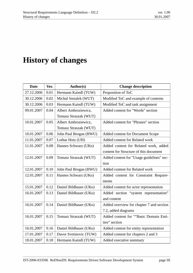
History of changes
Date Ver. Author(s) Change description
27.12.2006 0.01 Hermann Kaindl (TUW) Proposition of ToC
30.12.2006 0.02 Michal Smialek (WUT) Modified ToC and example of contents
30.12.2006 0.03 Hermann Kaindl (TUW) Modified ToC and task assignment
09.01.2007 0.04 Albert Ambroziewicz,
Tomasz Straszak (WUT)
Added content for "Words" section
10.01.2007 0.05 Albert Ambroziewicz,
Tomasz Straszak (WUT)
Added content for "Phrases" section
10.01.2007 0.06 John Paul Brogan (HWU) Added content for Document Scope
11.01.2007 0.07 Lothar Hotz (UH) Added content for Related work
11.01.2007 0.08 Hannes Schwarz (UKo) Added content for Related work, added
content for Structure of this document
12.01.2007 0.09 Tomasz Straszak (WUT) Added content for "Usage guidelines" sec-
tion
12.01.2007 0.10 John Paul Brogan (HWU) Added content for Related work
12.01.2007 0.11 Hannes Schwarz (UKo) Added content for Constraint Require-
ments
15.01.2007 0.12 Daniel Bildhauer (UKo) Added content for actor representation
16.01.2007 0.13 Daniel Bildhauer (UKo) Added section “system representation”
and content
16.01.2007 0.14 Daniel Bildhauer (UKo) Added overview for chapter 7 and section
7.2, added diagrams
16.01.2007 0.15 Tomasz Straszak (WUT) Added content for "“Basic Domain Enti-
ties” section
16.01.2007 0.16 Daniel Bildhauer (UKo) Added content for entity representation
17.01.2007 0.17 Davor Svetinovic (TUW) Added content for chapters 2 and 3
18.01.2007 0.18 Hermann Kaindl (TUW) Added executive summary
IST-2006-033596 ReDSeeDS: Requirements Driven Software Development System page III
Structural Requirements Language Definition – D2.2History of changes
ver. 1.0030.01.2007
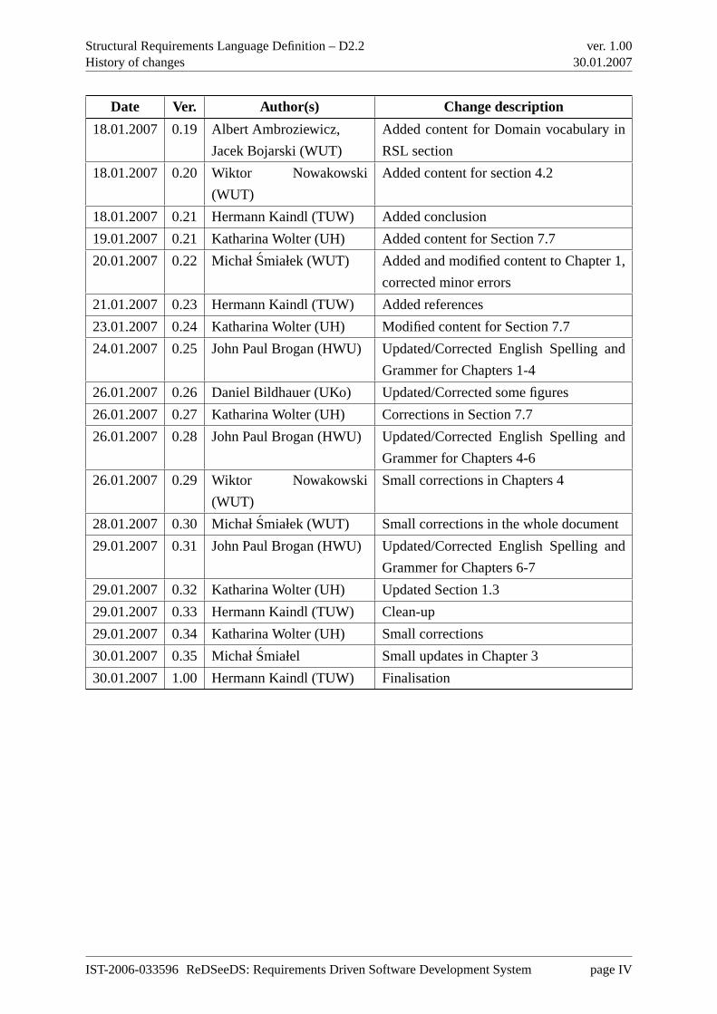
Date Ver. Author(s) Change description
18.01.2007 0.19 Albert Ambroziewicz,
Jacek Bojarski (WUT)
Added content for Domain vocabulary in
RSL section
18.01.2007 0.20 Wiktor Nowakowski
(WUT)
Added content for section 4.2
18.01.2007 0.21 Hermann Kaindl (TUW) Added conclusion
19.01.2007 0.21 Katharina Wolter (UH) Added content for Section 7.7
20.01.2007 0.22 Michał Smiałek (WUT) Added and modified content to Chapter 1,
corrected minor errors
21.01.2007 0.23 Hermann Kaindl (TUW) Added references
23.01.2007 0.24 Katharina Wolter (UH) Modified content for Section 7.7
24.01.2007 0.25 John Paul Brogan (HWU) Updated/Corrected English Spelling and
Grammer for Chapters 1-4
26.01.2007 0.26 Daniel Bildhauer (UKo) Updated/Corrected some figures
26.01.2007 0.27 Katharina Wolter (UH) Corrections in Section 7.7
26.01.2007 0.28 John Paul Brogan (HWU) Updated/Corrected English Spelling and
Grammer for Chapters 4-6
26.01.2007 0.29 Wiktor Nowakowski
(WUT)
Small corrections in Chapters 4
28.01.2007 0.30 Michał Smiałek (WUT) Small corrections in the whole document
29.01.2007 0.31 John Paul Brogan (HWU) Updated/Corrected English Spelling and
Grammer for Chapters 6-7
29.01.2007 0.32 Katharina Wolter (UH) Updated Section 1.3
29.01.2007 0.33 Hermann Kaindl (TUW) Clean-up
29.01.2007 0.34 Katharina Wolter (UH) Small corrections
30.01.2007 0.35 Michał Smiałel Small updates in Chapter 3
30.01.2007 1.00 Hermann Kaindl (TUW) Finalisation
IST-2006-033596 ReDSeeDS: Requirements Driven Software Development System page IV
Structural Requirements Language Definition – D2.2Summary
ver. 1.0030.01.2007
Summary
Existing approaches to object-oriented software development mostly focus onsoftware objects,
i.e., somethingwithin the software. Referring to such objects in a Requirements Specification
would blur the distinction between Requirements Specification and SoftwareDesign, however.
The structural part of our requirements specification language deals with models and descrip-
tions of objects existing in the domain (environment) of the software system to be built —
domain objects. These objects are part of a Domain Model (to-be) and/or described in a defined
vocabulary. This facilitates a better understanding of the requirements.
This deliverable contains the structural part of the requirements specification language, i.e.,
all the parts of the meta-model and other descriptions dealing with abstractions of important
objects existing in the environment of the software system to be built, as well as their attributes
and relations, including their relationships to the software system. Note, that this is a structural
requirements language definition, but it isnot about “structural requirements”. This deliverable
first gives a conceptual overview of this structural requirements specification language. In the
second part, it provides a comprehensive language reference including concrete syntax.
IST-2006-033596 ReDSeeDS: Requirements Driven Software Development System page V
Structural Requirements Language Definition – D2.2Table of contents
ver. 1.0030.01.2007
Table of contents
History of changes III
Summary V
Table of contents VI
List of figures VII
1 Scope, conventions and guidelines 1
1.1 Document scope . . . . . . . . . . . . . . . . . . . . . . . . . . . . . . . . . . 1
1.2 Approach to language definition and notation conventions . . . . . . . . . . . . 2
1.2.1 Defining languages using meta-modelling . . . . . . . . . . . . . . . . 2
1.2.2 Structure of the language reference . . . . . . . . . . . . . . . . . . . . 2
1.3 Related work and relation to other documents . . . . . . . . . . . . . . . . . . 2
1.4 Structure of this document . . . . . . . . . . . . . . . . . . . . . . . . . . . . 4
1.5 Usage guidelines . . . . . . . . . . . . . . . . . . . . . . . . . . . . . . . . . 4
I Conceptual Overview of the Structural Requirements Language 5
2 Introduction 6
2.1 Typical OOAD method . . . . . . . . . . . . . . . . . . . . . . . . . . . . . . 6
2.1.1 Requirements modelling . . . . . . . . . . . . . . . . . . . . . . . . . 7
2.1.2 OOA . . . . . . . . . . . . . . . . . . . . . . . . . . . . . . . . . . . . 7
2.1.3 OOD . . . . . . . . . . . . . . . . . . . . . . . . . . . . . . . . . . . 9
2.2 Our Language . . . . . . . . . . . . . . . . . . . . . . . . . . . . . . . . . . . 10
3 Domain entities 11
3.1 Business entities . . . . . . . . . . . . . . . . . . . . . . . . . . . . . . . . . . 11
3.2 System entities . . . . . . . . . . . . . . . . . . . . . . . . . . . . . . . . . . 12
4 Domain vocabulary representation 14
4.1 Overview . . . . . . . . . . . . . . . . . . . . . . . . . . . . . . . . . . . . . 14
4.2 Domain vocabulary concept . . . . . . . . . . . . . . . . . . . . . . . . . . . . 14
IST-2006-033596 ReDSeeDS: Requirements Driven Software Development System page VI
Structural Requirements Language Definition – D2.2Table of contents
ver. 1.0030.01.2007
4.3 Domain vocabulary in the RSL . . . . . . . . . . . . . . . . . . . . . . . . . . 16
5 Discussion 19
II Language Reference 20
6 Domain entities 21
6.1 Overview . . . . . . . . . . . . . . . . . . . . . . . . . . . . . . . . . . . . . 21
6.2 Basic domain elements . . . . . . . . . . . . . . . . . . . . . . . . . . . . . . 23
6.2.1 Overview . . . . . . . . . . . . . . . . . . . . . . . . . . . . . . . . . 23
6.2.2 Abstract syntax and semantics . . . . . . . . . . . . . . . . . . . . . . 24
6.2.3 Concrete syntax and examples . . . . . . . . . . . . . . . . . . . . . . 26
6.3 Actors . . . . . . . . . . . . . . . . . . . . . . . . . . . . . . . . . . . . . . . 28
6.3.1 Overview . . . . . . . . . . . . . . . . . . . . . . . . . . . . . . . . . 28
6.3.2 Abstract syntax and semantics . . . . . . . . . . . . . . . . . . . . . . 29
6.3.3 Concrete syntax . . . . . . . . . . . . . . . . . . . . . . . . . . . . . . 30
6.4 System representations . . . . . . . . . . . . . . . . . . . . . . . . . . . . . . 31
6.4.1 Overview . . . . . . . . . . . . . . . . . . . . . . . . . . . . . . . . . 31
6.4.2 Abstract syntax and semantics . . . . . . . . . . . . . . . . . . . . . . 31
6.4.3 Concrete syntax . . . . . . . . . . . . . . . . . . . . . . . . . . . . . . 33
6.5 Element representations . . . . . . . . . . . . . . . . . . . . . . . . . . . . . . 34
6.5.1 Overview . . . . . . . . . . . . . . . . . . . . . . . . . . . . . . . . . 34
6.5.2 Abstract syntax and semantics . . . . . . . . . . . . . . . . . . . . . . 34
6.5.3 Concrete syntax . . . . . . . . . . . . . . . . . . . . . . . . . . . . . . 35
6.6 Phrases . . . . . . . . . . . . . . . . . . . . . . . . . . . . . . . . . . . . . . 36
6.6.1 Overview . . . . . . . . . . . . . . . . . . . . . . . . . . . . . . . . . 36
6.6.2 Abstract syntax and semantics . . . . . . . . . . . . . . . . . . . . . . 36
6.6.3 Concrete syntax and examples . . . . . . . . . . . . . . . . . . . . . . 39
6.7 Terms . . . . . . . . . . . . . . . . . . . . . . . . . . . . . . . . . . . . . . . 40
6.7.1 Overview . . . . . . . . . . . . . . . . . . . . . . . . . . . . . . . . . 40
6.7.2 Abstract syntax and semantics . . . . . . . . . . . . . . . . . . . . . . 40
6.7.3 Concrete syntax and examples . . . . . . . . . . . . . . . . . . . . . . 47
7 Conclusion 50
Bibliography 51
IST-2006-033596 ReDSeeDS: Requirements Driven Software Development System page VII
Structural Requirements Language Definition – D2.2List of figures
ver. 1.0030.01.2007
List of figures
4.1 Scenario with separated domain vocabulary . . . . . . . . . . . . . . . . . . . 16
6.1 Overview of packages inside theDomainEntities part of RSL . . . . . . . . . . 22
6.2 Basic domain elements . . . . . . . . . . . . . . . . . . . . . . . . . . . . . . 24
6.3 DomainVocabulary example, normal and tree view . . . . . . . . . . . . . . . 26
6.4 DomainElement tree view example . . . . . . . . . . . . . . . . . . . . . . . . 27
6.5 DomainElement’s diagram example . . . . . . . . . . . . . . . . . . . . . . . 27
6.6 DomainElement’s diagram example . . . . . . . . . . . . . . . . . . . . . . . 28
6.7 DomainElementRepresentation’s concrete syntax example . . . . . . . . . . . 28
6.8 DomainStatement example . . . . . . . . . . . . . . . . . . . . . . . . . . . . 28
6.9 Actor metamodel part . . . . . . . . . . . . . . . . . . . . . . . . . . . . . . . 29
6.10 The concrete syntax of an actor. . . . . . . . . . . . . . . . . . . . . . . . . . . 30
6.11 System representations . . . . . . . . . . . . . . . . . . . . . . . . . . . . . . 32
6.12 The concrete syntax of an system component. . . . . . . . . . . . . . . . . . . 33
6.13 Entity representations . . . . . . . . . . . . . . . . . . . . . . . . . . . . . . . 34
6.14 Phrases . . . . . . . . . . . . . . . . . . . . . . . . . . . . . . . . . . . . . . 37
6.15 Phrase concrete syntax examples . . . . . . . . . . . . . . . . . . . . . . . . . 39
6.16 SimpleVerbPhrase concrete syntax examples . . . . . . . . . . . . . . . . . . . 39
6.17 ComplexVerbPhrase concrete syntax examples . . . . . . . . . . . . . . . . . . 39
6.18 Thesaurus, Term and its specialisations. . . . . . . . . . . . . . . . . . . . . . 41
6.19 Specialisation Relations of terms from the same type. . . . . . . . . . . . . . . 42
6.20 Part of a Thesaurus in abstract syntax with organisation-specific extension (only
Nouns are presented in this figure.) . . . . . . . . . . . . . . . . . . . . . . . . 43
6.21 Part of a Thesaurus in abstract syntax with organisation-specific extension (only
Verbs are presented in this figure.) . . . . . . . . . . . . . . . . . . . . . . . . 44
6.22 Package view: thesaurus’s concrete syntax. . . . . . . . . . . . . . . . . . . . . 48
6.23 Thesaurus tree view example . . . . . . . . . . . . . . . . . . . . . . . . . . . 48
IST-2006-033596 ReDSeeDS: Requirements Driven Software Development System page VIII
Structural Requirements Language Definition – D2.2Scope, conventions and guidelines
ver. 1.0030.01.2007
Chapter 1
Scope, conventions and guidelines
1.1 Document scope
This document provides a conceptual overview, and defines syntax and semantics for the ReD-
SeeDS Structural Requirements Language (SRL). This definition is required to aid the construc-
tion of accurate requirements specifications in the form of descriptive or model-based represen-
tations.
The conceptual overview of the SRL explains the approach taken to allow for describing struc-
tural requirements meant as vocabularies and thesauruses or ontologies containing domain ele-
ments, including terms used in the domain and their descriptions. This document then presents
the SRL Reference which covers definitions for Domain elements. This reference explains the
syntax of the language in its abstract form (using a meta-model) and in its concrete form (using
concrete examples of language usage). The semantics of all the language constructs is also
defined.
The definitions for Domain elements describe language constructs that allow for depicting el-
ements of the domain vocabulary. This explains how to structure domain elements into full
vocabularies. It also defines possible relationships between domain elements, including the
system under development and actors. The reference for Domain elements defines top-level,
general representations for all the constructs of the language, including its behavioural and UI
part (see deliverables D2.1, D2.3). It also defines how to express phrases and terms that can be
used for representing Domain elements. Within its definition, the SRL uses hyperlinks as basic
facilitators of coherence. This allows for building a requirements specification where behav-
IST-2006-033596 ReDSeeDS: Requirements Driven Software Development System page 1
Structural Requirements Language Definition – D2.2Scope, conventions and guidelines
ver. 1.0030.01.2007
ioural and quality requirements are based on the domain vocabulary, thus greatly enhancing the
possibility to reuse it in the future.
1.2 Approach to language definition and notation conventions
1.2.1 Defining languages using meta-modelling
The Structural Requirements Language (SRL) is defined using a meta-model. A meta-model
can be treated as a definition of a language in which models can be expressed properly. A meta-
model sets well-formedness rules for models. A model has to comply with the meta-model of
the language it uses. In defining the whole Requirements Specification Language (RSL) we use
MOF [Obj03] as a meta-modelling language. More details on the meta-modelling approach and
notation conventions are given in D2.1, section 1.2.
1.2.2 Structure of the language reference
Part II of this document contains the SRL definition. It has been divided into sections according
to logical structure of packages of the BRL.
SRL is contained in a single main package “Domain elements” which starts with an overview
of division into subpackages. Every subpackage is presented in an overview explaining general
ideas behind a package, a meta-model diagram for this package and two sections which describe
the abstract syntax with the semantics of language constructs and their concrete syntax.
1.3 Related work and relation to other documents
External research work conducted in compliance with formulating a good understanding of
the Structural Requirements Language included researching and reasoning about such areas
as software case representations, query procedure pragmatics, Domain representation, Do-
main mapping with or without hyperlinking, Domain access methods via taxonomies and sim-
ilarity measures concerning domain constructs (vocabulary items) and requirement dependen-
cies/interdependencies leading to possible upgrades of the domain or industry specific dictio-
nary of terms.
IST-2006-033596 ReDSeeDS: Requirements Driven Software Development System page 2
Structural Requirements Language Definition – D2.2Scope, conventions and guidelines
ver. 1.0030.01.2007
In Chapters 3, 4 and 6 means for modelling domain entities are introduced, such as domain
entity types, vocabulary, phrases, and terms. Terms are organized in a thesaurus. Domain enti-
ties are used for representing requirements ofeachnew software development project forming
a requirement model of the developed software case. For performing case retrieval on the basis
of similarity measures, this requirement model is mapped and included in a so-calledsoftware
knowledge model. This software knowledge model contains the knowledge known forall soft-
ware cases of an organisation i.e. the software vendor that implements the different software
cases.
For reuse purposes, we strive in this project for finding software cases based on similarity mea-
sures. In principle, this can be done by text-based approaches, where our thesaurus as defined
in the language will be very useful. For including more semantics into similarity measures, an
ontologyof the given application domain should be available. While our requirements language
does not yet include any means for knowledge representation and reasoning, the user may still
use it to represent a domain model using object-oriented means (in the form of a domain ele-
ment diagram, as derived from a UML class diagram). Such models can be used as a simple
form of ontology. These issues will be worked out in Workpackages 3 and 4 of ReDSeeDS and
discussed in the related deliverables.
One form of representing requirements in ReDSeeDS is to write them down in constrained
language. This constrained language uses the so-calledSVO(O)-Grammar, recently researched
at WUT [SBNS05b, SBNS05a]. Other significant work concerning some kind of restriction
to natural language was and is still done in theAttemptoresearch project conducted by the
Department of Informatics and the Institute of Computational Linguistics at the University of
Zurich [FHK+05].
The Attempto Controlled English (ACE)language developed in the course of theAttempto
project is currently available in its fifth version. Although ACE closely resembles natural Eng-
lish, the syntax of a text written in ACE is based on a defined abstract grammar which avoids
ambiguity in language constructs [Hoe04]1. Furthermore, ACE can be automatically translated
into first-order logic and consequently be read by humans as well as by machines.
1The cited article contains abstract grammar for ACE 4.0. The grammar for version 5.0 has not been publishedyet.
IST-2006-033596 ReDSeeDS: Requirements Driven Software Development System page 3
Structural Requirements Language Definition – D2.2Scope, conventions and guidelines
ver. 1.0030.01.2007
1.4 Structure of this document
Part I of this document, covering chapters 2 to 4, gives a conceptual overview of the Structural
Requirements Language. While chapter 2 serves as an introduction, the following chapters 3
and 4 describe different types of entities existing in a domain and the conceptual model of the
domain’s vocabulary, respectively.
Part II, after discussing the benefits and consequences of using a domain vocabulary in its first
chapter 5, defines six major packages of the language meta-model in its second chapter 6. The
first four of these packages are related to the basic domain entities, the actors in the system’s
environment and the representations of the system and the entities. The fourth package contains
phrases and other, more fine-grained elements which compose phrases. Phrases constitute the
names of the entities as well as the parts of a sentence in constrained language. The last package
comprises the individual terms which can occur in a phrase. Each section concerning one of
the packages has an overview, defines abstract syntax and semantics, and then gives a short
explanation of the concrete syntax using the Fitness Club case study as a running example.
The final Chapter ,7, sums up the document and draws conclusions from the previous parts.
1.5 Usage guidelines
ReDSeeDS Structural Requirements Language (SRL) definition should be used as a book that
guides the reader through the structure, syntax and semantics of the SRL, as part of the complete
ReDSeeDS Requirements Specification Language. It should be used mainly by creators of
appropriate CASE tools that would allow handling of the language by end users (analysts, etc.)
to express descriptions of static elements (domain elements) of the system under development.
It can be used by advanced end users of the language as a reference to the language’s syntax and
semantics. Examples of SRL elements’ concrete syntax have illustrative character and should
be treated only as support in understanding of each element’s occurrence.
Users of the SRL Specification are expected to know the basics of metamodelling and MOF
(Meta Object Facility) specification [Obj06]. Knowledge of UML ([Obj05b] and [Obj05a])
could be helpful as some elements of SRL are extensions, constraints or redefinitions of UML
elements.
IST-2006-033596 ReDSeeDS: Requirements Driven Software Development System page 4
Structural Requirements Language Definition – D2.2 ver. 1.0030.01.2007
Part I
Conceptual Overview of the Structural
Requirements Language
IST-2006-033596 ReDSeeDS: Requirements Driven Software Development System page 5
Structural Requirements Language Definition – D2.2Introduction
ver. 1.0030.01.2007
Chapter 2
Introduction
The Structural Requirements Language Definition is primarily concerned with the specification
of entities or concepts in an application domain. Referring explicitly to entities of an application
domain from requirements was proposed in [Kai97].
Traditionally, we use object-oriented analysis and design methods to discover these entities in
a domain and then use them for design purposes. However, several misunderstandings existed
about which entities are to be represented in the course of object-oriented analysis. For a dis-
cussion and clarification see [Kai99]. A clear separation between analysis and design artefacts
in a meta-model can be found in [EK02].
In this chapter we describe a common approach to OOAD, i.e., how the domain entities are
discovered and used, and in the next chapter we discuss what is typically captured using these
types of methods and how our language documents it.
2.1 Typical OOAD method
This section describes the parts of a typical object-oriented analysis and design (OOAD) method.
Full details about OOAD methods can be found in many OOAD books and articles (e.g. [Lar01,
Gom01, Dou99, Kai99]).
IST-2006-033596 ReDSeeDS: Requirements Driven Software Development System page 6
Structural Requirements Language Definition – D2.2Introduction
ver. 1.0030.01.2007
2.1.1 Requirements modelling
Input: Business tasks, use cases, and other business engineering artifacts.
Goal: Break down business-level artifacts in order to capture and define the scope and respon-
sibilities of a system to be built that meets the requirements embodied in the input.
Activities: The main requirements modelling activities are:
• Identify mainbusiness goals, processes, resources, andfeatures.
• Write use case descriptions with a clear identification of theactorsand thedataex-
changed between the system and the environment, and thecontextexpressed through
pre-conditions, post-conditions and invariants.
• Draw a use case diagram with all the use cases in order to depict the relationships
among use cases.
2.1.2 OOA
Input: All Requirements Modelling artifacts.
Goal: Decompose requirements artifacts and build a domain model.
Activities: The main OOA activities are:
• Relate use cases to each other with respect to their main concerns. This produces
the first level of the domain’s decomposition into related functionality domains, that
is, the domain subsystems. Show the decomposition of the use case diagrams using
the UML package notation. Repeat this step for any identified domain subsystem.
• For each domain subsystem, from its task and use case descriptions, extract its
classes, attributes, and the relationships among them. Show the decomposition us-
ing UML-like class notation in what is known as a domain model (DM). This step
is present in most OOA methods. Our opinion is that use case conceptual analysis
is not an effective way for developing the DM. Analysts should have good prior do-
main knowledge, which should be the main source for domain concepts. Of course,
in the absence of knowledge of the domain, use case conceptual analysis at least
represents a good starting point.
• Extract common concepts from different domain subsystems and allocate them to
common domain subsystems.
IST-2006-033596 ReDSeeDS: Requirements Driven Software Development System page 7
Structural Requirements Language Definition – D2.2Introduction
ver. 1.0030.01.2007
• Emphasise relationships among data concepts in the DM. Data concepts represent
external data with a high probability of having to be used and preserved within
the system. These data concepts and their relationships constitute the traditional
relational part of the DM.
• With use cases, develop the domain-level interaction diagram. The main goal of this
step is to define the domain’s external interface.
• With use cases, DMs, and the domain-level interaction diagram, for each domain
subsystem, develop the domain subsystem interaction diagrams. The main goal of
this step is to define the domain subsystems’ interfaces. Use higher-level domain
subsystem interaction diagrams to develop the lower-level domain subsystem inter-
action diagrams. This activity is recursive.
• With use cases, DMs, and the domain subsystem interaction diagrams, develop the
low-level object interaction diagrams. The main goal of this step is to capture:
– how objects collaborate to accomplish the functionality described in use cases
— note, these objects are the objects from the domain and not the software
objects,
– definitions of object interfaces,
– object associations and interactions, and
– the sequence of the objects’ interactions.
• With all interaction diagrams, build a unified collaboration diagram (UCD) without
message numbering, multiple objects of the same type, or object names. Indicate:
– Controller andcoordinator objects— the main sources for the definitions of
active objectsin the design phase.
– Entity and service objects— the main sources for the definitions ofpassive
objectsin the design phase.
– External objects— the main sources for the definitions ofinterfacesin the
design phase. These objects include devices and business resources.
• With the UCD, record each message as a method in the DM.
• For each controller and coordinator object in the UCD, develop a state diagram.
The messages from the UCD are the main sources of events; the mapping is not
necessarily one to one.
• Develop state diagrams for any additional objects that have non-trivial state transi-
tions. The messages from the UCD are the main sources of events; the mapping is
not necessarily one to one due to the possible presence of internal events.
Additional Notes: It is usually recommended that one should capture invariants, pre-conditions,
and post-conditions for each entity in the OOA artifacts. Each entity or artifact has to be
IST-2006-033596 ReDSeeDS: Requirements Driven Software Development System page 8
Structural Requirements Language Definition – D2.2Introduction
ver. 1.0030.01.2007
taken into account and to be related by its constraints, business goals, business rules,
non-functional requirements, to other artifacts captured during the requirements model-
ing phase.
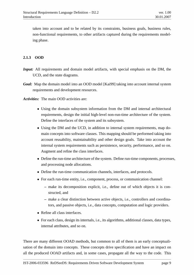
2.1.3 OOD
Input: All requirements and domain model artifacts, with special emphasis on the DM, the
UCD, and the state diagrams.
Goal: Map the domain model into an OOD model [Kai99] taking into account internal system
requirements and development resources.
Activities: The main OOD activities are:
• Using the domain subsystem information from the DM and internal architectural
requirements, design the initial high-level non-run-time architecture of the system.
Define the interfaces of the system and its subsystem.
• Using the DM and the UCD, in addition to internal system requirements, map do-
main concepts into software classes. This mapping should be performed taking into
account reusability, maintainability and other design goals. Take into account the
internal system requirements such as persistence, security, performance, and so on.
Augment and refine the class interfaces.
• Define the run-time architecture of the system. Define run-time components, processes,
and processing node allocations.
• Define the run-time communication channels, interfaces, and protocols.
• For each run-time entity, i.e., component, process, or communication channel:
– make its decomposition explicit, i.e., define out of which objects it is con-
structed, and
– make a clear distinction between active objects, i.e., controllers and coordina-
tors, and passive objects, i.e., data concepts, computation and logic providers.
• Refine all class interfaces.
• For each class, design its internals, i.e., its algorithms, additional classes, data types,
internal attributes, and so on.
There are many different OOAD methods, but common to all of them is an early conceptuali-
sation of the domain into concepts. These concepts drive specification and have an impact on
all the produced OOAD artifacts and, in some cases, propagate all the way to the code. This
IST-2006-033596 ReDSeeDS: Requirements Driven Software Development System page 9
Structural Requirements Language Definition – D2.2Introduction
ver. 1.0030.01.2007
propagation of the concepts and the concepts’ influence on the other produced artifacts might
have both positive and negative effects.
2.2 Our Language
A typical approach to OOAD is described above. Our language can be useful for the early
stages of such an approach. Nevertheless, our language introduces a number of changes and
enhancements. Namely, we do not use UML class diagrams with attributes and methods. We
use “domain entity diagrams”, where domain elements have Phrases. Our language describes
these domain entities. Our language also allows for linking the vocabulary precisely with the
behavioural and quality requirements. However, we are also not limited to use cases only.
IST-2006-033596 ReDSeeDS: Requirements Driven Software Development System page 10
Structural Requirements Language Definition – D2.2Domain entities
ver. 1.0030.01.2007
Chapter 3
Domain entities
The main purpose of a domain model (DM) is to capture the entities that exist in a system’s
domain. The domain can be seen as consisting of:
• business entities, and
• computer entities, including hardware and software.
In the sections below we discuss these two main groups.
3.1 Business entities
A software system is part of a larger business system, and serves as a resource to accomplish
business goals. To build a useful DM, we need to study and discover different business entities
of the domain. The possible sources of business entities are presented below:
1. Business Resources— All entities, both physical and abstract, that exist inside the en-
vironment of the business are business resources. They include people, information,
different systems, and business supplies and products. They participate in the business
processes. A subset of these resources is a source of modelling entities for the system to
be built. The value of tracking and preserving knowledge about these entities is that these
entities are used to perform analysis of the system’s architecture, to track changes to the
IST-2006-033596 ReDSeeDS: Requirements Driven Software Development System page 11
Structural Requirements Language Definition – D2.2Domain entities
ver. 1.0030.01.2007
domain and the system from the beginning, and to evaluate how well the system reflects
current business needs. For an elevator system, an example business resource is thecable
used to pull up the elevator cab.
2. Business Processes— A system to be built may participate later in several business
processes in order to help achieve several business goals. Use cases (UCs) describe sub-
processes of larger business processes that are automated by the software system. It is
important to understand a business process as it relates its UCs, which in turn relate soft-
ware requirements that the system has to satisfy. For an elevator system, an example
business process isa passenger’s riding of an elevator cab.
3. Business Rules— Business rules are a major source of constraints on a software system.
Many constraints directly influence the system’s architecture. Therefore, it is important
to understand these constraints and to keep track of them, for example, to be able to
remove architectural limitations imposed by constraints that do not hold any more. For
an elevator system, an example business rule isthe elevator will not change its direction
until it services all previously received calls that lie in the current travelling direction.
The main source of business domain objects are Business Resources, but they are very tightly
interlinked with Business Processes and Business Rules. In some cases, they cannot exist sep-
arately. Therefore, we need to seek for domain objects inside business process or business
rule descriptions. These are not intended to be described using our Structural Requirements
Language (SRL), but can be sources to elements expressed in the SRL.
3.2 System entities
It is often a case that we are building a new system for which domain consists of an already
existing computer-based system that includes both software and hardware. For such a system,
domain entities are not some “natural” objects but rather software and hardware components
and other building blocks. For such domains, the main aspects of a system that should be
modelled are:
• System,
• subsystems,
• modules,
IST-2006-033596 ReDSeeDS: Requirements Driven Software Development System page 12
Structural Requirements Language Definition – D2.2Domain entities
ver. 1.0030.01.2007
• connectors,
• processes, and
• hardware devices.
The System1 entity defines the outermost boundary of the system under consideration. The
Systemserves as a container for all other entities, and defines the system as a resource in the
business system.
A subsystemis a part of aSystemor asubsystem, being an abstraction of actual physical mod-
ules, connectors, and processes. It serves as a container and a building block.
A moduleis a basic architectural building block. For example, in the logical view, it represents
a entity that occurs in a domain, and in the implementation view, it represents a code unit.
Modulesare abstractions of basic building blocks of the domain, depending on the development
technology used.
A connectoris an abstraction of a communication mechanism or a channel that exists in a
system. Its size and complexity vary from a simple procedure call to a connection on the
Internet.
A processis an executable piece of software.Processesare basic building blocks of a run-time
architectural view.
A hardware deviceis an entity that occurs in the run-time architectural view, and it represents a
physical device that is a part of the system.
The above types of system entities have their place in the domain model created at the require-
ments level, using the SRL. The System entity is used throughout the descriptions of functional
requirements in general, and in use case descriptions (scenarios) specifically. Other system en-
tities can be used in requirements that specify technical constraints on the prospective system.
Refer to document D2.1 for more details.
1Note that this “system” is spelled out with initial uppercase letter to distinguish it from the generic “system”used elsewhere.
IST-2006-033596 ReDSeeDS: Requirements Driven Software Development System page 13
Structural Requirements Language Definition – D2.2Domain vocabulary representation
ver. 1.0030.01.2007
Chapter 4
Domain vocabulary representation
4.1 Overview
This Chapter introduces the concept of domain vocabulary. In Section 4.2 the need to separate
the vocabulary from a requirements representation is explained. This section also describes the
structure of domain vocabularies. Section 4.3 shows the idea of the vocabulary in the context
of the whole ReDSeeDS Requirements Specification Language (RSL).
4.2 Domain vocabulary concept
The main purpose of a requirements specification in software engineering is to reflect the real
needs of the clients. This specification should be the basis on which developers build a soft-
ware system of a good quality – i.e. a system that meets clients’ expectations to high extent.
Unfortunately, a commonly encountered problem with requirements specifications is that they
are imprecise and have many inconsistences. Specifications are often written using wordy style
or, on the contrary, they are too general. In both cases, the intentions of the writer are hard to
understand and interpret causing ambiguity. The majority of requirements specification writers
tend to mix descriptions of the system’s behaviour, quality or appearance with descriptions of
notions from the application (problem) domain. Definitions of notions are buried in many differ-
ent places inside scenarios, stories or simply free text. What is more harmful, the same notions
often have conflicting definitions and, on the other hand, a number of different synonyms are
used to describe identically (or close to identically) defined notions. Having the requirements
specification of such a poor quality, it is a very hard task to build a system that fully fulfills the
IST-2006-033596 ReDSeeDS: Requirements Driven Software Development System page 14
Structural Requirements Language Definition – D2.2Domain vocabulary representation
ver. 1.0030.01.2007
real clients’ needs. It is hard to reflect these requirements in the architecture and in the design
of the prospective system as well as to apply changes in the system when requirements change.
Finally, imprecise requirements make it close to impossible to apply the concept of software
reuse at the level of problem definition.
To overcome all problems mentioned above, we need a special language for creating precise
and consistent requirements specifications. With this language we should be able to describe all
functional and non-functional requirements on the prospective system with the simplest possible
sentences in well defined grammar. For example, to describe interactions between a customer
of a fitness club and the fitness club system in a scenario, sentences in SVO(O) grammar (see
deliverable D2.1) could be used:
• Customer wants to sign up for exercises.
• System shows time schedule.
• Customer chooses time from time schedule.
With these simple sentences we can precisely describe actions performed by an actor or by the
system. However, they are not appropriate for defining the notions used therein. For example,
we lack explanation of what ‘exercises’ or ‘time schedule’ is and how they relate to each other.
In order to avoid inconsistencies, as mentioned above, we should not insert definitions of no-
tions into the sentences. Thus, the requirements specification language should provide means
to describe the environment of the system. We need to have adomain vocabulary– a repos-
itory that keeps all necessary notions from the system’s domain along with their definitions
and relationships between them. For the above example, the domain vocabulary would contain
definitions for nouns:
Exercises –Form of physical activity performed in fitness club. Exercises may be [cyclic ex-
ercises] or [sporadic exercises].
Time schedule –A program of [exercises] offered to [customers] by the [fitness club] in a
given period of time: day, week or month.
Square brackets in notion definitions denote relationships with other notions. Every notion in
the domain vocabulary can have different forms (i.e. singular and plural) and synonyms. In
addition to nouns, the domain vocabulary can also contain verbs. However, verbs do not have
their own autonomous definitions – they are related to nouns as their meaning depends on the
IST-2006-033596 ReDSeeDS: Requirements Driven Software Development System page 15
Structural Requirements Language Definition – D2.2Domain vocabulary representation
ver. 1.0030.01.2007
1. Customer wants to sign up for exercises.2. System checks availability of exercises.3. System shows time schedule.4. Customer chooses time from time schedule.5. System shows sign-up summary dialog.6. Customer submits sign-up for exercises.7. System signs up customer for exercises.
customer
time schedule
exercises
sign-up
sign-up summary dialog
timeavailability
Domain vocabulary
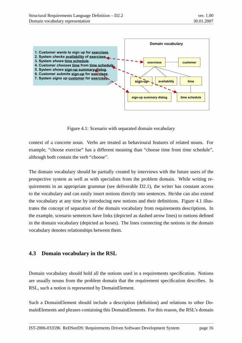
Figure 4.1: Scenario with separated domain vocabulary
context of a concrete noun. Verbs are treated as behavioural features of related nouns. For
example, “choose exercise” has a different meaning than “choose time from time schedule”,
although both contain the verb “choose”.
The domain vocabulary should be partially created by interviews with the future users of the
prospective system as well as with specialists from the problem domain. While writing re-
quirements in an appropriate grammar (see deliverable D2.1), the writer has constant access
to the vocabulary and can easily insert notions directly into sentences. He/she can also extend
the vocabulary at any time by introducing new notions and their definitions. Figure 4.1 illus-
trates the concept of separation of the domain vocabulary from requirements descriptions. In
the example, scenario sentences have links (depicted as dashed arrow lines) to notions defined
in the domain vocabulary (depicted as boxes). The lines connecting the notions in the domain
vocabulary denotes relationships between them.
4.3 Domain vocabulary in the RSL
Domain vocabulary should hold all the notions used in a requirements specification. Notions
are usually nouns from the problem domain that the requirement specification describes. In
RSL, such a notion is represented by DomainElement.
Such a DomainElement should include a description (definition) and relations to other Do-
mainElements and phrases containing this DomainElements. For this reason, the RSL’s domain
IST-2006-033596 ReDSeeDS: Requirements Driven Software Development System page 16
Structural Requirements Language Definition – D2.2Domain vocabulary representation
ver. 1.0030.01.2007
vocabulary is based on the phrase concept. Every DomainElement is described by its wiki-like
description (text with hyperlinks relating to other notions or phrases). Its name is a phrase,
composed from noun terms (and optionally some modifiers and/or quantifiers). DomainEle-
ment also contains a set of phrases referring to this notion. A phrase, in a similar way to a
notion, contains its definition in the wiki-like description form.
Every phrase is based on terms existing in a general thesaurus. A thesaurus stores terms with
their inflections, classified by their types of speech. These terms are the building blocks for
phrases. Terms in a thesaurus are related to their homonyms and synonyms. Such information
allows for measuring similarity between phrases composed of such terms. This mechanism
makes it possible to use not only identical, but also similar phrases when trying to reuse re-
quirements.
In RSL we need a set of grammars that would allow us to express precise, coherent and well-
formulated user requirements. If these grammars are based on a properly structured vocabulary,
they ensure separation of concerns (behaviour from the environment description) and guarantee
consistency of requirements expressed.
The proposal to use a domain vocabulary structure facilitates creation of other parts of the RSL
(behavioural, UI, quiality) through the use of phrases as atomic “lexemes”. Any phrase can be
perceived as a complex domain vocabulary element. Using phrases as lexemes we can easily
define grammars based on such complex elements. For example we can define an SVO(O)
sentence (see deliverable D2.1) using just two phrases: a subject phrase and a predicate phrase.
Subject can include any noun from a domain vocabulary grouped with its quantifier and modifier
(which together form a noun phrase, e.g.every registered customer, authorized user). Predicate
is a more complex phrase, containing a verb and possibly referring to some other notion (it is
a noun phrase). Such a VerbPhrase forms the VO (simple verb phrase) or VOO (complex verb
phrase pointing also to another notion) part of the sentence. Let’s now consider the following
example sentences that use the SVO(O) grammar:
• User submits form.
• System adds user to the user list.
• Registered customer cancels reservation.
The first sentence consists of theuser phrase (a noun with no quantifier or modifier) in the
role of a subject and thesubmits formsimple verb phrase in the role of a predicate (VO part
of the sentence). The second sentence consists of thesystemphrase in the role of a subject
IST-2006-033596 ReDSeeDS: Requirements Driven Software Development System page 17
Structural Requirements Language Definition – D2.2Domain vocabulary representation
ver. 1.0030.01.2007
and theadds user to the user listcomplex verb phrase (pointing to theuser listnotion) in the
role of predicate (VOO part of the sentence). In the third sentence we have an example of a
more complex noun phraseregistered customer(containing a modifier). For more details and
examples please refer to Chapter 6
IST-2006-033596 ReDSeeDS: Requirements Driven Software Development System page 18
Structural Requirements Language Definition – D2.2Discussion
ver. 1.0030.01.2007
Chapter 5
Discussion
Requirements can be compared to novels in literature. Good novels communicate stories treated
as sequences of events, and place these stories in a well described environment. Unfortunately,
writing “stories” that describe requirements for software systems seems to be equally as hard as
(or harder) than as writing good novels. However, unlike writing novels, lack of coherence and
ambiguities may cause disaster when developing a system based on such requirements.
Finding inconsistencies in a set of several tens or hundreds of requirements is quite a hard
task, especially, when these requirements are written by different people and at different times.
It seems that keeping the vocabulary separate from the rest of the requirements specification
can significantly facilitate keeping sparse requirements documents consistent by keeping the
vocabulary controlled. This is because most inconsistencies in requirements are caused by
contradictory definitions of terms. To eliminate the source of such inconsistencies we introduce
a single repository of notions (a vocabulary) that can be used in various requirements. This
means that for instance, the behavioural requirements could use definitions already found in the
repository and just concentrate on the actual sequence of events.
In addition to the above, having a clearly defined vocabulary makes it possible to introduce
certain query mechanisms that would allow for easy retrieval and reuse of requirements. For
such mechanisms it is very important to be able to compare requirements. This comparison
should be based on a thesaurus where terms with similar meaning are related. It has to be
stressed that the language to define vocabularies has to be used in conjunction with a tool.
This is necessary as using notions stored in a vocabulary within requirements and keeping it
constantly coherent would be very laborious and error-prone if done manually. Thus such a
tool would need allow for providing consistency between different requirements using the same
notions (notion has the same definition wherever it is used).
IST-2006-033596 ReDSeeDS: Requirements Driven Software Development System page 19
Structural Requirements Language Definition – D2.2 ver. 1.0030.01.2007
Part II
Language Reference
IST-2006-033596 ReDSeeDS: Requirements Driven Software Development System page 20
Structural Requirements Language Definition – D2.2Domain entities
ver. 1.0030.01.2007
Chapter 6
Domain entities
6.1 Overview
The DomainEntities part defines the domain description aspects of a requirements specification.
All terms that are domain related, for instance actors and components of the system under
development as well as special actions of actors or the system will be stored in the domain
vocabulary.
While this part of the language has a focus on structured language, it also allows basic object-
oriented representation of structured domain knowledge in the spirit of UML class diagrams.
So, even a simple form of ontology can be represented in this language. Further work on the
query mechanism in WP4 and the experiences from industrial applications during ReDSeeDS
will show whether extensions of the requirements language would be desirable for supporting
a knowledge representation and reasoning approach, which would support the representation of
ontologies even better.
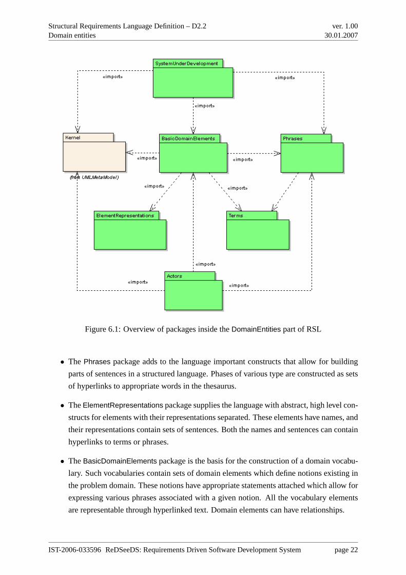
The specification in this part of the Requirements Specification Language contains six packages
as shown in Figure 6.1.
• The Terms package contains constructs that allow for building a thesaurus of words
(terms) that can be used in various requirements specifications. Out of these terms, more
complex constructs, like phrases can be built. This is done through the use of hyperlinks
to appropriate terms in the thesaurus.
IST-2006-033596 ReDSeeDS: Requirements Driven Software Development System page 21
Structural Requirements Language Definition – D2.2Domain entities
ver. 1.0030.01.2007
Figure 6.1: Overview of packages inside theDomainEntities part of RSL
• The Phrases package adds to the language important constructs that allow for building
parts of sentences in a structured language. Phases of various type are constructed as sets
of hyperlinks to appropriate words in the thesaurus.
• TheElementRepresentations package supplies the language with abstract, high level con-
structs for elements with their representations separated. These elements have names, and
their representations contain sets of sentences. Both the names and sentences can contain
hyperlinks to terms or phrases.
• TheBasicDomainElements package is the basis for the construction of a domain vocabu-
lary. Such vocabularies contain sets of domain elements which define notions existing in
the problem domain. These notions have appropriate statements attached which allow for
expressing various phrases associated with a given notion. All the vocabulary elements
are representable through hyperlinked text. Domain elements can have relationships.
IST-2006-033596 ReDSeeDS: Requirements Driven Software Development System page 22
Structural Requirements Language Definition – D2.2Domain entities
ver. 1.0030.01.2007
• The Actors package allows for defining actors as part of the domain vocabulary. There
can be shown relationships between actors. Actors are representable, and can have de-
scriptions in hyperlinked text.
• The SytemUnderDevelopment package adds to the vocabulary the possibility to express
the system and its general components. This does not allow for designing the system but
allows for showing those elements of the system that might be used inside requirements
specifications.
Generally, the vocabularies defined through our language consist ofRepresentableElements
which have names andHyperlinkedSentences as descriptions. Since theseHyperlinkedSen-
tences may containHyperlinks,RerpesentableElements resp. their descriptions that are related
to each other are logically connected.
RepresentableElements can be actors, system components, special actions or entities that are
domain-related, but not part of the system under development. Hence, the classRepresentableEle-
ment is a base class for some more special classes such asActor, SystemComponent, andDo-
mainElement. Everyone of these classes derived fromRepresentableElement may have special
associations to otherRepresentableElements, for instance theDomainElement calledwristband
in the fitness-club is associated with theActor customer as every customer wears a wristband.
These associations are modelled with the classDomainElementAssociation and derived ones.
6.2 Basic domain elements
6.2.1 Overview
This package describes the general structure of domain elements as part ofRequirementsSpec-
ifications :: RequirementsSpecification. This structure is typical three level package structure.
We have theDomainVocabulary class that defines the top level element holding a whole collec-
tion of DomainElements (second level) for a specific system. EveryDomainElement has to have
at least oneDomainStatement (third level). DomainStatement is a description of an element of
the domain of the system to be developed with its context.
DomainVocabulary can be presented in Package Diagrams that have their syntax derived from
UML Package Diagrams.DomainElements are presented inDomainElements Diagrams as sim-
ple rectangle icons with their ‘name’ or rectangle with ‘name’ and names ofDomainStatements
included in concreteDomainElement. DomainStatements are presented in a form of source or
preview of wiki-like hyperlinked sentence. All these elements can be placed in the Project Tree.
IST-2006-033596 ReDSeeDS: Requirements Driven Software Development System page 23
Structural Requirements Language Definition – D2.2Domain entities
ver. 1.0030.01.2007
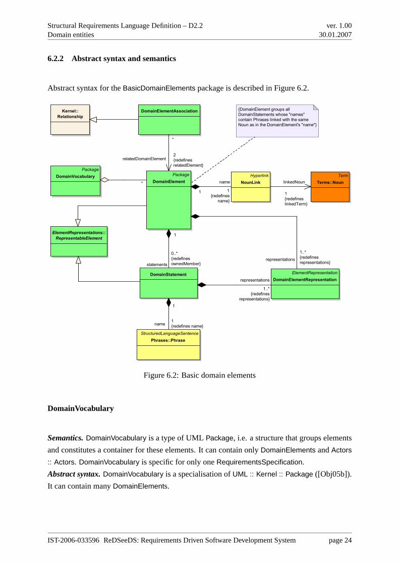
6.2.2 Abstract syntax and semantics
Abstract syntax for theBasicDomainElements package is described in Figure 6.2.
Package
DomainVocabulary Package
DomainElement
Hyperlink
NounLink
DomainStatement
Term
Terms::Noun
ElementRepresentations::
RepresentableElement
DomainElementAssociationKernel::
Relationship
StructuredLanguageSentence
Phrases::Phrase
{DomainElement groups all
DomainStatements whose "names"
contain Phrases linked with the same
Noun as in the DomainElement's "name"}
ElementRepresentation
DomainElementRepresentation
* name
1
{redefines
name}
1
linkedNoun
1
{redefines
linkedTerm}
statements
0..*
{redefines
ownedMember}
1
*
relatedDomainElement2
{redefines
relatedElement}
name1
{redefines name}
1
representations
1..*
{redefines
representations}
representations
1..*
{redefines
representations}
Figure 6.2: Basic domain elements
DomainVocabulary
Semantics.DomainVocabulary is a type of UMLPackage, i.e. a structure that groups elements
and constitutes a container for these elements. It can contain onlyDomainElements andActors
:: Actors. DomainVocabulary is specific for only oneRequirementsSpecification.
Abstract syntax.DomainVocabulary is a specialisation ofUML :: Kernel :: Package ([Obj05b]).
It can contain manyDomainElements.
IST-2006-033596 ReDSeeDS: Requirements Driven Software Development System page 24
Structural Requirements Language Definition – D2.2Domain entities
ver. 1.0030.01.2007
DomainElement
Semantics.This is a type of a UMLPackage, i.e. a structure that groups elements and con-
stitutes a container for these elements.DomainElement contains allDomainStatements whose
‘name’s containPhrases linked with the sameTerms :: Noun as in theDomainElement’s ‘name’.
DomainElements can be related.
Abstract syntax.DomainElement is a specialisation ofUML :: Kernel :: Package ([Obj05b]) and
ElementRepresentations :: RepresentableElement. It redefinesownedMember. Owned mem-
bers for theDomainElement must beDomainStatements. It also redefines‘name’ with NounLink
and representations withDomainElementRepresentation. DomainElements can be related only
by DomainElementAssociation.
DomainElementRepresentation
Semantics.This is a representation for elements from packageBasicDomainElements (Domain-
Statement andDomainElement) in form of wiki-like description. It contains set of hyperlinked
sentences derived fromRepresentableElements :: ElementRepresentation.
Abstract syntax.DomainElementRepresentation is concrete specialisation ofRepresentableEle-
ments :: ElementRepresentation. It overridesrepresentations for classes from packageBasic-
DomainElements.
DomainElementAssociation
Semantics.DomainElementAssociation denotes relationships between twoDomainElements.
Abstract syntax.DomainElementAssociation is a kind ofKernel :: Relationship [Obj05b]. It
connects twoDomainElements by redefiningrelatedElement with relatedDomainElement. This
relationship is not directed.
NounLink
Semantics. NounLink is a hyperlink that points to theTerms :: Noun used for namingDo-
mainElements.
Abstract syntax.A NounLink is a kind of aBasicRepresentations :: Hyperlink. It is associated
with Terms :: Noun andDomainElement.
IST-2006-033596 ReDSeeDS: Requirements Driven Software Development System page 25
Structural Requirements Language Definition – D2.2Domain entities
ver. 1.0030.01.2007
DomainStatement
Semantics. DomainStatement is a wiki-like description of an element of the domain of the
system to be developed with its context - noun with modifiers, verbs and other nouns.Domain-
Statements are grouped inDomainElement.
Abstract syntax. DomainStatement is a specialization ofElementRepresentations :: Repre-
sentableElement. It redefines‘name’ with Phrases :: Phrase. DomainStatements are contained
in DomainElement.
6.2.3 Concrete syntax and examples
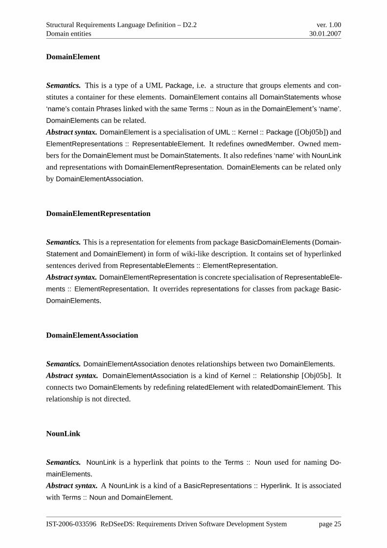
DomainVocabulary.The concrete syntax is similar toKernel :: Package, described in the UML
Superstructure (in [Obj05b], paragraph 7.3.37, page 104): “A package is shown as a large rec-
tangle with a small rectangle (a ’tab’) attached to the left side of the top of the large rectangle.
(...) Members may also be shown by branching lines to member elements, drawn outside the
package. A plus sign (+) within a circle is drawn at the end attached to the namespace (pack-
age). (...)” In addition to the above Kernel :: Package description, name ofDomainVocabulary
package is inside rectangle situated in the center of the large rectangle. It can also be presented
in a tree structure with a minimized icon. See Figure 6.3 for examples of concrete syntax in a
Package Diagram and in a Project Tree structure with a minimized icon, respectively.
Figure 6.3: DomainVocabulary example, normal and tree view
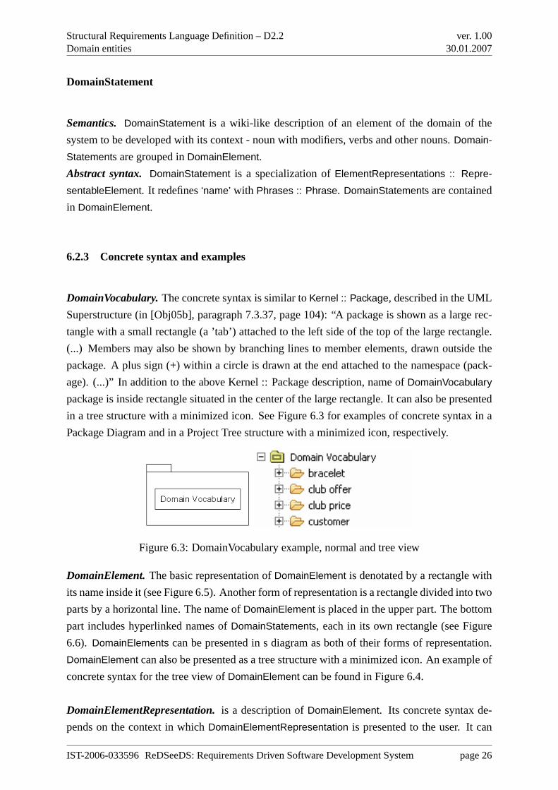
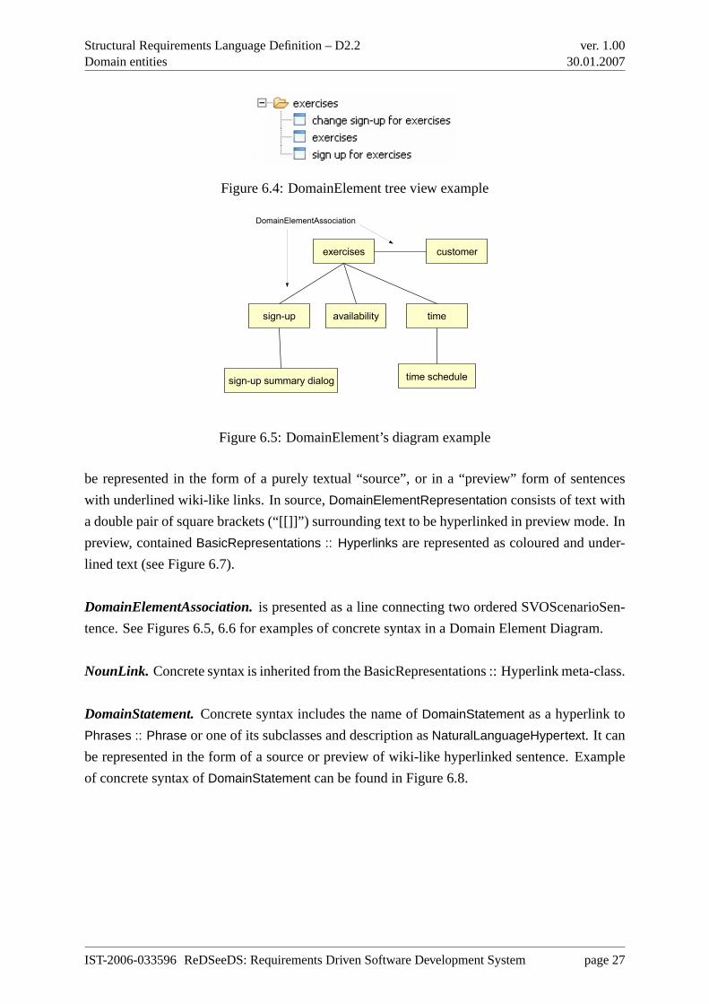
DomainElement.The basic representation ofDomainElement is denotated by a rectangle with
its name inside it (see Figure 6.5). Another form of representation is a rectangle divided into two
parts by a horizontal line. The name ofDomainElement is placed in the upper part. The bottom
part includes hyperlinked names ofDomainStatements, each in its own rectangle (see Figure
6.6). DomainElements can be presented in s diagram as both of their forms of representation.
DomainElement can also be presented as a tree structure with a minimized icon. An example of
concrete syntax for the tree view ofDomainElement can be found in Figure 6.4.
DomainElementRepresentation.is a description ofDomainElement. Its concrete syntax de-
pends on the context in whichDomainElementRepresentation is presented to the user. It can
IST-2006-033596 ReDSeeDS: Requirements Driven Software Development System page 26
Structural Requirements Language Definition – D2.2Domain entities
ver. 1.0030.01.2007
Figure 6.4: DomainElement tree view example
customer
time schedule
exercises
sign-up
sign-up summary dialog
timeavailability
DomainElementAssociation
Figure 6.5: DomainElement’s diagram example
be represented in the form of a purely textual “source”, or in a “preview” form of sentences
with underlined wiki-like links. In source,DomainElementRepresentation consists of text with
a double pair of square brackets (“[[]]”) surrounding text to be hyperlinked in preview mode. In
preview, containedBasicRepresentations :: Hyperlinks are represented as coloured and under-
lined text (see Figure 6.7).
DomainElementAssociation.is presented as a line connecting two ordered SVOScenarioSen-
tence. See Figures 6.5, 6.6 for examples of concrete syntax in a Domain Element Diagram.
NounLink. Concrete syntax is inherited from the BasicRepresentations :: Hyperlink meta-class.
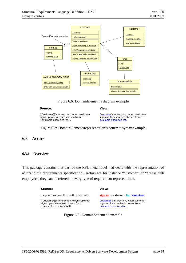
DomainStatement.Concrete syntax includes the name ofDomainStatement as a hyperlink to
Phrases :: Phrase or one of its subclasses and description asNaturalLanguageHypertext. It can
be represented in the form of a source or preview of wiki-like hyperlinked sentence. Example
of concrete syntax ofDomainStatement can be found in Figure 6.8.
IST-2006-033596 ReDSeeDS: Requirements Driven Software Development System page 27
Structural Requirements Language Definition – D2.2Domain entities
ver. 1.0030.01.2007
sign-up summary dialog
sign-up summary dialog
show sign-up summary dialog
sign-up summary dialog
sign-up summary dialog
show sign-up summary dialog
exercises
cyclic exercises
sporadic exercises
check availability of exercises
submit sign-up for exercises
want to sign up for exercises
sign up customer for exercises
exercises
exercises
cyclic exercises
sporadic exercises
check availability of exercises
submit sign-up for exercises
want to sign up for exercises
sign up customer for exercises
exercises
customer
customer
returning customer
sign up customer
customer
customer
returning customer
sign up customer
time schedule
time schedule
choose time from time schedule
time schedule
time schedule
choose time from time schedule
time
time
choose time
time
time
choose time
availability
availability
check availability
availability
availability
check availability
sign-up
sign-up
submit sign-up
DomainElementAssociation
Figure 6.6: DomainElement’s diagram example
Source: View:
[[Customer]]'s interaction, when customer Customer's interaction, when customer signs up for exercises chosen from signs up for exercises chosen from [[available exercises list]]. available exercises list.
Figure 6.7: DomainElementRepresentation’s concrete syntax example
6.3 Actors
6.3.1 Overview
This package contains that part of the RSL metamodel that deals with the representation of
actors in the requirements specification. Actors are for instance “customer” or “fitness club
employee”, they can be refered in every type of requirement representation.
Source: View:
[[sign up customer]] : [[for]] : [[exercises]] sign up : customer : for : exercises
[[Customer]]'s interaction, when customer Customer's interaction, when customer signs up for exercises chosen from signs up for exercises chosen from [[available exercises list]]. available exercises list.
Figure 6.8: DomainStatement example
IST-2006-033596 ReDSeeDS: Requirements Driven Software Development System page 28
Structural Requirements Language Definition – D2.2Domain entities
ver. 1.0030.01.2007
6.3.2 Abstract syntax and semantics
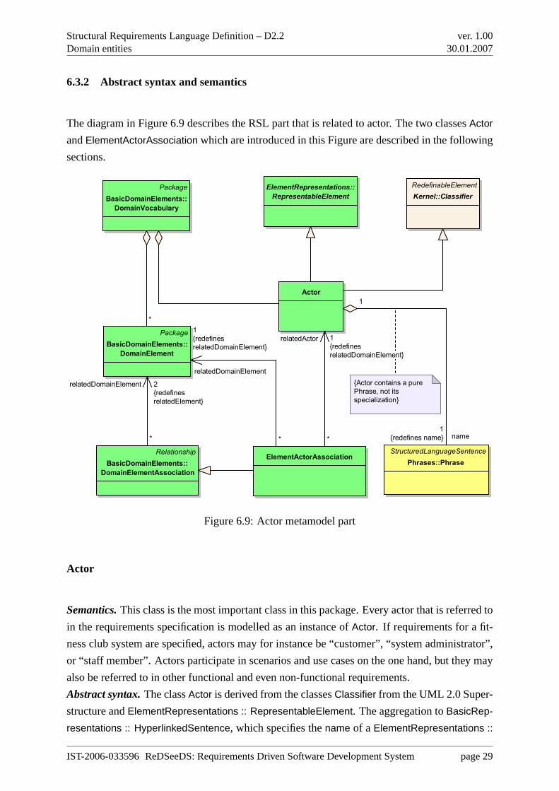
The diagram in Figure 6.9 describes the RSL part that is related to actor. The two classesActor
andElementActorAssociation which are introduced in this Figure are described in the following
sections.
Actor
Package
BasicDomainElements::
DomainVocabulary
ElementRepresentations::
RepresentableElement
Package
BasicDomainElements::
DomainElement
StructuredLanguageSentence
Phrases::PhraseElementActorAssociation
{Actor contains a pure
Phrase, not its
specialization}
RedefinableElement
Kernel::Classifier
Relationship
BasicDomainElements::
DomainElementAssociation
*
name1
{redefines name}
1
*
relatedDomainElement
1
{redefines
relatedDomainElement}
*
relatedActor 1
{redefines
relatedDomainElement}
*
relatedDomainElement 2
{redefines
relatedElement}
Figure 6.9: Actor metamodel part
Actor
Semantics.This class is the most important class in this package. Every actor that is referred to
in the requirements specification is modelled as an instance ofActor. If requirements for a fit-
ness club system are specified, actors may for instance be “customer”, “system administrator”,
or “staff member”. Actors participate in scenarios and use cases on the one hand, but they may
also be referred to in other functional and even non-functional requirements.
Abstract syntax.The classActor is derived from the classesClassifier from the UML 2.0 Super-
structure andElementRepresentations :: RepresentableElement. The aggregation toBasicRep-
resentations :: HyperlinkedSentence, which specifies thename of a ElementRepresentations ::
IST-2006-033596 ReDSeeDS: Requirements Driven Software Development System page 29
Structural Requirements Language Definition – D2.2Domain entities
ver. 1.0030.01.2007
RepresentableElement is redefined, thus the name of anActor may only be aPhrases :: Phrase.
The constraint is added to this redefined aggregation because an actor’s name should be for ex-
ample “a customer” but not aPhrases :: VerbPhrase like “take”. Actors can be associated with
other elements throughElementActorAssociations, as described below SinceActors are domain
specific, they are part of theBasicDomainElements :: DomainVocabulary.
ElementActorAssociation
Semantics.An ElementActorAssociation models the relationship between anActor and other
domain specific entities in theBasicDomainElements :: DomainVocabulary.
Abstract syntax.ElementActorAssociations base-class isBasicDomainElements :: DomainEle-
mentAssociation, which models the relationship between any twoBasicDomainElements :: Do-
mainElements. Since theElementActorAssociation should only be used to model the relation-
ship between oneActor and oneBasicDomainElements :: DomainElement, the inherited associ-
ation toBasicDomainElements :: DomainElement is redefined as two associations, one toActor
and one toBasicDomainElements :: DomainElement, each of them needing exactly one instance
of Actor perBasicDomainElements :: DomainElement to participate.
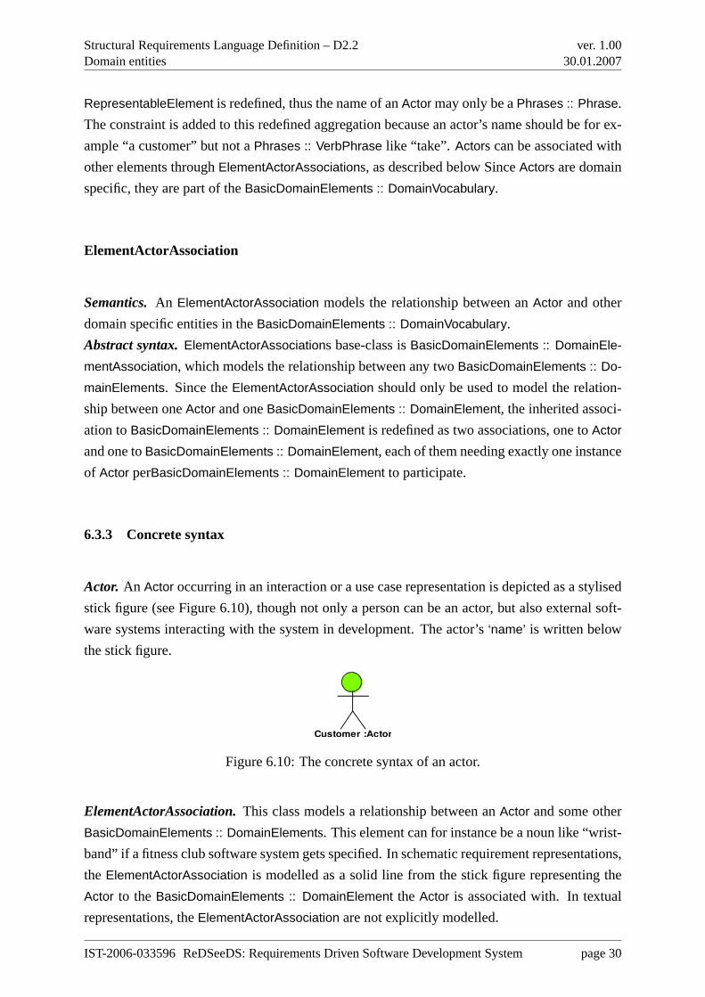
6.3.3 Concrete syntax
Actor. An Actor occurring in an interaction or a use case representation is depicted as a stylised
stick figure (see Figure 6.10), though not only a person can be an actor, but also external soft-
ware systems interacting with the system in development. The actor’s‘name’ is written below
the stick figure.
Customer :Actor
Figure 6.10: The concrete syntax of an actor.
ElementActorAssociation.This class models a relationship between anActor and some other
BasicDomainElements :: DomainElements. This element can for instance be a noun like “wrist-
band” if a fitness club software system gets specified. In schematic requirement representations,
the ElementActorAssociation is modelled as a solid line from the stick figure representing the
Actor to theBasicDomainElements :: DomainElement the Actor is associated with. In textual
representations, theElementActorAssociation are not explicitly modelled.
IST-2006-033596 ReDSeeDS: Requirements Driven Software Development System page 30
Structural Requirements Language Definition – D2.2Domain entities
ver. 1.0030.01.2007
6.4 System representations
6.4.1 Overview
This package contains the part of the RSL meta-model that deals with the representation of
the system under development and its components in the requirements specification. If the
system under development is the fitness club software system, its components are for instance
“terminal” or “database”.
6.4.2 Abstract syntax and semantics
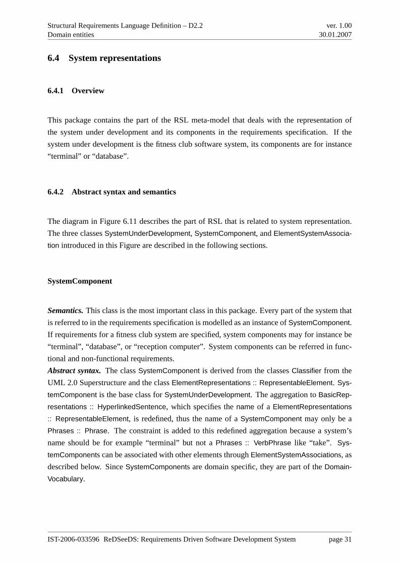
The diagram in Figure 6.11 describes the part of RSL that is related to system representation.
The three classesSystemUnderDevelopment, SystemComponent, andElementSystemAssocia-
tion introduced in this Figure are described in the following sections.
SystemComponent
Semantics.This class is the most important class in this package. Every part of the system that
is referred to in the requirements specification is modelled as an instance ofSystemComponent.
If requirements for a fitness club system are specified, system components may for instance be
“terminal”, “database”, or “reception computer”. System components can be referred in func-
tional and non-functional requirements.
Abstract syntax.The classSystemComponent is derived from the classesClassifier from the
UML 2.0 Superstructure and the classElementRepresentations :: RepresentableElement. Sys-
temComponent is the base class forSystemUnderDevelopment. The aggregation toBasicRep-
resentations :: HyperlinkedSentence, which specifies thename of a ElementRepresentations
:: RepresentableElement, is redefined, thus the name of aSystemComponent may only be a
Phrases :: Phrase. The constraint is added to this redefined aggregation because a system’s
name should be for example “terminal” but not aPhrases :: VerbPhrase like “take”. Sys-
temComponents can be associated with other elements throughElementSystemAssociations, as
described below. SinceSystemComponents are domain specific, they are part of theDomain-
Vocabulary.
IST-2006-033596 ReDSeeDS: Requirements Driven Software Development System page 31
Structural Requirements Language Definition – D2.2Domain entities
ver. 1.0030.01.2007
SystemComponent
ElementRepresentations::
RepresentableElement
Package
BasicDomainElements::
DomainVocabulary
SystemUnderDevelopmentPackage
BasicDomainElements::
DomainElement
RedefinableElement
Kernel::Classifier
StructuredLanguageSentence
Phrases::Phrase
Relationship
BasicDomainElements::
DomainElementAssociation
ElementSystemAssociation
SystemComponent
contains a pure Phrase,
not its specialization
+component
0..*
0..1
*
*
+relatedDomainElement2
{redefines
relatedElement}
*
+relatedDomainElement
1
{redefines
relatedDomainElement}
*
+relatedSystemComponent
1
{redefines
relatedDomainElement}
+name
1
{redefines name}
Figure 6.11: System representations
SystemUnderDevelopment
Semantics.The classSystemUnderDevelopment represents the whole system under develop-
ment as a black box. It can be used in all kinds of requirement representations, especially if
requirements on all parts of the system are modelled or if modelling is on a coarse granularity.
Abstract syntax.SystemUnderDevelopment is derived fromSystemComponent, so it inherits
all associations fromSystemComponent. SinceSystemUnderDevelopment depicts the whole
system under development, it may not be part of anotherSystemComponent, as the constraint
in the diagram indicates. Another restriction is the cardinality at the aggregation toDomainVo-
cabulary, since there is exactly oneSystemUnderDevelopment during the requirements specifi-
cation process, it must be exactly oneSystemUnderDevelopment in theDomainVocabulary.
IST-2006-033596 ReDSeeDS: Requirements Driven Software Development System page 32
Structural Requirements Language Definition – D2.2Domain entities
ver. 1.0030.01.2007
ElementSystemAssociation
Semantics.An ElementSystemAssociation models the relationship between aSystemCompo-
nent and other domain specific entities in theDomainVocabulary.
Abstract syntax.The base class ofElementSystemAssociation is the classDomainElementAs-
sociation, which models the relationship between any twoDomainElements. Since theEle-
mentSystemAssociation should only be used to model the relationship between oneSystem and
oneDomainElement, the inherited association toDomainElement is redefined as two associa-
tions, one toSystem and one toDomainElement, each of them needing exactly one instance of
System perDomainElement to participate.
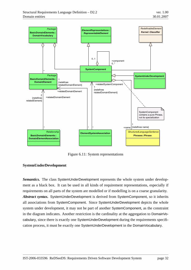
6.4.3 Concrete syntax
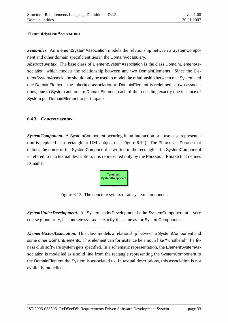
SystemComponent.A SystemComponent occuring in an interaction or a use case representa-
tion is depicted as a rectanglular UML object (see Figure 6.12). ThePhrases :: Phrase that
defines thename of theSystemComponent is written in the rectangle. If aSystemComponent
is refered to in a textual description, it is represented only by thePhrases :: Phrase that defines
its name.
Terminal :
SystemComponent
Reception :
SystemComponent
Customer :ActorEmployee :Actor
asksForHelp
sendHelpRequest
showsHelpRequest
acceptsHelpRequest
sendRequestAccepted
informCustomer
Figure 6.12: The concrete syntax of an system component.
SystemUnderDevelopment.As SystemUnderDevelopment is theSystemComponent at a very
coarse granularity, its concrete syntax is exactly the same as forSystemComponent.
ElementActorAssociation.This class models a relationship between aSystemComponent and
some otherDomainElements. This element can for instance be a noun like “wristband” if a fit-
ness club software system gets specified. In a schematic representation, theElementSystemAs-
sociation is modelled as a solid line from the rectangle representing theSystemComponent to
theDomainElement theSystem is associated to. In textual descriptions, this association is not
explicitly modelled.
IST-2006-033596 ReDSeeDS: Requirements Driven Software Development System page 33
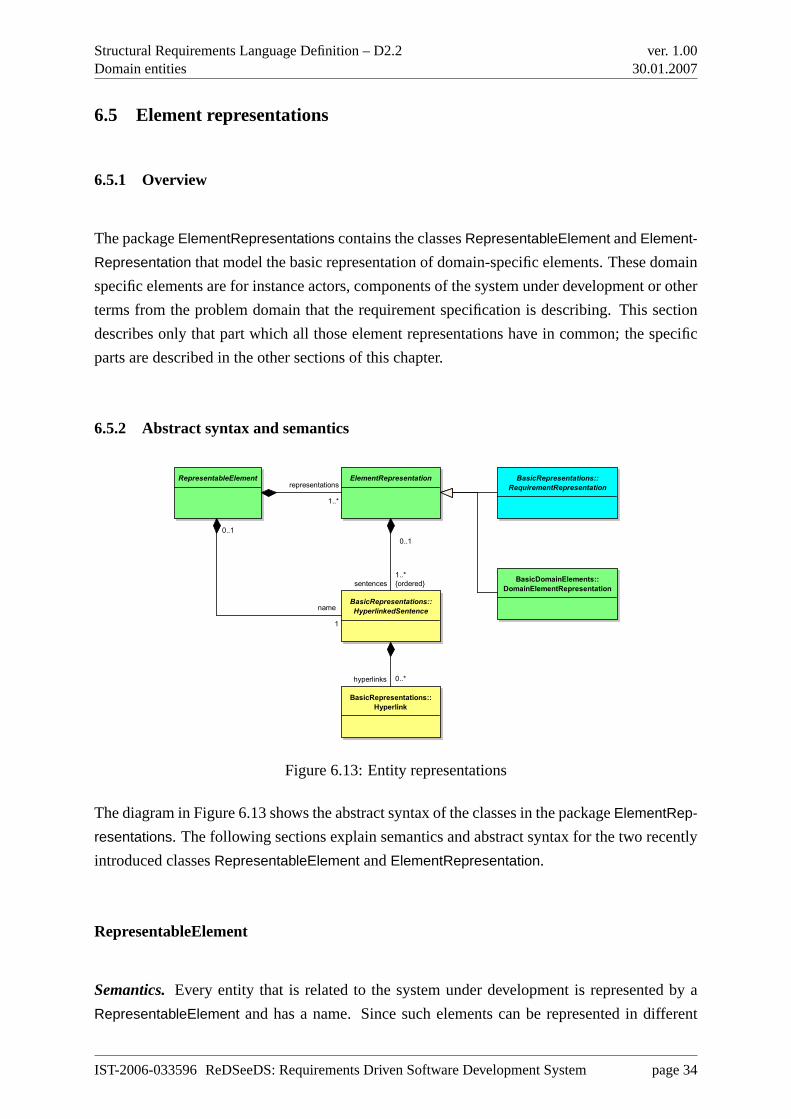
Structural Requirements Language Definition – D2.2Domain entities
ver. 1.0030.01.2007
6.5 Element representations
6.5.1 Overview
The packageElementRepresentations contains the classesRepresentableElement andElement-
Representation that model the basic representation of domain-specific elements. These domain
specific elements are for instance actors, components of the system under development or other
terms from the problem domain that the requirement specification is describing. This section
describes only that part which all those element representations have in common; the specific
parts are described in the other sections of this chapter.
6.5.2 Abstract syntax and semantics
RepresentableElement ElementRepresentation
BasicRepresentations::
HyperlinkedSentence
BasicRepresentations::
Hyperlink
BasicRepresentations::
RequirementRepresentation
BasicDomainElements::
DomainElementRepresentation
representations
1..*
name
1
0..1
sentences
1..*
{ordered}
0..1
hyperlinks 0..*
Figure 6.13: Entity representations
The diagram in Figure 6.13 shows the abstract syntax of the classes in the packageElementRep-
resentations. The following sections explain semantics and abstract syntax for the two recently
introduced classesRepresentableElement andElementRepresentation.
RepresentableElement
Semantics.Every entity that is related to the system under development is represented by a
RepresentableElement and has a name. Since such elements can be represented in different
IST-2006-033596 ReDSeeDS: Requirements Driven Software Development System page 34
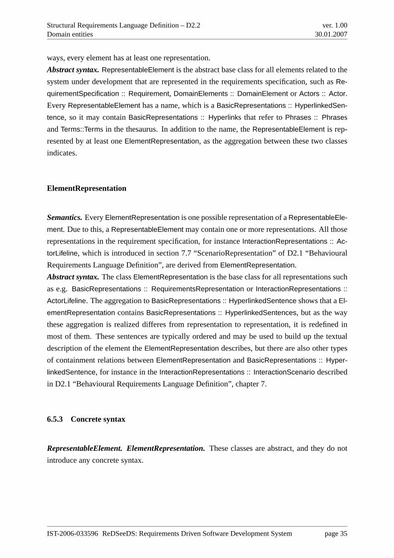
Structural Requirements Language Definition – D2.2Domain entities
ver. 1.0030.01.2007
ways, every element has at least one representation.
Abstract syntax.RepresentableElement is the abstract base class for all elements related to the
system under development that are represented in the requirements specification, such asRe-
quirementSpecification :: Requirement, DomainElements :: DomainElement or Actors :: Actor.
EveryRepresentableElement has a name, which is aBasicRepresentations :: HyperlinkedSen-
tence, so it may containBasicRepresentations :: Hyperlinks that refer toPhrases :: Phrases
andTerms::Terms in the thesaurus. In addition to the name, theRepresentableElement is rep-
resented by at least oneElementRepresentation, as the aggregation between these two classes
indicates.
ElementRepresentation
Semantics.EveryElementRepresentation is one possible representation of aRepresentableEle-
ment. Due to this, aRepresentableElement may contain one or more representations. All those
representations in the requirement specification, for instanceInteractionRepresentations :: Ac-
torLifeline, which is introduced in section 7.7 “ScenarioRepresentation” of D2.1 “Behavioural
Requirements Language Definition”, are derived fromElementRepresentation.
Abstract syntax.The classElementRepresentation is the base class for all representations such
as e.g.BasicRepresentations :: RequirementsRepresentation or InteractionRepresentations ::
ActorLifeline. The aggregation toBasicRepresentations :: HyperlinkedSentence shows that aEl-
ementRepresentation containsBasicRepresentations :: HyperlinkedSentences, but as the way
these aggregation is realized differes from representation to representation, it is redefined in
most of them. These sentences are typically ordered and may be used to build up the textual
description of the element theElementRepresentation describes, but there are also other types
of containment relations betweenElementRepresentation andBasicRepresentations :: Hyper-
linkedSentence, for instance in theInteractionRepresentations :: InteractionScenario described
in D2.1 “Behavioural Requirements Language Definition”, chapter 7.
6.5.3 Concrete syntax
RepresentableElement. ElementRepresentation.These classes are abstract, and they do not
introduce any concrete syntax.
IST-2006-033596 ReDSeeDS: Requirements Driven Software Development System page 35
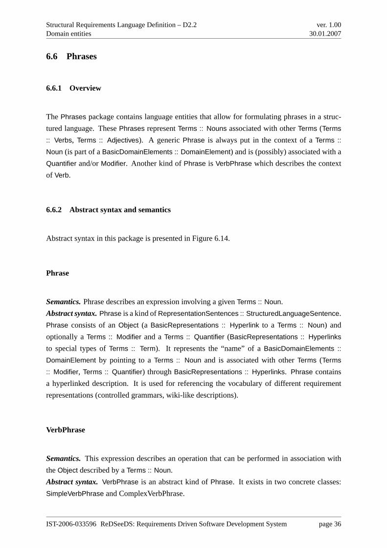
Structural Requirements Language Definition – D2.2Domain entities
ver. 1.0030.01.2007
6.6 Phrases
6.6.1 Overview
ThePhrases package contains language entities that allow for formulating phrases in a struc-
tured language. ThesePhrases representTerms :: Nouns associated with otherTerms (Terms
:: Verbs, Terms :: Adjectives). A genericPhrase is always put in the context of aTerms ::
Noun (is part of aBasicDomainElements :: DomainElement) and is (possibly) associated with a
Quantifier and/orModifier. Another kind ofPhrase is VerbPhrase which describes the context
of Verb.
6.6.2 Abstract syntax and semantics
Abstract syntax in this package is presented in Figure 6.14.
Phrase
Semantics.Phrase describes an expression involving a givenTerms :: Noun.
Abstract syntax.Phrase is a kind ofRepresentationSentences :: StructuredLanguageSentence.
Phrase consists of anObject (a BasicRepresentations :: Hyperlink to a Terms :: Noun) and
optionally aTerms :: Modifier and aTerms :: Quantifier (BasicRepresentations :: Hyperlinks
to special types ofTerms :: Term). It represents the “name” of aBasicDomainElements ::
DomainElement by pointing to aTerms :: Noun and is associated with otherTerms (Terms
:: Modifier, Terms :: Quantifier) throughBasicRepresentations :: Hyperlinks. Phrase contains
a hyperlinked description. It is used for referencing the vocabulary of different requirement
representations (controlled grammars, wiki-like descriptions).
VerbPhrase
Semantics.This expression describes an operation that can be performed in association with
theObject described by aTerms :: Noun.
Abstract syntax.VerbPhrase is an abstract kind ofPhrase. It exists in two concrete classes:
SimpleVerbPhrase and ComplexVerbPhrase.
IST-2006-033596 ReDSeeDS: Requirements Driven Software Development System page 36
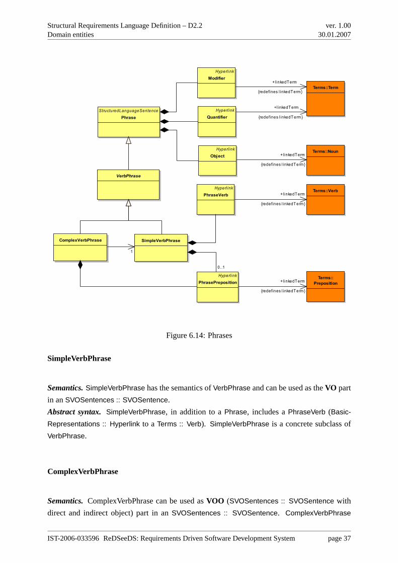
Structural Requirements Language Definition – D2.2Domain entities
ver. 1.0030.01.2007
StructuredLanguageSentencePhrase
ComplexVerbPhrase SimpleVerbPhrase
Terms::Term
Terms::Noun
VerbPhrase
Terms::Verb
Terms::Preposition
Hyperl inkModifier
Hyperl inkQuantifier
Hyperl inkObject
Hyperl inkPhraseVerb
Hyperl inkPhrasePreposition
+l inkedT erm
{redefines l inkedT erm }
0..1
+l inkedT erm
{redefines l inkedT erm }
+l inkedT erm
{redefines l inkedT erm }
+l inkedT erm
{redefines l inkedT erm }
+l inkedT erm
{redefines l inkedT erm }
1
Figure 6.14: Phrases
SimpleVerbPhrase
Semantics.SimpleVerbPhrase has the semantics ofVerbPhrase and can be used as theVO part
in anSVOSentences :: SVOSentence.
Abstract syntax. SimpleVerbPhrase, in addition to aPhrase, includes aPhraseVerb (Basic-
Representations :: Hyperlink to a Terms :: Verb). SimpleVerbPhrase is a concrete subclass of
VerbPhrase.
ComplexVerbPhrase
Semantics.ComplexVerbPhrase can be used asVOO (SVOSentences :: SVOSentence with
direct and indirect object) part in anSVOSentences :: SVOSentence. ComplexVerbPhrase
IST-2006-033596 ReDSeeDS: Requirements Driven Software Development System page 37
Structural Requirements Language Definition – D2.2Domain entities
ver. 1.0030.01.2007
describes a behavioural relation between a direct and an indirect object.
Abstract syntax.ComplexVerbPhrase extendsSimpleVerbPhrase with an additionalTerms ::
Noun (indirect object). It is a kind ofVerbPhrase pointing to the other BasicDomainElements
:: DomainElements’s SimpleVerbPhrase. It includes also aPhrasePreposition. ComplexVerb-
Phrase is a concrete subclass ofVerbPhrase.
Modifier
Semantics.A Modifier combines withObject and indicates how it should be interpreted in the
surrounding context. In this way it creates a Phrase that distinguishes thisObject’s meaning
from its main vocabulary entry.
Abstract syntax.Modifier is a kind of aBasicRepresentations :: Hyperlink. It points to theTerms
:: Term used as aModifier in a given Phrase.
Quantifier
Semantics.A Quantifier combines withObject and indicates how they should be interpreted in
the surrounding context in terms of quantity and variability, that is the extent to which Noun
holds over a range of things. In this way it creates a Phrase that distinguishes thisObject’s
meaning from it’s main vocabulary entry.
Abstract syntax.Quantifier is a kind of aBasicRepresentations :: Hyperlink. It points to the
Term :: Term used as aQuantifier in a given Phrase.
Object
Semantics.An Object is a type of aBasicRepresentations :: Hyperlink that points to theTerms
:: Noun specific for thisObject’s Phrase.
Abstract syntax.Object is a kind of aBasicRepresentations :: Hyperlink.
IST-2006-033596 ReDSeeDS: Requirements Driven Software Development System page 38
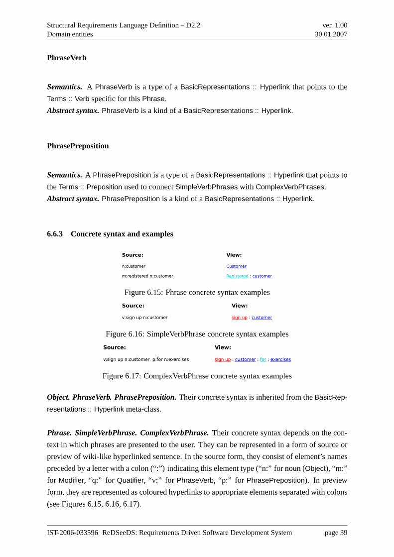
Structural Requirements Language Definition – D2.2Domain entities
ver. 1.0030.01.2007
PhraseVerb
Semantics.A PhraseVerb is a type of aBasicRepresentations :: Hyperlink that points to the
Terms :: Verb specific for thisPhrase.
Abstract syntax.PhraseVerb is a kind of aBasicRepresentations :: Hyperlink.
PhrasePreposition
Semantics.A PhrasePreposition is a type of aBasicRepresentations :: Hyperlink that points to
theTerms :: Preposition used to connectSimpleVerbPhrases with ComplexVerbPhrases.
Abstract syntax.PhrasePreposition is a kind of aBasicRepresentations :: Hyperlink.
6.6.3 Concrete syntax and examples
Source: View:
n:customer Customer
m:registered n:customer Registered : customer
Figure 6.15: Phrase concrete syntax examples
Source: View:
v:sign up n:customer sign up : customer
Figure 6.16: SimpleVerbPhrase concrete syntax examples
Source: View:
v:sign up n:customer p:for n:exercises sign up : customer : for : exercises
Figure 6.17: ComplexVerbPhrase concrete syntax examples
Object. PhraseVerb. PhrasePreposition.Their concrete syntax is inherited from theBasicRep-
resentations :: Hyperlink meta-class.
Phrase. SimpleVerbPhrase. ComplexVerbPhrase.Their concrete syntax depends on the con-
text in which phrases are presented to the user. They can be represented in a form of source or
preview of wiki-like hyperlinked sentence. In the source form, they consist of element’s names
preceded by a letter with a colon (“:”) indicating this element type (“n:” for noun (Object), “m:”
for Modifier, “q:” for Quatifier, “v:” for PhraseVerb, “p:” for PhrasePreposition). In preview
form, they are represented as coloured hyperlinks to appropriate elements separated with colons
(see Figures 6.15, 6.16, 6.17).
IST-2006-033596 ReDSeeDS: Requirements Driven Software Development System page 39
Structural Requirements Language Definition – D2.2Domain entities
ver. 1.0030.01.2007
6.7 Terms
6.7.1 Overview
This package describesTerm and its relationship toThesaurus. Thesaurus is a kind of highly
structured conceptual dictionary, common for all vocabularies. It contains morphological infor-
mation of terms, with their forms (cases, inflections, etc.) and semantic information. Currently
theTermSpecialisationRelation as well asHasSynonym andHasHomonym relations are seen as
the main semantic information.
TheTermSpecialisationRelation structures the terms in a taxonomical hierarchy. This semantic
definition is organisation-specific and is specified by extending the term structure (see Figures
6.20 and 6.21 for an example).
Every term is a distinguished part of speech. Note that “term” is not necessarily a single word
(eg. some modal verbs – see note on the Diagram 6.18). We also treat phrasal verbs as Verb
class objects.Terms from Thesaurus are used for buildingPhrases.
6.7.2 Abstract syntax and semantics
Figure 6.18 shows the specialisation hierarchy of the different types ofTerms, which areCon-
ditionalConjunction, ModalVerb, Verb, Noun, Modifier, Quantifier and Preposition. Addition-
ally, this figure introduces two bi-directional relations that can be defined between twoTerms,
namelyHasHomonym andHasSynonym.
Figure 6.19 also contains all the above mentioned specialisations ofTerm. This figure focuses on
the relationships that can be defined between two terms of the same type (only in between two
Nouns, between twoVerbs, etc.). All relations are specialisations ofTermSpecialisationRelation
and thus define a directed taxonomic relation.
Figures 6.20 and 6.21 show the abstract syntax of a thesaurus with domain-specific extensions
(for ProDV related terms in this case). Figure 6.20 depicts the noun related part of the thesaurus,
while Figure 6.21 shows the verb related part respectively.
IST-2006-033596 ReDSeeDS: Requirements Driven Software Development System page 40
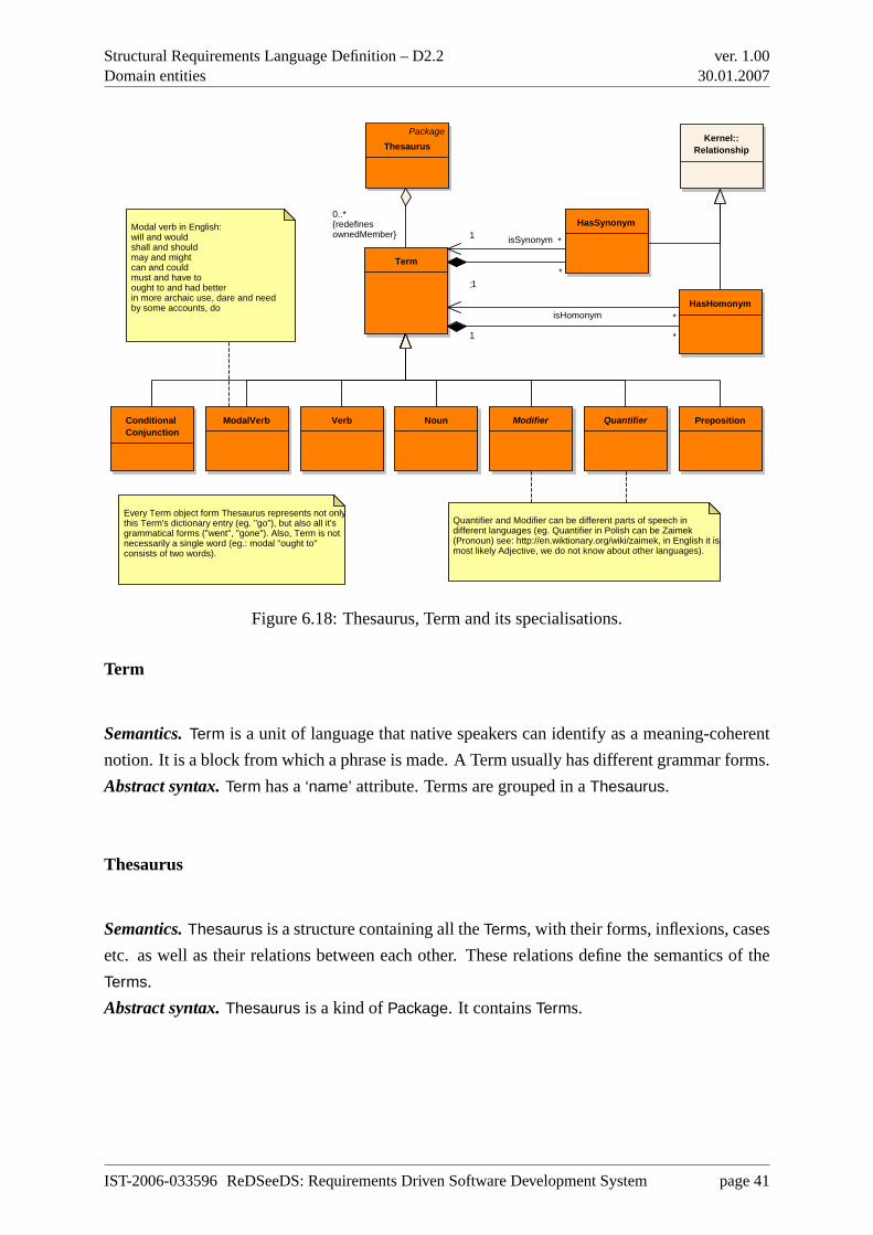
Structural Requirements Language Definition – D2.2Domain entities
ver. 1.0030.01.2007
Verb Noun Quantifier
Term
PrepositionModalVerb
Modal verb in English: will and wouldshall and shouldmay and mightcan and couldmust and have toought to and had betterin more archaic use, dare and needby some accounts, do
Every Term object form Thesaurus represents not onlythis Term's dictionary entry (eg. "go"), but also all it's grammatical forms ("went", "gone"). Also, Term is not necessarily a single word (eg.: modal "ought to" consists of two words).
Modifier
Quantifier and Modifier can be different parts of speech in different languages (eg. Quantifier in Polish can be Zaimek (Pronoun) see: http://en.wiktionary.org/wiki/zaimek, in English it ismost likely Adjective, we do not know about other languages).
PackageThesaurus
Conditional Conjunction
HasHomonym
HasSynonym
Kernel::Relationship
*1
*1
1 isSynonym *
0..*{redefinesownedMember}
1
isHomonym *
Figure 6.18: Thesaurus, Term and its specialisations.
Term
Semantics.Term is a unit of language that native speakers can identify as a meaning-coherent
notion. It is a block from which a phrase is made. A Term usually has different grammar forms.
Abstract syntax.Term has a‘name’ attribute. Terms are grouped in aThesaurus.
Thesaurus
Semantics.Thesaurus is a structure containing all theTerms, with their forms, inflexions, cases
etc. as well as their relations between each other. These relations define the semantics of the
Terms.
Abstract syntax.Thesaurus is a kind ofPackage. It containsTerms.
IST-2006-033596 ReDSeeDS: Requirements Driven Software Development System page 41
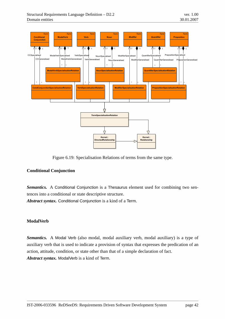
Structural Requirements Language Definition – D2.2Domain entities
ver. 1.0030.01.2007
Term
Verb
Term
Noun
Term
Quantifier
Term
Preposition
Term
ModalVerb
Term
Modifier
Term
Conditional
Conjunction
NounSpecialisationRelation
VerbSpecialisationRelation
ModalVerbSpecialisationRelation
ModifierSpecialisationRelation
QuantifierSpecialisationRelation
PrepositionSpecialisationRelationCondConjunctionSpecialisationRelation
TermSpecialisationRelation
Kernel::
DirectedRelationship
Kernel::
Relationship
*
ModalVerbGeneralised
1
*
CCGeneralised
1
*
PrepositionGeneralised
1
*
QuantifierGeneralised
11
VerbSpecialised
* *
VerbGeneralised
1
*
NounGeneralised
11
CCSpecialised
*
1
ModifierSpecialised
*
1
ModalVerbSpecialised
*
1
PrepositionSpecialised
*
1
QuantifierSpecialised
*
1
NounSpecialised
*
*
ModifierGeneralised
1
Figure 6.19: Specialisation Relations of terms from the same type.
Conditional Conjunction
Semantics. A Conditional Conjunction is a Thesaurus element used for combining two sen-
tences into a conditional or state descriptive structure.
Abstract syntax.Conditional Conjunction is a kind of aTerm.
ModalVerb
Semantics. A Modal Verb (also modal, modal auxiliary verb, modal auxiliary) is a type of
auxiliary verb that is used to indicate a provision of syntax that expresses the predication of an
action, attitude, condition, or state other than that of a simple declaration of fact.
Abstract syntax.ModalVerb is a kind ofTerm.
IST-2006-033596 ReDSeeDS: Requirements Driven Software Development System page 42
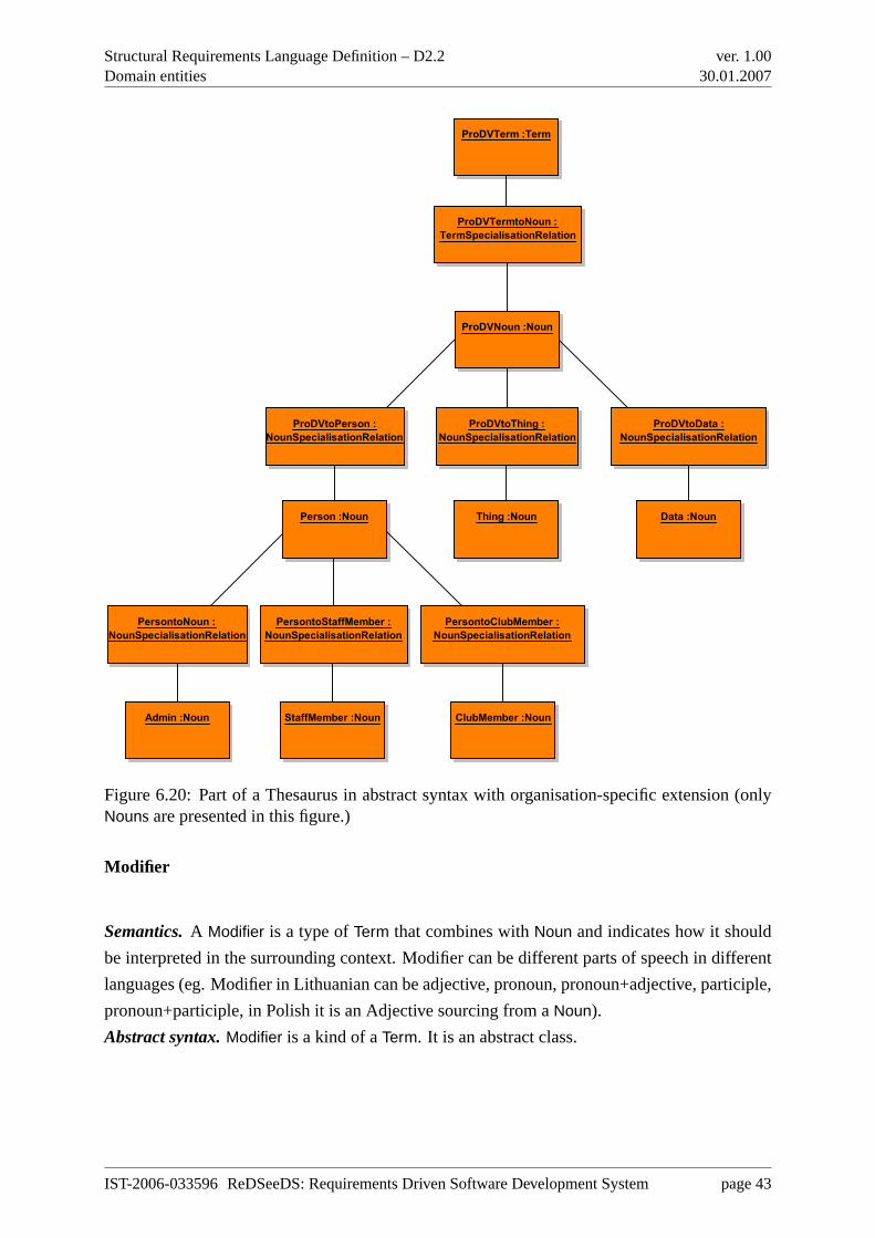
Structural Requirements Language Definition – D2.2Domain entities
ver. 1.0030.01.2007
ProDVNoun :Noun
Data :NounPerson :Noun Thing :Noun
Admin :Noun ClubMember :NounStaffMember :Noun
ProDVtoPerson :
NounSpecialisationRelation
ProDVtoThing :
NounSpecialisationRelation
ProDVtoData :
NounSpecialisationRelation
PersontoNoun :
NounSpecialisationRelation
PersontoClubMember :
NounSpecialisationRelation
PersontoStaffMember :
NounSpecialisationRelation
ProDVTerm :Term
ProDVTermtoNoun :
TermSpecialisationRelation
Figure 6.20: Part of a Thesaurus in abstract syntax with organisation-specific extension (onlyNouns are presented in this figure.)
Modifier
Semantics.A Modifier is a type ofTerm that combines withNoun and indicates how it should
be interpreted in the surrounding context. Modifier can be different parts of speech in different
languages (eg. Modifier in Lithuanian can be adjective, pronoun, pronoun+adjective, participle,
pronoun+participle, in Polish it is an Adjective sourcing from aNoun).
Abstract syntax.Modifier is a kind of aTerm. It is an abstract class.
IST-2006-033596 ReDSeeDS: Requirements Driven Software Development System page 43
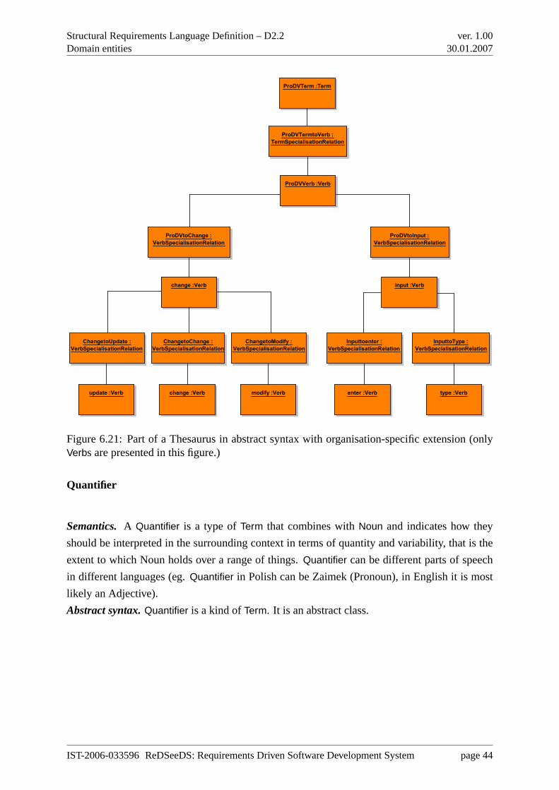
Structural Requirements Language Definition – D2.2Domain entities
ver. 1.0030.01.2007
ProDVVerb :Verb
change :Verb
update :Verb change :Verb modify :Verb
input :Verb
enter :Verb type :Verb
ProDVtoChange :
VerbSpecialisationRelation
ProDVtoInput :
VerbSpecialisationRelation
ChangetoUpdate :
VerbSpecialisationRelation
ChangetoChange :
VerbSpecialisationRelation
ChangetoModify :
VerbSpecialisationRelation
Inputtoenter :
VerbSpecialisationRelation
InputtoType :
VerbSpecialisationRelation
ProDVTerm :Term
ProDVTermtoVerb :
TermSpecialisationRelation
Figure 6.21: Part of a Thesaurus in abstract syntax with organisation-specific extension (onlyVerbs are presented in this figure.)
Quantifier
Semantics.A Quantifier is a type ofTerm that combines withNoun and indicates how they
should be interpreted in the surrounding context in terms of quantity and variability, that is the
extent to which Noun holds over a range of things.Quantifier can be different parts of speech
in different languages (eg.Quantifier in Polish can be Zaimek (Pronoun), in English it is most
likely an Adjective).
Abstract syntax.Quantifier is a kind ofTerm. It is an abstract class.
IST-2006-033596 ReDSeeDS: Requirements Driven Software Development System page 44
Structural Requirements Language Definition – D2.2Domain entities
ver. 1.0030.01.2007
Noun
Semantics.A Noun is a type ofTerm that names objects (a person, place, thing, quality, action
or data).
Abstract syntax.Noun is a kind ofTerm.
Preposition
Semantics.A Preposition is a type ofTerm that combines withPhrases :: Phrases and indicates
how they should be interpreted in the surrounding context.
Abstract syntax.Preposition is a kind ofTerm.
Verb
Semantics.A Verb is a type of aTerm that expresses action or state of being.
Abstract syntax.Verb is a kind of aTerm.
TermSpecialisationRelation
Semantics.TermSpecialisationRelation is an abstract class that defines semantics for all other
relation classes in this package other thanHasHomonym andHasSynonym. TermSpecialisa-
tionRelation inherits concrete syntax formDirectRelationship. The subclasses ofTermSpe-
cialisationRelation are: CondConjunctionSpecialisationRelation, ModalVerbSpecialisationRela-
tion, NounSpecialisationRelation, ModifierSpecialisationRelation, QuantifierSpecialisationRela-
tion, PrepositionSpecialisationRelation. These relations define specific specialisation relations
for the diverse types of terms. Those subclasses ensure that the source and the target of the rela-
tionship are of the same kind ofTerm. The source of each such relationship should be different
from its target -Term cannot be associated with itself.
Abstract syntax. TermSpecialisationRelation is a kind ofDirectRelationship from theUML ::
Kernel package [Obj05b].
IST-2006-033596 ReDSeeDS: Requirements Driven Software Development System page 45
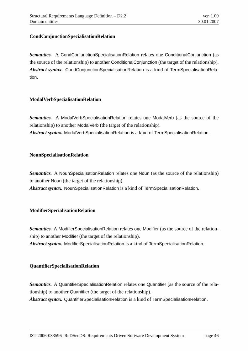
Structural Requirements Language Definition – D2.2Domain entities
ver. 1.0030.01.2007
CondConjunctionSpecialisationRelation
Semantics. A CondConjunctionSpecialisationRelation relates oneConditionalConjunction (as
the source of the relationship) to anotherConditionalConjunction (the target of the relationship).
Abstract syntax.CondConjunctionSpecialisationRelation is a kind ofTermSpecialisationRela-
tion.
ModalVerbSpecialisationRelation
Semantics. A ModalVerbSpecialisationRelation relates oneModalVerb (as the source of the
relationship) to anotherModalVerb (the target of the relationship).
Abstract syntax.ModalVerbSpecialisationRelation is a kind ofTermSpecialisationRelation.
NounSpecialisationRelation
Semantics.A NounSpecialisationRelation relates oneNoun (as the source of the relationship)
to anotherNoun (the target of the relationship).
Abstract syntax.NounSpecialisationRelation is a kind ofTermSpecialisationRelation.
ModifierSpecialisationRelation
Semantics.A ModifierSpecialisationRelation relates oneModifier (as the source of the relation-
ship) to anotherModifier (the target of the relationship).
Abstract syntax.ModifierSpecialisationRelation is a kind ofTermSpecialisationRelation.
QuantifierSpecialisationRelation
Semantics.A QuantifierSpecialisationRelation relates oneQuantifier (as the source of the rela-
tionship) to anotherQuantifier (the target of the relationship).
Abstract syntax.QuantifierSpecialisationRelation is a kind ofTermSpecialisationRelation.
IST-2006-033596 ReDSeeDS: Requirements Driven Software Development System page 46
Structural Requirements Language Definition – D2.2Domain entities
ver. 1.0030.01.2007
PrepositionSpecialisationRelation
Semantics. A PrepositionSpecialisationRelation relates onePreposition (as the source of the
relationship) to anotherPreposition (the target of the relationship).
Abstract syntax.PrepositionSpecialisationRelation is a kind ofTermSpecialisationRelation.
HasHomonym
Semantics.A HasHomonym relates twoTerms that have the same character string as “name”
attribute but that have different meanings.
Abstract syntax.HasHomonym is a kind ofRelationship from UML :: Kernel package [Obj05b].
HasHomonym inherits concrete syntax formRelationship.
HasSynonym
Semantics.A HasSynonym relates twoTerms that have the same meaning but a different char-
acter string as “name” attribute.
Abstract syntax.HasSynonym is a kind ofRelationship from UML :: Kernel package [Obj05b].
HasSynonym inherits concrete syntax formRelationship.
6.7.3 Concrete syntax and examples
Term. It is a string of letters and white spaces having a logical meaning in a specific natural
language.Examples (for English):“car”, “buy”, “look for”, “buy ticket button”, “at”, “must”,
“every”.
Thesaurus.It is a semantic structure that holdsTerms. This structure should allow for semantic-
based reuse of organisation-specificTerms as well as browsing theThesaurus contents by
Phrases :: Phrase names andVerbs associated withPhrases :: Phrases. The concrete syn-
tax is equivalent to the concrete syntax of theDomainVocabulary (compare Figure 6.22 and
Figure 6.3) which is based onKernel :: Package. More important is the tree view presentation
of the Thesaurus as depicted in Figure 6.23. Please note that the tree view depicts only the
specialisation relations. Therefore the thesaurus itself is not shown.
IST-2006-033596 ReDSeeDS: Requirements Driven Software Development System page 47
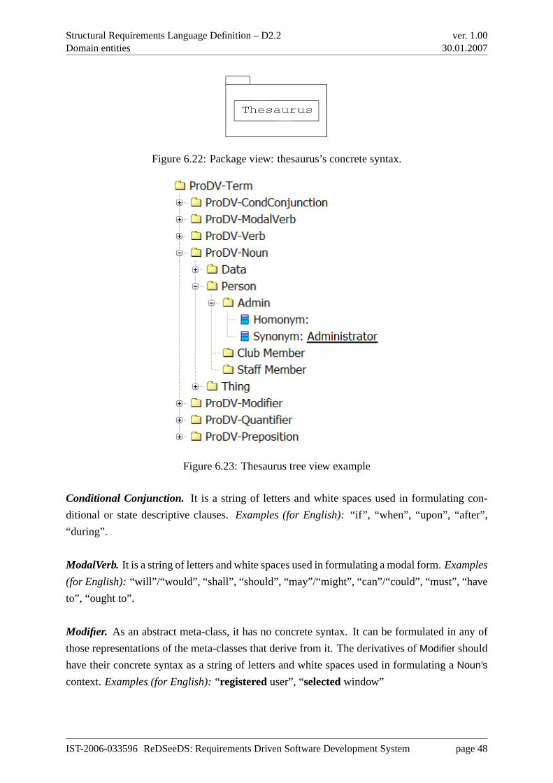
Structural Requirements Language Definition – D2.2Domain entities
ver. 1.0030.01.2007
Figure 6.22: Package view: thesaurus’s concrete syntax.
Figure 6.23: Thesaurus tree view example
Conditional Conjunction. It is a string of letters and white spaces used in formulating con-
ditional or state descriptive clauses.Examples (for English):“if”, “when”, “upon”, “after”,
“during”.
ModalVerb. It is a string of letters and white spaces used in formulating a modal form.Examples
(for English): “will”/“would”, “shall”, “should”, “may”/“might”, “can”/“could”, “must”, “have
to”, “ought to”.
Modifier. As an abstract meta-class, it has no concrete syntax. It can be formulated in any of
those representations of the meta-classes that derive from it. The derivatives ofModifier should
have their concrete syntax as a string of letters and white spaces used in formulating aNoun’s
context.Examples (for English):“ registereduser”, “selectedwindow”
IST-2006-033596 ReDSeeDS: Requirements Driven Software Development System page 48
Structural Requirements Language Definition – D2.2Domain entities
ver. 1.0030.01.2007
Quantifier. As an abstract meta-class, it has no concrete syntax. It can be formulated in any of
those representations of meta-classes that derive from it. The derivatives ofQuantifier should
have their concrete syntax as a string of letters and white spaces used in formulating aNoun’s
context.Examples (for English):“every”, “all”, “no”, “none of”
Noun. It is a string of letters and white spaces used in formulating an objects’ description.
Examples (for English):“user”, “system”, “buy ticket button”, “accessibility”, “saving”
Preposition. It is a string of letters and white spaces used in formulatingPhrases :: Phrases’
context. Examples (for English):“on”, “of”, “to”, “for”, “inside”, “next to”, “in accordance
with”
Verb is a string of letters and white spaces used in formulating an action description.Examples
(for English): “add”, “show”, “save”, “start”, “provide”, “look for”, “choose between”
TermSpecialisationRelation.This relationship between twoTerms is depicted as a package
with a subpackage in the tree view of the thesaurus (see Figure 6.23). Homonyms and Syn-
onyms are presented for each term (see Figure 6.23).
IST-2006-033596 ReDSeeDS: Requirements Driven Software Development System page 49
Structural Requirements Language Definition – D2.2Conclusion
ver. 1.0030.01.2007
Chapter 7
Conclusion
This deliverable presents a novel requirements specification language, more precisely its struc-
tural part. This language is special because of its explicit inclusion of objects existing in the
domain (environment) of the software system to be built —domain objects. While the represen-
tation of a Domain Model (to-be) makes use of standard UML, which is still allowed, additional
descriptions are possible in a newly defined representation of vocabulary. This facilitates a bet-
ter understanding of the requirements per se. Our language is the first requirements specification
language intimately integrated with UML and defined using the same meta-modelling approach
as used for UML itself (using MOF). This deliverable also presents and explains the structural
part of this language definition, from abstract down to concrete syntax.
IST-2006-033596 ReDSeeDS: Requirements Driven Software Development System page 50
Structural Requirements Language Definition – D2.2Bibliography
ver. 1.0030.01.2007
Bibliography
[Dou99] Bruce Powel Douglass.Doing hard time: developing real-time systems with UML,
objects, frameworks, and patterns. Addison-Wesley Longman Publishing Co.,
Inc., Boston, MA, USA, 1999.
[EK02] Gerald Ebner and Hermann Kaindl. Tracing all around in reengineering.IEEE
Software, 19(3):70–77, 2002.
[FHK+05] Norbert E. Fuchs, Stefan Höfler, Kaarel Kaljurand, Fabio Rinaldi, and Gerold
Schneider. Attempto controlled english: A knowledge representation language
readable by humans and machines.Lecture Notes in Computer Science, 3564,
2005.
[Gom01] Hassan Gomaa. Designing concurrent, distributed, and real-time applications with
UML. In ICSE ’01: Proceedings of the 23rd International Conference on Soft-
ware Engineering, pages 737–738, Washington, DC, USA, 2001. IEEE Computer
Society.
[Hoe04] Stefan Hoefler. The syntax of attempto controlled english: An abstract grammar
for ace 4.0, technical report. Technical Report ifi-2004.03, Department of Infor-
matics, University of Zurich, 2004.
[Kai97] H. Kaindl. A practical approach to combining requirements definition and object-
oriented analysis.Annals of Software Engineering, 3:319–343, 1997.
[Kai99] H. Kaindl. Difficulties in the transition from OO analysis to design.IEEE Software,
16(5):94–102, Sept./Oct. 1999.
[Lar01] Craig Larman.Applying UML and Patterns: An Introduction to Object-Oriented
Analysis and Design and the Unified Process. Prentice Hall, Englewood Cliffs,
NJ, second edition, 2001.
[Obj03] Object Management Group.Meta Object Facility (MOF) 2.0 Core Specification,
Final Adopted Specification, ptc/03-10-04, 2003.
IST-2006-033596 ReDSeeDS: Requirements Driven Software Development System page 51
Structural Requirements Language Definition – D2.2Bibliography
ver. 1.0030.01.2007
[Obj05a] Object Management Group.Unified Modeling Language: Infrastructure, version
2.0, formal/05-07-05, 2005.
[Obj05b] Object Management Group.Unified Modeling Language: Superstructure, version
2.0, formal/05-07-04, 2005.
[Obj06] Object Management Group.Meta Object Facility Core Specification, version 2.0,
formal/2006-01-01, 2006.
[SBNS05a] Michał Smiałek, Jacek Bojarski, Wiktor Nowakowski, and Tomasz Straszak. Sce-
nario construction tool based on extended UML metamodel.Lecture Notes in
Computer Science, 3713:414–429, 2005.
[SBNS05b] Michał Smiałek, Jacek Bojarski, Wiktor Nowakowski, and Tomasz Straszak. Writ-
ing coherent user stories with tool support.Lecture Notes in Computer Science,
3556:247–250, 2005.
IST-2006-033596 ReDSeeDS: Requirements Driven Software Development System page 52