Embed Size (px)
Citation preview
Lynde and Harry Bradley School of Technology & Trade Milwaukee, WI ____________________________________________________________________________________
____________________________________________________________________________________
Structural System ________________________________________________________________________________________________________________________________________________________________________
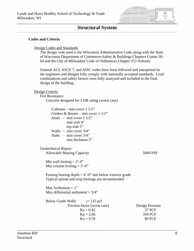
Codes and Criteria
Design Codes and Standards
The design code used is the Wisconsin Administrative Code along with the State of Wisconsin Department of Commerce-Safety & Buildings Chapters Comm 50-64 and the City of Milwaukee Code of Ordinances Chapter 257-Schools. General ACI, ASCE 7, and AISC codes have been followed and interpreted by the engineers and designs fully comply with nationally accepted standards. Load combinations and safety factors were fully analyzed and included in the final design of the building.
Design Criteria
Fire Resistance Concrete designed for 2 HR rating (worst case)
Columns – min cover 1 1/2” Girders & Beams – min cover 1 1/2” Joists – min cover 1 1/2” min web 4” top slab 5” Walls – min cover 3/4” Slabs – min cover 3/4” min thickness 5”
Geotechnical Report Allowable Bearing Capacity 5000 PSF Min wall footing = 2’-0” Min column footing = 3’-0” Footing bearing depth = 4’-0” min below exterior grade Typical spread and strip footings are recommended Max Settlement = 1” Max differential settlement = 3/4” Below Grade Walls: γ= 135 pcf
Friction factor (worst case) Design Pressure Ka = 0.42 57 PCF Kp = 2.66 359 PCF Ko = 0.59 80 PCF
Jonathan Hill 8 Structural
Lynde and Harry Bradley School of Technology & Trade Milwaukee, WI ____________________________________________________________________________________
____________________________________________________________________________________
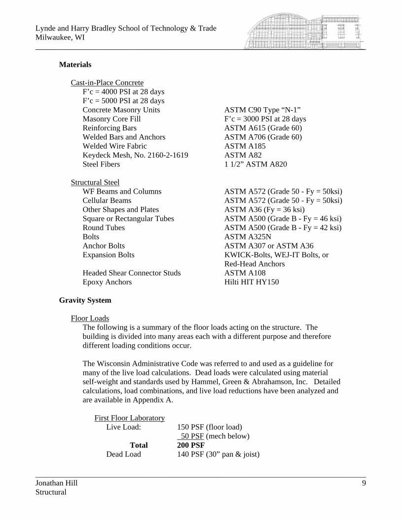
Materials
Cast-in-Place Concrete
F’c = 4000 PSI at 28 days F’c = 5000 PSI at 28 days Concrete Masonry Units ASTM C90 Type “N-1” Masonry Core Fill F’c = 3000 PSI at 28 days Reinforcing Bars ASTM A615 (Grade 60) Welded Bars and Anchors ASTM A706 (Grade 60) Welded Wire Fabric ASTM A185 Keydeck Mesh, No. 2160-2-1619 ASTM A82 Steel Fibers 1 1/2” ASTM A820
Structural Steel
WF Beams and Columns ASTM A572 (Grade 50 - Fy = 50ksi) Cellular Beams ASTM A572 (Grade 50 - Fy = 50ksi) Other Shapes and Plates ASTM A36 (Fy = 36 ksi) Square or Rectangular Tubes ASTM A500 (Grade B - Fy = 46 ksi) Round Tubes ASTM A500 (Grade B - Fy = 42 ksi) Bolts ASTM A325N Anchor Bolts ASTM A307 or ASTM A36 Expansion Bolts KWICK-Bolts, WEJ-IT Bolts, or
Red-Head Anchors Headed Shear Connector Studs ASTM A108 Epoxy Anchors Hilti HIT HY150
Gravity System
Floor Loads The following is a summary of the floor loads acting on the structure. The building is divided into many areas each with a different purpose and therefore different loading conditions occur. The Wisconsin Administrative Code was referred to and used as a guideline for many of the live load calculations. Dead loads were calculated using material self-weight and standards used by Hammel, Green & Abrahamson, Inc. Detailed calculations, load combinations, and live load reductions have been analyzed and are available in Appendix A.
First Floor Laboratory
Live Load: 150 PSF (floor load) 50 PSF (mech below) Total 200 PSF Dead Load 140 PSF (30” pan & joist)
Jonathan Hill 9 Structural
Lynde and Harry Bradley School of Technology & Trade Milwaukee, WI ____________________________________________________________________________________
____________________________________________________________________________________
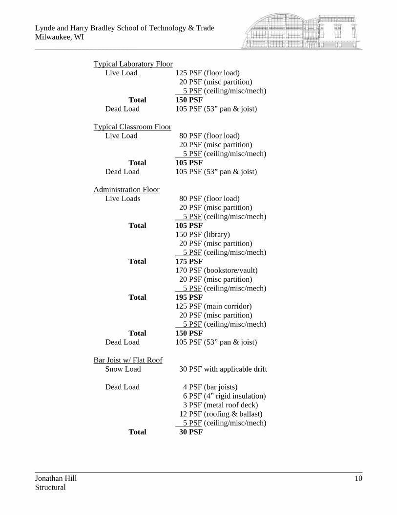
Typical Laboratory Floor
Live Load 125 PSF (floor load) 20 PSF (misc partition) 5 PSF (ceiling/misc/mech) Total 150 PSF Dead Load 105 PSF (53” pan & joist)
Typical Classroom Floor
Live Load 80 PSF (floor load) 20 PSF (misc partition) 5 PSF (ceiling/misc/mech) Total 105 PSF Dead Load 105 PSF (53” pan & joist)
Administration Floor
Live Loads 80 PSF (floor load) 20 PSF (misc partition) 5 PSF (ceiling/misc/mech) Total 105 PSF
150 PSF (library) 20 PSF (misc partition) 5 PSF (ceiling/misc/mech) Total 175 PSF 170 PSF (bookstore/vault) 20 PSF (misc partition) 5 PSF (ceiling/misc/mech) Total 195 PSF
125 PSF (main corridor) 20 PSF (misc partition) 5 PSF (ceiling/misc/mech) Total 150 PSF Dead Load 105 PSF (53” pan & joist)
Bar Joist w/ Flat Roof
Snow Load 30 PSF with applicable drift Dead Load 4 PSF (bar joists) 6 PSF (4” rigid insulation) 3 PSF (metal roof deck) 12 PSF (roofing & ballast) 5 PSF (ceiling/misc/mech) Total 30 PSF
Jonathan Hill 10 Structural
Lynde and Harry Bradley School of Technology & Trade Milwaukee, WI ____________________________________________________________________________________
____________________________________________________________________________________
Curved Roof over Laboratories
Snow Load 30 PSF with applicable drift Dead Load 8 PSF (beams & girders) 3 PSF (metal roof deck) 8 PSF (roofing & insulation) 6 PSF (ceiling/misc/mech) Total 25 PSF
Wall Loads
All wall loads are taken as industry or company standards and reflect the self-weight of the material and or systems.
Interior Partitions
20 PSF (min)
Exterior CMU w/ Brick Veneer 4” Brick 50 PSF 8” CMU 50 PSF Total 100 PSF
Curtainwall / Metal Panel System
20 PSF
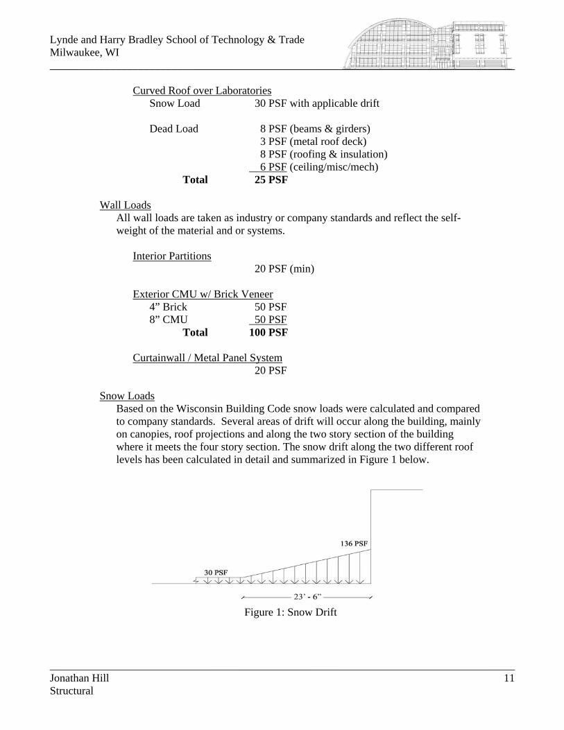
Snow Loads Based on the Wisconsin Building Code snow loads were calculated and compared to company standards. Several areas of drift will occur along the building, mainly on canopies, roof projections and along the two story section of the building where it meets the four story section. The snow drift along the two different roof levels has been calculated in detail and summarized in Figure 1 below.
Figure 1: Snow Drift
Jonathan Hill 11 Structural
Lynde and Harry Bradley School of Technology & Trade Milwaukee, WI ____________________________________________________________________________________
____________________________________________________________________________________
Cast-in-Place Pan and Joist System
The majority of the building is designed using a cast-in-place concrete pan and joist system. Due to the need of a large floor-to-floor height and the possibility of exposed structure, the concrete system was the best choice for the main structural system. The code used for reinforced concrete design and construction was ACI 318-89.
Foundation
The foundation system consists of a combination of stepped, continuous and spread footings. The basement foundation, which occurs only in Area C, resembles the on-grade foundation only differing with the height of its load-bearing walls. Footings have been designed for a maximum soil bearing pressure of 5000 PSF. Continuous footings typically have thicknesses between 2’-0” and 2’-6” and foundation walls are typically 1’-4” thick and centered on the footings.
Columns
Concrete columns carry most of the building load, with only a few scattered steel pieces to support the flat roof and canopies. They are supported by spread footings and are evenly distributed throughout the floors. Column sizes range from 16 to 24 inch squares.
Framing
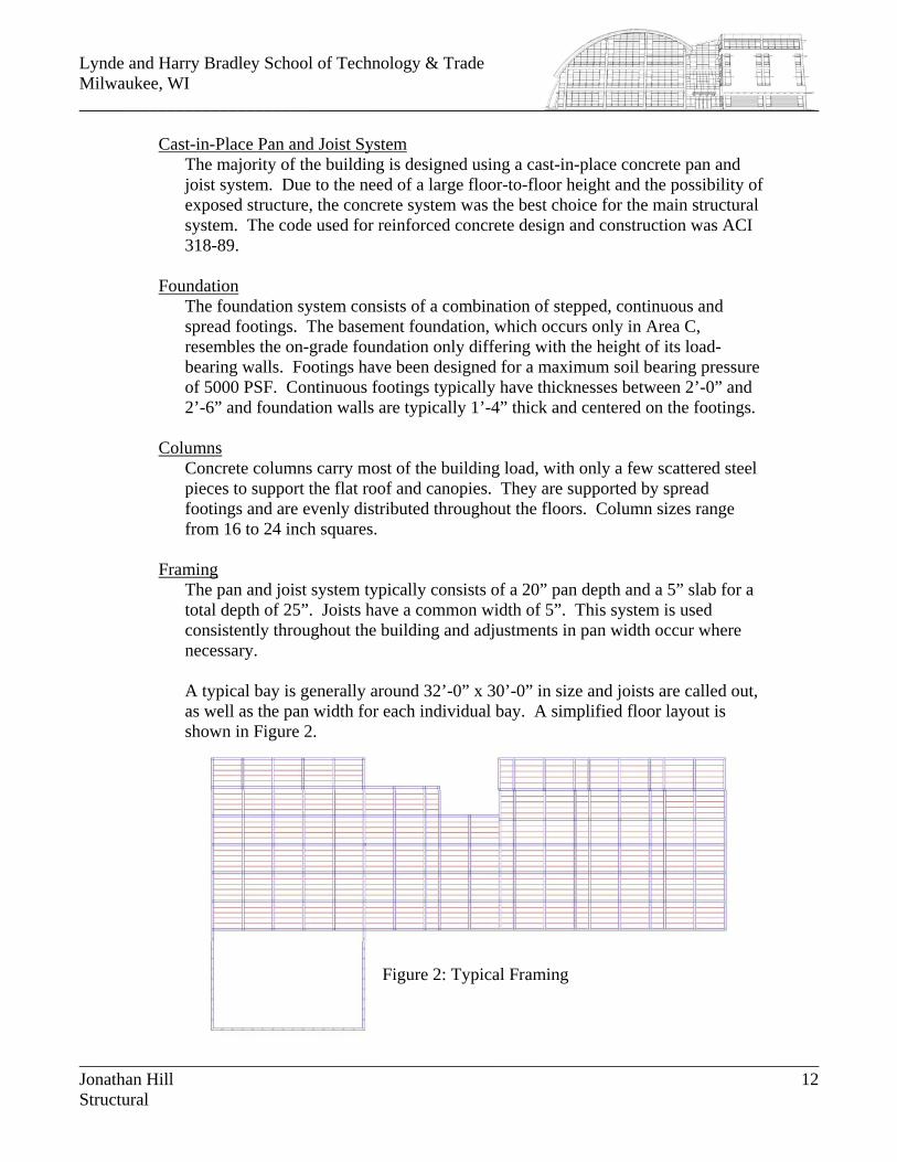
The pan and joist system typically consists of a 20” pan depth and a 5” slab for a total depth of 25”. Joists have a common width of 5”. This system is used consistently throughout the building and adjustments in pan width occur where necessary. A typical bay is generally around 32’-0” x 30’-0” in size and joists are called out, as well as the pan width for each individual bay. A simplified floor layout is shown in Figure 2.
Figure 2: Typical Framing
Jonathan Hill 12 Structural
Lynde and Harry Bradley School of Technology & Trade Milwaukee, WI ____________________________________________________________________________________
____________________________________________________________________________________
Roof System
With the majority of the building loads being taken by the concrete system, steel was used for specialized cases. These cases include elaborate canopies, a standard steel joist supported roof, and a long-spanning barrel roof, which is what makes this building so unique. The designs of these steel systems follow the latest AISC manual and specifications.
Canopies
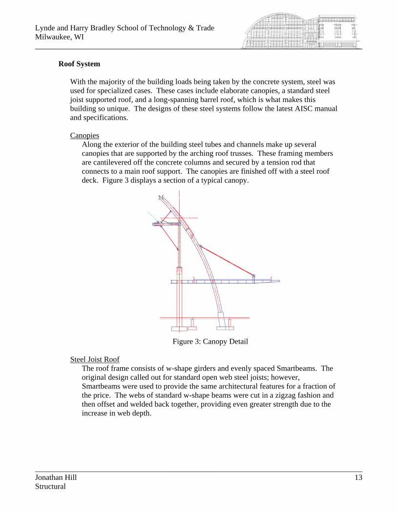
Along the exterior of the building steel tubes and channels make up several canopies that are supported by the arching roof trusses. These framing members are cantilevered off the concrete columns and secured by a tension rod that connects to a main roof support. The canopies are finished off with a steel roof deck. Figure 3 displays a section of a typical canopy.
Figure 3: Canopy Detail
Steel Joist Roof The roof frame consists of w-shape girders and evenly spaced Smartbeams. The original design called out for standard open web steel joists; however, Smartbeams were used to provide the same architectural features for a fraction of the price. The webs of standard w-shape beams were cut in a zigzag fashion and then offset and welded back together, providing even greater strength due to the increase in web depth.
Jonathan Hill 13 Structural
Lynde and Harry Bradley School of Technology & Trade Milwaukee, WI ____________________________________________________________________________________
____________________________________________________________________________________
Barrel Vault Roof
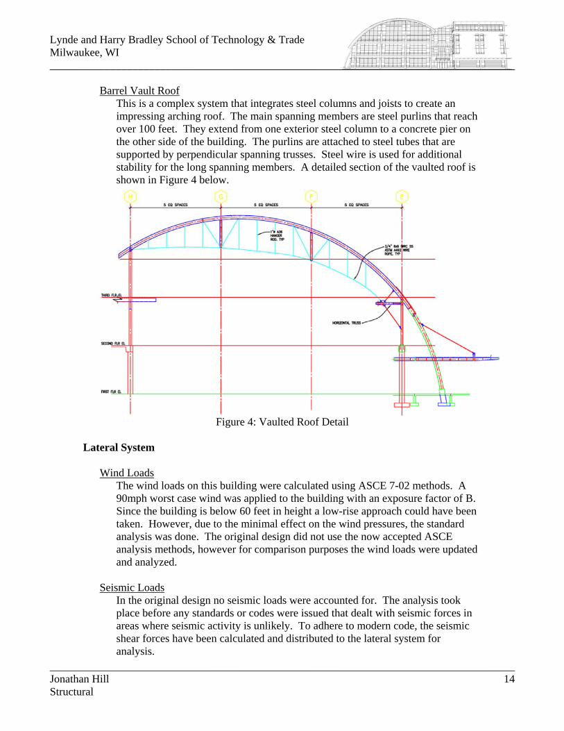
This is a complex system that integrates steel columns and joists to create an impressing arching roof. The main spanning members are steel purlins that reach over 100 feet. They extend from one exterior steel column to a concrete pier on the other side of the building. The purlins are attached to steel tubes that are supported by perpendicular spanning trusses. Steel wire is used for additional stability for the long spanning members. A detailed section of the vaulted roof is shown in Figure 4 below.
Figure 4: Vaulted Roof Detail Lateral System
Wind Loads
The wind loads on this building were calculated using ASCE 7-02 methods. A 90mph worst case wind was applied to the building with an exposure factor of B. Since the building is below 60 feet in height a low-rise approach could have been taken. However, due to the minimal effect on the wind pressures, the standard analysis was done. The original design did not use the now accepted ASCE analysis methods, however for comparison purposes the wind loads were updated and analyzed.
Seismic Loads In the original design no seismic loads were accounted for. The analysis took place before any standards or codes were issued that dealt with seismic forces in areas where seismic activity is unlikely. To adhere to modern code, the seismic shear forces have been calculated and distributed to the lateral system for analysis.
Jonathan Hill 14 Structural
Lynde and Harry Bradley School of Technology & Trade Milwaukee, WI ____________________________________________________________________________________
____________________________________________________________________________________
Lateral Framing System
As mentioned before, the main supporting system of this building is a cast-in-place concrete frame. This being so, nearly all columns and intersecting beams take part in the lateral system and the simply laid out concrete frames carry the loads. However, when analyzing the barrel vault roof, the lateral system becomes a bit more complicated. Steel roof members transfer the lateral loads directly to the concrete beams using a bent plate which is embedded in the beams using expansion bolts. At the other end of the vault roof the steel joists transfer their lateral load into a steel tube column, again using a bent plate, which then distributes the load to its supporting concrete beam. The concrete columns cantilever up to the steel roof joists eliminating any need for moment frames or cross bracing within the steel members; therefore, all steel connections are kept simple and transfer only minimal lateral forces. Once the lateral loads are absorbed by the concrete framing system they are transferred to the foundations. The load path taken in this monolithic system can be seen in the building section below.
Figure 5: Lateral System Section
Jonathan Hill 15 Structural


![Module 4 : Design of Shallow Foundations Lecture 18 ... · Lecture 18 : Structural designs of column and footing [ Section18.3 : Design of Strap Footing ] Objectives In this section](https://img.pdfslide.net/doc/110x75/5e8a8d4d85e38b02b4098db3/module-4-design-of-shallow-foundations-lecture-18-lecture-18-structural.jpg)