Embed Size (px)
Citation preview
SmartLine Technical Information
STT700 SmartLine Temperature Transmitter
Specification
34-TT-03-19, July 2017
Introduction
Part of the SmartLine® family of products, the SmartLine
STT700 is a high performance temperature transmitter
offering high accuracy and stability over a wide range of
process and ambient temperatures. SmartLine easily meets
the most demanding needs for temperature measurement
applications.
Best in Class Features: The STT700 is single or a dual
input temperature transmitter that supports millivolt,
thermocouple and RTD sensors. It is available with either
HART or DE protocol output.
High performance
o Digital accuracy up to 0.15 Deg C for Pt100
o Stability up to ±0.05% of URL per year for ten
years
o 500 mSec update time (single input)
o 1 Sec update time (dual input)
Reliable measurement
o Built in galvanic isolation
o Sensor break detection
o Comprehensive on-board diagnostic capabilities
o Full compliance to SIL 2/3 requirements.
o Available with 4 year warranty
o Supports Namur 89 Wire break
o Direct entry of Callendar-van Dusen coefficients
R0, α, δ and β for calibrated RTD sensors.
Lower Cost of Ownership
o Universal input
o Dual sensor option
o External zero, span, & configuration capability
o Polarity insensitive loop wiring
Figure 1– SmartLine STT700 Temperature
Transmitter (HART) module shown
with dual input capability
Communications/Output Options:
o 4-20 mA DC
o HART ® (version 7.0)
o Honeywell Digitally Enhanced (DE)
All transmitters are available with the above listed
output and communications protocol option.
Mounting Options:
o Direct sensor head mounting in DIN Form A
aluminum housing.
o Other mounting options available include wall,
pipe, DIN Rail or single compartment field housing.
2 STT700 SmartLine Temperature Transmitter
Description Part of the SmartLine® family of products, the SmartLine STT700 is a high performance temperature transmitter offering
high accuracy and stability over a wide range of process and ambient temperatures. The STT700 addresses the broadest
market applications by providing a temperature transmitter that can meet the bulk of the industrial application needs. The
STT700’s versatility, including the ability to select single or dual input, HART or DE protocol, with or without display, various
mounting configurations, and the ability to connect to 2, 3 or 4-wire sensors types, allows your site to standardize on a single
product and thus simplifying support and training.
Configuration Tools
Hand Held Configuration
SmartLine transmitters feature two-way communication and configuration capability between the operator and the transmitter.
This is accomplished via Honeywell’s field-rated Multiple Communication Configuration tool. The Honeywell handheld MC
Toolkit is capable of field configuring HART and DE devices and can also be ordered for use in intrinsically safe environments.
All Honeywell transmitters are designed and tested for compliance with the offered communication protocols and are designed
to operate with any properly validated handheld configuration device.
Personal Computer Configuration
HART Communicator Model 375, 475 or MC Toolkit for HART 7 Models.
Field Device Manager (FDM) Software and FDM Express are also available for managing HART and DE device configurations
(FDC).
Smart Field Communicator (SFC) for DE Models
Diagnostics
SmartLine transmitters all offer digitally accessible diagnostics which aid in providing advanced warning of possible failure
events minimizing unplanned shutdowns, providing lower overall operational costs
System Integration
o All SmartLine products communications protocols meet all of the most current published standards for HART
o SmartLine STT700 is fully compatible with Honeywell’s DE protocol.
STT250 Compatibility
The STT700 design allows it to easily replace an existing STT250 Temperature Transmitter. The STT700 physically will fit into
an existing STT250 mount and the STT700 offers the same functions as a STT250.
STT700 SmartLine Temperature Transmitter 3
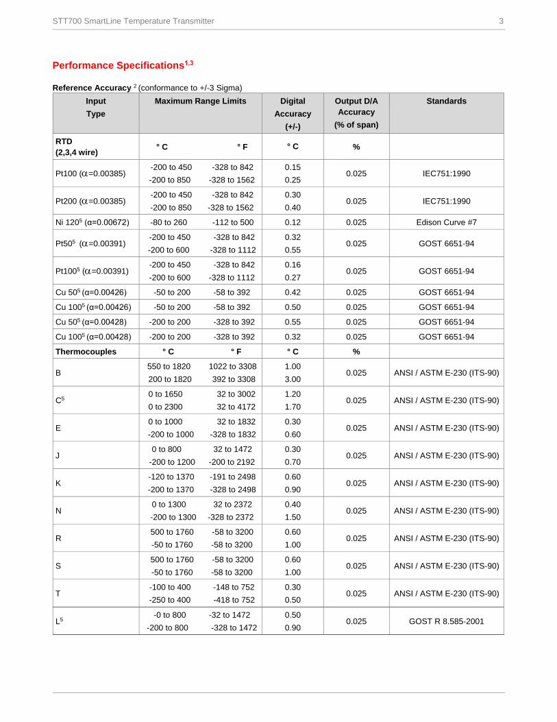
Performance Specifications1,3
Reference Accuracy 2 (conformance to +/-3 Sigma)
Input
Type
Maximum Range Limits Digital
Accuracy
(+/-)
Output D/A
Accuracy
(% of span)
Standards
RTD
(2,3,4 wire) ° C ° F ° C %
Pt100 (=0.00385) -200 to 450 -328 to 842
-200 to 850 -328 to 1562
0.15
0.25 0.025 IEC751:1990
Pt200 (=0.00385) -200 to 450 -328 to 842
-200 to 850 -328 to 1562
0.30
0.40 0.025 IEC751:1990
Ni 1205 (α=0.00672) -80 to 260 -112 to 500 0.12 0.025 Edison Curve #7
Pt505 (=0.00391) -200 to 450 -328 to 842
-200 to 600 -328 to 1112
0.32
0.55 0.025 GOST 6651-94
Pt1005 (=0.00391) -200 to 450 -328 to 842
-200 to 600 -328 to 1112
0.16
0.27 0.025 GOST 6651-94
Cu 505 (α=0.00426) -50 to 200 -58 to 392 0.42 0.025 GOST 6651-94
Cu 1005 (α=0.00426) -50 to 200 -58 to 392 0.50 0.025 GOST 6651-94
Cu 505 (α=0.00428) -200 to 200 -328 to 392 0.55 0.025 GOST 6651-94
Cu 1005 (α=0.00428) -200 to 200 -328 to 392 0.32 0.025 GOST 6651-94
Thermocouples ° C ° F ° C %
B 550 to 1820 1022 to 3308
200 to 1820 392 to 3308
1.00
3.00 0.025 ANSI / ASTM E-230 (ITS-90)
C5 0 to 1650 32 to 3002
0 to 2300 32 to 4172
1.20
1.70 0.025 ANSI / ASTM E-230 (ITS-90)
E 0 to 1000 32 to 1832
-200 to 1000 -328 to 1832
0.30
0.60 0.025 ANSI / ASTM E-230 (ITS-90)
J 0 to 800 32 to 1472
-200 to 1200 -200 to 2192
0.30
0.70 0.025 ANSI / ASTM E-230 (ITS-90)
K -120 to 1370 -191 to 2498
-200 to 1370 -328 to 2498
0.60
0.90 0.025 ANSI / ASTM E-230 (ITS-90)
N 0 to 1300 32 to 2372
-200 to 1300 -328 to 2372
0.40
1.50 0.025 ANSI / ASTM E-230 (ITS-90)
R 500 to 1760 -58 to 3200
-50 to 1760 -58 to 3200
0.60
1.00 0.025 ANSI / ASTM E-230 (ITS-90)
S 500 to 1760 -58 to 3200
-50 to 1760 -58 to 3200
0.60
1.00 0.025 ANSI / ASTM E-230 (ITS-90)
T -100 to 400 -148 to 752
-250 to 400 -418 to 752
0.30
0.50 0.025 ANSI / ASTM E-230 (ITS-90)
L5 -0 to 800 -32 to 1472
-200 to 800 -328 to 1472
0.50
0.90 0.025 GOST R 8.585-2001
4 STT700 Smart Temperature
1. Digital Accuracy is accuracy of the digital value accessed by the Host system and the handheld communicator
2. Total analog accuracy is the sum of digital accuracy and output D/A Accuracy
3. Output D/A Accuracy is applicable to the 4 to 20 mA Signal output
4. For TC inputs, CJ accuracy shall be added to digital accuracy to calculate the total digital accuracy
5. Not available in DE transmitters.
6. Japanese Pt100J (= 0.003916) may be obtained by using the CVD algorithm with Pt100D.
Differential Temperature Measurement SmartLine STT700 Temperature supports differential temperature measurements for dual input transmitters. When the loop current mode is set to "Differential" then the input range is from A to B for sensor 1 & 2 where
A = Sensor 1 Minimum - Sensor 2 Maximum B = Sensor 1 Maximum - Sensor 2 Minimum
Digital Accuracy for differential temperature measurement
If both input types are the same, then the digital accuracy equals 1.5 times the worst case accuracy for that input type.
If the input types are different, then the digital accuracy equals the sum of the worst case sensor 1 and sensor 2 accuracies. For example, assume that input 1 is a J T/C and input 2 is an R T/C. Assume that the desired operating range is between 0 and +400 °C. The digital accuracy for a J T/C in this range is 0.30 °C and the digital accuracy for an R T/C in this range is 1.00 °C. Therefore, the worst case digital accuracy would be 1.30 °C.
Callendar - Van Dusen Algorithm (CVD)
The easy to use Callendar - Van Dusen (CVD) algorithm allows the use of calibrated platinum RTD sensors to increase the
overall system accuracy. Simply enable the algorithm and then enter the four CVD coefficients supplied with the calibrated
RTD sensor into the transmitter. Honeywell can preprogram the CVD constants at the factory when the Custom
Configuration option is selected and the CVD constants are supplied at order entry.
Performance under Rated Conditions – All models Parameter Description
Input Span Adjustment Range No limits to adjustments within the maximum range except minimum span limit of 1
engineering unit
Analog Output
Digital Communications:
Two-wire, 4 to 20 mA
HART 7 protocol compliant
Honeywell Digitally Enhanced (DE) protocol compliant
Output Failure Modes
Honeywell Standard: NAMUR NE 43 Compliance:
Normal Limits: 3.8 – 20.8 mA 3.8 – 20.5 mA
Failure Mode: ≤ 3.6 mA and ≥ 21.5 mA ≤ 3.6 mA and ≥ 21.5 mA
Output Accuracy ±0.025 % span
Supply Voltage Effect 0.005 % span per volt.
Transmitter Turn on Time
(includes power up & test
algorithms)
HART or DE: 6 sec.
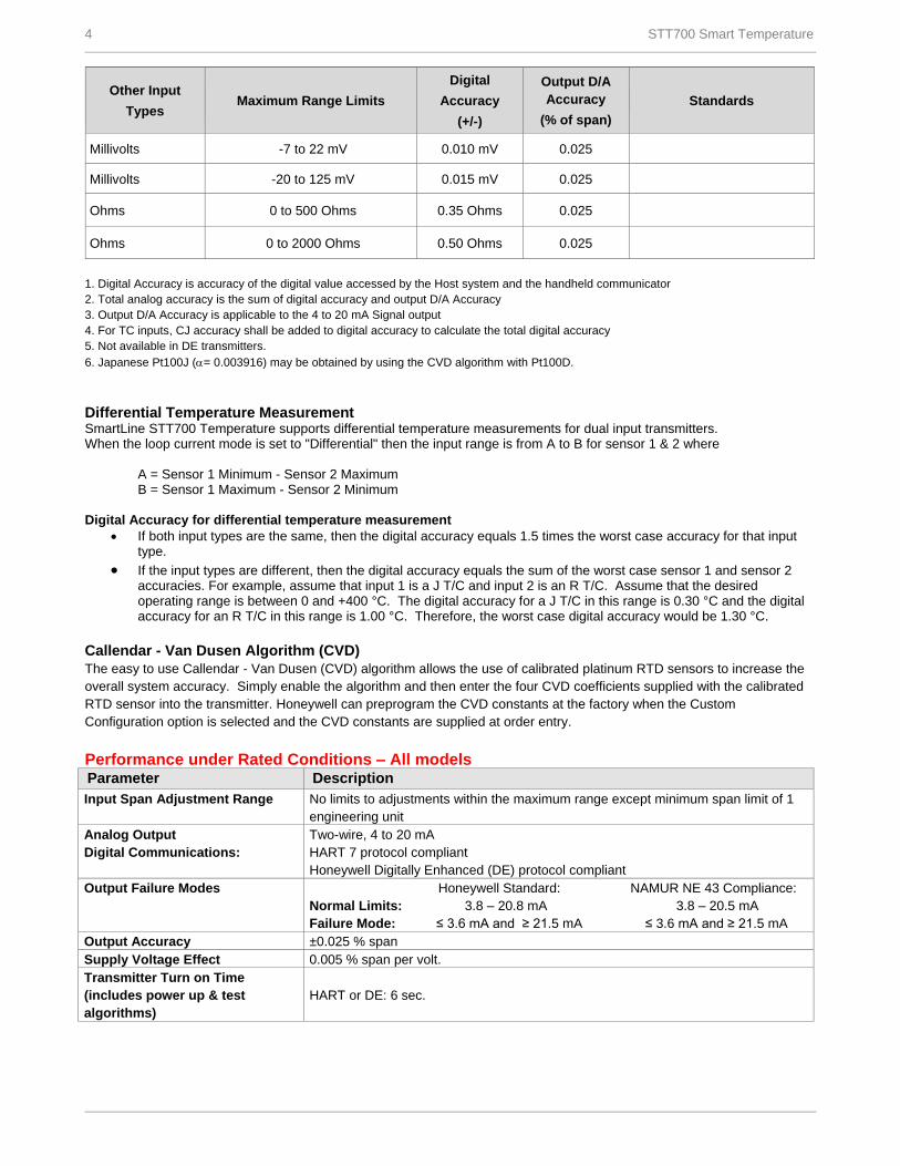
Other Input
Types Maximum Range Limits
Digital
Accuracy
(+/-)
Output D/A
Accuracy
(% of span)
Standards
Millivolts -7 to 22 mV 0.010 mV 0.025
Millivolts -20 to 125 mV 0.015 mV 0.025
Ohms 0 to 500 Ohms 0.35 Ohms 0.025
Ohms 0 to 2000 Ohms 0.50 Ohms 0.025
STT700 Smart Temperature 5
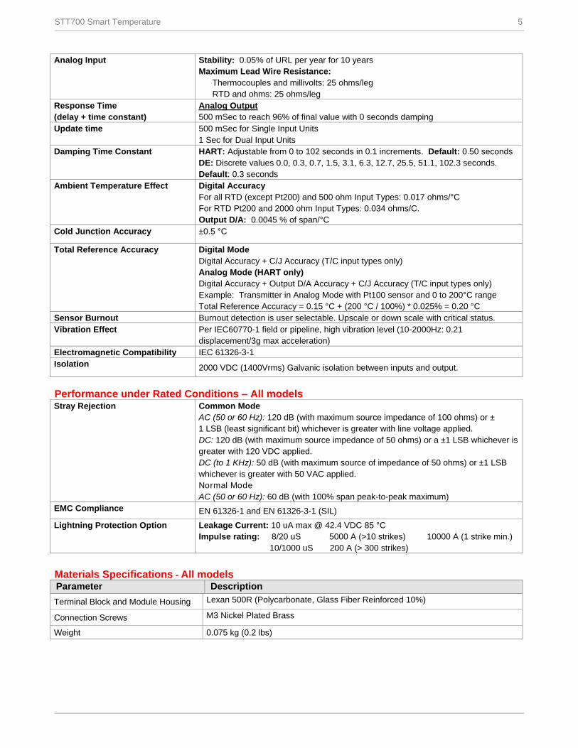
Analog Input
Stability: 0.05% of URL per year for 10 years
Maximum Lead Wire Resistance:
Thermocouples and millivolts: 25 ohms/leg
RTD and ohms: 25 ohms/leg
Response Time
(delay + time constant)
Analog Output
500 mSec to reach 96% of final value with 0 seconds damping
Update time 500 mSec for Single Input Units
1 Sec for Dual Input Units
Damping Time Constant HART: Adjustable from 0 to 102 seconds in 0.1 increments. Default: 0.50 seconds
DE: Discrete values 0.0, 0.3, 0.7, 1.5, 3.1, 6.3, 12.7, 25.5, 51.1, 102.3 seconds.
Default: 0.3 seconds
Ambient Temperature Effect Digital Accuracy
For all RTD (except Pt200) and 500 ohm Input Types: 0.017 ohms/°C For RTD Pt200 and 2000 ohm Input Types: 0.034 ohms/C.
Output D/A: 0.0045 % of span/°C
Cold Junction Accuracy ±0.5 °C
Total Reference Accuracy Digital Mode
Digital Accuracy + C/J Accuracy (T/C input types only)
Analog Mode (HART only)
Digital Accuracy + Output D/A Accuracy + C/J Accuracy (T/C input types only)
Example: Transmitter in Analog Mode with Pt100 sensor and 0 to 200°C range
Total Reference Accuracy = 0.15 °C + (200 °C / 100%) * 0.025% = 0.20 °C
Sensor Burnout Burnout detection is user selectable. Upscale or down scale with critical status.
Vibration Effect
Per IEC60770-1 field or pipeline, high vibration level (10-2000Hz: 0.21
displacement/3g max acceleration)
Electromagnetic Compatibility IEC 61326-3-1
Isolation 2000 VDC (1400Vrms) Galvanic isolation between inputs and output.
Performance under Rated Conditions – All models Stray Rejection Common Mode
AC (50 or 60 Hz): 120 dB (with maximum source impedance of 100 ohms) or ±
1 LSB (least significant bit) whichever is greater with line voltage applied.
DC: 120 dB (with maximum source impedance of 50 ohms) or a ±1 LSB whichever is
greater with 120 VDC applied.
DC (to 1 KHz): 50 dB (with maximum source of impedance of 50 ohms) or ±1 LSB
whichever is greater with 50 VAC applied.
Normal Mode
AC (50 or 60 Hz): 60 dB (with 100% span peak-to-peak maximum)
EMC Compliance EN 61326-1 and EN 61326-3-1 (SIL)
Lightning Protection Option
Leakage Current: 10 uA max @ 42.4 VDC 85 °C
Impulse rating: 8/20 uS 5000 A (>10 strikes) 10000 A (1 strike min.)
10/1000 uS 200 A (> 300 strikes)
Materials Specifications - All models
Parameter Description
Terminal Block and Module Housing Lexan 500R (Polycarbonate, Glass Fiber Reinforced 10%)
Connection Screws M3 Nickel Plated Brass
Weight 0.075 kg (0.2 lbs)
6 STT700 Smart Temperature
Operating Conditions – All models
Parameter Reference
Condition
Rated Condition Operative Limits Transportation and
Storage
C F C F C F C F
Ambient Temperature 25±1 77±2 -40 to 85 -40 to 185 -40 to 85 -40 to 185 -55 to 120 -67 to 248
Humidity %RH 10 to 55 0 to 100 0 to 100 0 to 100
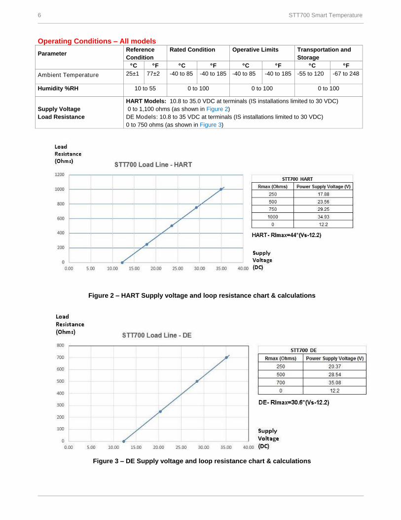
Supply Voltage
Load Resistance
HART Models: 10.8 to 35.0 VDC at terminals (IS installations limited to 30 VDC)
0 to 1,100 ohms (as shown in Figure 2)
DE Models: 10.8 to 35 VDC at terminals (IS installations limited to 30 VDC)
0 to 750 ohms (as shown in Figure 3)
Figure 2 – HART Supply voltage and loop resistance chart & calculations
Figure 3 – DE Supply voltage and loop resistance chart & calculations
STT700 Smart Temperature 7
Physical Mounting and Construction The STT700 Temperature Transmitter is designed to be mounted in a DIN Form A aluminum housing for direct installation
with the temperature sensor or can be provided in a remote pipe or wall mount housing. Details for the available housings
are in document #EN0I-6032. The STT700 temperature transmitter module can also be DIN rail mounted to a top hat or “G”
rail via a clip.
Integral Meters
Honeywell’s Series STT700 temperature transmitters can be supplied with local or remote indication. An Engineering Units
(EU) meter can be mounted integral to the transmitter inside the field mount housing. Order an integral meter as part of the
model number; Table III _ _ _ 1 _ . Order a remote meter as model RMA300. The EU meter displays temperature in
engineering units. DE transmitters can use the EU Meter as long as they are configured to operate in the analog mode.
Refer to document #34-ST-25-08D for more details.
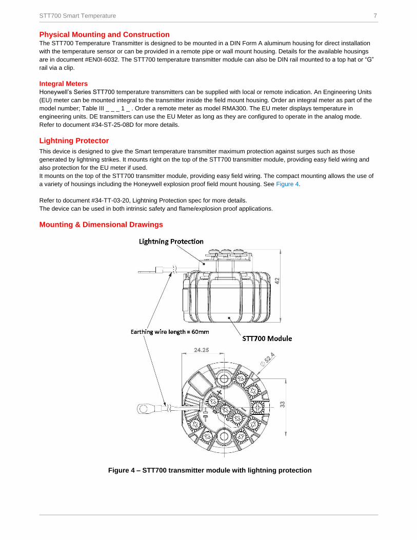
Lightning Protector
This device is designed to give the Smart temperature transmitter maximum protection against surges such as those
generated by lightning strikes. It mounts right on the top of the STT700 transmitter module, providing easy field wiring and
also protection for the EU meter if used.
It mounts on the top of the STT700 transmitter module, providing easy field wiring. The compact mounting allows the use of
a variety of housings including the Honeywell explosion proof field mount housing. See Figure 4.
Refer to document #34-TT-03-20, Lightning Protection spec for more details.
The device can be used in both intrinsic safety and flame/explosion proof applications.
Mounting & Dimensional Drawings
Figure 4 – STT700 transmitter module with lightning protection
8 STT700 Smart Temperature
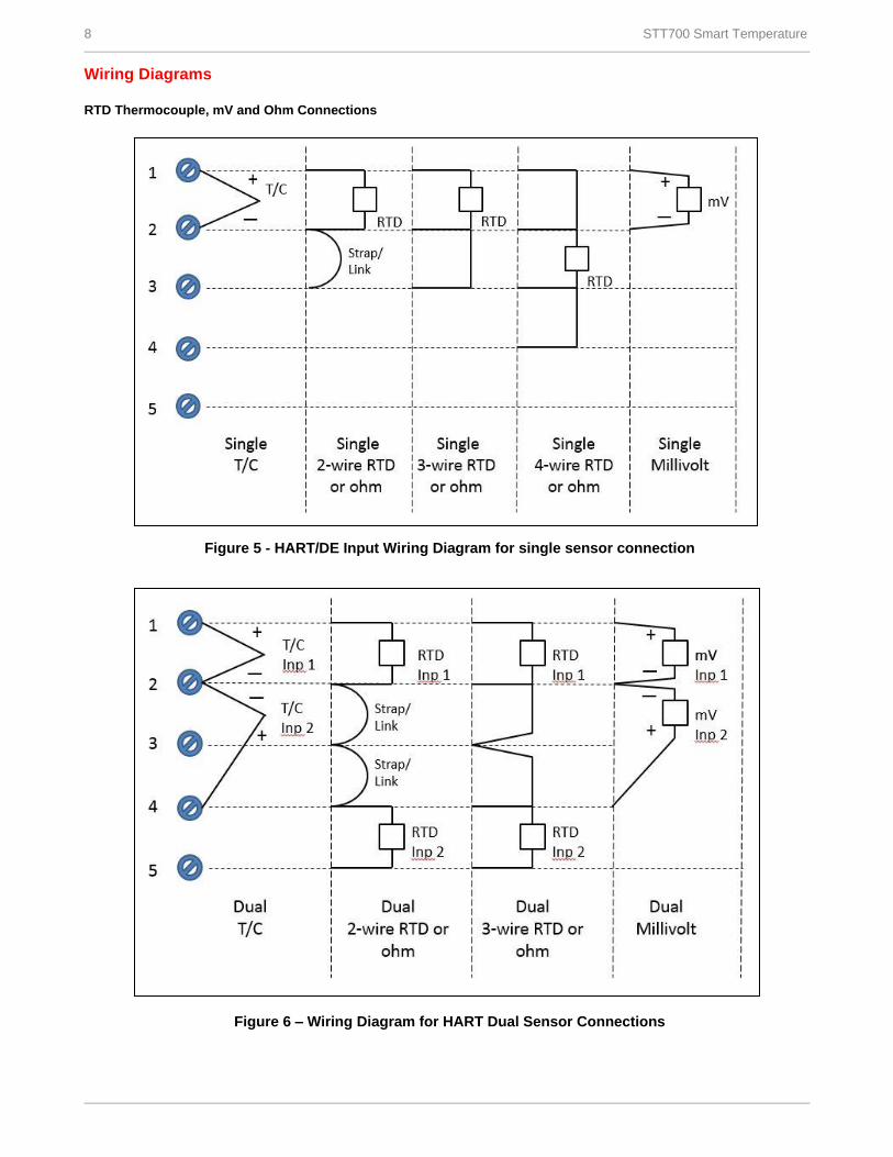
Wiring Diagrams RTD Thermocouple, mV and Ohm Connections
Figure 5 - HART/DE Input Wiring Diagram for single sensor connection
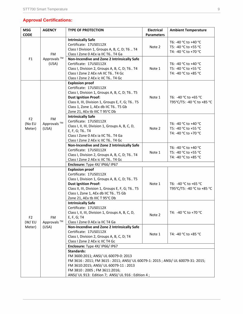
Figure 6 – Wiring Diagram for HART Dual Sensor Connections
STT700 Smart Temperature 9
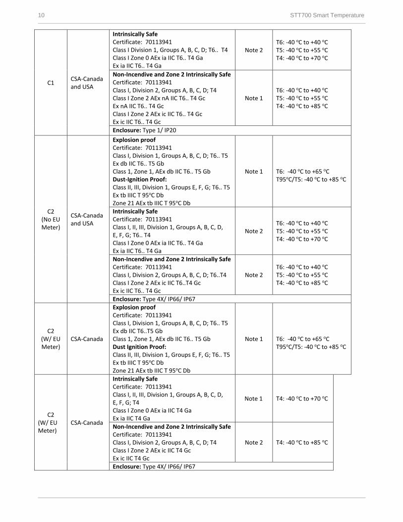
Approval Certifications: MSG CODE
AGENCY TYPE OF PROTECTION Electrical Parameters
Ambient Temperature
F1 FM
Approvals TM (USA)
Intrinsically Safe Certificate: 17US0112X Class I Division 1, Groups A, B, C, D; T6 .. T4 Class I Zone 0 AEx ia IIC T6.. T4 Ga
Note 2 T6: -40 oC to +40 oC T5: -40 oC to +55 oC T4: -40 oC to +70 oC
Non-Incendive and Zone 2 Intrinsically Safe Certificate: 17US0112X Class I, Division 2, Groups A, B, C, D; T6.. T4 Class I Zone 2 AEx nA IIC T6.. T4 Gc Class I Zone 2 AEx ic IIC T6.. T4 Gc
Note 1 T6: -40 oC to +40 oC T5: -40 oC to +55 oC T4: -40 oC to +85 oC
F2 (No EU Meter)
FM Approvals TM (USA)
Explosion proof Certificate: 17US0112X Class I, Division 1, Groups A, B, C, D; T6.. T5 Dust Ignition Proof: Class II, III, Division 1, Groups E, F, G; T6.. T5 Class 1, Zone 1, AEx db IIC T6.. T5 Gb Zone 21, AEx tb IIIC T 95oC Db
Note 1 T6: -40 oC to +65 oC T95oC/T5: -40 oC to +85 oC
Intrinsically Safe Certificate: 17US0112X Class I, II, III, Division 1, Groups A, B, C, D, E, F, G; T6.. T4 Class I Zone 0 AEx ia IIC T6.. T4 Ga Class I Zone 2 AEx ic IIC T6.. T4 Gc
Note 2 T6: -40 oC to +40 oC T5: -40 oC to +55 oC T4: -40 oC to +70 oC
Non-Incendive and Zone 2 Intrinsically Safe Certificate: 17US0112X Class I, Division 2, Groups A, B, C, D; T6.. T4 Class I Zone 2 AEx ic IIC T6.. T4 Gc
Note 1 T6: -40 oC to +40 oC T5: -40 oC to +55 oC T4: -40 oC to +85 oC
Enclosure: Type 4X/ IP66/ IP67
F2 (W/ EU Meter)
FM Approvals TM (USA)
Explosion proof Certificate: 17US0112X Class I, Division 1, Groups A, B, C, D; T6.. T5 Dust Ignition Proof: Class II, III, Division 1, Groups E, F, G; T6.. T5 Class I, Zone 1, AEx db IIC T6.. T5 Gb Zone 21, AEx tb IIIC T 95oC Db
Note 1 T6: -40 oC to +65 oC T95oC/T5: -40 oC to +85 oC
Intrinsically Safe Certificate: 17US0112X Class I, II, III, Division 1, Groups A, B, C, D, E, F, G; T4 Class I Zone 0 AEx ia IIC T4 Ga
Note 2
T4: -40 oC to +70 oC
Non-Incendive and Zone 2 Intrinsically Safe Certificate: 17US0112X Class I, Division 2, Groups A, B, C, D; T4 Class I Zone 2 AEx ic IIC T4 Gc
Note 1 T4: -40 oC to +85 oC
Enclosure: Type 4X/ IP66/ IP67 Standards: FM 3600:2011; ANSI/ UL 60079-0: 2013 FM 3616 : 2011; FM 3615 : 2011; ANSI/ UL 60079-1: 2015 ; ANSI/ UL 60079-31: 2015; FM 3610:2015; ANSI/ UL 60079-11 : 2013 FM 3810 : 2005 ; FM 3611:2016; ANSI/ UL 913: Edition 7; ANSI/ UL 916 : Edition 4 ;
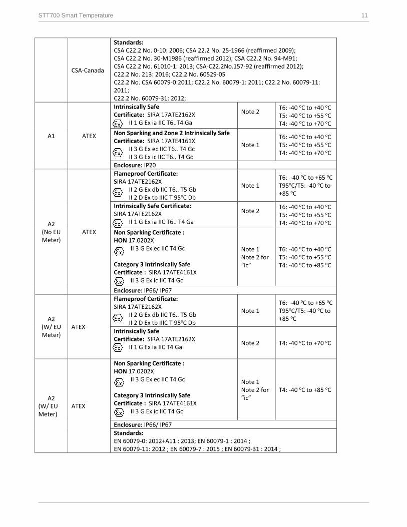
10 STT700 Smart Temperature
C1 CSA-Canada and USA
Intrinsically Safe Certificate: 70113941 Class I Division 1, Groups A, B, C, D; T6.. T4 Class I Zone 0 AEx ia IIC T6.. T4 Ga Ex ia IIC T6.. T4 Ga
Note 2 T6: -40 oC to +40 oC T5: -40 oC to +55 oC T4: -40 oC to +70 oC
Non-Incendive and Zone 2 Intrinsically Safe Certificate: 70113941 Class I, Division 2, Groups A, B, C, D; T4 Class I Zone 2 AEx nA IIC T6.. T4 Gc Ex nA IIC T6.. T4 Gc Class I Zone 2 AEx ic IIC T6.. T4 Gc Ex ic IIC T6.. T4 Gc
Note 1 T6: -40 oC to +40 oC T5: -40 oC to +55 oC T4: -40 oC to +85 oC
Enclosure: Type 1/ IP20
C2 (No EU Meter)
CSA-Canada and USA
Explosion proof Certificate: 70113941 Class I, Division 1, Groups A, B, C, D; T6.. T5 Ex db IIC T6.. T5 Gb Class 1, Zone 1, AEx db IIC T6.. T5 Gb Dust-Ignition Proof: Class II, III, Division 1, Groups E, F, G; T6.. T5 Ex tb IIIC T 95oC Db Zone 21 AEx tb IIIC T 95oC Db
Note 1 T6: -40 oC to +65 oC T95oC/T5: -40 oC to +85 oC
Intrinsically Safe Certificate: 70113941 Class I, II, III, Division 1, Groups A, B, C, D, E, F, G; T6.. T4 Class I Zone 0 AEx ia IIC T6.. T4 Ga Ex ia IIC T6.. T4 Ga
Note 2 T6: -40 oC to +40 oC T5: -40 oC to +55 oC T4: -40 oC to +70 oC
Non-Incendive and Zone 2 Intrinsically Safe Certificate: 70113941 Class I, Division 2, Groups A, B, C, D; T6..T4 Class I Zone 2 AEx ic IIC T6..T4 Gc Ex ic IIC T6.. T4 Gc
Note 2 T6: -40 oC to +40 oC T5: -40 oC to +55 oC T4: -40 oC to +85 oC
Enclosure: Type 4X/ IP66/ IP67
C2 (W/ EU Meter)
CSA-Canada
Explosion proof Certificate: 70113941 Class I, Division 1, Groups A, B, C, D; T6.. T5 Ex db IIC T6..T5 Gb Class 1, Zone 1, AEx db IIC T6.. T5 Gb Dust Ignition Proof: Class II, III, Division 1, Groups E, F, G; T6.. T5 Ex tb IIIC T 95oC Db Zone 21 AEx tb IIIC T 95oC Db
Note 1 T6: -40 oC to +65 oC T95oC/T5: -40 oC to +85 oC
C2 (W/ EU Meter)
CSA-Canada
Intrinsically Safe Certificate: 70113941 Class I, II, III, Division 1, Groups A, B, C, D, E, F, G; T4 Class I Zone 0 AEx ia IIC T4 Ga Ex ia IIC T4 Ga
Note 1 T4: -40 oC to +70 oC
Non-Incendive and Zone 2 Intrinsically Safe Certificate: 70113941 Class I, Division 2, Groups A, B, C, D; T4 Class I Zone 2 AEx ic IIC T4 Gc Ex ic IIC T4 Gc
Note 2 T4: -40 oC to +85 oC
Enclosure: Type 4X/ IP66/ IP67
STT700 Smart Temperature 11
CSA-Canada
Standards: CSA C22.2 No. 0-10: 2006; CSA 22.2 No. 25-1966 (reaffirmed 2009); CSA C22.2 No. 30-M1986 (reaffirmed 2012); CSA C22.2 No. 94-M91; CSA C22.2 No. 61010-1: 2013; CSA-C22.2No.157-92 (reaffirmed 2012); C22.2 No. 213: 2016; C22.2 No. 60529-05 C22.2 No. CSA 60079-0:2011; C22.2 No. 60079-1: 2011; C22.2 No. 60079-11: 2011; C22.2 No. 60079-31: 2012;
A1 ATEX
Intrinsically Safe Certificate: SIRA 17ATE2162X
II 1 G Ex ia IIC T6..T4 Ga
Note 2
T6: -40 oC to +40 oC T5: -40 oC to +55 oC T4: -40 oC to +70 oC
Non Sparking and Zone 2 Intrinsically Safe Certificate: SIRA 17ATE4161X
II 3 G Ex ec IIC T6.. T4 Gc II 3 G Ex ic IIC T6.. T4 Gc
Note 1 T6: -40 oC to +40 oC T5: -40 oC to +55 oC T4: -40 oC to +70 oC
Enclosure: IP20
A2 (No EU Meter)
ATEX
Flameproof Certificate: SIRA 17ATE2162X
II 2 G Ex db IIC T6.. T5 Gb II 2 D Ex tb IIIC T 95oC Db
Note 1 T6: -40 oC to +65 oC T95oC/T5: -40 oC to +85 oC
Intrinsically Safe Certificate: SIRA 17ATE2162X
II 1 G Ex ia IIC T6.. T4 Ga
Note 2
T6: -40 oC to +40 oC T5: -40 oC to +55 oC T4: -40 oC to +70 oC
Non Sparking Certificate : HON 17.0202X
II 3 G Ex ec IIC T4 Gc
Category 3 Intrinsically Safe Certificate : SIRA 17ATE4161X
II 3 G Ex ic IIC T4 Gc
Note 1 Note 2 for “ic”
T6: -40 oC to +40 oC T5: -40 oC to +55 oC T4: -40 oC to +85 oC
Enclosure: IP66/ IP67
A2 (W/ EU Meter)
ATEX
Flameproof Certificate: SIRA 17ATE2162X
II 2 G Ex db IIC T6.. T5 Gb II 2 D Ex tb IIIC T 95oC Db
Note 1 T6: -40 oC to +65 oC T95oC/T5: -40 oC to +85 oC
Intrinsically Safe Certificate: SIRA 17ATE2162X
II 1 G Ex ia IIC T4 Ga
Note 2 T4: -40 oC to +70 oC
A2 (W/ EU Meter)
ATEX
Non Sparking Certificate : HON 17.0202X
II 3 G Ex ec IIC T4 Gc
Category 3 Intrinsically Safe Certificate : SIRA 17ATE4161X
II 3 G Ex ic IIC T4 Gc
Note 1 Note 2 for “ic”
T4: -40 oC to +85 oC
Enclosure: IP66/ IP67 Standards: EN 60079-0: 2012+A11 : 2013; EN 60079-1 : 2014 ; EN 60079-11: 2012 ; EN 60079-7 : 2015 ; EN 60079-31 : 2014 ;
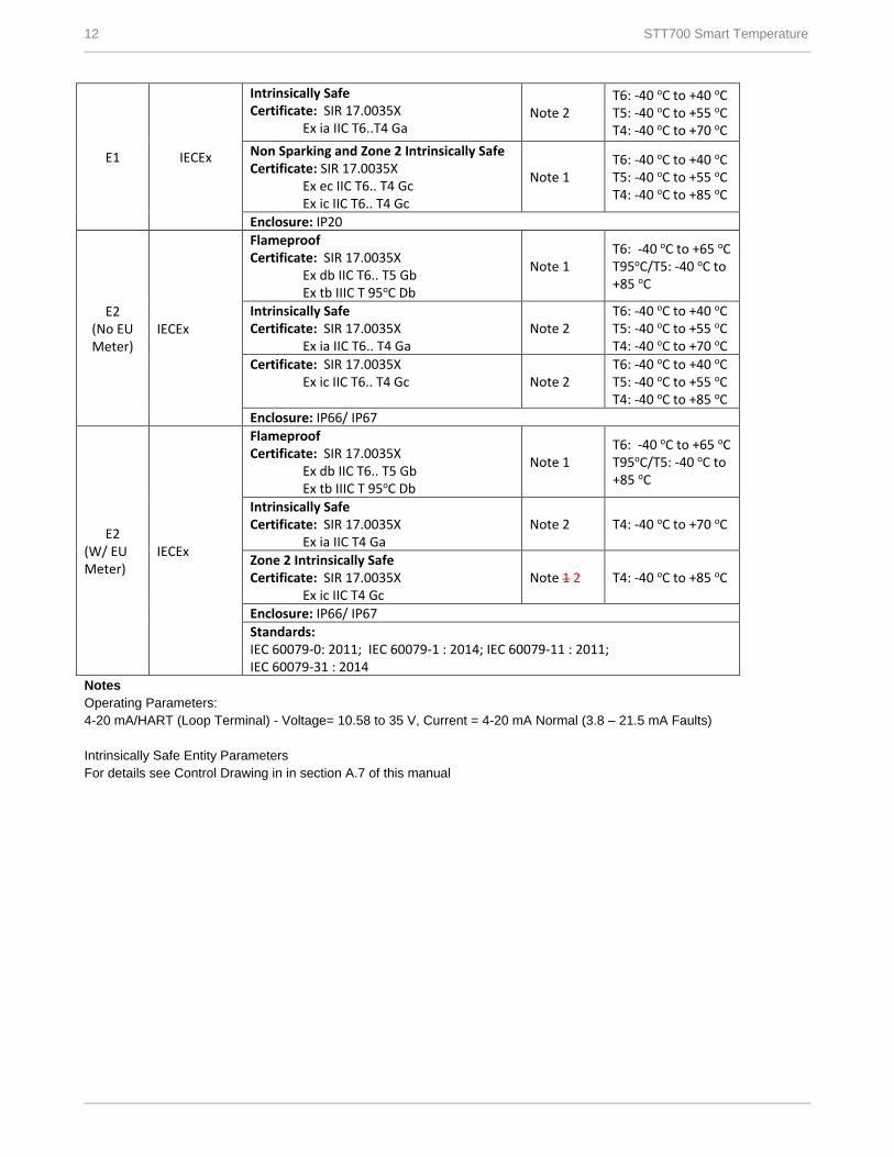
12 STT700 Smart Temperature
E1 IECEx
Intrinsically Safe Certificate: SIR 17.0035X
Ex ia IIC T6..T4 Ga Note 2
T6: -40 oC to +40 oC T5: -40 oC to +55 oC T4: -40 oC to +70 oC
Non Sparking and Zone 2 Intrinsically Safe Certificate: SIR 17.0035X
Ex ec IIC T6.. T4 Gc Ex ic IIC T6.. T4 Gc
Note 1 T6: -40 oC to +40 oC T5: -40 oC to +55 oC T4: -40 oC to +85 oC
Enclosure: IP20
E2 (No EU Meter)
IECEx
Flameproof Certificate: SIR 17.0035X
Ex db IIC T6.. T5 Gb Ex tb IIIC T 95oC Db
Note 1 T6: -40 oC to +65 oC T95oC/T5: -40 oC to +85 oC
Intrinsically Safe Certificate: SIR 17.0035X
Ex ia IIC T6.. T4 Ga Note 2
T6: -40 oC to +40 oC T5: -40 oC to +55 oC T4: -40 oC to +70 oC
Certificate: SIR 17.0035X Ex ic IIC T6.. T4 Gc Note 2
T6: -40 oC to +40 oC T5: -40 oC to +55 oC T4: -40 oC to +85 oC
Enclosure: IP66/ IP67
E2 (W/ EU Meter)
IECEx
Flameproof Certificate: SIR 17.0035X
Ex db IIC T6.. T5 Gb Ex tb IIIC T 95oC Db
Note 1 T6: -40 oC to +65 oC T95oC/T5: -40 oC to +85 oC
Intrinsically Safe Certificate: SIR 17.0035X
Ex ia IIC T4 Ga Note 2 T4: -40 oC to +70 oC
Zone 2 Intrinsically Safe Certificate: SIR 17.0035X
Ex ic IIC T4 Gc Note 1 2 T4: -40 oC to +85 oC
Enclosure: IP66/ IP67
Standards: IEC 60079-0: 2011; IEC 60079-1 : 2014; IEC 60079-11 : 2011; IEC 60079-31 : 2014
Notes
Operating Parameters:
4-20 mA/HART (Loop Terminal) - Voltage= 10.58 to 35 V, Current = 4-20 mA Normal (3.8 – 21.5 mA Faults)
Intrinsically Safe Entity Parameters
For details see Control Drawing in in section A.7 of this manual
STT700 Smart Temperature 13
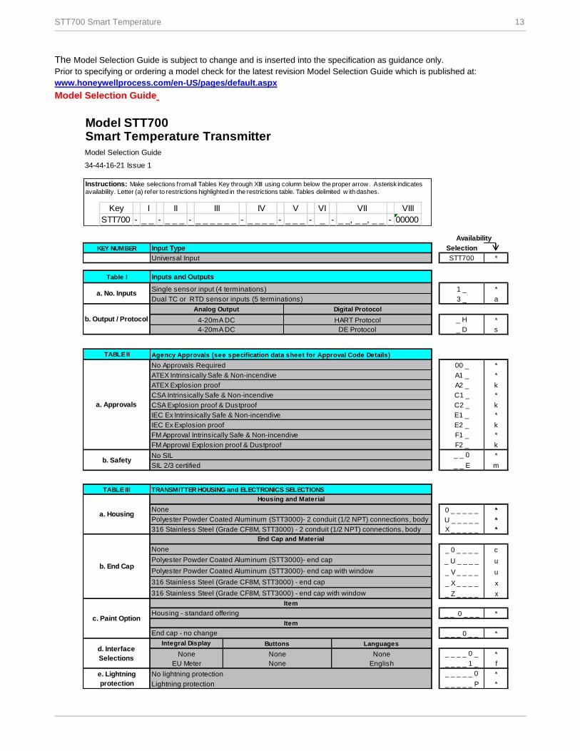
Model STT700Smart Temperature Transmitter
Model Selection Guide
KEY NUMBER Input Type Selection
Universal Input STT700 *
Table I
1 _ *
3 _ a
_ H *
_ D s
TABLE II
00 _ *
A1 _ *
A2 _ k
C1 _ *
C2 _ k
E1 _ *
E2 _ k
F1 _ *
F2 _ k
_ _ 0 *
_ _ E m
TABLE III
0 _ _ _ _ _ *
Polyester Powder Coated Aluminum (STT3000)- 2 conduit (1/2 NPT) connections, body U _ _ _ _ _ *
316 Stainless Steel (Grade CF8M, STT3000) - 2 conduit (1/2 NPT) connections, body X _ _ _ _ _ *
_ 0 _ _ _ _ c
_ U _ _ _ _ u
_ V _ _ _ _ u
_ X _ _ _ _ x
_ Z _ _ _ _ x
_ _ 0 _ _ _ *
_ _ _ 0 _ _ *
Integral Display
None _ _ _ _ 0 _ *
EU Meter _ _ _ _ 1 _ f
_ _ _ _ _ 0 *
_ _ _ _ _ P *
e. Lightning
protection
Housing - standard offering
Item
End cap - no change
c. Paint Option
Lightning protection
ATEX Intrinsically Safe & Non-incendive
ATEX Explosion proof
FM Approval Intrinsically Safe & Non-incendive
FM Approval Explosion proof & Dustproof
IEC Ex Intrinsically Safe & Non-incendive
IEC Ex Explosion proof
None English
d. Interface
Selections
CSA Intrinsically Safe & Non-incendive
TRANSMITTER HOUSING and ELECTRONICS SELECTIONS
Buttons Languages
None
Polyester Powder Coated Aluminum (STT3000)- end cap
Item
End Cap and Material
b. Safety
b. End Cap
a. Housing
a. Approvals
Digital Protocol
HART Protocol
DE Protocol
34-44-16-21 Issue 1
Inputs and Outputs
Single sensor input (4 terminations)
Dual TC or RTD sensor inputs (5 terminations)a. No. Inputs
4-20mA DC
No Approvals Required
Agency Approvals (see specification data sheet for Approval Code Details)
Analog Output
4-20mA DC
Availability
b. Output / Protocol
CSA Explosion proof & Dustproof
Polyester Powder Coated Aluminum (STT3000)- end cap with window
316 Stainless Steel (Grade CF8M, STT3000) - end cap with window
No lightning protection
316 Stainless Steel (Grade CF8M, STT3000) - end cap
None
Housing and Material
SIL 2/3 certified
None None
No SIL
Instructions: Make selections from all Tables Key through XIII using column below the proper arrow. Asterisk indicates
availability. Letter (a) refer to restrictions highlighted in the restrictions table. Tables delimited w ith dashes.
List Price: Price equals the sum of prices for all selections made.
Instructions: Make selections from all Tables Key through XIII using column below the proper arrow. Asterisk indicates
availability. Letter (a) refer to restrictions highlighted in the restrictions table. Tables delimited w ith dashes.
Key I II III IV V VI VII VIII
STT700 - _ _ - _ _ _ - _ _ _ _ _ _ - _ _ _ _ - _ _ _ - _ - _ _, _ _, _ _ - 00000
The Model Selection Guide is subject to change and is inserted into the specification as guidance only.
Prior to specifying or ordering a model check for the latest revision Model Selection Guide which is published at:
www.honeywellprocess.com/en-US/pages/default.aspx
Model Selection Guide
14 STT700 Smart Temperature
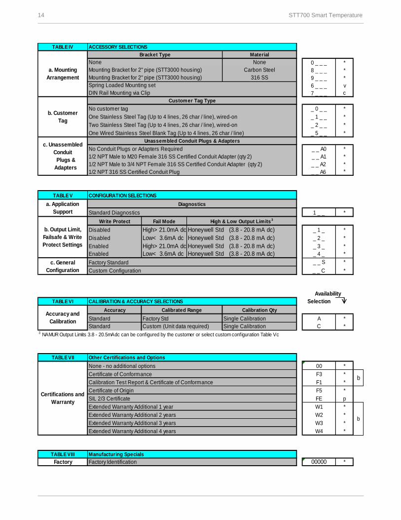
TABLE IV
0 _ _ _ *
8 _ _ _ *
9 _ _ _ *
6 _ _ _ v
7 _ _ _ c
No customer tag _ 0 _ _ *
One Stainless Steel Tag (Up to 4 lines, 26 char / line), wired-on _ 1 _ _ *
Two Stainless Steel Tag (Up to 4 lines, 26 char / line), wired-on _ 2 _ _ *
One Wired Stainless Steel Blank Tag (Up to 4 lines, 26 char / line) _ 5 _ _ *
No Conduit Plugs or Adapters Required _ _ A0 *
1/2 NPT Male to M20 Female 316 SS Certified Conduit Adapter (qty 2) _ _ A1 *
_ _ A2 *
_ _ A6 *
TABLE V
1 _ _ *
Write Protect Fail Mode
Disabled High> 21.0mA dc Honeywell Std (3.8 - 20.8 mA dc) _ 1 _ *
Disabled Low< 3.6mA dc Honeywell Std (3.8 - 20.8 mA dc) _ 2 _ *
Enabled High> 21.0mA dc Honeywell Std (3.8 - 20.8 mA dc) _ 3 _ *
Enabled Low< 3.6mA dc Honeywell Std (3.8 - 20.8 mA dc) _ 4 _ *
_ _ S *
_ _ C *
TABLE VI Selection
Accuracy
Standard Single Calibration A *
Standard Custom (Unit data required) C *3 NAMUR Output Limits 3.8 - 20.5mAdc can be configured by the customer or select custom configuration Table Vc
TABLE VII
00 *
F3 *
F1 *
F5 *
FE p
W1 *
W2 *
W3 *
W4 *
TABLE VIII
Factory 00000 *
Calibrated Range
c. General
Configuration Custom Configuration
DIN Rail Mounting via Clip
Mounting Bracket for 2" pipe (STT3000 housing)
Customer Tag Type
b. Output Limit,
Failsafe & Write
Protect Settings
CONFIGURATION SELECTIONS
a. Application
Support
Diagnostics
Standard Diagnostics
a. Mounting
Arrangement
b. Customer
Tag
None
Mounting Bracket for 2" pipe (STT3000 housing)
c. Unassembled
Conduit
Plugs &
Adapters
Factory Standard
Carbon Steel
Certifications and
Warranty
Material
Unassembled Conduit Plugs & Adapters
1/2 NPT Male to 3/4 NPT Female 316 SS Certified Conduit Adapter (qty 2)
1/2 NPT 316 SS Certified Conduit Plug
Bracket Type
High & Low Output Limits 3
Single Calibration
ACCESSORY SELECTIONS
None
bCalibration Test Report & Certificate of Conformance
Certificate of Origin
SIL 2/3 Certificate
Extended Warranty Additional 1 year
Certificate of Conformance
CALIBRATION & ACCURACY SELECTIONS
Factory Std
b
Calibration Qty
316 SS
Spring Loaded Mounting set
None - no additional options
Availability
Accuracy and
Calibration
Manufacturing Specials
Factory Identification
Other Certifications and Options
Extended Warranty Additional 2 years
Extended Warranty Additional 3 years
Extended Warranty Additional 4 years
STT700 Smart Temperature 15
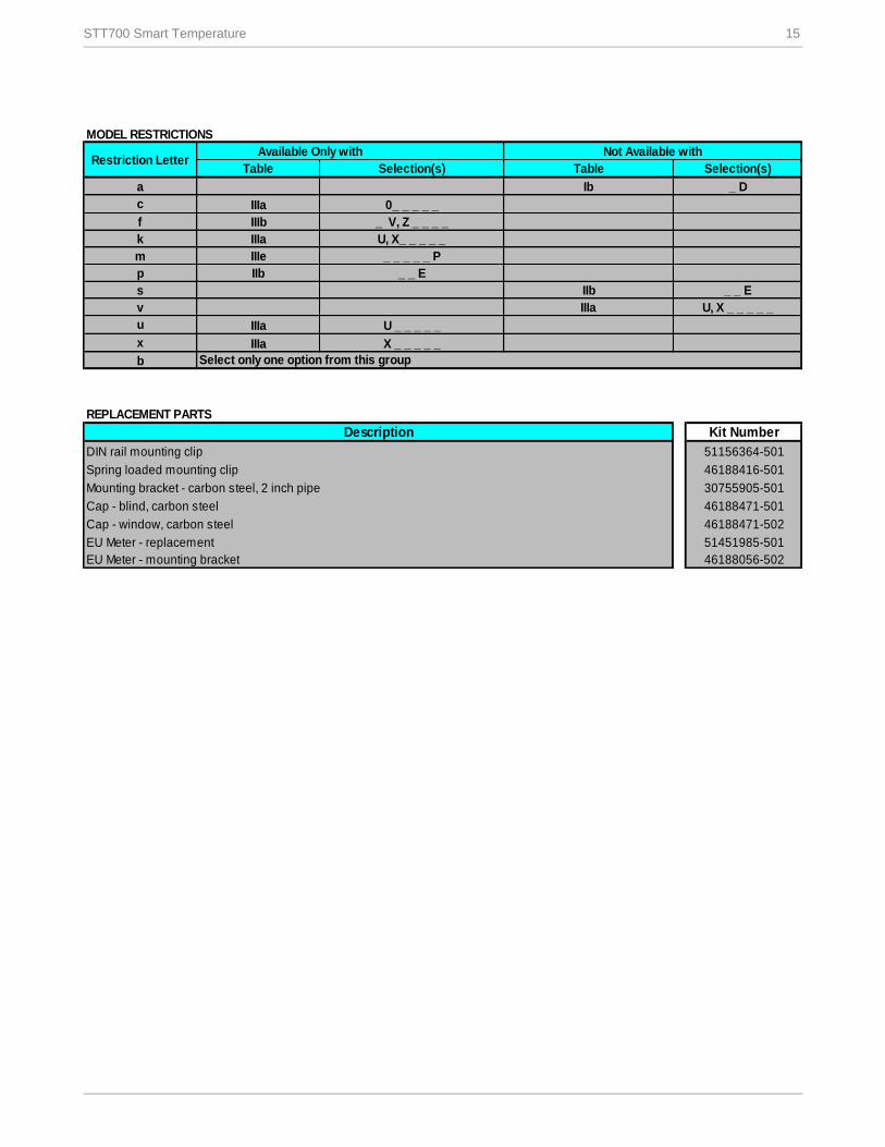
MODEL RESTRICTIONS
Table
a
c IIIa
f IIIb
k IIIa
m IIIe
p IIb
s
v
u IIIa
x IIIa
b
REPLACEMENT PARTS
DIN rail mounting clip
Spring loaded mounting clip
Cap - blind, carbon steel
Cap - window, carbon steel
EU Meter - replacement
EU Meter - mounting bracket
U, X_ _ _ _ _
_ _ _ _ _ P
X _ _ _ _ _
Ib
_ _ E
Restriction Letter
U _ _ _ _ _
IIb _ _ E
IIIa U, X _ _ _ _ _
_ D
0_ _ _ _ _
Select only one option from this group
Description
46188471-501
46188471-502
51451985-501
Kit Number
51156364-501
Mounting bracket - carbon steel, 2 inch pipe
46188056-502
30755905-501
_ V, Z _ _ _ _
46188416-501
Available Only with Not Available with
Selection(s) Table Selection(s)
For more information
To learn more about SmartLine Temperature,
visit www.honeywellprocess.com
Or contact your Honeywell Account Manager
Process Solutions
Honeywell
1250 W Sam Houston Pkwy S
Houston, TX 77042
Honeywell Control Systems Ltd
Honeywell House, Skimped Hill Lane
Bracknell, England, RG12 1EB
34-TT-03-19
July 2017
2017 Honeywell International Inc.
Shanghai City Centre, 100 Jungi Road
Shanghai, China 20061
www.honeywellprocess.com
Sales and Service
For application assistance, current specifications, ordering, pricing, or name of the nearest Authorized Distributor,
contact one of the offices below.
ASIA PACIFIC
Honeywell Process Solutions,
(TAC) hfs-tac-
Australia
Honeywell Limited
Phone: +(61) 7-3846 1255
FAX: +(61) 7-3840 6481
Toll Free 1300-36-39-36
Toll Free Fax:
1300-36-04-70
China – PRC - Shanghai
Honeywell China Inc.
Phone: (86-21) 5257-4568
Fax: (86-21) 6237-2826
Singapore
Honeywell Pte Ltd.
Phone: +(65) 6580 3278
Fax: +(65) 6445-3033
South Korea
Honeywell Korea Co Ltd
Phone: +(822) 799 6114
Fax: +(822) 792 9015
EMEA
Honeywell Process Solutions,
Phone: + 80012026455 or
+44 (0)1202645583
Email: (Sales)
or
(TAC)
AMERICA’S
Honeywell Process Solutions,
Phone: (TAC) 1-800-423-9883 or
215/641-3610
(Sales) 1-800-343-0228
Email: (Sales)
or
(TAC)
Specifications are subject to change without notice.