Embed Size (px)
Citation preview
STUDENT HAND BOOK
Bachelor of Technology
Semester- 3rd
Study Scheme- 2011 onwards
DEPARMENT OF MECHANICAL ENGINEERING
ASRA COLLEGE OF ENGINEERING & TECHNOLOGY
BHAWANIGARH (SANGRUR)
Department of Mechanical Engineering
S.No. Name Contact No. E-mail
1. Prof. Sandeep Sharma 9592800327 [email protected]
2. Er. Omesh Jindal 9465354827 [email protected]
3. Er. Navjot Inder Singh 9780909343 [email protected]
4. 6 Er. Mohit Gaba 9876162828 [email protected]
5. 8 Er. Gurpreet Singh 9463616183 [email protected]
6. 10
Er. Ankur Goyal 9465378245 [email protected]
7. 11
Er. Parminder Singh 9464861902 [email protected]
8. Er. Malkeet Singh 9815889033 [email protected]
9. Er. Jagdeep Singh 9417633753 [email protected]
10. Er. Varinder Singh 9815460584 [email protected]

BTME 301 Strength of Materials – I
Unit –I Simple, Compound Stresses and Strains: Stress and Strain and their types, Hook‟s law, longitudinal and
lateral strain, Poisson‟s ratio, stress-strain diagram for ductile and brittle materials, extension of a bar due to without
and with self weight, bar of uniform strength, stress in a bar, elastic constants and their significance, relation
between elastic constants, Young‟s modulus of elasticity, modulus of rigidity and bulk modulus. Temperature stress
and strain calculation due to axial load and variation of temperature in single and compound bars. Two dimensional
stress system, stress at a point on a plane, principal stresses and principal planes, Mohr‟s circle of stress ellipse of
stress and their applications. Generalized Hook's law, principal stresses related to principal strains.
Unit –II Bending Moment (B.M) and Shear Force (S.F) Diagrams: S.F and B.M definitions; relation between
load, shear force and bending moment; B.M and S.F diagrams for cantilevers, simply supported beams with or
without overhangs, and calculation of maximum B.M and S.F and the point of contra flexure under the following
loads:
a) Concentrated loads
b) Uniformity distributed loads over the whole span or part of span
c) Combination of concentrated and uniformly distributed load
d) Uniformly varying loads
e) Application of moments
Unit –III Bending Stresses In Beams: Assumptions in the simple bending theory; derivation of formula and its
application to beams of rectangular, circular and channel, I and T- sections. Combined direct and bending stresses in
afore-mentioned sections, composite / flitched beams.
Unit –IV Torsion: Derivation of torsion equation and its assumptions and its application to the hollow and solid
circular shafts. Torsional rigidity, combined torsion and bending of circular shafts; principal stress and maximum
shear stresses under combined loading of bending and torsion. Unit –V Columns and struts: Introduction, failure of
columns, Euler‟s formula, Rankine-Gordon‟s formula, Johnson‟s empirical formula for axially loaded columns and
their applications.
Unit –VI Slope and deflection: Relationship between moment, slope and deflection; method of integration,
Macaulay‟s method, moment area method and use of these methods to calculate slope and deflection for the
following:
a) Cantilevers
b) Simply supported beams with or without overhang
c) Under concentrated loads, uniformly distributed loads or combination of concentrated & uniformly distributed
loads.

BTME-302 Theory of Machines-I
Unit –I Basic Concept of machines: Link, Mechanism, Kinematic Pair and Kinematic Chain, Principles of
Inversion, Inversion of a Four Bar Chain, Slider-Crank-Chain and Double Slider-Crank-Chain. Graphical and
Analytical methods for finding: Displacement, Velocity, and Acceleration of mechanisms (including Corliolis
Components).
Unit –II Lower and higher Pairs: Universal Joint, Calculation of maximum Torque, Steering Mechanisms
including Ackerman and Davis approximate steering mechanism, Engine Indicator, Pentograph, Straight Line
Mechanisms, Introduction to Higher Pairs With Examples
Unit –III Belts, Ropes and Chains: Material & Types of belt, Flat and V-belts, Rope & Chain Drives, Idle Pulley,
Intermediate or Counter Shaft Pulley, Angle and Right Angle Drive, Quarter Turn Drive, Velocity Ratio, Crowning
of Pulley, Loose and fast pulley, stepped or cone pulleys, ratio of tension on tight and slack side of belts, Length of
belt, Power transmitted by belts including consideration of Creep and Slip, Centrifugal Tensions and its effect on
power transmission.
Unit –IV Cams: Types of cams and follower, definitions of terms connected with cams. Displacement, velocity and
acceleration diagrams for cam followers. Analytical and Graphical design of cam profiles with various motions
(SHM, uniform velocity, uniform acceleration and retardation, cycloidal Motion). Analysis of follower motion for
circular, convex and tangent cam profiles.
Unit –V Friction Devices: Concepts of friction and wear related to bearing and clutches. Types of brakes function
of brakes. Braking of front and rear tyres of a vehicle. Determination of braking capacity, Types of dynamometers,
(absorption, and transmission).
Unit –VI Flywheels: Turning moment and crank effort diagrams for reciprocating machines‟ Fluctuations of speed,
coefficient of fluctuation of speed and energy, Determination of mass and dimensions of flywheel used for engines
and punching machines.
Unit –VII Governors: Function, types and characteristics of governors. Watt, Porter and Proell governors.Hartnell
and Willson-Hartnell spring loaded governors. Numerical problems related to these governors. Sensitivity, stability,
isochronisms and hunting of governors. Governor effort and power, controlling force curve, effect of sleeve friction.
BTME-303 Machine Drawing
Unit –I Introduction: Principles of Drawing, Requirements of production drawing, Sectioning and conventional
representation, Dimensioning, symbols of standard tolerances, Machining Symbols, introduction and
Familiarization of Code IS: 296
Unit –II Fasteners: Various types of screw threads, types of nuts and bolts, screwed fasteners, welding joints and
riveted joints
Unit –III Assembly and Disassembly:
a) Couplings: Solid or Rigid Coupling, Protected Type Flange coupling, Pin type flexible coupling, muff coupling,
Oldham, universal coupling, claw coupling, cone friction clutch, free hand sketch of single plate friction clutch.
b) Knuckle and cotter joints
c) Pipe and Pipe Fittings: flanged joints, spigot an socket joint, union joint, hydraulic an expansion joint
d) IC Engine Parts: Piston, connecting rod
e) Boiler Mountings: Steam stop valve, feed check valve, safety valve, blow off cock.
f) Bearings: Swivel bearing, thrust bearing, Plummer block, angular plumber block
g) Miscellaneous: Screw Jack, Drill Press Vice, Crane hook, Tool Post, Tail Stock, Drilling Jig.
BTME 304 Applied Thermodynamics-I
Unit –I Combustion: Combustion Equations (Stoichiometric and non- Stoichiometric). Combustion problems in
Boilers and IC engines/Calculations of air fuel ratio, Analysis of products of combustion, Conversion of volumetric
analysis into gravimetric analysis and vice-versa, Actual weight of air supplied, Use of mols, for solution of
combustion problems, Heat of formation, Enthalpy of formation, Enthalpy of reaction, Adiabatic flame temperature.
Unit –II IC Engines Introduction: Actual Engine Indicator diagrams and valve-timing diagrams for two stroke
and four stroke S.I. and C.I. Engines; Construction and Working Principle of Wankel rotary engine; Principle of
simple carburator, Injection systems in Diesel and Petrol Engines( Direct Injection, MPFI in SI and CI Engines,
respectively). Essential requirements for Petrol and Diesel Fuels. Theory of combustion in SI and CI Engines;
Various stages of combustion; Pressure-time/crank - Angle diagrams; Various phenomenon such as turbulence,
squish and swirl, dissociation, pre-ignition/auto- ignition, and after burning etc.; Theory of knocking (ie,.
detonation) in SI and CI Engines; Effect of engine variables on the Delay Period in SI and CI engines; Effect of
various parameters on knock in SI and CI Engines; Methods employed to reduce knock in SI and CI Engines;
Octane and Cetane rating of fuels; Knockmeter; Dopes and inhibitors; Performance curves/maps of SI and CI
Engines; Effect of knocking on engine performance; Effect of compression ratio and air-fuel ratio on power and
efficiency of engine; Variation of engine power with altitude; Supercharging and turbo charging of SI and CI
Engines; Advantages and applications of supercharging; Emissions from SI and CI Engines and methods to
reduce/control them. Logarithmic plotting of PV-diagrams. High speed Engine Indicators.
Unit –III Properties of Steam Pure substance; Steam and its formation at constant pressure: wet, dry,
saturated and super-heated steam; Sensible heat(enthalpy), latent heat and total heat (enthalpy) of steam; dryness

fraction and its determination; degree of superheat and degree of sub-cool; Entropy and internal energy of steam;
Use of Steam Tables and Mollier Chart; Basic thermodynamic processes with steam (isochoric, isobaric, isothermal,
isentropic and adiabatic process) and their representation on T-S Chart and Mollier Charts(h-s diagrams).
Significance of Mollier Charts.
Unit –IV Steam Generators - Definition: Classification and Applications of Steam Generators; Working and
constructional details of fire-tube and water-tube boilers: (Cochran, Lancashire, Babcock and Wilcox boilers);
Merits and demerits of fire-tube and water-tube boilers; Modern high pressure boilers (Benson boiler, La Mont
boiler) and Super critical boilers (Once through boilers-Tower type); Advantages of forced circulation; Description
of boiler mountings and accessories: Different types of Safety Valves, Water level indicator, pressure gauge,
Fusible plug, Feed pump, Feed Check Valve, Blow-off Cock, Steam Stop-Valve, Economiser, Super-heater; Air
pre-heater and Steam accumulators; Boiler performance: equivalent evaporation, boiler efficiency, boiler trial and
heat balance; Types of draught and Calculation of chimney height.
Unit –V Vapour Power Cycle Carnot Cycle and its limitations; Rankine steam power cycle, Ideal and actual; Mean
temperature of heat addition; Effect of pressure, temperature and vacuum on Rankine Efficiency; Rankine Cycle
Efficiency and methods of improving Rankine efficiency: Reheat cycle, Bleeding (feed-water-heating),
Regenerative Cycle, Combined reheat-regenerative cycle; Ideal working fluid; Binary vapour cycle, Combined
power and heating cycles.
Unit –VI Steam Nozzles - Definition, types and utility of nozzles; Flow of steam through nozzles; Condition for
maximum discharge through nozzle; Critical pressure ratio, its significance and its effect on discharge; Area of
throat and at exit for maximum discharge; Effect of friction; Nozzle efficiency; Convergent and convergent-
divergent nozzles; Calculation of Nozzle dimensions (length and diameters of throat and exit); Supersaturated (or
metastable) flow through nozzle.
Unit –VII Steam Turbines Introduction; Classification; Impulse versus Reaction turbines. Simple impulse turbine:
pressure and velocity variation, Velocity diagrams/triangles; Combined velocity diagram/triangle and calculations
for force, axial thrust, work, power, blade efficiency, stage efficiency, maximum work and maximum efficiency,
effect of blade friction on velocity diagram, effect of speed ratio on blade efficiency, condition for axial discharge;
Unit –VIII De Laval Turbine: Compounding of impulse turbines: purpose, types and pressure and velocity
variation, velocity diagrams/triangles, combined velocity diagram/triangle and calculations for force, axial thrust,
work, power, blade efficiency, stage efficiency, overall efficiency and relative efficiency;
Unit –IX Impulse-Reaction Turbine: pressure and velocity variation, velocity diagrams/triangles, Degree of
reaction, combined velocity diagram/triangle and calculations for force, axial thrust, work, power, blade efficiency,
stage efficiency, overall efficiency and relative efficiency, maximum work and maximum efficiency; Calculations
of blade height; Multistaging: Overall efficiency and relative efficiency; Reheating, Reheat factor and condition
curve; Losses in steam turbines; Back pressure and extraction turbines; Co-generation; Economic assessment;
Governing of steam turbines.
Unit –X Steam Condensers Function; Elements of condensing unit; Types of condensers; Dalton‟s law of partial
pressures applied to the condenser problems; Condenser and vacuum efficiencies; Cooling water calculations;
Effect of air leakage; Method to check and prevent air infiltration; Description of air pump and calculation of its
capacity; Cooling towers: function, types and their operation.
BTME 305 Manufacturing Processes –I
Unit –I Introduction: Classification of manufacturing processes, selection criteria for manufacturing processes,
general trends in manufacturing.
Unit –II Casting Processes: Introduction to metal casting. patterns: types, materials and allowances. Moulding
materials: moulding sand compositions and properties, sand testing, types of moulds, moulding machines. Cores:
function, types, core making process, core-prints, chaplets. Elements of gating system and risers and their design.
Design considerations of castings. Melting furnaces, cupola furnace, charge calculations, induction furnaces.
Casting processes: sand casting, shell mould casting, investment casting, permanent mould casting, full mould
casting, vacuum casting, die casting, centrifugal casting, and continuous casting. Metallurgical considerations in
casting, Solidification of metals and alloys, directional solidification, segregation, nucleation and grain growth,
critical size of nucleus. Cleaning and finishing of castings.
Unit –III Welding Processes: Introduction and classification of welding processes, to welding processes,
weldability, welding terminology, general principles, welding positions, and filler metals. Gas welding: principle
and practice, oxy-acetylene welding equipment, oxy-hydrogen welding. Flame cutting. Electric arc welding:
principle, equipment, relative merits of AC & DC arc welding. Welding processes: manual metal arc welding, MIG
welding, TIG welding, plasma arc welding, submerged arc welding. Welding arc and its characteristics, arc
stability, and arc blow. Thermal effects on weldment: heat affected zone, grain size and its control. Electrodes:
types, selection, electrode coating ingredients and their function. Resistance welding: principle and their types i.e.
spot, seam, projection, up-set and flash. Spot welding machine. Advanced welding processes: friction welding,
friction stir welding, ultrasonic welding, laser beam welding, plasma arc welding, electron beam welding, atomic
hydrogen welding, explosive welding, thermit welding, and electro slag welding. Considerations in weld joint
design. Other joining processes: soldering, brazing, braze welding.
Unit –IV Inspection and Testing: Casting defects, their causes and remedies. Welding defects, their causes and
remedies. Destructive and non destructive testing: visual inspection, x-ray radiography, magnetic particle
inspection, dye penetrate test, ultrasonic inspection, eddy current testing, hardness testing, and micro hardness
testing.
BTME-306 Engineering Materials & Metallurgy
Unit –I Crystallography: Atomic structure of metals, atomic bonding in solids, crystal structures, crystal lattice of
body centered cubic, face centered cubic, closed packed hexagonal; crystalline and non crystalline materials;
crystallographic notation of atomic planes; polymorphism and allotropy; imperfection in solids: theoretical yield
strength, point defects, line defects and dislocations, interfacial defects, bulk or volume defects. Diffusion: diffusion
mechanisms, steady-state and non-steady-state diffusion, factors affecting diffusion. Theories of plastic
deformation, recovery, re-crystallization.
Unit –II Phase Transformation: General principles of phase transformation in alloys, phase rule and equilibrium
diagrams, Equilibrium diagrams of Binary systems. Iron carbon equilibrium diagram and various phase
transformations. Time temperature transformation curves (TTT curves): fundamentals, construction and
applications.
Unit –III Heat Treatment: Principles and applications. Processes viz. annealing, normalizing, hardening,
tempering. Surface hardening of steels: Principles of induction and oxyacetylene flame hardening. Procedure for
carburising, nitriding and cyaniding. Harden-ability: determination of harden-ability. Jominy end-quench test.
Defects due to heat treatment and their remedies; effects produced by alloying elements. Composition of alloy
steels.
Unit –IV Ferrous Metals and Their Alloys: Introduction, classification, composition of alloys, effect of alloying
elements (Si, Mn, Ni, Cr, Mo, W, Al) on the structures and properties of steel.
BTME-307 Engineering Materials & Metallurgy Lab
1. Preparation of models/charts related to atomic/crystal structure of metals.
2. Annealing the steel specimen and study the effect of annealing time and temperature on hardness of steel.
3. Hardening the steel specimen and study the effect of quenching medium on hardness of steel.
4. Practice of specimen preparation (cutting, mounting, polishing ,etching) of mild steel, aluminium and hardened
steel specimens.
5. Study of the microstructure of prepared specimens of mild steel, Aluminium and hardened steel.
6. Identification of ferrite and pearlite constituents in given specimen of mild steel.
7. Determination of hardenabilty of steel by Jominy End Quench Test.
BTME-308 Strength of Materials Lab
1. To perform tensile test in ductile and brittle materials and to draw stress-strain curve and to determine various
mechanical properties.
2. To perform compression test on Cast Iron.
3. To perform any one hardness tests (Rockwell, Brinell&Vicker‟s test).
4. To perform impact test to determine impact strength.
5. To perform torsion test and to determine various mechanical properties.
6. To perform Fatigue test on circular test piece.
7. To perform bending test on beam and to determine the Young's modulus and modulus of rupture.
8. Determination of Bucking loads of long columns with different end conditions.
9. To evaluate the stiffness and modulus of rigidity of helical coil spring.
BTME 309 Applied Thermodynamics Lab.
1. Study of construction and operation of 2 stroke and 4 stroke Petrol and Diesel engines using actual engines or
models.
2. To plot actual valve timing diagram of a 4 stroke petrol and diesel engines and study its impact on the
performance of engine.
3. Study of working, construction, mountings and accessories of various types of boilers.
4. To perform a boiler trial to estimate equivalent evaporation and efficiency of a fire tube/ water tube boiler.
5. Determination of dryness fraction of steam and estimation of brake power, Rankine efficiency, relative
efficiency, generator efficiency, and overall efficiency of an impulse steam turbine and to plot a Willian‟s line.
6. Determine the brake power, indicated power, friction power and mechanical efficiency of a multi cylinder petrol
engine running at constant speed (Morse Test).
7. Performance testing of a diesel engine from no load to full load (at constant speed) for a single cylinder/ multi-
cylinder engine in terms of brake power, indicated power, mechanical efficiency and specific fuel consumption and
to measure the smoke density. Draw/obtain power consumption and exhaust emission curves. Also make the heat
balance sheet.
8. Performance testing of a petrol engine from no load to full load (at constant speed) for a single cylinder/ multi-
cylinder engine in terms of brake power, indicated power, mechanical efficiency and specific fuel consumption and
to measure the exhaust emissions. Also draw/obtain power consumption and exhaust emission curves.
9. Study of construction and operation of various types of steam condensers and cooling towers.
BTME 301 Strength of Materials – I
Assignment No.1
1. Derive an expression to calculate the deformation in a bar due to its own weight.
2. Draw Stress-Strain Diagram of Ductile materials. Explain it?
3. Derive an expression to calculate volumetric strain in bar of circular cross-section subjected to
force in one direction only.
4. Explain the concept of Thermal Stresses.
5. Explain the various Mechanical Properties of Materials.
Assignment No.2
1. Explain the concept of Complementary Shear Stress.
2. Find the relationship between Plane of maximum shear stress and Principal Planes.
3. Write down the steps to draw a Mohr Circle for Biaxial Stress Condition with shear Stresses.
Assignment No.3
1. Define the following in case of a loaded beam
(a) Bending moment
(b) Shear force
(c) Point of contraflexure
2. How do you find the maximum bending moment in a beam?
3. What is a beam? Explain the various types of beams.
Assignment No.4
1. Compare the Hollow and Solid Shafts by their Strength.
2. Derive an expression to find Euler‟s load for a column with both ends hinged.
3. Derive the Bending formula considering all the assumptions in Bending Theory.
4. Write a short on Flitched Beams.
Assignment No. 5
1. Derive relationship between moment, slope and deflection.
2. Discuss moment area method to calculate deflection.
3. Discuss methods of integration.
BTME-302 Theory of Machines-I
ASSIGNMENT NO. 1
Q.1 what is compound mechanism
Q.2 Describe the working of pantograph
Q.3 what is the difference between machine and mechanism
Q.4 Explain elliptical trammel
Q.5 Explain Ackermann steering mechanism
Q.6 Explain engine indicator
ASSIGNMENT NO. 2
Q.1 What do you mean by creep
Q.2 What is crowing of pulley
Q.3 Derive the equation T1 – T2 / T2 - TC = euo for belt derive
Q.4 Explain
1) Centrifugal tension
2) Initial tension in belt
ASSIGNMENT NO. 3
Q.1 What is pressure angle in brake
Q.2 Name the various types of cam and followers
Q.3 Difference between brake and dynometer
Q.4 Derive an expression for the retardation produced when the brake are applied to the rear wheels of a
wheels of a vehicle going up inclined road
Q.5 Derive an expression for the friction moment of a collar thrust bearing
ASSIGNMENT NO. 4
Q.1 Define coefficient of fluctuation of speed in flywheel
Q.2 What is function of flywheel
Q.3 Derive the expression for the stresses in the flywheel rim and arm
Q.4 What is turning moment diagram draw and explain the turning moment diagram for a four stroke
single cylinder internal combustion engine
ASSIGNMENT NO. 5
Q.1 Explain power of governor
Q.2 What is stability in case of governors
Q.3 Distinguish between flywheel and governor
Q.4 Define sensitivity, stability, isochronism and hunting
Q.5 Derive an expression for the equilibrium speed of porter governor
BTME 304 Applied Thermodynamics-I
ASSIGNMENT NO:-1
1. Define various stages of combustion pressure angle diagram?
2. Explain the term turbulence ,squish,and swirl and pre ignition?
3. What is the octane and cetane rating of fuels?
4. What is the working of two stroke petrol engine?
5. What do you understand the term supercharging and supercharger?
ASSIGNMENT NO:-2
1. How the boiler are classified ?Compare the fire tube boiler and water tube boiler?.
2. Explain the working of a benson boiler with a neat sketch .List its advantages?
3. Explain babcock and Wilcox boiler
4. State the function of feed check valve, blow off cock and fusible plug.
5. What are the basic component of a steam power plant? Explain the function of each component?.
6. What do you mean by binary vapour cycle?Explain mercury –steam binary vapour cycle with the help
of (T-S) diagram? .
ASSIGNMENT NO:-3
1. Derive the relation between area ,velocity and pressure in nozzles flow?
2. Derive an expression for critical pressure ratio for adiabatic frictionless expansion of steam from a
given intial velocity?.
3. What is the diff between impulse and reaction turbine?.
4. State the condition for maximum efficiency for impulse turbine?.
5. Derive the expression for maximum blade efficiency in a single stage impulse turbine?
ASSIGNMENT NO:-4
1. Discuss the method of velocity compounding of an impulse turbine for achieving rotor speed
reduction.
2. Enumerate the diiferent loss in steam turbine?.
3. What are methods of governing a steam turbine ? Describe any one method of governing?
4. Explain the function of the blading of a reaction turbine?.
5. Explain the principle of impulse turbine?
ASSIGNMENT NO:-5
1. Explain the evaporative condenser?.
2. Compare the jet condenser with surface condenser?.
3. State the Dalton,s law of partial pressure ? how it is applied to condenser application?
BTME 305 Manufacturing Processes –I
ASSIGNMENT:-1
1.Define the term „Manufacturing‟
2.Dicuss the importance of computers in manufacturing
3. Classify the manufacturing processes.
4. What is the most important plus point of deformation processes of manufacturing?
ASSIGNMENT:-2
1. Write the advantages of casting process
2. Compare the different types of sand moulds.
3. Explain the function of a pattern in casting.
4. Write on: finishing of patterns.
5. Discuss the various pattern allowances.
ASSIGNMENT:-3
1. write on „pattern materials‟ used in sand moulding
2. What is core venting?
3. Why the cores are reinforced?
4. write on „finishing and coating of cores‟
5. What is vacuum die casting?
ASSIGNMENT:-4
1. Sketch the two polarities of dc supply & compare these for welding processes.
2. For what commercial application can the EBW process be economical?
3. Write about the various soldering techniques used.
4. What effect does carbon content of steel have on weld ability?
ASSIGNMENT:-5
1. Write briefly on „testing and inspection of welded joints‟.
2. Name the ten methods of arc welding.
3. List advantages of arc welding over gas welding processes.
4. What is eddy current testing?
5. Write a short note on:-
a) Destructive and non -destructive testing
b) visual inspection
c) X-ray radiography
BTME-306 Engineering Materials & Metallurgy
Assignment No.1
1. What is atomic structure of metals, also explain atomic bonding in solids
2 What is crystal structure?
3 Explain BCC,FCC and hexagonal packing.
4 Explain Imperfection in crystal
5 Explain crystalline and non-crystalline materials
Assignment No.2
1.Explain Diffusion in detail.
2 Explain theories of plastic deformation.
3 Explain general principles of phase transformation in alloys.
Assignment No.3
1. Explain Iron carbon equilibrium diagram and various phase transformations
2. Explain TTT curves fundamentals, construction and applications
3. Explain Heat Treatment: Principles and applications.
4. Explain annealing, normalizing,hardening and tempering
5. Explain surface hardening of steels
Assignment No.4
1 Explain carburizing process.
2 Explain nitriding process.
3 Explain cyaniding process.
4. Explain Jominy end-quench test
5. What are Effect of alloying elements on steel?
Assignment No.5
1. Explain the difference between annealing and normalizing.
2. What is hardenability and how is it measured?
3. How is hardening attained by quenching?
4. What are the effects of alloying elements on properties of steel?
5. Write various defects in heat treatment and their remedies.
BTME-307 Engineering Materials & Metallurgy Lab
Experiment No. 2
OBJECTIVE: Annealing the steel specimen and study the effect of annealing time and temperature on hardness
of steel.
THEORY:
Annealing: Annealing is a heat treatment process. The objects of annealing are:
a) To soften the metals
b) To improve machinability
c) To refine grain size due to phase recrystallisation
d) To increase ductility of metal
e) To prepare steel for subsequent treatment
f) To modify electrical and magnetic properties
g) To relieve internal stresses
h) To remove gases
i) To produce a definite microstructure
The process of annealing is done in either of following ways:
1) Full Annealing
2) Isothermal Annealing
3) Process or Sub-Critical Annealing and
4) Spheroidisation
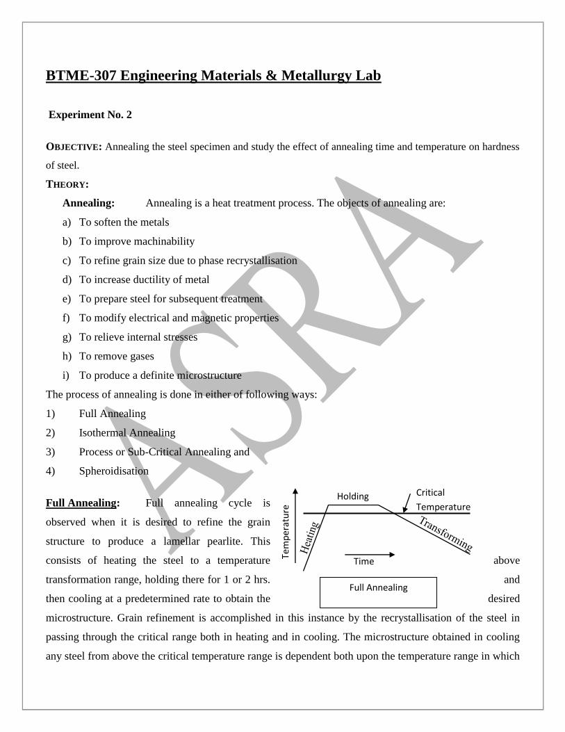
Full Annealing: Full annealing cycle is
observed when it is desired to refine the grain
structure to produce a lamellar pearlite. This
consists of heating the steel to a temperature above
transformation range, holding there for 1 or 2 hrs. and
then cooling at a predetermined rate to obtain the desired
microstructure. Grain refinement is accomplished in this instance by the recrystallisation of the steel in
passing through the critical range both in heating and in cooling. The microstructure obtained in cooling
any steel from above the critical temperature range is dependent both upon the temperature range in which
Time
Holding
Tem
per
atu
re
Critical
Temperature
Full Annealing
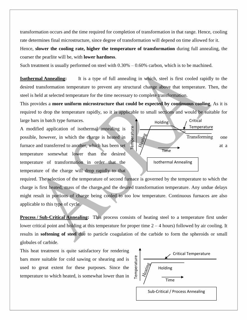
transformation occurs and the time required for completion of transformation in that range. Hence, cooling
rate determines final microstructure, since degree of transformation will depend on time allowed for it.
Hence, slower the cooling rate, higher the temperature of transformation during full annealing, the
coarser the pearlite will be, with lower hardness.
Such treatment is usually performed on steel with 0.30% – 0.60% carbon, which is to be machined.
Isothermal Annealing: It is a type of full annealing in which, steel is first cooled rapidly to the
desired transformation temperature to prevent any structural change above that temperature. Then, the
steel is held at selected temperature for the time necessary to complete transformation.
This provides a more uniform microstructure that could be expected by continuous cooling. As it is
required to drop the temperature rapidly, so it is applicable to small sections and would be suitable for
large bars in batch type furnaces.
A modified application of isothermal annealing is
possible, however, in which the charge is heated in one
furnace and transferred to another, which has been set at a
temperature somewhat lower than the desired
temperature of transformation in order that the
temperature of the charge will drop rapidly to that
required. The selection of the temperature of second furnace is governed by the temperature to which the
charge is first heated, mass of the charge and the desired transformation temperature. Any undue delays
might result in portions of charge being cooled to too low temperature. Continuous furnaces are also
applicable to this type of cycle.
Process / Sub-Critical Annealing: This process consists of heating steel to a temperature first under
lower critical point and holding at this temperature for proper time 2 – 4 hours) followed by air cooling. It
results in softening of steel due to particle coagulation of the carbide to form the spheroids or small
globules of carbide.
This heat treatment is quite satisfactory for rendering
bars more suitable for cold sawing or shearing and is
used to great extent for these purposes. Since the
temperature to which heated, is somewhat lower than in
Time
Holding
Tem
per
atu
re
Critical
Temperature
Isothermal Annealing
Time
Holding
Tem
per
atu
re
Critical Temperature
Sub-Critical / Process Annealing
full annealing, there is less scaling and warping is controllable.
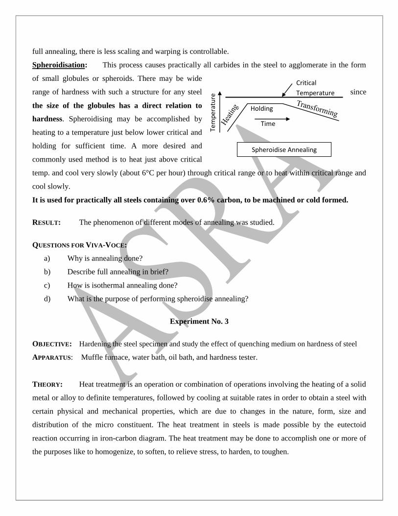
Spheroidisation: This process causes practically all carbides in the steel to agglomerate in the form
of small globules or spheroids. There may be wide
range of hardness with such a structure for any steel since
the size of the globules has a direct relation to
hardness. Spheroidising may be accomplished by
heating to a temperature just below lower critical and
holding for sufficient time. A more desired and
commonly used method is to heat just above critical
temp. and cool very slowly (about 6°C per hour) through critical range or to heat within critical range and
cool slowly.
It is used for practically all steels containing over 0.6% carbon, to be machined or cold formed.
RESULT: The phenomenon of different modes of annealing was studied.
QUESTIONS FOR VIVA-VOCE:
a) Why is annealing done?
b) Describe full annealing in brief?
c) How is isothermal annealing done?
d) What is the purpose of performing spheroidise annealing?
Experiment No. 3
OBJECTIVE: Hardening the steel specimen and study the effect of quenching medium on hardness of steel
APPARATUS: Muffle furnace, water bath, oil bath, and hardness tester.
THEORY: Heat treatment is an operation or combination of operations involving the heating of a solid
metal or alloy to definite temperatures, followed by cooling at suitable rates in order to obtain a steel with
certain physical and mechanical properties, which are due to changes in the nature, form, size and
distribution of the micro constituent. The heat treatment in steels is made possible by the eutectoid
reaction occurring in iron-carbon diagram. The heat treatment may be done to accomplish one or more of
the purposes like to homogenize, to soften, to relieve stress, to harden, to toughen.
Time
Holding
Tem
per
atu
re
Critical
Temperature
Spheroidise Annealing
There are three main stages in all heat treatment cycle.
1. Heating the metal or alloy to the predetermined heat treating temperature.
2. Soaking the metal at that temperature until the structure becomes uniform throughout the
section.
3. Cooling the metal at some predetermined rate will cause the formation of desirable structures
in the metal.
PROCEDURE
A. First all the samples are put in the furnace at 900°C for ½ hr.
B. After half hr. the samples are taken out one by one.
C. One sample should be quenched in water.
D. Another samples is immersed to cool in oil.
E. The next sample should be kept in open air to get air cooled.
F. Another sample is kept in the furnace itself to get cooled down to room temperature in
the furnace.
G. As each samples gets cooled, its faces are ground and polished to get an even surface.
H. Nextly, hardness is checked and a graph is plotted, if desired.
I. A piece from the hardened end of each sample is cut and prepared for metallographic
examination and its microstructure is studied.
PRECAUTIONS:
1. For quenching, the sample should be immediately transferred from the furnace to the water/oil
bath.
2. The quenching media should be agitated.
3. The specimen should be well grinded and polished before measuring hardness.
4. Hardness should be checked in cold state.
QUESTIONS FOR VIVA-VOCE:
a) What information can be obtained from the study of microstructure?
b) How is hardness related to the rate of cooling?
c) What do you mean by austenizing temperature?
d)
Experiment No. 4
OBJECTIVE: Practice of specimen preparation (cutting, mounting, polishing ,etching) of mild steel,
aluminium and hardened steel specimens.
APPARATUS: Sample specimens, emery papers, polishing wheel, etchant, metallurgical microscope.
THEORY: Microstructural examination can provide quantitative information about the grain size of
specimens, grain shapes, amount of interfacial area per unit volume, dimensions of constituent phases,
amount of distribution of the phases and effect of heat treatment on mechanical properties.
Microstructural examination in other words is also called Metallography, which is a specialized discipline
in the science of materials technology. Several necessary steps in doing metallography of materials
include:
A) Selection of sample or specimen
B) Polishing it to make it flat and mirror smooth Sample preparation
C) Etching to create relief on the surface to be observed
D) Observing the structures on microscope
E) Sketching or photographing the structures Observation and recording
PROCEDURE: A sample specimen is prepared observing following procedure:
a) Selection of Specimen
A specimen is so selected that it represents, as far as possible, the whole section or the entire piece. Only a
small piece can be used and only a plane or flat section can be observed.
b) Cutting the Specimen
Having selected a particular area in whole mass, specimen is cut. Hacksaw or power hacksaw may be
taken into application. The edges of specimen are beveled or chamfered slightly to prevent tearing of
polishing cloth / emery paper.
d) Obtaining flat specimen surface
Primarily, application of a fairly coarse file or grinding is done to achieve a flat surface. Then, using
emery papers of progressively finer grades, grinding of the specimen is done.
e) Polishing to fine finish
The cloth covered polishing wheels and fine abrasive slurry is used to produce a final mirror-finish. The
wheel is first washed off the old abrasive and then some fine abrasive is applied on wet cloth.
f) Etching
There are specific etchants suitable for various purposes and metals. To etch a specimen, it is first ensured
to be clean and dry. Then a small amount of etchant is taken into a white porcelain evaporating dish. Then,
etchant is dropped over the surface with help of small tuft of clean cotton. The surface should be kept
completely covered with etchant liquid. Etching turns the shiny mirror appearance into a slightly cloudy
mirror one.
Then, etchant is removed with flowing tap water and quickly the specimen is blown dry.
Then, using the metallurgical microscope, the microstructure of the specimen is observed.
PRECAUTIONS:
A) At any instance while polishing, or afterwards, never touch the polished surface with fingers,
because it deposits a film or tarnish, hiding the microstructure of specimen.
B) Every polishing scratch should be removed completely before proceeding further.
C) Specific etchant should be used corresponding to metal, so that any chemical attack or corrosion
does not take place.
D) Etchant should be washed off immediately after etching and specimen should be immediately
blown dry after washing off the etchant.
E) The spattering of etchant in eyes, or on clothes should be avoided.
F) Hands should be thoroughly washed after using an etchant.
G) Heat due to friction should be avoided at every stage(cutting, grinding or polishing etc.) as it can
cause alteration in microstructure.
Experiment No. 5
OBJECTIVE: Study of the microstructure of prepared specimens of mild steel, Aluminium and hardened
steel. APPARATUS: Sample specimens, emery papers, polishing wheel, etchant, metallurgical microscope.
THEORY: Microstructural examination can provide quantitative information about the grain size of
specimens, grain shapes, amount of interfacial area per unit volume, dimensions of constituent phases,
amount of distribution of the phases and effect of heat treatment on mechanical properties.
Microstructural examination in other words is also called Metallography, which is a specialized discipline
in the science of materials technology. Several necessary steps in doing metallography of materials
include:
1. Selection of sample or specimen
2. Polishing it to make it flat and mirror smooth Sample preparation
3. Etching to create relief on the surface to be observed
4. Observing the structures on microscope
5. Sketching or photographing the structures Observation and recording
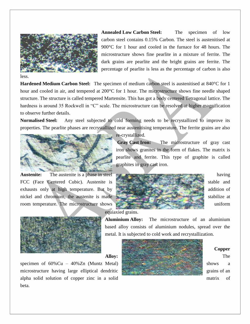
Annealed Low Carbon Steel: The specimen of low
carbon steel contains 0.15% Carbon. The steel is austenitised at
900°C for 1 hour and cooled in the furnace for 48 hours. The
microstructure shows fine pearlite in a mixture of ferrite. The
dark grains are pearlite and the bright grains are ferrite. The
percentage of pearlite is less as the percentage of carbon is also
less.
Hardened Medium Carbon Steel: The specimen of medium carbon steel is austenitised at 840°C for 1
hour and cooled in air, and tempered at 200°C for 1 hour. The microstructure shows fine needle shaped
structure. The structure is called tempered Martensite. This has got a body centered Tetragonal lattice. The
hardness is around 35 Rockwell in “C” scale. The microstructure can be resolved at higher magnification
to observe further details.
Normalised Steel: Any steel subjected to cold forming needs to be recrystallized to improve its
properties. The pearlite phases are recrystallized near austenitising temperature. The ferrite grains are also
re-crystallized.
Gray Cast Iron: The microstructure of gray cast
iron shows granites in the form of flakes. The matrix is
pearlite and ferrite. This type of graphite is called
graphites in gray cast iron.
Austenite: The austenite is a phase in steel having
FCC (Face Centered Cubic). Austenite is stable and
exhausts only at high temperature. But by addition of
nickel and chromium, the austenite is made stabilize at
room temperature. The microstructure shows uniform
equiaxied grains.
Aluminium Alloy: The microstructure of an aluminium
based alloy consists of aluminium nodules, spread over the
metal. It is subjected to cold work and recrystallization.
Copper
Alloy: The
specimen of 60%Cu – 40%Zn (Muntz Metal) shows a
microstructure having large elliptical dendritic grains of an
alpha solid solution of copper zinc in a solid matrix of
beta.

Tool Steel: The specimen of an oil hardened tool steel
(austenitised and quenched in oil and tempered) shows a
microstructure consisting of martensite and cementite. Some
bright areas are retained austenite.
Malleable Cast Iron: It is a result of annealing white iron of an
appropriate chemical composition, to convert the
carbon that is combined in the cementite (Fe3C) to
elemental carbon (Graphite) in the form of temper
carbon. The matrix of malleable Cast Iron is commonly
less ferrite and pearlite.
Magnesium Alloy: The specimen of an aluminium
based magnesium alloys subjected to cold work and
recrystallisation was studied. The grains are equiaxed
Mg17Al12 grains.
Nickel
Alloy: A Nickel based heat resisting
alloy was studied. The microstructure consists of
austenitic grains of solid solution of Nickel with alloy
carbides of chromium, iron etc. They are denoted by
dark particles.
PRECAUTIONS:
H) At any instance while polishing, or afterwards, never touch the polished surface with fingers,
because it deposits a film or tarnish, hiding the microstructure of specimen.
I) Every polishing scratch should be removed completely before proceeding further.
J) Specific etchant should be used corresponding to metal, so that any chemical attack or corrosion
does not take place.
K) Etchant should be washed off immediately after etching and specimen should be immediately
blown dry after washing off the etchant.
L) The spattering of etchant in eyes, or on clothes should be avoided.
M) Hands should be thoroughly washed after using an etchant.
N) Heat due to friction should be avoided at every stage(cutting, grinding or polishing etc.) as it can
cause alteration in microstructure.
QUESTIONS FOR VIVA-VOCE
a) What do you understand by Hyper- & Hypo-eutectoid steels?
b) What is the importance of studying the microstructure of metals?
c) What is the general procedure followed to examine microstructure of a particular sample?
d) Why is etching done?
e) What precautions should be observed while using an etchant (while performing etching operation)
Experiment No. 6
OBJECTIVE: Identification of ferrite and pearlite constituents in given specimen of mild steel.
APPARATUS: Samples of different carbon compositions, a muffle furnace.
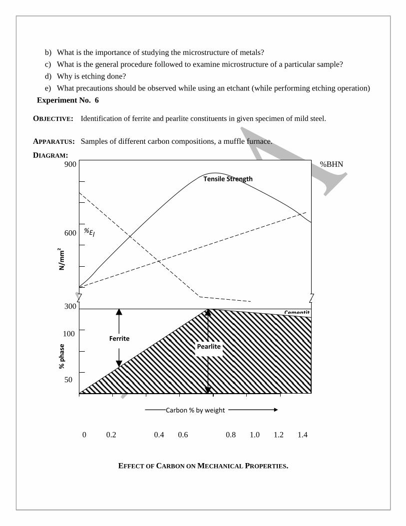
DIAGRAM:
900 %BHN
600
300
100
50
0 0.2 0.4 0.6 0.8 1.0 1.2 1.4
EFFECT OF CARBON ON MECHANICAL PROPERTIES.
N/m
m2
% p
has
e
Carbon % by weight
Tensile Strength
%El
BHN
Pearlite Ferrite
Cementit
e
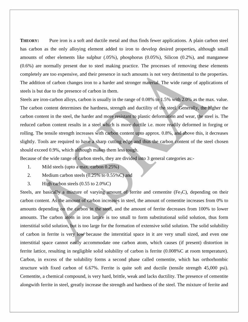
THEORY: Pure iron is a soft and ductile metal and thus finds fewer applications. A plain carbon steel
has carbon as the only alloying element added to iron to develop desired properties, although small
amounts of other elements like sulphur (.05%), phosphorus (0.05%), Silicon (0.2%), and manganese
(0.6%) are normally present due to steel making practice. The processes of removing these elements
completely are too expensive, and their presence in such amounts is not very detrimental to the properties.
The addition of carbon changes iron to a harder and stronger material. The wide range of applications of
steels is but due to the presence of carbon in them.
Steels are iron-carbon alloys, carbon is usually in the range of 0.08% to 1.5% with 2.0% as the max. value.
The carbon content determines the hardness, strength and ductility of the steel. Generally, the higher the
carbon content in the steel, the harder and more resistant to plastic deformation and wear, the steel is. The
reduced carbon content results in a steel which is more ductile i.e. more readily deformed in forging or
rolling. The tensile strength increases with carbon content upto approx. 0.8%, and above this, it decreases
slightly. Tools are required to have a sharp cutting edge and thus the carbon content of the steel chosen
should exceed 0.9%, which although makes them less tough.
Because of the wide range of carbon steels, they are divided into 3 general categories as:-
1. Mild steels (upto a max. carbon 0.25%)
2. Medium carbon steels (0.25% to 0.55%C) and
3. High carbon steels (0.55 to 2.0%C)
Steels, are basically a mixture of varying amount of ferrite and cementite (Fe3C), depending on their
carbon content. As the amount of carbon increases in steel, the amount of cementite increases from 0% to
amounts depending on the carbon in the steel, and the amount of ferrite decreases from 100% to lower
amounts. The carbon atom in iron lattice is too small to form substitutional solid solution, thus form
interstitial solid solution, but is too large for the formation of extensive solid solution. The solid solubility
of carbon in ferrite is very low because the interstitial space in it are very small sized, and even one
interstitial space cannot easily accommodate one carbon atom, which causes (if present) distortion in
ferrite lattice, resulting in negligible solid solubility of carbon is ferrite (0.008%C at room temperature).
Carbon, in excess of the solubility forms a second phase called cementite, which has orthorhombic
structure with fixed carbon of 6.67%. Ferrite is quite soft and ductile (tensile strength 45,000 psi).
Cementite, a chemical compound, is very hard, brittle, weak and lacks ductility. The presence of cementite
alongwith ferrite in steel, greatly increase the strength and hardness of the steel. The mixture of ferrite and
cementite is called pearlite. In iron –carbon eutectoid reaction, austenite of eutectoid composition, on
cooling, gives a simultaneous formation of ferrite and cementite – the mixture is lamellar, i.e. composed
of alternate layers of ferrite and cementite, as a whole called pearlite. The amount of cementite increases
continuously with the increase of carbon, but the amount of pearlite increases continuously only upto
0.8% carbon in steels.
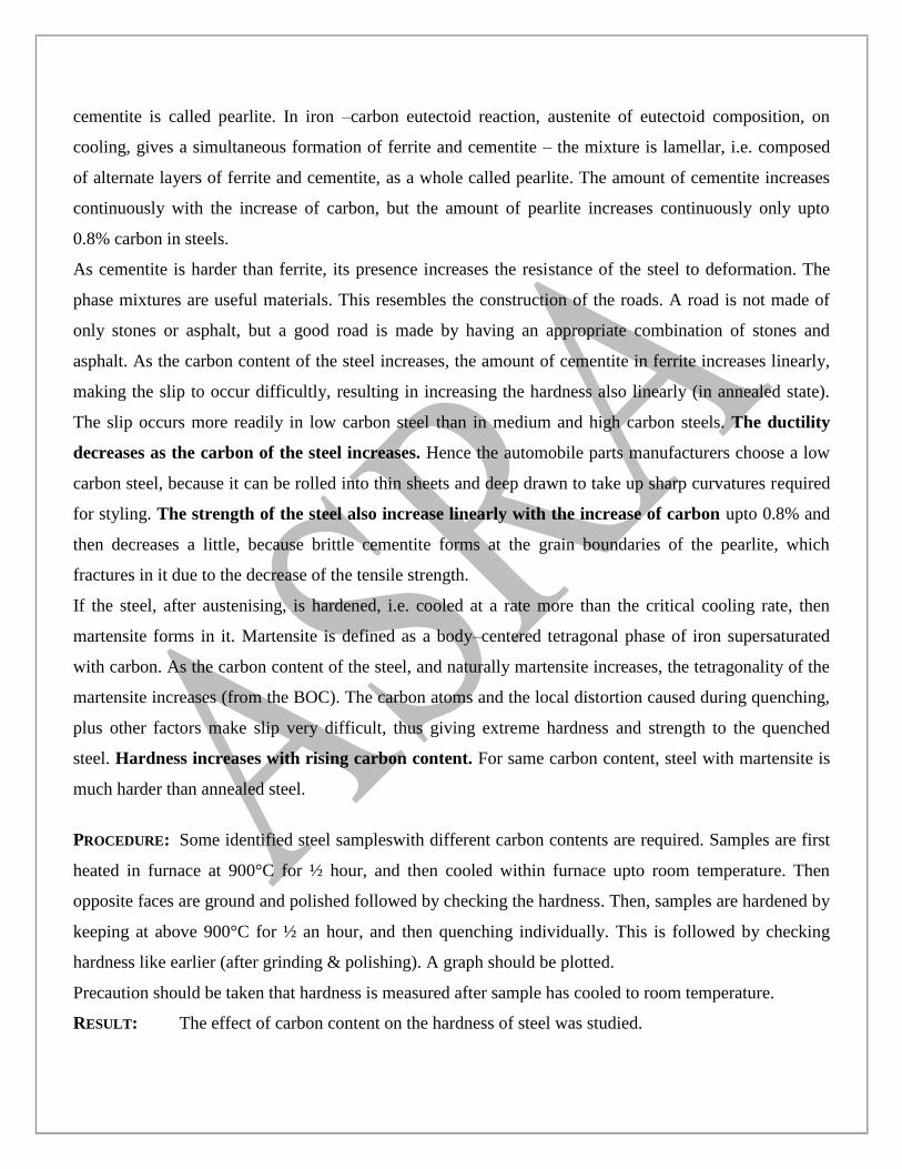
As cementite is harder than ferrite, its presence increases the resistance of the steel to deformation. The
phase mixtures are useful materials. This resembles the construction of the roads. A road is not made of
only stones or asphalt, but a good road is made by having an appropriate combination of stones and
asphalt. As the carbon content of the steel increases, the amount of cementite in ferrite increases linearly,
making the slip to occur difficultly, resulting in increasing the hardness also linearly (in annealed state).
The slip occurs more readily in low carbon steel than in medium and high carbon steels. The ductility
decreases as the carbon of the steel increases. Hence the automobile parts manufacturers choose a low
carbon steel, because it can be rolled into thin sheets and deep drawn to take up sharp curvatures required
for styling. The strength of the steel also increase linearly with the increase of carbon upto 0.8% and
then decreases a little, because brittle cementite forms at the grain boundaries of the pearlite, which
fractures in it due to the decrease of the tensile strength.
If the steel, after austenising, is hardened, i.e. cooled at a rate more than the critical cooling rate, then
martensite forms in it. Martensite is defined as a body–centered tetragonal phase of iron supersaturated
with carbon. As the carbon content of the steel, and naturally martensite increases, the tetragonality of the
martensite increases (from the BOC). The carbon atoms and the local distortion caused during quenching,
plus other factors make slip very difficult, thus giving extreme hardness and strength to the quenched
steel. Hardness increases with rising carbon content. For same carbon content, steel with martensite is
much harder than annealed steel.
PROCEDURE: Some identified steel sampleswith different carbon contents are required. Samples are first
heated in furnace at 900°C for ½ hour, and then cooled within furnace upto room temperature. Then
opposite faces are ground and polished followed by checking the hardness. Then, samples are hardened by
keeping at above 900°C for ½ an hour, and then quenching individually. This is followed by checking
hardness like earlier (after grinding & polishing). A graph should be plotted.
Precaution should be taken that hardness is measured after sample has cooled to room temperature.
RESULT: The effect of carbon content on the hardness of steel was studied.
QUESTIONS FOR VIVA-VOCE:
a) What is hardness?
b) What is the role of carbon content in a steel?
c) What aims are achieved by varying carbon %age in a particular steel?
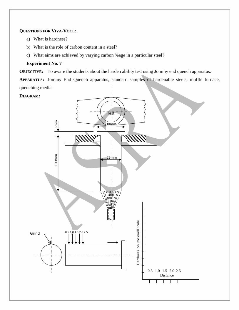
Experiment No. 7
OBJECTIVE: To aware the students about the harden ability test using Jominy end quench apparatus.
APPARATUS: Jominy End Quench apparatus, standard samples of hardenable steels, muffle furnace,
quenching media.
DIAGRAM:
0.5 1.0 1.5 2.0 2.5
Distance
Test
Piece
25mm
30mm
10
0m
m
5m
m
Grind 0.5 1.0 1.5 2.0 2.5
Har
dn
ess
on
Ro
ckw
ell S
cale
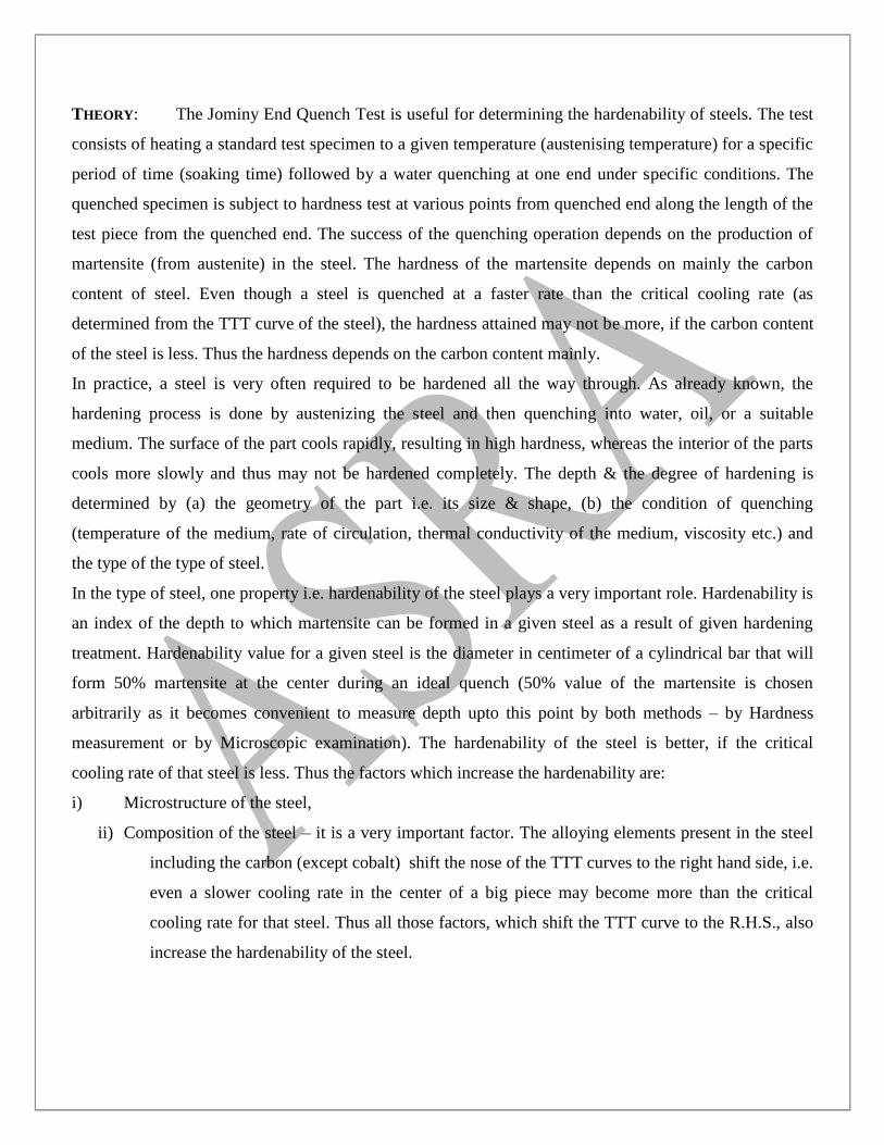
THEORY: The Jominy End Quench Test is useful for determining the hardenability of steels. The test
consists of heating a standard test specimen to a given temperature (austenising temperature) for a specific
period of time (soaking time) followed by a water quenching at one end under specific conditions. The
quenched specimen is subject to hardness test at various points from quenched end along the length of the
test piece from the quenched end. The success of the quenching operation depends on the production of
martensite (from austenite) in the steel. The hardness of the martensite depends on mainly the carbon
content of steel. Even though a steel is quenched at a faster rate than the critical cooling rate (as
determined from the TTT curve of the steel), the hardness attained may not be more, if the carbon content
of the steel is less. Thus the hardness depends on the carbon content mainly.
In practice, a steel is very often required to be hardened all the way through. As already known, the
hardening process is done by austenizing the steel and then quenching into water, oil, or a suitable
medium. The surface of the part cools rapidly, resulting in high hardness, whereas the interior of the parts
cools more slowly and thus may not be hardened completely. The depth & the degree of hardening is
determined by (a) the geometry of the part i.e. its size & shape, (b) the condition of quenching
(temperature of the medium, rate of circulation, thermal conductivity of the medium, viscosity etc.) and
the type of the type of steel.
In the type of steel, one property i.e. hardenability of the steel plays a very important role. Hardenability is
an index of the depth to which martensite can be formed in a given steel as a result of given hardening
treatment. Hardenability value for a given steel is the diameter in centimeter of a cylindrical bar that will
form 50% martensite at the center during an ideal quench (50% value of the martensite is chosen
arbitrarily as it becomes convenient to measure depth upto this point by both methods – by Hardness
measurement or by Microscopic examination). The hardenability of the steel is better, if the critical
cooling rate of that steel is less. Thus the factors which increase the hardenability are:
i) Microstructure of the steel,
ii) Composition of the steel – it is a very important factor. The alloying elements present in the steel
including the carbon (except cobalt) shift the nose of the TTT curves to the right hand side, i.e.
even a slower cooling rate in the center of a big piece may become more than the critical
cooling rate for that steel. Thus all those factors, which shift the TTT curve to the R.H.S., also
increase the hardenability of the steel.
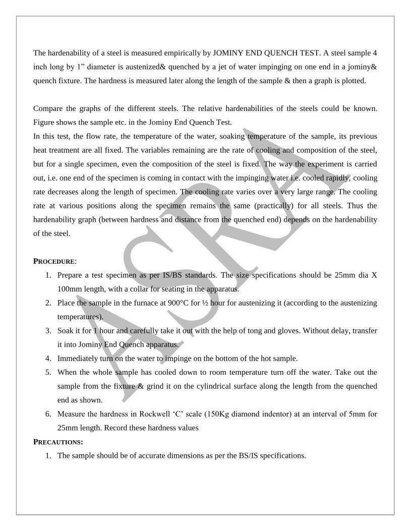
The hardenability of a steel is measured empirically by JOMINY END QUENCH TEST. A steel sample 4
inch long by 1” diameter is austenized& quenched by a jet of water impinging on one end in a jominy&
quench fixture. The hardness is measured later along the length of the sample & then a graph is plotted.
Compare the graphs of the different steels. The relative hardenabilities of the steels could be known.
Figure shows the sample etc. in the Jominy End Quench Test.
In this test, the flow rate, the temperature of the water, soaking temperature of the sample, its previous
heat treatment are all fixed. The variables remaining are the rate of cooling and composition of the steel,
but for a single specimen, even the composition of the steel is fixed. The way the experiment is carried
out, i.e. one end of the specimen is coming in contact with the impinging water i.e. cooled rapidly, cooling
rate decreases along the length of specimen. The cooling rate varies over a very large range. The cooling
rate at various positions along the specimen remains the same (practically) for all steels. Thus the
hardenability graph (between hardness and distance from the quenched end) depends on the hardenability
of the steel.
PROCEDURE:
1. Prepare a test specimen as per IS/BS standards. The size specifications should be 25mm dia X
100mm length, with a collar for seating in the apparatus.
2. Place the sample in the furnace at 900°C for ½ hour for austenizing it (according to the austenizing
temperatures).
3. Soak it for 1 hour and carefully take it out with the help of tong and gloves. Without delay, transfer
it into Jominy End Quench apparatus.
4. Immediately turn on the water to impinge on the bottom of the hot sample.
5. When the whole sample has cooled down to room temperature turn off the water. Take out the
sample from the fixture & grind it on the cylindrical surface along the length from the quenched
end as shown.
6. Measure the hardness in Rockwell „C‟ scale (150Kg diamond indentor) at an interval of 5mm for
25mm length. Record these hardness values
PRECAUTIONS:
1. The sample should be of accurate dimensions as per the BS/IS specifications.
2. The furnace should be at appropriate distance from the Jominy test apparatus so that the specimen
could be transferred to the apparatus in minimum possible time.
3. Grinding should be carried out at low RPM to avoid any tempering for the hardened sample.
4. The Jominy Test apparatus is designed and manufactured as per IS and BS specifications, so do
not adjust any part of it.
5. Keep the apparatus dry when not in use by draining the water through the water outlet.
6. Use reasonably soft water as hard water may lead to formation of scales in nozzles and copper
conduits.
QUESTIONS FOR VIVA-VOCE:
a) What is the purpose of Collar in preparing specimen for Jominy end quench test?
b) What is the usefulness of performing Jominy end quench test?
c) What is Austenizing Temperature?
Keeping what points in mind, should the specimen be ground after quenching
BTME-308 Strength of Materials Lab
EXPERIMENT NO-1
AIM:To perform tensile test in ductile &brittle material & to draw stress-strain curve & to determine
various mechanical properties.
REQUIREMENTS:
1. Universal Testing Machine(UTM)
2. Test specimen
3. Micrometer
4. Steel scale
THEORY: A tensile force is one which alongates a member. When a metal piece is loaded by tensile force,
metal piece (Test sample) gets a tensile strain. Tensile test consists in straining a test piece by tensile
stress, generally to fracture, with a view of determining one or more of the continuously properties. This
test is done on UTM.
UTM
A UTM consists of:
1. Loading Unit
2. Control Unit
1. Loading Unit: This unit consists of two cross heads and one lower table. Upper & Lower table are
rigidly connected to columns operated by hydraulically operated piston . Lower crosshead can be moved
up and down by rotating to screwed columns by chain and sprocket drive of the motor mounted in the base
of this unit. Specimen is fixed between two cross heads and table according to tensile or compression test.
For tensile test the specimen is fixed between lower crosshead and upper crosshead. For the compression
test the specimen is inserted rotating the four handles each provided in the upper cross head and lower
crosshead.
2. Control Unit: This is to measure continuously the load being applied to the teat piece. This unit
incorporates switches and push buttons to operate motors of pump as well as vertical screwed columns.
The hydraulic cylinder of the loading unit is connected through pipe and operated by a high pressure pump
driven by a electric motor fitted in this control unit. For measuring the magnitude of force on the test piece
the cylinder is connected by pressure pipe to the between the lower table and lower cross head. The tensile
test piece is fixed in the rack jaws by control unit were a pendulum dynamometer operates the pointer of
measuring gauge through rack and pinion arrangement.
PROCEDURE:
1. The diameter of the test piece is measured by means of a micrometer at least at three plane and
determine the mean value. The gauge length is marked.
2. Suitable scale is selected.
3. The test specimen in the grips is inserted by adjusting the cross-heads of the machine.
4. Fix the extensometer on the test piece and set its scale dials to zero position.
5. Graph recording system is activated.
6. Machine is started and readings of dials on the extensometer is taken for a particular value of
load.
7. The rate of loading may be 10 mpc/sec initially and should be reduced to 7.5mpc/sec. when the
yield point is reached.
8. Load is applied continuously till the specimen breaks and then stop the machine.
9. Plot load vs extension diagram.
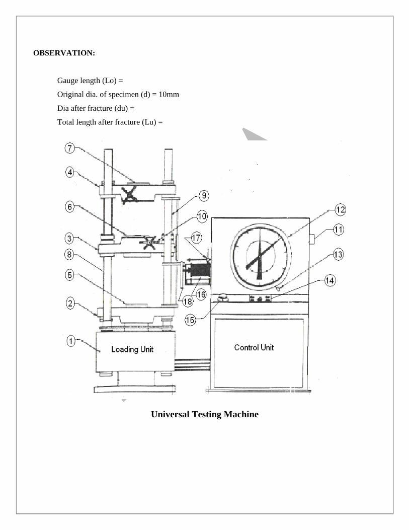
OBSERVATION:
Gauge length (Lo) =
Original dia. of specimen (d) = 10mm
Dia after fracture (du) =
Total length after fracture (Lu) =
Universal Testing Machine
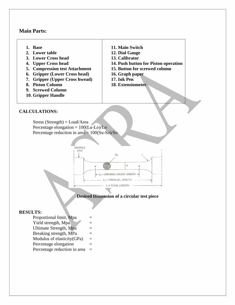
Main Parts:
1. Base
2. Lower table
3. Lower Cross head
4. Upper Cross head
5. Compression test Attachment
6. Gripper (Lower Cross head)
7. Gripper (Upper Cross hwead)
8. Piston Column
9. Screwed Column
10. Gripper Handle
11. Main Switch
12. Dial Gauge
13. Calibrator
14. Push button for Piston operation
15. Button for screwed column
16. Graph paper
17. Ink Pen
18. Extensiometer
CALCULATIONS:
Stress (Strength) = Load/Area
Percentage elongation = 100(Lu-Lo)/Lo
Percentage reduction in area = 100(Su-So)/So
Desired Dimension of a circular test piece
RESULTS:
Proportional limit, Mpa =
Yield strength, Mpa =
Ultimate Strength, Mpa =
Breaking strength, MPa =
Modulus of elasticity(GPa) =
Percentage elongation =
Percentage reduction in area =
Experiment No-2
AIM: To perform Compression test on C.I. & to determine ultiamate compressive strength.
REQUIREMENTS:
1. Universal Testing Machine
2. Test piece
THEORY:
Compression Test consists in straining a test piece by compression loading. Specimen for
compression test on metal are usually circular, and for concrete square, in-section. To prevent failure by
bulking, the length should be of about the same order as the minimum width. In the ductile material
distortion takes place while in case of brittle materials, usually fail by shearing.
PROCEDURE:
1. Measure the diameter of the test piece at three different planes and take the average value.
2. Place the specimen between middle and lower cross heads and apply the compressive load.
3. Increase the load gradually until the specimen fails.
OBSERVATIONS:
Ultimate load =
Average diameter of test piece (D) =
CALCULATIONS:
Cross-sectional area =
Ultimate compressive strength =
PRECAUTIONS:
1. 1. The specimen should be straight and ends of specimen must be at right angle to the axis of
specimen.
2. The length of specimen has to be kept small to avoid the buckling of the specimen.
RESULT:
Ultimate Compressive Strength =
Experiment No-3
AIM:To find out Rockwell Hardness Number of given test piece.
REQUIREMENTS:
1. Rockwell Hardness Tester
2. Test Piece
3. 1/16” Ball and Diamond Indentor
4. Microscope
THEORY:
Hardness represents the resistance of a material to indentation, and involves the measurement of plastic
deformation caused when a loaded ball or diamond is applied to the surface of material.
Rockwell Method: In this a hardened steel ball is pressed into the surface under a specified load which is
held on for a fixed period and then released.
PROCEDURE:
1. Place the test specimen and the test table of the testing machine.
2. Apply load slowly and progressively to the specimen at right angle to the surface and maintain full load
for 15 seconds.
3. When the dial indicator reached a stable position and the handle has reached the end forward position,
the applied load is taken off by pushing the loading handle to the rear position without jerk.The hardness
number is now indicated on the dial at the appropriate scale.
OBSERVATIONS:
Material of test piece =
Diameter of ball =
Load 'F' =
Load application time =
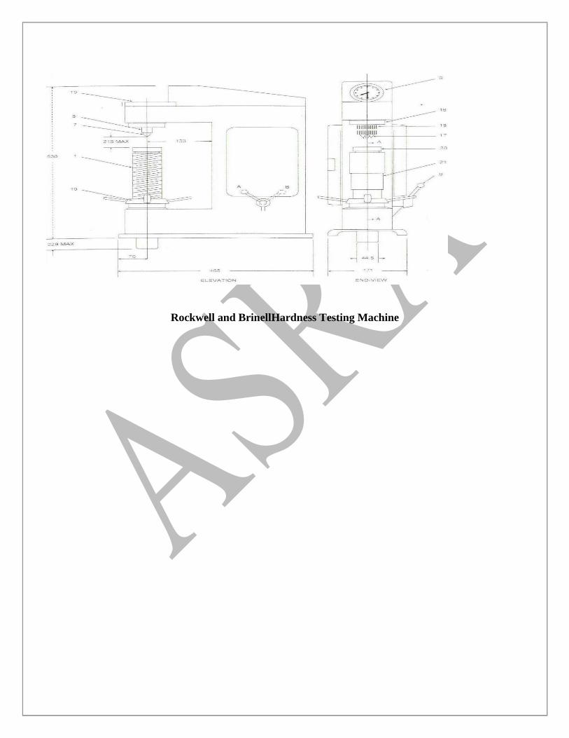
Rockwell and BrinellHardness Testing Machine
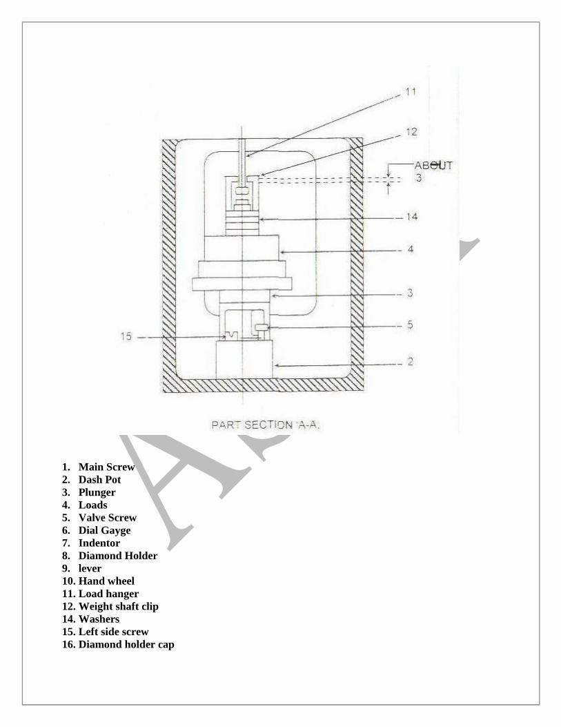
1. Main Screw
2. Dash Pot
3. Plunger
4. Loads
5. Valve Screw
6. Dial Gayge
7. Indentor
8. Diamond Holder
9. lever
10. Hand wheel
11. Load hanger
12. Weight shaft clip
14. Washers
15. Left side screw
16. Diamond holder cap
17. Clamping cone
18. Clamping check nut
19. Top plate
20. Test table
21. Telescope cover
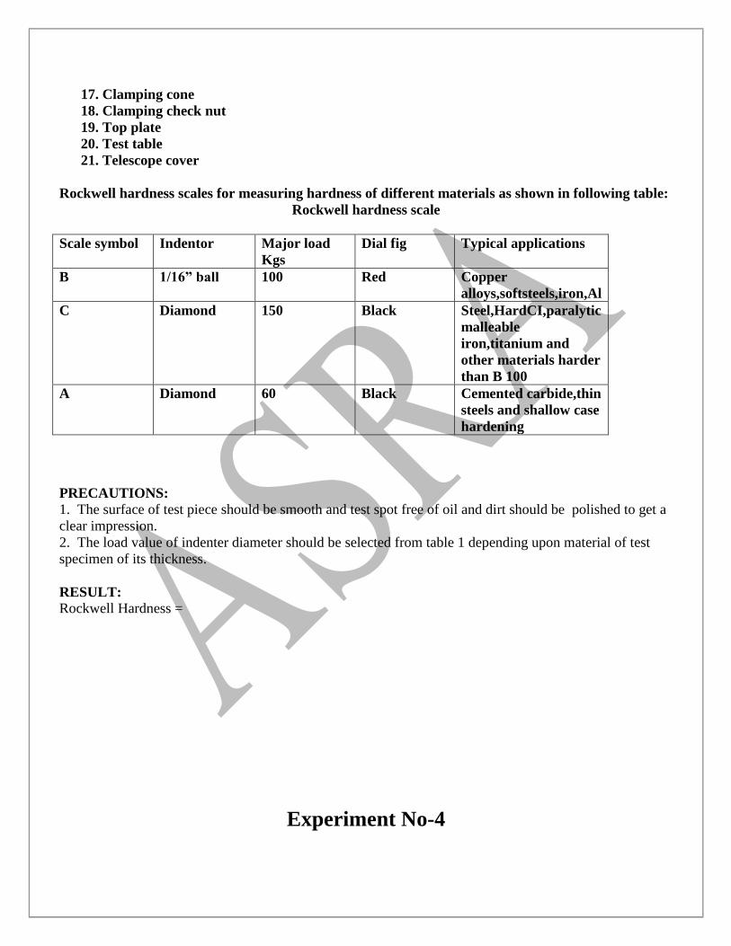
Rockwell hardness scales for measuring hardness of different materials as shown in following table:
Rockwell hardness scale
Scale symbol Indentor Major load
Kgs
Dial fig Typical applications
B 1/16” ball 100 Red Copper
alloys,softsteels,iron,Al
C Diamond 150 Black Steel,HardCI,paralytic
malleable
iron,titanium and
other materials harder
than B 100
A Diamond 60 Black Cemented carbide,thin
steels and shallow case
hardening
PRECAUTIONS:
1. The surface of test piece should be smooth and test spot free of oil and dirt should be polished to get a
clear impression.
2. The load value of indenter diameter should be selected from table 1 depending upon material of test
specimen of its thickness.
RESULT:
Rockwell Hardness =
Experiment No-4
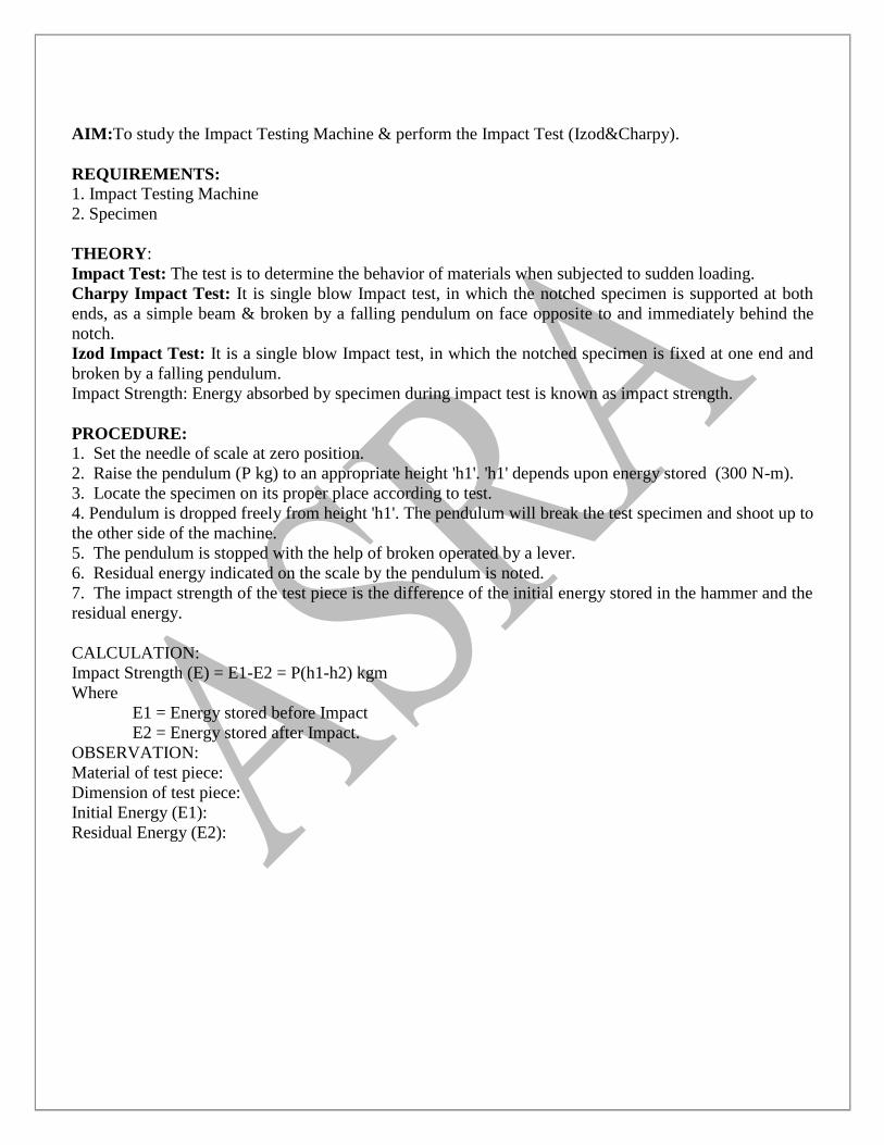
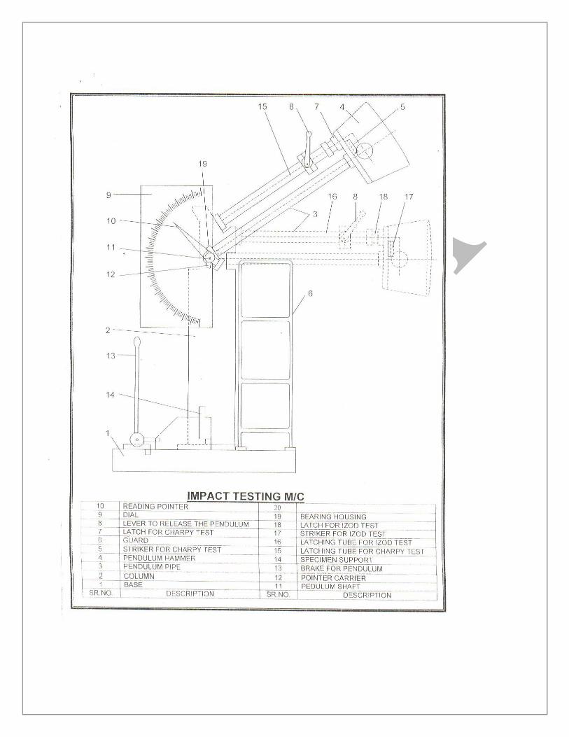
AIM:To study the Impact Testing Machine & perform the Impact Test (Izod&Charpy).
REQUIREMENTS:
1. Impact Testing Machine
2. Specimen
THEORY:
Impact Test: The test is to determine the behavior of materials when subjected to sudden loading.
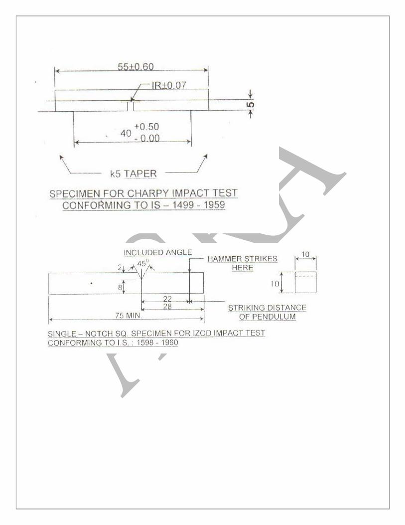
Charpy Impact Test: It is single blow Impact test, in which the notched specimen is supported at both
ends, as a simple beam & broken by a falling pendulum on face opposite to and immediately behind the
notch.
Izod Impact Test: It is a single blow Impact test, in which the notched specimen is fixed at one end and
broken by a falling pendulum.
Impact Strength: Energy absorbed by specimen during impact test is known as impact strength.
PROCEDURE:
1. Set the needle of scale at zero position.
2. Raise the pendulum (P kg) to an appropriate height 'h1'. 'h1' depends upon energy stored (300 N-m).
3. Locate the specimen on its proper place according to test.
4. Pendulum is dropped freely from height 'h1'. The pendulum will break the test specimen and shoot up to
the other side of the machine.
5. The pendulum is stopped with the help of broken operated by a lever.
6. Residual energy indicated on the scale by the pendulum is noted.
7. The impact strength of the test piece is the difference of the initial energy stored in the hammer and the
residual energy.
CALCULATION:
Impact Strength (E) = E1-E2 = P(h1-h2) kgm
Where
E1 = Energy stored before Impact
E2 = Energy stored after Impact.
OBSERVATION:
Material of test piece:
Dimension of test piece:
Initial Energy (E1):
Residual Energy (E2):
PRECAUTIONS:
1. One should not stand in the swinging line of pendulum.
2. Hammer should be in 'locking' position when the specimen is being placed for testing.
3. Keep the machine in locking position after the practical is over.
RESULT:
Impact Strength of specimen = --------kgm
Experiment No-5
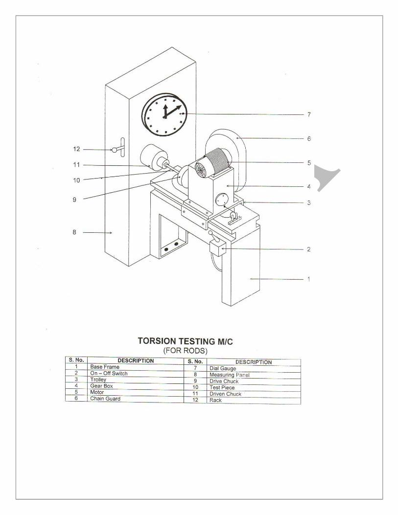
AIM: To study the Torsion Testing Machine & perform torsion test.
REQUIREMENTS:
1. Torsion Testing Machine
2. Specimen
3. Micrometer
4. Steel Scale
THEORY: A circular cylindrical shaft is said to be subjected to pure torsion when the torsion is
caused by a couple, so that the axis of the applied couple coincides with the axis of the shaft. In such a
case the state of stress at any point in the cross-section of the shaft is pure shear.
Torsional formula is given by:
T/J = t/r =Gθ/L
Where,
T= Twisting Moment
J= Poller M.O.I. of original cross-section
t= Shear Stress induced in specimen
r= Radius of original cross-section
G= Modulus of Rigidity
θ= Angle of Twist
L= Perallel length of initial specimen
PROCEDURE:
1. Measure the diameter of the test piece of four different planes on its parallel length by using a
Micrometer. At each plane measure the diameter at right angle to each other.
2. Measure the parallel length of the test piece.
3. Insert the test piece in the grips of the machine.
4. Select a suitable scale on the digital indicator and adjust the initial torque and angle of twist reading to
zero position.
5. Apply the torque on specimen with the driving chuck. To activate the driving chuck,switch on the.
Electrical lever control, with this, the test specimen start twisting and with the increased load, the digital
display on the digital indicator unit progressed
6. Torque is applied untill specimen breaks and maximum torque that sample has taken is read out from
Digital Indicator unit by pressing the PEAK push button.
7. Angle of twist is noted from Angle of twist measuring wheel after the specimen has failed.
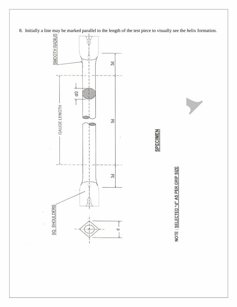
8. Initially a line may be marked parallel to the length of the test piece to visually see the helix formation.
OBSERVATIONS:-
1. Material of test specimen=
2. Least count of micrometer=
3. Parallel length of test specimen=
4. Diameter:
5. Maximum torque (N-m) =
6. Breaking torque (N-m) =
7. Angle of twist Ø =
CALCULATIONS:-
Modulus of rupture ts = Tr/J
Modulus of rigidity G = Tl/Jθ
Where:
T= Maximum twisting moment.
r= Original outer radius of specimen
J= Polar moment of inertia of the original cross-section
θ= Angle of twist
l= Parallel length of specimen.
RESULTS:-
1.Maximum torque=
2.Breaking torque=
3.Total angle of twist to fracture
4.Modulus of rupture=
5.Modulus of rigidity=
Experiment No-6
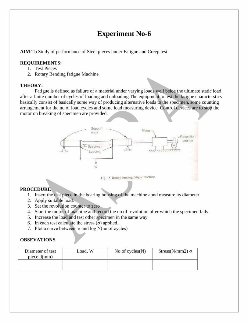
AIM:To Study of performance of Steel pieces under Fatigue and Creep test.
REQUIREMENTS:
1. Test Pieces
2. Rotary Bending fatigue Machine
THEORY:
Fatigue is defined as failure of a material under varying loads well beloe the ultimate static load
after a finite number of cycles of loading and unloading.The equipment to test the fatigue characterstics
basically consist of basically some way of producing alternative loads to the specimen, some counting
arrangement for the no of load cycles and some load measuring device. Control devices are to stop the
motor on breaking of specimen are provided.
PROCEDURE
1. Insert the test piece in the bearing housing of the machine abnd measure its diameter.
2. Apply suitable load.
3. Set the revolution counter to zero
4. Start the motor of machine and record the no of revolution after which the specimen fails
5. Increase the load and test other specimen in the same way
6. In each test calculate the stress (σ) applied.
7. Plot a curve between σ and log N(no of cycles)
OBSEVATIONS
Diameter of test
piece d(mm)
Load, W No of cycles(N) Stress(N/mm2) σ
Experiment No-7
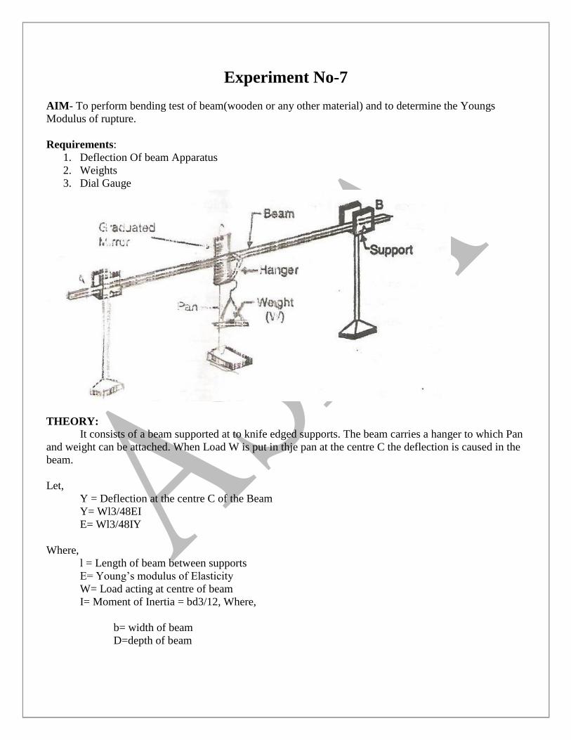
AIM- To perform bending test of beam(wooden or any other material) and to determine the Youngs
Modulus of rupture.
Requirements:
1. Deflection Of beam Apparatus
2. Weights
3. Dial Gauge
THEORY:
It consists of a beam supported at to knife edged supports. The beam carries a hanger to which Pan
and weight can be attached. When Load W is put in thje pan at the centre C the deflection is caused in the
beam.
Let,
Y = Deflection at the centre C of the Beam
Y= Wl3/48EI
E= Wl3/48IY
Where,
l = Length of beam between supports
E= Young‟s modulus of Elasticity
W= Load acting at centre of beam
I= Moment of Inertia = bd3/12, Where,
b= width of beam
D=depth of beam
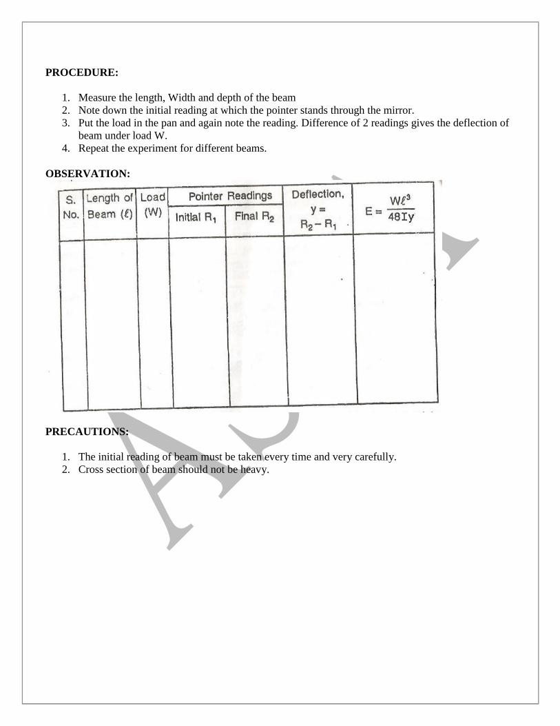
PROCEDURE:
1. Measure the length, Width and depth of the beam
2. Note down the initial reading at which the pointer stands through the mirror.
3. Put the load in the pan and again note the reading. Difference of 2 readings gives the deflection of
beam under load W.
4. Repeat the experiment for different beams.
OBSERVATION:
PRECAUTIONS:
1. The initial reading of beam must be taken every time and very carefully.
2. Cross section of beam should not be heavy.
Experiment No-9
AIM: -To perform torsion test on closed coil helical spring in tension and compression and to determine
stiffness of springs.
APPARATUS: - Spring testing machine, helical springs, micrometer, weights etc.
Description of the apparatus: Spring testing machine consists of a rectangular of metal frame
with channel sections along both the vertical sides. It is provided with holes in each corner for fixing the
apparatus by means of bolts embedded in the vertical support. The nuts are screwed tightly on the bolts.
On the vertical side of the channel, a scale (S) marked in cm and mm is provided to measure the
extensions ( or compression) caused the applied load.
Between the side channels, a movable frame with vernier (V) marked units-10, attached with a rod,
moves freely when load is applied at the bottom hook (C). There is a hook (B) on the top of this movable
frame.
Another frame at the top is fixed with the channel sections of the metal frame. The top frame has a
horizontal top head with a screw at top and a hook (A) in the centre, below the top head.
When tensile loads are applied at bottom hook (C), the spring is attached between the hooks A &
B.
PROCEDURE: -
1 Put both the springs on the hooks provided
2 Note down the initial reading before the application of load or adjust the initial reading to read
0-0.
3 Apply a load W1 on the springs which causes an extension in the tension spring and
compression in the compression spring. Note down the reading on the scale to measure the
extension (δ1) in mm. Increase the loads gradually from W2, W3, W4, and so on.... Within the
elastic limit and record the extension δ2, δ3, δ4,.....
Plot the graph between load and extension ( deflection).
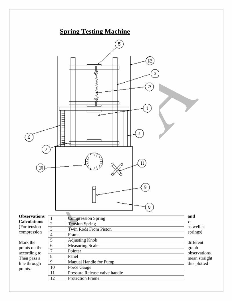
Spring Testing Machine
Observations and
Calculations :-
(For tension as well as
compression springs)
Mark the different
points on the graph
according to observations.
Then pass a mean straight
line through this plotted
points.
1 Compression Spring
2 Tension Spring
3 Twin Rods From Piston
4 Frame
5 Adjusting Knob
6 Measuring Scale
7 Pointer
8 Panel
9 Manual Handle for Pump
10 Force Gauge
11 Pressure Release valve handle
12 Protection Frame
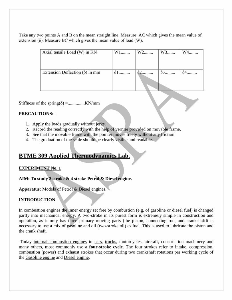
Take any two points A and B on the mean straight line. Measure AC which gives the mean value of
extension (δ). Measure BC which gives the mean value of load (W).
Stiffness of the spring(δ) =...............KN/mm
PRECAUTIONS: -
1. Apply the loads gradually without jerks.
2. Record the reading correctly with the help of vernier provided on movable frame.
3. See that the movable frame with the pointer moves freely without any friction.
4. The graduation of the scale should be clearly visible and readable.
BTME 309 Applied Thermodynamics Lab.
EXPERIMENT No. 1
AIM: To study 2 stroke & 4 stroke Petrol & Diesel engine.
Apparatus: Models of Petrol & Diesel engines.
INTRODUCTION
In combustion engines the inner energy set free by combustion (e.g. of gasoline or diesel fuel) is changed
partly into mechanical energy. A two-stroke in its purest form is extremely simple in construction and
operation, as it only has three primary moving parts (the piston, connecting rod, and crankshaftIt is
necessary to use a mix of gasoline and oil (two-stroke oil) as fuel. This is used to lubricate the piston and
the crank shaft.
Today internal combustion engines in cars, trucks, motorcycles, aircraft, construction machinery and
many others, most commonly use a four-stroke cycle. The four strokes refer to intake, compression,
combustion (power) and exhaust strokes that occur during two crankshaft rotations per working cycle of
the Gasoline engine and Diesel engine.
Axial tensile Load (W) in KN W1........ W2........ W3....... W4........
Extension Deflection (δ) in mm δ1.......... δ2.......... δ3......... δ4.........
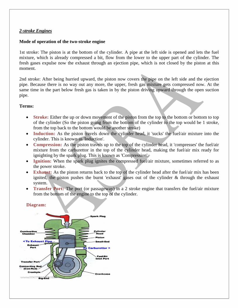
2-stroke Engines
Mode of operation of the two-stroke engine
1st stroke: The piston is at the bottom of the cylinder. A pipe at the left side is opened and lets the fuel
mixture, which is already compressed a bit, flow from the lower to the upper part of the cylinder. The
fresh gases expulse now the exhaust through an ejection pipe, which is not closed by the piston at this
moment.
2nd stroke: After being hurried upward, the piston now covers the pipe on the left side and the ejection
pipe. Because there is no way out any more, the upper, fresh gas mixture gets compressed now. At the
same time in the part below fresh gas is taken in by the piston driving upward through the open suction
pipe.
Terms:
Stroke: Either the up or down movement of the piston from the top to the bottom or bottom to top
of the cylinder (So the piston going from the bottom of the cylinder to the top would be 1 stroke,
from the top back to the bottom would be another stroke)
Induction: As the piston travels down the cylinder head, it 'sucks' the fuel/air mixture into the
cylinder. This is known as 'Induction'.
Compression: As the piston travels up to the top of the cylinder head, it 'compresses' the fuel/air
mixture from the carburettor in the top of the cylinder head, making the fuel/air mix ready for
ignighting by the spark plug. This is known as 'Compression'.
Ignition: When the spark plug ignites the compressed fuel/air mixture, sometimes referred to as
the power stroke.
Exhaust: As the piston returns back to the top of the cylinder head after the fuel/air mix has been
ignited, the piston pushes the burnt 'exhaust' gases out of the cylinder & through the exhaust
system.
Transfer Port: The port (or passageway) in a 2 stroke engine that transfers the fuel/air mixture
from the bottom of the engine to the top of the cylinder.
Diagram:
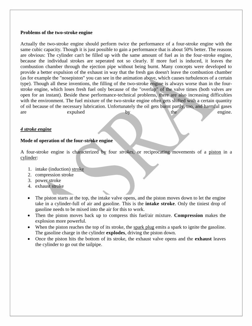
Problems of the two-stroke engine
Actually the two-stroke engine should perform twice the performance of a four-stroke engine with the
same cubic capacity. Though it is just possible to gain a performance that is about 50% better. The reasons
are obvious: The cylinder can't be filled up with the same amount of fuel as in the four-stroke engine,
because the individual strokes are seperated not so clearly. If more fuel is induced, it leaves the
combustion chamber through the ejection pipe without being burnt. Many concepts were developed to
provide a better expulsion of the exhaust in way that the fresh gas doesn't leave the combustion chamber
(as for example the "nosepiston" you can see in the animation above, which causes turbulences of a certain
type). Though all these inventions, the filling of the two-stroke engine is always worse than in the four-
stroke engine, which loses fresh fuel only because of the "overlap" of the valve times (both valves are
open for an instant). Beside these performance-technical problems, there are also increasing difficulties
with the environment. The fuel mixture of the two-stroke engine often gets shifted with a certain quantity
of oil because of the necessary lubrication. Unfortunately the oil gets burnt partly, too, and harmful gases
are expulsed by the engine.
4 stroke engine
Mode of operation of the four-stroke engine
A four-stroke engine is characterized by four strokes, or reciprocating movements of a piston in a
cylinder:
1. intake (induction) stroke
2. compression stroke
3. power stroke
4. exhaust stroke
The piston starts at the top, the intake valve opens, and the piston moves down to let the engine
take in a cylinder-full of air and gasoline. This is the intake stroke. Only the tiniest drop of
gasoline needs to be mixed into the air for this to work.
Then the piston moves back up to compress this fuel/air mixture. Compression makes the
explosion more powerful.
When the piston reaches the top of its stroke, the spark plug emits a spark to ignite the gasoline.
The gasoline charge in the cylinder explodes, driving the piston down.
Once the piston hits the bottom of its stroke, the exhaust valve opens and the exhaust leaves
the cylinder to go out the tailpipe.
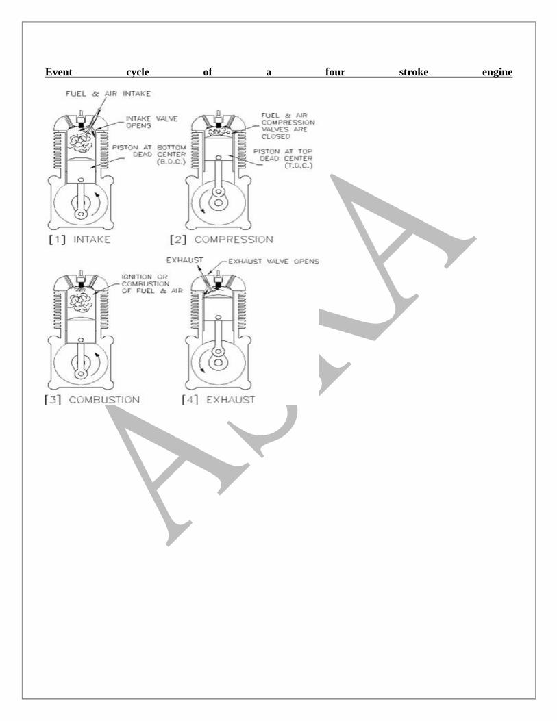
Event cycle of a four stroke engine
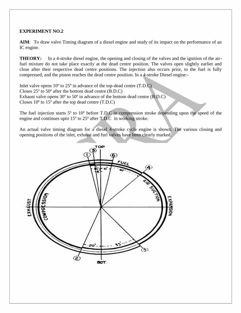
EXPERIMENT NO.2
AIM: To draw valve Timing diagram of a diesel engine and study of its impact on the performance of an
IC engine.
THEORY: In a 4-stroke diesel engine, the opening and closing of the valves and the ignition of the air-
fuel mixture do not take place exactly at the dead centre position. The valves open slightly earlier and
close after their respective dead centre positions. The injection also occurs prior, to the fuel is fully
compressed, and the piston reaches the dead centre position. In a 4-stroke Diesel engine:-
Inlet valve opens 10º to 25º in advance of the top-dead centre (T.D.C)
Closes 25º to 50º after the bottom dead centre (B.D.C)
Exhaust valve opens 30º to 50º in advance of the bottom dead centre (B.D.C)
Closes 10º to 15º after the top dead centre (T.D.C)
The fuel injection starts 5º to 10º before T.D.C in compression stroke depending upon the speed of the
engine and continues upto 15º to 25º after T.D.C in working stroke.
An actual valve timing diagram for a diesel 4-stroke cycle engine is shown. The various closing and
opening positions of the inlet, exhaust and furl valves have been clearly marked.
Combustion Phenomenon in Compression Ignition Engines.
In CI. Engines, the intake is air alone and the fuel is injected at high pressure in the form of droplets near
the end of compression. This lead to delay period: Each minute droplet of fuel as it enters the highly
heated air of engine cylinder is quickly surrounded by an envelope of vapours and this in turn and an
appreciable internal is inflamed at the surface of the envelope. To evaporate the liquid, latent heat is
abstracted from the surrounding air which reduces the temperature of a thin layer of air surrounding the
droplet and some time must elapse before this temperature can be raised again by abstracting heat from the
main bulk of air in its vicinity. As soon as this vapour and air in actual contact with it reach a certain
temperature, ignition will take place. Once ignition has started and a flame established the heat required
for further evaporation will be supplied from that released by combustion. The vapour would be burning
as fast as it can find fresh oxygen. If air within the cylinder were motionless only a small proportion of
fuel would find sufficient oxygen; for it is impossible to distribute the droplets uniformly throughout the
combustion space; some movement is absolutely essential, in C. I. engine, we call it air swirl and mean an
orderly movement of the whole body of air with or without some eddying so as to bring a continuous
supply of fresh air to each burning droplet.
Performance Analysis of Internal Combustion Engines; Spark Ignition Engine
The curve shown is the fuel consumption loop or „hook curve‟ which is the basic curve from the practical
point of view of a petrol engine. The throttle is kept full open, speed is kept constant and the Fuel-Air ratio
is varied. The solid line curve is plotted for percentage brake mean effective pressure versus specific fuel
combustion. This curve gives salient points A, B, C, D and E. It may be noted that point E corresponds to
an engine running with very lean mixture whose ignition lag is very large so as to cause missing and
explosions in the intake system usually called back firing. As the fuel-air ratio is improved, the specific
fuel consumption also improves till at point D, it is the most economic fuel consumption. Beyond this the
improvement in power developed, i.e. mean effective pressure is possible but at the cost of economy.
Point D corresponds to approximately a relative fuel-air ratio of 0.85. The relative fuel-air ratio may be
defined as,
FR = airratiolcorrectfueChemically
airratioActualfuel
Point C corresponds to FR=1. This point has no significance for actual engine performance. If the fuel-air
ratio is made richer the power developed increases till point B is reached. This point indicates maximum
power developed and occurs at FR=1.1 to 1.2. Earlier in chapter 21, it has been shown that taking variable
specific heat and dissociation into account the maximum temperature is obtained at fuel-air ratio of about
20% richer. Thus the indicated mean effective pressure will be maximum at 20% richer mixture. In fact
the graph of temperature versus fuel-air ratio follows the same pattern as the graph of indicated mean
effective pressure versus fuel air ratio. Beyond FR=1.2. i.e very rich mixtures, the ignition delays are again
very large and problems similar to very lean mixtures are encountered, and thus the power developed
drops as shown by point A.
The curve ABCDE is obtained by keeping spark timing unchanged. If the spark timing is adjusted to
optimum every time while conducting the test, the specific fuel consumption further improves over the
whole range as shown by broken line curve E‟D‟C‟.
If this hook curve is re-plotted on the base of fuel-air ratio the result obtained is very revealing as shown
in fig. The graph of mean effective pressure vs. fuel-air ratio has clearly similar curve as the graph of
temperature vs. furl-air discussed earlier in the text.
The indicator diagrams obtained, corresponding to points
The curve ABCDE is obtained by keeping spark timing unchanged. If the spark timing is adjusted to
optimum every time while conducting the test, the specific fuel consumption further improves over the
whole range as shown by broken line curve E‟D‟C‟.
If this hook curve is re-plotted on the base of fuel-air ratio the result obtained is very revealing as shown
in fig. The graph of mean effective pressure vs. fuel-air ratio has clearly similar curve as the graph of
temperature vs. fuel-air ratio discussed earlier in the text.
The indicator diagrams obtained corresponding to points B, D and E offer further explanation for very
large ignition delay for very lean mixtures as E, maximum power fuel-air ratio as B and maximum thermal
efficiency fuel-air ratio as D. The indicator diagrams are shown for three points in fig.
It has been proved that for the same compression ratio, Otto cycle is thermally more efficient than the
diesel cycle but the mean effective pressure for the diesel cycle is greater than that for the Otto cycle. To
generalize on this reasoning, it may be said that any factor which tends to increase the crank angle
occupied by combustion will tend to increase the fuel-air ratio for best economy. This is verified from the
indicator diagram shown in fig. The diagram D is very near to constant volume cycle whereas diagram B
which maximum power diagram has flat top and the diagram E shows very large ignition lag characteristic
of very lean mixtures which have very slow combustion rates.
The same points can be shown by indicator diagrams with crank angle base as shown in fig. This crank
angle for combustion for condition B is greater than for condition D. And for condition E, the ignition lag
is very large in terms of crank angles.
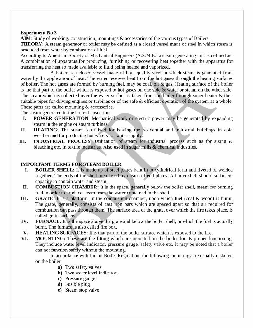
Experiment No 3
AIM: Study of working, construction, mountings & accessories of the various types of Boilers.
THEORY: A steam generator or boiler may be defined as a closed vessel made of steel in which steam is
produced from water by combustion of fuel.
According to American Society of Mechanical Engineers (A.S.M.E.) a steam generating unit is defined as:
A combination of apparatus for producing, furnishing or recovering heat together with the apparatus for
transferring the heat so made available to fluid being heated and vaporized.
A boiler is a closed vessel made of high quality steel in which steam is generated from
water by the application of heat. The water receives heat from the hot gases through the heating surfaces
of boiler. The hot gases are formed by burning fuel, may be coal, oil & gas. Heating surface of the boiler
is the that part of the boiler which is exposed to hot gases on one side & water or steam on the other side.
The steam which is collected over the water surface is taken from the boiler through super heater & then
suitable pipes for driving engines or turbines or of the safe & efficient operation of the system as a whole.
These parts are called mounting & accessories.
The steam generated in the boiler is used for:
I. POWER GENERATION: Mechanical work or electric power may be generated by expanding
steam in the engine or steam turbines.
II. HEATING: The steam is utilized for heating the residential and industrial buildings in cold
weather and for producing hot waters for water supply.
III. INDUSTRIAL PROCESS: Utilization of steam for industrial process such as for sizing &
bleaching etc. In textile industries. Also used in sugar mills & chemical industries.
IMPORTANT TERMS FOR STEAM BOILER
I. BOILER SHELL: It is made up of steel plates bent in to cylindrical form and riveted or welded
together. The ends of the shell are closed by means of end plates. A boiler shell should sufficient
capacity to contain water and steam.
II. COMBUSTION CHAMBER: It is the space, generally below the boiler shell, meant for burning
fuel in order to produce steam from the water contained in the shell.
III. GRATE: It is a platform, in the combustion chamber, upon which fuel (coal & wood) is burnt.
The grate, generally, consists of cast iron bars which are spaced apart so that air required for
combustion can pass through them. The surface area of the grate, over which the fire takes place, is
called grate surface.
IV. FURNACE: It is the space above the grate and below the boiler shell, in which the fuel is actually
burnt. The furnace is also called fire box.
V. HEATING SURFACES: It is that part of the boiler surface which is exposed to the fire.
VI. MOUNTING: These are the fitting which are mounted on the boiler for its proper functioning.
They include water level indicator, pressure gauge, safety valve etc. It may be noted that a boiler
can not function safely without the mounting.
In accordance with Indian Boiler Regulation, the following mountings are usually installed
on the boiler
a) Two safety valves
b) Two water level indicators
c) Pressure gauge
d) Fusible plug
e) Steam stop valve
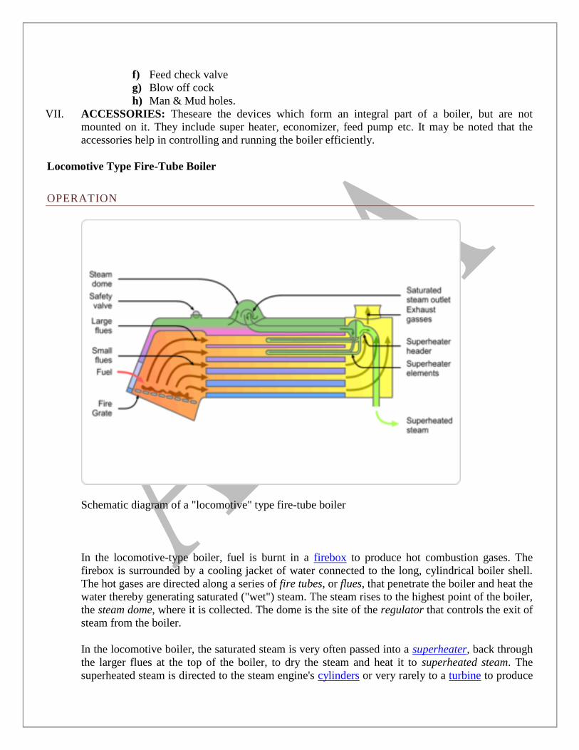
f) Feed check valve
g) Blow off cock
h) Man & Mud holes.
VII. ACCESSORIES: Theseare the devices which form an integral part of a boiler, but are not
mounted on it. They include super heater, economizer, feed pump etc. It may be noted that the
accessories help in controlling and running the boiler efficiently.
Locomotive Type Fire-Tube Boiler
OPERATION
Schematic diagram of a "locomotive" type fire-tube boiler
In the locomotive-type boiler, fuel is burnt in a firebox to produce hot combustion gases. The
firebox is surrounded by a cooling jacket of water connected to the long, cylindrical boiler shell.
The hot gases are directed along a series of fire tubes, or flues, that penetrate the boiler and heat the
water thereby generating saturated ("wet") steam. The steam rises to the highest point of the boiler,
the steam dome, where it is collected. The dome is the site of the regulator that controls the exit of
steam from the boiler.
In the locomotive boiler, the saturated steam is very often passed into a superheater, back through
the larger flues at the top of the boiler, to dry the steam and heat it to superheated steam. The
superheated steam is directed to the steam engine's cylinders or very rarely to a turbine to produce
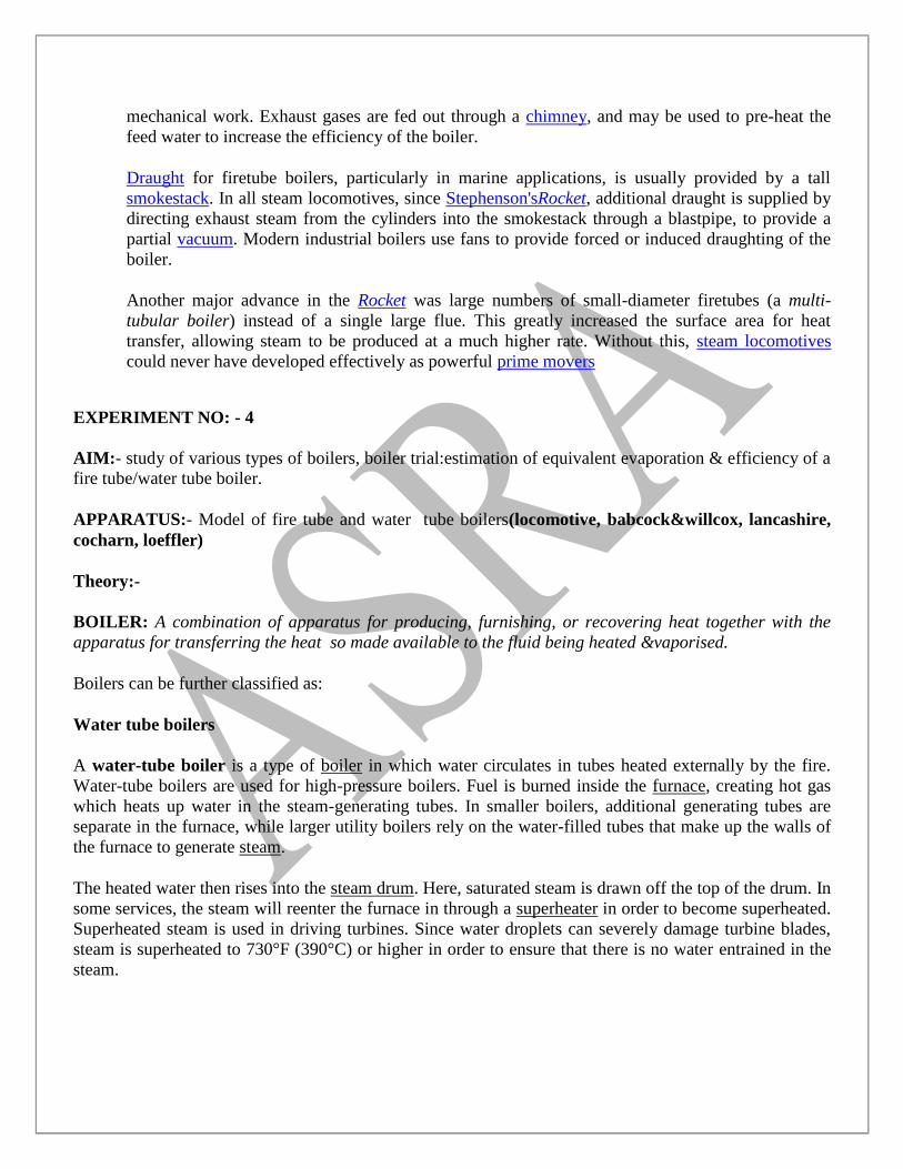
mechanical work. Exhaust gases are fed out through a chimney, and may be used to pre-heat the
feed water to increase the efficiency of the boiler.
Draught for firetube boilers, particularly in marine applications, is usually provided by a tall
smokestack. In all steam locomotives, since Stephenson'sRocket, additional draught is supplied by
directing exhaust steam from the cylinders into the smokestack through a blastpipe, to provide a
partial vacuum. Modern industrial boilers use fans to provide forced or induced draughting of the
boiler.
Another major advance in the Rocket was large numbers of small-diameter firetubes (a multi-
tubular boiler) instead of a single large flue. This greatly increased the surface area for heat
transfer, allowing steam to be produced at a much higher rate. Without this, steam locomotives
could never have developed effectively as powerful prime movers
EXPERIMENT NO: - 4
AIM:- study of various types of boilers, boiler trial:estimation of equivalent evaporation & efficiency of a
fire tube/water tube boiler.
APPARATUS:- Model of fire tube and water tube boilers(locomotive, babcock&willcox, lancashire,
cocharn, loeffler)
Theory:-
BOILER: A combination of apparatus for producing, furnishing, or recovering heat together with the
apparatus for transferring the heat so made available to the fluid being heated &vaporised.
Boilers can be further classified as:
Water tube boilers
A water-tube boiler is a type of boiler in which water circulates in tubes heated externally by the fire.
Water-tube boilers are used for high-pressure boilers. Fuel is burned inside the furnace, creating hot gas
which heats up water in the steam-generating tubes. In smaller boilers, additional generating tubes are
separate in the furnace, while larger utility boilers rely on the water-filled tubes that make up the walls of
the furnace to generate steam.
The heated water then rises into the steam drum. Here, saturated steam is drawn off the top of the drum. In
some services, the steam will reenter the furnace in through a superheater in order to become superheated.
Superheated steam is used in driving turbines. Since water droplets can severely damage turbine blades,
steam is superheated to 730°F (390°C) or higher in order to ensure that there is no water entrained in the
steam.
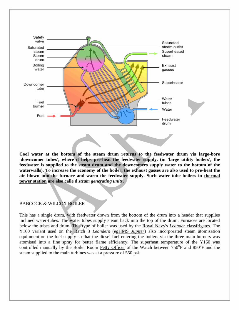
Cool water at the bottom of the steam drum returns to the feedwater drum via large-bore
'downcomer tubes', where it helps pre-heat the feedwater supply. (in 'large utility boilers', the
feedwater is supplied to the steam drum and the downcomers supply water to the bottom of the
waterwalls). To increase the economy of the boiler, the exhaust gasses are also used to pre-heat the
air blown into the furnace and warm the feedwater supply. Such water-tube boilers in thermal
power station are also calle d steam generating units.
BABCOCK & WILCOX BOILER
This has a single drum, with feedwater drawn from the bottom of the drum into a header that supplies
inclined water-tubes. The water tubes supply steam back into the top of the drum. Furnaces are located
below the tubes and drum. This type of boiler was used by the Royal Navy's Leander classfrigates. The
Y160 variant used on the Batch 3 Leanders (egHMS Jupiter) also incorporated steam atomisation
equipment on the fuel supply so that the diesel fuel entering the boilers via the three main burners was
atomised into a fine spray for better flame efficiency. The superheat temperature of the Y160 was
controlled manually by the Boiler Room Petty Officer of the Watch between 7500F and 850
0F and the
steam supplied to the main turbines was at a pressure of 550 psi.
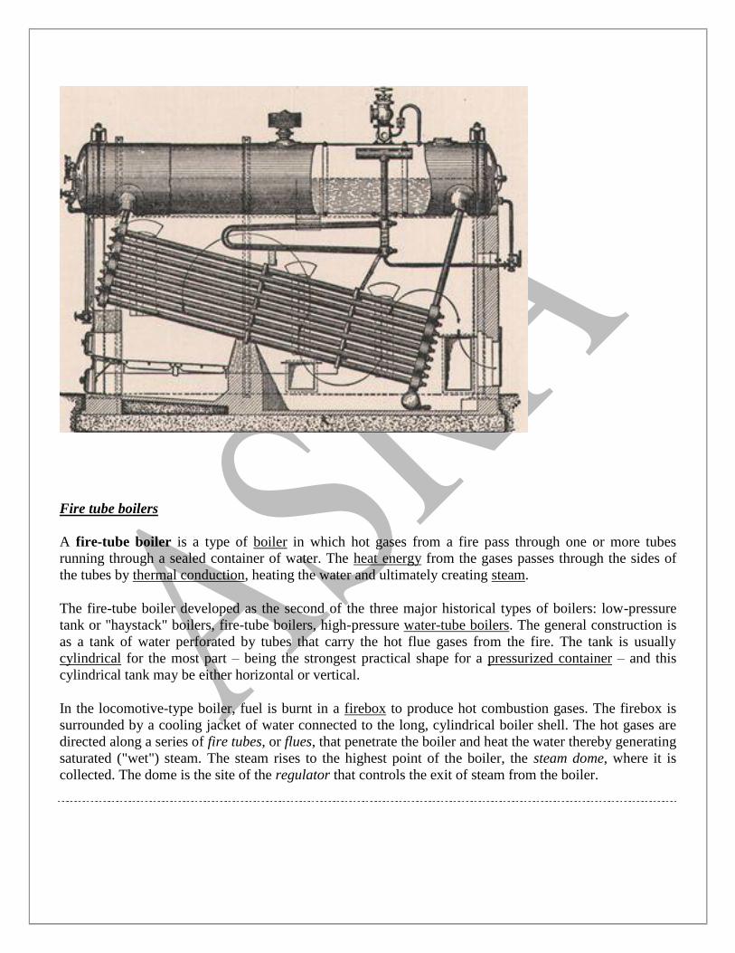
Fire tube boilers
A fire-tube boiler is a type of boiler in which hot gases from a fire pass through one or more tubes
running through a sealed container of water. The heat energy from the gases passes through the sides of
the tubes by thermal conduction, heating the water and ultimately creating steam.
The fire-tube boiler developed as the second of the three major historical types of boilers: low-pressure
tank or "haystack" boilers, fire-tube boilers, high-pressure water-tube boilers. The general construction is
as a tank of water perforated by tubes that carry the hot flue gases from the fire. The tank is usually
cylindrical for the most part – being the strongest practical shape for a pressurized container – and this
cylindrical tank may be either horizontal or vertical.
In the locomotive-type boiler, fuel is burnt in a firebox to produce hot combustion gases. The firebox is
surrounded by a cooling jacket of water connected to the long, cylindrical boiler shell. The hot gases are
directed along a series of fire tubes, or flues, that penetrate the boiler and heat the water thereby generating
saturated ("wet") steam. The steam rises to the highest point of the boiler, the steam dome, where it is
collected. The dome is the site of the regulator that controls the exit of steam from the boiler.
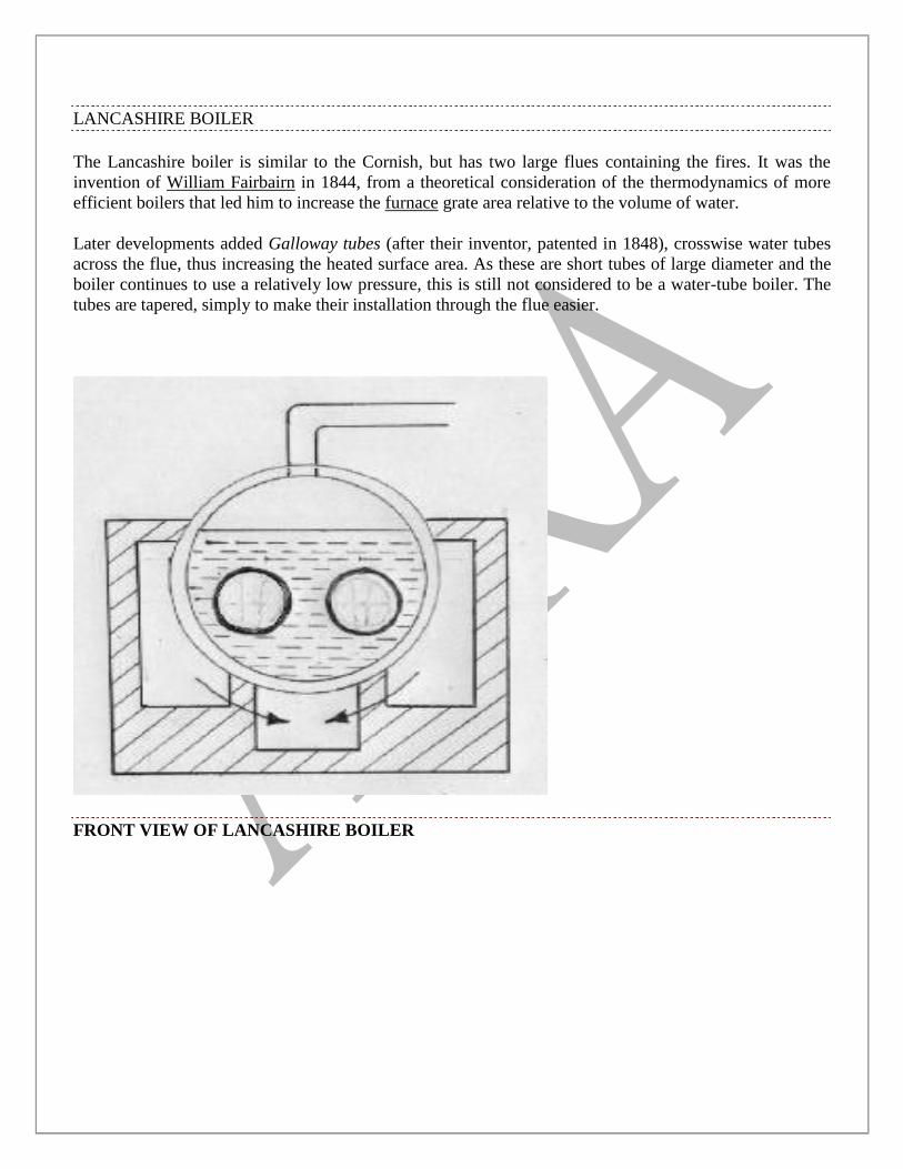
LANCASHIRE BOILER
The Lancashire boiler is similar to the Cornish, but has two large flues containing the fires. It was the
invention of William Fairbairn in 1844, from a theoretical consideration of the thermodynamics of more
efficient boilers that led him to increase the furnace grate area relative to the volume of water.
Later developments added Galloway tubes (after their inventor, patented in 1848), crosswise water tubes
across the flue, thus increasing the heated surface area. As these are short tubes of large diameter and the
boiler continues to use a relatively low pressure, this is still not considered to be a water-tube boiler. The
tubes are tapered, simply to make their installation through the flue easier.
FRONT VIEW OF LANCASHIRE BOILER
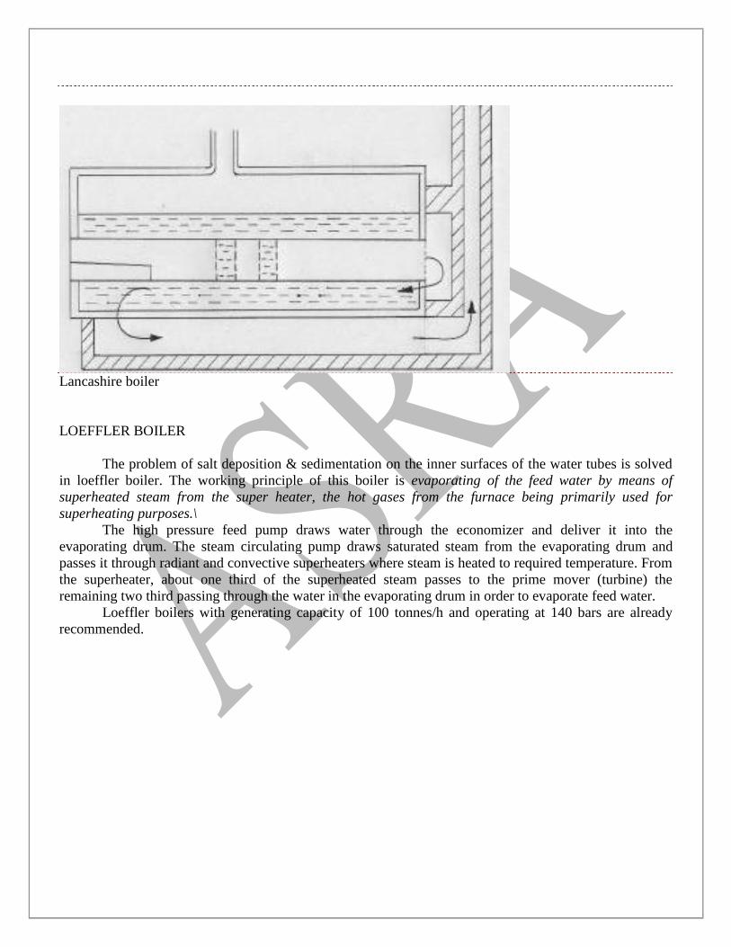
Lancashire boiler
LOEFFLER BOILER
The problem of salt deposition & sedimentation on the inner surfaces of the water tubes is solved
in loeffler boiler. The working principle of this boiler is evaporating of the feed water by means of
superheated steam from the super heater, the hot gases from the furnace being primarily used for
superheating purposes.\
The high pressure feed pump draws water through the economizer and deliver it into the
evaporating drum. The steam circulating pump draws saturated steam from the evaporating drum and
passes it through radiant and convective superheaters where steam is heated to required temperature. From
the superheater, about one third of the superheated steam passes to the prime mover (turbine) the
remaining two third passing through the water in the evaporating drum in order to evaporate feed water.
Loeffler boilers with generating capacity of 100 tonnes/h and operating at 140 bars are already
recommended.
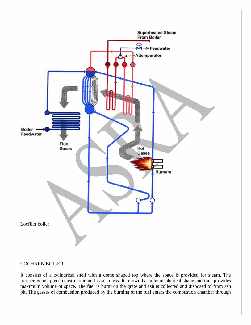
Loeffler boiler
COCHARN BOILER
It consists of a cylindrical shell with a dome shaped top where the space is provided for steam. The
furnace is one piece construction and is seamless. Its crown has a hemispherical shape and thus provides
maximum volume of space. The fuel is burnt on the grate and ash is collected and disposed of from ash
pit. The gasses of combustion produced by the burning of the fuel enters the combustion chamber through
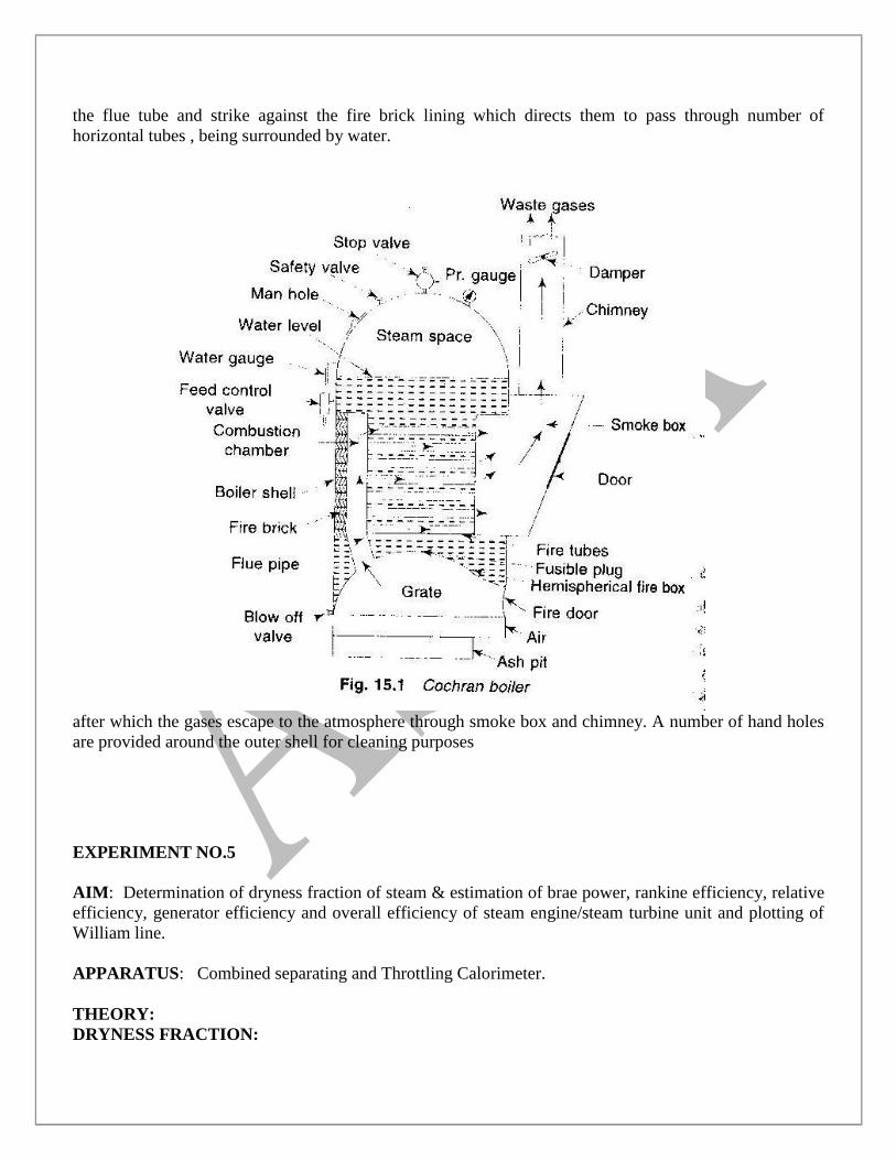
the flue tube and strike against the fire brick lining which directs them to pass through number of
horizontal tubes , being surrounded by water.
after which the gases escape to the atmosphere through smoke box and chimney. A number of hand holes
are provided around the outer shell for cleaning purposes
EXPERIMENT NO.5
AIM: Determination of dryness fraction of steam & estimation of brae power, rankine efficiency, relative
efficiency, generator efficiency and overall efficiency of steam engine/steam turbine unit and plotting of
William line.
APPARATUS: Combined separating and Throttling Calorimeter.
THEORY:
DRYNESS FRACTION:
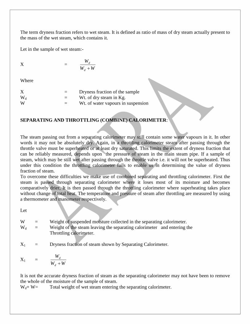
The term dryness fraction refers to wet steam. It is defined as ratio of mass of dry steam actually present to
the mass of the wet steam, which contains it.
Let in the sample of wet steam:-
X = WW
W
d
d
Where
X = Dryness fraction of the sample
Wd = Wt. of dry steam in Kg.
W = Wt. of water vapours in suspension
SEPARATING AND THROTTLING (COMBINE) CALORIMETER:
The steam passing out from a separating calorimeter may still contain some water vapours in it. In other
words it may not be absolutely dry. Again, in a throttling calorimeter steam after passing through the
throttle valve must be superheated or at least dry saturated. This limits the extent of dryness fraction that
can be reliably measured, depends upon the pressure of steam in the main steam pipe. If a sample of
steam, which may be still wet after passing through the throttle valve i.e. it will not be superheated. Thus
under this condition the throttling calorimeter fails to enable us in determining the value of dryness
fraction of steam.
To overcome these difficulties we make use of combined separating and throttling calorimeter. First the
steam is passed through separating calorimeter where it loses most of its moisture and becomes
comparatively drier, It is then passed through the throttling calorimeter where superheating takes place
without change of total heat. The temperature and pressure of steam after throttling are measured by using
a thermometer and manometer respectively.
Let
W = Weight of suspended moisture collected in the separating calorimeter.
Wd = Weight of the steam leaving the separating calorimeter and entering the
Throttling calorimeter.
X1 = Dryness fraction of steam shown by Separating Calorimeter.
X1 = WW
W
d
d
It is not the accurate dryness fraction of steam as the separating calorimeter may not have been to remove
the whole of the moisture of the sample of steam.
Wd+ W= Total weight of wet steam entering the separating calorimeter.
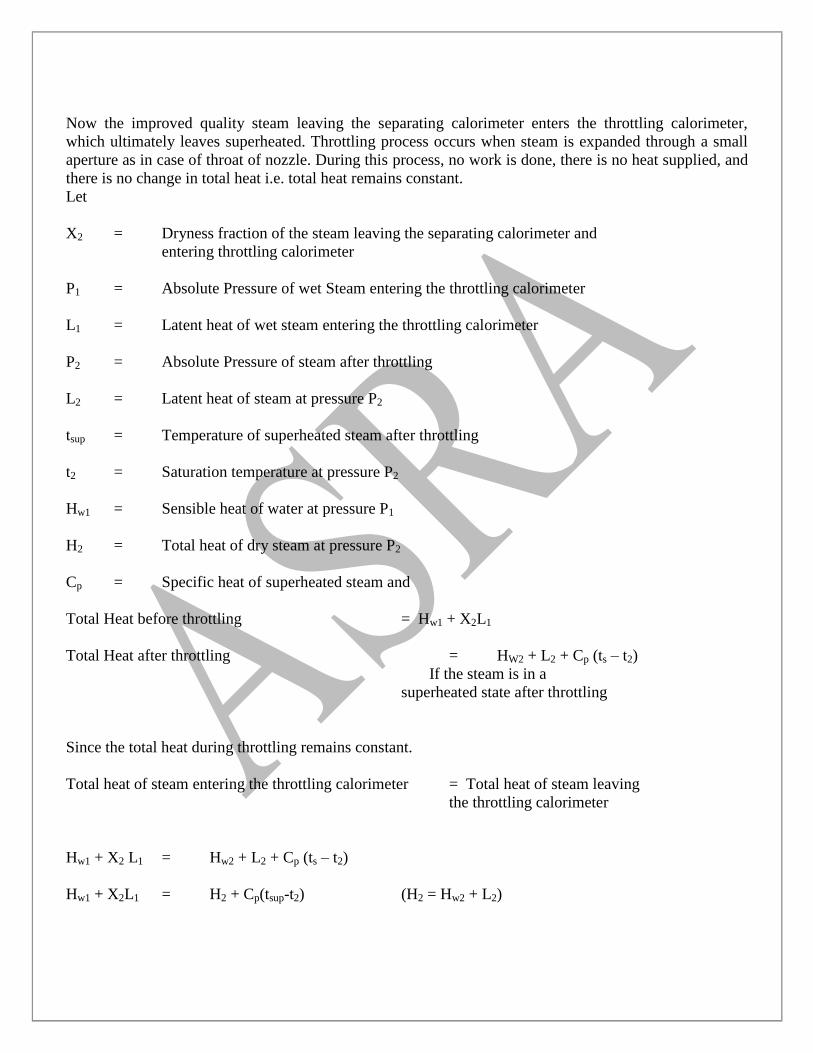
Now the improved quality steam leaving the separating calorimeter enters the throttling calorimeter,
which ultimately leaves superheated. Throttling process occurs when steam is expanded through a small
aperture as in case of throat of nozzle. During this process, no work is done, there is no heat supplied, and
there is no change in total heat i.e. total heat remains constant.
Let
X2 = Dryness fraction of the steam leaving the separating calorimeter and
entering throttling calorimeter
P1 = Absolute Pressure of wet Steam entering the throttling calorimeter
L1 = Latent heat of wet steam entering the throttling calorimeter
P2 = Absolute Pressure of steam after throttling
L2 = Latent heat of steam at pressure P2
tsup = Temperature of superheated steam after throttling
t2 = Saturation temperature at pressure P2
Hw1 = Sensible heat of water at pressure P1
H2 = Total heat of dry steam at pressure P2
Cp = Specific heat of superheated steam and
Total Heat before throttling = Hw1 + X2L1
Total Heat after throttling = HW2 + L2 + Cp (ts – t2)
If the steam is in a
superheated state after throttling
Since the total heat during throttling remains constant.
Total heat of steam entering the throttling calorimeter = Total heat of steam leaving
the throttling calorimeter
Hw1 + X2 L1 = Hw2 + L2 + Cp (ts – t2)
Hw1 + X2L1 = H2 + Cp(tsup-t2) (H2 = Hw2 + L2)
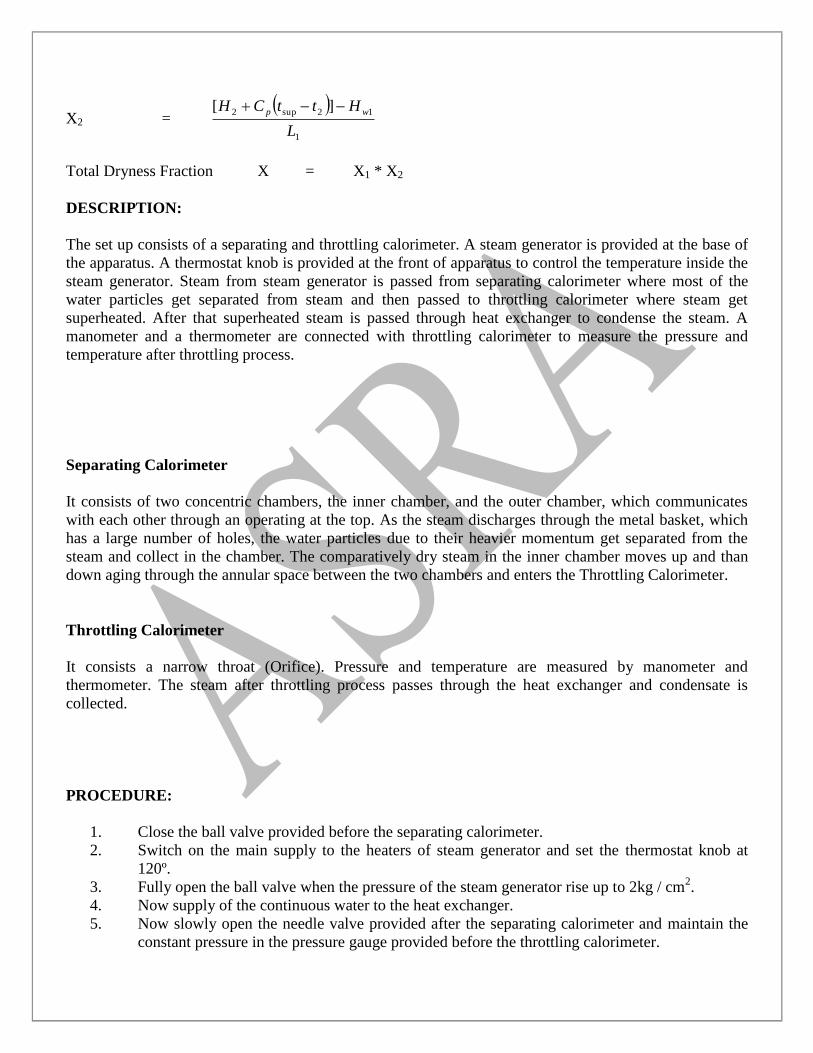
X2 =
1
12sup2 ][
L
HttCH wp
Total Dryness Fraction X = X1 * X2
DESCRIPTION:
The set up consists of a separating and throttling calorimeter. A steam generator is provided at the base of
the apparatus. A thermostat knob is provided at the front of apparatus to control the temperature inside the
steam generator. Steam from steam generator is passed from separating calorimeter where most of the
water particles get separated from steam and then passed to throttling calorimeter where steam get
superheated. After that superheated steam is passed through heat exchanger to condense the steam. A
manometer and a thermometer are connected with throttling calorimeter to measure the pressure and
temperature after throttling process.
Separating Calorimeter
It consists of two concentric chambers, the inner chamber, and the outer chamber, which communicates
with each other through an operating at the top. As the steam discharges through the metal basket, which
has a large number of holes, the water particles due to their heavier momentum get separated from the
steam and collect in the chamber. The comparatively dry steam in the inner chamber moves up and than
down aging through the annular space between the two chambers and enters the Throttling Calorimeter.
Throttling Calorimeter
It consists a narrow throat (Orifice). Pressure and temperature are measured by manometer and
thermometer. The steam after throttling process passes through the heat exchanger and condensate is
collected.
PROCEDURE:
1. Close the ball valve provided before the separating calorimeter.
2. Switch on the main supply to the heaters of steam generator and set the thermostat knob at
120º.
3. Fully open the ball valve when the pressure of the steam generator rise up to 2kg / cm2.
4. Now supply of the continuous water to the heat exchanger.
5. Now slowly open the needle valve provided after the separating calorimeter and maintain the
constant pressure in the pressure gauge provided before the throttling calorimeter.
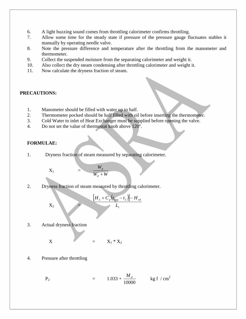
6. A light buzzing sound comes from throttling calorimeter confirms throttling.
7. Allow some time for the steady state if pressure of the pressure gauge fluctuates stables it
manually by operating needle valve.
8. Note the pressure difference and temperature after the throttling from the manometer and
thermometer.
9. Collect the suspended moisture from the separating calorimeter and weight it.
10. Also collect the dry steam condensing after throttling calorimeter and weight it.
11. Now calculate the dryness fraction of steam.
PRECAUTIONS:
1. Manometer should be filled with water up to half.
2. Thermometer pocked should be half filled with oil before inserting the thermometer.
3. Cold Water to inlet of Heat Exchanger must be supplied before opening the valve.
4. Do not set the value of thermostat knob above 120º.
FORMULAE:
1. Dryness fraction of steam measured by separating calorimeter.
X1 = WW
W
d
d
2. Dryness fraction of steam measured by throttling calorimeter.
X2 =
1
12sup2
L
HttCH wp
3. Actual dryness fraction
X = X1 * X2
4. Pressure after throttling
P2 = 1.033 + 10000
dM kg f / cm
2
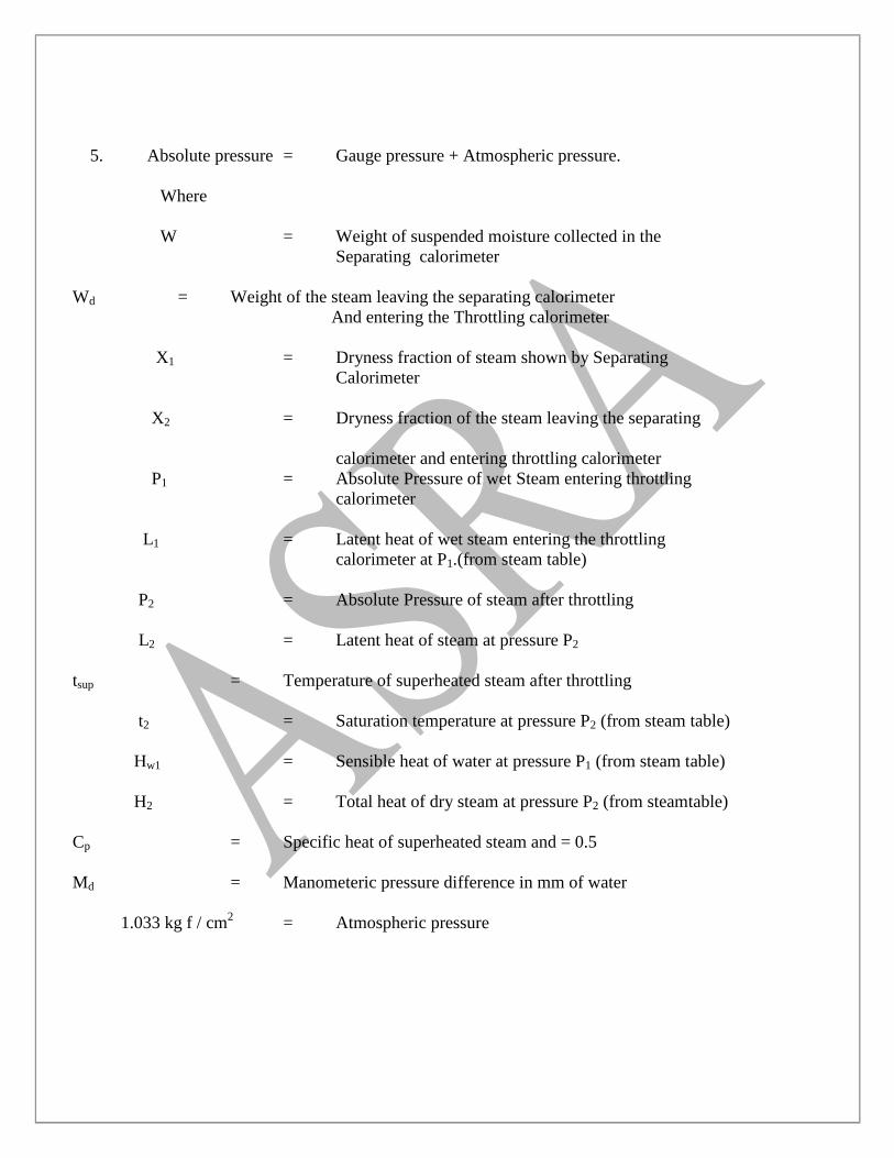
5. Absolute pressure = Gauge pressure + Atmospheric pressure.
Where
W = Weight of suspended moisture collected in the
Separating calorimeter
Wd = Weight of the steam leaving the separating calorimeter
And entering the Throttling calorimeter
X1 = Dryness fraction of steam shown by Separating
Calorimeter
X2 = Dryness fraction of the steam leaving the separating
calorimeter and entering throttling calorimeter
P1 = Absolute Pressure of wet Steam entering throttling
calorimeter
L1 = Latent heat of wet steam entering the throttling
calorimeter at P1.(from steam table)
P2 = Absolute Pressure of steam after throttling
L2 = Latent heat of steam at pressure P2
tsup = Temperature of superheated steam after throttling
t2 = Saturation temperature at pressure P2 (from steam table)
Hw1 = Sensible heat of water at pressure P1 (from steam table)
H2 = Total heat of dry steam at pressure P2 (from steamtable)
Cp = Specific heat of superheated steam and = 0.5
Md = Manometeric pressure difference in mm of water
1.033 kg f / cm2 = Atmospheric pressure

OBSERVATION TABLE:
S.NO Gauge Pressure
before throttling
Kg f / cm2
Temp. after
throttling,
Tsup º C
Manometer
difference,
Md (mm)
Weight of
moisture
collected, W
Weight of
dry steam,
Wd
CALCULATION TABLE:
S.NO. Absolute pressure
before throttling, P1
Kg f / cm2
Absolute
pressure
after
throttling, P2
Kg f / cm2
Dryness
fraction
from
separating
calorimeter,
X1
Dryness
fraction
from
throttling
calorimeter,
X2
Actual
dryness
fraction of
steam, X
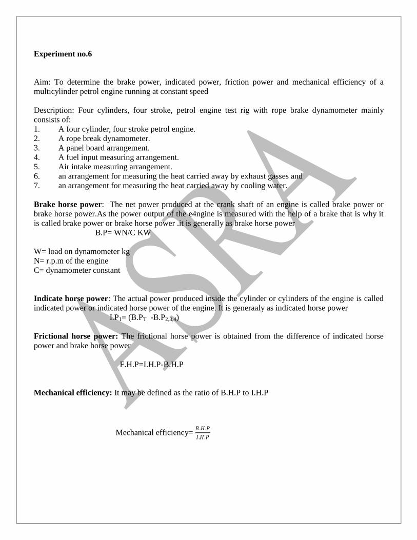
Experiment no.6
Aim: To determine the brake power, indicated power, friction power and mechanical efficiency of a
multicylinder petrol engine running at constant speed
Description: Four cylinders, four stroke, petrol engine test rig with rope brake dynamometer mainly
consists of:
1. A four cylinder, four stroke petrol engine.
2. A rope break dynamometer.
3. A panel board arrangement.
4. A fuel input measuring arrangement.
5. Air intake measuring arrangement.
6. an arrangement for measuring the heat carried away by exhaust gasses and
7. an arrangement for measuring the heat carried away by cooling water.
Brake horse power: The net power produced at the crank shaft of an engine is called brake power or
brake horse power.As the power output of the e4ngine is measured with the help of a brake that is why it
is called brake power or brake horse power .it is generally as brake horse power
B.P= WN/C KW
W= load on dynamometer kg
N= r.p.m of the engine
C= dynamometer constant
Indicate horse power: The actual power produced inside the cylinder or cylinders of the engine is called
indicated power or indicated horse power of the engine. It is generaaly as indicated horse power
I.P1= (B.PT -B.P2,3,4)
Frictional horse power: The frictional horse power is obtained from the difference of indicated horse
power and brake horse power
F.H.P=I.H.P-B.H.P
Mechanical efficiency: It may be defined as the ratio of B.H.P to I.H.P
Mechanical efficiency= 𝐵.𝐻.𝑃
𝐼.𝐻.𝑃
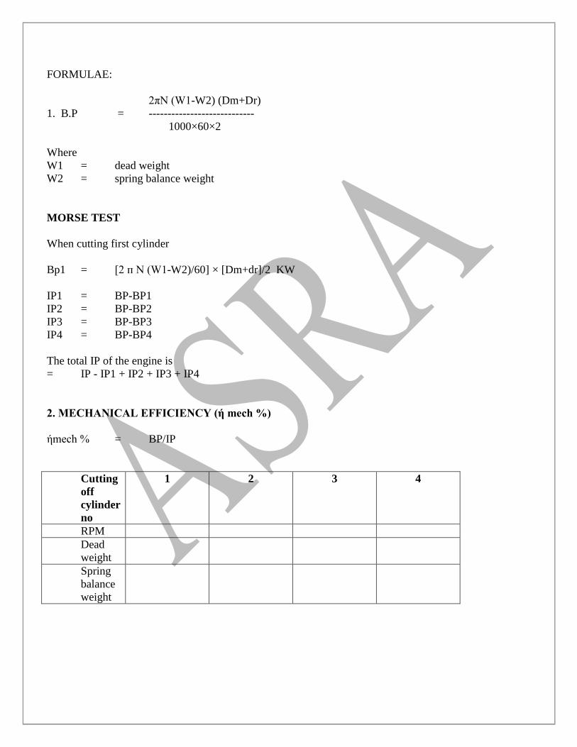
FORMULAE:
2πN (W1-W2) (Dm+Dr)
1. B.P = ----------------------------
1000×60×2
Where
W1 = dead weight
W2 = spring balance weight
MORSE TEST
When cutting first cylinder
Bp1 = [2 п N (W1-W2)/60] × [Dm+dr]/2 KW
IP1 = BP-BP1
IP2 = BP-BP2
IP3 = BP-BP3
IP4 = BP-BP4
The total IP of the engine is
= IP - IP1 + IP2 + IP3 + IP4
2. MECHANICAL EFFICIENCY (ή mech %)
ήmech % = BP/IP
Cutting
off
cylinder
no
1 2 3 4
RPM
Dead
weight
Spring
balance
weight
Procedure:
1. Now for the Morse test cut of the required cylinder by the respective knife switch. Adjust the
speed of the engine to its original value by reducing the load from the dynamometer without
changing the throttle position. Note down the power developed by three working cylinder. Thus
the difference of power developed between four cylinders & three cylinders is the Indicated Horse
Power (I.H.P) of the cut off cylinder.
2. Repeat the same procedure as in point 18 for the rest of the three cylinders individually and find
out their respective I.H.P. by adding the I.H.P of four individual cylinders, the total I.H.P of the
engine can be calculated.
3. Repeat the experiment for different load.
4. Reduce the load on the engine by removing the weights of the dynamometer and reducing the
throttle gradually. Declutch the dynamometer from the engine and bring the throttle to the close
position.
5. Turn off the ignition key and remove it from the switch.
6. Then close the fuel & cooling water supply to the engine.
EXPERIMENT NO 7
AIM-To check the performance of a diesel from no load to full load( at constant speed) for a single
cylinder /multicylinder engine in terms of brake power, indicated power, mechanical efficiency & specific
fuel consumption and further obtain power consumption curves and draw the heat balance sheet.
Description: Four cylinders, four stroke, petrol engine test rig with rope brake dynamometer mainly
consists of:
1. A four cylinder, four stroke petrol engine.
2. A rope break dynamometer.
3. A panel board arrangement.
4. A fuel input measuring arrangement.
5. Air intake measuring arrangement.
6. an arrangement for measuring the heat carried away by exhaust gasses and
7. an arrangement for measuring the heat carried away by cooling water.
A brief description and particulars on this test rig is given below:
1. MULTICYLINDER PETROL ENGINE:
A medium capacity four stroke, water cooled petrol engine is selected for experimental purpose. The
specification for the engine is as follows:
Rated horsepower : 8HP@ 1500 rpm
No. of cylinders : Four
The engine is complete with self starter, dynamo, lube oil filter, air cleaner, distributor, ignition coil,
exhaust silencer etc.
2. LOADING DEVICE:A rope break dynamometer arrangement with a brake drum coupled to the engine
shaft and provided with a cooling water arrangement, spring balance, a set of dead weights in Kg units,
mounted along with the engine on a substantial base plate to load the engine
3. PANEL BOARD ARRANGEMNET:
The units fitted on the dashboard are:
(a) an ignition & starting switch on the ignition circuit and to start the engine.
(b) An ammeter to read the charging or discharging current of the battery.
(c) A pilot lamp indicator for ignition.
(d) A high voltage knife switch assembly for cutting of each cylinder for morse test. With the help of
four individual knife switches, each cylinder can be cut off.
(e) Throttle valve control mechanism with an indicator to control the position of the throttle in relation
to the speed and load on the engine.
4. FUEL INPUT MEASURING ARRANGEMENT
Consists of self mounting type fuel tank of about 10 litres capacity suitably mounted on a stand , the stand
in turn fixed on the air tank, fuel goes from the reservoir to fuel filter through a 100ml burette. The burette
facilitates the measurement of the fuel consumption for a definite period of time with the help of a
stopwatch. The weight of fuel consumption can be calculated by multiplying the specific gravity of the
fuel with the volume.
5. AIR INTAKE MEASURING ARRANGEMENT
It consists of an air tank fitted on orifice plate with orifice dia 20mm and a differential manometer to
measure the rate of flow of air sucked by the engine. The co-efficient of discharge of orifice is about 0.62.
6. ARRANGEMENT FOR MEASURING THE HEAT CARRIED BY COOLING WATER
Suitable piping system is fitted to the engine for circulating the cooling water for the engine. Digital temp.
Indicator is provided to measure the inlet and outlet temp of cooling water. For measuring the rate of flow
of cooling water, a water meter is provided. With these entire arrangements one can find the heat carried
away by cooling water.
7. ARRANGEMENT FOR MEASURING THE HEAT CARRIED BY THE EXHAUST GAS
It consists of exhaust gas calorimeter to measure the heat carried by exhaust gasses. Exhaust gas
calorimeter consists a central tube & an outer jacket. Exhaust gases pass through central tube & water is
circulated in outer jacket to get the maximum temperature difference of exhaust gases at inlet & outlet of
calorimeter. The volume of water circulation is measured with the help of measuring cylinder and
stopwatch. Digital temperature is provided to get the inlet & outlet temperature of exhaust gases and water
circulated.
EXPERIMENTAL PROCEDURE
1. Fill oil in the oil sump of engine. It should be in between the marks provided on the oil dipstick. If
oil level is reduced, add clean oil (SAE-40) to the crankcase by opening the cover, provided at the top of
the engine.
2. Fill the petrol in the petrol tank.
3. Fill the manometer up to half of the height of manometer with water.
4. Fill the burette with petrol by opening the valve provided at the lefty side of burette.
5. Supply the petrol to the engine by opening the valve provided in the right side of burette. Supply
the main power.
6. Open cold water supply to the engine jacket.
7. Insert the ignition key and turn it in the clockwise direction to ignition on position. Turn the
ignition switch key further clockwise against the spring pressure to start the engine. As soon as the engine
starts, leave the ignition key, which returns to the ignition position automatically.
8. While starting, the clutch may be disengaged to start the engine at no load. After starting the
engine, the clutch may be slowly released and at the same time accelerate the engine gradually by opening
the throttle valve.
9. When engine start running smoothly, firstly load the engine slightly with the help of rope brake
dynamometer and then gradually increase the load. Then immediately open the cooling water to the brake
drum of the dynamometer.
10. Run the engine for 15 minutes so that it can be stabilize.
11. Note down the reading of spring balance & dead weights. Note the rpm with the help of hand
tachometer. This will give B.H.P of engine.
12. Close the petrol supply valve provided on the left side of the burette so that fuel flows from
burette. Note down the time to consume 50ml of petrol. It will give fuel consumption.
13. Now open the fuel supply valve which refill the burette & continue the petrol supply.
14. Note down the reading of manometer to calculate the air intake by the engine.
15. Note the temperature of the inlet and outlet of the water circulating through the engine jacket from
digital temperature indicator.
16. Measure the flow rate of water from water meter with the help of stop watch.
17. Note down the temperature of inlet and outlet of exhaust gases & water circulating through the
calorimeter. Measure the flow rate of water with the help of measuring cylinder & stopwatch.
18. Now for the Morse test cut of the required cylinder by the respective knife switch. Adjust the
speed of the engine to its original value by reducing the load from the dynamometer without changing the
throttle position. Note down the power developed by three working cylinder. Thus the difference of power
developed between four cylinders & three cylinders is the Indicated Horse Power (I.H.P) of the cut off
cylinder.
19. Repeat the same procedure as in point 18 for the rest of the three cylinders individually and find
out their respective I.H.P. by adding the I.H.P of four individual cylinders, the total I.H.P of the engine
can be calculated.
20. Repeat the experiment for different load.
21. Reduce the load on the engine by removing the weights of the dynamometer and reducing the
throttle gradually. Declutch the dynamometer from the engine and bring the throttle to the close position.
22. Turn off the ignition key and remove it from the switch.
23. Then close the fuel & cooling water supply to the engine.
PRECAUTION & MAINTENANCE INSTRUCTIONS
1. Always check the oil level in the engine before starting & make sure that sufficient oil is present in
the engine.
2. Change this oil as engine completes 150 hours of total running.
3. Open cold water supply to the engine before starting.
4. Fuel tank and fuel line should cleaned and free from foreign particles.
5. Pressing the ignition switch even after the engine starts and picks up speed will damage self starter
and shift mechanism.
6. A pressure gauge is provided to note the oil pressure which should not be less than 2 kg/cm² when
the engine runs.
7. themorse test should be carried out only after the engine running conditions are stabilized at the
required B.H.P.
8. When a cylinder is cut off adjust the speed and load of the engine quickly because large time laps
might result in change in the working conditions of the engine.
9. Do not attempt to cut off two cylinders simultaneously, since it can develop severe engine
vibrations.
SPECIFICATIONS:
Engine : 4 cylinder, 4 stroke, inclined, water cooled
H.P : 8H.P @1500 rpm
Compression ratio : 8.7:1
STANDARD DATA:
D = Bore of engine = 68.5
L = Stroke of engine = 72mm
A = cross sectional area of orifice = 3.142×10‾4
Do = Diameter of orifice = 20mm
Dm = Diameter of brake drum = 300mm
Dr = Diameter of rope = 16mm
Cd = Coefficient of discharge = 0.62
ρa = Density of air at 0°C = 1.293 kg/m³
ρm = Density of manometer fluid i.e. water = 1000kg/m³
g = Acceleration due to gravity = 9.81m/s²
T1 = Temp of water at engine inlet in °C
T2 = Temp of water at outlet in °C
T3 = Temp of exhaust gasses at inlet of calorimeter °C
T4 = Temp of exhaust gasses at outlet of calorimeter °C
T5 = Temp of water at inlet of calorimeter °C
T6 = Temp of water at outlet of calorimeter °C
Ta = Ambient temperature °C
1 H.P = 746 watts
Cp = Specific heat of water = 4.18KJ/kg°C
CV = Calorific value of petrol = 44581KJ/KG
Specific gravity of petrol = 0.69gm/cc
2. FUEL CONSUMPTION
X/t × specific gravity of fuel/1000
Wf = ------------------------------------------
3600
where:
X = volume of fuel consumed (ml) (1ml=1cm³)
T = time taken for X (seconds)
3. SPECIFIC FUEL CONSUMPTION
Fuel consumption
= ---------------------- KJ/Kw.hr
BP
4. HEAT IN FUEL SUPPLIED (Hf)
Hf = Wf × CV KJ/min
Where Wf = mass of fuel supplied Kg/min
5. BRAKE THERMAL EFFICIENCY (Ή BREAK %)
ή break % = BP/Wf × C.V
6. HEAT BALANCE SHEET
a) Heat equivalent
Hbp = (BP× 60) KJ/min
b) Heat carried away by engine jacket cooling water (Hcw)
Hcw = mwe× CP( T2-T1) KJ/min
Where
Mwe mass of cooling water supplied jacket of engine Kg/min
c) Heat carried by exhaust gasses (Heg)
Heg = mw × Cpw × (T6-T5) × (T3-Ta)/(T3-T4)
Ta = T2
where
mwe = mass of cooling water circulating in calorimeter in Kg/min
D) Heat Lost In Radiation & Unaccounted Losses (Hun)
Hun = Hf-(Hbp+Hew+Hew) KJ/min
7. SWEPT VOLUME
= п/4 × D² ×L × (cycles/s) × no. of cylinders
= (п/4) × D² × L × (1500 ×4)/ (2 × 60) m³/s
8. VOLUMETRIC EFFICIENCY
= (volume of air actually sucked during suction stroke (Qa) / swept volume) × 100
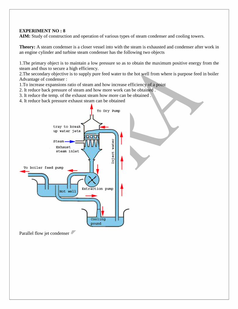
EXPERIMENT NO : 8
AIM: Study of construction and operation of various types of steam condenser and cooling towers.
Theory: A steam condenser is a closer vessel into with the steam is exhausted and condenser after work in
an engine cylinder and turbine steam condenser has the following two objects
1.The primary object is to maintain a low pressure so as to obtain the maximum positive energy from the
steam and thus to secure a high efficiency.
2.The secondary objective is to supply pure feed water to the hot well from where is purpose feed in boiler
Advantage of condenser :
1.To increase expansions ratio of steam and how increase efficiency of a point
2. It reduce back pressure of steam and how more work can be obtained .
3. It reduce the temp. of the exhaust steam how more can be obtained .
4. It reduce back pressure exhaust steam can be obtained
Parallel flow jet condenser
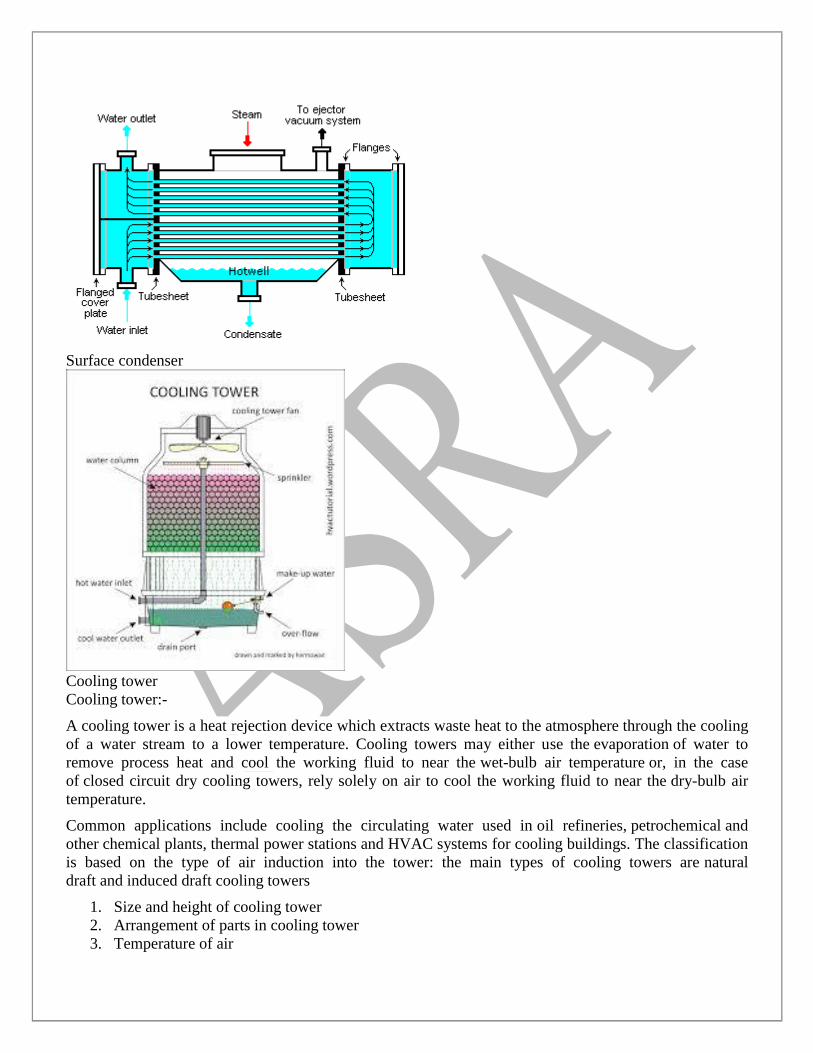
Surface condenser
Cooling tower
Cooling tower:-
A cooling tower is a heat rejection device which extracts waste heat to the atmosphere through the cooling
of a water stream to a lower temperature. Cooling towers may either use the evaporation of water to
remove process heat and cool the working fluid to near the wet-bulb air temperature or, in the case
of closed circuit dry cooling towers, rely solely on air to cool the working fluid to near the dry-bulb air
temperature.
Common applications include cooling the circulating water used in oil refineries, petrochemical and
other chemical plants, thermal power stations and HVAC systems for cooling buildings. The classification
is based on the type of air induction into the tower: the main types of cooling towers are natural
draft and induced draft cooling towers
1. Size and height of cooling tower
2. Arrangement of parts in cooling tower
3. Temperature of air

4. Humidity of air
REQUIREMENT OF STEAM CONDENSING PLANT:
1. Boiler feed pump
2. Cooling tower
3. Cooling water pump
4. Condenser
5. Condenser pump
6. Hot well