Embed Size (px)
Citation preview
Study of Handover Techniques for 4G Network MIMO Systems
1 Jian-Sing Wang,
2 Jeng-Shin Sheu
1 National Yunlin University of Science and Technology Department of CSIE
E-mail: [email protected] 2 National Yunlin University of Science and Technology Department of CSIE
E-mail: [email protected]
Abstract—For the upcoming 4G systems, network
multiple-input multiple-output (MIMO) and inter-cell interference coordination (ICIC) are two of key techniques adopted in 4G systems to mitigate the serious inter-cell interference (ICI) and improve coverage and cell-edge throughput. Network MIMO is referred to as coordinated multi-point (CoMP) in LTE-A. In this paper, we propose a simulation platform to analyze the handover issue for downlink CoMP transmissions in LTE-A cellular systems. Among the variety of ICIC strategies, we apply the widely adopted soft frequency reuse (SFR) and the fractional frequency reuse (FFR) schemes. Both schemes are based on the idea of applying a frequency reuse factor of one in cell-center areas, and a higher reuse factor in cell-edge areas. Therefore, the ICI is reduced at the expense of the available frequency resources for each cell.
Keywords— LTE; Network MIMO; Handover
I. INTRODUCTION
A handover platform is built to simulate user’s mobility around cells in fourth generation(4G) cellular system environment with network MIMO, Orthogonal Frequency Division Multiplexing(OFDM) and cell sectorization to mitigate interference and improve cell edge user’s performance. With cell sectorization, frequency band is divided to cell center and cell edge to mitigate interference and in cell edge is further divided to several segments, each allocated to a sector. In this simulation platform we add network MIMO and OFDM transmit signal according to user’s position without increase transmission bandwidth and power to achieve faster data rate, high signal quality and also avoid multi-path effect.
II. SYSTEM MODEL
In wireless communication, signal transmitted via a assign bandwidth also called channel. If there have no obstruction between user and base station, we can easily receive signal in this free space propagation model. Otherwise, signal will be shadowing or absorb for example building, tree or
cars. It will cause serious signal fading and multi-path effect. These case we discuss below: A. Propagation Path Loss Transmission signal power is squared inversely proportional to distance between user and base station (BS). In free space propagation model, the transmission power that received by user can be written as
(1)
Where is receive signal power at distance d, is transmission power, and means transmit and received antenna gain, is wavelength of waves. Consider directional antenna gain and circuit loss, we can’t obtain received power when d = 0 in formula (1). Then we set a reference distance and the received power can be written as
(
If user not in free space environment, the path loss exponent will change with environment so we can present logarithmic distance path loss model. Because path loss at distance d squared proportional to distance, the path loss can written as
(3)
We put formula (3) in dB can be written as (4)
(4)
Where is path loss exponent that effect path loss speed, table 1 shows path loss exponent in different environment.
TABLE 1: PATH LOSS EXPONENTIAL IN VARIOUS ENVIRONMENT
Environment Path loss exponent,
Proceedings of the 2013 International Conference on Electronics, Signal Processing and Communication Systems
137
Free space 2 Urban area cellular radio 2.7 to 3.5
Shadowed urban area cellular radio 3 to 5
In building line-of-sight 1.6 to 1.8 Obstructed in building 4 to 6 Obstructed in factories 2 to 3
B. Large Scale Fading
The path loss we discussed before is consider about distance, but in real situation the transmitted signal will suffered shadowing fading effect. Even the distance between user and base station is the same, but the topography and object on signal transmit path is not always so. As we discuss above, the receive signal power is different at the same distance. The path loss present log-normal random variable so we can rewrite formula (4) to (5)
(5)
Formula (5) in dBm is written as (6)
(6)
Where is Gaussian random variable, is standard deviation general for 8 dB. In formula (6) is transmission power, is path loss power from base station to user. C. Small scale fading In this section we discuss small scale fading occur in short period of time (ns) and cause radio signal fluctuation rapidly, so we ignore large scale fading effect because different observation time interval. When signal transmitted by directional antenna via a non-line of sight(NLOS) path, it will suffer reflection, diffraction ,scattering than cause multi-path effect or be absorbed. In urban environment, multi-path effect can be much serious than a village because shadowing objects of urban also more than village. Multi-path effect is shown in Fig. 1.
Fig. 1 Multi-path effect
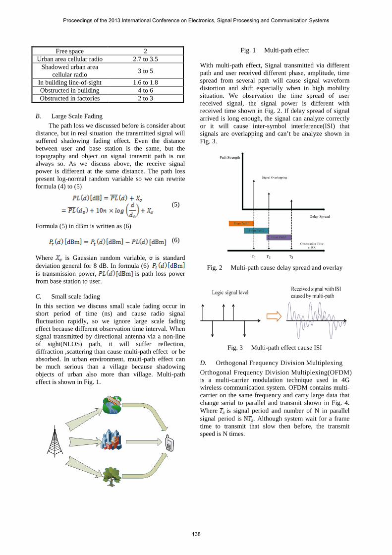
With multi-path effect, Signal transmitted via different path and user received different phase, amplitude, time spread from several path will cause signal waveform distortion and shift especially when in high mobility situation. We observation the time spread of user received signal, the signal power is different with received time shown in Fig. 2. If delay spread of signal arrived is long enough, the signal can analyze correctly or it will cause inter-symbol interference(ISI) that signals are overlapping and can’t be analyze shown in Fig. 3.
Fig. 2 Multi-path cause delay spread and overlay
Fig. 3 Multi-path effect cause ISI
D. Orthogonal Frequency Division Multiplexing Orthogonal Frequency Division Multiplexing(OFDM) is a multi-carrier modulation technique used in 4G wireless communication system. OFDM contains multi-carrier on the same frequency and carry large data that change serial to parallel and transmit shown in Fig. 4. Where is signal period and number of N in parallel signal period is . Although system wait for a frame time to transmit that slow then before, the transmit speed is N times.
Proceedings of the 2013 International Conference on Electronics, Signal Processing and Communication Systems
138
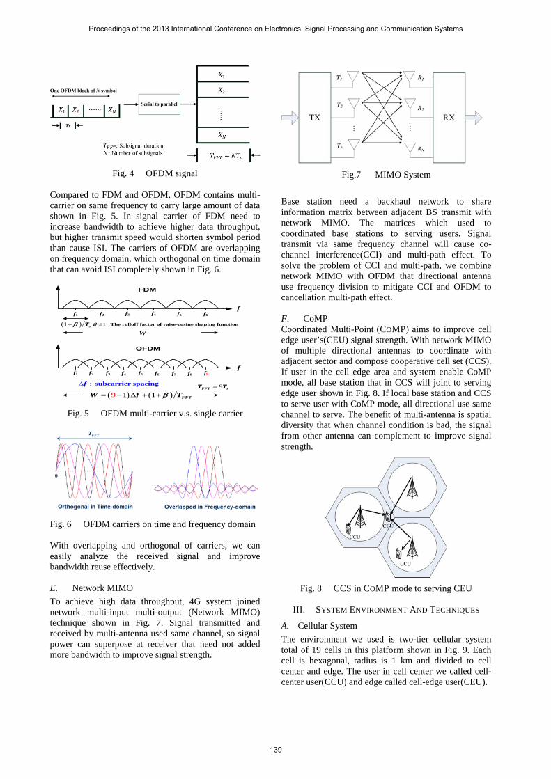
Fig. 4 OFDM signal
Compared to FDM and OFDM, OFDM contains multi-carrier on same frequency to carry large amount of data shown in Fig. 5. In signal carrier of FDM need to increase bandwidth to achieve higher data throughput, but higher transmit speed would shorten symbol period than cause ISI. The carriers of OFDM are overlapping on frequency domain, which orthogonal on time domain that can avoid ISI completely shown in Fig. 6.
f
f
FDM
OFDM
f2f1 f6f4f3 f5
f1 f2 f9f3 f4 f5 f6 f7 f8
: subcarrier spacingf∆
W
( ) ( )1 19 FFTW f Tβ= − ∆ + +
( )1 sTβ+ 1: The rolloff factor of raise-cosine shaping functionβ ≤
9FFT sT T=
Fig. 5 OFDM multi-carrier v.s. single carrier
Fig. 6 OFDM carriers on time and frequency domain
With overlapping and orthogonal of carriers, we can easily analyze the received signal and improve bandwidth reuse effectively. E. Network MIMO To achieve high data throughput, 4G system joined network multi-input multi-output (Network MIMO) technique shown in Fig. 7. Signal transmitted and received by multi-antenna used same channel, so signal power can superpose at receiver that need not added more bandwidth to improve signal strength.
Fig.7 MIMO System
Base station need a backhaul network to share information matrix between adjacent BS transmit with network MIMO. The matrices which used to coordinated base stations to serving users. Signal transmit via same frequency channel will cause co-channel interference(CCI) and multi-path effect. To solve the problem of CCI and multi-path, we combine network MIMO with OFDM that directional antenna use frequency division to mitigate CCI and OFDM to cancellation multi-path effect. F. CoMP Coordinated Multi-Point (COMP) aims to improve cell edge user’s(CEU) signal strength. With network MIMO of multiple directional antennas to coordinate with adjacent sector and compose cooperative cell set (CCS). If user in the cell edge area and system enable CoMP mode, all base station that in CCS will joint to serving edge user shown in Fig. 8. If local base station and CCS to serve user with CoMP mode, all directional use same channel to serve. The benefit of multi-antenna is spatial diversity that when channel condition is bad, the signal from other antenna can complement to improve signal strength.
Fig. 8 CCS in COMP mode to serving CEU
III. SYSTEM ENVIRONMENT AND TECHNIQUES
A. Cellular System The environment we used is two-tier cellular system total of 19 cells in this platform shown in Fig. 9. Each cell is hexagonal, radius is 1 km and divided to cell center and edge. The user in cell center we called cell-center user(CCU) and edge called cell-edge user(CEU).
Proceedings of the 2013 International Conference on Electronics, Signal Processing and Communication Systems
139
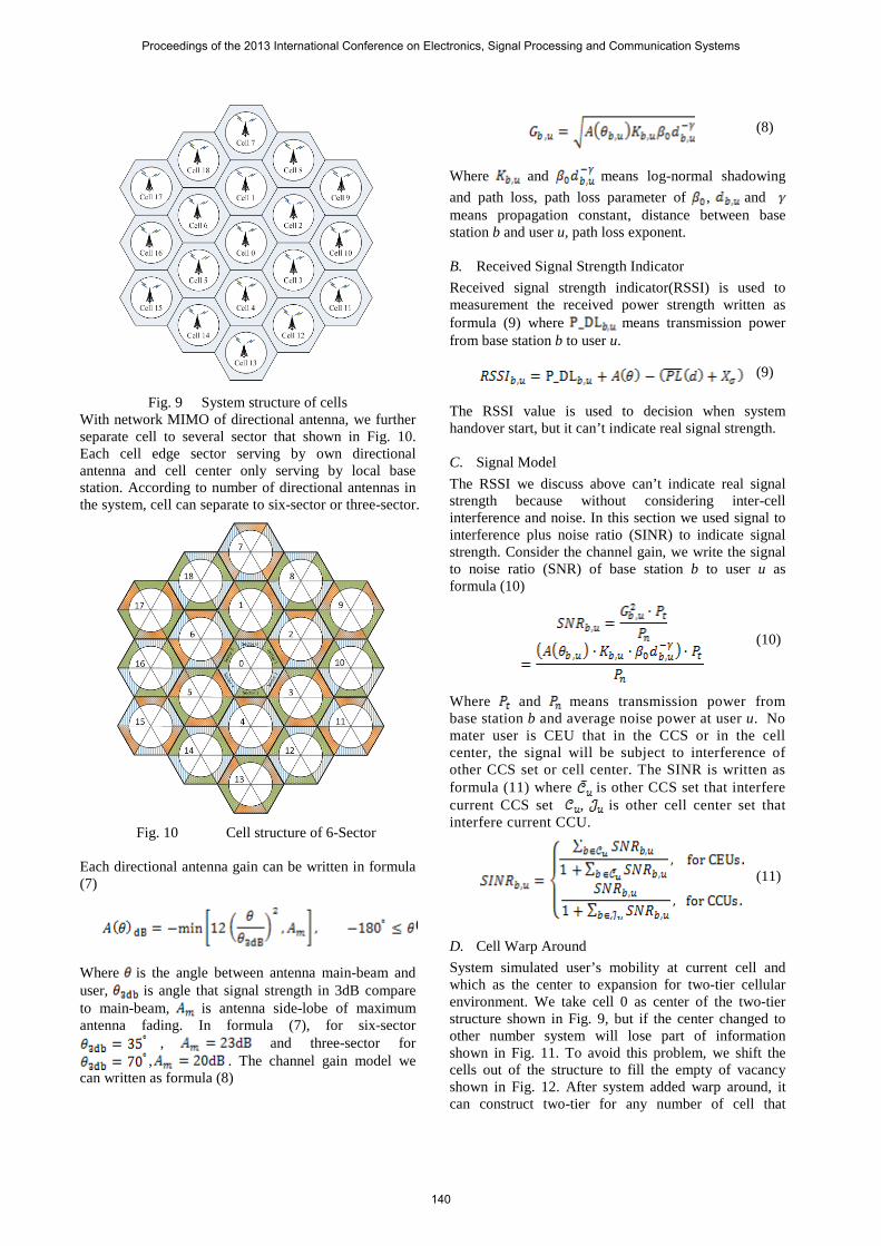
Fig. 9 System structure of cells
With network MIMO of directional antenna, we further separate cell to several sector that shown in Fig. 10. Each cell edge sector serving by own directional antenna and cell center only serving by local base station. According to number of directional antennas in the system, cell can separate to six-sector or three-sector.
Fig. 10 Cell structure of 6-Sector
Each directional antenna gain can be written in formula (7)
(
Where is the angle between antenna main-beam and user, is angle that signal strength in 3dB compare to main-beam, is antenna side-lobe of maximum antenna fading. In formula (7), for six-sector
, and three-sector for , . The channel gain model we
can written as formula (8)
(8)
Where and means log-normal shadowing and path loss, path loss parameter of , and means propagation constant, distance between base station b and user u, path loss exponent. B. Received Signal Strength Indicator Received signal strength indicator(RSSI) is used to measurement the received power strength written as formula (9) where means transmission power from base station b to user u.
(9)
The RSSI value is used to decision when system handover start, but it can’t indicate real signal strength. C. Signal Model The RSSI we discuss above can’t indicate real signal strength because without considering inter-cell interference and noise. In this section we used signal to interference plus noise ratio (SINR) to indicate signal strength. Consider the channel gain, we write the signal to noise ratio (SNR) of base station b to user u as formula (10)
(10)
Where and means transmission power from base station b and average noise power at user u. No mater user is CEU that in the CCS or in the cell center, the signal will be subject to interference of other CCS set or cell center. The SINR is written as formula (11) where is other CCS set that interfere current CCS set , is other cell center set that interfere current CCU.
(11)
D. Cell Warp Around System simulated user’s mobility at current cell and which as the center to expansion for two-tier cellular environment. We take cell 0 as center of the two-tier structure shown in Fig. 9, but if the center changed to other number system will lose part of information shown in Fig. 11. To avoid this problem, we shift the cells out of the structure to fill the empty of vacancy shown in Fig. 12. After system added warp around, it can construct two-tier for any number of cell that
Proceedings of the 2013 International Conference on Electronics, Signal Processing and Communication Systems
140
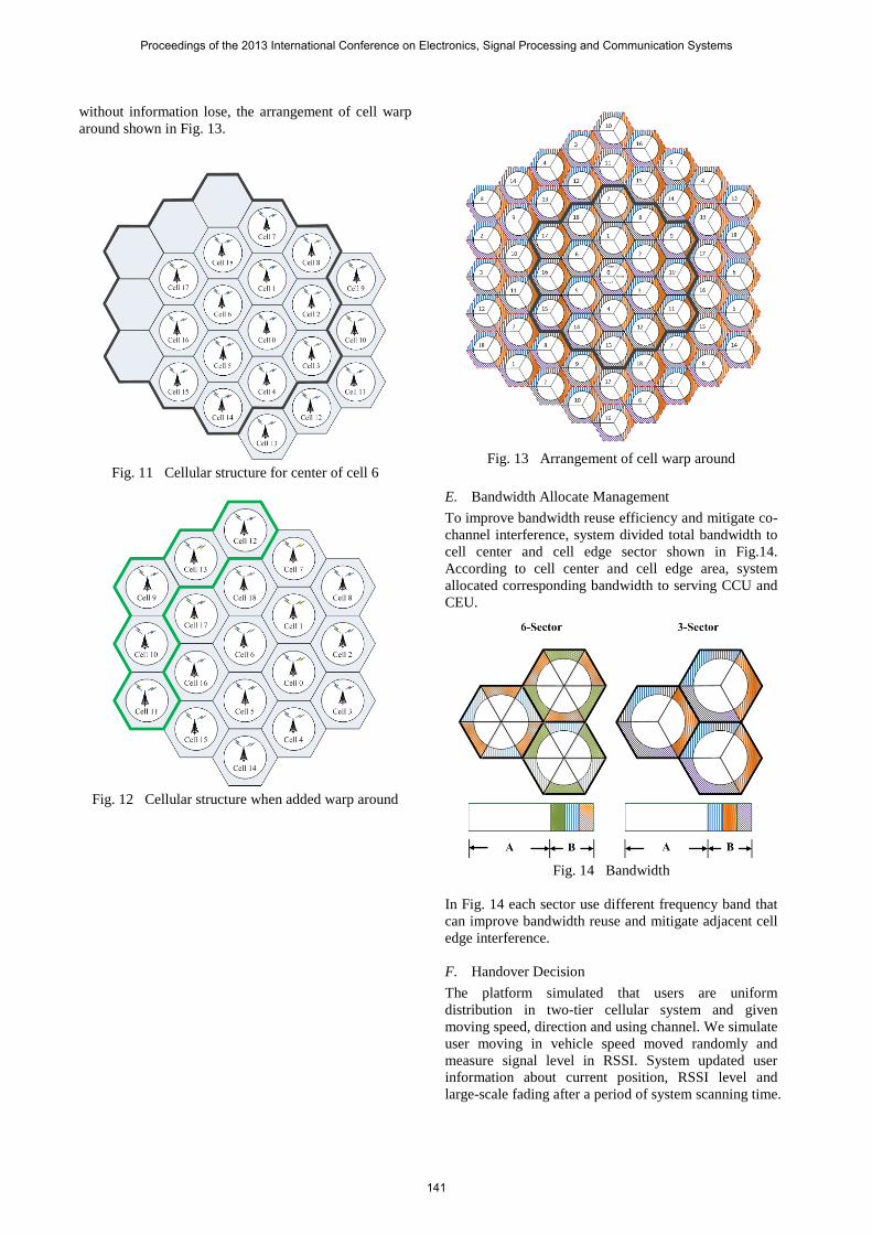
without information lose, the arrangement of cell warp around shown in Fig. 13.
Fig. 11 Cellular structure for center of cell 6
Fig. 12 Cellular structure when added warp around
Fig. 13 Arrangement of cell warp around
E. Bandwidth Allocate Management To improve bandwidth reuse efficiency and mitigate co-channel interference, system divided total bandwidth to cell center and cell edge sector shown in Fig.14. According to cell center and cell edge area, system allocated corresponding bandwidth to serving CCU and CEU.
Fig. 14 Bandwidth
In Fig. 14 each sector use different frequency band that can improve bandwidth reuse and mitigate adjacent cell edge interference. F. Handover Decision The platform simulated that users are uniform distribution in two-tier cellular system and given moving speed, direction and using channel. We simulate user moving in vehicle speed moved randomly and measure signal level in RSSI. System updated user information about current position, RSSI level and large-scale fading after a period of system scanning time.
Proceedings of the 2013 International Conference on Electronics, Signal Processing and Communication Systems
141
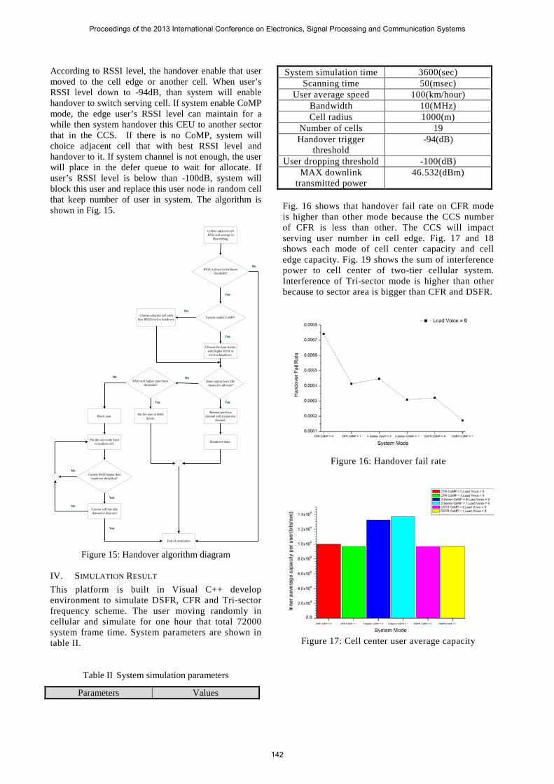
According to RSSI level, the handover enable that user moved to the cell edge or another cell. When user’s RSSI level down to -94dB, than system will enable handover to switch serving cell. If system enable CoMP mode, the edge user’s RSSI level can maintain for a while then system handover this CEU to another sector that in the CCS. If there is no CoMP, system will choice adjacent cell that with best RSSI level and handover to it. If system channel is not enough, the user will place in the defer queue to wait for allocate. If user’s RSSI level is below than -100dB, system will block this user and replace this user node in random cell that keep number of user in system. The algorithm is shown in Fig. 15.
Collect adjacent cell RSSI and arrange in
Descending.
Choose the base station with higher RSSI in CCS to handover.
Release previous channel and accept new
channel.
Put the user in defer queue.Block user.
Choose adjacent cell with best RSSI level to handover.
Handover done.
End of simulation
Put the user node back in random cell.
Current cell has idle channel to allocate?
RSSI is down to handover threshold?
System enable CoMP?
No
Yes
No
Base station have idle channel to allocate?
Yes
No
Yes
RSSI still higher than block threshold?
No
Current RSSI higher than handover threshlod?
Yes
Yes
No
No
Yes
Figure 15: Handover algorithm diagram
IV. SIMULATION RESULT This platform is built in Visual C++ develop environment to simulate DSFR, CFR and Tri-sector frequency scheme. The user moving randomly in cellular and simulate for one hour that total 72000 system frame time. System parameters are shown in table II.
Table II System simulation parameters
Parameters Values
System simulation time 3600(sec) Scanning time 50(msec)
User average speed 100(km/hour) Bandwidth 10(MHz) Cell radius 1000(m)
Number of cells 19 Handover trigger
threshold -94(dB)
User dropping threshold -100(dB) MAX downlink
transmitted power 46.532(dBm)
Fig. 16 shows that handover fail rate on CFR mode is higher than other mode because the CCS number of CFR is less than other. The CCS will impact serving user number in cell edge. Fig. 17 and 18 shows each mode of cell center capacity and cell edge capacity. Fig. 19 shows the sum of interference power to cell center of two-tier cellular system. Interference of Tri-sector mode is higher than other because to sector area is bigger than CFR and DSFR.
Figure 16: Handover fail rate
Figure 17: Cell center user average capacity
Proceedings of the 2013 International Conference on Electronics, Signal Processing and Communication Systems
142
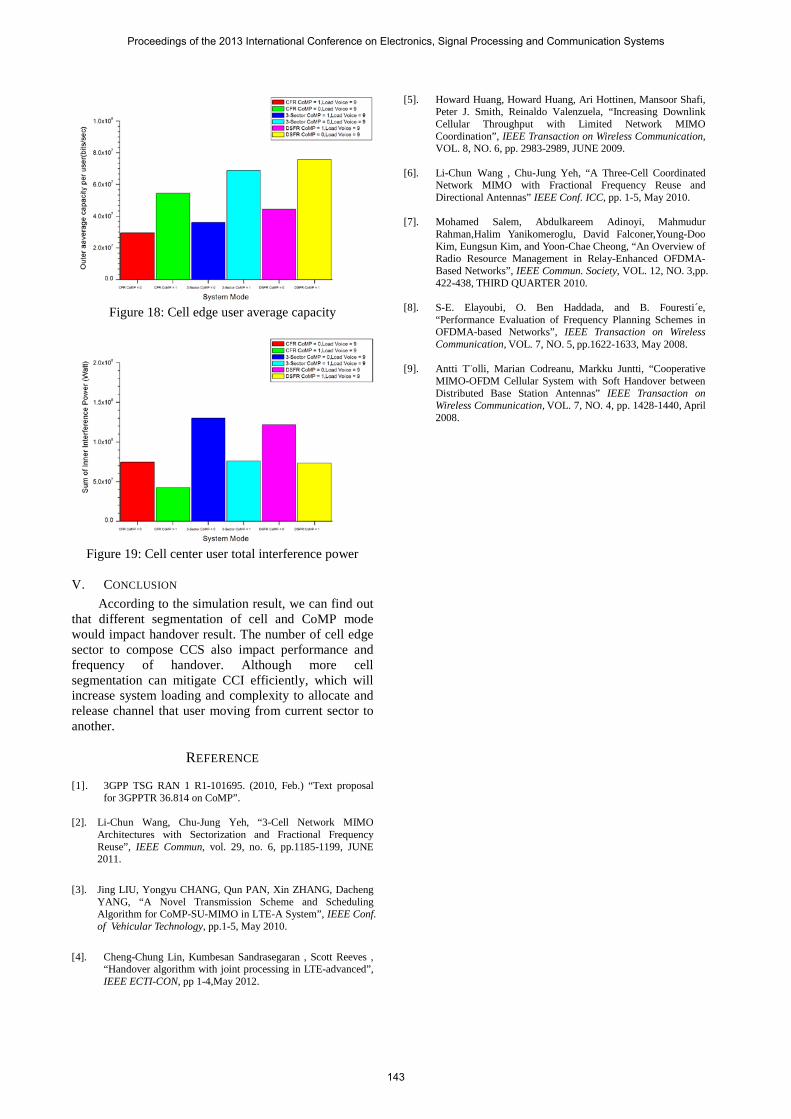
Figure 18: Cell edge user average capacity
Figure 19: Cell center user total interference power
V. CONCLUSION
According to the simulation result, we can find out that different segmentation of cell and CoMP mode would impact handover result. The number of cell edge sector to compose CCS also impact performance and frequency of handover. Although more cell segmentation can mitigate CCI efficiently, which will increase system loading and complexity to allocate and release channel that user moving from current sector to another.
REFERENCE [1]. 3GPP TSG RAN 1 R1-101695. (2010, Feb.) “Text proposal
for 3GPPTR 36.814 on CoMP”. [2]. Li-Chun Wang, Chu-Jung Yeh, “3-Cell Network MIMO
Architectures with Sectorization and Fractional Frequency Reuse”, IEEE Commun, vol. 29, no. 6, pp.1185-1199, JUNE 2011.
[3]. Jing LIU, Yongyu CHANG, Qun PAN, Xin ZHANG, Dacheng YANG, “A Novel Transmission Scheme and Scheduling Algorithm for CoMP-SU-MIMO in LTE-A System”, IEEE Conf. of Vehicular Technology, pp.1-5, May 2010.
[4]. Cheng-Chung Lin, Kumbesan Sandrasegaran , Scott Reeves , “Handover algorithm with joint processing in LTE-advanced”, IEEE ECTI-CON, pp 1-4,May 2012.
[5]. Howard Huang, Howard Huang, Ari Hottinen, Mansoor Shafi, Peter J. Smith, Reinaldo Valenzuela, “Increasing Downlink Cellular Throughput with Limited Network MIMO Coordination”, IEEE Transaction on Wireless Communication, VOL. 8, NO. 6, pp. 2983-2989, JUNE 2009.
[6]. Li-Chun Wang , Chu-Jung Yeh, “A Three-Cell Coordinated
Network MIMO with Fractional Frequency Reuse and Directional Antennas” IEEE Conf. ICC, pp. 1-5, May 2010.
[7]. Mohamed Salem, Abdulkareem Adinoyi, Mahmudur
Rahman,Halim Yanikomeroglu, David Falconer,Young-Doo Kim, Eungsun Kim, and Yoon-Chae Cheong, “An Overview of Radio Resource Management in Relay-Enhanced OFDMA-Based Networks”, IEEE Commun. Society, VOL. 12, NO. 3,pp. 422-438, THIRD QUARTER 2010.
[8]. S-E. Elayoubi, O. Ben Haddada, and B. Fouresti´e,
“Performance Evaluation of Frequency Planning Schemes in OFDMA-based Networks”, IEEE Transaction on Wireless Communication, VOL. 7, NO. 5, pp.1622-1633, May 2008.
[9]. Antti T¨olli, Marian Codreanu, Markku Juntti, “Cooperative
MIMO-OFDM Cellular System with Soft Handover between Distributed Base Station Antennas” IEEE Transaction on Wireless Communication, VOL. 7, NO. 4, pp. 1428-1440, April 2008.
Proceedings of the 2013 International Conference on Electronics, Signal Processing and Communication Systems
143