Embed Size (px)
Citation preview
INCE the discovery and characteriza- The extreme speed of detonation processes and the destructive effects of S tion of the form of explosive decomposi- high explosives have rendered experimental investigations of the mechanism tion known as detonation by Abel ( 1 ) and most difficult. Photographic recording of the radiation emitted during Berthelot (4, 6), the experimental develop- explosion is particularly adaptable, and the methods of Dixon and Laffitte ment of significant details has lagged be- were therefore extended to a higher range of recording speed. A pre- hind theoretical speculations. The hy- cision rotating-drum camera capable of producing a film speed of 180 drodynamic theory of Chapman (7) and meters per second was built. Its resolving time is about 1 0 - 6 second. Jouguet (11) as perfected by Becker (5) Since the duration of the most energetic detonation reactions is even was given experimental confirmation by shorter, a camera was made with a speed about ten times as great, through Lewis (16), as applied to the case of deto- application of a mirror mounted on an air-driven rotor of the Beams type. nation in gaseous mixtures. The theory of Explosions of as much as 1-kg. charges of high explosives can be photo- detonation as ordinarily expressed is based graphed without damage to the apparatus. The photographic method is on the assumption of complete homo- useful in clarifying the important details of the detonation mechanism in geneity of the explosive system. While solid and liquid explosives. The methods described have been used in this such an assumption is permissible in the laboratory for the past five years with success. They have been particularly case of liquid explosives, it is not correct valuablein studying the behavior of complex mixtures of explosive substances. for solids. The fact is now well established tha t the particle size of pure explosive com- pounds may have a pronounced effect on the velocity of detona- tained by coarse-grained explosives must be due to incomplete tion a t a given charge density. Effects of this type are common development of energy a t the time of passage of the explosion in the case of commercial explosives, such as ammonium nitrate wave. I n the case of composite explosives, such as dynamites dynamites, where the practice for years has been to control the which contain some nonexplosive but reactive ingredients, a con- detonation velocity by varying the particle size of the am- siderable amount of energy is developed behind the detonation monium nitrate. wave as evidenced by afterburning apparent in detonation
The theory of detonation in its simple form is also independent photographs. Here again the particle size of the nonexplosive of kinetic factors such as the speed and completeness of energy- ingredients can have pronounced effects on detonation velocity. producing reactions occurring during detonation. It seems It is evident from these facts that the detonation velocity of a Teasonable to assume that the reduced detonation velocity at- solid explosive system is subject t o influence by factors not repre-
sented in the Dublished theories of detonation. 0 . 0 It was evident from consideration of past work that further ad-
vances in the explanation and understanding of detonation The above photograph is an extekior view of the chamber used for photographing explosives.
r .. ad I N b U S T R I A L : A N D EN G IN E E R I N G C H EM I S T R Y Vol. 36, No. 1
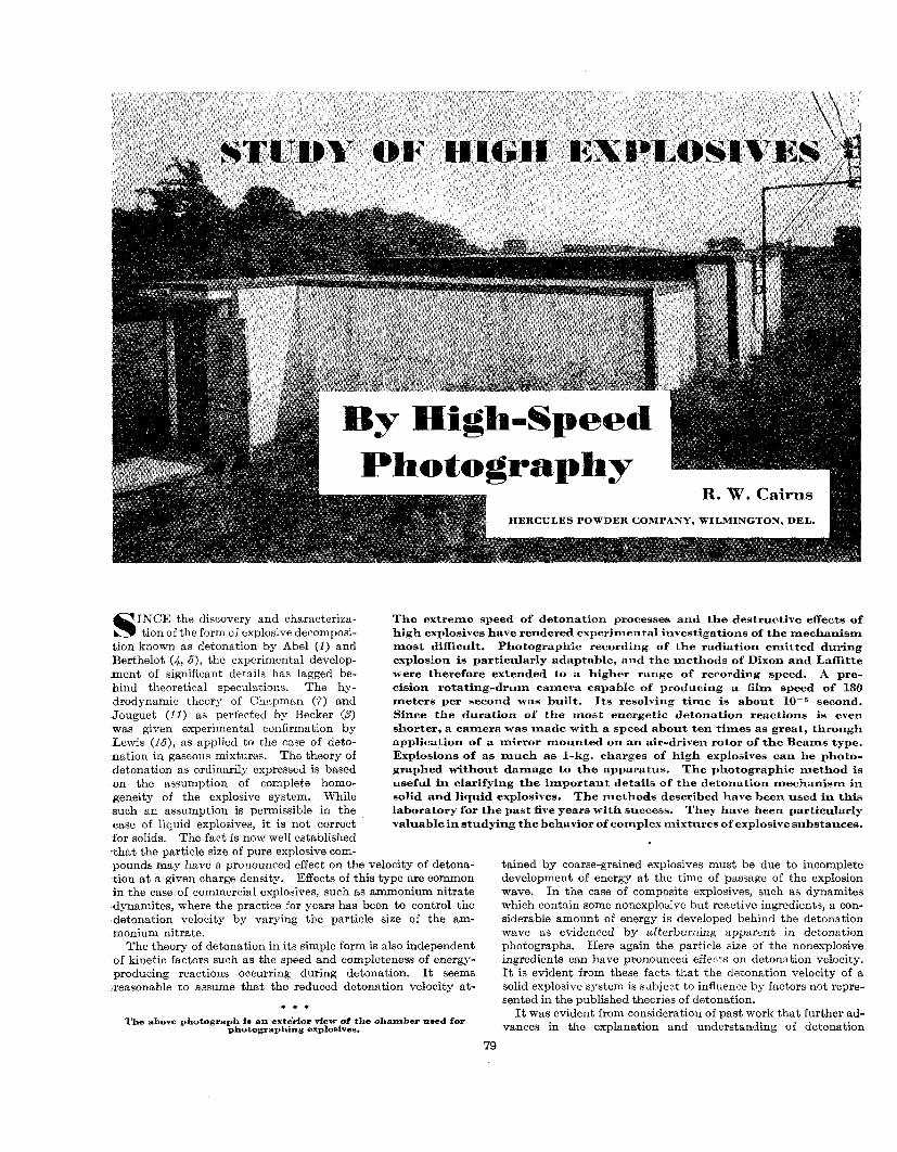
Figure 1. Camera- with Top
A. Top --uLIuLL
B. D-mm '
p h e n o m e n a de- pended on the de- velopment of im-
review of vanous sirably large in possibilities led to s m a l l c h a r g e s . the adoption of a Furthermore a method which has a l r e a d y been ap- p l ied w i t h some suo c e ss-namely,
oreciable amounts uninfluenced bv I\ ' bf energy are in- the effects of the
volved in detona- initiating means. tion reactions that Quantitatively , almost invariably the minimum di- the temperatures of t h e r e a c t i n g
Figure 2. Sectional Drawing of Rotating-Drum Camera
mensions approxi- mate 20 and 50
A . 180-cycle a. e. synchronous motor D I ..-- 3 -1 .-.. >-. Y. m*"mx.muxn nlluy urllm C. Bronze housing D . Glass prism E. Photographic lens F. Slit and aperture G. Recessed groove for film
to
he required charge weights is of practical significance ercial dynamites also fall
Therefore, to be widely ipment must be sufficiently
.. . . . . xplosion of a 1-kg. charge of R to the application of a remote means of observation which is essen- ti81 in dealing with high explosives, if the apparatus is to be used Much of the Past work has been limited to considerably smaller for more than a single experiment. Furthermore, photographic Parisot (I?), using the apparatus developed by Laffitte recording is particularly appropriate since i t satisfies the require- and Patry (f4), reported ments of high recording speed, and the records obtained are fixed in that he was limited to reasonably permanent form. No other recording method availa-
hlgh-strength exp'osive*
Charges.
ble at present combines so many advantages for this application. Dixon (8) photographically recorded the radiation produced by
explosions in gases. The method was thoroughly developed for gaseous explosives by Bone and co-workers (6). It was first applied to solid explosives by Laffitte (IS), and further investi- gated by Laffitte and Patry ( f 4 , 18). The Safety in Mines Re- search Board in England sponsored a program of photographic research on high explosives ( f O , f Q , 20).
~
PHOTOGRAPHY OF EXPLOSIVES
The results of the work mentioned and of preliminary expari- ments carried out a t the Hercules Experiment Station indicated the desirability of improvements aloqg several lines. Above all, the duration of detonation processes was extremely short; for ex- ample, the time required for the development of the maximum temperature at a given point in an explosive was of the order of a microsecond, as estimated from the duration of luminosity asso- ciated with the primary detonation wave. Hence, detailed in- formation on the propagation of detonation could not be obtained unless the apparatus was capable of resolving events separated by less than 10-6 second. This requirement was not met in any of the work of previous investigators. Consequently, efforts were concentrated on development of equipment of a higher recording speed.
Another important consideration is the magnitude of the charges fired. Available information (12) and unpublished work of the author indicated that the complicating influence of such
charges not exceeding 9 mm. i n d i a m e t e r t o a v o i d damaging his apparatus. Examination of the detailed results shows that the det- onation process may be critically affected by charge diameter a t such small sizes and thus give rise to many complicating effects- which are not easily inter- preted and may not be s ign if i c a n t except under special conditions.
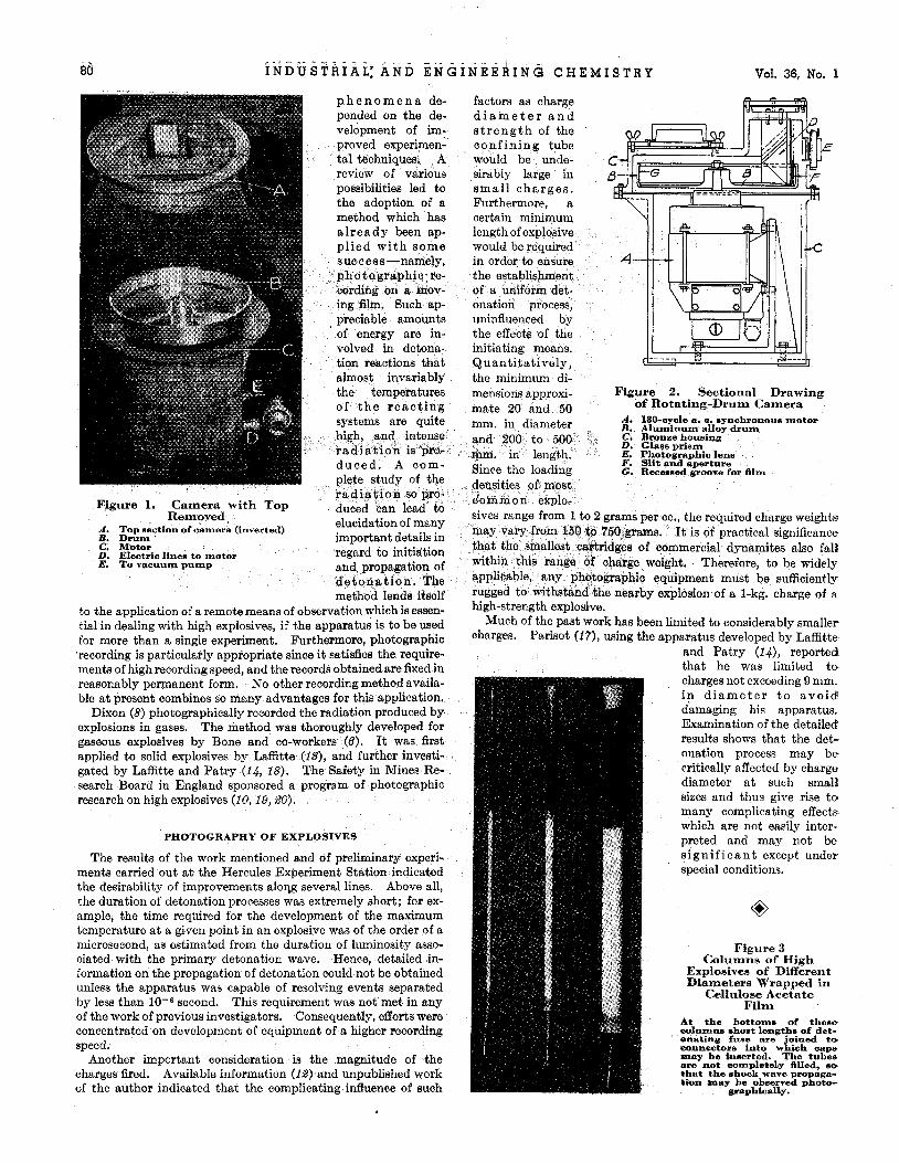
Figure 3 Columns of High
Explosives of Different Diameters Wrapped in
Cellulose Acetate Film
A t the bottoms of these oolumns short lengths of det- onating fuse are joined to eonnectoms into which cape may be inserted. The tubes are not complebeLy filled (I@ that the shook wave propiga- tion m a y be observed photo-
$raphically.
January, 1944 I N D U S T R I A L A N D E N G I N E E R I N G C H E M I S T R Y 81
slightly lower pressure. There- fore, operation is usually carried out a t 100 mm. of mercury 0: less. Under this condition, maximum speed is reached in less than one minute after current is applied.
Details of the optical system are shown in Figure 2. A right-angle prism is mounted behind a lens s o as to reflect doubly the light radiated by the explosion, first from its original horizontal course downwards and then back to a horizontal course in the opposite direction. Thus, the image formed by the lens falls on the inner sur- face of the drum and may be brought to focus by moving the prism in its holder along slots in the top of the bronze camera hous- ing, arranged to permit variation in the length of the optical path. The lens aperture may be varied from f/2.5 to f/32, and the entire range has been found useful with various explosives. No shutter is needed since the photographs are obtained in a dark chamber, and only the light from the explosion reaches the camera. A lens cover is used when- ever artificial illumination of the dark chamber is necessary.
OPERATION AND APPLICATIONS Figure 4. Explosion Chamber Designed to Attenuate Noise, Showing Camera Window and Steel Housing. Cinder Concrete Block Lined Corridor, and Explosive The explosives are loaded into
Cartridge Suspended from Ceiling
ROTATING-DRUM CAMERA
The initial purpose was to have an apparatus capable of con- siderable precision yet simple in construction and operation. A design based on a rotating drum having a film mounted on its periphery was selected. This type was generally used in pre- vious work, and the peripheral speeds were limited to values of less than 100 meters per second by breakage of the film. Even a t lower speeds the film might stretch, with a consequent error in film speed. The simplest way to avoid this difficulty was to place the film inside the drum and provide a suitable optical system to reflect the image of the explosive on the film. Thus, the limiting speed is determined only by the mechanical strength of the drum and driving mechanism. No attempt has been made to push the recording speed to its ultimate limit in this form of equipment, but the present apparatus (Figures 1 and 2) develops a film speed of 180 meters per second.
The camera consists esswtially of a carefully machined and dynamically balanced drum (Figure 1, B ) made from an alumi- num alloy forging (14ST). It has a slot on its inner periphery to hold a 35-mm. film, 1 meter long. This slot is slightly dovetailed, and the film is fed into place endwise a t a point where the dove- tailed portion is slightly cut with a file. The film is held rigidly in place by its own inertia during the rotation of the drum. The drum is mounted on the shaft of a high-speed synchronous motor which operates on 180-cycle 390-volt alternating current supplied by a special generator. The motor was designed for vertical operation and is rated a t approximately S/r h.p.
The most serious problem was the provision of adequate power to overcome windage of the drum a t the desired speed. Esti- mates of power requirement based on limited data on high-speed revolving equipment ranged from 1 to 3 h.p. However, the con- siderable expense and inconvenient bulk of the larger equipment discouraged its use. Consequently, a housing was designed for the arum ana motor, ana i t wai planned eicher to operate at re- duced pressure or in hydrogen. Fortunately, the former was found satisfactory] and the housing is evacuated by an oil pump before each use. As expected, the drum will not reach synchro- nous speed at one atmosphere pressure. The lag behind syn- chronous speed amounts to about one cycle per second when the pressure in the housing is at '/z atmosphere and vanishes at a
transparent tubes of glass, cellu- lose acetate, or Lucite. For some purposes ideal tubes are made by
wrapping cellulose acetate shcet (8 inches wide and 0.002 inch, thick) spirally around a cylindrical mandrel and sealing the over- lapping edges with Scotch tape. The inner diameters are accu- rately measured and the charge densities of the explosives caw-
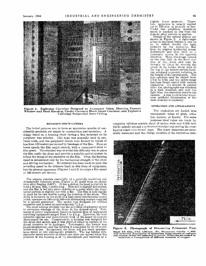
Figure 5. Photograph af Detonating Primacord Fuse Super XX film f15.6 0.10-mm. sllt. Detonation velocity = 6950 rnetere/eecond. bropaiation of detonation along column of explosive and motion of film are indioated by arrow^. Striations ara caused b p
variations in transpareno7 of+ dSfferen% de-nte of wrapper.
Vol. 36, No. 1 82 I N D U S T R I A L A N D E N G I N E E R I N G C H E M I S T R Y
fully controlled. I n general, glass was used only with liquids. The charges may be fired by the action of a short length of penta- erythritol tetranitrate detonating fuse (Primacord) which, in turn, is detonated by an electric blasting cap. The assembly except for the cap is shown in various sizes in Figure 3. The explosive charge is located 100 to 200 cm. from the camera lens, protected by a safety glass window. The window needs to be replaced only occasionally unless the charges are fired close to it.
Since the detonation reactions are so rapid, there is no neces- sity to hold the explosive charges h l y in place; they can be suspended in mid-air, by cords or wire, with proper precautions for alignment with the camera (Figure 4). Evidence of the ex- treme rapidity of the detonation reactions is shown by the photograph of the detonation of Primacord fuse in Figure 5. The alternating transparent and nontransparent strands of the wrapper are clearly visible in the light developed by the detona- tion itself. Evidently the detonation was substantially complete before the wrapper was disrupted.
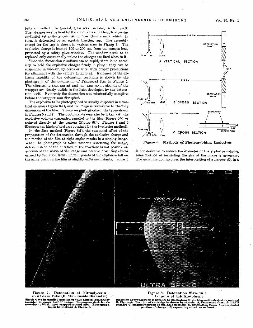
The explosive to be photographed is usually disposed in a ver- tical column (Figure 6A) , and its image is transverse to the long dimension of the film. This gives photographs of the types shown in Figures 5 and 7. The photographs may also be taken with the explosive column suspended parallel to the film (Figure 6B) or pointed directly at the camera (Figure 6C). Figures 8 and 9 illustrate the kinds of pictures obtained by the two latter methods.
In the first method (Figure 6A) , the combined effect of the propagation of the detonation through the explosive charge and the motion of the film at right angles results in a sloping image. When the photograph is taken without restricting the image, determination of the duration of the reactions is not possible on account of the width of the image and because obscuring effects caused by radiation from different points of the explosive fall on fhe same point on the film a t slightly different instants. Since i t
DETONATION
FILM+ ]lliu. 1 s B. CROSS SECTION
U
FILM JIT ' 0.10 MM. L E N S
Z I O C M . .-I, /A .c-
DETONATION c* CROSS SECTION
Figure 6. Methods of Photographing Explosives
is not desirable to reduce the diameter of the explosive column, some method of restricting the size of the image is necessary. The usual method involves the interposition of a narrow slit in a
Figure 7. Detonation of Nitroglycerin Figure 8. Detonation Wave in a in a Glass Tube (10 Mm. Inside Diameter) Column of Trinitrotoluene
Shock wave in d l l e d portion of tube caumed luminosity recorded in upper half of image. Transveree dark band. were due to black tapes wrapped around tube. Photograph
taken by method A. Figure 6.
Direction of propagation ie parallel to the motion of the film ae illustrated by method B, Figure 6. Position of cartridge is shown by sketch: A Primacord fuse; B, PETN primer; C, original position of exploded pertion; D, detdation wave; E, unexploded
portion of oharge; F, expanding shock wave front.
January, 1944 I N D U S T R I A L A N D E N G I N E E R I N G C H E M I S T R Y a3
focal plane. Jones (10) and Parisot (113 placed a slit composed of heavy-metal jaws fairly close to the explosive charge. This method has the disadvantage of obscuring the photograph with extraneous radiation caused by collision of the shock wave from the explosive with the jaws of the slit; furthermore, powerful explosives will seriously distort any metal objects placed only a few centimeters away. The alternative was to place the slit as close as possible to the film surface. The jaws of the slit were two Shick razor blades, spaced accurately 0.1 mm. apart and soldered to a brass frame which was supported from the top of the housing between the lens and the prism. This frame could also be moved along slots in order to adjust the slit as close as possible to the film. Actually, the clearance amounted to about 1 mm., which caused a widening of the image to abowt 0.5 mm. whcn the lens was wide open but permitted an image width of 0.2 mm. at an aperture of f/8 or less. Thus, the resolving time of the camera-that is, the time required for the film to travel a distance equal to the width of the slit-was approximately one microsecond.
The applications of this camera to high-explosive research have been manifold. The higher recording speed has permitted more accurate determinations of detonation velocities than is possible with the older types of apparatus, especially over short lengths of explosive and for those with very high velocities. Thus, the deviations from a uniform velocity caused by the effects of the initiating charge, or by nonuniformity of charge density and other similar details are more readily determined. It was hoped that a more accurate determination of the duration of detonation would be possible. However, i t was found that the luminosity associated with the initial intense development of energy endured for a time interval of substantially less than a microsecond, possibly 0.3 to 0.4 microsecond in the case of single explosive compounds such as nitroglycerin and trinitrotoluene. The detonation of such explosives appeared as shown in Figure 7. Nitroglycerin fired in a glass tube is characterized by a very bright line corresponding to the detonation zone, the width of which was hardly wider than the stationary image of the slit on the film. This was followed by a dark band indicating the ab- sence of an appreciable amount of radiation for a period of several microseconds, while the glass tube was being shattered, and then another luminous zone indicative of afterburning in the explosive
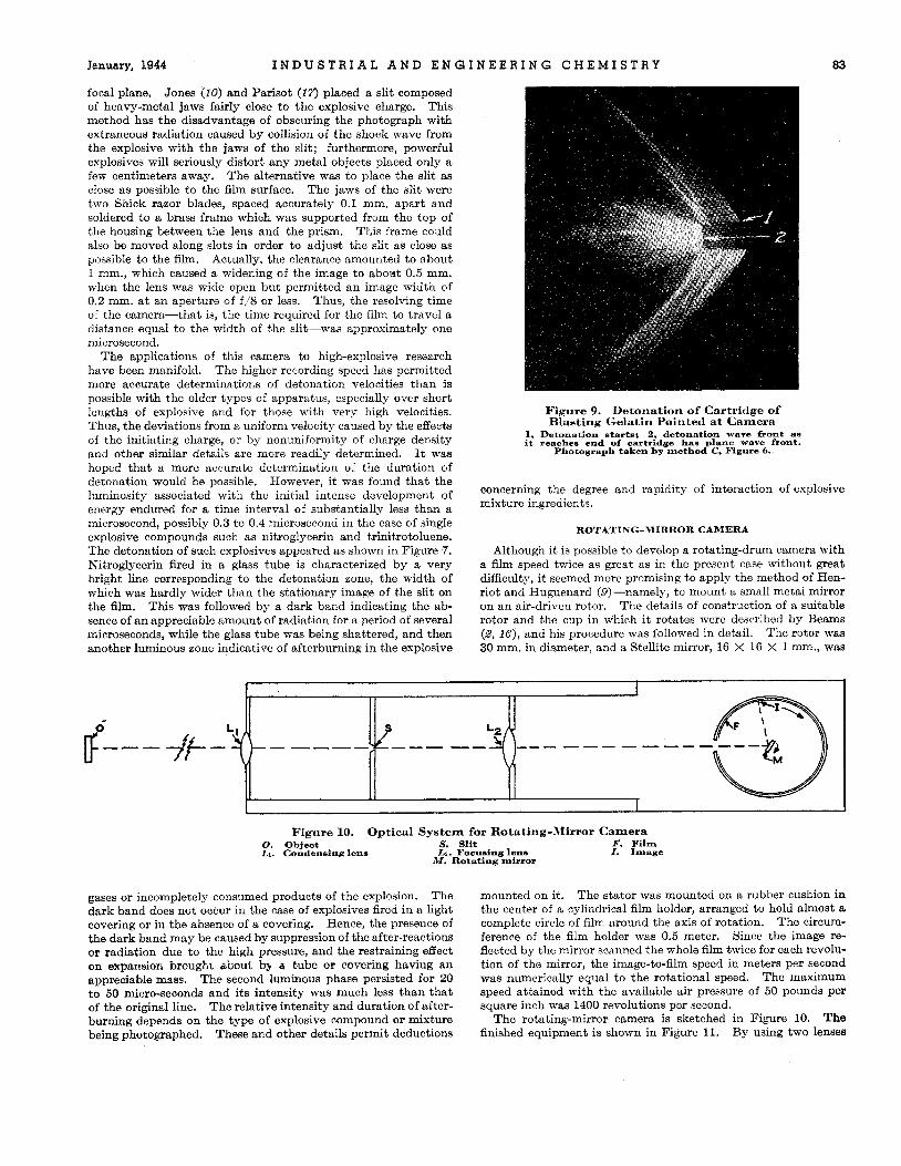
Figure 9. Blasting Gelatin Pointed at Camera
Detonation of Cartridge of
1, Detonation starts; 2 detonation wave front as it reaches end of cartridge has plane wave front.
Photograph taken by method C, Figure 6.
concerning the degree and rapidity of interaction of explosive mixture ingredients.
ROTATING-MIRROR CAMERA
Although it is possible to develop a rotating-drum camera with a film speed twice as great as in the present case without great difficulty, it seemed more promising to apply the method of Hen- riot and Huguenard (@-namely, to mount a small metal mirror on an air-driven rotor. The details of construction of a suitable rotor and the cup in which it rotates were described by Beams (8, 16), and his procedure was followed in detail. The rotor was 30 mm. in diameter, and a Stellite mirror, 16 X 16 X 1 mm., was
Figure 10. Optical System for Rotating-Mirror Camera 0. Object S. Slit F. Film Li. Condensing lens L,. Focusing lens I . Image
M . Rotating mirror
gases or incompletely consumed products of the explosion. The dark band does not occur in the case of explosives fired in a light covering or in the absence of a covering. Hence, the presence of the dark band may be caused by suppression of the after-reactions or radiation due to the high pressure, and the restraining effect on expansion broughi about b3 B tube or covering having an appreciable mass. The second luminous phase persisted for 20 to 50 micro-seconds and its intensity was much less than that of the original line. The relative intensity and duration of after- burning depends on the type of explosive compound or mixture being photographed. These and other details permit deductions
mounted on it. The stator was mounted on a rubber cushion in the center of a cylindrical film holder, arranged to hold almost a complete circle of film around the axis of rotation. The circum- ference of the film holder was 0.5 meter. Since the image re- flected by the mirror scanned the whole film twice for each revolu- tion of the mirror, the image-to-film speed in meters per second was numerically equal to the rotational speed. The maximum speed attained with the available air pressure of 50 pounds per square inch was 1400 revolutions per second.
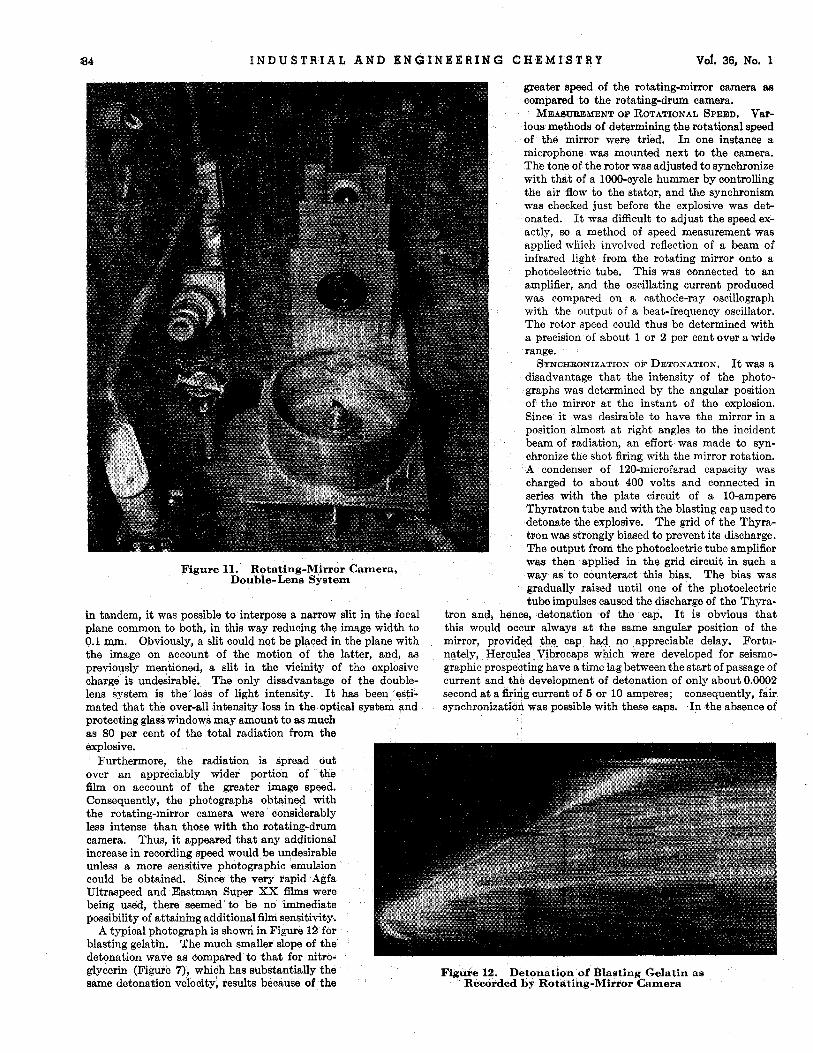
The finished equipment is shown in Figure 11. By using two lenses
The rotating-mirror camera is sketched in Figure 10.
8 4 I N D U S T R I A L A N D E N G I N E E R I N G C H E M I S T R Y Vof. 36, No. 1
Figure 11. Rotating-Mirror Camera, Double-Lens System
in tandem, it was possible to interpose a narrow slit in the focal plane common to both, in this way reducing the image width to 0.1 mm. Obviously, a slit could not be placed in the plane with the image on account of the motion of the latter, and, as previously mentioned, a slit in the vicinity of the explosive charge is undesirable. The only disadvantage of the double- lens system is the loss of light intensity. It has been esti- mated that the over-all intensity loss in the optical system and protecting glass windows may amount to as much as 80 per cent of the total radiation from the explosive.
Furthermore, the radiation is spread out over an appreciably wider portion of the film on account of the greater image speed. Consequently, the photographs obtained with the rotating-mirror camera were considerably less intense than those with the rotating-drum camera. Thus, it appeared that any additional increase in recording speed would be undesirable unless a more sensitive photographic emulsion could be obtained. Since the very rapid Agfa Ultraspeed and Eastman Super XX films were being used, there seemed to be no immediate possibility of attaining additional film sensitivity.
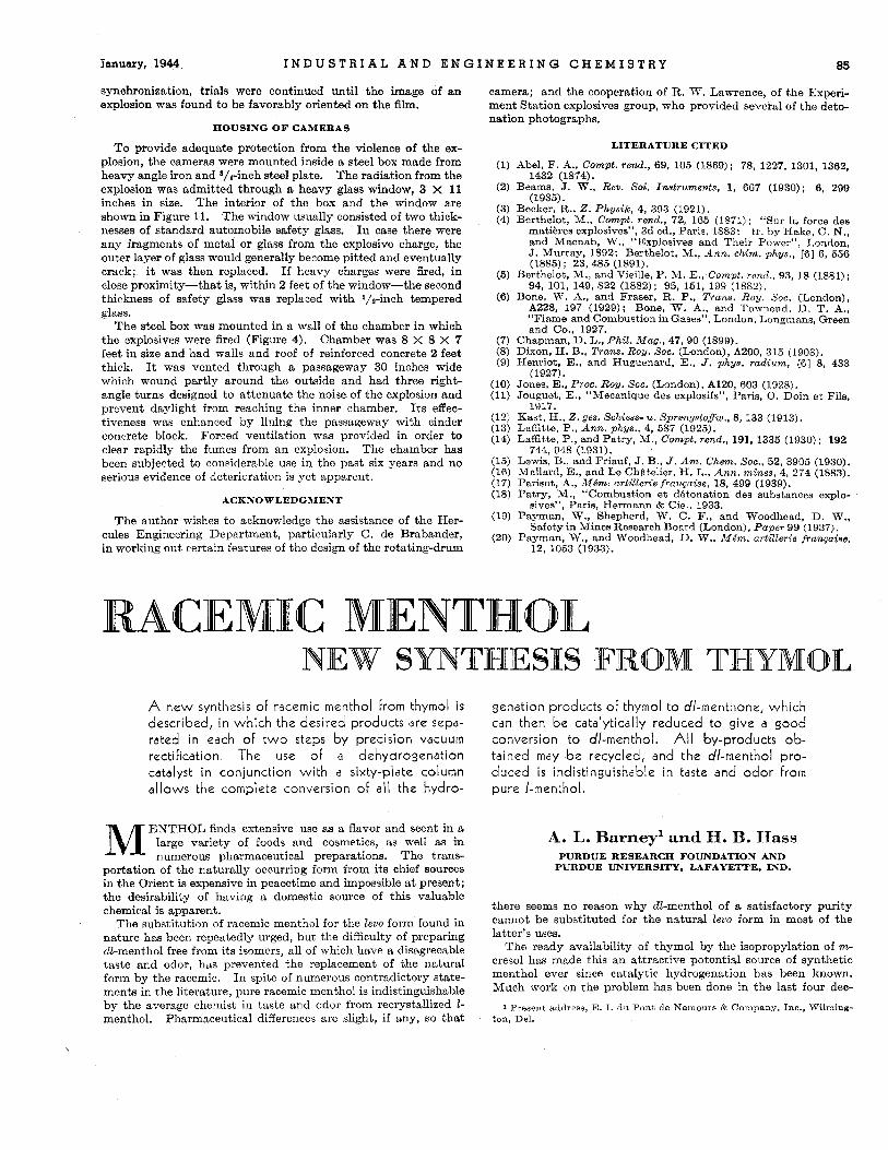
A typical photograph is shown in Figure 12 for blasting gelatin. The much smaller slope of the detonation wave as compared to that for nitro- glycerin (Figure 7), which has substantially the same detonation velocity, results because of the
greater speed of the rotating-mirror camera a8 compared to the rotating-drum camera.
MEASUREMENT OF ROTATIONAL SPEED. Var- ious methods of determining the rotational speed of the mirror were tried. In one instance a microphone was mounted next to the camera. The tone of the rotor was adjusted to synchronize with that of a 1000-cycle hummer by controlling the air flow to the statqr, and the synchronism was checked just before the explosive was det- onated. It was difficult to adjust the speed ex- actly, so a method of speed measurement was applied wliich involved reflection of a beam of infrared light from the rotating mirror onto a photoelectric tube. This was connected to an amplifier, and the oscillating current produced was compared on a cathode-ray oscillograph with the output of a beat-frequency oscillator. The rotor speed could thus be determined with a precision of about 1 or 2 per cent over a wide range.
It was a disadvantage that the intensity of the photo- graphs was determined by the angular position of the mirror a t the instant of the explosion. Since i t was desirable to have the mirror in a position almost a t right angles to the incident beam of radiation, an effort was made to syn- chronize the shot firing with the mirror rotation. A condenser of 120-microfarad capacity was charged to about 400 volts and connected in series with the plate circuit of a 10-ampere Thyratron tube and with the blasting cap used to detonate the explosive. The grid of the Thyra- tron was strongly biased to prevent its discharge. The output from the photoelectric tube amplifier was then applied in the grid circuit in such a way as to counteract this bias. The bias was gradually raised until one of the photoelectric tube impulses caused the discharge of the Thyra-
SYNCHRONIZATION OF DETONATION.
tron and, hence, detonation of the cap. It is obvious that this would occur always a t the same angular position of the mirror, provided the cap had no appreciable delay. Fortu- nately, Hercules Vibrocaps which were developed for seismo- graphic prospedting have a time lag between the start of passage of current and the development of detonation of only about 0.0002 second a t a &ing current of 5 or 10 amperes; consequently, fair synchronization was possible with these caps. In the absence of
Figure 12. Detonation of Blasting Gelat in as Redorded b y Rotating-Mirror Camera
January, 1944 I N D U S T R I A L A N D E N G I N E E R I N G C H E M I S T R Y 85
synchronization, trials were continued until the image of an explosion was found to be favorably oriented on the film.
HOUSING O F CAMERAS
To provide adequate protection from the violence of the ex- plosion, the cameras were mounted inside a steel box made from heavy angle iron and s/,-inch steel plate. The radiation from the explosion was admitted through a heavy glass window, 3 X 11 inches in size. The interior of the box and the window are shown in Figure 11. The window usually consisted of two thick- nesses of standard automobile safety glass. I n case there were any fragments of metal or glass from the explosive charge, the outer layer of glass would generally become pitted and eventually crack; it was then replaced. If heavy charges were fired, in close proximity-that is, within 2 feet of the window-the second thickness of safety glass was replaced with ‘/*-inch tempered glass.
The steel box was mounted in a wall of the chamber in which the explosives were fired (Figure 4). Chamber was 8 X 8 X 7 feet in size and had walls and roof of reinforced concrete 2 feet thick. It was vented through a passageway 30 inches wide which wound partly around the outside and had three right- angle turns designed to attenuate the noise of the explosion and prevent daylight from reaching the inner chamber. I t s effec- tiveness was enhanced by lining the passageway with cinder concrete block. Forced ventilation was provided in order to clear rapidly the fumes from an explosion. The chamber has been subjected to considerable use in the past six years and no serious evidence of deterioration is yet apparent.
ACKNOWLEDGMENT
The author wishes to acknowledge the assistance of the Her- cules Engineering Department, particularly C. de Brabander, in working out certain features of the design of the rotating-drum
camera; and the cooperation of R. W. Lawrence, of the Experi- ment Station explosives group, who provided several of the deto- nation photographs.
LITERATURE CITED
Abel. F. A., Compt. rend., 69, 105 (1869); 78, 1227, 1301, 1362,
Beams, J. W., Rev. SCi. Instruments, 1, 667 (1930); 6, 299 1432 (1874).
( 1 R3.9. Bs’ckei;’R., 2. Physiic, 4, 393 (1921). Berthelot, M., Contpt. rad., 72, 165 (1871); “Sur la force des
matihres explosives”, 3d ed., Paris, 1883; tr. by Hake, C. N., and Macnab. W., “Explosives and Their Power”, London, J. Murray, 1892; Berthelot, M., Ann. chim. phys., [SI 6, 556 (1885); 23, 485 (1891).
Berthelot, M., and Vieille, P. M. E., Compt. rend., 93, 18 (1881); 94, 101, 149, 822 (1882); 95, 151, 199 (1882).
Bone, W. A., and Fraser, R. P., Trans. R o y . Soc. (London), A228, 197 (1929); Bone, W. A., and Townend. D. T. A., “Flame and Combustion in Gases”, London. Longmans. Green and Co., 1927.
Chapman, D. L., P h
JoAes, E., Proc. Roy. SOC. (London), A120, 603 (1928). Jouguet, E., “Mecanique des explosifs”, Paris, 0. Doin et Fils,
Kast, H., 2. ges. Schiws- u. Sprengstoffw., 8, 133 (1913). Laffitte. P.. Ann. vhws.. 4. 687 (1925).
1917.
Laffitte; P., and Pat&, ‘M:, Compt. re’nd., 191, 1335 (1930) : 192 744. 948 (1931).
Lewis, B., and Friauf, J. B., J . Am. Chem. Soc., 52, 3905 (1930). Mallard, E., and Le ChPtelier, H. L., Ann. mines, 4, 274 (1883). Parisot, A,, Mdm. arlillerie franpaise, 18, 499 (1939). Patry, M., “Combustion et detonation des substanoes explo-
sives”, Paris, Hermann & Cie., 1933. Payman, W., Shepherd, W. C. F., and Woodhead, D. W.,
Safety in Mines Research Board (London), Paper 99 (1937). Payman, W., and Woodhead, D. W., Mdm. artillerie franpaise, 12, 1063 (1933).
A new synthesis of racemic menthol from thymol i s described, in which the desired products are sepa- rated in each of t w o steps by precision vacuum rectification. The use of a dehydrogenation cdtalyst in conjunction wi th a sixty-plate column allows the complete conversion of all the hydro-
M ENTHOL finds extensive use as a flavor and scent in B
large variety of foods and cosmetics, as well as in numerous pharmaceutical preparations. The trans-
portation of the naturally occurring form from its chief sources in the Orient is expensive in peacetime and impossible a t present; the desirability of having a domestic source of this valuable chemical is apparent.
The substitution of racemic menthol for the Eevo form found in nature has been repeatedly urged, but the difficulty of preparing dl-menthol free from its isomers, all of which have a disagreeable taste and odor, hrbs prevented the replacement of the natural form by the racemic. In spite of numerous contradictory state- ments in the literature, pure racemic menthol is indistinguishable by the average chemist in taste and odor from recrystallized Z- menthol. Pharmaceutical differences are slight, if any, so that
genation products OF thymol to dl-menthone, which can then be catalytically reduced to give a good conversion to dl-menthol. All by-products ob- tained may be recycled, and the dl-menthol pro- duced i s indistinguishable in taste a n d odor From pure /-menthol.
A. L. Barney’ and M. B. Hass PURDUE RESEARCH FOUNDATION AND
PURDUE UNIVERSITY, LAFAYETTE, IND.
there seems no reason why dl-menthol of a satisfactory purity cannot be substituted for the natural levo form in most of the latter’s uses.
The ready availability of thymol by the isopropylation of m,- cresol has made this an attractive potential source of synthetic menthol ever since catalytic hydrogenation has been known. Much work on the problem has been done in the last four deo-
1 Present address, E. I. du Pont de Nemours & Company. Inc., Wilming- ton , Del.