Embed Size (px)
Citation preview
STUDY OF TWO-PHASE FLOW IN PIPE BENDS
by
I ~ I
JOSE RAMON CASTILLO ~
B. S., Agricultural and Mechanical College of Texas(1956)
SUBMITTED IN PARTIAL FULFILLMEl\l'TOF THE REQUIREl\1ENTSFOR THE
DEGREE OF MASTER OFSCIENCEat the
MASSACHUSETTS INSTITUTE OF TECHNOLOGYJune. lQS7
Signature of AuthorDepa11tment of'Mecharrfcal EngineeringMay 'to. 1957
Certified by ___ ......-==-..0...-- ---.--_----.--
Thesis supervIsorAccepted by
chair~an," ~ep~rtm~n~al Comnlittee on GraduatestudelJts
A CKNOvlLEDGE ME NT
The author wishes to express his gratitude toProfessor Miguel A. Santalo for having devoted a greatdeal of his valuable time giving advice and encourage-ment during the development of this thesis.
The author is also grateful to Melvin Cohen forthe use of his experimental results.
STUDY OF TWO-PHASE FLOW IN PIPE BENDSby
JOSE RAMON CASTILLO
Submitted to the Department of Mechanical Engineering onMay 20, 1957, in partial fulfillment of the requirementsfor the degree of Master of Science.
ABSTRACT
An analysis has been made to determine the energy ofrotation, due to the difference in densities, of a gas-liquid mixture as it goes through a horizontal bend. Thisenergy, assumed dissipated due to frictional forces, hasbeen supposed to account for part of the pressure drop ofthe mixture during the passage.
Both gas and liquid have been considered incompressibleand the flow regimes analyzed have been separated andannular.
The flow has been assumed one dimensional along thepipe, and a one dimensional rotation has been superimposedin the bend.
The use of a rather large gas-liquid velocity ratiohas shown values of pressure drop a great deal below thosefound experimentally. Consideration of the limiting caseof equal velocity of gas and liquid yiel~values of pres-sure drop larger than experimental.
It has been concluded that although the energy dissi-pated during rotation must account for a great deal of thepressure drop, other phenomena taking place in the bendmust also be sources of pressure Lossee .
Thesis Supervisor: Miguel A. SantaloTitle: Assistant Professor of Mechanical Engineering
TABLE OF CONTENTS
List of IllustrationsTable of Significant SymbolsI. IntroductionII. Literature Review
II. 1. Theoretical vlork on Secondary Flo'Vl
II. 2. Experimental WorkIII. Dynamic Analysis of Separated Flow Through
a BendIII. 1. AssumptionsIII. 2. Mathematical AnalysisIII. 3. Approximate Solution
IV. Energy Loss EvaluationIV. 1. Pressure Drop Calculation for
Separated FlowIV. 2. Extension to Annular Flow
v.
IV. 3. A Method to Determine the Gas-LiquidVelocity Ratio
Experimental WorkV.I. ApparatusV. 2. Performance for water Onlyv. 3. Performance for Two-Phase Flow
VI. Discussion of ResultsAppendixBibliography
i
Pageiiiii'
1
4
4
11
1818192324
24
27
2936
3637
38
39
43
45
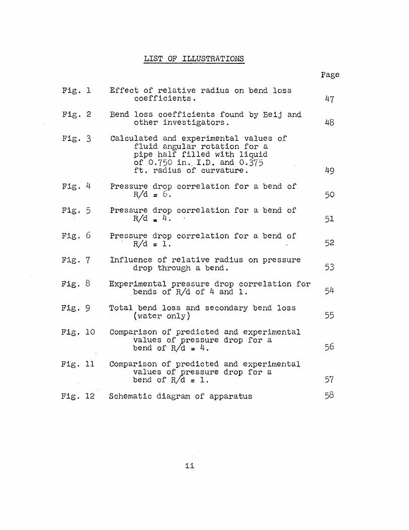
Fig. 1
Fig. 2
Fig. 3
Fig. 4
Fig. 5
Fig. 6
Fig. 7
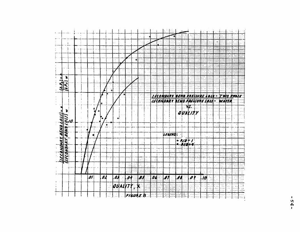
Fig. 8
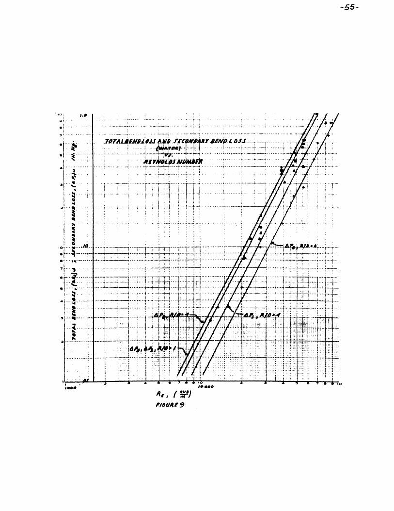
Fig. 9
Fig. 10
Fig. 11
Fig. 12
LIST OF ILLUSTRATIONS
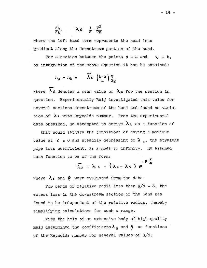
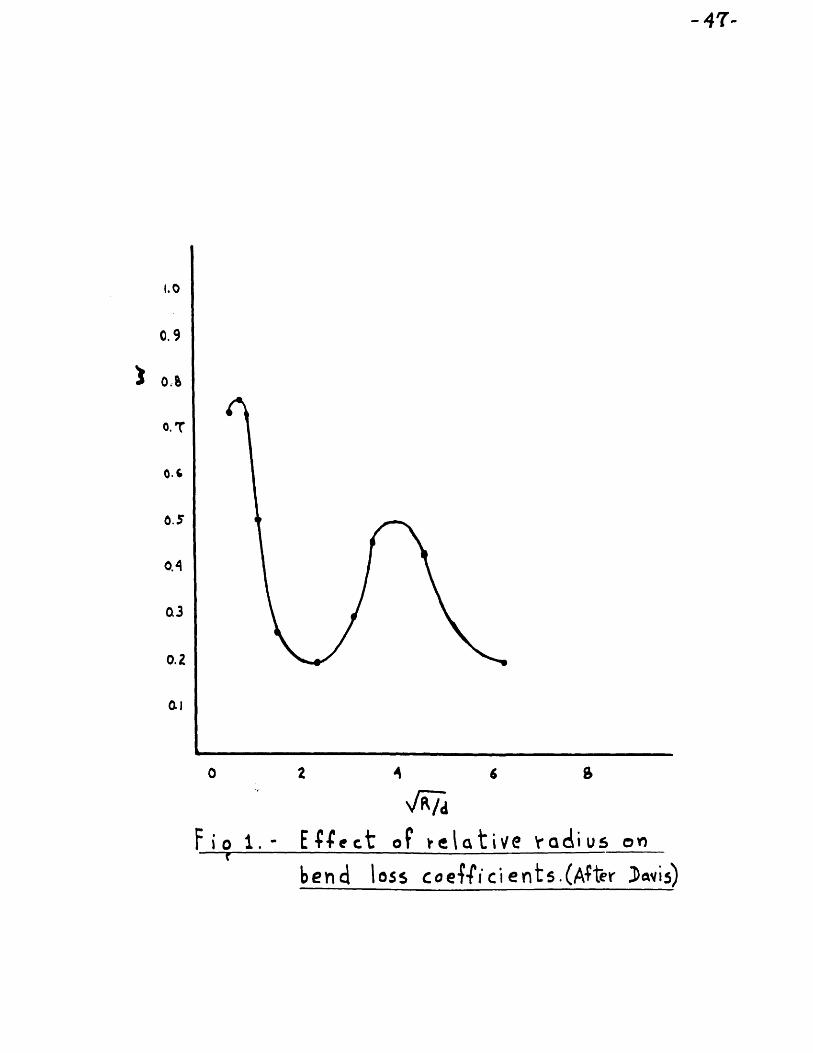
Effect of relative radius on bend losscoefficients.
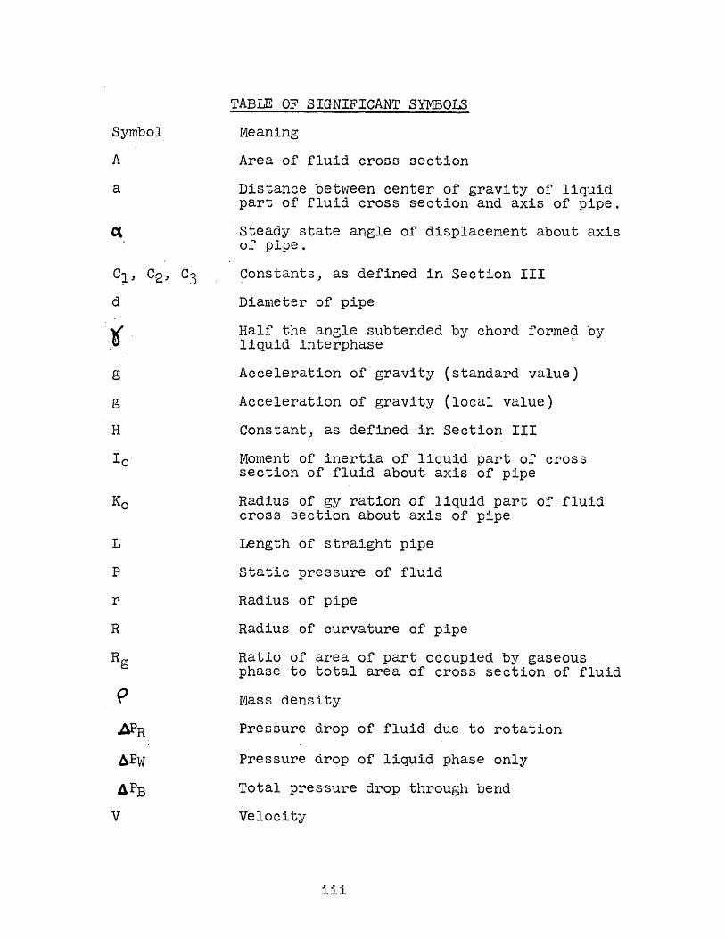
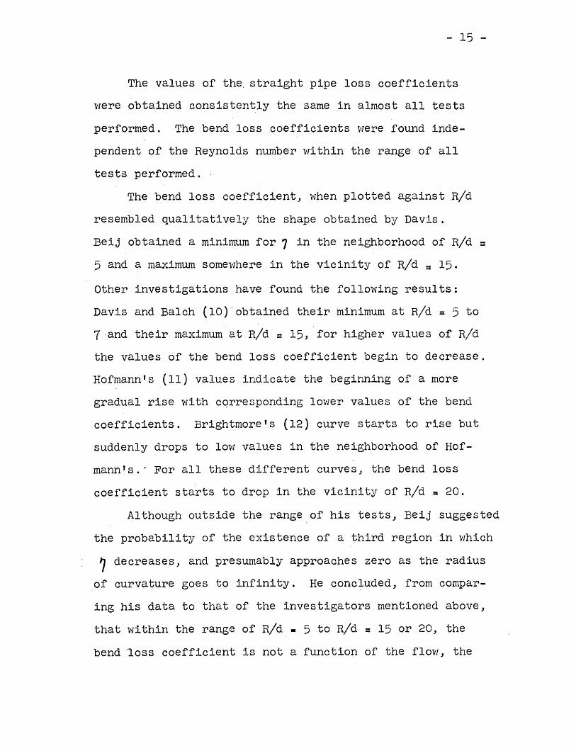
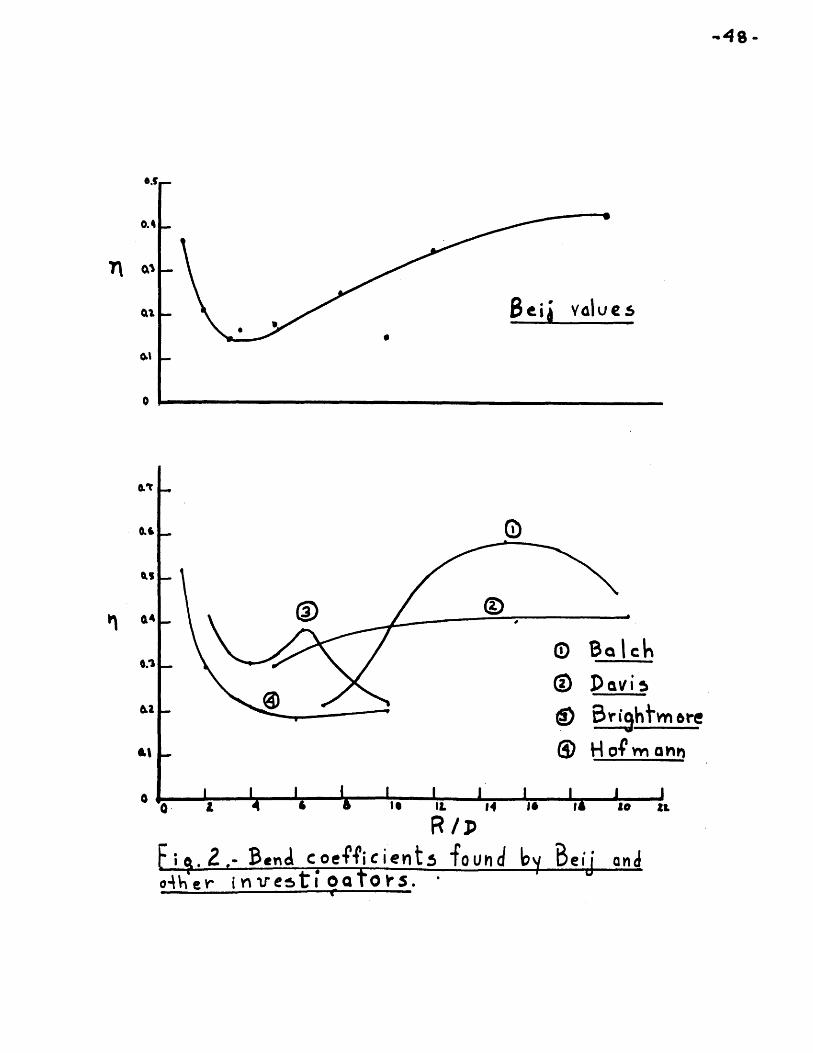
Bend loss coefficients found by Beij andother investigators.
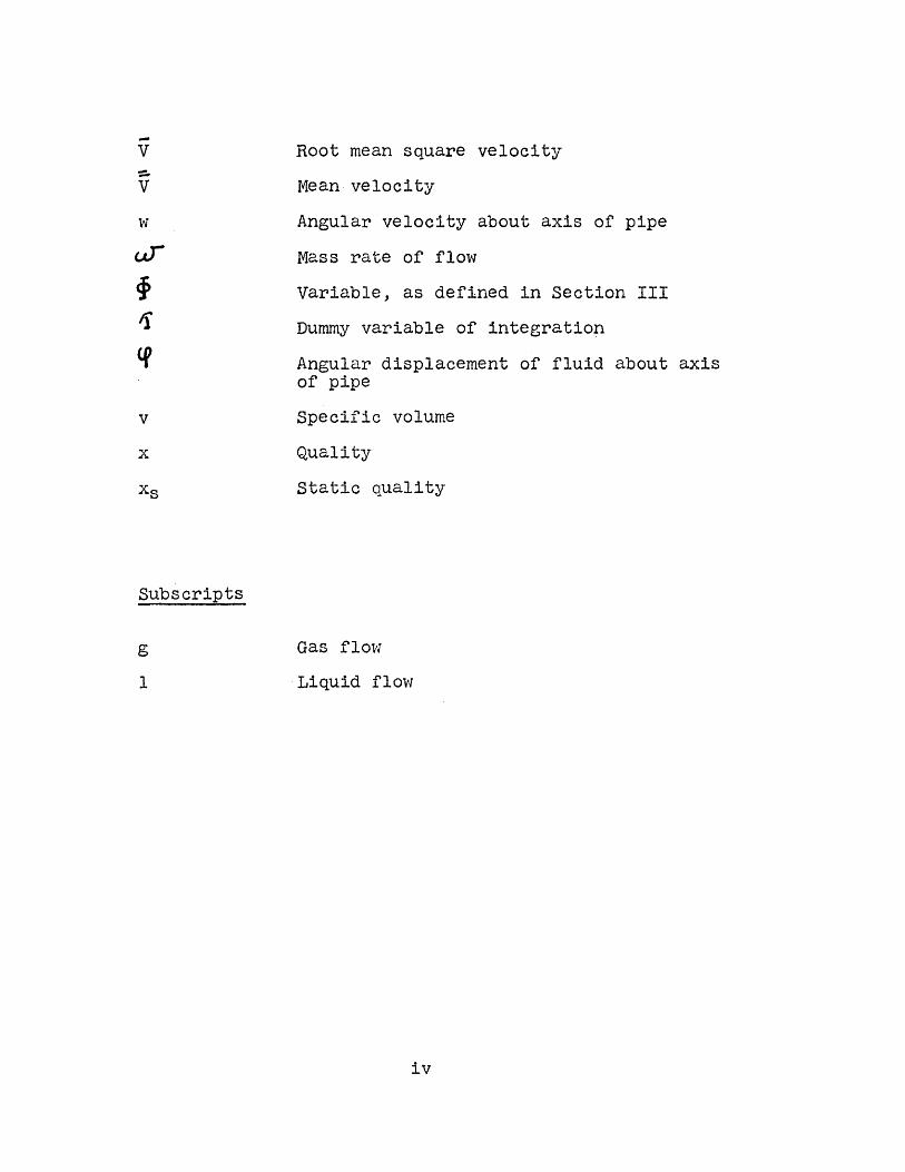
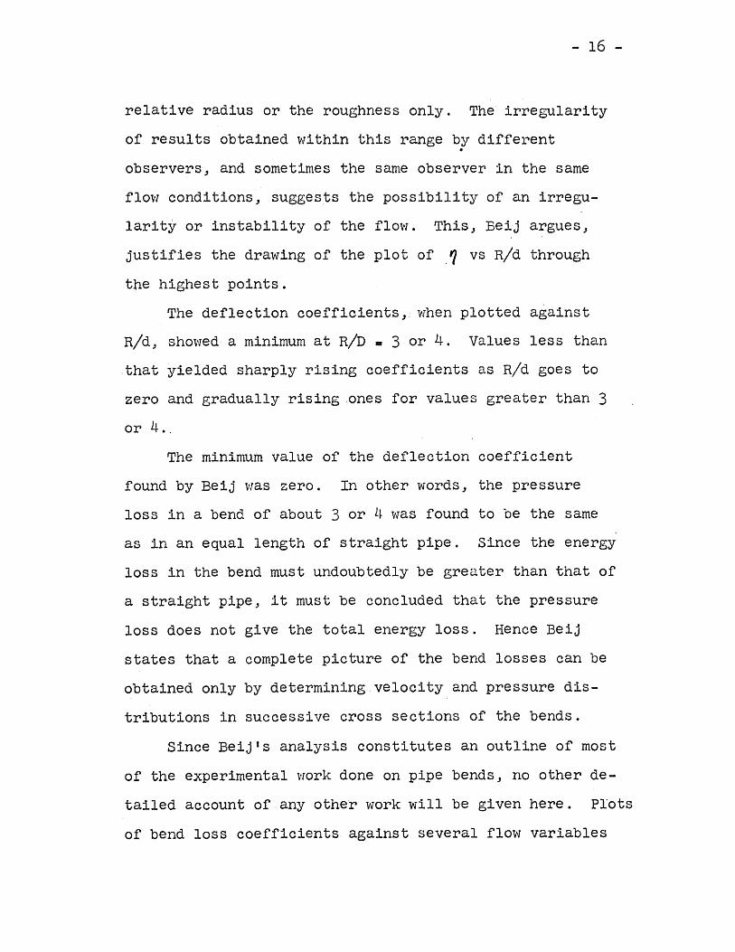
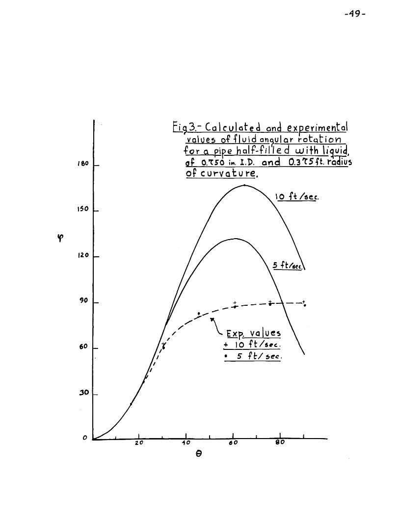
Calculated and experimental values offluid angular rotation for apipe half filled with liquidof 0.'T50 in., I.D. and 0.375ft. radius of curvature.
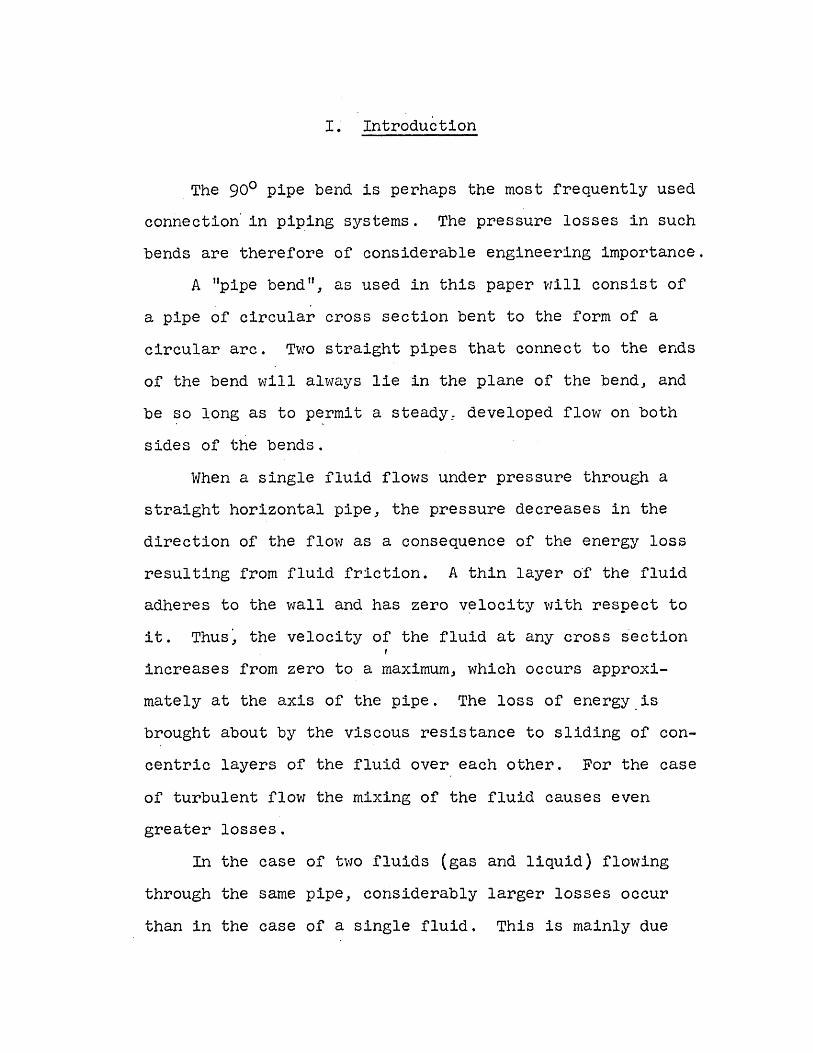
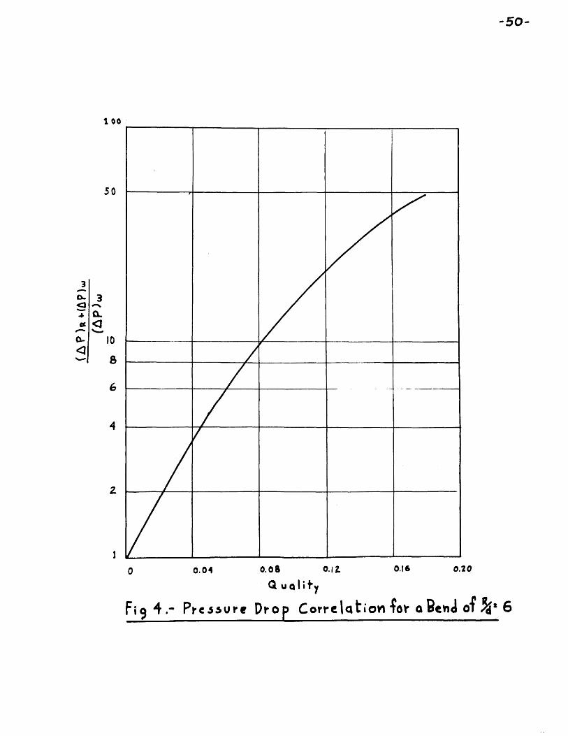
Pressure drop correlation for a bend ofRid = 6.
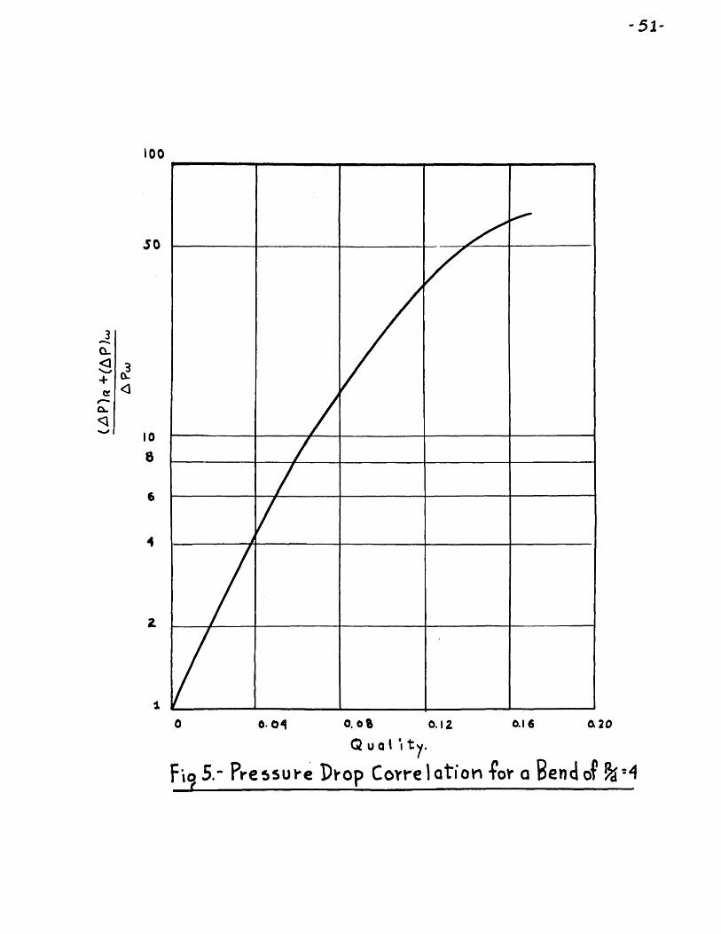
Pressure drop correlation for a bend ofRid. 4.
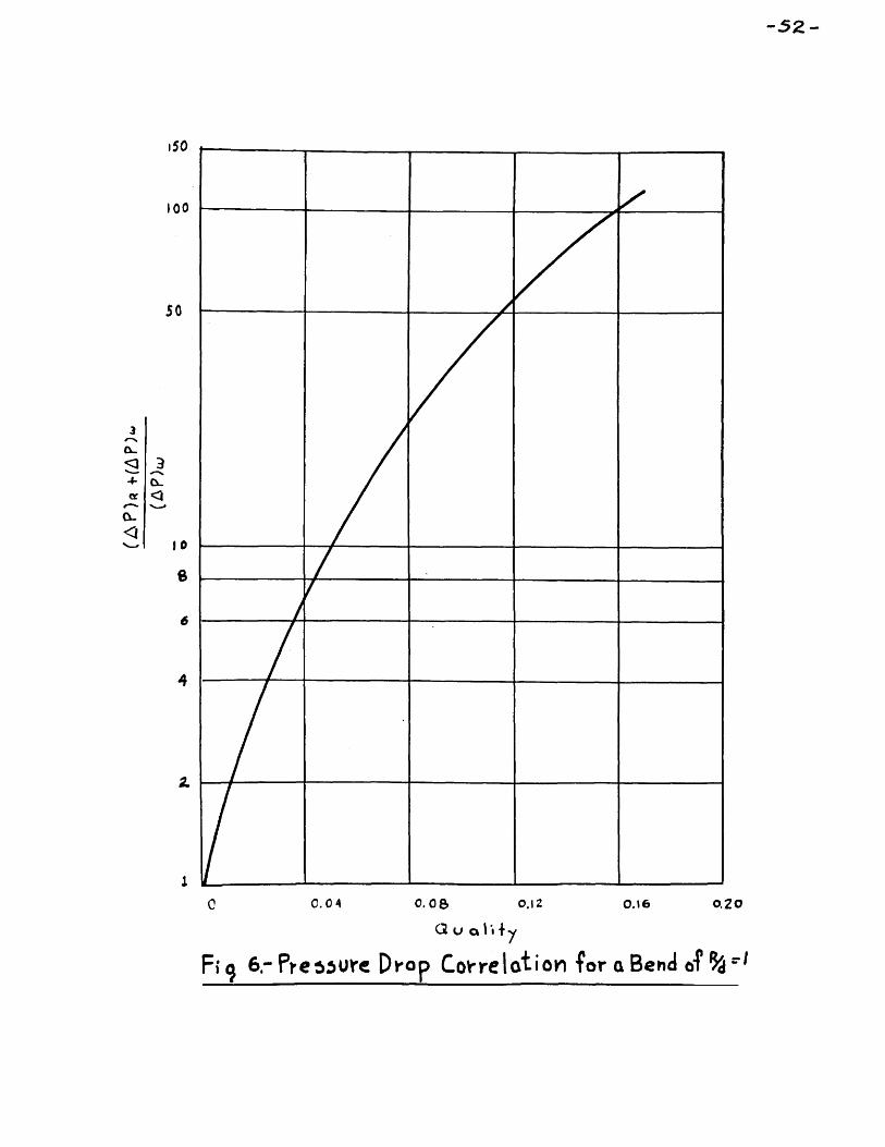
Pressure drop correlation for a bend ofRid = 1.
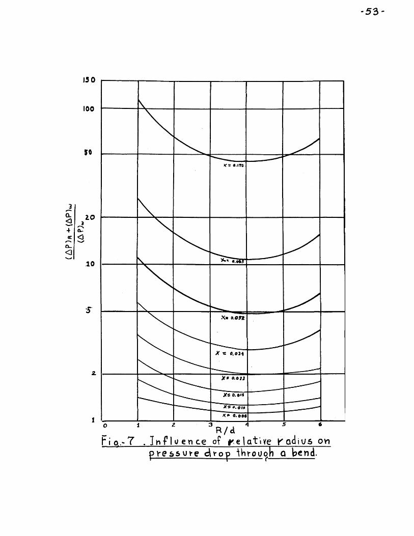
Influence of relative radius on pressuredrop through a bend.
Experimental pressure drop correlation forbends of Rid of 4 and 1.
Total bend loss and secondary bend loss(wa ter only)
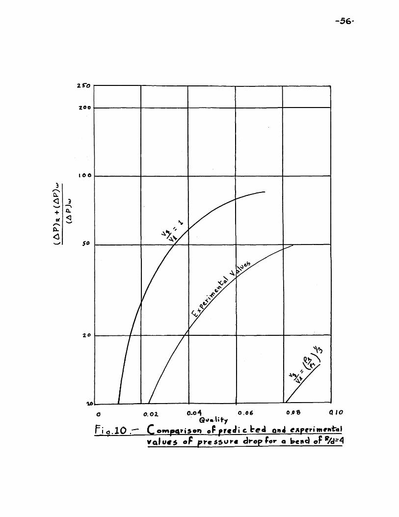
Comparison of predicted and experimentalvalues of ~ressure drop for abend of Rid = 4.
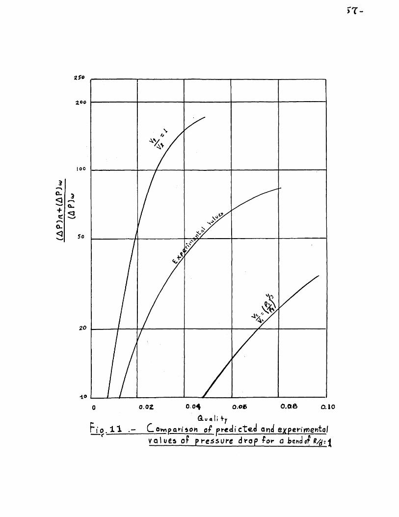
Comparison of predicted and experimentalvalues of ~ressure drop for abend of Rid = 1.
Schematic diagram of apparatus
ii
Page
47
48
49
50
51
52
53
54
55
56
57
58
SymbolA
a
ex
CI, C2, c3d
l(ggHIo'
Ko
L
p
rRRg
~
.APR6EW
APBV
TABLE OF SIGNIFICANT SYMBOLSMeaningArea of fluid cross sectionDistance between center of gravity of liquidpart of fluid cross section and axis of pipe.Steady state angle of displacement about axisof pipe.Constants, as defined in Section IIIDiameter of pipeHalf the angle subtended by chord formed byliquid interphaseAcceleration of gravity (standard value)Acceleration of gravity (local value)Constant, as defined in Section IIIMoment of inertia of liquid part of crosssection of fluid about axis of pipeRadius of gy ration of liquid part of fluidcross section about axis of pipeLength of straight pipeStatic pressure of fluidRadius of pipeRadius of curvature of pipeRatio of area of part occupied by gaseousphase to total area of cross section of fluidMass densityPressure drop of fluid due to rotationPressure drop of liquid phase onlyTotal pressure drop through bendVelocity
iii
vvw
v
x
Subscripts
g
1
Root mean square velocityMean velocityAngular velocity about axis of pipeMass rate of flowVariable, as defined in Section IIIDummy variable of integrationAngular displacement of fluid about axisof pipeSpecific volumeQualityStatic quality
Gas flow-Liquid flow
iv
I. Introduction
The 900 pipe bend is perhaps the most frequently usedconnection'in piping systems. The pressure losses in suchbends are therefore of considerable engineering importance.
A "pipe bend II, as used in this paper vIill consis t ofa pipe of circular cross section bent to the form of acircular arc. Two straight pipes that connect to the endsof the bend will always lie in the plane of the bend, andbe so long as to permit a steady: developed flow on bothsides of the bends.
When a single fluid flows under pressure through astraight horizontal pipe, the pressure decreases in thedirection of the flow as a consequence of the energy lossresulting from fluid friction. A thin layer o~ the fluidadheres to the wall and has zero v~locity with respect toit. Thus~ the velocity of the fluid at any cross sectionincreases from zero to a maximum, which occurs approxi-mately at the axis of the pipe. The loss of energy.isbrought about by the viscous resistance to sliding of con-centric layers of the fluid over each other. For the caseof turbulent flow the mixing of the fluid causes evengreater losses.
In the case of two fluids (gas and liquid) flowingthrough the same pipe, considerably larger losses occurthan in the case of a single fluid. This is mainly due
- 2 -
to the fact that, in general, the liquid and gaseousphases flow at different velocities, and account has tobe taken of friction at the interphase and mass transferbetween the liquid and the gas.
In going through a bend, a single fluid experiencesa circulatory motion perpendicular to the direction ofthe flow. This motion is due to the non-uniform velocityof the fluid as it approaches the bend. It alters thecharacter of the flow and causes a loss of energy inaddition to that of friction. In the case of two fluidsof different density going through a bend one additionalaspect has to be considered since centrifugal accelera-tion causes the heavier fluid to flow towards the outer"Tall. The case of air and wat.er as the two fluids hasbeen considered numerically.
If the flow is assumed to be separated* and thevelocity uniform at the entrance of the bend, this motioncan be idealized as a pure rotation imposed on the mainflow.
The purpose of this thesis has been to determine theenergy loss due to such motion and its correlation to theeasily accessible flow variables.
The ,total energy loss of tne bend has been assumedto be the energy loss due to the above mentioned rotation,
*See Section III for definition of term
- 3 -
plus the energy loss that would have taken place due tosecondary flow·within each separate phase.
The pressure drop associated with this energy ofrotation has been computed for the liquid phase andassumed to be equal to the pressure drop of the mixture.
A non-dimensional plot of the energy loss throughthe bend) less frictional effects) has been made and com-pared with similar plots for experimental data obtainedby Me1yin Cohen in a yet unpublished wor-k,
II. Literature Review
- 4 -
The bulk of "all the available literature on pressuredrop through bends can be classified into two groups:analysis of secondary flow in the bend and investigationof its relation to the energy loss by the fluid in goingthrough it, and finally, experimental work aimed to findIIbendloss" coefficients.
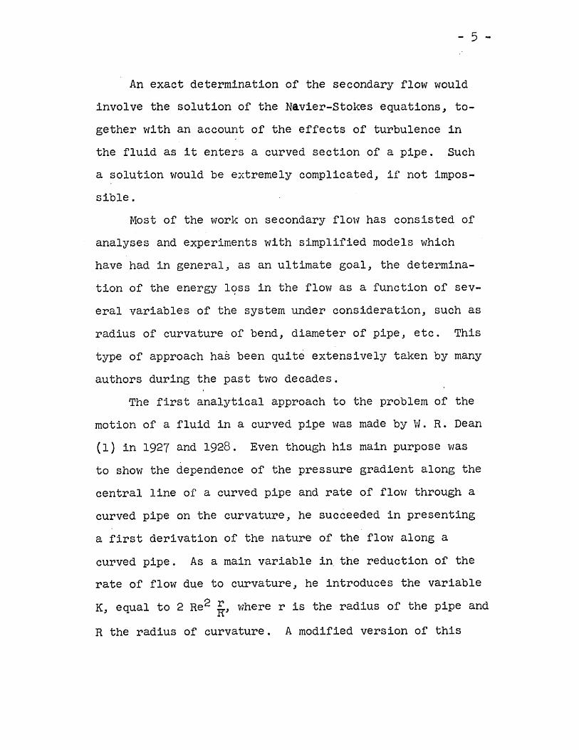
II. 1. Theoretical Work on Secondary FlowSecondary flow occurs in curved pipes. This flow re-
sults from the fact that the fluid near the center of thecross section is moving at a higher velocity than at thesides due to the retarding effect of friction. This dif-ference in velocities produces an outward flow in the cen-tral plane of the bend and a corresponding inward flow ateach side due to greater centrifugal force on the fastermoving liquid. (See"sketch below)
Secondary flow formation in a bend
- 5 -
An exact determination of the secondary flow wouldinvolve the solution of the Navier-Stokes equations, to-gether with an account of the effects of turbulence inthe fluid as it enters a curved section of a pipe. Sucha solution would be extremely complicated, if not impos-sible.
Most of the work on secondary flow has consisted ofanalyses and experiments with simplified models whichhave had in general, as an ultimate goal, the determina-tion of the energy 19ss in the flow as a function of sev-eral variables of the system under consideration, such asradius of curvature of bend, diameter of pipe, etc. Thistype of approach has been quite extensively taken by manyauthors during the past two decades.
The first analytical approach to the problem of themotion of a fluid in a curved pipe was made by W. R. Dean(1) in 1927 and 1928. Even though his main purpose wasto show the dependence of the pressure gradient along thecentral line of a curved pipe and rate of flow through acurved pipe on the curvature, he succeeded in presentinga first derivation of the nature of the flow along acurved pipe. As a main variable in the reduction of therate of flow due to curvature, he introduces the variableK, equal to 2 Re2 kJ wher-e r is the radius of the pipe andR the radius of curvature. A modified version of this
- 6 -
variable 1s commonly known as Deants number:1/2 Re Vr/R = D.
Dean's analysis is confined to laminar flow in curvedpipes of large bend ~adius as compared to the diameter ofthe p~pe. The equations of motion obtained under theseassumptions are solved by an expansion about the Reynoldsnumber and restricted to values of it of 500 or less.Although his equations are limited and complex, and there-fore represent little progress towards the derivation of ageneral theoret~cal expression for the flow in bends, hiswork paved the way for further investigations in the field.
His conclusions also became a great step in the studyof secondary flow. He successfully explained the mannerin which two symmetrical circulations are set up in thebend. Other investigations have come into a very closeagreement with this result. He also comes to the conclu-sion that the most interesting effect of the curvature onthe flow is that, in a curved pipe, part of the fluid iscontinually oscillating between the central part of thepipe, where the velocity is high, and the neighborhood ofthe boundary, where the velocity is low. This motion, dueto the centrifugal force acting upon the fluid, causes aloss of energy that has no counterpart in a streamlinemotion through a straight pipe. Furthermore, turbulenceis accompanied by a lateral movement of the fluid, which
- 7 -
also implies a loss of energy with no counterpart insteady motion.
Following Dean, several solutions have been obtainedby making further simplifying assumptions in order tolinearize his equations of motion.
In measurements carried out by Adler (2) for valuesof R/r equal to 50, 100 and 200, he demonstrated theexistence of a large increase in the resistance of theflow due to curvature for Re V r/R > 10,·l. According tohis calculations he is able to define a coefficient ofresistance for a curved pipe given as:
= 0.1064 lRe "r /R ] 1/2
where Ao denotes the resistance of a straight pipe.fJIeasurementshave indicated, however, that the above equa-tion is only valid for values of the parameter Re VrVR inexcess of 102.8. Later on, Prandtl (3) came out with anempirical formula which expressed Adler's results to a
higher degree of precision:
-- -r'\ o. 3 E>O.3r-r y\
in the range:2D = Re V:r-/R ~ 103. °
In 1949, Squire and Winte~(4) showed that the sec-ondary flow through a bend could occur as a result of the
- 8 -
non-uniform velocity profile of the fluid at the entranceof the bend. They suggested that a more general investiga-tion to the rotational flow of a newtonian fluid in threedimensions could be made if attention was concentrated inthe component of the vorticity the direction of the flow.
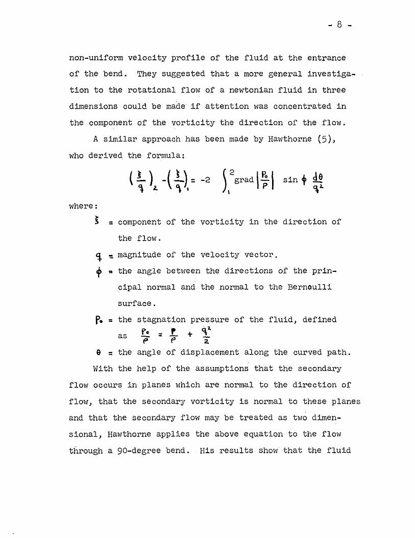
A similar approach has been made by Hawthorne (5),
who derived the formula:
(!..) -(1.) = -2~ z: '\.
sin + M<:\1.
where:~ = component of the vorticity in the direction of
the flow.~ ~ magnitude of the velocity vector.+ = the angle between the directions of the prin-
cipal normal and the normal to the Bernoullisurface.
p. = theas
stagnation pressure of the fluid, defined"2-
~=.!.+~P f' 2.
angle of displacement along the curved path.e = theWith the help of the assumptions that the secondary
flow occurs in planes which are normal to the direction offlow, that the secondary vorticity is normal to these planesand that the secondary flow may be treated as two dimen-sional, Hawthorne applies the above equation to the flowthrough a 90-degree bend. His results show that the fluid
... 9 -
in the bend will oscillate between the angles of ° and~with a period for a complete oscillation approximatelyequal to 2~;VR/d radians of turn.
This fact may perhaps be an explanation to Davis'results, who in 1910, in an attempt to plot bend losscoefficients ~ against~R/d found an almost periodicvar-Latrf.onof ) with ~ R/d. (See Figure 1).
Eichemberger (7) conducted investigations usingHawthorne's ~nalysis. These experiments show that vis-cosity is of little influence for the phenomenon of·secondary flow. He suggested the idea that viscousphenomena within the bend are of secondary importanceand one therefore might suspect that the dissipation dueto viscosity is not essentially higher in a bend than ina straight pipe.
His results' a~so seem to show that the Kineticenergy contained i~ the secondary flow is small. He sug-gested that the main losses ~n the passage through abend are not due to the dissipation of secondary veloci-ties but to the displaced boundary of fluid.
rrc~ riumbers, he attributes approximately one half ofthe total loss through a bend to dissipation within thebend itself, out of which approximately one fifth is dueto secondary rotation. The other half is considered lostin the downstream tangent of the bend, due to the turbulenceinduced by the change in velocity profile.
- 10 -
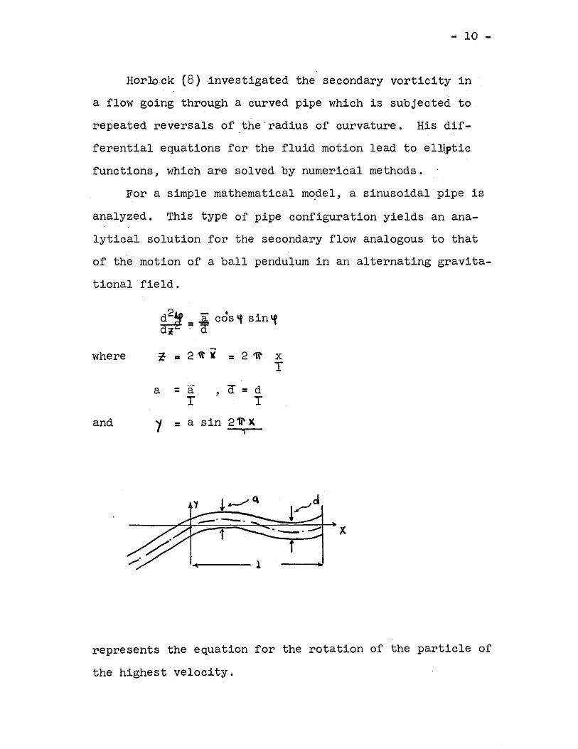
Hor-Io.ck (8) ·investigated the secondary vorticity ina flow going through a curved pipe which is subjected to .repeated reversals of ,the'radius of curvature. His dif-ferential equations for the fluid motion lead to ellwticfunctions, which are solved by numerical methods.
For a simple mathematical m~del, a sinusoidal pipe isanalyzed. This type of pipe configuration yields an ana-lytical solution for the secondary flow analogous to thatof the motion of a ball pendulum in an alternating gravita-tional field.
and
g2~ _ ..ll. cds If sin 'fi ':"'a
~ a 21tlC = 21r X'1
a = a , a= dT T
1 = a sin 211' Xi
where
represents the equation for the rotation of the particle ofthe highest velocity.
- 11 -
Assuming small angles of rotation Horlock found that. .the 'rate of increase of the angle of rotatio~~ increasedwith 'the parameter~for entry conditions corresponding to
d~ = 0 and ~ = 0 at lo = 0 and t:.. = 1\'/4 .
For ~G = ~/2 the solution suggested periodicity ofthe secondary flow for all values of the parameter~ but
dfor ro = 311' the solution suggested the possibility of a
~reversal of direction of secondary rotation, which wouldbecome sharper with increasing values of the parameter.
Experimentally, Horlnck's results checked out prettywell. Instead of·a sinusoidal pi~, a gO-degree pipe bendof circular cross s~ction was cut into segments of 15-degrees each and bolted together. For this set up therate of increase of the angle of rotation was found higherthan predicted.
It was also found that viscosity damps the rotation.as 'f approaches 1ft/2. This was also found to be true bythe author in a par~ially filled with liquid pipe.
In conclusion, Horlock's results seem to indicatethat large velocities may be~produced in bends in whichthe radius of curvature is reversed, and that these sec-ondary velocities must be associated with the large pres-sure losses experienceq in pipes.
II. 2. Experimental WorkThe most complete work on experimental data on
- 12·-
pressure lo~s through bends available to the author hasbeen that published by Beij (9).
Beij investigated the pressur~ loss for several 4 in.ID steel, gO-degree bends of radii varying from 6 to 80inches.
He considered the pressure drop through a bend asbeing made up of three parts: the pressure loss thatwould occur in a straight pipe of the same axial length asthe bends, plus the excess loss in the bend, plus an excessloss in the downstream tangent.
(1)
where Hs = the head loss with characteristic velocitydistribution in a straight pipe of axiallength equal to the distance between thepoints of pressure measurement.
HB = the excess head loss in the bend.HT. = the excess head loss in the downstream
tangent.
making HB = J' V2Hrr=
V2 and Hs = A 1 V2. 9~~, sa~
with the new symbols defined asV = the mean veLoca ty, which is obtained by
dividing the mass rate of flow by the crosssectional area of the pipe.
- 13 -
g = acceleration of gr~vity (standard value).s = the coefficient of resistance for a
straight pipe with characteristic velocitydistribution.
1 = length of the pipe.d = diameter of the pipe ..~...,)= the deflection coefficient .e - the tangent coefficient.
we obtain: (2)
p • ~otal pressure loss.~ • the specific weight of the fluid.H = the total head loss) (measured as the
height of a column of the same fluidas that flowing through the pipe line.)
The last two terms of equation (2) can be combinedto give:
v2H = Hs ~ 7 ~ (3)
where 1 • j + e is the bend loss coefficient.All these coefficients: As) j and {}have been
assumed to be functions of the Reynolds number. The most,,,01'"'1 ..
difficult coefficient to measure proved to be 9 ) the tan-gent loss coefficient. Beij defined a resistance coeffi-cient A. " by the relation:
- 14 -
1 V2a'~
where the left hand term represents the head lossgradient along the downstream portion of the bend.
For a section between the points ~ = a andby integration of the above equation it can be obtained:
A)( (b-a) Va ~
where A~ denotes a mean value of A" for the section inquestion. Experimentally Beij investigated this value forseveral sections downstream of the bend and found no varia-tion of A ~ with Reynolds number. From the experimentaldata obtained". he attempted to derive AK as a function of
that would satisfy the conditions of having a maximumvalue at )( = 0 and steadily decreasing to As" the straightpipe loss coefficient" as ~ goes to infinity. He assumedsuch function to be of the form:
where A 0 and ~ were evaluated from the data.For bends of relative radii less than Rid = 8" the
excess loss in the downstream section of the bend wasfound to be independent of the relative radius" therebysimplifying calculations for such a range .
.With the help of an extensive body of high qualityBeij determined the coefficients A sand? as functionsof the Reynolds number for several values of Rid.
- 15 -
The values of the.straight pipe loss coefficientswere obtained consistently the same in almost all testsperformed. The bend loss coefficients were found inde-pendent of the Reynolds number within the range of alltests performed ..
The bend loss coefficient, when plotted against Rid
resembled qualitatively the shape obtained by Davis.Beij obtained a minimum for 7 in the neighborhood of Rid =.5 and a maximum somewhere in the vicinity of Rid = 15.other investigations have found the following results:Davis and Balch (lO)·obtained their minimum at Rid = 5 to7 "and their maximum at Rid = 15, "for higher values of Rid
the values of the bend loss coefficient begin to decrease.Hofmann's (II) values indicate the beginning of a moregradual rise with cqrresponding lower values of the bendcoefficients. Brightmore's (12) curve starts to rise butsuddenly drops to low values in the neighborhood of Hof-mann's.' For all these different curves, the bend losscoefficient starts to drop in the vicinity of Rid = 20.
Although outside the range of his tests, Beij suggestedthe probability of the existence of a third region in which? decreases, and presumably approaches zero as the radiusof curvature goes to infinity. He concluded, from compar-ing his data to that of the investigators mentioned above,that within the range of Rid • 5 to Rid = 15 or 20, thebend 'loss coefficient is not a function of the flow, the
- 16 -
relative radius or the roughness only. The irregularityof results obtained within this range by differ-ent.observers, and sometimes the same observer in the samefloVl conditions, suggests the possibility of an irregu-larity or instability of the f'Low, This, Beij argues,justifies the drawing of the plot of .1 vs Rid throughthe highest points.
The deflection coefficients, when plotted againstRid, showed a minimum at RID. 3 or 4. Values less than,that yielded sharply rising coefficients as Rid goes tozero and gradually rising .ones for values greater than 3
or 4 ..
The minimum value of the deflection coefficientfound by Beij was zero. In other words, the pressureloss in a bend of about 3 or 4 was found to be the sameas in an equal length of straight pipe. Since the energyloss in the bend must undoubtedly be greater than that ofa straight pipe, it must be concluded that the pressureloss does not give the total energy loss. Hence Beijstates that a complete picture of the bend losses can beobtained only by determining velocity and pressure dis-tributions in successive cross sections of the bends.
Since Beij1s analysis constitutes an outline of mostof the experimental "lark done on pipe bends, no other de-tailed account of any other work will be given here. Plotsof bend loss coefficients against several flow variables
� 17 -
can be found in almost all textbooks on the subject offluid mechanics. Further references on the subject maybe found on the bibliography. Several of the curves men-tioned above are shown in Figure 2.
- 18 -
III. Dynamic Analysis. of Separated Flow Through A Bend
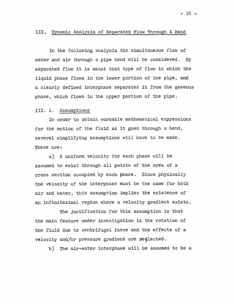
In the following analysis the simultaneous flow ofwater and air through a pipe bend will be considered. Byseparated flow it is meant that type of flow in which theliquid phase flows in the lower portion of the pipe, anda clearly defined interphase separates it from the gaseousphase, which flows in the upper portion of the pipe.
III. 1. AssumptionsIn order to obtain workable mathematical expressions
for the motion of the fluid as it goes through a bend,several simplifying assumptions will have to be made.These are:
a) A uniform velocity for each phase will beassumed to exist through all points of the area of across section"occupied by each phase. Since physicallythe velocity of the interphase must be the same for bothair and water, this assumption implies the existence ofan infinitesimal region where a velocity gradient exists.
The justification for this assumption is thatthe main feature under investigation is the rotation ofthe fluid due to centrifugal force and the effects of avelocity and/or pressure gradient are ne9lected.
b) The air-water interphase will be assumed to be a
- 19 ...
plane surface, and to remain p~a~e during the fluid's pas-~age through the bend.
c) The equations of motion will be applied to a sec-tion of the fluid ofinfinit~simal length along the direc-tion of flow. Friction between this section and the wallsand between this section and adjacent flui~ will be assumednegligible.
All of.these assumptions lead to.a relatively simpleproblem of ~Qlid body rotation under the actions of gravityand centrifugal acceleration. Assumption (b) can bejustified to a certain extent from experimental observation.In the experimental set up described later, visual observa-tion indicated that the departure from the idealized condi-tion stated is not very great, even at angular displace-ments of nearly gO-degrees.
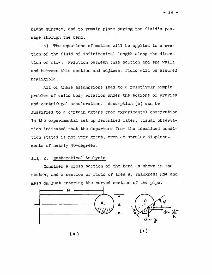
III. 2. Mathematical' AnalysisConsider a cross section of the bend as shown in the
sketch, and a section of fluid of area A, thickness Rd9 andmass dm just entering the curved section of the pipe.
R
dm ~..
--1---- -
... 20 ...
As the fluid enters the bend it is subjected to theact.Lon of a centrifugal force dW\ 'fJ1. ) assumed to act
'"through the center of gravity) which tilts it to the posi-tion shown in (b). Since the center of the pipe is thecenter of rotation) we obtain applying Newtonls law to theliquid phase:
(1)
or) summing moments about 0)
(2)
which simplifies to:
where KQ is the radius of gyration of the cross sectionof the liquid phase with respect ,to the geometric center0) of the total cross section.Defining two constants Cl and C2 as:
C. ::. V~I. an c1 Cz.::· ~
JU~ I<c/~Eq. (3) can be written as:
(4)
- 21 -
Defining two new constants, C3 and related to Cl··,andC2by
C 3 :. \j C,l. +(1.'1.
Eq. (4) becomes:
~:: -C3 l51n(lf-~)]d t.1..
The solution of this differential equation 'is an ellipticintegral of the first kind. TO reduce it to standardform, we make the substitution
~ = \f - ~
which transforms Eq. (5) into
(6)
Multiplying both sides by 2~.~~)gives:
d (il)' ::dt dt
which, when integrated, gives
(8) (M)1. =d t: '
z. C'J (..0 ~ <P + H
- 22 -
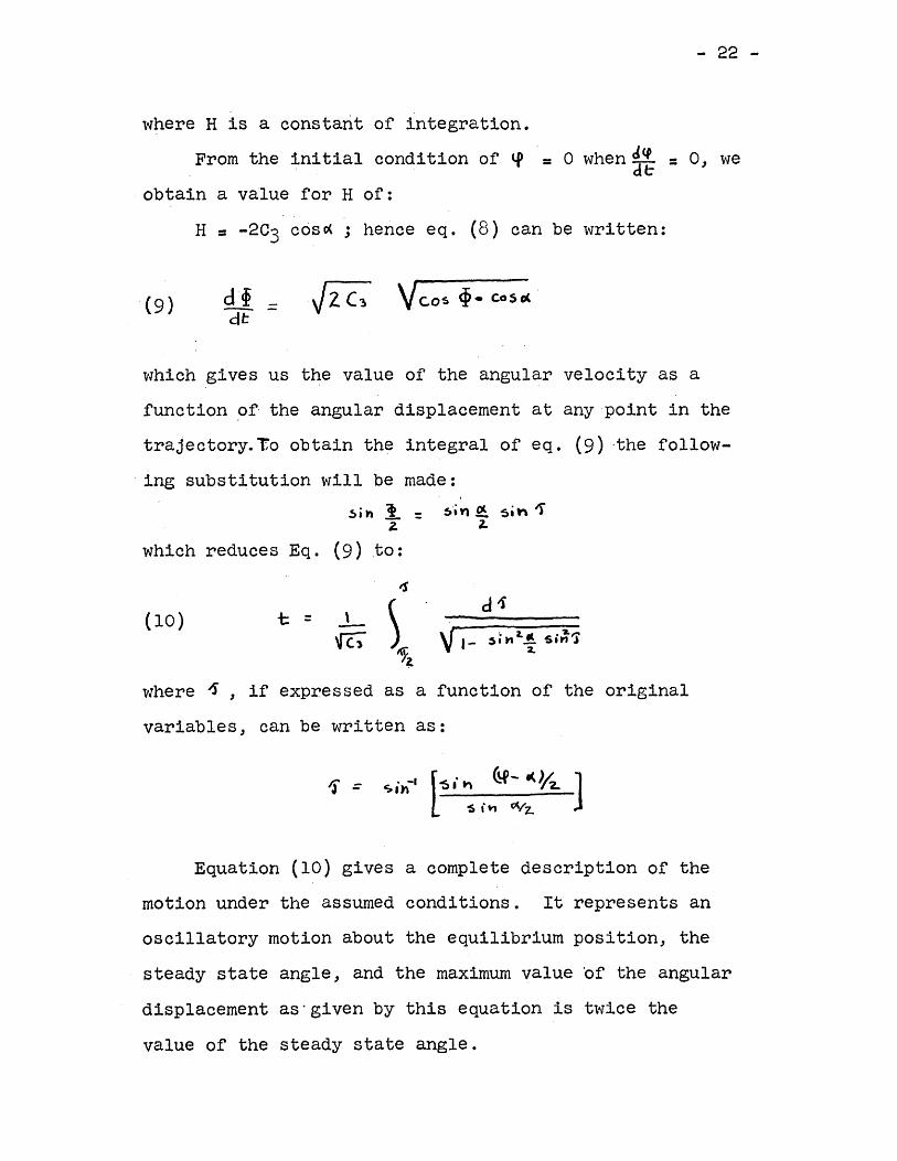
where H is a constarit of integration.From the initial condition of ~
obtain a value for H of:= 0 when dCl = 0, we
de
H = -203 cos~ J hence eq. (8) can be written:
which gives us the value of the angular velocity as afunction ~f· the angular displacement at any point in thetrajectory.Yo obtain the integral of eq. (9) ·the follow-ing substitution will be made:
~; h 1.:: ~"" ~ si'" 1"z. z.which reduces Eq. (9) .to:
IS
(10) t J- )~di
::
~ V 1- ~.",2.~ si~'i~~
where ~ J if expressed as a function of the originalvariables, can be written as:
Equation (10) gives a complete description of themotion under the assumed conditions. It represents anoscillatory motion about the equilibrium position, thesteady state angle, and the maximum value of the angulardisplacement as'given by this equation is twice thevalue of the steady state angle.
- 23 -
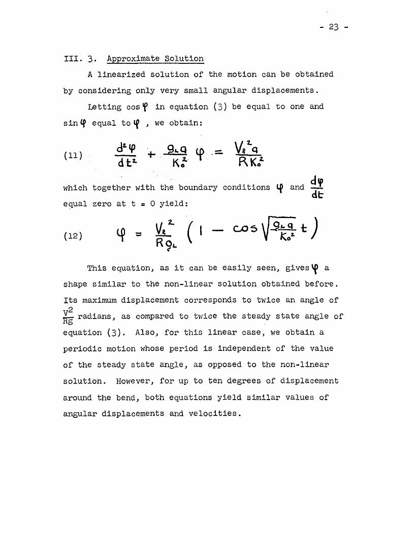
III. 3. Approximate SolutionA linearized solution of the motion can be obta.ined
by considering only very small angular displacements.Letting cos'P in equation (3) be equal to one and
sin £9 equal to If s we obtain:
(11)dz. «p
+ 9&,.Q tp - VIl 2.q.-d tz. K:- RKoZ.
which together with the boundary conditions If and ~de
e qua l zero at t = o yield:
(12) -- ( I
This equation, as it can be easily seen, gives 'P ashape similar to the non-linear solution obtained before.Its maximum displacement corresponds to twice an angle ofV2Rg radians, as compared to twice the steady state angle ofequation (3). Also, for this linear case, we obtain aperiodic motion whose period is independent of the valueof the steady state angle, as opposed to the non-linearsolution. However, for up to ten degrees of displacementaround the bend, both equations yield similar values ofangular displacements and velocities.
- 24 -
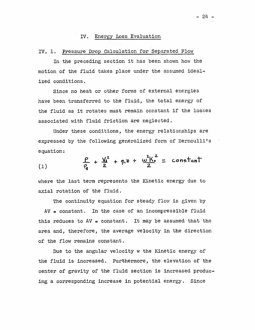
IV. Energy Loss Evaluation
IV. 1. Pressure Drop Calculation for Separated FlowIn the preceding section it has been shown how the
motion of the fluid takes place under the assumed ideal-ized conditions.
Since no heat or other forms of external energieshave been transferred to-the fluid, the total energy ofthe fluid as it rotates must remain constant if the lossesassociated with fluid friction are neglected.
Under these conditions, the energy relationships areexpressed by the following generalized form of Bernoulli'sequation:
(1)
2.K 2-W 0 =z:-.
where the last term represents the Kinetic energy due toaxial rotation of the fluid.
The continuity equation for steady flow is given byAV a constant. In the case of an incompressible fluid
this reduces to AV a constant. It may be assumed that thearea and, therefore, the average velocity in the directionof the flow remains constant .
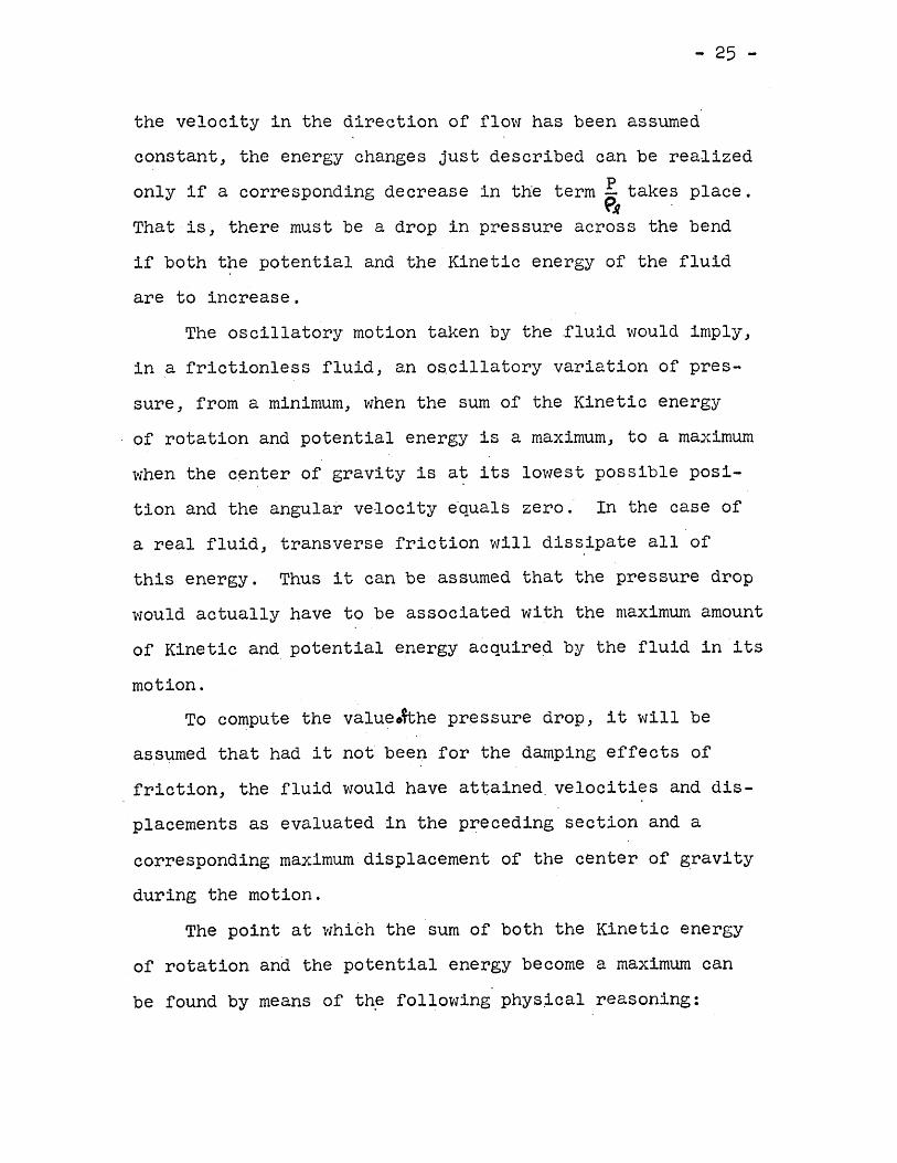
.Due to the angular velocity w the Kinetic energy ofthe fluid is increased. Furthermore, the elevation of thecenter of gravity of the fluid section is increased produc-ing a corresponding increase in potential energy. Since
- 25 -
the velocity in the direction of flow has been assumedconstantJ the energy changes just described can be realizedonly if a corresponding decrease in the term P takes place.
{'.q .That iSJ there must be a drop in pressure across the bendif both the potential and the Kinetic energy of the fluidare to increase.
The oscillatory motion taken by the .fluid would imply J
in a frictionless fluid, an oscillatory variation of pres-sure, from a minimum, when the sum of the Kinetic energyof rotation and potential energy is a maximum, to a maximumwhen the center of gravity is at its lowest possible posi-tion and the angular velocity equa ls zero. In the case ofa real fluid, transverse friction will dissipate all ofthis energy. Thus it can be assumed that the pressure dropwould actually have to be associated with the nlaximum amountof Kinetic and potential energy acquireq by the fluid in itsmotion.
To compute the valueo~he pressure drop, it will beassumed that had it not been for the damping effects offrictionJ the fluid would have attained. velocities and dis-placements as evaluated in the preceding section and acorresponding maximum displacement of the center of gravityduring the motion.
The point at which the sum of both the Kinetic energyof rotation and the potential energy become a maximum canbe found by means of the following phys~cal reasoning:
- 26 -
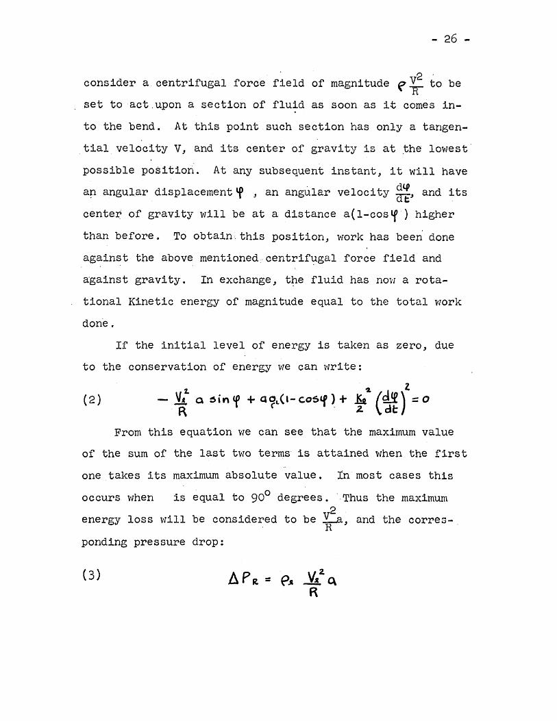
2 'consider a centrifugal force field of magnitude fir to beset to act ,upon a section of fluid as soon as it comes in-to the bend. At this point such section has only a tangen-tial velocity V, and its center of gravity is at ~he lowestpossible position. At any sUbsequent instant, it will havean angular displacement'P s an angular velocity g~J and itscenter of gravity will be at a distance a(l-cos~) higherthan before. To obtain, this position, work has been doneagainst the above ment toned. cent.r-Lf'ugal force field anda-gainst gravity. In exchange J t~e fluid has now a rota-tional Kinetic energy of magnitude equal to the total workdone .
If the initial level of energy is taken as zero, dueto the conservation of energy we can write:
~ ~ Z- ~ a :sin (I) + QOL(l- c.oSlf ) + ~ (~) ::0R 1 ( '2. de
(2)
From this equation we can see that the maximum valueof the sum of the last two terms is attained when the firstone takes its maximum absolute value. Inmost cases thisoccurs when is equal to gOO degrees. ',Thus the maximum
2energy loss will be considered to be ~ BJ and the corres-,ponding pressure drop:
- 27 -.
where ~PR denotes the drop in pressure through the benddue to rotation.
Although at the present moment this rormu~a does notseem to have too much practical use due to the difficultiesencountered in evaluating a, it will be shown later on howsome of -these obstacles can be overcome and "a" convenientlyapproximated from a knowledge of the flow variables.
IV. 2. Extension to Annular FlowSince the previous analysis has been made under the
assumption of separated flow, it is expected that formula(3) would only apply in such cases. However, with a slightassumption, this restriction can be lifted to comprise alsoannular t'Low, This wourd indicate a mucn.wf.der- range ofuse, since a great percentage of two phase flow cases foundin practice are e·ither annu lar-or separated.
To extend the analysis to the case of annular flow itwill be imagined that as annular flow enters the bend theportion of fluid next to the interior wall will try to moveoutward as a consequence of the centrifugal force actingupon it.
For this motion to take place without producing dis-continuities in the flow, it will be assumed that-suchmotion will be realized in the form of a rotation over thewalls until a fi~al position, as shown in the graph, isachieved. Again, under the assumption of no friction, this
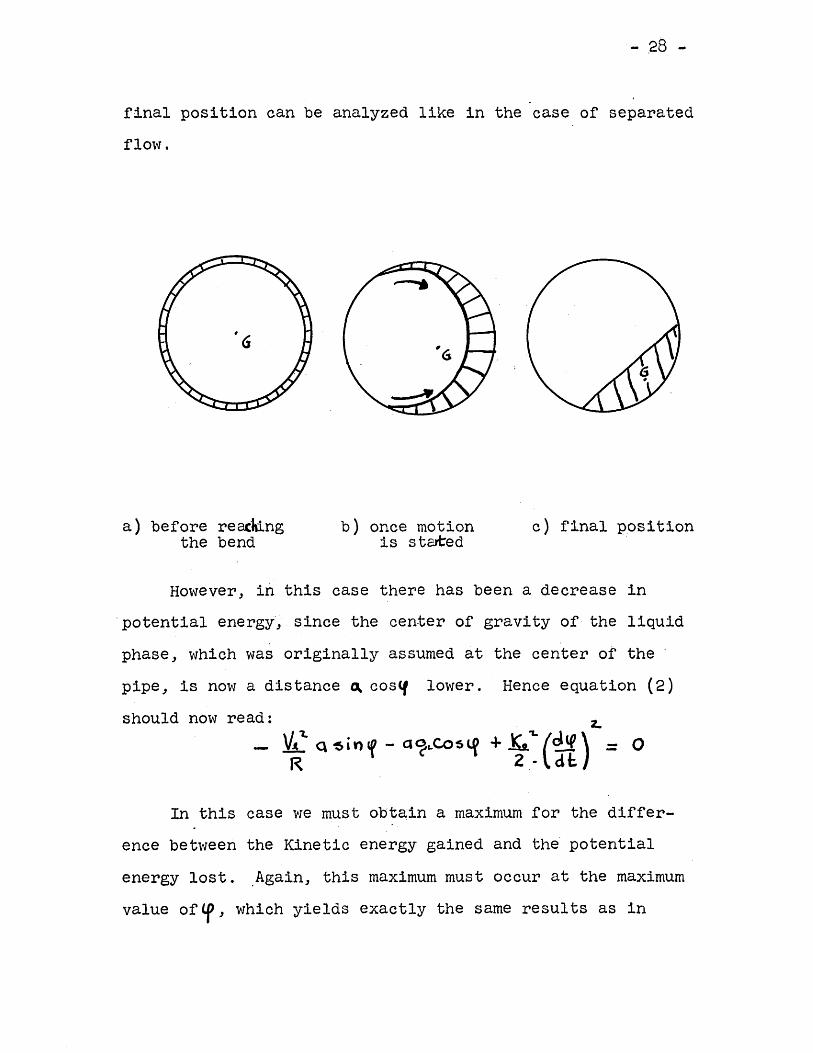
- ,28 -
final position can be analyzed like in the case of separatedflow.
a) before re~Mngthe bend
b) once motionis stated
c) final position
However, in this case there has been a decrease in'potential energy', since the center of gravity of the liquidphase, which was originally assumed at the center of thepipe, is now a distance ~ cos~ lower. Hence equation (2)should now read:
In this case we must obtain a maximum for the differ-ence between the Kinetic energy gained and the'potentialenergy lost. Again, this maximum must occur at the maximumvalue of'f' which yields exactly the same resul ts as in
- 29 -
separated flo\"/.
IV. 3. A Method to Determine the Gas-Liquid Velocity RatioOne of the basic char-actier-Ls t.Lcs of two-phase f10w is
the fact bhab., in general) the liquid and the gas f~ow a~"
different velocities. The ratio of these velocities is avery difficult quantity to measure in practice. Althougnvarious attempts have been made to simplify its determina-tion~success has been much less than desired. 'On the otherhand, this flow variable bears such importance that even arough approximation of its value would clarify many a prob-lem. In our case) the value of this ratio will enable usto compute the ratio of the area of the gaseous phase atany cross section of the pipe) to the area of the liqUidphase.
This variable, in turn, will link the geometry of theflow to the continuity requirements, and therefore relatea pressure drop for any given quality, where by quality itis meant the weight of gas floWing through the pipe in rela-tion to the weight of the total gas-liquid mixture.
Before making any attempt to determine Vg/v, let usdefine some of the variables involved.
If the "static quaLf.by " of the f10\'1is defined as theI 'fraction by weight of gas present within the pipe at any
given instant, we can write:
(6)At
X~ - "'"t-IU. + ~v, 1rg
- 30 -
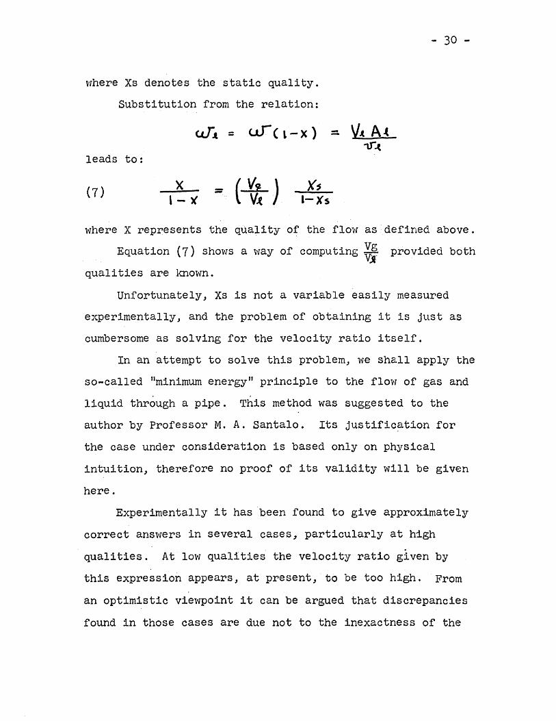
where Xs denotes the static quality.Substitution from the relation:
WA. = We L-X) - VA. At.,r.(
leads to:
(7) x - (~) )(sl-Xs1- ~
where X represents the quality of the flow as defined above.Equation (7) shows a way of computing ~i provided both
qualities are known.Unfortunately, Xs is not a variable easily measured
experimentally, and the problem of obtaining it is just ascumbersome as solving for the velocity ratio itself.
In an attempt to solve this problem, we shall apply theso-called "minimum energy" principle to the flow of gas andliquid through a pipe. This method was suggested to theauthor by Professor M. A. Santalo. Its justific~tion forthe case under consideration is based only on physicalintuition, therefore no proof of its validity will be givenhere.
Experimentally it has been found to give approximatelycorrect answers in several cases~ particularly at highqualities. At low qualities the velocity ratio given bythis expression appears, at present, to be too high. Froman optimistic viewpoint it can be argued that discrepanciesfound in those cases are due not to the inexactness of the
- 31 -
assumption, but to the simplifications that'must be made, tosimplify the mathematical operations concerned with their.application.
In the case of two phase floVl it is reasonable toexp~ct that the velocities and areas of the total crosssection occupied by the fluids will adjust themselves insuch a way as to result in minimum energy loss and hence aminimum energy to drive the fluids through the pipe will benecessary.
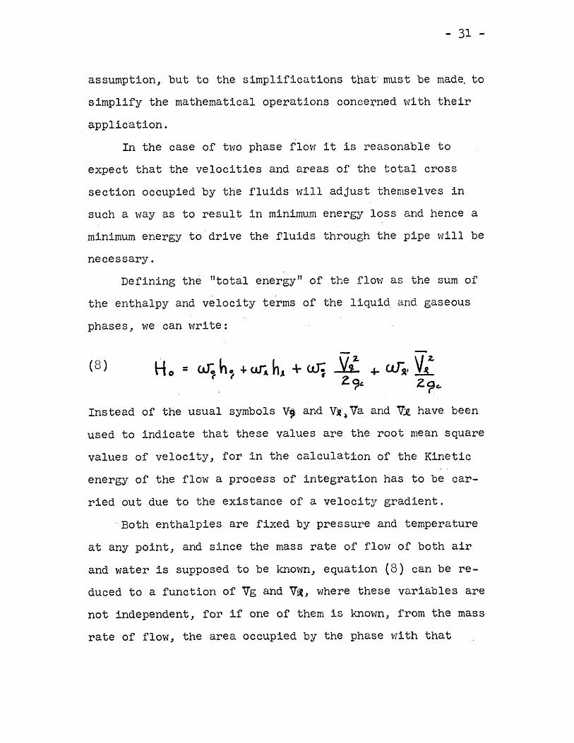
Defining the "tot.atenergy" of the flo\'las the sum ofthe enthalpy and velocity terms of the liqui~ and gaseousphases, we can write:
(8 )
Instead of the usual symbols ~. and V~·~Va and Vll. have beenused to indicate that these values are the root mean squarevalues of velocity, for in the calculation of the Kineticenergy of the flow a process of integration has to be car-ried out due to the existance of a velocity gradient.
'Both enthalpies are fixed by pressure and temperatureat any point, and since the mass rate of flow of both airand water is supposed to be known, equation (8) can be re-duced to a function of Vg and V~, where these variables arenot independent, for if one of them is known, from the massrate of flow, the area occupied by the phase with that
- ~2 ..
velocity can be calculated. This enables us to determinethe other fluid's area and hence its velocity.
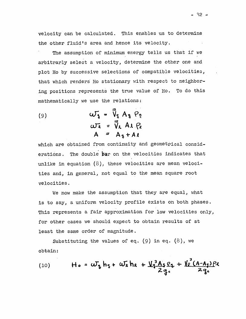
The assumption of minimum energy tells us that if wearbitrarly select a velocity, determine the other one andplot Ho by successive selections of compatible velocities,that which renders Ho stationary with respect to neighbor-ing positions represents the true value of Ho. To do thismathematically we use the relations:
(9):::
= ' V~ A~ P~:: VA. Al.~
A~ + A.t--which are obtained from continuity and geometrical consid-erations. The double ))ar on the,velocities indicates thatunlike in equation (8)J these velocities are mean veloci-ties and; in general, not eq~al to the mean square rootvelocities.
We now make the assumption that they are equal, whatis to say, a uniform velocity profile exists on both phases.This represents a fair approximation for low velocities only,for other cases we should expect ~o obtain results of atleast the same order of magnitude.
Substituting the values of eq. (9) in eq. (8), weobtain:
- 33 -
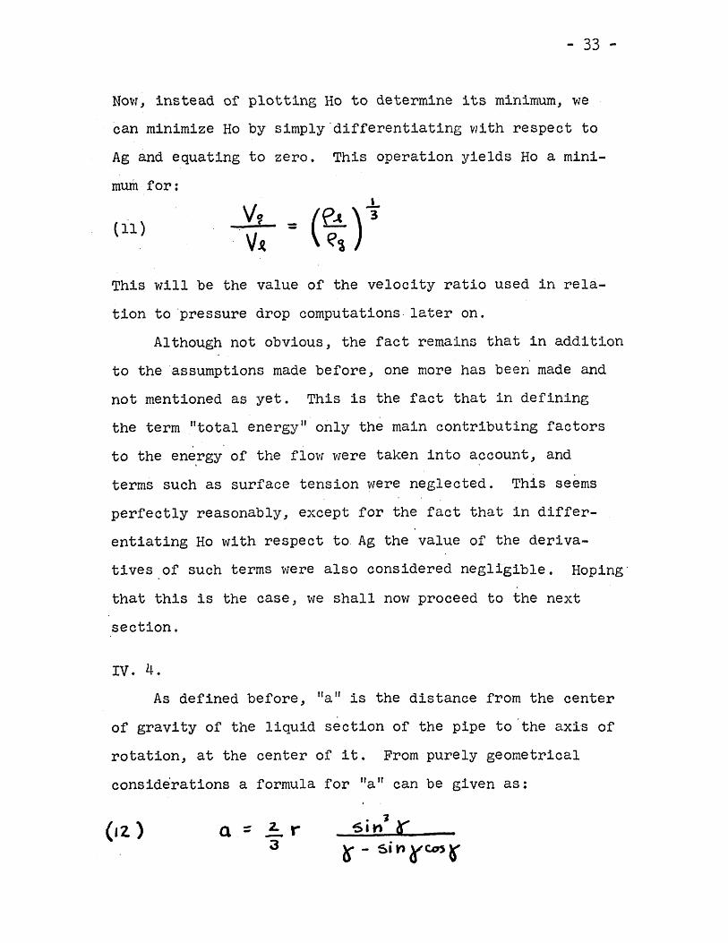
Now, instead of plotting Ho to determine its minimum, wecan minimize Ho by simply 'differentiating with respect toAg and equating to zero. This operation yields Ho a mini-mum for:
(11)
This will be the value of the velocity ratio used in rela-tion to 'pressure drop computations later on.
Although not obvious, the fact remains that in additionto the "assumptions made before, one more has been made andnot mentioned as yet. This is the fact that in definingthe term "total energy" only the main contributing factorsto the en~rgy of the flow were taken into account, and
, .terms such as surface tension were neglected. This seemsperfectly reasonably, except for the fact that in differ-entiating Ho with respect to Ag the value of the deriva-tives.of such terms were also considered negligible. Hoping'that this is the case, we shall now proceed to the nextsection.
IV. 4.
As defined before, "alf is the distance from the centerof gravity of the liquid section of the pipe to 'the axis ofrotation, at the center of it. From purely geometricalconsiderations a formula for "an can be given as:
(&2. ) a :: ~ r3
- 34 -
where r is the radius of the pipe and~ is half the anglesubtended by the chord formed by the liquid interphase.
Also, Rg, or the ratio of the area occupied by the gasto the total area of the cross section can be written as:
(13)
or
(14)
Combining formulas (12) and (14) a tables can be built togive values of Ita"as a function of Rg. In turn, Rg can becorrelated with other variables in the following manner:
From the definition of quality:
-- <?" Vi A) ,e1- V,.Al -'-~A. ~J. At
which can also be written as:
(15) X ::I .
Taking the value of ~; calculated in the preceding sectionwe can obtain values of Rg and hence of "alt as function of the
\quali ty of the flo\'l.
Using equation (3) a pressure drop computation' has beenmade for velocities of 5, 10 and 15 ft/sec and bends of re-lative bend radii of 6, 4 and 1. The results have been
- 35 -
plotted against quality and Rid. (See figures L~ to7 ).The parameter used to correlate the pressure drop has
been the pressure drop that would occur in flow of onlyliquid through the bend, \-litha mass rate of flow equal tothat of the two-phase flow case.
Curves for these values were found experimentally asdescribed in the next section.
- ~6 -
v. Experimental Work
In order to carry out experimental investigation on-the pressure drop of two-phase flow in bends, Cohen (13)has constructed the apparatus shown diagramatica11y infigure l~.
v. 1. ApparatusThe apparatus consists of four sections: mixing,
entry, test and exit.In the mixing section the water and air are brought
tqgether from their sources, their mass rates of flowmeasured by nozzles installed in the individual pipes) andare finally mixed and introduced into the entry pipe. Mix-ing was accomplished in a jet--type steam ejector in which ajet of air was introduced i~to the center of an annularflow of water. This type of mixer was used because itfacilitates obtaining a'fairly steady separated flow) re-latively free from disturbances.
The entry section consists of 4 1/2 feet of 1/16 "thick, 3/4 If ID clear lucite pipe attached at the mixer atone end and to the text section at the other by plexiglass
,flanges bonded to the pipe. The purpose of this pipe wasto permit the flow to fully develop before entering thetest section.
Pressure taps of 0.040" diameter were placed every 12"along the length of the straight pipe.
- 37 -
The test section .consisted of a removable 98bend.Bends of relative radii of 6,4 and 1 were used to insurea wide spread of investigation.
Three feet of straight pipe fitted with two morepressure taps comprised the test section. It is at thisregion that disturbances of the flow may be damped out be-fore a final reading of the pressure is taken At the
Ioutlet of the pipe a gate valve was installed for the pur-pose of controlling the pressure in the entire apparatus.Extreme care was taken to keep the entire set up on ahorizontal plane.
v. 2. Performance for vlater OnlyThe total pressure drop through the bend was assumed
to be the sum of the frictional loss that would occur in astraight pipe of the same axial length as the bend and theloss due to factors other than axial friction. These losseshave been called by Cohen secondary losses and in thispaper are denoted by the symbol (AP)w .
The total bend loss (AP)e was found by plotting thepressure drop from tap 1 to each of the other taps against
AP/distance along the straight pipe. Aline representing /~L
~Tas drawn through points three and four and extrapolated tothe beginning of the bend. Similarly, a line with the sameslope was put through the point representing b. p~" andextrapolated back to the bend. The vertical distance between
- 38 -
these points represents total bend pressure loss. The sec-ondary loss was found by sUbtracting A~~l times the axiallength of the bend, from the total pressure loss.
v. 3. Performance for Two-Phase FlowAn attempt was made to verify Martinelli's (14) cor-
relation'with this set up. Investigations were carried outfor'qualities up to 0.1 with air pressures varying fromforty to fifty psig and water pressure varying from fiftyto sixty psig.
All of the data taken corresponds to either annular orseparated flow, and it was correlated in the manner shownin figure 8.. The curve for the bend of relative radius ofG was not shown because the accuracy of the apparatus didnot permit a careful measurement of the pressure drop forthis case. The values used by the author for (AP)~ infigure 4 were actually computed by assuming that the ratioof the total bend losses to secondary losses within thisrange was equal to 1-5. This result was experimentallyfound by Cohen.
- 39 -
VI. Discussion of Results
To verify the validity of the equations obtainedusing the simplifying assumptions listed, observation ofthe angular rotation of the fluid was made.
The assumption of a plane interphase appeared valid-at low velocities. Even at angular displacements closeto 90 degrees it could be visually observed that the inter-phase was nearly plane.
Comparison of the predicted values of angular dis-placements with those found experimentally showed a largeamount of damping after approximately 30 degrees of fluid~isplacement along the bend. The amount of damping seemedto vary according to some power of the angular velocityand of the steady state, that is to say: nonlinearly.
The amount the maximum angular displacement exceededthe steady state angle seemed to decrease as the steadystate angle approached 90 degrees. In no case did themaximum angular displacement exceed 90 degrees.
Even though there isn't enoug~ data to make a generalstatement in this respect, it can be supposed that the sys-tem had a damping below critical, and that oritical damping1s the limiting case as the steady state angle approaches90 degrees. (See figure -3)
The predicted curves of pressure drop are independentof velocity, extending in this way to bends Martinelli's
- 40 -
results for a straight pipe.A comparison of the predicted pressure drop curves
with those found experimentally shows a close agreementas to their shape.
Quantitatively,. the predicted values fall a greatdeal below those found experimentally, except in the caseof assumption of a gas-liquid velocity ratio of unity,when the calculated -values of pressure drop lie above theexperimental. This suggests one of two things: (a) eitherthe calculated qualities are not in close agreement withthe actual qualities, or (b) other phenomena taking placein the bend, besides rotation, give rise to a large amountof pressure drop.
The relation between the geometry and continuity ofthe flow was obtained by deriving, under simplifyingassumptions, the equation ~: (~~)~. Hence the cal-
VA. e"culated qualities are as close to the actual qualities asthe above relation is to the actual velocity ratio. Itis the belief of the author, though, that besides rotationin the bend, relative motion of the fluid particles havegreat influence on the energy loss, because of resultingturbulence and change in velocity profile. But whateverfactors, besides rotation, may influence the loss of energyin the bend, the similarity of the predicted and experlmenta]curves seem to indicate certain proportionality betweenthese factors and rotation of the fluid in the bend.
- 41 -
A plot of pressure drop against relative radius indi-cated a minimum loss for an Rid of 4, for all qualitiesunder investigation. This startling fact has not beenanalytically proven by the author due to the extreme dif-ficulty, if not impossibility, of obtaining a formula forpressure drop a function of Rid alone. Nevertheless, thepredicted results have been corroborated in the experimentalwork of Cohen.
The plot (shown in figure 7), shows, a decrease in thepressure drop ratio APg ....APcu as Rid approaches 4,
APeuthen it increases agai~, presumably in a st.eady manner toan Rid of 6. From there, on it is impossible to determinewhat ''1illhappen because bends of relative radii largerthan 6 were not investigated. The assumption can be madethough, that the pressure drop.ratio continues to rise fora while longer until reaching a maximum, and then it de-creases as Rid goes to infinity.
This result can be referred back to Davis's result,(figure 1) where the bend loss coefficient 1s seen to de-crease from an initial maximum at Rid =·1 toa minimum ofRid = 4. Although he only considers a single phase, therecurrence of the same phenomenon in the case of two-phaseflow is significant.
As a final conclusion, it can be said that the accurateprediction of the relative positions of the pressure drop
- 42 -
curves for Rid of 1, 4 and 6, from rotational losses alone,indicates a definite influence of the latter in the totalpressure drop of separated and annular two-phase flowthrough a bend.
- 43 -
APPENDIX"Pressure Drop 'When Gas and Liquid Flow at
the Same Velocityll
The gas-liquid,velocity ratio calculated in SectionIV shows close agreement when compared to experimentalvalues, at high qualities. As the quality decreases, thediscrepancy between the calculated and actual value be-comes larger and at very low qualities only the order of"magnitude is preserved.
Since all the pressure drop investigations were car-ried out at relatively low qualities, it is expected thatthe actual velocity ratio was smaller than predicted.Thus, the predicted curves fall more than what theyactually should below the experimental. An idea as towhat would have happened, should the velocity ratio hadbeen smaller, can be obtained by considering the limitingcase of equal velocity of both phases.
Figuresl0~ncl11 show the predicted pressure drop curvesfor bends of Rid of 4 and 1. As it can be seen, the newvalues fall much closer to the experimental values for verylow qualities. As the quality increases the predictedvalues become larger than the experimental.
The only conclusion that we can derive from this re-sult is that even though there is no reason to believe that
- 44 -
the actual gas-liquid velocit~ ratio is closer to unitythan to the previously calculated. value, one can assume
valuethat if its actual had been used to compute the pressuredroPJ the ·curves would have la~a somewhat closer to thee~perimental values.
- 45 -
BIBLIOGRAPHY
1 . Dean, \'1. R., "The streamline motion of a fluid in acurved pipe". Phi Meg. (7), 4, 208 (1927) and5, 673 (1928).
2. f'l. Adler, "Stromung in gekrummten Pohren". ZA~IM, 14 J
257 (1934).
Prandt1, Fuhrer durch die stromungs1ehre, 3rd. ed.,Braunscheweig, 1949, p. 159. Also Eng. trans1.by MIss W. M. Deans, London 1952, p. 168.
4. Squire, H. B. and \'linter,K. G. "The secondary flowin a cascade of curfoi1s in a non-uniform stream"Journal of Aeronautical Science, Vol Ie, No. Lt, .pp. 271-2'('(, 1951.
5. Hawthorne, vi. R. "Secondary circulation in fluid flow"Procedingsof the Royal Society, London, Series A,Vol. 206, PP. 374-3b7, 1951.
6. Davis, G. J. 1910, Bull. Univ. Wis, Engng. Series,6 No.4.
7. Eichemberger, H.P. 1951, 1\1. Se. Thesis, M.I.T., alsoJ. Matts. Phys. 32, 34.
8. Hor1ock, J. H. "Some ex~eriments on the secondaryflow in pipe bends. I Proceedings of the RoyalSociety, London. Series A, Vol. 244, pp. 33J-346, 1956.
9. Beij, K. H. "Pressure losses for fluid flow in 900pipe bends." Journal of Research of the NationalBureau of Standards, Vol. 21, 1938.
- 46 -
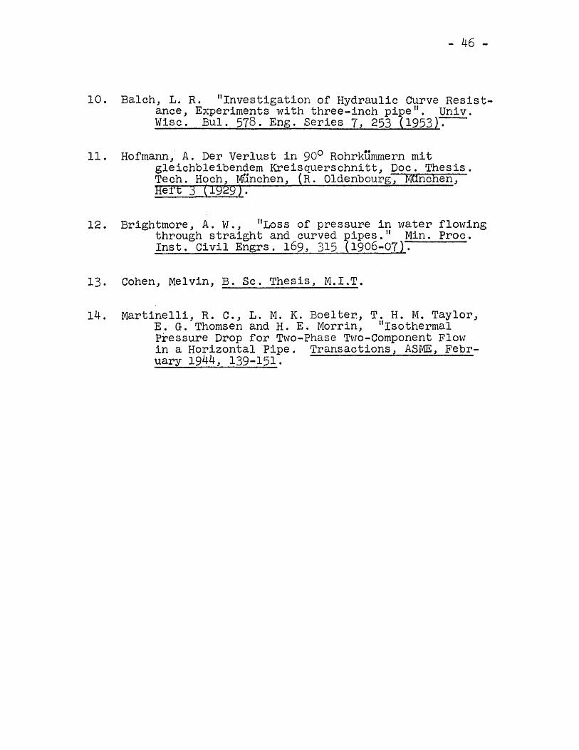
10. Balch, L. R. "Investigation of Hydraulic Curve Resist-ance, Experiments with three-inch pi e". Univ.Wisc. Bul. 578. Eng. Series 7, 253
11. Hof'mann, A. Der Ver1ust in 900 Rohrkummern mitgleichbleibendem Kreisquerschnitt" Doc. Thesis.Tech. Hoch, MUncheD" (R. Oldenbourg" MUnchen,Heft 3 (1929).
12. Brightmore J A. vi., "Loss of pressure in water flowingthrough straight and curved pipes. II Min. Proc.Inst. Civil Engrs. 169, 315 (1906-07).
13. Cohen, Melvin, B. Sc. Thesis, M.I.T.
14. Martinelli" R. C." L. M. K. Boelter, T. H. M. Taylor,E. G. Thomsen and H. E. Morrin, IIIsothermalPressure Drop for Two-Phase TVlo-Component Flowin a Horizontal ·Pipe. Transactions, ASME, Febr-uary 1944, 139-151.
i.o
0.9
) 0.&
0."("
0.'
0.5
0.4
03
0.2
0.1
- 47-
o 2 ~ , &
~f\/d
F io 1. - E++~c.t of t'e\Qt\~e radius ont'
bend \055 coe.f4'icients.(A.fter }~~is)
0..-------------- _o.'t
..,
a> Balch(i) Dt\vi~@) 6riShtwa &re
@ H 0"" vn an.,
o ..... ----r..-.....& .......~r_~~~~ ......~~- ..... -~---'o· 11
R/J). Z • Bend coeffi,ient~ found band
0-\ \, e r in v e~ t I 0 Q 0 r s , ·,
160
EiC)3.- Calculated on~peYimentalv a \ lJ e 5 of'"" lUi don ~u Iart" 0tqt ion
of 0 r a glp.L.b a It-f;ll e d wit h \ J' ~ Ui.d,o~ o.'tSO i.., 1.D. OY1d O.3'tS it. rQ1fU~of c urv c t u re.
90
\0 it /~ec.150
120
60
30
3-0. 3<1-..~Q.~<1
,-- "-Q.. 10ca- 8
-50-
100
50 .V
Vf-----
//
/""- -
I'
I4
z
o 0.04 0.01 0.1Z. 0.16 0.10
Q U Q Iity
Fi9 '1-.- Pte,uur. Dtoe Correlation for Q Qe",J of %. 6
- 51-
lOO
so -:~
V
///
VJ
10
6
6
2.
1o 0.01 0.01 O.IZ 0.16 0.20
Qua' " ty.fi9 5.- Pre 55U I-e Dtap Cayre Iati 0'" tot a Ben d of ~ :<:1
1,.....,0-<l 3- -... 0-ex <i
r- "'-"0-<i""- I 0
-52-
ISO
V
/V
7'I
J
/
100
50
6
6
4
1o 0.04 0.'6 0.200.0& O.IZ
Qual'If)'
Fi 9 6,- Pte~~ure Dt'op Correlation tor Q Behd 01~ =-1
3-Q. 2.0<J l- ""4- 0-u: <l,-. ......,
0-<I-
,.5 0
)(: '.ITO
100
so
.10
J o 1 Z 3R/cl 4 5 6
F i 0." 7 . J t1 f' I0 e n c.e ot t', e \ at·, ve r ad i VoS 0 \1
P\'"l?~~ul'e chef 'htolJ~~ a bend.
-53-
-54-
:.'.;:::;:::::::::::::::::::::::::::~:;!:'
:..
!,
....i
:::.:<::~:.:::.-7.~~
::.::.:::::.::
::::::::
:::::~::
•..•.
.;---
.+..1'-:"----t·.
.;::::::::::::::::::::::::::::::::::::....
;~~
::1.:
.t·..·::l:~~~~::::.;::::.::::::.:::::::::::::::::::::::::::
;I;~t.
l'':1:
.::
.:::::::
::::::::::::.::::::::::::
::::1-.;'~
.'~
1'·'·
:"':.'
.::':"
.
..t:-:':-i~~-:~-.~-+~_-~~.-t-~~~~~~:~~~:~-~~~~~~~~~:~~~~~~~~J,.;.~~~~
~";'~~---':"+-~~:t~•..iiI~IL~-+---:---':-~'.-
:l-~~~._-.~"j"':':.:yt-:-..-:+
---+-..-.
'.........:::::1
I'"1
.:'.:::::~:t::::::::::::::::::::::~
~.
L•
:.'..L
:.I.·~:
...-.t-.
:-::+.-:-::-+-:.:....:::-::.+:;-:::+:-:::+:-.:~:~:.~::~:
:~:~:~~-.;,i...:..~h:,~::iI-.-;I,~~-~:-1
"i....:~.~-roo~~f'-':-+-,-.-:
t-:~-=--,:+.--+--
_.:~:_::~._::_::+:~~_:::+;
:_::.+':_::+::~::~:~::_:-+:~::_:~:~~~'~~~~~I
~~~.~;~.~_.
;.:
::.;''.1':::
~:...
./:::::~r:,::':::::'::::::::::...~:~!
..~.tll..-_:I::l·
·r'L::~:;·.::::':~~~
:~t~~~~~~~~::~~~~
~:~~:::~!'I:Ji
~~
i:I
I~.~:i-::::::::
..:::.
~:.....
-
.....-=-..:-
l::~:~:~~:~:r~~~~::;~:~~:~~~:::~~~:
;~0
~.IIi
.I~~~)::.·.:;:::::.j.:
~:::-l-.4~::-::t-:-.::+.....
:::.-:::+::-:::+-::~::f-.:-'::f-::-::+:-::-:+----f--;~~~
....+--!.....;::r...:~.--.
.--:....
-:-,,~
".:1......
-+---+
-t~.+-----+
-·
~~
•.~.i
...
-·..
~.......'--
":::.:::.:.i:.::::::::::::::
::::::::
:..+
:~:
~::..:~':'':::~:.
~:::::
::::1::':::::
::::::::
::::::::
~..
I.Tt~'I..··
.1_"
---.....
:::.;':::::::::
..::::
::::::::
::::::
~:
:"
j~!
.:....:
'j:::::===.
-:.-:+-.\\~-:r-~-::-1~-·::....J-~~~+-i~-~~~~;-~~~~-~:+:-~:-;~+-:-:-:~-+--+JIJ~~""l------·
-.:.r..·t~·~---~"l"-~_..-to,:-~~~~~.
-....:.~
.:::::i::::::::
.:::::::
:.::::::
;~
I:.,
'1'"
•.•
.•
:..~
::;,"j::::
::::::::
::::::::
::::-..-.~
••
j..!
.L
:::::::::.~
....-....-~--.
.~
~.'..
,"
,.
...::\:·:.L:.;;~::;:::::;:~::~:~
~~!
i'!-::::::::
~.~~-~:;~.
\, ....·\::r I::::::::::::::.:::.:
...II!
i::''.:~:~~~:~~.:~~-~~.~.
......
•..
•..
.•.
...•
....-
.----
f-orI..j.._.......-.~fl-'
"...,.
"',--...:N:::..·.<rl :.:::.<:'.:
:.~~:';".
Ii.\•.:....
:::::~
:::.:
."';
...:.:':.:::.:~.:...;,,;:
~
ul-r\r-l·:)tW..:._.---dl---j_·rfJ;:
:~:;~~~~:~I
II'
j"::.!:..
:::,~.
'fIf!
..:::~::
::;!:
-~·i-.i"i.'
~\·"f----·!-Tr1---..:.
:!
~.~:..
iI
::
;N
··l.:~·'h
8l:-r-:::
·;;:
..!.:
I;
I.
..i
:-··T
··-~-f----.-..-
---"-..I.
--:-1---'-
00
--.
-,-f-t-.'..-
-~,--'--'r
-t---4--
I,.:
'::
I:.".,
':I
•I
...,"
:..
.....!'oe.......
••.1
...l....!-._.t-.~.-...L_~_l_~._l~_._~~-.~.
.i.._j..1;~-__-.tIoooou:~;...~.....'-.~i-...+.-..-_;-._-_.I-_--+-ij~-t--
•I'
I.,
":"""'0.'.
~I
:.
I::.::
:':
~~;~i
,I
I::
:::
'---::..~
I-
.........~
:~
l·
I"•.
,,
•I,
':~""""";
•;
..-t...
-~.:...
_.~•••_
•.•~_.
-_.~_.~...
-•.:---
-;
.~..I·t
._~._.~._.:~i
~1:
.~:
.ii
~,i'
:~
1
I
....----J-.
-55-
, ~o; I ••lJ ~ . . .
t8!···· .
!7" ..
.. .• • t, •• ~~._._ " _ ••••••••••••••••••• -•••••. .
: -. :.................•
-56-
25'"0 r----r-----.------,.-----,.------.
ZOO t------t-------J------~----~------J
'00
3r»;D..<J 3......., ~+ a-ct <],..... -n.(j~ 50
2. 0 t-------f---i~----+J------~----~--...:---I
1.O"-_--L __ I-.""I; 01-- -4------..I.L..---~
Fi 0.10 .-
O. 02. 0..01 0 .06 0.0 8 Q '09".·"t1
C oMp4'i5oJ) of rr.di c. ,="~d aft" ttAffri"""i:al
a
2,00 '-"---~I---------li-------lf--------it-------t
100
3~Q. 3<l ~......, CL+ <3~ ""'-J~0-<J 50......,
20 ~---4"'---lI-+------lI------t-----,tJ"---t--------1
1.0 L-----L_I-----I'----------------...lJ-- __ I-- -.-..II....- •
O.OZ, O.O~ 0.06 0.08 0.10
G.uali +rC Omp'Q"'i~Ot1 of ~t"edi c:te.d and experimentalvQ\lJe~ of pre.ssu,.e drop to .. a j,endo~ ~1(I:1
o
Fio.11 --(
/
1lito
"
NO
I.Ljj.rLf.7.L
-58-