Embed Size (px)
Citation preview
8/11/2019 StVAR GuideHarmonics Bro Prod
http://slidepdf.com/reader/full/stvar-guideharmonics-bro-prod 1/6
Guide to Harmonics POWER QUALITY
Reactive Power and Harmonic Compensation
The Basics of HarmonicsAll business types, commercial, industrial, governmentand energy/utility have a concern with power quality. The reliable and continuous delivery of “expected quality”electricity is critical for proper daily operations. From a
manufacturing facility to a brokerage rm, the need forutility grade or better power exists. Further, with moredigital technologies installed on the load, “high nines” typepower requirements keep increasing. Environments richin harmonic content can place serious burdens on powerdistribution systems and the equipment to which it isconnected.
AC electrical loads generally have resistive, inductive andcapacitive components. To take a step further, there arethree major classes of harmonic producing devices .
1. Ferromagnetic (magnetizing) device—basically a coil
wound around an iron core. Examples here includetransformers and motors. These devices normally donot present a problem unless resonant conditionsexist.
2. Electronic rectiers and inverters. Examples ofthis include computers, adjustable speed drives, andUPS systems.
3. Arcing devices. This can include uorescent and vaporlighting, arc welders and arc furnaces.
Simply put, harmonics are currents and voltages that have
multiplied within an electrical system. Commonplacelinear loads continue to become more non-linear due toelectronic and digital type devices. Because of this, thetraditional sine wave shape has changed, reecting thesemany current and voltage distortions. Harmonics are
created mainly from silicon-controlled rectiers (SCR’s),and solid state diode converters that are found in a widerange of equipment types. The operating design of SCR’sand converters changes AC to DC or DC to AC, in a highspeed, rapid pulsing manner, emitting a spectrum ofharmonics, which is “captured” in the power system.
A sine waveform has a fundamental frequency of 50Hzor 60Hz (400Hz for some other applications), whichis measured in integer multiples of the fundamentalfrequency and listed as “orders.” Common rating examplesin a 60Hz (fundamental) system would include a thirdorder harmonic (3 x 60Hz) 180Hz; fth order harmonic(5 x 60Hz) 300Hz and so forth. A harmonic spectrumconsists of the fundamental frequency (60Hz), with a valueof 100%, along with a current harmonic distribution andtotal harmonic distortion value. For example, the TotalHarmonic Distortion (THD) may be 35%. The distributionof harmonics then may be: 5 th order of 27%, 7th order of5%, 11th order of 2%, 13th order of 1% etc. A harmonicspectrum is obtained by on-site data collection and
analysis, along with possible computer modeling andsimulation.
Harmonic Distortion Waveform Example
Certain orders of harmonics may cause serious equipmentand system problems. IEEE 519 Guide for Harmonicsreferences other types of harmonics and the activities
that can contribute to system wide problems andmethods for mitigation.
www.stacoenergy.com Your tailored power solutions provider
8/11/2019 StVAR GuideHarmonics Bro Prod
http://slidepdf.com/reader/full/stvar-guideharmonics-bro-prod 2/6
Use of a tuned capacitor bank is a method to removeor absorb a large portion of adverse harmonics. Bytuning to a specic harmonic frequencies, wherecurrents will ow into and out of the lter, thepredominant harmonic, (say the 5 th order), can beessentially eliminated. Other close order harmonics(higher harmonics such as the 7 th, and 11 th) generallycan be reduced somewhat as well. For example, ina tuned 5th order harmonic system, the resultingresonant frequency is shifted to below the 5 th harmonic, avoiding parallel resonance (generallythere are little harmonics generated below thisorder). In this example, the power factor is correctedand the power system is mitigated of adverseharmonic currents. This type of equipment can beprovided with switched or xed capacitors, or withno capacitors. A tuned bank will require application
engineering, including the most current data/studiesand sizing recommendations from the user (orthird party source), combined with the supplier ofthe reactor/lter product. Generally, this type ofinstallation is required where harmonics characterizea signicant part of the load.
Active harmonic lters employ the use of powerelectronic technology, which monitors the non-linear load and dynamically corrects a wide range ofharmonics, such as the 3 rd to 51 st harmonic orders.By the injection of a compensating current into theload, the waveform is restored, which dramaticallyreduces distortion to <5% THD, meeting IEEE 519Standards. Power is moved from the AC source tothe DC electronic platform, then back to AC. This isachieved at a very rapid rate, allowing for cancellationof the high frequency output current, then followedby determining the precise value of the injected loadcurrent. The power electronics platform has beendesigned to operate at levels that continuously adaptto rapid load conditions and is suitable for variousenvironments, while maintaining a small physicalfootprint. Passive capacitors can also be includedfor increased kVAR (minimal kVAR included with anactive lter).
Further, to meet other power quality demands, surgeprotection, metering, relay protection, controls,SCADA and communications can be included, as wellas integration with other equipment, to make a fullservice energy management system.
SolutionsSolutions can range from simply tighteningconnections in a switchboard to help overheatingof conductors, to use of a 200% rated neutral in apanel board. Commodity, or off-the-shelf productssuch as line reactors and K-rated transformers arealso options. Application engineered solutions mayinclude air and iron-core reactors, phase-shift andzig-zag wound transformers, broad band lters, de-tuned and tuned systems, and hybrid and dedicatedpower electronic harmonic mitigation equipment.Staco Energy offers detuned, tuned and activeharmonic lter solutions along with the ability tomeet other user requirements.
A detuned capacitor bank differs from a tuned bank(noted below), in that the lter elements will nottrap or eliminate a majority of a specic harmonic
orders—just a small percentage. Where harmonicconditions are present within the load and powerfactor correction is desired, the capacitors and lterreactors will combine to add capacitance, whilecontrolling any adverse system interactions. Thereactors provide a “smoothing” effect by not allowingthe switching of capacitors to further amplify theharmonic condition, while providing safe operationof the capacitor bank and a more controllednetwork. This can be represented by a simple L-Ccircuit. A detuned bank generally requires minimalproduct engineering, with the 5 th or 7th harmonicorder consisting of the majority of requirements.Harmonics apparent on the load here usuallyrepresent >5%, with minimal concern for the user.
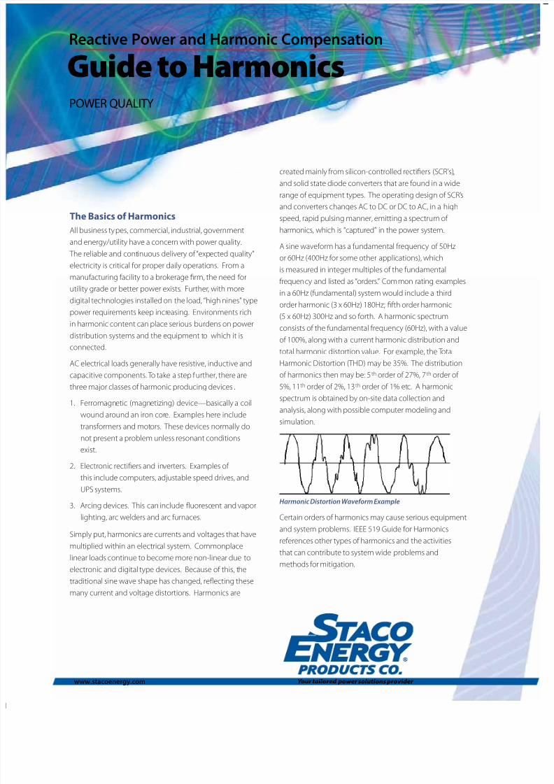
Industries WhereHarmonicsMay be Present■ Water Treatment■ Facilities■ Plastics/Coatings■ Glass Making■ Chemical Plant■ Steel Processing
■ Paper Processing■ Printing/Publishing■ Automotive■ Packaging■ Data Centers■ UPS Installations■ Petro/Chemical
www.stacoenergy.com
8/11/2019 StVAR GuideHarmonics Bro Prod
http://slidepdf.com/reader/full/stvar-guideharmonics-bro-prod 3/6
As an accepted guideline, voltage at a 5% THD limit at the point ofcommon coupling (PCC) is a practical recommendation. This valuegenerally refers to aggregate harmonics, helping to assure effi ciencyand reliability for industrial applications. Some electrical powerdistribution systems and connected equipment may function well athigher limits, and may require only minimal mitigation.
There are other devices which do not actually create harmonics, butrather magnify pre-existing harmonic currents. Capacitor systemsfall into this category, and it should be noted that capacitors donot create harmonics. When harmonic currents are injected intoa system in “parallel resonance,” the currents are magnied and
signicant voltage distortion can then result. Series resonance occurswhen capacitors are located near the end of feeder branches in thepower system. The capacitor acts as a low impedance to a particularharmonic current, almost like a tuned lter. Nuisance blown fuseconditions and capacitor degradation are possible. Harmonic currentsdue to non-linear loads generally ow from the load to the utilitysource. Sizing, designing and locating capacitor and lter productsinto the power system is critical for optimum performance
Other types of harmonics exist such as third and triplens (3 rd, 9th)orders where a neutral connection exists, and even orders (2 nd , 4th etc.) which are not a large concern due to low magnitudes and sub-harmonic orders. Staco Energy concentrates primarily on odd orderharmonic problems, which are found in a wide range of industrial andcommercial applications.
CausesEquipment widely used in offi ces and manufacturing not only createharmonic issues, but also are susceptible to harmonic disorders andproblems. Commonly found installations:
Computers (power supplies), PC, laptop, mainframe, servers
Monitors, video displays
Copiers, scanners, facsimile machines, printers, plotters
Lighting controls, dimmers
Electronic ballast
Communication systems, telephone, data transmission
Data centers, co-location facilities
UPS systems, battery chargers, storage systems
Standby and emergency generation, distributed generationsystems
Adjustable speed drives, drive systems
Transformers, generators
Arc electric furnaces, welding equipment
Medical and dental equipment
EffectsWhen these types of apparatus are operating daily, especially in a 24/7environment, both the equipment and systems may incur diffi culty
functioning properly from:Overheating of neutral conductors, bus bar, lug connections,mercury vapor and orescent lighting (electronic ballast), motorcontrol and switchgear, which may affect current interruptingcapabilities
Circuit breaker nuisance tripping, improper function of on-board breaker electronics, excessive arcing, improper fuseoperation or nuisance blown fuse interruption (articialheating, or “skin effect”)
AC motor torque pulsation, voltage sags, notching; DCadjustable speed drives creating high inrush currents
Overheating in transformers and cable systems, insulation(dielectric) breakdown
Power factor capacitors becoming overloaded, blown fuse,case swelling, insulation failure from excessive peak voltages,overheating due to high RMS currents
Effective use of power factor capacitors minimized, increasingcosts, potential for resonance conditions
Meter, protective relaying, control and other communication andmeasurement-instrumentation devices (including ground faultdetection and digital displays) malfunctioning or providing afaulty reading, mis-operation of electronic components and otherequipment
Communications (telephone, data, video) susceptible to noise,interference in motor controls, control systems, signal distortion
Lifespan of equipment can be reduced, potential for prematurefailure, downtime increased, higher maintenance costs, increase forpotential loss of specic production line or process, interruption inoperations, or catastrophic loss.
Your tailored power solutions provider
8/11/2019 StVAR GuideHarmonics Bro Prod
http://slidepdf.com/reader/full/stvar-guideharmonics-bro-prod 4/6
Application Requirements
User systems and their respective needs vary considerably. With thisin mind, it is necessary to collect specic information to fully assess
each application. Initial data should include:
Previous six to twelve months of electric utility billing data,contract, and tariffs agreements. This should also include ratestructure, load usage, kW/kVA, peak demand and power factorpenalty
Single line diagram of the building or facility, with all updates orrevisions
Plans for new capital equipment installations, general equipmentupgrades, facility expansion, or improvements
Most recent data from instrument measurements, site survey,general equipment and system notes, past electrical system
studies
To better understand the application requirements and assist withinitial system parameters, the following should be completed.
Primary voltage____________________ _______ _______ (line-to-line)
Secondary voltage _______________ ______ __________ (line-to-line)
System short circuit capability__________ _________ ______________
Transformer rating (kVA) _____________________ ________________
Transformer impedance (%) _________ _______ __________________
Wire/Cable/Bus Systems_________ _______ _____________________
Copper or aluminum____ _______ _____________________________
Ratings and size_________ ________ ___________________________
Length of runs, ways, systems and locations(provide single line with specic comments)
_________________________________________________________________
Installed EquipmentList each device or piece of equipment. Nameplate data and/orinstruction manuals should contain pertinent information. Offi ce
equipment, computer and communication systems should also beconsidered. For example:
Drive Type:
Manufacturer, H.P./kW, Amperes, kVA , PF Pulse (AC/DC)
Capacitor Type:
Manufacturer, kVAR, voltage, xed/switched, phases, how fused,minimum power factor present, maximum power factor, utility limit,and desired power factor, if applicable.
Communications:
Interface, tele/data, satellite
Other Considerations
What equipment, processes and operations are the most vulnerable?
Are there critical loads and a need for high nines power?
Have there been both long and short term outages?
Does a routine maintenance plan exist?
Have UPS, voltage regulation, generation, power distribution, motors/ drives, and other power quality equipment been evaluated to meetexisting and future expansion needs?
What are the costs for downtime, maintenance, scrap, lost production,return to uptime (waiting for parts, new equipment)?
Other Types of Installed Equipment
UPS Battery Chargers Rectiers
Motors Other Storage Systems Load Banks
Resistor Banks Furnaces HVAC
Generators Lighting Systems Compressors
Prime Power/DG Emergency/Standby Power
Upon collecting this information, an engineering service rm or
power quality consultant may be required to perform an analysis andsoftware generated modeling and equipment sizing study. Theremay be several solutions, which should be reviewed based upon theneed to correct an isolated problem, resolve system wide concerns,or development and implementation of a long-term power qualitystrategy.
www.stacoenergy.com
8/11/2019 StVAR GuideHarmonics Bro Prod
http://slidepdf.com/reader/full/stvar-guideharmonics-bro-prod 5/6
Applications primarily will be for three phase systems and involvethe installation of equipment at or near the harmonic producingload, or at the main incoming location. Most systems will havean acceptable balanced load; however, consideration should betaken for unbalanced/overload protection. Should capacitors inthe system fail (blown fuse), the remaining capacitors will need tofunction and absorb the system harmonic currents.
Consideration should also be given to the voltage rating ofcapacitors used in harmonic ltering applications. While capacitors
are designed to handle current and voltage levels in excess oftheir nameplate values, reduced life can be expected from normaloperation. When applied in a harmonic environment, capacitorswill be (voltage) overrated to accommodate the added stresses.
100-800 Amp Rating Load Pro le
Typical load proles found in commercial and industrial facilitiesencompass the following:
Basic commercial building or plant—lighting load (all types),personal computers, fax machines, copiers, telecommunications,HVAC, elevators, UPS equipment, panelboards and switchboards,
hospitals, both single and three phase power systems, existing andnew facilities.
800-2500 Amp Rating Load Pro le
Light to medium duty industrial facility—lighting loads (alltypes), personal computers, mainframe, servers, other offi ceequipment, tele-data and video communications, HVAC andenergy management systems, UPS equipment, panelboards,switchboards, switchgear with metering, protective relays,electronic circuit breakers, microprocessor based controls,LAN and various data network schemes, motor controlcenters, programmable logic controllers, machine controls,
motors, adjustable speed drives, including critical process andmanufacturing areas. New equipment, equipment upgrades andpotential for plant expansion.
2500 Amp and Above Rating Load Pro le
Same as above, plus the potential for “high duty” or “heavy”manufacturing needs such as arc furnaces, smelting, arc welders,robotic systems, dedicated machinery and factory automation,battery systems, racks and chargers, large power transformers,emergency and standby power, self-generation or distributedgeneration.
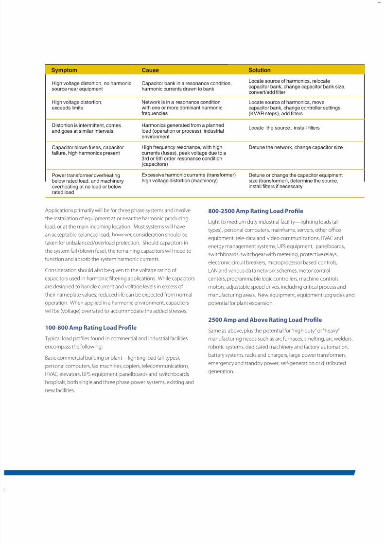
Symptom Cause Solution
High voltage distortion, no harmonicsource near equipment
High voltage distortion,exceeds limits
Distortion is intermittent, comesand goes at similar intervals
Capacitor blown fuses, capacitorfailure, high harmonics present
Power transformer overheatingbelow rated load, and machineryoverheating at no load or belowrated load
Capacitor bank in a resonance condition,harmonic currents drawn to bank
Network is in a resonance conditionwith one or more dominant harmonicfrequencies
Harmonics generated from a plannedload (operation or process), industrialenvironment
High frequency resonance, with highcurrents (fuses), peak voltage due to a3rd or 5th order resonance condition(capacitors)
Excessive harmonic currents (transformer),high voltage distortion (machinery)
Locate source of harmonics, relocatecapacitor bank, change capacitor bank size,convert/add lter
Locate source of harmonics, movecapacitor bank, change controller settings(KVAR steps), add lters
Locate the source , install lters
Detune the network, change capacitor size
Detune or change the capacitor equipmentsize (transformer), determine the source,install lters if necessary
8/11/2019 StVAR GuideHarmonics Bro Prod
http://slidepdf.com/reader/full/stvar-guideharmonics-bro-prod 6/6
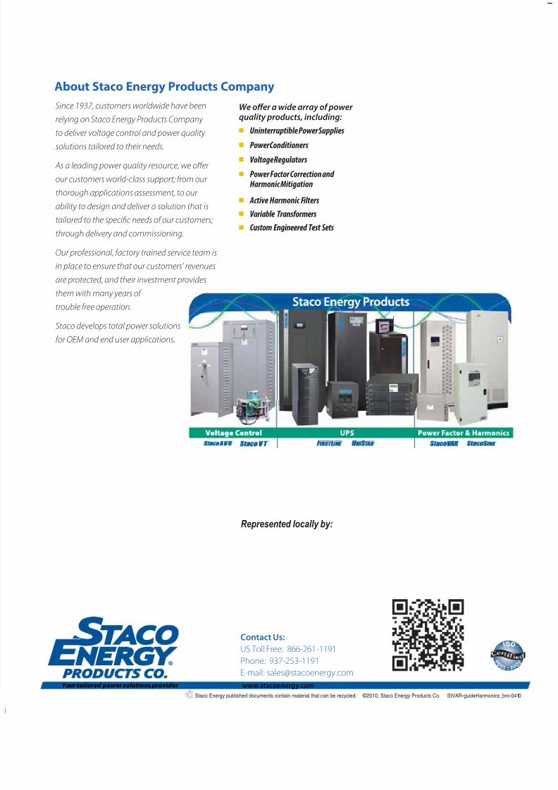
Since 1937, customers worldwide have beenrelying on Staco Energy Products Companyto deliver voltage control and power qualitysolutions tailored to their needs.
As a leading power quality resource, we offerour customers world-class support; from ourthorough applications assessment, to ourability to design and deliver a solution that istailored to the specic needs of our customers;through delivery and commissioning.
Our professional, factory trained service team isin place to ensure that our customers’ revenues
are protected, and their investment providesthem with many years oftrouble free operation.
Staco develops total power solutionsfor OEM and end user applications.
We offer a wide array of powerquality products, including:■ Uninterruptible Power Supplies■ Power Conditioners■ Voltage Regulators■ Power Factor Correction and
Harmonic Mitigation
■ Active Harmonic Filters■ Variable Transformers■ Custom Engineered Test Sets
Contact Us:US Toll Free: 866-261-1191Phone: 937-253-1191E-mail: [email protected]
About Staco Energy Products Company
Represented locally by:
Staco Energy published documents contain material that can be recycled. © 2010, Staco Energy Products Co. StVAR-guideHarmonics_bro-0410
www.stacoenergy.comYour tailored power solutions provider