Embed Size (px)
Citation preview
SUBJECT CODE : EE6703
SUBJECT NAME : Special Electrical Machines
STAFF NAME : Mr.U.Nagabalan
INTRODUCTION
SYNCHRONOUS RELUCTANCE MOTOR -
- It is similar to the salient pole synchronous machine except that the rotor does not have any field winding.
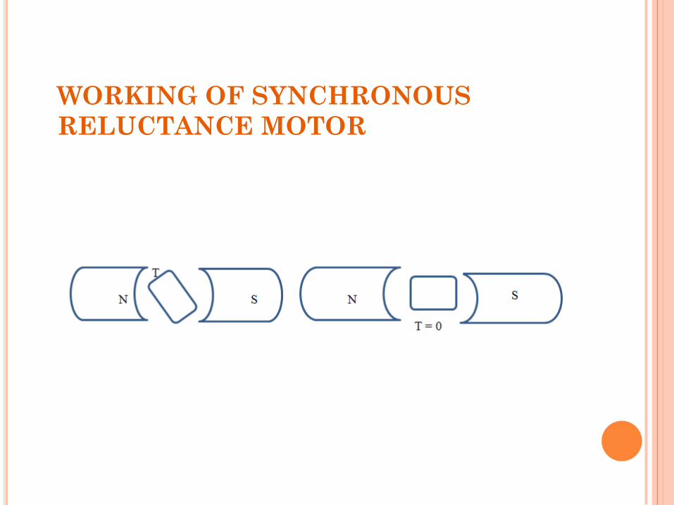
RELUCTANCE TORQUE -- The tendency of the salient poles to align themselves in the minimum reluctance position.
FLUX BARRIER -- It is another approach is to use laminations. The lamination required for the shaft weaken the rotor .It is used for low speed design.
AXIAL AIR GAP MOTOR -- It is another approach is to use laminations. The torque ripple and iron losses are more in axially laminated rotor than radiallylaminated.
INTRODUCTION
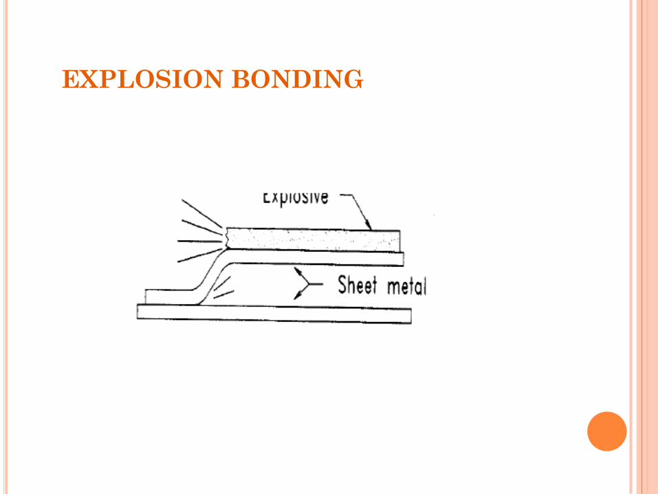
EXPLOSION BONDING -- First sheets of
ferromagnetic and nonmagnetic steel are bonded .The
bonded sheets are then cut into rectangular blocks which
are the machined into the desired rotor.
SALIENT ROTOR -- Salient rotor shape such that
the quadrature air gap is much larger than the direct air
gap. It is used for high speed application.
CONSTRUCTION OF SYNCHRONOUS
RELUCTANCE MOTOR
CONSTRUCTION OF SYNCHRONOUS
RELUCTANCE MOTOR
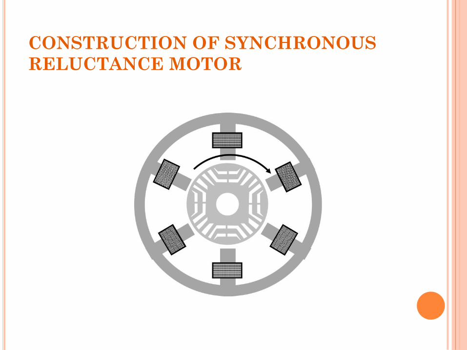
The stator has three phase symmetrical
winding, which creates sinusoidal rotating
magnetic field in the air gap.
Reluctance torque is developed because the
induced magnetic field in the rotor has a
tendency to cause the rotor to align with the
stator field at a minimum reluctance position
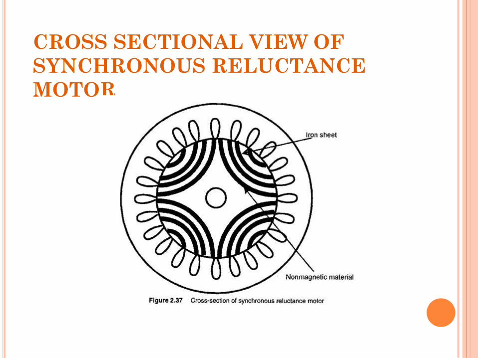
CROSS SECTIONAL VIEW OF
SYNCHRONOUS RELUCTANCE
MOTOR
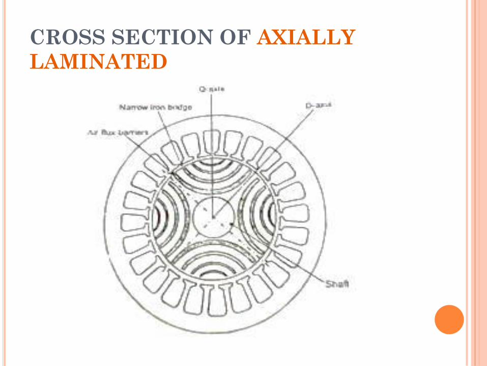
CROSS SECTION OF AXIALLY
LAMINATED
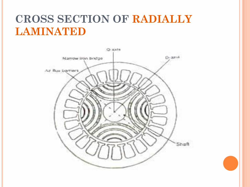
CROSS SECTION OF RADIALLY
LAMINATED
CONSTRUCTION OF SYNCHRONOUS
RELUCTANCE MOTOR
ROTOR DESIGN
Salient rotor (Segmental)
Radially Laminated Rotor (Flux Barrier)
Axially Laminated Rotor
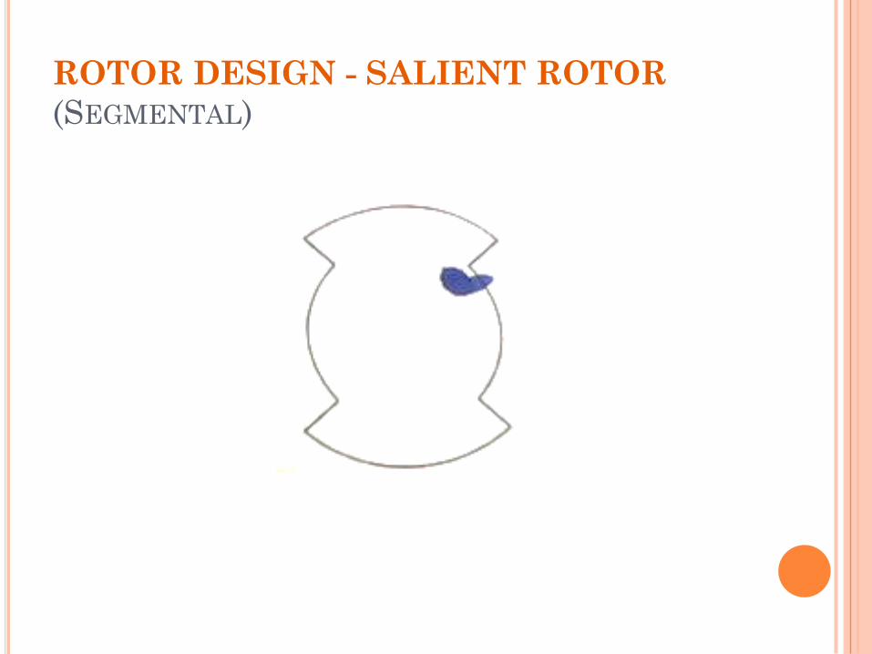
ROTOR DESIGN - SALIENT ROTOR
(SEGMENTAL)
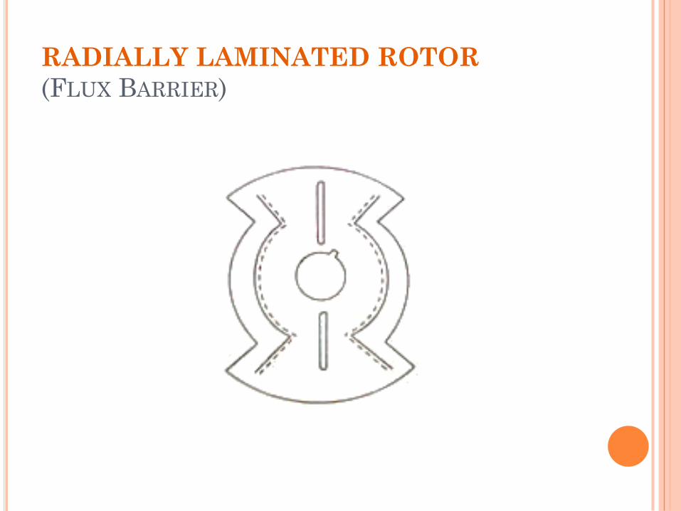
RADIALLY LAMINATED ROTOR
(FLUX BARRIER)
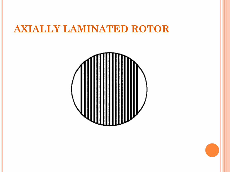
AXIALLY LAMINATED ROTOR
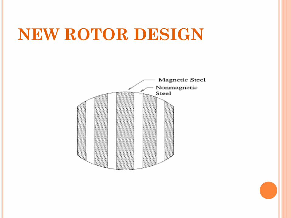
NEW ROTOR DESIGN
EXPLOSION BONDING
WORKING OF SYNCHRONOUS
RELUCTANCE MOTOR
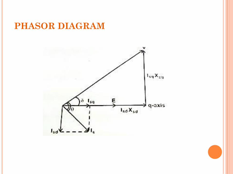
PHASOR DIAGRAM
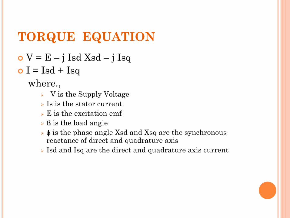
TORQUE EQUATION
V = E – j Isd Xsd – j Isq
I = Isd + Isq
where., V is the Supply Voltage
Is is the stator current
E is the excitation emf
Ȣ is the load angle
ɸ is the phase angle Xsd and Xsq are the synchronous reactance of direct and quadrature axis
Isd and Isq are the direct and quadrature axis current
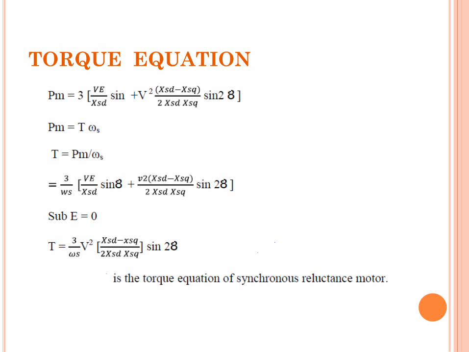
TORQUE EQUATION
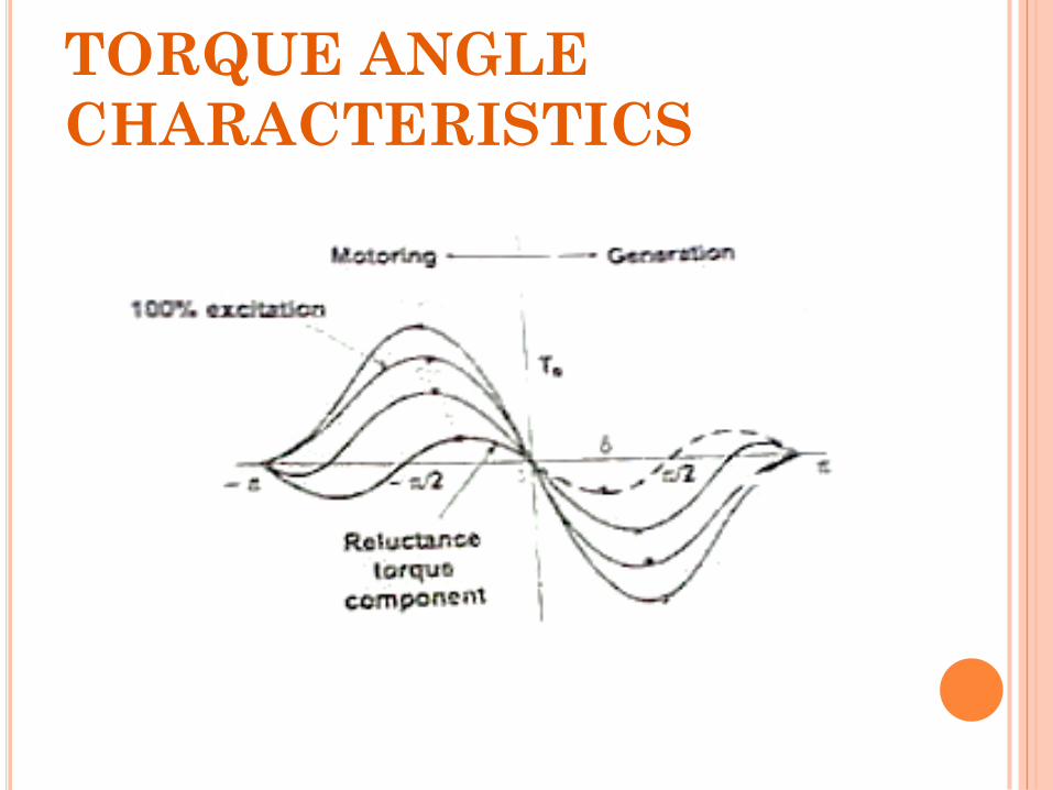
TORQUE ANGLE
CHARACTERISTICS
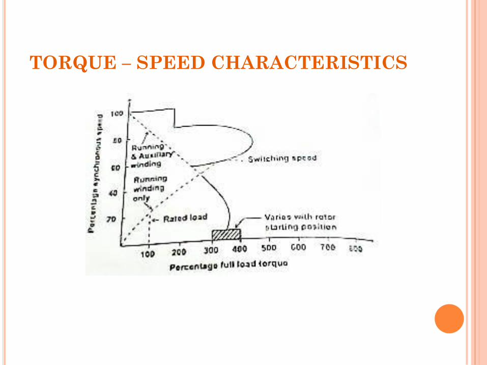
TORQUE – SPEED CHARACTERISTICS
ADVANTAGES & DISADVANTAGES ADVANTAGES
There is no concern with demagnetization; hence synchronous reluctance machines are inherently more reliable than PM machines.
There need not be any exciting field as torque is zero, thus eliminating electromagnetic spinning losses.
Synchronous reluctance machine rotors can be constructed entirely from high strength, low cost materials.
DISADVANTAGES
High cost than induction Motor.
Need Speed synchronization to invertor output frequency by using rotor position sensor and sensor less control.
Compared to induction motor it is slightly heavier and has low power factor.
By increasing the saliency ratio Lds/Lqs, the power factor can be improved.
APPLICATIONS
Metering pumps.
Auxiliary time mechanism.
Wrapping and folding machines.
Proportioning devices on pumps or conveyors.
Synthetic fiber manufacturing equipment.
Processing continuous sheet or film material.
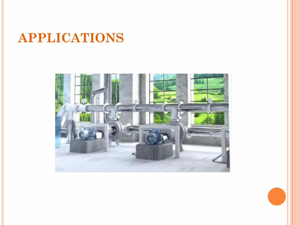
APPLICATIONS
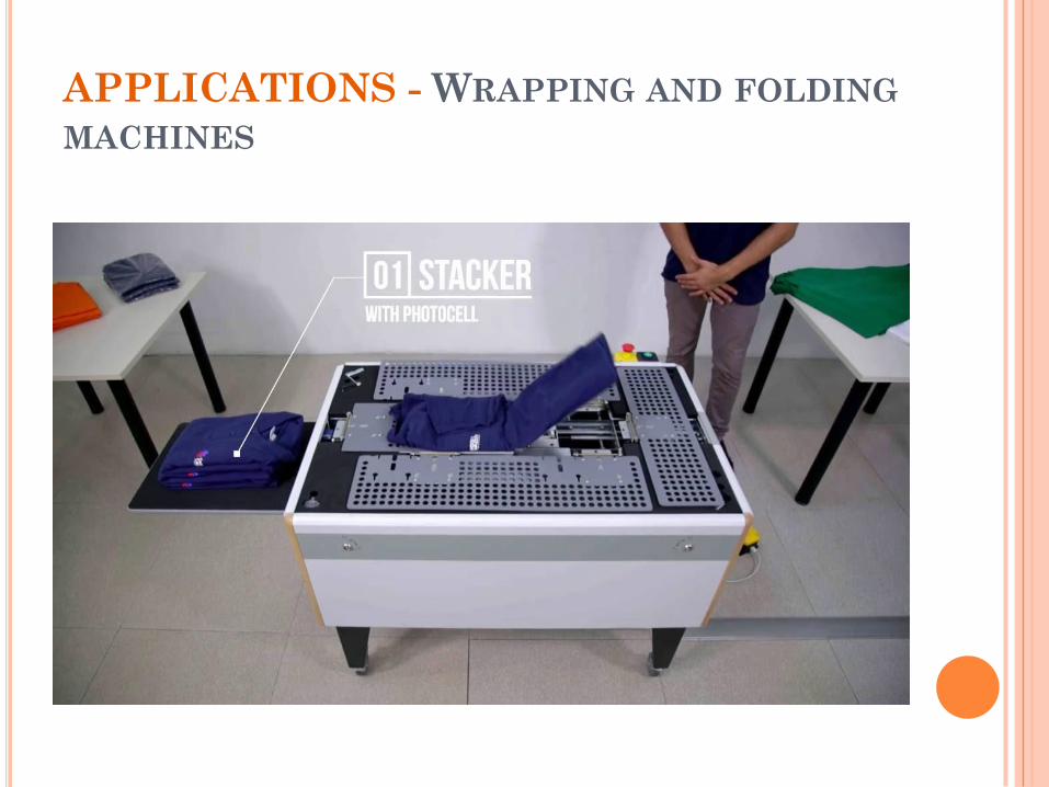
APPLICATIONS - WRAPPING AND FOLDING
MACHINES