Embed Size (px)
Citation preview
Submersible Pump Stand for Lake Applications
DescriptionThis pump stand is designed to suit many types of submersible pumps. It may be adjusted in the field to suit various conditions or requirements.For technical support call Heat-Line at (800) 584-4944.
Tools Required• Pailorbucket
Additional Materials Required• ABSCement• PremixedConcrete• FlexibleconduitorBig"O"
InStALLAtIon InStructIonS
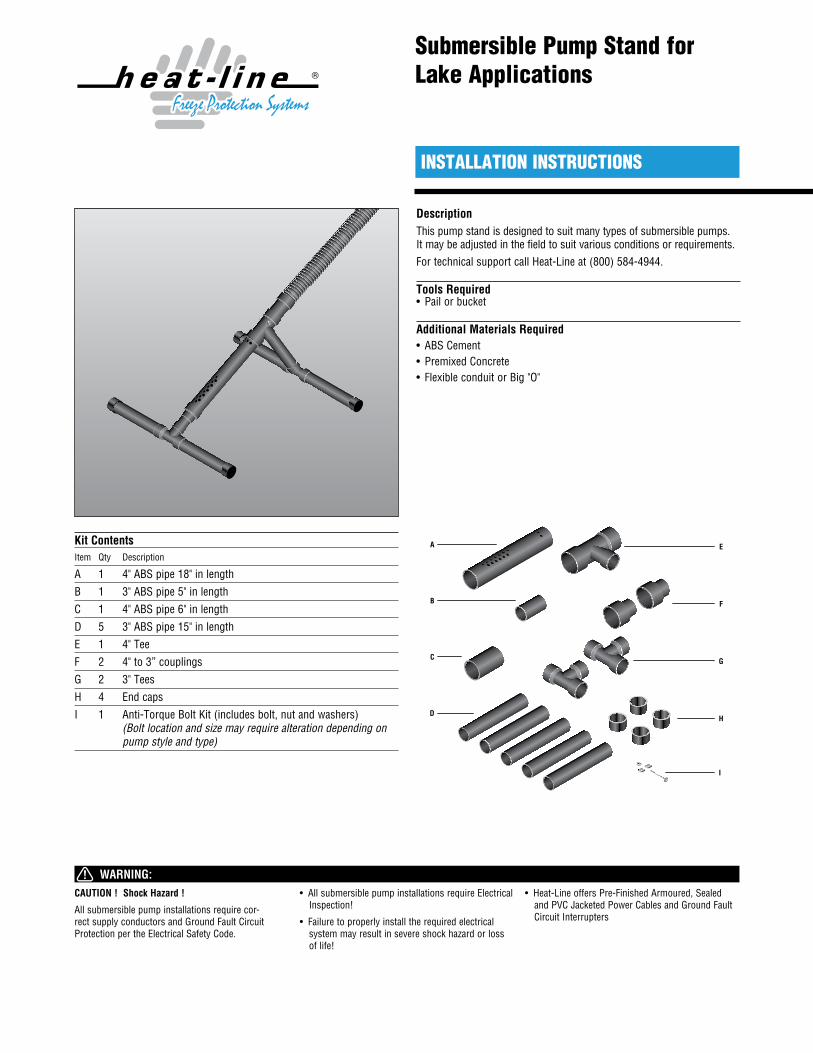
Kit ContentsItem Qty Description
A 1 4"ABSpipe18"inlength
B 1 3"ABSpipe5"inlength
C 1 4"ABSpipe6"inlength
D 5 3"ABSpipe15"inlength
E 1 4"Tee
F 2 4"to3”couplings
G 2 3"Tees
H 4 End caps
I 1 Anti-TorqueBoltKit(includesbolt,nutandwashers) (Bolt location and size may require alteration depending on pump style and type)
A
B
C
D
F
E
G
H
I
CAUTION ! Shock Hazard !
Allsubmersiblepumpinstallationsrequirecor-rectsupplyconductorsandGroundFaultCircuitProtectionpertheElectricalSafetyCode.
• AllsubmersiblepumpinstallationsrequireElectricalInspection!
• Failuretoproperlyinstalltherequiredelectricalsystemmayresultinsevereshockhazardorlossof life!
• Heat-LineoffersPre-FinishedArmoured,SealedandPVCJacketedPowerCablesandGroundFaultCircuitInterrupters
Tee(pointing down)
Pipe (withholes upward)
ABScement
Submersible Pump Stand for Lake Applications Installation Instructions
2
4" to 3" Reducer (Part F)
4" to 3" reducer (Part F)
Set asidefor last stepsequence
3" to 5" Pipe (Part B)
4" X 6" Pipe (Part C)
4" to 3" Tee (Part E)
4" X 18" Pipe (Part A)
Body Assembly
Leg Assembly
Tee(pointing
down)
Pipe (withholes upward)
3" X 15" Pipe (Part D)
End cap (Part H)
Tee - 3" X 3" X 3" (Part G)
ABScement
Pre-mixconcrete
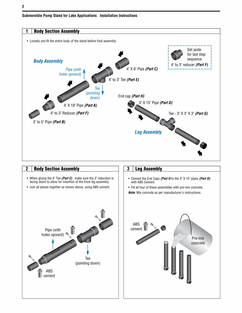
1 Body Section Assembly
Body Section Assembly Leg Assembly3
• Looselypre-fittheentirebodyofthestandbeforefinalassembly.
• CementtheEndCaps(Part Htothe3"X15"pipes(Part D) withABSCement.
• Fillallfouroftheseassemblieswithpre-mixconcrete.
Note: Mixconcreteaspermanufacturer'sinstructions.
2
• Whengluingthe4"Tee(Part E),makesurethe3"reductionisfacingdowntoallowforinsertionofthefrontlegassembly.
• Joinallpiecestogetherasshownabove,usingABScement.
Submersible Pump Stand for Lake Applications Installation Instructions
3
ABScement
3" X 15" pipe(Part D)
3" X 15"leg assemblies
(filled with concrete)
Tee - 3" X 3" X 3"(Part G)
ABScement
ABScement
Front LegAssemblyBack Leg
Assembly
BodyAssembly
54
6 7
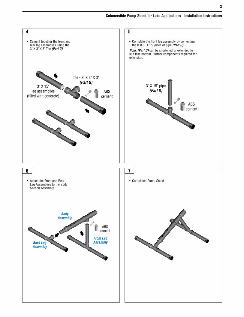
• Completethefrontlegassemblybycementingthelast3"X15"pieceofpipe(Part D).
Note: (Part D) canbeshortenedorextendedtosuitlakebottom.Furthercomponentsrequiredforextension.
• Cementtogetherthefrontandrear leg assemblies using the 3"X3"X3"Tee(Part G) .
• AttachtheFrontandRearLegAssembliestotheBodySectionAssembly.
• CompletedPumpStand
Submersible Pump Stand for Lake Applications Installation Instructions
4
Heat-Line A division of Christopher MacLean Ltd.1095GreenLakeRoadCarnarvon,ONCanada K0M1J0Tel: (705) 754-4545 (800) 584-4944Fax:(705)[email protected]
Important: All information, including illustrations, is believed to be reliable. Users, however, should independently evaluate the suitability of each product for their particular application. Heat-Line a Division of Christopher MacLean Ltd. makes no warranties as to the accuracy or completeness of the information, and disclaims any liability regarding its use. Heat-Line's only obligations are those in the Heat-Line Standard Terms and Conditions of Sale for this product, and in no case will Heat-Line be liable for any incidental, indirect, or consequential damages arising from the sale, resale, use, or misuse of the product. Specifications are subject to change without notice. In addition, Heat-Line reserves the right to make changes—without notification to Buyer—to processing or materials that do not affect compliance with any applicable specification.
Heat-LineisaregisteredtrademarkofHeat-LineCorporation.
©2014Heat-L
ineadivisionofC
hristopherM
acLeanLtd.06/14
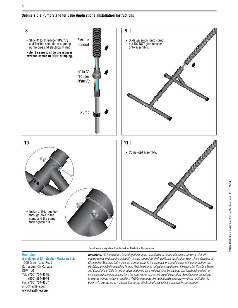
Flexibleconduit
4" to 3"reducer(Part F)
Pump
8
10 11
9
• Slide4"to3"reducer(Part F) andflexibleconduitontopump,pumppipeandelectricalwiring.
Note: Be sure to slide the reducer over the cables BEFORE crimping.
• Installanti-torqueboltthrough hole in the standandthepump,then tighten nut.
• Completedassembly.
• Slideassemblyontostand,butDONOTgluereduceronto assembly.