Embed Size (px)
Citation preview
S:\4808.00\4808.02\ADDENDUM\#2\4808 ADDENDUM 1 TRANS LETTERHEAD 3-4-2021.DOCX
March 4, 2021 TO ALL HOLDERS OF PLANS AND SPECIFICATIONS: RE: COMMISSION BOULEVARD WATER TREATMENT PLANT (DSA No. 4808.02) ATTENTION: Attached is ADDENDUM NO. 2 for the subject project. Please include it in your set of specifications and consider it when making your bid. Sincerely, DOMINGUE, SZABO & ASSOCIATES, INC. ^ Chris Richard, PE CKR/ Enclosure(s)
102 Asma Boulevard Suite 305
Lafayette, LA 70508
(337)232-5182 FAX (337)237-7132
www.dsaengineering.com
3/4/2021
4808.02 1 Addendum No. 2
ADDENDUM TO CONTRACT DOCUMENTS
AND SPECIFICATIONS
COMMISSION BOULEVARD WATER TREATMENT PLANT (DSA No. 4808.02)
ADDENDUM NO. 2 March 4, 2021
The following items shall take precedence over referenced to counterparts in the specifications, contract drawings and any other documents in conflict herewith. Item No. 1 Refer to the Specifications and Contract Documents, ADD the attached Section
02830 – Chain Link Fencing and Gates to the contract documents. Item No. 2 Refer to the Specifications and Contract Documents, Section 07200 – Insulation,
• Change LAMTEC Insulation to LAMTEC WMP-50 • Roof insulation is 8” with retainer clips at 24”. • Insulation shall be secured using retainer clips with color matching the
insulation facing. Item No. 3 Refer to the Specifications and Contract Documents, Section 08120 – Aluminum
Flush Doors and Frames. As a Note of CLARIFICATION; Exterior doors and all doors at the Chlorine Building shall be aluminum doors in accordance with Section 08120. Interior doors in the Filter Building shall be in accordance with the attached SECTION 08100 - STEEL DOORS, TRANSOMS AND FRAMES.
Item No. 4 Refer to the Specifications and Contract Documents, Section 08522 – Aluminum
Windows, REPLACE with the attached Section 08522 Aluminum-Framed Storefronts and Vent Windows.
Item No. 5 Refer to the Specifications and Contract Documents, Section 09900 – Painting,
ADD the following paint schedule for the ground storage tank
Prestressed Concrete Tanks: Exterior
Surface Preparation: Minimum of 14 days cure time. Clean surface with high pressure water blasting prior to coating to remove all soluble surface contaminants. Surface shall be clean and dry prior to coating.
Coating: 1st Coat - Tnemec Series 156 Envirocrete 4 to 6 mils dry film thickness 2nd Coat - Tnemec Series 156 Envirocrete 4 to 6 mils dry film thickness MIN. 10 MILS TOTAL DRY FILM THICKNESS
4808.02 2 Addendum No. 2
Item No. 6 Refer to the Specifications and Contract Documents, ADD the attached Section 11130 – Cylinder Hoist and Trolley to the contract documents. Refer to Electrical for power requirements.
Item No. 7 Refer to the Specifications and Contract Documents, Section 11500 – IRON
AND MANGANESE FILTRATION SYSTEM – HORIZONTAL PRESSURE FILTERS, ADD each filter cell will be equipped with a 2” drain connection and ball valve on the effluent line to drain the tank. Each valve will be equipped with a 2” cam-lok fitting with dust cap.
Item No. 8 Refer to the Specifications and Contract Documents, Section 11550 –
BIOLOGICAL – HORIZONTAL PRESSURE FILTERS, ADD each filter cell will be equipped with a 2” drain connection and ball valve on the effluent line to drain the tank. Each valve will be equipped with a 2” cam-lok fitting with dust cap.
Item No. 9 Refer to the Specifications and Contract Documents, Section 13100 –
PRESTRESSED COMPOSITE TANK (TYPE II TANK), As a Note of CLARIFICATION; there is no interior coating system for the ground storage tank.
Item No. 10 Refer to the Plans, Sheet A4.1: CHANGE reference to wire glass to Firelite NT
in fire rated doors. Item No. 11 Refer to the Plans, Sheet 19 As a Note of CLARIFICATION:
• Windows shown on the floor plan should read “A” for all exterior windows except the one window in exterior wall of office 104 should read “B” Window labeled “2” should read “C”
• Delete reference to door types in the floor plan. Refer to Sheet A3.1 for correct door types.
Item No. 12 Refer to the Plans, Sheets 21, 22, 23 & 25; DELETE - 4” Greensand Plus drain
piping and valves from each filter cell to the drain. Filters will not be equipped with the freeboard drains.
Item No. 13 Refer to the Plans, Sheet 30. As a Note of CLARIFICATION; Interior baffle
wall is to be provided by tank contractor. Item No. 14 Refer to the Plans, Sheet 30 Detail 4. Tank Contractor can substitute cast-in-
place concrete or shot-crete baffle wall in lieu of the CMU wall as shown. Item No. 15 Refer to the Plans, Sheet 30 As a Note of CLARIFICATION An interior
ladder is required at each hatch location. Item No.16 Refer to the Plans, Sheet 31. As a Note of CLARIFICATION; Manway is
hinged with a smooth nozzle sample tap. Item No. 17 Refer to the Plans, As a General Note; 3” galvanized pipe can be used in lieu of
the 3 ½” galvanized drain pipe shown from the filter air release valve discharge.

4808.02 3 Addendum No. 2
Item No. 18 See attached items from the Electrical Engineer. Item No. 19 PRIOR APPROVAL LIST: The following manufacturers’ equipment may be
considered for use on this project (they have received prior approval subject to the following):
The Engineer may allow minor deviations subject to the Engineer’s judgment as to whether such deviations would detract from the quality, reliability or function of the equipment. The equipment manufacturer shall be responsible for any and all redesign required to accommodate their equipment. All drawings and calculations detailing the deviations from the plans and specifications shall be submitted to the Engineer with the shop drawings for approval. Drawings must be in AutoCad 2019 or more recent format and must be stamped by an Engineer licensed in the State of Louisiana. Submit both hard copies and electronic copies for approval. Prior approval of other manufacturers’ equipment shall in no way relieve the Contractor of responsibility for submitting the specified shop drawings for approval or complying fully with ALL provisions of the specifications and drawings.
If prior approved equipment is used, the contractor shall, at his own expense, make any changes or additions in the structures, piping, electrical, etc. as necessary to accommodate the equipment. If engineering is required due to substitution of prior approved equipment, the contractor shall furnish and pay for all such engineering services. No qualifications or exceptions listed in prior approval submittals shall in any way alter or serve as substitute provisions relative to this contract.
Section Description of Items Approved Mfr. 02719 Air Release Valves ClaVal Model 33 02719 Check Valves Milliken
11300 Vertical Turbine Pumps Hydroflo High Service
11305 Vertical Turbine Pumps Hydroflo
Backwash Supply Pumps
4808.02 4 Addendum No. 2
RESPOND TO EMAIL ACKNOWLEDGING RECEIPT OF ADDENDUM
End of Addendum No. 2
4808.02 1 02830
SECTION 02830 - CHAIN LINK FENCING AND GATES PART 1 - GENERAL: RELATED DOCUMENTS: Drawings and general provisions of the Contract, including General and Special Conditions and Division 1 Specification sections apply to the work of this section. Electrical service, description of control, and connections for gate operators: See Section 16710 “Access Control System”, and the control diagrams in the drawings. DESCRIPTION OF WORK: CHAIN LINK FENCING AND GATES Extent of chain link fences and gates is shown on drawings including tie-ins to existing chain link fences to remain. VEHICULAR SLIDE GATE OPERATOR/CONTROLLER Vehicular slide gate operator, complete with all drive and electrical components, to move gate and control its position in both the open and close directions. A complete system is required and the Contractor shall furnish all materials, equipment and labor necessary to operate the gate as specified in this section. The General Contractor shall coordinate between the sliding gate supplier, gate operator manufacturer, gate operator installer, and electrical/control contractors to ensure that a complete, working system is furnished. All concrete pads, concrete foundations, mounting posts, hardware, equipment, materials, and other items necessary for a complete, working system shall be included in the bid. QUALITY ASSURANCE: Provide chain link fences and gates as complete units controlled by a single source including necessary erection accessories, fittings, and fastenings. Gate operator system shall conform to:
1. UL325: Standard for door, drapery, gate, louver, and window operators and systems.
2. UL991: Standard for testing of solid-state control devices. Gate Operator Installer shall complete all electrical work in accordance with all local codes and follow the guidelines of National Electrical Code. All fieldwork shall be performed in a neat and professional manner. Gate Operator Manufacturer shall be a company specializing in the design and manufacture of door and gate operators, with a minimum of ten years of experience.
4808.02 2 02830
Gate Operator Installer shall be a company certified as a dealer of the manufacturer within qualifying industries, such as fence, security, ornamental iron, or parking, with expertise in installation of gate operators. Gate Operator Installer shall store product upright in the original shipping containers, covered and protected from all weather conditions. GATE OPERATOR FACTORY INSPECTION AND TESTING
A. Manufacturer shall test each operator at factory to assure smooth, quiet operation. B. Manufacturer shall test all control inputs to ensure proper function.
GATE OPERATOR WARRANTY
A. Gate Operator and all accessories (the system) shall be warranted by the manufacturer for a period of two years from date of final acceptance of the project against defects in materials or workmanship. Defective part(s) shall be repaired or replaced at no charge, at the manufacturer’s option.
SUBMITTALS: Product Data: Submit manufacturer's technical data, and installation instructions for metal fencing and gates. Gate Operator Submittals:
A. Installation manuals: manufacturer shall supply a copy with each operator, detailing all necessary mounting instructions, wiring connections, parts lists, maintenance, and troubleshooting.
B. Owner’s information sheet: a separate owner’s information sheet shall also be supplied with the installation manual.
C. Wiring diagram: manufacturer shall supply a wiring connections diagram with each operator. The wiring diagrams shall be integrated with the access controls provided under other sections of the specifications.
D. Safety literature: manufacturer shall supply a copy of its safety literature with each operator.
E. Warning signs: manufacturer shall supply warning signs, in compliance with requirements of UL325.
F. Shop drawings: shop drawings shall be supplied by the manufacturer upon installer request.
4808.02 3 02830
PART 2 - PRODUCTS GENERAL: Dimensions shown for pipe, roll-formed, and H-sections are outside dimensions. STEEL FENCING: Fabric : No. 9 ga. (0.148") finished size steel wires, 2" mesh, with top salvages knuckled for fabric 60" high and under, and both top and bottom selvages twisted and barbed for fabric over 60" high.
Fabric finish- galvanized, ASTM A392, Class II, with not less than 2.0 oz. zinc per sq. ft. of surface.
Framework: Galvanized steel, ASTM A120 or A123, with not less than 1.8 oz. zinc per sq. ft. of surface. Hardware and Accessories: Galvanized, ASTM A152, with zinc weights. FRAMING AND ACCESSORIES: Refer to the plans for information on end, corner, and line posts. Gate Posts: Refer to the plans for information on gate posts. Top Rail: Manufacturer's longest lengths, with expansion type couplings, approximately 6" long, for each joint. Provide means for attaching top rail securely to each gate corner, pull and end post. 1.66" OD pipe, 2.27 lbs. per ft. or 1.625" x 1.25" roll-formed sections, 1.35 lbs. per ft. Tension Wire: 7 gauge, coated coil spring wire, metal and finish to match fabric. Post Brace Assembly: Manufacturer's standard adjustable brace at end and gate posts and at both sides of corner and pull posts, with horizontal brace located at mid-height of fabric. Use same material as top rail for brace, and truss to line posts with 0.375" diameter rod and adjustable tightener. Post Tops: Weathertight closure cap (for tubular posts), one cap for each post. Barbed Wire Supporting Arms: Manufacturer's standard barbed wire supporting arms, metal and finish to match framework, with provision for anchorage to posts and attaching 3 rows of barbed wire to each arm. Supporting arms may be either attached to posts or integral with post top weather cap and must be capable of withstanding 250 lbs. downward pull at outermost end. Provide following type:
4808.02 4 02830
Barbed Wire: 2 strand, 12 - ½ ga. wire with 14 ga. 4-point barbs spaced not more than 5" o.c.; metal and finish to match fabric. Stretcher Bars: One-piece lengths equal to full height of fabric, with minimum cross-section of 3/16" x 3/4". Provide one stretcher bar for each gate and end post, and 2 for each corner and pull post, except where fabric is integrally woven into post. Stretcher Bar Bands: Space not over 15" o.c., to secure stretcher bars to end, corner, pull, and gate posts. Gates: Fabricate swing gate perimeter frames of 1.90" OD pipe. Metal and finish to match framework. Provide horizontal and vertical members to ensure proper gate operation and for attachment of fabric, hardware and accessories. Space so that frame members are not more than 8' apart. Gate Hardware: Furnish the following hardware and accessories for each gate.
Hinges: Size and material to suit gate size, non-lift-off type, offset to permit 180o gate opening. Provide 1- ½ pair of hinges for each leaf over 6' nominal height. Latch: Forked type or plunger-bar type to permit operation from either side of gate, with padlock eye as integral part of latch. Keeper: Provide keeper for vehicle gates, which automatically engages gate leaf and holds it in open position until manually released. Double Gates: Provide gate stops for double gates, consisting of mushroom type of flush plate with anchors. Set in concrete, to engage center drop rod or plunger bar. Include locking device and padlock eyes as integral part of latch, using one padlock for locking both gate leaves.
Sliding Gates: See drawings.
Wire Ties: For tying fabric to line posts, use wire ties spaced 12" o.c. For tying fabric to rails and braces, use wire ties spaced 24" o.c. For tying fabric to tension wire, use hog rings spaced 24" o.c. Vehicular Slide Gate Operator/Controller: Slide gate operator shall be Model GSLG-A-4 as manufactured by Operator Specialty Company, Inc. (OSCO). Operator shall open and close the cantilever gate at the entrance to the treatment plant site. This gate operator must function with the specified accessories including radio controls. The gate operator shall be supplied 120/208 Volt AC single-phase power. Control voltage shall be 24 Volt DC. Radio control of the gate operator shall be provided under this section of the specifications. The gate operator shall accept dry contract closures from several sources as commands to open. Refer to electrical specifications and the riser and control
4808.02 5 02830
diagrams in the electrical drawings for information regarding operation and control of the gate operator. Interposing relays (24 VDC) shall be provided for each external command. The gate operator shall provide a dry contact closure for external use indicating presence of a vehicle over the street side entry loop detector. The Contractor is cautioned that special operation and controls are required. This is not a standard installation. Gate Operator Design Criteria: Operation shall be by means of a ¾ horsepower single-phase C-faced instant reversing motor, transferring power to a heavy-duty right angle oil bath gear reducer. Power shall be transferred from the gear reducer to a heavy-duty 5-inch diameter torque limiter and #40 plate sprocket. From the torque limiter power shall be transferred to the output drive shaft equipped with a #50 drive sprocket and roller chain which shall attach to the gate with heavy-duty gate attachment brackets. Gate Operator Components:
A. Standard mechanical components shall include as a minimum: 1. 14 gauge weather-resistant stainless steel cabinet. 2. Gasketed cabinet door that is removable and lockable. 3. Heavy-duty right angle oil bath C-face gear reducer. 4. 1-inch solid steel output drive shaft. 5. Heavy-duty pillow block bearings with grease fittings for easy maintenance. 6. Heavy-duty 5-inch diameter torque limiter. 7. Dual C-face 6 foot-pound brake. 8. Spring-loaded manual disconnect. 9. All welded interior steel framework.
B. Standard electrical components shall include as a minimum:
1. 3/4 HP motor with thermal overload protection in 208 VAC single-phase. 2. Solid-state logic controls featuring 15 diagnostic L.E.D. indicators and auto-close
timer (0 to 124 seconds). 3. Inherent, adjustable motor over-current sensing to detect obstructions, with
separate adjustments for opening and closing directions. 4. Controller housed in zinc plated control box. 5. Power On/Off switch. 115 VAC duplex outlets shall be included. 6. Contacts for opening, closing and reversing accessories, as well as contact and
non-contact obstruction sensing devices. 24 VAC and 24 VDC shall be available on terminal strip to power accessory devices.
7. Adjustable limits with precision snap-action type limit switches to control gate position.
8. Master/slave or stand alone capable with dip switch selection. Three wire twisted pair shielded cable required.
C. Accessories, contact, non-contact, and control devices:
1. Control devices shall include radio controls and an “OPEN-AUTO” selector switch for opening the gate for prolonged periods of time.
2. Contact devices shall include contact edges.
4808.02 6 02830
D. Other provided options shall include:
1. Stainless steel cabinet. 2. Thermostatically controlled 125 watt strip heater with auto/off/manual control
switch. Concrete: Refer to Division 3. PART 3 - EXECUTION Fencing and Gates: INSTALLATION: Do not begin installation and erection before final grading is completed, unless otherwise permitted. Excavation: Drill holes for posts of diameters and spacings shown, in firm, undisturbed or compacted soil. Setting Posts: Center and align posts in holes 6" above bottom of excavation. Top Rails: Run rail continuously through post caps, bending radius for curved runs. Provide expansion couplings as recommended by fencing manufacturer. Brace Assemblies: Install braces so posts are plumb when diagonal rod is under proper tension. Tension Wire: Install tension wires before stretching fabric and tie to each post with not less than 6 ga. galvanized wire. Fasten fabric to tension wire using 11 ga. galvanized steel hog rings spaced 24" o.c. Fabric: Leave approximately 2" between finish grade and bottom selvage, unless otherwise indicated. Pull fabric taut and tie to posts, rails, and tension wires. Install fabric on security side of fence, and anchor to framework so that fabric remains in tension after pulling force is released. Stretcher Bars: Thread through or clamp to fabric 4" o.c., and secure to posts with metal bands spaced 15" o.c. Barbed Wire: Pull wire taut and fasten securely to extension arms in accordance with manufacturer's instructions. Gates: Install gates plumb, level, and secure for full opening without interference. Install ground-set items in concrete for anchorage, as recommended by fence manufacturer. Adjust hardware for smooth operation and lubricate where necessary.
4808.02 7 02830
Tie Wires: Use U-shaped wire, conforming to diameter of pipe to which attached, clasping pipe and fabric firmly with ends twisted at least 2 full turns. Bend wire to minimize hazard to persons or clothing. Fasteners: Install nuts for tension bands and hardware bolts on side of fence opposite fabric side. Peen ends of bolts or score threads to prevent removal of nuts. The fence shall be grounded by a copperweld rod eight feet (8') long and a minimum of 5/8" in diameter, driven vertically until the top of it is approximately six inches (6") below the top of the ground. A No. 6 solid copper conductor shall be brazed to the rod and to the fence in such a manner that each element of the fence is grounded. Where a power line passes over the fence, a ground shall be installed immediately below the point of crossing. Otherwise, ground shall be spaced along the fence at intervals of five hundred feet (500') (maximum). No special payment will be made for electrical grounds, and the cost thereof shall be included in the prices bid for fence and gates under these items. Vehicular Slide Gate Operator: The gate operator installer shall become familiar with the installation of the specified model of operator and shall review the necessary adjustments for configuring the operator prior to commencement of installation. INSPECTION: The installer shall inspect the site prior to installation to confirm that manufacturer’s instructions can and shall be followed. Contact the manufacturer with any questions or to request special instructions if standard installation is not possible. INSTALLATION: The installer shall install the operator in accordance with the manufacturer’s written instructions, referencing all dimensional schematics and shop drawings provided. The installer shall contact the manufacturer’s technical support department should additional assistance be required. The installer shall install all provided warning signs securely within view of both sides of the gate, as required by the manufacturer. TESTING AND ADJUSTING: The installer shall adjust the operator in accordance with the manufacturer’s installation manual and shall test the adjustments to verify correct settings for the installation.
4808.02 8 02830
TRAINING:
A. The installer shall review the manufacturer-supplied owner’s information sheet and safety literature with the Owner’s personnel, and upon completion of this task, leave a copy of this information with the Owner.
B. The installer shall instruct the Owner’s personnel in the use of the operator, the manual disconnect, and all control devices.
C. The installer shall review proper maintenance of the operator with the Owner’s personnel.
END OF SECTION 02830
4808.02 1 08100
SECTION 08100 - STEEL DOORS, TRANSOMS AND FRAMES PART 1 - GENERAL RELATED DOCUMENTS: Drawings and general provisions of Contract, including General and Special Conditions and Division-1 Specification sections, apply to work of this section. DESCRIPTION OF WORK: Extent of steel doors and frames (hollow metal) is shown and scheduled on drawings. Builder's hardware is specified elsewhere in Division 8. QUALITY ASSURANCE: Provide doors and frames complying with Steel Door Institute "Recommended Specifications: Standard Steel Doors and Frames" (SDI-100) and as herein specified. Manufacturer: Provide steel doors and frames by single firm specializing in production of this type of work.
Provide steel doors and frames by one of the following, or approved equal:
Amertex, Inc. Amweld Building Products Div. Barton Manufacturing. Ceco Corp. Curries Mfg. Inc. Dittco Products Div. Fenestra. Mesker Industries, Inc. Republic Builders Prod. Corp. Steelcraft Mfg. Co.
Fire-Rated Assemblies: Provide fire-rated doors and frames investigated and tested as fire door assemblies, complete with type of hardware to be used. Identify each fire door and frame with recognized testing laboratory labels, indicating applicable fire rating of steel doors. Construct and install assemblies to comply with NFPA Standard No. 80, and as herein specified. Temperature Rise Rating: At enclosures rated 90 minutes and above, provide doors that have Temperature Rise Rating of 450ºF (232ºC) maximum in 30 minutes of fire exposure. SUBMITTALS: Product Data: Submit manufacturer's specifications for fabrication and installation, including data substantiating that products comply with requirements.
4808.02 2 08100
Shop Drawings: Submit for fabrication and installation of steel construction, location and installation requirements of finish hardware and reinforcements, and details of joints and connections. Show anchorage and accessory items.
Provide schedule of doors and frames using same reference number for details and opening as those on contract drawings.
Label Construction Certification: Submit manufacturer's certification for oversize fire-rated doors and frames that each assembly has been constructed with materials and methods equivalent to requirements for labeled construction. DELIVERY, STORAGE AND HANDLING: Deliver hollow metal work cartoned or crated to provide protection during transit and job storage. Inspect hollow metal work upon delivery for damages. Minor damages may be repaired provided finish items are equal in all respects to new work and acceptable to Engineer; otherwise, remove and replace damaged items as directed. Store doors and frames at building site under cover. Place units on wood sills at least 4" high, or otherwise store on floors in manner that will prevent rust and damage. Avoid use of non-vented plastic or canvas shelters that could create humidity chamber. If cardboard wrapper on door becomes wet, remove carton immediately. Provide 1/4" spaces between stacked doors to promote air circulation. PART 2 - PRODUCTS MATERIALS: Hot-Rolled Steel Sheets and Strip: Commercial quality carbon steel, pickled and oiled, complying with ASTM A569 and ASTM A568. Cold-Rolled Steel Sheets: Commercial quality carbon steel. complying with ASTM A 366 and ASTM A568. Galvanized Steel Sheets: Zinc-coated carbon steel sheets of commercial quality, complying with ASTM A526, with ASTM A525, G90 zinc coating, mill phosphatized. Supports and Anchors: Fabricate of not less than 16 gauge galvanized sheet steel. Inserts, Bolts and Fasteners: Manufacturer's standard units, except hot-dip galvanized items to be built into exterior walls and wet areas identified to receive galvanized doors and/or framed, complying with ASTM A153, Class C or D as applicable. Shop Applied Paint: Primer: Rust-inhibitive enamel or paint, either air-drying or baking, suitable as a base for specified finish paints.
4808.02 3 08100
FABRICATION, GENERAL: Fabricate steel door and frame units to be rigid, neat in appearance and free from defects, warp or buckle. Wherever practicable, fit and assemble units in manufacturer's plant. Clearly identify work that cannot be permanently factory assembled before shipment, to assure proper assembly at project site. Weld exposed joints continuously; grind, dress, and make smooth, flush, and invisible. Metallic filler to conceal manufacturing defects is not acceptable. Fabricate exposed faces of doors and panels, including stiles and rails of non-flush units, from cold-rolled steel. Fabricated frames, concealed stiffeners, reinforcement, edge channels, louvers and moldings from either cold-rolled or hot-dipped steel (at fabricator's option). Fabricate exterior doors, panels, and frames from galvanized sheet steel. Close top and bottom edges of exterior doors as integral part of door construction or by addition of inverted steel channels. Exposed Fasteners: Unless otherwise indicated, provide countersunk flat phillips heads for exposed screws and bolts. Finish Hardware Preparation: Prepare doors and frames to receive mortised and concealed finish hardware in accordance with final Finish Hardware Schedule and provided by hardware supplier. Comply with applicable requirements of ANSI A115 series specifications for door and frame preparation for hardware. Reinforce doors and frames to receive surface-applied hardware. Drilling and tapping for surface-applied finish hardware may be done at project site. Locate finish hardware as shown on final shop drawings or, if not shown, in accordance with "Recommended Locations for Builder's Hardware," published by Door and Hardware Institute. Shop Painting: Clean, treat, and paint exposed surfaces of steel door and frame units, including galvanized surfaces. Clean steel surfaces of mill scale, rust, oil, grease, dirt and other foreign materials before application of paint. Apply shop coat of prime paint of even consistency to provide a uniformly finished surface ready to receive finish paint; minimum 2.0 mils dry film thickness. STEEL DOORS: General: Provide metal doors of types and styles indicated on drawings or schedules. Provide flush design doors, 1 3/4" thick, seamless hollow construction (SDI Type II Heavy Duty, Style 3 or 4), unless otherwise indicated.
4808.02 4 08100
Provide filler of fiberboard, mineral-wool board, or other insulating material solidly packed full door height to fill voids between inner core reinforcing members. Reinforce doors with rigid tubular frame where stiles and rails are less than 8" wide. Form tubular frame with 16 gauge steel, welded to outer sheets. Painted Exterior Doors: Fabricate exterior doors of 2 outer, galvanized, stretcher-leveled steel sheets not less than 16 gauge. Construct doors with smooth, flush surfaces without visible joints or seams on exposed faces or stile edges, except around glazed or louvered panel inserts. Provide weep hole openings in the bottom of doors to permit escape of entrapped moisture. Insulate inside of doors (3'-6" or less width) with structural polystyrene foam core continuously bonded reinforced, stiffened, insulated and sound deadened. Reinforce inside of doors over 3'-6" wide with vertical galvanized sheet steel sections not less than 22 gauge. Space vertical reinforcing 6" o.c. and extend full door height. Spot-weld at not more than 5" o.c. to both face sheets. All spaces between ribs of reinforced doors shall be insulated with fiberglass insulation. Reinforce tops and bottoms of doors with 16-gauge horizontal steel channels welded continuously to outer sheets. Close top and bottom edges to provide weather seal, as integral part of door construction or by addition of inverted steel channels. Painted Interior Doors: Fabricate interior doors of 2 outer, cold-rolled (galvanized where specified), stretcher-leveled steel sheets not less than 18 gauge. Construct doors with smooth, flush surfaces, without visible joints or seams on exposed faces or stile edges, except around lazed or louvered panel inserts. Reinforce inside of doors with vertical, hot-rolled, not less than 22 gauge steel sections. Space vertical reinforcing 6" o.c. and extend full door height. Spot-weld at not more the 5" o.c. to both face sheets.
Continuous truss-form inner core to 28-gauge sheet metal reinforcing may be provided as inner reinforcement in lieu of above. Spot-weld truss-form reinforcement 3" o.c. vertically and horizontally over entire surface of both sides.
Reinforce tops and bottoms of doors with 18 gauge (galvanized where specified), horizontal steel channels, welded continuously to outer sheets. Finish Hardware Reinforcement: Reinforce doors for required finish hardware, as follows:
Hinges: Steel plate 3/16" thick x 1 ½" wide x 6" longer than hinge, secured by not less than 6 spot-welds.
Mortise Locksets and Dead Bolts: 14 gauge steel sheet, secured with not less than 2 spot-welds.
4808.02 5 08100
Cylinder Locks: 12 gauge steel sheet, secured with not less than 2 spot-welds.
Flush Bolts: 12 gauge steel sheet, secured with not less than 2 spot-welds.
Surface-Applied Closer: 12 gauge steel sheet, secured with no less than 6 spot-welds. Provide reinforcing for all doors.
Push Plates and Bars: 16 gauge steel sheet, (except when through bolts are shown or specified), secured with not less than 2 spot-welds.
Surface Panic Devices: 14 gauge sheet steel (except when through bolts are shown or specified), secured with not less than 2 spot-welds.
WELDED STEEL FRAMES: Provide metal frames for all doors, windows, transoms, sidelights, borrowed lights, and other openings, of types and styles as shown on drawings and schedules. Conceal fastenings, unless otherwise indicated.
Fabricate frames with mitered corners, welded construction for exterior, masonry, and plaster applications; provide return lipped frame with welded construction for field assembly at interior drywall applications.
Form frames of galvanized steel sheets for exterior, and either cold or hot-rolled sheet steel for interior (galvanized where specified at interior).
Gauge: Not less than 16, for interior and exterior openings up to and including 4'-0" wide.
For openings over 4'-0" wide, increase thickness by at least two standard gauges. Finish Hardware Reinforcement: Reinforce frames for required hardware, as follows:
Hinges and Pivots: Steel plate 3/16" thick x 1 ½" wide x 6" longer than hinge, secured by not less than 6 spot-welds.
Strike Plate Clips: Steel plate 3/16" thick x 1 ½" wide x 3" long.
Surface-Applied Closer: 12 gauge steel sheet, secured with not less than 6 spot-welds.
Concealed Closers: Removable steel access plate, 12 gauge internal reinforcements of size and shape required, and enclosing housing to keep closer pocket free of mortar or other materials.
Mullions and Transom Bars: Provide closed or tubular mullions and transom bars where indicated. Fasten mullions and transom bars at crossings and to jambs by butt welding. Reinforce joints between frame members with concealed clip angles or sleeves of same metal and thickness as frame. Jamb Anchors: Furnish jamb anchors as required to secure frames to adjacent construction, formed of not less than 18 gauge galvanized steel.
4808.02 6 08100
Masonry Construction: Adjustable, flat, corrugated, or perforated, t-shaped to suit frame size, with leg not less than 2" wide by 10" long. Furnish at least 3 anchors per jamb up to 7'-6" height; 4 anchors up to 8'-0" jamb height; one additional anchor for each 24" or fraction thereof over 8'-0" height.
Metal Stud Partitions: Insert type with notched clip to engage metal stud, welded to back of frames. Provide at least 4 anchors for each jamb for frames up to 7'-6" in height; 5 anchors up to 8'-0" jamb height; one additional anchor each 24" or fraction thereof over 8'-0" height.
Floor Anchors: Provide floor anchors for each jamb and mullion that extends to floor, formed of not less than 14 gauge galvanized steel sheet. Spreader Bars: Provide removable spreader bar across bottom of frames, tack welded to jambs and mullions. Door Silencers: Except on weather-stripped frames, drill stops to receive 3 silencers on strike jambs of single-swing frames and 2 silencers on heads of double-swing frames.
Manufacturer's "stick-on" silencers will be acceptable in lieu of drilled type. Plaster Guards: Provide 26 gauge steel plaster guards or mortar boxes, welded to frame, at back of finish hardware cutouts where mortar or other materials might obstruct hardware operation. STOPS AND MOLDINGS: Provide stops and moldings around solid, glazed, and louvered panels in hollow metal units and in frames to received doors, where indicated. Form fixed stops and molding integral with frame, unless otherwise indicated. Provide removable stops and moldings where indicated or required, formed of not less than 20 gauge steel sheets matching steel of frames. Secure with countersunk machine screws spaced uniformly not more than 12" o.c. Form corners with butted hairline joints.
Coordinate width of rabbet between fixed and removable stops with type of glass or panel and type of installation indicated.
PART 3 - EXECUTION INSPECTION: Installer must examine substrate and conditions under which steel doors and frames are to be installed and must notify Contractor in writing of any conditions detrimental to proper and timely completion of work. Do not proceed with work until unsatisfactory conditions have been corrected in manner acceptable to Installer. INSTALLATION: General: Install steel doors, frames, and accessories in accordance with final shop drawings and manufacturer's data, and as herein specified.
4808.02 7 08100
Placing Frames: Comply with provisions of SDI-105 "Recommended Erection Instructions For Steel Frames: unless otherwise indicated. Except for frames located at in-place concrete or masonry and at drywall installations, place frames prior to construction of enclosing walls and ceilings. Set frames accurately in position, plumbed, aligned, and braced securely until permanent anchors are set. After wall construction is completed, remove temporary braces and spreaders leaving surfaces smooth and undamaged.
In masonry construction, locate 3 wall anchors per jamb at hinge and strike levels. Building-in of anchors and grouting of frames is specified in Division 4.
At in-place concrete or masonry construction, set frames and secure to adjacent construction with machine screws and masonry anchorage devices.
Install fire-rated frames in accordance with NFPA Std. No. 80.
In metal stud partitions, install at least 4 wall anchors per jamb at hinge and strike levels. In open steel stud partitions, place studs in wall anchor notches and wire tie. In closed steel stud partitions, attach wall anchors to studs with tapping screws.
Door Installation: Fit hollow metal doors accurately in frames, within clearances specified in SDI-100. Place fire-rated doors with clearances as specified in NFPA Standard No. 80. ADJUST AND CLEAN: Prime Coat Touch-up: Immediately after erection, sand smooth any rusted or damaged areas of prime coat and apply touch-up of compatible air-drying primer. Final Adjustments: Check and readjust operating finish hardware items, leaving steel doors and frames undamaged and in complete and proper operating condition. END OF SECTION 08100
4808.02 1 08522
Addendum #2
Section 08522 Aluminum-Framed Storefronts and Vent Windows
PART 1 - GENERAL
1.1 RELATED DOCUMENTS
A. Drawings and general provisions of the Contract, including General and Supplementary Conditions and Division 01 Specification Sections, apply to this Section.
1.2 SUMMARY
A. Section Includes:
1. Storefront framing for punched openings with vent windows.
1.3 DEFINITIONS
A. ADA/ABA Accessibility Guidelines: U.S. Architectural & Transportation Barriers Compliance Board's "Americans with Disability Act (ADA) and Architectural Barriers Act (ABA) Accessibility Guidelines for Buildings and Facilities."
1.4 PERFORMANCE REQUIREMENTS
A. General Performance: Aluminum-framed systems shall withstand the effects of the following performance requirements without exceeding performance criteria or failure due to defective manufacture, fabrication, installation, or other defects in construction:
1. Movements of supporting structure indicated on Drawings including, but not limited to, story drift and deflection from uniformly distributed and concentrated live loads.
2. Dimensional tolerances of building frame and other adjacent construction. 3. Failure includes the following:
a. Deflection exceeding specified limits. b. Thermal stresses transferring to building structure. c. Framing members transferring stresses, including those caused by thermal and
structural movements to glazing. d. Glazing-to-glazing contact. e. Noise or vibration created by wind and by thermal and structural movements. f. Loosening or weakening of fasteners, attachments, and other components. g. Sealant failure. h. Failure of operating units.
B. Delegated Design: Engage a qualified professional engineer to design glazed aluminum curtain walls.
4808.02 2 08522
Addendum #2
C. Structural Performance: Provide glazed aluminum curtain walls capable of withstanding design loads within limits and under conditions indicated.
D. Structural Loads:
1. Basic Wind Speed and Pressures: per IBC 2015.
2. Design Wind Pressures: Determine design wind pressures applicable to Project according to ASCE/SEI 7, based on heights above grade indicated on Drawings.
a. Basic Wind Speed: 131 mph. b. Risk Category: II c. Exposure Category: C.
3. Maximum Lateral Deflection: For glass supported on all four edges, limit center-of-glass
deflection at design wind pressure to not more than 1/50 times the short-side length or 1 inch (25 mm), whichever is less.
4. Differential Shading: Design glass to resist thermal stresses induced by differential shading within individual glass lites.
E. Condensation Resistance: Provide aluminum-framed systems with fixed glazing and framing areas having condensation-resistance factor (CRF) of not less than 45 when tested according to AAMA 1503.
F. Thermal Conductance: Provide aluminum-framed systems with fixed glazing and framing areas having an average U-factor of not more than 0.57 Btu/sq. ft. x h x deg F (3.23 W/sq. m x K) when tested according to AAMA 1503.
1.5 ACTION SUBMITTALS
A. Product Data: For each type of product indicated. Include construction details, material descriptions, dimensions of individual components and profiles, and finishes for aluminum-framed systems.
B. Shop Drawings: For aluminum-framed systems. Include plans, elevations, sections, details, and attachments to other work.
1. Include details of provisions for system expansion and contraction and for drainage of moisture in the system to the exterior.
2. For entrance doors, include hardware schedule and indicate operating hardware types, functions, quantities, and locations.
1.6 INFORMATIONAL SUBMITTALS
A. Product Test Reports: Based on evaluation of comprehensive tests performed by a qualified testing agency, for aluminum-framed systems, indicating compliance with performance requirements.
B. Source quality-control reports.
4808.02 3 08522
Addendum #2
C. Warranties: Sample of special warranties.
1.7 CLOSEOUT SUBMITTALS
A. Maintenance Data: For aluminum-framed systems to include in maintenance manuals.
1.8 QUALITY ASSURANCE
A. Installer Qualifications: Manufacturer's authorized representative who is trained and approved for installation of units required for this Project.
B. Testing Agency Qualifications: Qualified according to ASTM E 699 for testing indicated.
C. Accessible Entrances: Comply with applicable provisions in the U.S. Architectural & Transportation Barriers Compliance Board's ADA-ABA Accessibility Guidelines.
D. Source Limitations for Aluminum-Framed Systems: Obtain from single source from single manufacturer.
E. Preinstallation Conference: Conduct conference at Project site.
1.9 PROJECT CONDITIONS
A. Field Measurements: Verify actual locations of structural supports for aluminum-framed systems by field measurements before fabrication and indicate measurements on Shop Drawings.
1.10 WARRANTY
A. Special Warranty: Manufacturer's standard form in which manufacturer agrees to repair or replace components of aluminum-framed systems that do not comply with requirements or that fail in materials or workmanship within specified warranty period.
1. Failures include, but are not limited to, the following:
a. Structural failures including, but not limited to, excessive deflection. b. Noise or vibration caused by thermal movements. c. Deterioration of metals, metal finishes, and other materials beyond normal
weathering. d. Adhesive or cohesive sealant failures. e. Water leakage through fixed glazing and framing areas. f. Failure of operating components.
2. Warranty Period: Five years from date of Substantial Completion.
4808.02 4 08522
Addendum #2
PART 2 - PRODUCTS
2.1 MANUFACTURERS
A. Manufacturers: Subject to compliance with requirements, provide products by one of the following:
1. Basis of Design:
a. Kawneer North America; an Alcoa company, b. Trifab 451 c. Framing Size: 4-1/2” x 2” d. Glazing: Center e. Construction: Shear Block f. Glass infill: sized to accept 1” insulating glazing g. Non-Thermal h. Finish: Clear Anodized
2. Other Acceptable Manufactures: a. Vistawall Architectural Products. b. US Aluminum
2.2 MATERIALS
A. Aluminum: Alloy and temper recommended by manufacturer for type of use and finish indicated.
1. Sheet and Plate: ASTM B 209 (ASTM B 209M). 2. Extruded Bars, Rods, Profiles, and Tubes: ASTM B 221 (ASTM B 221M). 3. Extruded Structural Pipe and Tubes: ASTM B 429. 4. Structural Profiles: ASTM B 308/B 308M. 5. Welding Rods and Bare Electrodes: AWS A5.10/A5.10M.
B. Steel Reinforcement: Manufacturer's standard zinc-rich, corrosion-resistant primer, complying with SSPC-PS Guide No. 12.00; applied immediately after surface preparation and pretreatment. Select surface preparation methods according to recommendations in SSPC-SP COM and prepare surfaces according to applicable SSPC standard.
1. Structural Shapes, Plates, and Bars: ASTM A 36/A 36M. 2. Cold-Rolled Sheet and Strip: ASTM A 1008/A 1008M. 3. Hot-Rolled Sheet and Strip: ASTM A 1011/A 1011M.
2.3 FRAMING SYSTEMS
A. Framing Members: Manufacturer's standard extruded-aluminum framing members of thickness required and reinforced as required to support imposed loads.
1. Construction: Non-Thermally broken. 2. Glazing System: Retained mechanically with gaskets on four sides. 3. Glazing Plane: Center.
4808.02 5 08522
Addendum #2
B. Brackets and Reinforcements: Manufacturer's standard high-strength aluminum with nonstaining, nonferrous shims for aligning system components.
C. Fasteners and Accessories: Manufacturer's standard corrosion-resistant, nonstaining, nonbleeding fasteners and accessories compatible with adjacent materials.
1. Use self-locking devices where fasteners are subject to loosening or turning out from thermal and structural movements, wind loads, or vibration.
2. Reinforce members as required to receive fastener threads. 3. Use exposed fasteners with countersunk Phillips screw heads, fabricated from stainless
steel.
D. Concrete and Masonry Inserts: Hot-dip galvanized cast-iron, malleable-iron, or steel inserts, complying with ASTM A 123/A 123M or ASTM A 153/A 153M.
E. Framing System Gaskets and Sealants: Manufacturer's standard, recommended by manufacturer for joint type. 1. Sealants used inside the weatherproofing system shall comply with the testing and
product requirements of the California Department of Health Services' "Standard Practice for the Testing of Volatile Organic Emissions from Various Sources Using Small-Scale Environmental Chambers."
2.4 GLAZING SYSTEMS
A. Glazing: As specified in Section 08800 "Glazing."
B. Glazing Gaskets: Manufacturer's standard compression types; replaceable, molded or extruded, of profile and hardness required to maintain watertight seal.
C. Spacers and Setting Blocks: Manufacturer's standard elastomeric type.
D. Bond-Breaker Tape: Manufacturer's standard TFE-fluorocarbon or polyethylene material to which sealants will not develop adhesion.
E. Glazing Sealants: For structural-sealant-glazed systems, as recommended by manufacturer for joint type.
2.5 ACCESSORY MATERIALS
A. Joint Sealants: For installation at perimeter of aluminum-framed systems, as specified in Section 07920 "Joint Sealants."
2.6 FABRICATION
A. Form or extrude aluminum shapes before finishing.
B. Weld in concealed locations to greatest extent possible to minimize distortion or discoloration of finish. Remove weld spatter and welding oxides from exposed surfaces by descaling or grinding.
4808.02 6 08522
Addendum #2
C. Framing Members, General: Fabricate components that, when assembled, have the following characteristics:
1. Profiles that are sharp, straight, and free of defects or deformations. 2. Accurately fitted joints with ends coped or mitered. 3. Means to drain water passing joints, condensation within framing members, and moisture
migrating within the system to exterior. 4. Physical and thermal isolation of glazing from framing members. 5. Accommodations for thermal and mechanical movements of glazing and framing to
maintain required glazing edge clearances. 6. Fasteners, anchors, and connection devices that are concealed from view to greatest
extent possible.
D. Mechanically Glazed Framing Members: Fabricate for flush glazing without projecting stops.
E. After fabrication, clearly mark components to identify their locations in Project according to Shop Drawings.
2.7 ALUMINUM FINISHES
A. Clear Anodic Finish: AAMA 611, AA-M12C22A41, Class I, 0.018 mm or thicker.
2.8 VENTING WINDOWS
A. Venting Windows: Manufacturer's standard units, complying with AMA/WDMA/CSA 101/I.S.2/A440, with self-flashing mounting fins, and as follows:
1. Basis of Design: Kawneer GLASSvent insulated glass windows for Storefront Framing (Project-out Window)
2. Window Type: Out swinging Awning As indicated on Drawings. 3. Minimum Performance Class: As required to meet Section 1.4 Performance
Requirements 4. Minimum Performance Grade: As required to meet Section 1.4 Performance
Requirements 5. Hardware: Manufacturer's standard; of aluminum, stainless steel, die-cast steel, malleable
iron, or bronze; including the following:
a. Cam-action handle b. Pole-operated, cam-action locking device on meeting rail, where rail is more than
72 inches (1830 mm) above floor. c. Stainless steel 4 bar hinges.
6. Glazing: Same insulated glass system as adjacent aluminum-framed storefront glazing.
7. Finish: Match adjacent aluminum-framed storefront finish.
4808.02 7 08522
Addendum #2
PART 3 - EXECUTION
3.1 EXAMINATION
A. Examine areas and conditions, with Installer present, for compliance with requirements for installation tolerances and other conditions affecting performance of the Work.
B. Proceed with installation only after unsatisfactory conditions have been corrected.
3.2 INSTALLATION
A. General:
1. Comply with manufacturer's written instructions. 2. Do not install damaged components. 3. Fit joints to produce hairline joints free of burrs and distortion. 4. Rigidly secure nonmovement joints. 5. Install anchors with separators and isolators to prevent metal corrosion and electrolytic
deterioration. 6. Seal joints watertight unless otherwise indicated.
B. Metal Protection:
1. Where aluminum will contact dissimilar metals, protect against galvanic action by painting contact surfaces with primer or applying sealant or tape, or by installing nonconductive spacers as recommended by manufacturer for this purpose.
2. Where aluminum will contact concrete or masonry, protect against corrosion by painting contact surfaces with bituminous paint.
C. Install components to drain water passing joints, condensation occurring within framing members, and moisture migrating within the system to exterior.
D. Set continuous sill members and flashing in full sealant bed as specified in Section 07920 "Joint Sealants" to produce weathertight installation.
E. Install components plumb and true in alignment with established lines and grades, and without warp or rack.
F. Install glazing as specified in Section 08800 "Glazing."
G. Install perimeter joint sealants as specified in Section 07920 "Joint Sealants" to produce weathertight installation.
3.3 ERECTION TOLERANCES
A. Install aluminum-framed systems to comply with the following maximum erection tolerances:
1. Location and Plane: Limit variation from true location and plane to 1/8 inch in 12 feet (3 mm in 3.7 m); 1/4 inch (6 mm) over total length.
4808.02 8 08522
Addendum #2
2. Alignment:
a. Where surfaces abut in line, limit offset from true alignment to 1/16 inch (1.5 mm). b. Where surfaces meet at corners, limit offset from true alignment to 1/32 inch (0.8
mm).
B. Diagonal Measurements: Limit difference between diagonal measurements to 1/8 inch (3 mm).
END OF SECTION 08522
4808.02 1 11130
SECTION 11130 - CYLINDER HOIST AND TROLLEY PART 1 - GENERAL RELATED DOCUMENTS: Drawings and general provisions of the contract, including General and Special Conditions apply to work specified in this section. CODE COMPLIANCE: Each hoist/trolley/monorail system shall comply fully with all applicable provisions of OSHA 1910.179. Each hoist/trolley/monorail system shall be clearly marked with its rated load capacity in accordance with OSHA 1910.179. Each hoist/trolley/monorail system shall be load tested to 125% of rated load capacity in accordance with OSHA 1910.179. Written certification of load tests and full compliance with OSHA 1910.179 shall be submitted to the Engineer upon completion of installation and testing, and prior to application for 100% of partial payment associated with this work. FIRE PROTECTION IN WASTEWATER TREATMENT AND COLLECTION FACILITIES: All equipment shall be designed and arranged to comply fully with provisions of NFPA 820, “Fire Protection in Wastewater Treatment and Collection Facilities”, relative to hazardous environments. All wiring methods, enclosures, options and accessories required to comply fully with NFPA 820 shall be included in the bid. DESCRIPTION OF WORK: The Contractor, under this item, shall furnish and install, complete and ready for use, cylinder hoists as detailed on the plans and specified herein. Extent of the cylinder hoist work includes the furnishing and installing of 2-ton motor driven hoists, hoist monorails, and cable reels, all tested and ready for use. PART 2 - MATERIALS Equipment shall include: 2-Ton Motor Driven Hoists and Trolleys Cable Reels HOISTS: Each cylinder-handling hoist shall be a two-ton, motor driven trolley hoist. Hoist shall be the wire rope type with single speed lift of 16 fpm and shall be capable of negotiating a 5'-0" minimum monorail radius. Trolley speed shall be a minimum of 50 fpm, maximum of 100 fpm. The distance from the bottom of the monorail to the hook shall not exceed 2'-3" in highest position.
4808.02 2 11130
Each hoist shall have a centralized electric system suitable for outdoor operation; multiple disc motor brake; high torque, heavy duty, totally enclosed, weathertight motor; upper lift limit switch; convenient, one hand, weatherproof, low voltage, push-button control; improved, plow steel, pre-formed, wire rope; full swing, forged alloy steel, heat treated hook with hook latch; shrouded gear case and cover; oil level sight gauge; anti-friction bearings; positive action load brake; oil immersion type helical or spur type gears; deep-grooved, large diameter rope drum; and a welded steel frame. Hoists shall operate on 460 volt, 3 phase, 60 hertz, AC electric power. Each hoist motor shall be 2 HP; each trolley motor shall be ¼ HP. The electrical compartments shall be weather-resistant (NEMA 3R) with removable access covers. Each hoist shall meet the latest Hoist Manufacturer's Institute Specifications and comply fully with mandatory OSHA requirements. Pendants: A pendant four-button push-button station shall be supplied with each hoist/trolley to operate as follows:
Up Down Forward Reverse
Each pendant shall be equipped with sufficient cable to reach operating level and shall be supplied with a strain relief assembly. The lower block of each hoist shall be enclosed in a suitable housing to prevent contact by operating personnel. Wire rope shall have swaged fittings on each end to securely anchor wire rope to anchor sleeves. Upper limit switch shall be block-operated with plug to reverse hoist in case of over-travel of the lift motion. The motor load brakes shall be external AC solenoid operated double disc type mounted on the motor. The hoist brakes shall be self-adjusting mechanical type mounted in the hoist gear case. The motor brakes shall be designed to automatically stop the load in case of power failure. The mechanical hoist brakes shall be capable of accurately braking the load for precise load spotting. Motor driven trolleys shall be equipped with totally enclosed, weatherproof gear motors. Trolley wheels shall be designed to fit and traverse the monorails shown on the drawings. Hoist and trolley motors and accessories shall be customized for operation in hazardous locations to comply fully with provisions of NFPA 820, “Fire Protection in Wastewater Treatment and Collection Facilities”, relative to hazardous environments. All wiring methods, enclosures, options and accessories required to comply fully with NFPA 820 shall be included in the bid. Electrical controls shall consist of all necessary electrical equipment to operate the lift and travel motions of the hoists as herein specified, including heavy-duty reversing contactors and low voltage transformers. Six copies of an instruction manual containing complete operation, maintenance and spare parts information shall be furnished with the hoists.
4808.02 3 11130
Hoists shall be Shaw-Box Standard Headroom, 800 Series, or prior approved equal, meeting all the requirements specified herein and shown on the plans. HOIST MONORAILS: This Contractor shall coordinate with the Metal Building Manufacturer (Section 13122) to ensure proper monorail installation and code compliance, including the monorails, hangers, hoists, stops, splices and necessary accessories. CABLE REELS: This Contractor shall include furnishing and installing for "stretch application" one cable reel and pivoted base as herein specified for each hoist. Each cable reel shall be Aero-Motive Manufacturing Company's Powr-Matic Cable Reel, Catalog No. 0941-08-204 equipped with Aero-Motive Pivot Base, Catalog No. PB-2D or equal by Industrial Electric Reel Co., Omaha, Nebraska, equivalent Shaw-Box electric cable reel or prior approved equal, to provide a rotation of not less than 330º. Each reel shall be furnished with a sufficient length of four conductor #12 AWG flexible cable (coordinate with layout on drawings for full travel capability of hoist/trolley). A cable grip designed to relieve concentrated strain on the cable termination at the hoist shall be furnished and installed on the hoist end of the cable. Each cable reel shall be installed in a location suitable to its intended function and adjusted to provide proper tension on the power cable to the hoist to eliminate excessive sag or damage to the extended cable. PART 3 - EXECUTION Installation: The Contractor shall install the cylinder hoists in strict compliance with the manufacturer's specifications and in full conformance with applicable provisions of OSHA 1910.179. Rated Load Marking: The hoist/trolley/monorail systems shall be clearly marked with the rated load capacity in accordance with OSHA 1910.179. Load Testing: Each hoist/trolley/monorail system shall be load tested to 125% of rated load capacity in accordance with OSHA 1910.179. Written certification of load tests and full compliance with OSHA 1910.179 shall be submitted to the Engineer upon completion of installation and testing, and prior to application for 100% of partial payment associated with this work. Warranty: The manufacturers of the hoists/trolleys and cable reels shall warrant the equipment against defects in materials and workmanship for a period of two (2) years from the date of recordation of final acceptance of the project. Contractor shall coordinate any special provisions related to meeting these special warranty provisions and include all costs associated with them in his bid. END OF SECTION 11130
March 4, 2021 Chris Richard, P.E. Domingue, Szabo, and Associates 102 Asma Blvd #305 Lafayette, LA 70508 Re: Commission Boulevard Waste Water Treatment Plant Improvements M&E Project No.: 20052.00 Chris, Please include the Electrical items on the following page or attached in your next
addendum.
If you need additional information, please feel free to contact our office. Sincerely,
Connor Goss, E.I. Electrical Designer M&E Consulting, Inc. h:\20\20052.00 (lcg commission blvd water treatment plt)\newforma\addendums\20052.00 - add 02.docx
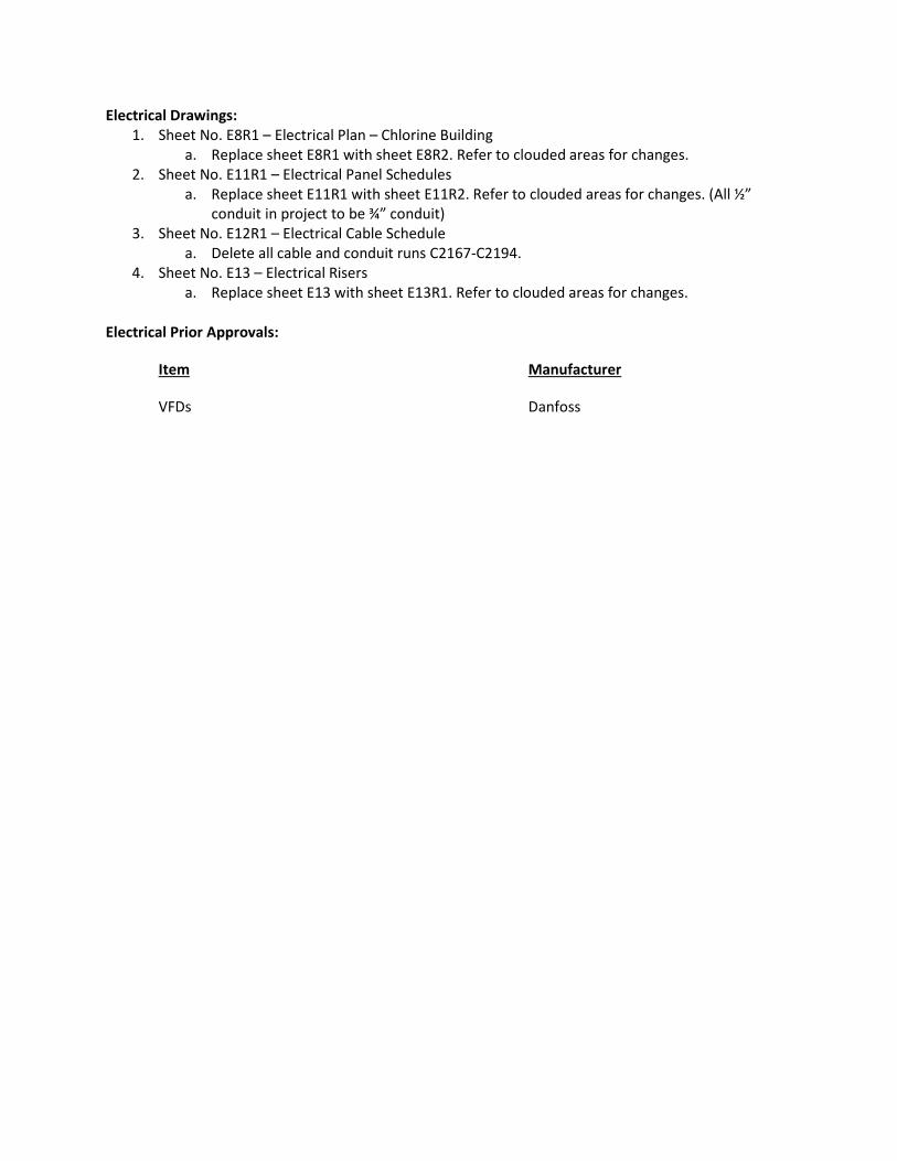
Electrical Drawings:
1. Sheet No. E8R1 – Electrical Plan – Chlorine Building
a. Replace sheet E8R1 with sheet E8R2. Refer to clouded areas for changes.
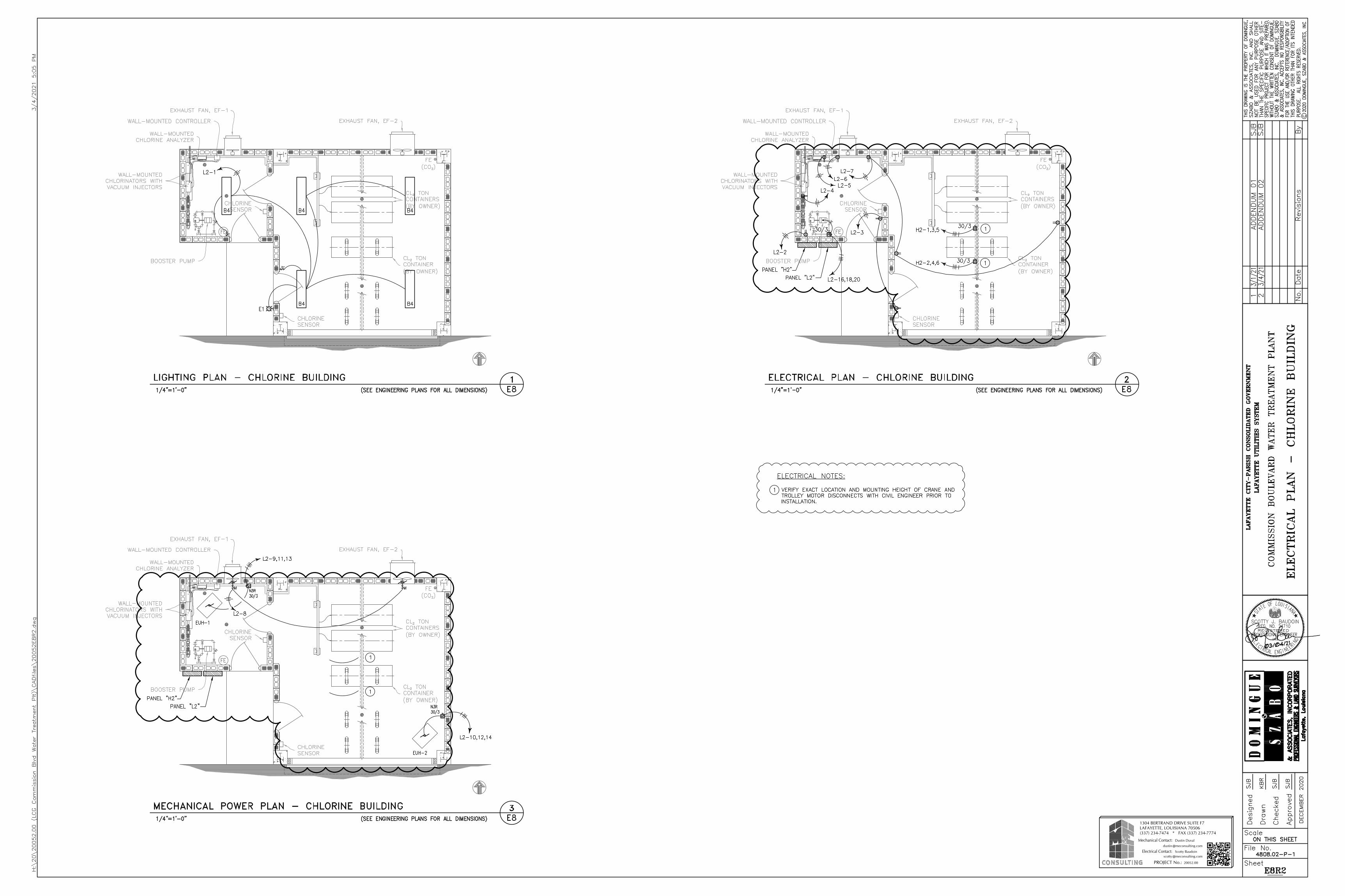
2. Sheet No. E11R1 – Electrical Panel Schedules
a. Replace sheet E11R1 with sheet E11R2. Refer to clouded areas for changes. (All ½”
conduit in project to be ¾” conduit)
3. Sheet No. E12R1 – Electrical Cable Schedule
a. Delete all cable and conduit runs C2167-C2194.
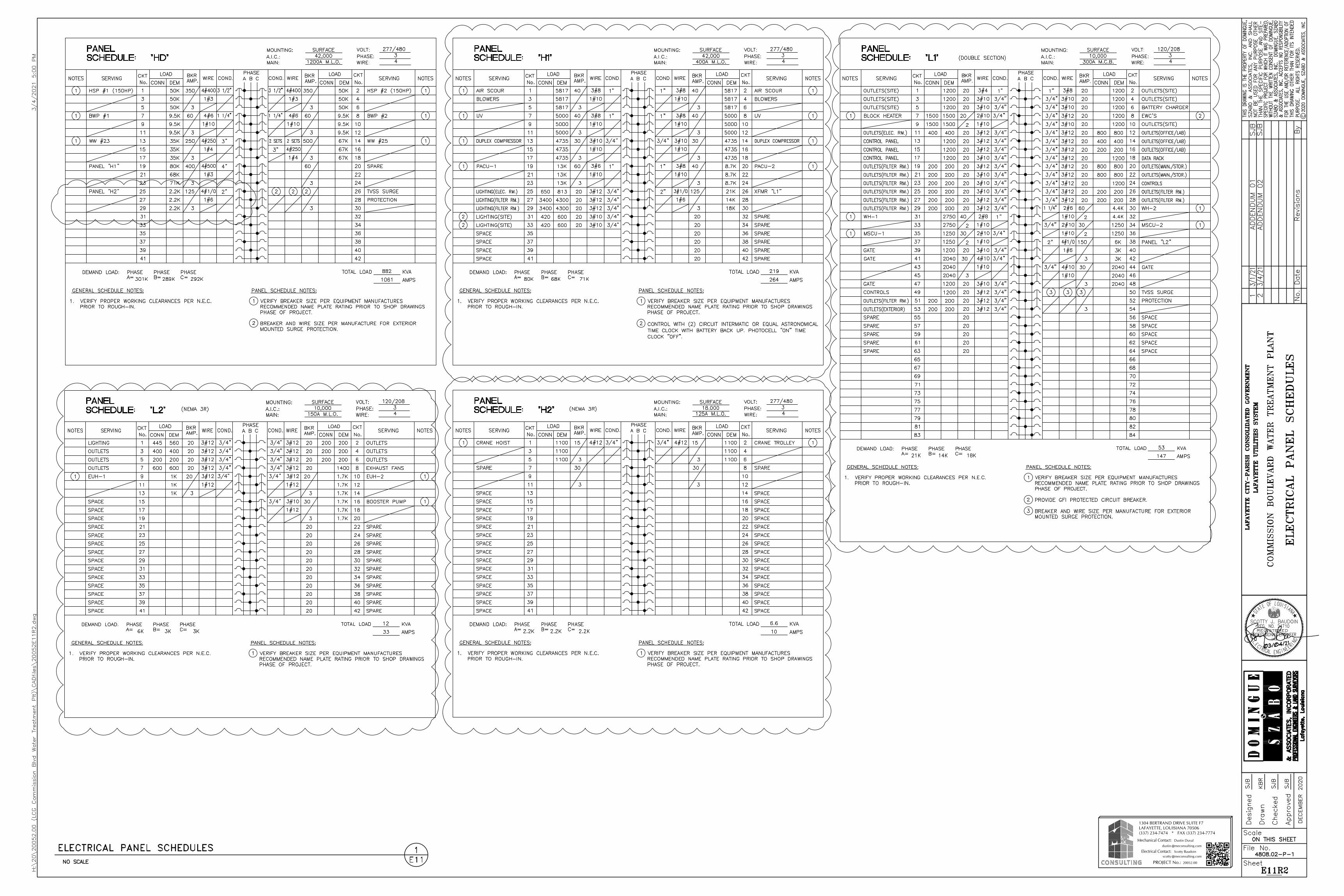
4. Sheet No. E13 – Electrical Risers
a. Replace sheet E13 with sheet E13R1. Refer to clouded areas for changes.
Electrical Prior Approvals:
Item Manufacturer
VFDs Danfoss
PROJECT No.:
1304 BERTRAND DRIVE SUITE F7LAFAYETTE, LOUISIANA 70506(337) 234-7474 * FAX (337) 234-7774
Mechanical Contact:
Electrical Contact:@meconsulting.com
@meconsulting.comScotty Baudoin
Dustin Duval
20052.00
dustin
scotty
PROJECT No.:
1304 BERTRAND DRIVE SUITE F7LAFAYETTE, LOUISIANA 70506(337) 234-7474 * FAX (337) 234-7774
Mechanical Contact:
Electrical Contact:@meconsulting.com
@meconsulting.comScotty Baudoin
Dustin Duval
20052.00
dustin
scotty
PROJECT No.:
1304 BERTRAND DRIVE SUITE F7LAFAYETTE, LOUISIANA 70506(337) 234-7474 * FAX (337) 234-7774
Mechanical Contact:
Electrical Contact:@meconsulting.com
@meconsulting.comScotty Baudoin
Dustin Duval
20052.00
dustin
scotty