Embed Size (px)
Citation preview
Summary of Martensite Formation Simulations
June 27, 2012
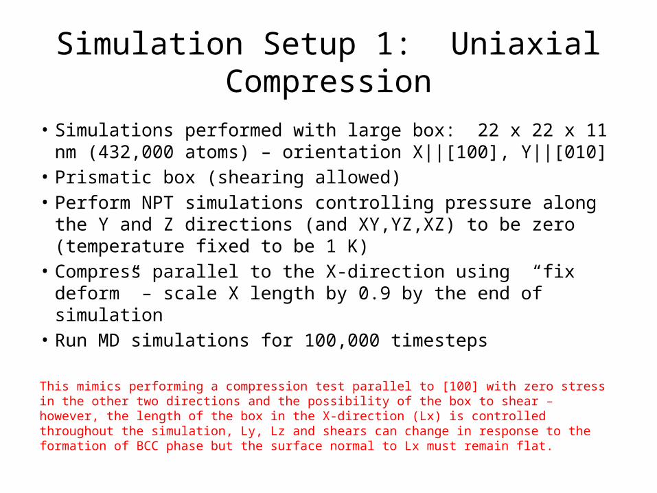
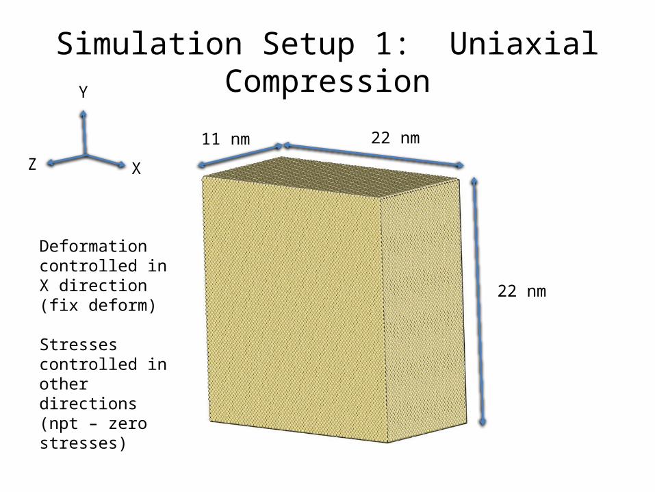
Simulation Setup 1: Uniaxial Compression
• Simulations performed with large box: 22 x 22 x 11 nm (432,000 atoms) – orientation X||[100], Y||[010]
• Prismatic box (shearing allowed)• Perform NPT simulations controlling pressure along the Y and
Z directions (and XY,YZ,XZ) to be zero (temperature fixed to be 1 K)
• Compress parallel to the X-direction using “fix deform” – scale X length by 0.9 by the end of simulation
• Run MD simulations for 100,000 timesteps
This mimics performing a compression test parallel to [100] with zero stress in the other two directions and the possibility of the box to shear – however, the length of the box in the X-direction (Lx) is controlled throughout the simulation, Ly, Lz and shears can change in response to the formation of BCC phase but the surface normal to Lx must remain flat.
Simulation Setup 1: Uniaxial Compression
X
Y
Z
22 nm
22 nm
11 nm
Deformation controlled in X direction (fix deform)
Stresses controlled in other directions (npt – zero stresses)
Results 1: Stress-Strain
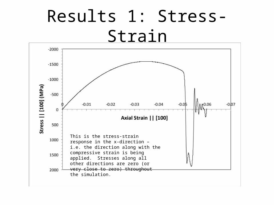
This is the stress-strain response in the x-direction – i.e. the direction along with the compressive strain is being applied. Stresses along all other directions are zero (or very close to zero) throughout the simulation.
Results 1: Stress-Strain
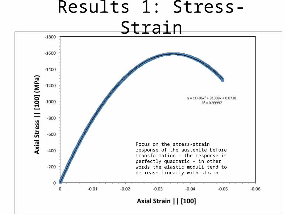
Focus on the stress-strain response of the austenite before transformation – the response is perfectly quadratic – in other words the elastic moduli tend to decrease linearly with strain
Results 1: Softening of Elastic Constants
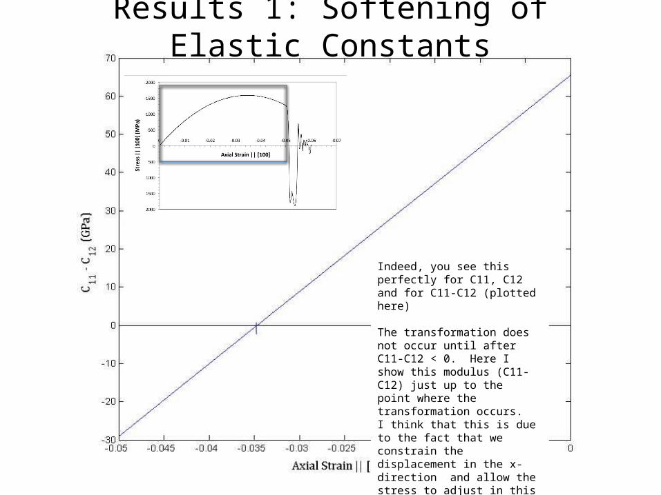
Indeed, you see this perfectly for C11, C12 and for C11-C12 (plotted here)
The transformation does not occur until after C11-C12 < 0. Here I show this modulus (C11-C12) just up to the point where the transformation occurs. I think that this is due to the fact that we constrain the displacement in the x-direction and allow the stress to adjust in this direction.
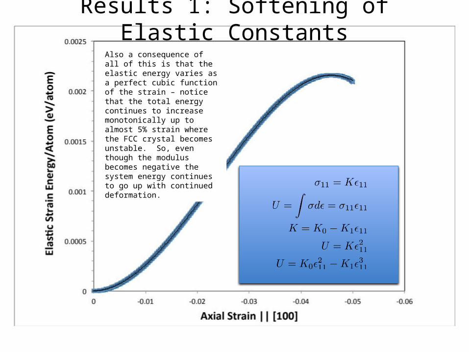
Results 1: Softening of Elastic ConstantsAlso a consequence of all of this is that the elastic energy varies as a perfect cubic function of the strain – notice that the total energy continues to increase monotonically up to almost 5% strain where the FCC crystal becomes unstable. So, even though the modulus becomes negative the system energy continues to go up with continued deformation.
Results 1: Softening of Elastic Constants
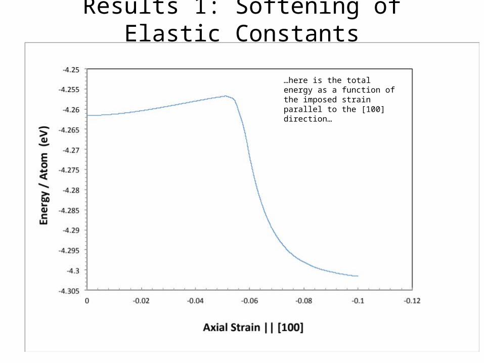
…here is the total energy as a function of the imposed strain parallel to the [100] direction…
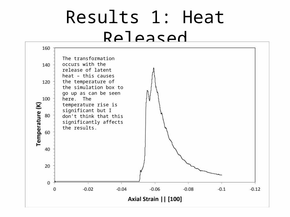
Results 1: Heat ReleasedThe transformation occurs with the release of latent heat – this causes the temperature of the simulation box to go up as can be seen here. The temperature rise is significant but I don’t think that this significantly affects the results.
Results 1: Transformation
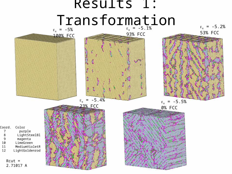
Coord. Color 7 purple 8 LightSteelBlue 9 magenta 10 LimeGreen 11 MediumVioletRed 12 LightGoldenrod
ex = -5% 100% FCC
ex = -5.1% 93% FCC
ex = -5.2% 53% FCC
ex = -5.4% 23% FCC
ex = -5.5% 0% FCC
Rcut = 2.71017 A
Results 1: Crystallography
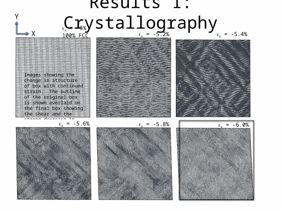
Images showing the change in structure of box with continued strain. The outline of the original box is shown overlaid on the final box showing the shear and the strong decrease in height in the y-direction
ex = -5% 100% FCC
Y
X ex = -5.2% ex = -5.4%
ex = -5.6% ex = -5.8% ex = -6.0%
Results 1: Crystallography
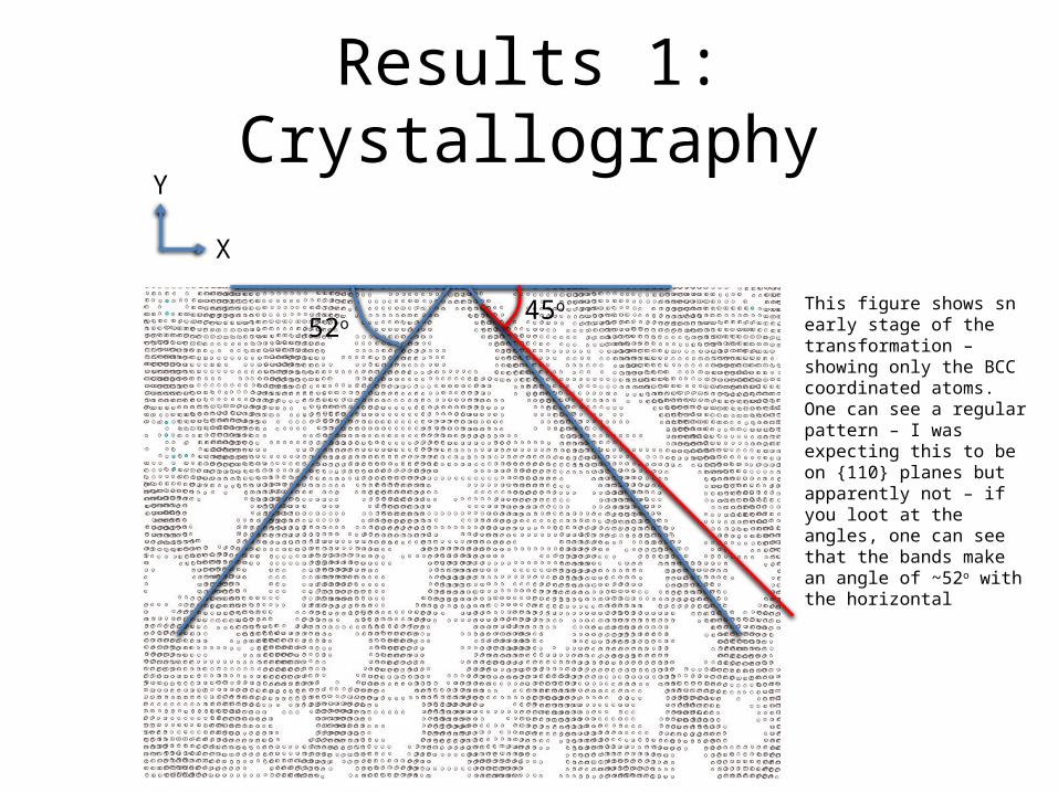
This figure shows sn early stage of the transformation – showing only the BCC coordinated atoms. One can see a regular pattern – I was expecting this to be on {110} planes but apparently not – if you loot at the angles, one can see that the bands make an angle of ~52o with the horizontal
Y
X
45o
52o
Results 1: Crystallography
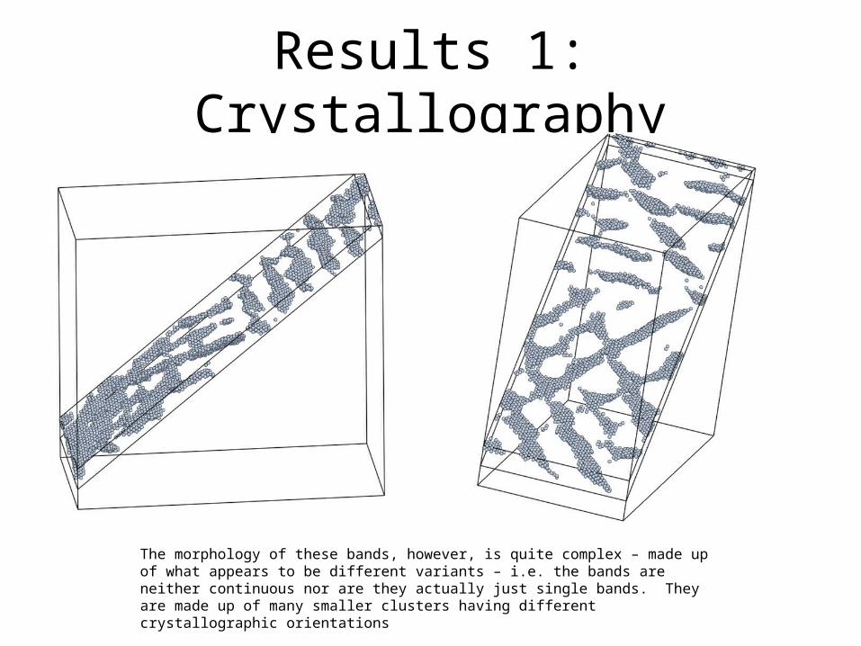
The morphology of these bands, however, is quite complex – made up of what appears to be different variants – i.e. the bands are neither continuous nor are they actually just single bands. They are made up of many smaller clusters having different crystallographic orientations
Results 1: Crystallography
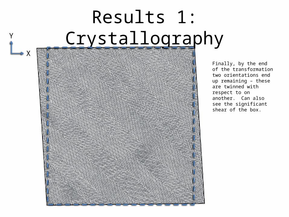
Finally, by the end of the transformation two orientations end up remaining – these are twinned with respect to on another. Can also see the significant shear of the box.
Y
X
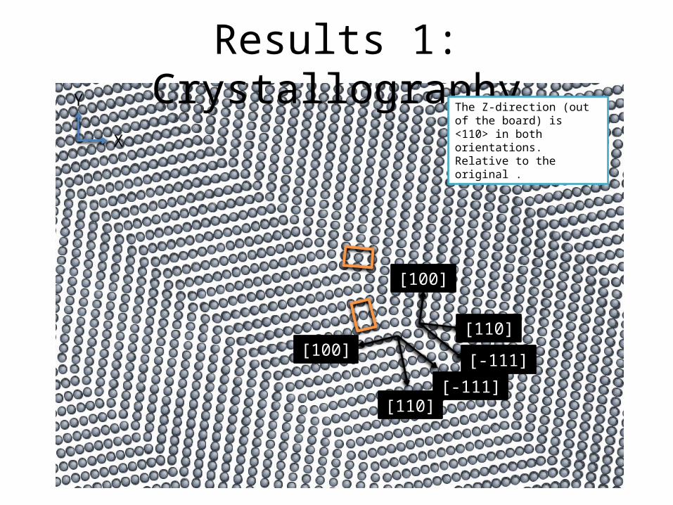
Results 1: CrystallographyThe Z-direction (out of the board) is <110> in both orientations. Relative to the original .
Y
X
[100]
[110]
[-111][100]
[110][-111]
Results 1: Crystallography
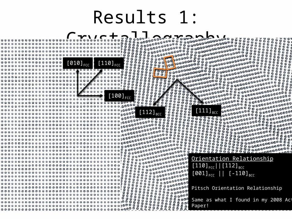
[110]FCC
[112]BCC[111]BCC
Orientation Relationship[110]FCC||[112]BCC
[001]FCC || [-110]BCC
Pitsch Orientation Relationship
Same as what I found in my 2008 ActaPaper!
[100]FCC
[010]FCC
Summary
• Get transformation at ~5% strain – once rate of energy storage starts to decrease
• Formation of many small variants (different orientations) giving away to two twinned variants
• Appears that Pitsch orientation relationship exists between original FCC and product BCC
Results 1: Crystallography
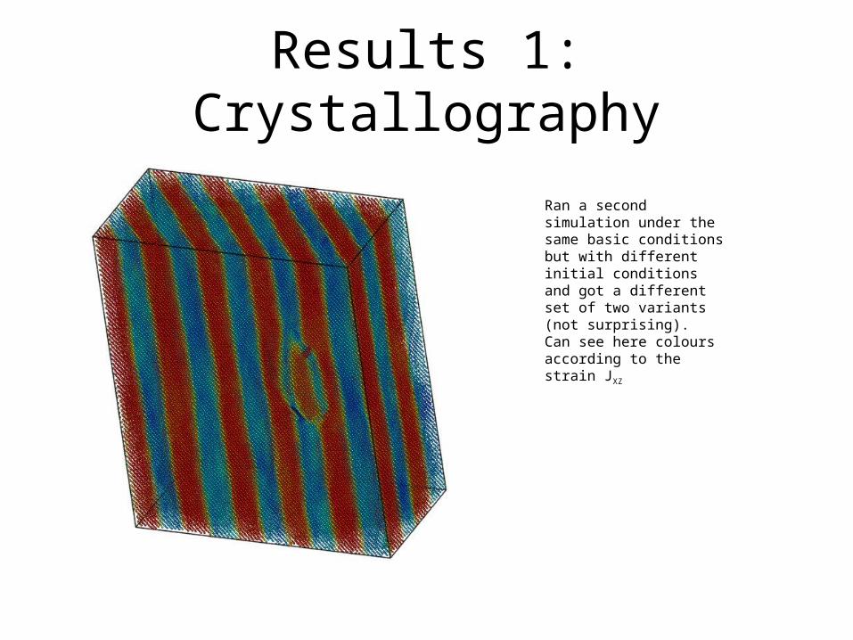
Ran a second simulation under the same basic conditions but with different initial conditions and got a different set of two variants (not surprising). Can see here colours according to the strain JXZ
Results 1: Crystallography
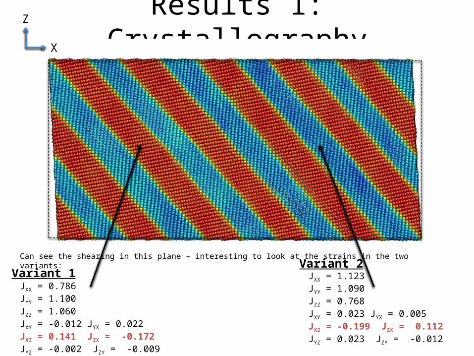
Can see the shearing in this plane – interesting to look at the strains in the two variants:
Z
X
JXX = 0.786 JYY = 1.100JZZ = 1.060JXY = -0.012 JYX = 0.022JXZ = 0.141 JZX = -0.172JYZ = -0.002 JZY = -0.009
JXX = 1.123 JYY = 1.090JZZ = 0.768JXY = 0.023 JYX = 0.005JXZ = -0.199 JZX = 0.112JYZ = 0.023 JZY = -0.012
Variant 1Variant 2
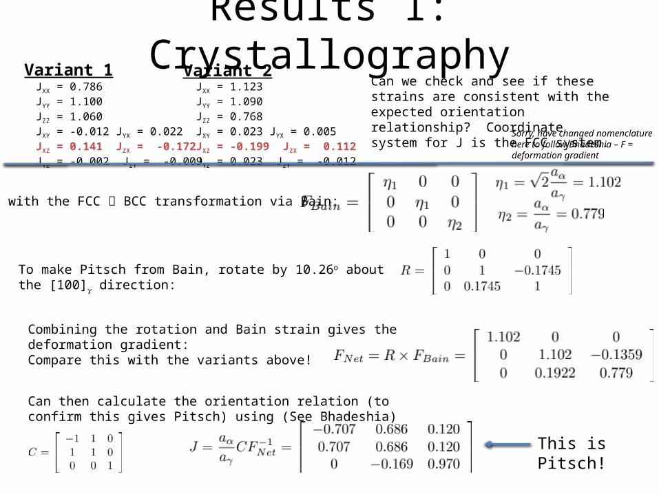
Results 1: CrystallographyCan we check and see if these strains are consistent with the expected orientation relationship? Coordinate system for J is the FCC system.
JXX = 0.786 JYY = 1.100JZZ = 1.060JXY = -0.012 JYX = 0.022JXZ = 0.141 JZX = -0.172JYZ = -0.002 JZY = -0.009
JXX = 1.123 JYY = 1.090JZZ = 0.768JXY = 0.023 JYX = 0.005JXZ = -0.199 JZX = 0.112JYZ = 0.023 JZY = -0.012
Variant 1 Variant 2
To make Pitsch from Bain, rotate by 10.26o about the [100]g direction:
Start with the FCC BCC transformation via Bain:
Combining the rotation and Bain strain gives the deformation gradient:Compare this with the variants above!
Can then calculate the orientation relation (to confirm this gives Pitsch) using (See Bhadeshia)
This is Pitsch!
Sorry, have changed nomenclature here to follow Bhadeshia – F = deformation gradient
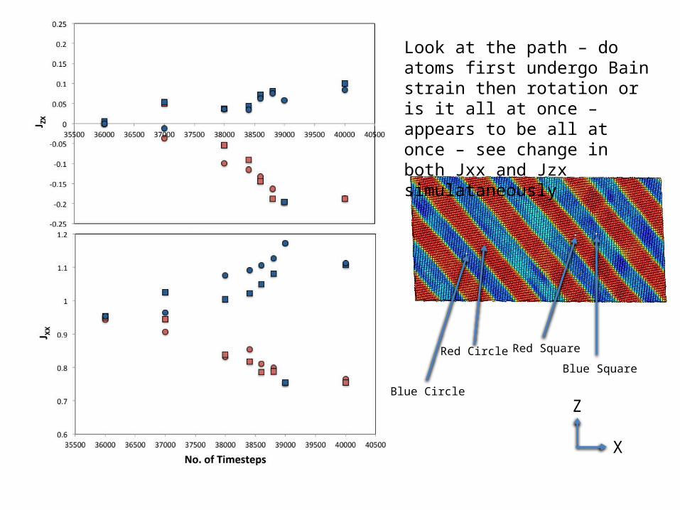
Red Circle
Blue Circle
Blue Square
Red Square
Look at the path – do atoms first undergo Bain strain then rotation or is it all at once – appears to be all at once – see change in both Jxx and Jzx simulataneously
Z
X
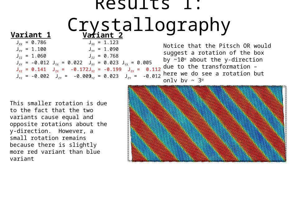
Results 1: CrystallographyNotice that the Pitsch OR would suggest a rotation of the box by ~10o about the y-direction due to the transformation – here we do see a rotation but only by ~ 3o
JXX = 0.786 JYY = 1.100JZZ = 1.060JXY = -0.012 JYX = 0.022JXZ = 0.141 JZX = -0.172JYZ = -0.002 JZY = -0.009
JXX = 1.123 JYY = 1.090JZZ = 0.768JXY = 0.023 JYX = 0.005JXZ = -0.199 JZX = 0.112JYZ = 0.023 JZY = -0.012
Variant 1 Variant 2
This smaller rotation is due to the fact that the two variants cause equal and opposite rotations about the y-direction. However, a small rotation remains because there is slightly more red variant than blue variant
Summary
• Can show that the local strains found at individual atoms are consistent with that expected from the Pitsch orientation relationship
• Seems that the transformation from FCC BCC with Pitsch OR follows a continuous path – don’t have a first Bain strain followed by rotation – both processes occur simultaneously
Simulation 2: Control Deformation Purely by Stress
• Changed the simulation to perform NPT with zero stress in all directions except the X-direction
• In the X-direction the stress was increased from 0 to – 2GPa over 100,000 time steps – previously the strain (deformation) was controlled in the X-direction and the stress was free to change in this direction
• Box size and shape and boundary conditions were the same as for the previous simulations.
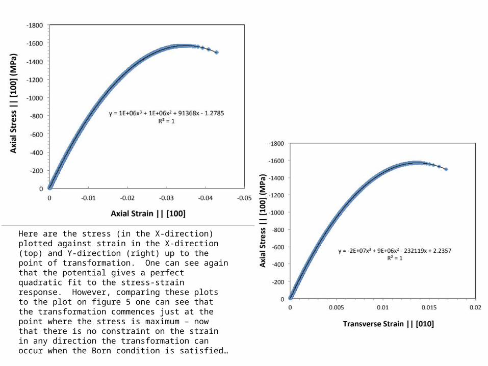
Here are the stress (in the X-direction) plotted against strain in the X-direction (top) and Y-direction (right) up to the point of transformation. One can see again that the potential gives a perfect quadratic fit to the stress-strain response. However, comparing these plots to the plot on figure 5 one can see that the transformation commences just at the point where the stress is maximum – now that there is no constraint on the strain in any direction the transformation can occur when the Born condition is satisfied…
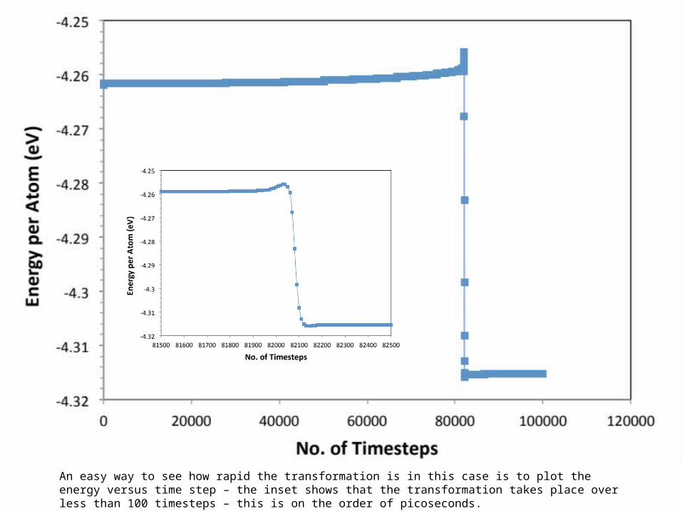
An easy way to see how rapid the transformation is in this case is to plot the energy versus time step – the inset shows that the transformation takes place over less than 100 timesteps – this is on the order of picoseconds.
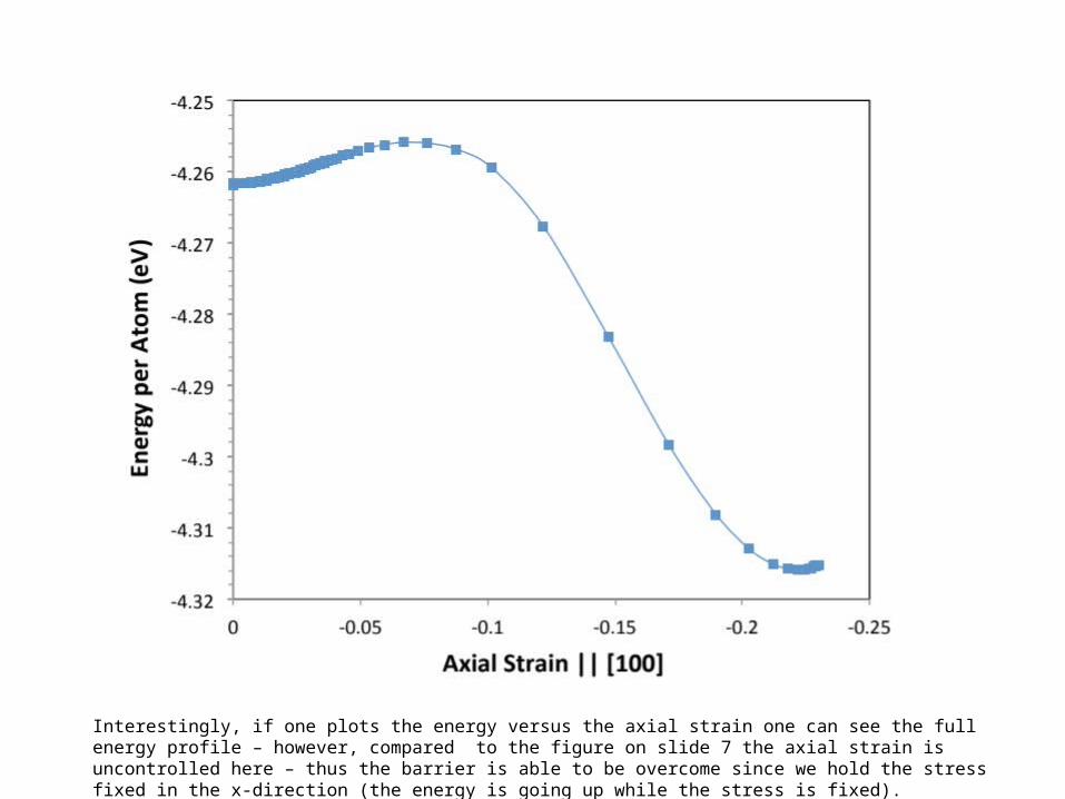
Interestingly, if one plots the energy versus the axial strain one can see the full energy profile – however, compared to the figure on slide 7 the axial strain is uncontrolled here – thus the barrier is able to be overcome since we hold the stress fixed in the x-direction (the energy is going up while the stress is fixed).
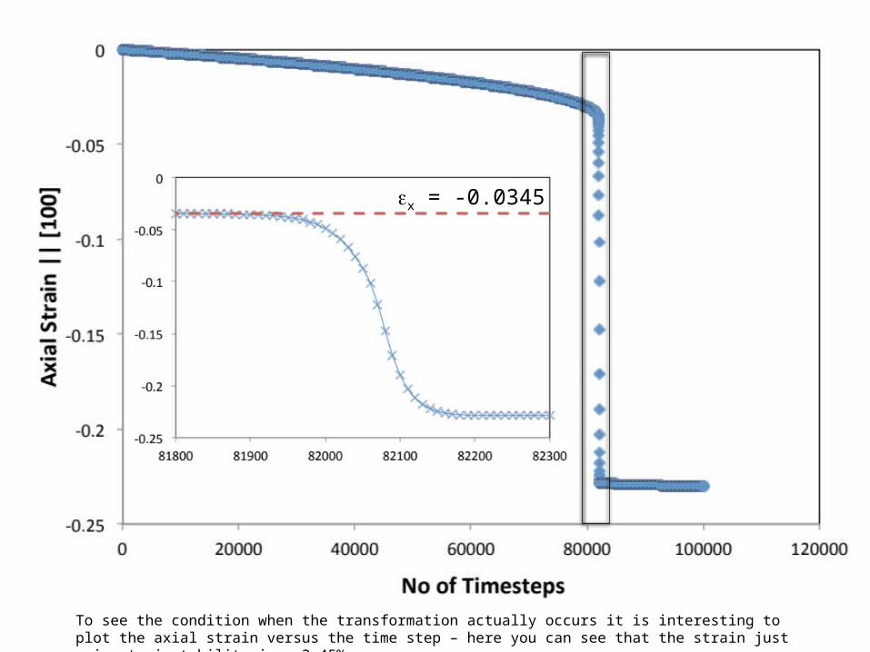
ex = -0.0345
To see the condition when the transformation actually occurs it is interesting to plot the axial strain versus the time step – here you can see that the strain just prior to instability is ~ 3.45%...
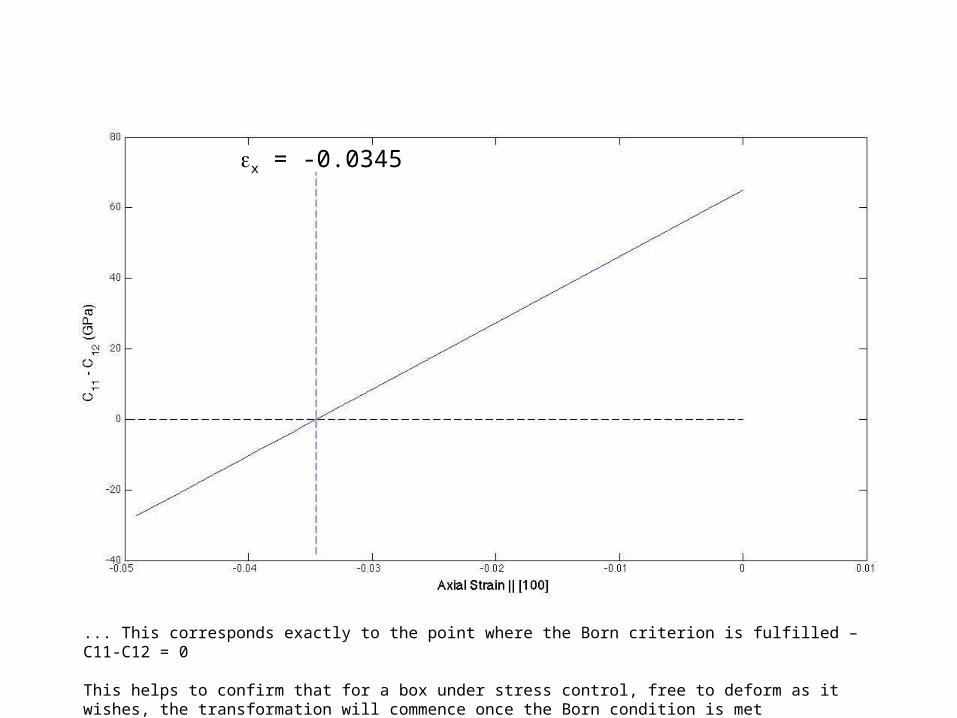
ex = -0.0345
... This corresponds exactly to the point where the Born criterion is fulfilled – C11-C12 = 0
This helps to confirm that for a box under stress control, free to deform as it wishes, the transformation will commence once the Born condition is met
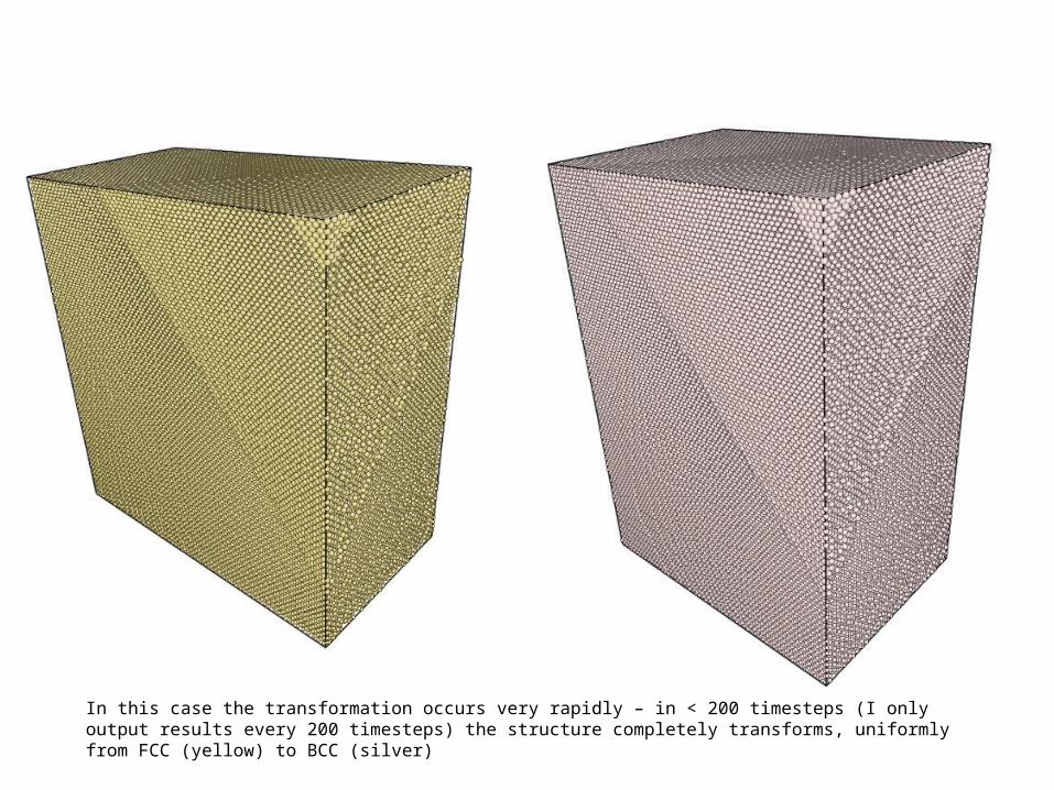
In this case the transformation occurs very rapidly – in < 200 timesteps (I only output results every 200 timesteps) the structure completely transforms, uniformly from FCC (yellow) to BCC (silver)
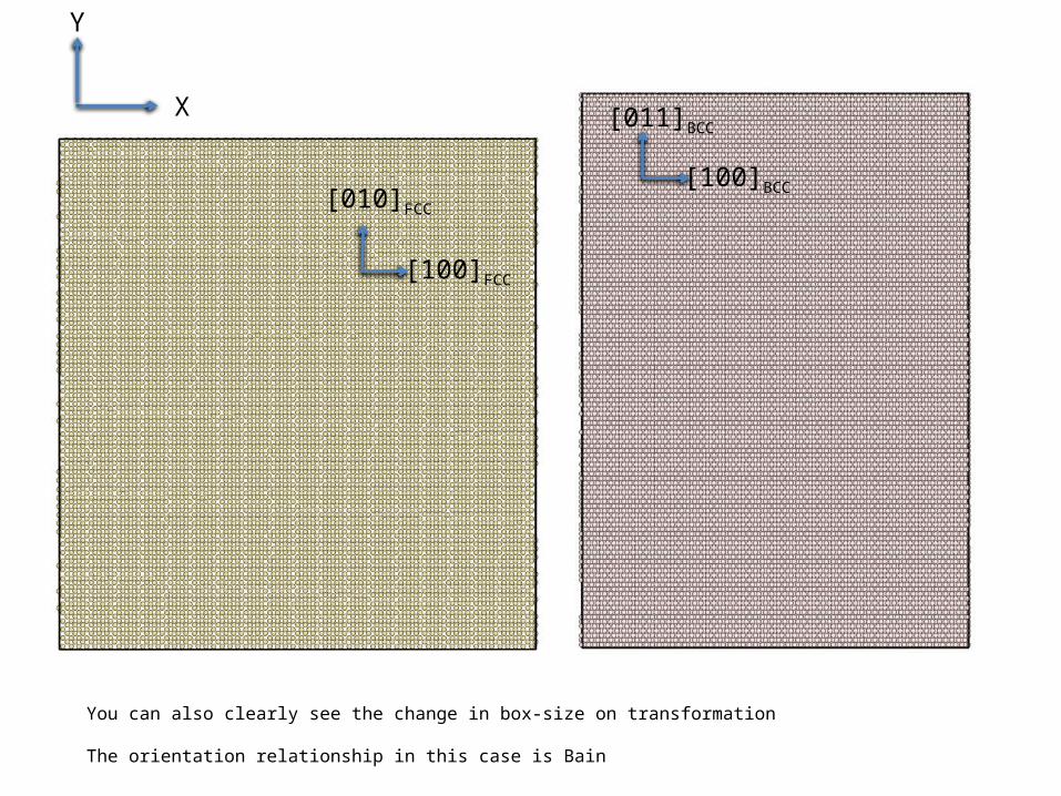
You can also clearly see the change in box-size on transformation
The orientation relationship in this case is Bain
X
Y
[100]BCC
[011]BCC
[010]FCC
[100]FCC
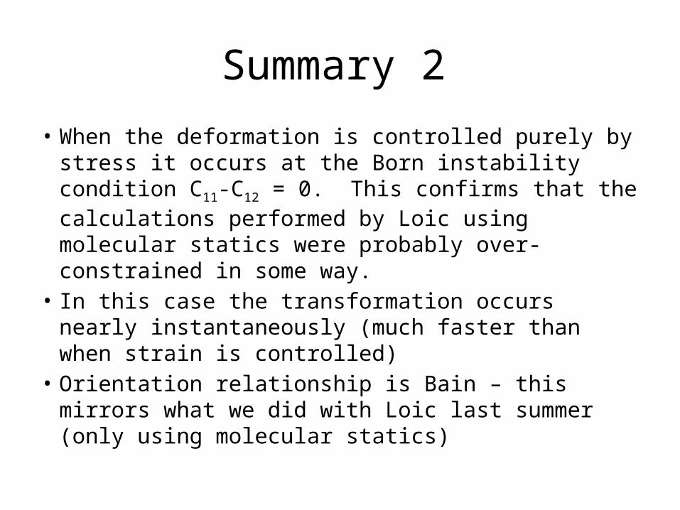
Summary 2
• When the deformation is controlled purely by stress it occurs at the Born instability condition C11-C12 = 0. This confirms that the calculations performed by Loic using molecular statics were probably over-constrained in some way.
• In this case the transformation occurs nearly instantaneously (much faster than when strain is controlled)
• Orientation relationship is Bain – this mirrors what we did with Loic last summer (only using molecular statics)


![Martensite Transformation In Sandvik Nanoflex · influence the martensite transformation [5]. Later on, the martensite fraction will be investigated that is why the martensite is](https://img.pdfslide.net/doc/110x75/5f10b9bc7e708231d44a845d/martensite-transformation-in-sandvik-influence-the-martensite-transformation-5.jpg)