Embed Size (px)
Citation preview
1
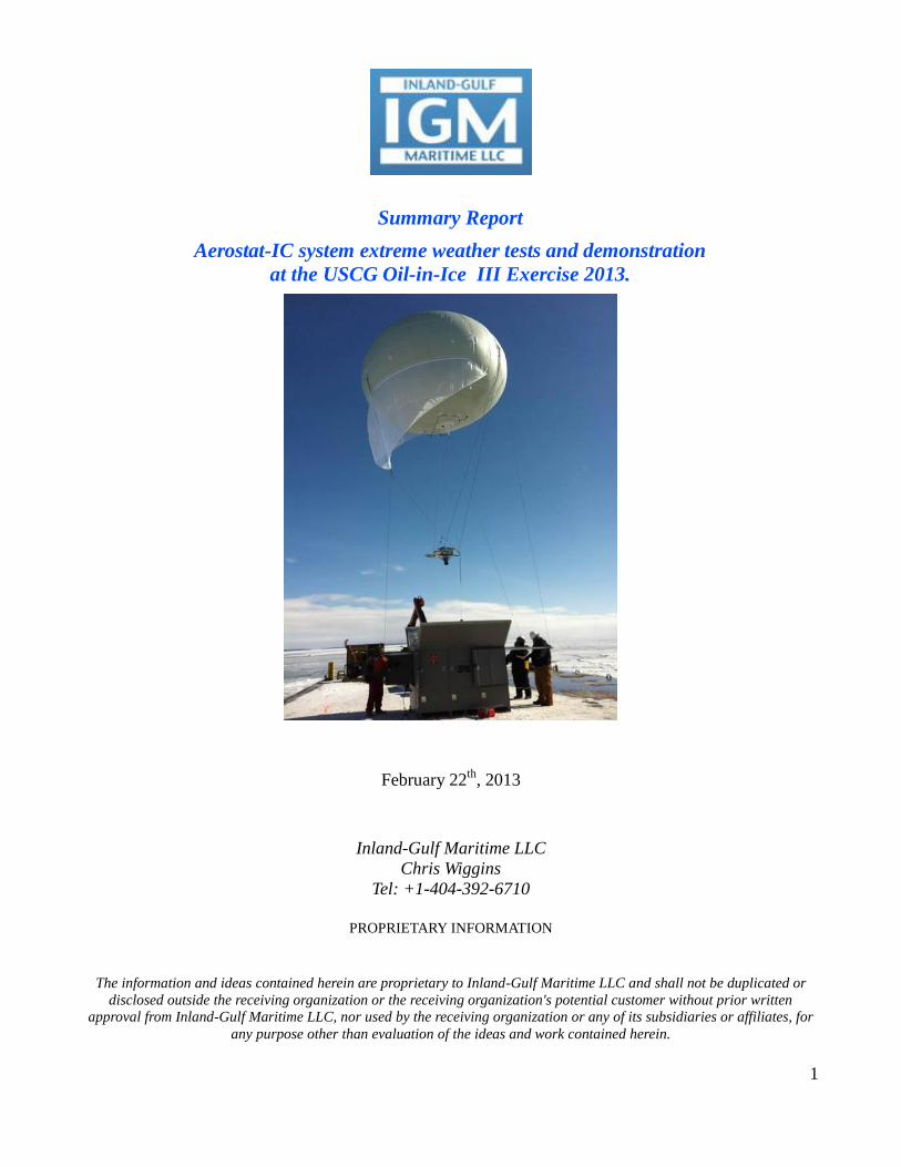
Summary Report
Aerostat-IC system extreme weather tests and demonstration
at the USCG Oil-in-Ice III Exercise 2013.
February 22th
, 2013
Inland-Gulf Maritime LLC
Chris Wiggins
Tel: +1-404-392-6710
PROPRIETARY INFORMATION
The information and ideas contained herein are proprietary to Inland-Gulf Maritime LLC and shall not be duplicated or
disclosed outside the receiving organization or the receiving organization's potential customer without prior written
approval from Inland-Gulf Maritime LLC, nor used by the receiving organization or any of its subsidiaries or affiliates, for
any purpose other than evaluation of the ideas and work contained herein.
2
ABSTRACT
Inland-Gulf Maritime, LLC participated in the USCG Oil-in-Ice III Exercise during the week of
February 18th
, 2013 held at St. Ignace, Michigan by deploying and testing the Aerostat-IC aerial
surveillance system which provided live imagery to various vessels taking part in the exercise at the
Straits of Mackinac as well as to the station located at the St. Ignace “Little Bear” Arena(ICP).
During the exercise IGM was able to test the Aerostat-IC system operation in extreme weather
conditions and learned a great deal about operating in high gusty winds and in an extreme cold weather
environment. The extent to which mechanical and thermal wind currents affect the launch and retrieval
of the aerostat confirmed that the launch and retrieval “set-up” are a key element for a successful
operation. The “lessons learned” point toward having a dedicated and free roaming vessel dedicated to
this task.
IGM also tested our newly developed and integrated Long Range Video Communication (LRVC)
technology co-developed by IGM and L3 Communications to transmit video to the on shore ICP at St.
Ignace, as well as to the USCG Cutter Hollyhock, the Icebreaker Tug Nickelena, and the Icebreaker
Tug Erika Kobasic as well as to the Aerostat-IC ground control station located on the Barge where the
Aerostat-IC platform was stationed.
Live video of USCG tactical operations including fire monitor enabled oil herding, skimming, fire
boom deployment, and man overboard and ice rescues were sent from the Aerostat-IC aerial
surveillance platform to the various vessels and the ICP. All video was also recorded by the control
station on the Barge allowing review of the operations.
3
Acknowledgment
We extend our gratitude to the following organizations for inviting Inland Gulf Maritime (IGM) to
participate in this exercise and for supporting and providing for our crew.
Prince William Sound Science Center/ Oil Spill Recovery Institute
United States Coast Guard Research and Development Center
Station St. Ignace, USCG
American Red Cross, St. Ignace, Michigan
4
Table of Contents
ABSTRACT ............................................................................................................................................... 2
Acknowledgment ....................................................................................................................................... 3 INTRODUCTION ................................................................................... Error! Bookmark not defined. BODY OF REPORT .................................................................................................................................. 7 EVALUATION ......................................................................................................................................... 14 CONCLUSIONS AND FUTURE WORK .............................................................................................. 16
5
During the year 2012, Inland-Gulf Maritime, LLC set out to develop an aerostat based aerial platform
which could carry surveillance payloads / sensors of up to 40 lbs to an altitude of at least 1000 feet, the
outcome was the Aerostat-IC platform.
The AEROSTAT-IC system is a self-contained, compact aerostat platform and payload/sensor
deployment unit which incorporates all the necessary components required to safely inflate, deploy and
operate the lighter-than-air surveillance platform. It is designed to minimize the amount of time and
resources required for the deployment and operation of the aerostat platform. This lighter-than-air
platform is able to carry a diverse number of sensors or payloads of up to 40 lbs. ranging from cameras,
communication relays, and atmospheric testing sensors among others to an altitude of up to 1000 feet.
The system utilizes a Launch and Retrieval System (LRS) which is comprised of small electrical
winches located throughout the unit and controlled by a hand held controller. The LRS is used to take
the place of additional operators during the launch and recovery phases by handling the 3 launch and
recovery lines attached to the aerostat. The system also utilizes a main tether line which anchors the
aerostat to the main base at all times and brings electrical power to the camera and down-link units and
thus eliminating the need for heavy batteries.
The aerostat (balloon) is a kite-like semi-sphere aerostat with a volume of 1400 cu.ft. and an outer shell
which protects it from the elements.
Six helium bottles of 300 cu.ft. each are housed within the unit and provide for inflation and servicing.
IGM tested the unit in fair weather conditions in the Gulf of Mexico but had yet to test its capabilities
in extreme weather conditions found in the northern parts of the US, Canada, Alaska or the Arctic.
The USCG Oil-in-Ice exercise in northern Michigan presented IGM with the opportunity to test the
system in an extreme weather environment and in real time while at the same time providing IGM the
opportunity to test newly developed video transmit and camera control technology and demonstrate its
capabilities to assist in coordinating oil spill response.
The following objectives were set by IGM during the preparation period before the USCG oil-in-Ice
exercise:
(1) Identify, modify and enhance the existing Aerostat-IC system platform with the necessary
upgrades to operate in extreme weather conditions.
(2) Integrate the Cloud Cap 200 Camera system and the newly developed RF Communications and
Video Retransmit Equipment.
6
(3) Test the newly integrated Aerostat-IC system modified for extreme weather environments in
real time and in real extreme conditions during the USCG Oil-in-Ice Demonstration Exercise.
(4) Further demonstrate the ability to safely, effectively, and efficiently deploy, and operate the
aerostat system with task specific aerial imaging and communications payloads in support of
the USCG Oil-in-Ice Demonstration Exercise.
(5) Demonstrate the ability of the RF video transmit equipment to send imagery to other vessels
and to an on-shore command center.
(6) Demonstrate the cost effectiveness of utilizing the Aerostat-IC system as an alternative aerial
surveillance platform.
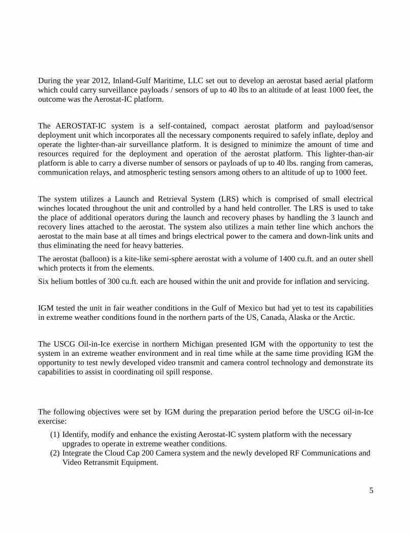
IGM participated in the USCG Oil-in-Ice III Exercise from the 18th
- 22nd
of February 2013 in St.
Ignace, Michigan. There were two days of operations where the Aerostat-IC system was to be deployed
and operated with specific tasks in support of the exercise.
7
BODY OF REPORT
Potential Improvements - Identification and Modifications to the Aerostat-IC platform
During the month of January IGM began identifying any potential improvements necessary to be made
to the Aerostat-IC platform which could help enhance its operation in extreme weather environments.
The following were identified and performed improvements to the Aerostat-IC system:
Replacement of the main tether line to a lighter weight tether line in order to counter the
potential extra weight of ice and or snow accumulation on the aerostat balloon during operation.
The original tether line weighed 4.8 lbs/100 feet. The new and lighter tether line installed
weighs 2.7 lbs/100 feet and incorporated two #20 WG to carry electrical power up to the
payload/sensor. This helped increase the net-lift of the Aerostat-IC system by 21 lbs. This
additional lift means that if snow was encountered during the operation, it would provide an
extra 21 lbs to counter the extra weight from snow accumulation on top of the aerostat.
Replacement of the Launch and Retrieval System (LRS) winches to models with higher
strength in order to increase the safety factor during potential sustained high and gusty wind
velocities.
Replacement of back-up batteries with High Cold Cranking Amps Batteries to ensure that the
back-up batteries would be able to provide enough power to the main tether winch, the LRS and
the payload in the event ground power loss. This would allow continuous operation of the
system in case of a power loss was to occur during a critical assigned task and would allow for
the safely retrieval of the payload/sensor and aerostat.
Upgrade to the Emergency Deflation Device to reduce its weight and upgrade its casing to
better protect it from extreme weather.
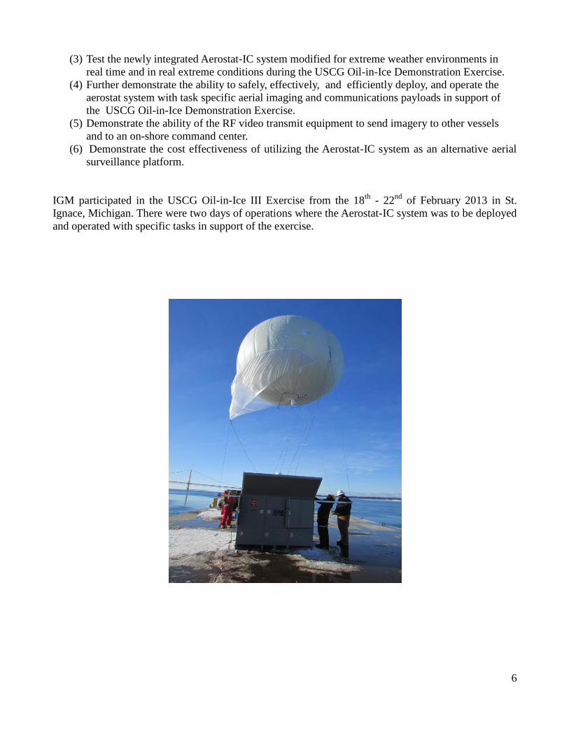
Selection and Integration of Wireless Technology for Video Transmission
IGM also researched new wireless technology to send video directly from the aerostat to the various
vessels and command center. The following equipment was selected and integrated with the aerostat
system:
RF Compact Multi-Band Data Link unit
RF Mini UAV Data Link unit
RF Soldier ISR Receiver (SIR) Tactical Rover units
RF Rover 6 Transceiver units
8
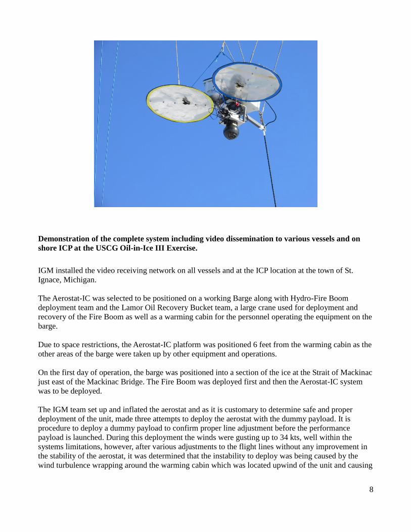
Demonstration of the complete system including video dissemination to various vessels and on
shore ICP at the USCG Oil-in-Ice III Exercise.
IGM installed the video receiving network on all vessels and at the ICP location at the town of St.
Ignace, Michigan.
The Aerostat-IC was selected to be positioned on a working Barge along with Hydro-Fire Boom
deployment team and the Lamor Oil Recovery Bucket team, a large crane used for deployment and
recovery of the Fire Boom as well as a warming cabin for the personnel operating the equipment on the
barge.
Due to space restrictions, the Aerostat-IC platform was positioned 6 feet from the warming cabin as the
other areas of the barge were taken up by other equipment and operations.
On the first day of operation, the barge was positioned into a section of the ice at the Strait of Mackinac
just east of the Mackinac Bridge. The Fire Boom was deployed first and then the Aerostat-IC system
was to be deployed.
The IGM team set up and inflated the aerostat and as it is customary to determine safe and proper
deployment of the unit, made three attempts to deploy the aerostat with the dummy payload. It is
procedure to deploy a dummy payload to confirm proper line adjustment before the performance
payload is launched. During this deployment the winds were gusting up to 34 kts, well within the
systems limitations, however, after various adjustments to the flight lines without any improvement in
the stability of the aerostat, it was determined that the instability to deploy was being caused by the
wind turbulence wrapping around the warming cabin which was located upwind of the unit and causing
9
extensive currents of disturbed eddies. It was decided to abort deploying the aerostat as a safety
measure.
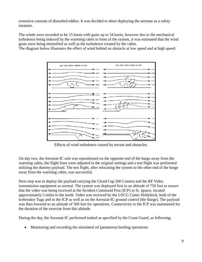
The winds were recorded to be 15 knots with gusts up to 34 knots, however due to the mechanical
turbulence being induced by the warming cabin in front of the system, it was estimated that the wind
gusts were being intensified as well as the turbulence created by the cabin.
The diagram below illustrates the effect of wind behind an obstacle at low speed and at high speed:
Effects of wind turbulence caused by terrain and obstacles.
On day two, the Aerostat-IC unit was repositioned on the opposite end of the barge away from the
warming cabin, the flight lines were adjusted to the original settings and a test flight was performed
utilizing the dummy payload. The test flight, after relocating the system to the other end of the barge
away from the warming cabin, was successful.
Next step was to deploy the payload carrying the Cloud Cap 200 Camera and the RF Video
transmission equipment as normal. The system was deployed first to an altitude of 750 feet to ensure
that the video was being received at the Incident Command Post (ICP) in St. Ignace, located
approximately 5 miles to the north. Video was received by the USCG Cutter Hollyhock, both of the
Icebreaker Tugs and in the ICP as well as on the Aerostat-IC ground control (the Barge). The payload
was then lowered to an altitude of 500 feet for operations. Connectivity to the ICP was maintained for
the duration of the exercise from this altitude.
During the day, the Aerostat-IC performed tasked as specified by the Coast Guard, as following;
Monitoring and recording the simulated oil (peatmoss) herding operations
10
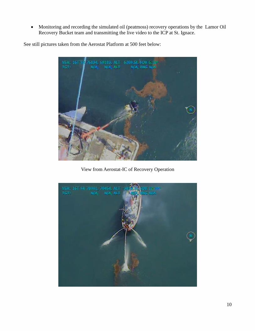
Monitoring and recording the simulated oil (peatmoss) recovery operations by the Lamor Oil
Recovery Bucket team and transmitting the live video to the ICP at St. Ignace.
See still pictures taken from the Aerostat Platform at 500 feet below:
View from Aerostat-IC of Recovery Operation
11
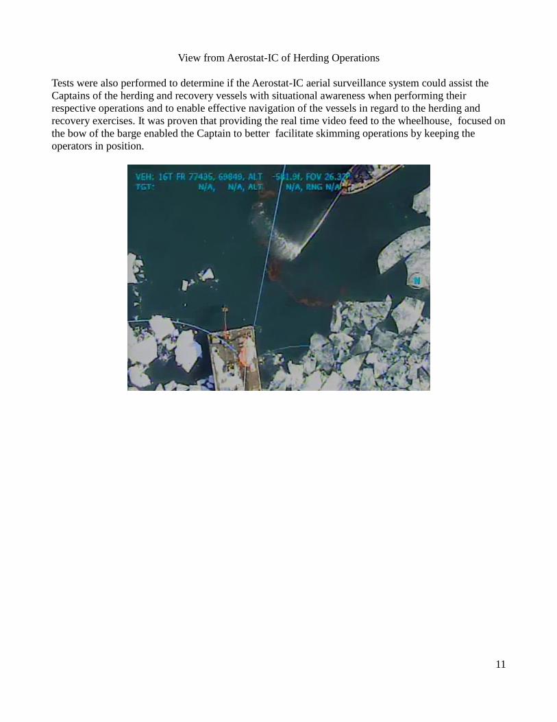
View from Aerostat-IC of Herding Operations
Tests were also performed to determine if the Aerostat-IC aerial surveillance system could assist the
Captains of the herding and recovery vessels with situational awareness when performing their
respective operations and to enable effective navigation of the vessels in regard to the herding and
recovery exercises. It was proven that providing the real time video feed to the wheelhouse, focused on
the bow of the barge enabled the Captain to better facilitate skimming operations by keeping the
operators in position.
12
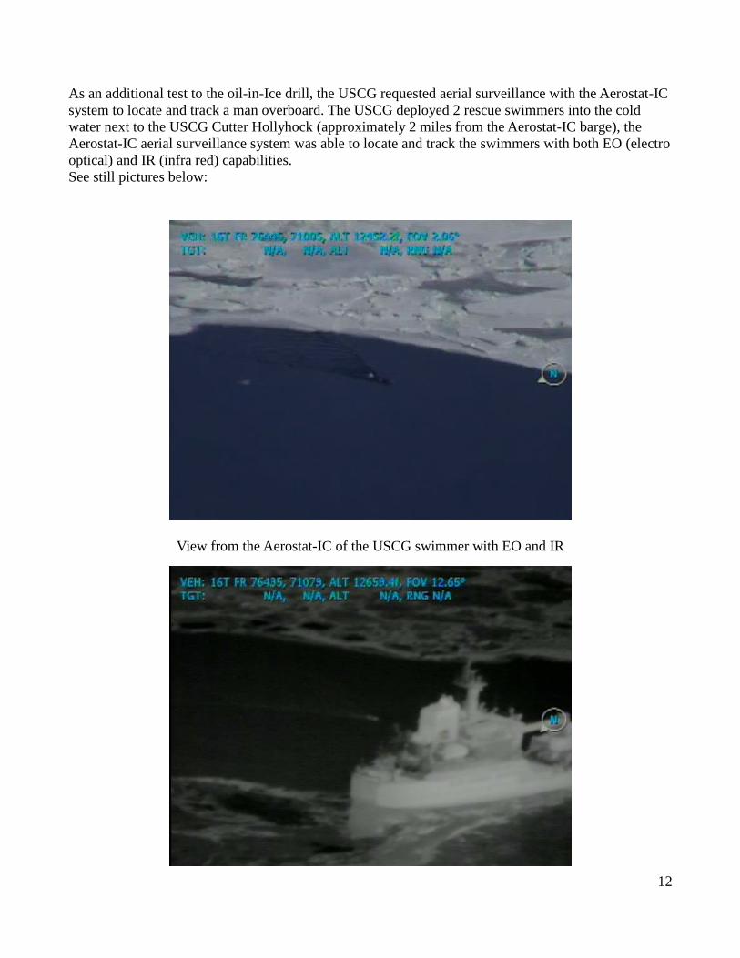
As an additional test to the oil-in-Ice drill, the USCG requested aerial surveillance with the Aerostat-IC
system to locate and track a man overboard. The USCG deployed 2 rescue swimmers into the cold
water next to the USCG Cutter Hollyhock (approximately 2 miles from the Aerostat-IC barge), the
Aerostat-IC aerial surveillance system was able to locate and track the swimmers with both EO (electro
optical) and IR (infra red) capabilities.
See still pictures below:
View from the Aerostat-IC of the USCG swimmer with EO and IR
13
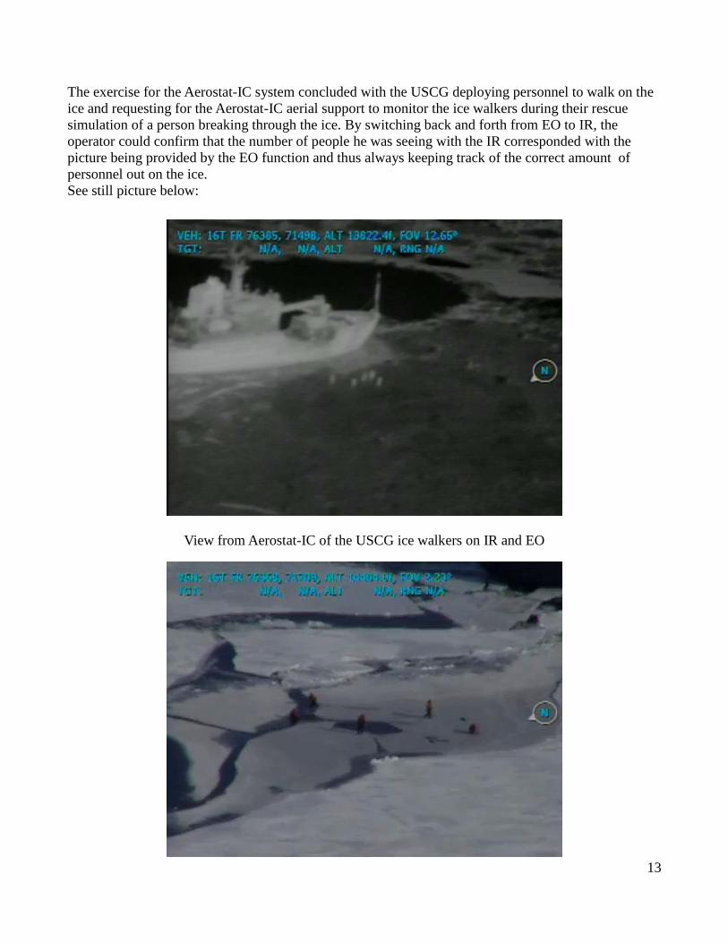
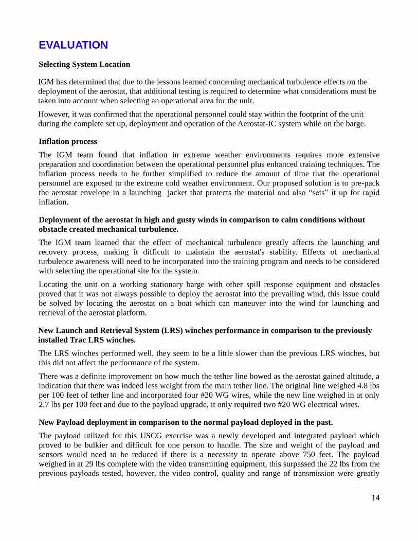
The exercise for the Aerostat-IC system concluded with the USCG deploying personnel to walk on the
ice and requesting for the Aerostat-IC aerial support to monitor the ice walkers during their rescue
simulation of a person breaking through the ice. By switching back and forth from EO to IR, the
operator could confirm that the number of people he was seeing with the IR corresponded with the
picture being provided by the EO function and thus always keeping track of the correct amount of
personnel out on the ice.
See still picture below:
View from Aerostat-IC of the USCG ice walkers on IR and EO
14
EVALUATION
Selecting System Location
IGM has determined that due to the lessons learned concerning mechanical turbulence effects on the
deployment of the aerostat, that additional testing is required to determine what considerations must be
taken into account when selecting an operational area for the unit.
However, it was confirmed that the operational personnel could stay within the footprint of the unit
during the complete set up, deployment and operation of the Aerostat-IC system while on the barge.
Inflation process
The IGM team found that inflation in extreme weather environments requires more extensive
preparation and coordination between the operational personnel plus enhanced training techniques. The
inflation process needs to be further simplified to reduce the amount of time that the operational
personnel are exposed to the extreme cold weather environment. Our proposed solution is to pre-pack
the aerostat envelope in a launching jacket that protects the material and also “sets” it up for rapid
inflation.
Deployment of the aerostat in high and gusty winds in comparison to calm conditions without
obstacle created mechanical turbulence.
The IGM team learned that the effect of mechanical turbulence greatly affects the launching and
recovery process, making it difficult to maintain the aerostat's stability. Effects of mechanical
turbulence awareness will need to be incorporated into the training program and needs to be considered
with selecting the operational site for the system.
Locating the unit on a working stationary barge with other spill response equipment and obstacles
proved that it was not always possible to deploy the aerostat into the prevailing wind, this issue could
be solved by locating the aerostat on a boat which can maneuver into the wind for launching and
retrieval of the aerostat platform.
New Launch and Retrieval System (LRS) winches performance in comparison to the previously
installed Trac LRS winches.
The LRS winches performed well, they seem to be a little slower than the previous LRS winches, but
this did not affect the performance of the system.
There was a definite improvement on how much the tether line bowed as the aerostat gained altitude, a
indication that there was indeed less weight from the main tether line. The original line weighed 4.8 lbs
per 100 feet of tether line and incorporated four #20 WG wires, while the new line weighed in at only
2.7 lbs per 100 feet and due to the payload upgrade, it only required two #20 WG electrical wires.
New Payload deployment in comparison to the normal payload deployed in the past.
The payload utilized for this USCG exercise was a newly developed and integrated payload which
proved to be bulkier and difficult for one person to handle. The size and weight of the payload and
sensors would need to be reduced if there is a necessity to operate above 750 feet. The payload
weighed in at 29 lbs complete with the video transmitting equipment, this surpassed the 22 lbs from the
previous payloads tested, however, the video control, quality and range of transmission were greatly
15
improved.
Down-linking of video to the control computer at the Barge.
Control and command of the camera as well as video worked well, GPS signal was not received, this
was determined to be a hardware problem.
Down-linking of video to the USCG Cutter Hollyhock.
Video was received with good quality and at a distance of approximately 2 miles from the Aerostat-IC
payload. Maximum range of video transmission utilizing the normal vessel receivers was not tested at
this time.
Down-linking of video to the on-shore command center.
Although the ICP was located behind a small hill in the town of St. Ignace, at 500 feet of altitude the
Aerostat-IC was able to transmit and the ICP was able to receive the video real time. The ICP was
located 5 miles from the Aerostat-IC aerial system. Maximum range of the video transmission to the on
shore ICP was not tested.
Camera control utilizing Radio Frequency (Wireless) Technology
The camera was able to be fully controlled with no delay utilizing the Radio Frequency (wireless)
communication equipment.
Ability of the Aerostat-IC system to locate and track man overboard in icy conditions using EO
and IR technology.
The Aerostat-IC camera was able to locate and track the coast guard swimmer with both EO and IR
capabilities.
Ability of the Aerostat-IC system to locate, track and monitor ice walkers with EO and IR
technology.
The Aerostat-IC camera was able to locate and track the coast guard ice walkers with both EO and IR
capabilities, switching between EO and IR permitted the camera operator to confirm that the number of
people on the ice being shown on the normal video was indeed the same using the IR function and thus
being able to keep an accurate head count throughout the exercise.
16
CONCLUSIONS AND FUTURE WORK
Conclusions
Many lessons were learned during this project and several ideas for enhancing the performance and
efficiency of the system also surfaced thanks to the ability to test the system in a real extreme weather
environment. One of the main lessons learned during the course of this project was the immense effect
which mechanical turbulence can have on the stability of the aerostat during the launch and retrieval
periods.
Other important lessons learned include:
The fact that operations for inflation, launch and retrieval of the Aerostat-IC system in extreme
weather conditions require more time, coordination and efforts on behalf of the operators.
With the newly integrated technology it was possible to send video directly from the Aerostat
payload to various vessels within a 5 mile radius of the working aerial platform and to the
command center on shore as long as line of site with the receiver can be maintained.
Video provided by the Aerostat-IC system can be utilized by the captains to enhance their
situational awareness and to maneuver herding and recovery vessels during operations.
IR as well as EO capabilities of the Aerostat-IC system can be utilized to locate, track and
monitor man overboard or to assist in ice rescue operations.
The Aerostat-IC system was able to provide the required aerial coverage of the events of the
USCG Oil-in-Ice III exercise and perform the specified tasks at a fraction of the cost of
traditional air support and thus also reducing the human risks associated with traditional aerial
coverage in extreme weather environments.
It is important to establish a chain of command on who would mainly be directing what and
where, when it comes to providing the aerial coverage. The camera operator has to be focused
on the task at hand and not with conflicting instructions as to where to point the camera for
viewing during the exercise.
The final lesson learned was the realization that if dealing with a wide spread spill/response
where working vessels are a wide distance apart, it may be beneficial to mount the Aerostat-IC
on an independent vessel which can be relocated to assist where and when needed at different
working parts or operations for the oil response / recovery and or search and rescue working out
of the range of the camera system.
Future Work
With the lessons learned during the USCG Oil-in-Ice III Exercise, several a new ideas for enhanced and
improved performance of the Aerostat-IC aerial surveillance system have been discovered and IGM
will begin exploring a new approach in order to improve the system, having it work more efficiently
17
and improve performance in extreme weather environments and to meet a wider range of customers'
needs.
IGM believes that the system performance can be greatly improved with the capability to transmit the
video to a range of over 75 miles. This would entail re-designing the aerostat fabric (balloon) to act as a
parabolic base for the transmitting antennas. Incorporating this into the aerostat fabric may prove to be
the solution to extending the range while at the same time keeping the size and weight of the
sensor/payload to a minimum.
One of the challenges to be able to transmit video over a long distance is that the receiving unit and the
transmitting unit must have line of sight. Line of sight can be improved by increasing the altitude at
which the aerostat operates, however, the higher it operates, better quality camera and zoom
capabilities are required. IGM will continue exploring various types of gimbals in order to find a good
balance between higher altitude, payload weight and quality of the video.
Another improvement which IGM will explore is the ability for multiple video feeds to be received by
the on-shore command center simultaneously and thus improving the flow of information received
which will assist the command center personnel in higher quality and quicker decision making.
The system can also benefit by the ability to control the payload/sensor from multiple vessels by
creating a virtual switch which can allow not only for the interested parties to have control of the
camera during a specific task, but also to create a redundancy or back up in case that the main
sensor/payload command computer or system fails.
Along with aerostat material tests, IGM would like to perform material strength tests and material
brittleness in even colder environments.
IGM will also continue to work on the redesign of the Aerostat base platform to reduce its footprint, the
way it is secured to the vessel thus eliminating trip hazards, the aerostat inflation chamber and
enhancement of the LRS system to prevent the handling line clips from catching or tangling.
Perform research and development of a new type of aerostat balloon which would improve on the
accumulation of snow on top and thus improving its operational efficiency.
Test the unit in real time to further understand the limitations and effects of mechanical turbulence.