Embed Size (px)
Citation preview
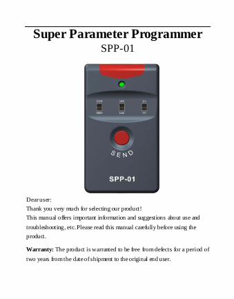
Super Parameter Programmer SPP-01
Dear user:
Thank you very much for selecting our product!
This manual offers important information and suggestions about use and
troubleshooting, etc. Please read this manual carefully before using the
product.
Warranty: The product is warranted to be free from defects for a period of
two years from the date of shipment to the original end user.
Contents
1 Important Safety Information ................................ ............ 1
2 General Information ........................................................ 1
2.1 Product Characteristic ................................ ................... 1
2.2 Main Functions ................................ ............................ 2
2.3 Recommendation ................................ ......................... 2
3 Features ................................ ................................ ........ 3
3.1 Features................................................................ ...... 3
3.2 Power Supply and Startup ................................ .............. 5
4 Software Operation ................................ ......................... 7
4.1 Software Operating Environment..................................... 7
4.2 Software Installation and Uninstalling .............................. 7
4.3 Software Operating Instructions ................................ ...... 7
5 Specification ................................ ................................ 22
5.1 Hardware Configuration .............................................. 22
5.2 SPP-01 Parameter................................ ....................... 22
6 SPP-01 Overall Dimension ................................ ............. 23
1
1 Important Safety Information
This manual contains important safety, setting and operating instructions for
SPP-01. Save these instructions.
Please inspect the product thoroughly after it is delivered. If any damage
is seen, please notify the shipping company or our company
immediately.
Read of the instructions and cautions in the manual before using.
Keep the product away from rain, exposure, severe dust, vibrations,
corrosive gas and intense electromagnetic interference.
Do not allow water to enter the controller.
Do not disassemble or attempt to repair it.
2 General Information
2.1 Product Characteristic
Super parameter programmer (SPP-01) is the simple, efficient and practical
accessory for parameter configuration with the easy one button operation.
Due to the new standard communication protocol , it applies to stand-alone
or multi-parallel products. The features of the SPP -01 are listed below.
One button and one indication led are designed for simplicity and
easy-to-operate.
RS232 (TTL), RS485 and USB communication are supported.
SPPPCTools PC software is used to configure and backup parameters
2
visually, rapidly and conveniently.
Dual power supply design. SPP -01 can be powered by battery or
Micro-USB cable applying for various environments.
2.2 Main Functions
Parameter configuration function
Load the parameter configuration to the SPP-01 via SPPPCTools PC
software and then update the device’s parameters through SPP-01 with
easy one button.
Data transparent transmission function.
SPP-01 can be used as the communication converter to connect the
device and Solar Station Monitor, a PC software, to establish remote
monitoring.
2.3 Recommendation
DCCPxxxxDP (R), LSxxxxB (PL), VSxxxxB, TracerxxxxB (PL) and
iTracerxxB series products are supported to update the configuration by
SPP-01. P lease confirm whether to support before purchasing.
3
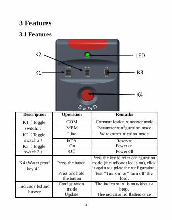
3 Features
3.1 Features
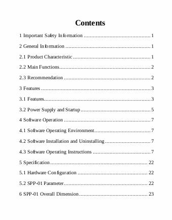
Description Operation Remarks
K1(Toggle
switch1)
COM Communication converter mode
MEM Parameter configuration mode
K2(Toggle
switch 2)
Line Wire communication mode
IrDA Reserved
K3(Toggle
switch 3)
On Power on
Off Power off
K4(Water proof
key 4)
P ress the button Press the key to enter configuration mode (the indicator led is on), click it again to update the configuration.
Press and hold the button
Test “Turn on” or “Turn off” the load.
Indicator led and buzzer
Configuration mode
The indicator led is on without a beep.
Update The indicator led flashes once
K1
K2
K3
LED
K4
4
successfully. with one short beep.
Communication error
The indicator led flashes twice with two short beeps.
The model is not matched or the
irrational configuration
The indicator led flashes triple with three short beeps.
Test The indicator light flashes for
several times with one long beep.
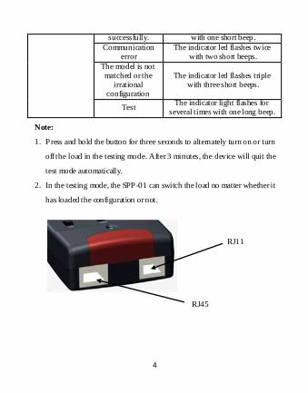
Note:
1. Press and hold the button for three seconds to alternately turn on or turn
off the load in the testing mode. After 3 minutes, the device will quit the
test mode automatically.
2. In the testing mode, the SPP -01 can switch the load no matter whether it
has loaded the configuration or not.
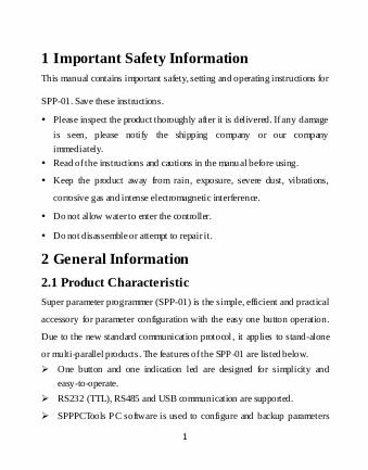
RJ11
RJ45
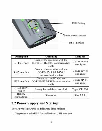
5
Description Operating Remarks
RJ11 interface Connect the controller with the
CC-TTL-TTL-150U communication cable
Update device configure
RJ45 interface Connect the controller with the
CC-RS485- RS485-150U communication cable
Update device configure
USB interface Connect to the PC with the
CC-USB-USB-150U communication cable
Update SPP01 configure
RTC battery holder
Battery for real-time time clock Type: CR1220
Battery compartment
3 batteries Size AAA
3.2 Power Supply and Startup
The SPP-01 is powered by following three methods:
1. Get power via the USB data cable from USB interface.
RTC Battery
Battery compartment
USB interface
6
2. Get power via exclusive data cable from the device.
3. Get power from 3 batteries (size AAA).
Starting SPP-01: The SPP-01 is powered on by toggling K3 switch to “ON”
Operating status Phenomena
Normal startup The green light flashes once with one beep.
No data available in
SPP-01
The green light flashes for several times with
several beeps.
7
4 Software Operation
4.1 Software Operating Environment
Hardware Environment
A Pentium 4-compatible PC
At least 512Mbyte of RAM and 55Mbyte of free disk space
Software Operating Environment
The recommended operating system is as follows:
Windows XP (32bit), Win7 (32bit/64bit), Win8 (32bit/64bit)
Installing component: Windows Installer3_1, DotNetFX40.
4.2 Software Installation and Uninstalling
Installing the software
Open directory “ SPPPCSoftwareV3.77”, and double click “setup.exe”,
after the computer start carry on the software gearing.
Uninstalling the software
Click the Start >Control Panel >Add or delete programs> SPP> Delete.
4.3 Software Operating Instructions
Get serial port number for SPP-01
1. Connect the device: Connect SPP-01 to the PC with the Micro-USB
cable and turn K3 switch to “ON” position. The SPP-01 starts normally
with indicator led flashing once and a short beep.
8
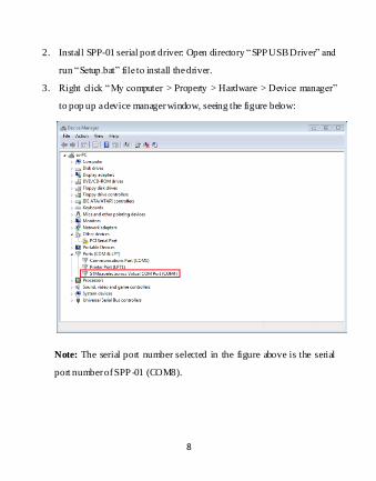
2. Install SPP-01 serial port driver: Open directory “SPP USB Driver” and
run “Setup.bat” file to install the driver.
3. Right click “My computer > Property > Hardware > Device manager”
to pop up a device manager window, seeing the figure below:
Note: The serial port number selected in the figure above is the serial
port number of SPP -01 (COM8).
9
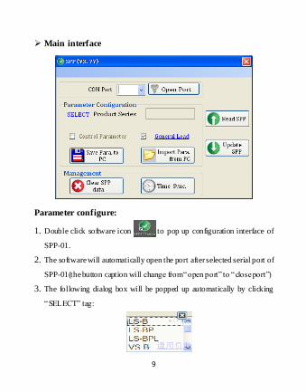
Main interface
Parameter configure:
1. Double click software icon to pop up configuration interface of
SPP-01.
2. The software will automatically open the port after selected serial port of
SPP-01(the button caption will change from “open port” to “close port”)
3. The following dialog box will be popped up automatically by clicking
“SELECT” tag:
10
Double click to select device (the configuration content will be changed
automatically).
4. Configure relevant parameters by clicking “Control Parameters”,
“General Load”, “LED Load” in the frame of Parameter Configuration
and “Time Sync” in the Management. After configuring parameters,
click “OK” to quit and return to main interface (For the parameters
without configuration, uncheck the box “ ”).
5. After configuration, click button to load configuration
into SPP-01 device (a corresponding dialog box will be popped up to
prompt whether loaded successfully or not).
Reading parameter data
If the configuration has been loaded to the SPP-0, click
button to upload the configuration in SPP -01 to PC, and refresh the
corresponding parameter configuration in “Parameter configuration”
frame, such as Control Parameter, General Load or LED Load, Time
Sync so as to view and modify the parameters.
Data clearing
If it is required to clear configuration in SPP-01, click
button directly.
Importing and exporting parameter configuration
If it is required to backup parameter configuration, click
11
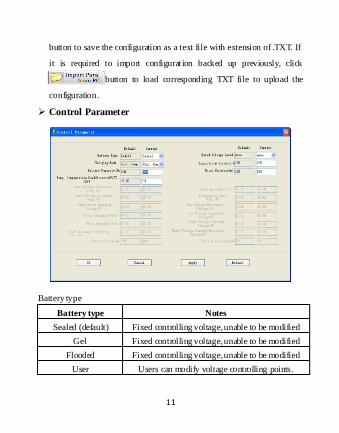
button to save the configuration as a text file with extension of .TXT. If
it is required to import configurat ion backed up previously, click
button to load corresponding TXT file to upload the
configuration.
Control Parameter
Battery type
Battery type Notes
Sealed (default) Fixed controlling voltage, unable to be modified
Gel Fixed controlling voltage, unable to be modified
Flooded Fixed controlling voltage, unable to be modified
User Users can modify voltage controlling points.
12
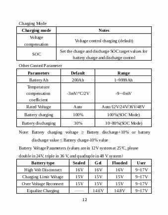
Charging Mode
Charging mode Notes
Voltage
compensation Voltage control charging (default)
SOC Set the charge and discharge SOC target values for
battery charge and discharge control
Other Control Parameter
Parameters Default Range
Battery Ah 200Ah 1~9999Ah
Temperature
compensation
coefficient
-3mV/ºC/2V -9~-0mV
Rated Voltage Auto Auto/12V/24V/36V/48V
Battery charging 100% 100%(SOC Mode)
Battery discharging 30% 10~80%(SOC Mode)
Note: Battery charging voltage ≥ Battery discharge+10% or battery
discharge value ≤ Battery charge-10% value
Battery Voltage Parameters (values are in 12V system at 25ºC, please
double in 24V, triple in 36 V, and quadruple in 48 V system)
Battery type Sealed Gel Flooded User
High Volt Disconnect 16V 16V 16V 9~17V
Charging Limit Voltage 15V 15V 15V 9~17V
Over Voltage Reconnect 15V 15V 15V 9~17V
Equalize Charging —— 14.6V 14.8V 9~17V
13
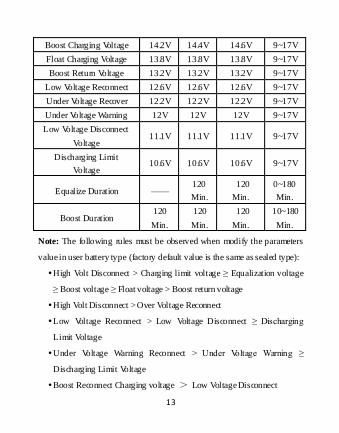
Boost Charging Voltage 14.2V 14.4V 14.6V 9~17V
Float Charging Voltage 13.8V 13.8V 13.8V 9~17V
Boost Return Voltage 13.2V 13.2V 13.2V 9~17V
Low Voltage Reconnect 12.6V 12.6V 12.6V 9~17V
Under Voltage Recover 12.2V 12.2V 12.2V 9~17V
Under Voltage Warning 12V 12V 12V 9~17V
Low Voltage Disconnect
Voltage 11.1V 11.1V 11.1V 9~17V
Discharging Limit
Voltage 10.6V 10.6V 10.6V 9~17V
Equalize Duration —— 120
Min.
120
Min.
0~180
Min.
Boost Duration 120
Min.
120
Min.
120
Min.
10~180
Min.
Note: The following rules must be observed when modify the parameters
value in user battery type (factory default value is the same as sealed type):
High Volt Disconnect > Charging limit voltage ≥ Equalization voltage
≥ Boost voltage ≥ Float voltage > Boost return voltage
High Volt Disconnect > Over Voltage Reconnect
Low Voltage Reconnect > Low Voltage Disconnect ≥ Discharging
Limit Voltage
Under Voltage Warning Reconnect > Under Voltage Warning ≥
Discharging Limit Voltage
Boost Reconnect Charging voltage > Low Voltage Disconnect
14
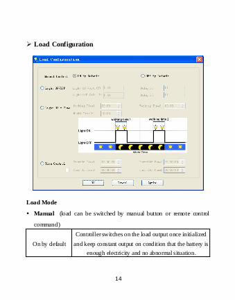
Load Configuration
Load Mode
Manual (load can be switched by manual button or remote control
command)
On by default
Controller switches on the load output once initialized
and keep constant output on condition that the battery is
enough electricity and no abnormal situation.
15
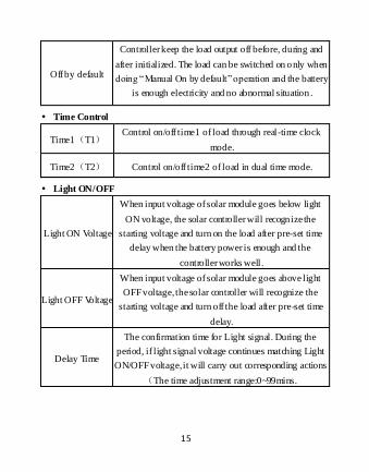
Off by default
Controller keep the load output off before, during and
after initialized. The load can be switched on only when
doing “Manual On by default” operation and the battery
is enough electricity and no abnormal situation .
Time Control
Time1(T1) Control on/off time1 of load through real-time clock
mode.
Time2(T2) Control on/off time2 of load in dual time mode.
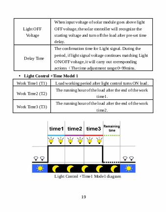
Light ON/OFF
Light ON Voltage
When input voltage of solar module goes below light
ON voltage, the solar controller will recognize the
starting voltage and turn on the load after pre-set time
delay when the battery power is enough and the
controller works well.
Light OFF Voltage
When input voltage of solar module goes above light
OFF voltage, the solar controller will recognize the
starting voltage and turn off the load after pre-set time
delay.
Delay Time
The confirmation time for Light signal. During the
period, if light signal voltage continues matching Light
ON/OFF voltage, it will carry out corresponding actions
(The time adjustment range:0~99mins.
16
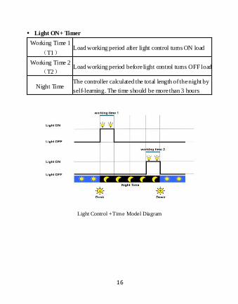
Light ON+ Timer
Working Time 1
(T1) Load working period after light control turns ON load
Working Time 2
(T2) Load working period before light control turns OFF load
Night Time The controller calculated the total length of the night by
self-learning. The time should be more than 3 hours
Light Control +Time Model Diagram
17
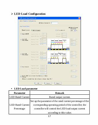
LED Load Configuration
LED Load parameter
Parameter Remark
LED Rated Current Rated output current.
LED Rated Current
Percentage
Set up the parameter of the rated current percentage of the
corresponding operating period of the controller; the
controller will control the LED load output current
according to this value.
18
Battery Under
Voltage Control
When the battery is under this voltage, the output current
will be half; when the voltage of the battery goes above it ,
the controller will resume the set current value
automatically.
Manual Control(load can be switched by manual button or remote
control command)
Manually On By
default
Controller switches on the load output once initialized
and keep constant output on condition that the battery
is enough electricity and no abnormal situation.
Manually Off
By default
Controller keep the load output off before, during and
after initialized. The load can be switched on only
when doing “Manual On by default” operation and the
battery is enough electricity and no abnormal situation.
Time Control
Time1(T1) Control on/off time1 of load through real -time clock
mode.
Time2(T2) Control on/off time2 of load in dual time mode.
Light ON/OFF
Light ON
Voltage
When input voltage of solar module goes below light
ON voltage, the solar controller will recognize the
starting voltage and turn on the load after pre-set time
delay when the battery power is enough and the
controller works well.
19
Light OFF
Voltage
When input voltage of solar module goes above light
OFF voltage, the solar controller will recognize the
starting voltage and turn off the load after pre-set time
delay.
Delay Time
The confirmation time for Light signal. During the
period, if light signal voltage continues matching Light
ON/OFF voltage, it will carry out corresponding
actions(The time adjustment range:0~99mins.
Light Control +Time Model 1
Work Time1 (T1) Load working period after light control turns ON load .
Work Time2 (T2) The running hour of the load after the end of the work
time1.
Work Time3 (T3) The running hour of the load after the end of the work
time2.
Light Control +Time1 Mode1 diagram
20
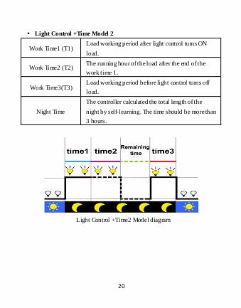
Light Control +Time Model 2
Work Time1 (T1) Load working period after light control turns ON
load.
Work Time2 (T2) The running hour of the load after the end of the
work time 1.
Work Time3(T3) Load working period before light control turns off
load.
Night Time
The controller calculated the total length of the
night by self-learning. The time should be more than
3 hours.
Light Control +Time2 Model diagram
21
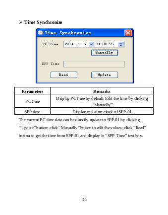
Time Synchronize
Parameters Remarks
PC time Display PC time by default; Edit the time by clicking
“Manually”.
SPP time Display real-time clock of SPP-01.
The current PC time data can be directly update to SPP-01 by clicking
“Update” button; click “Manually” button to edit the values; click “Read”
button to get the time from SPP-01 and display in “SPP Time” text box.
22
5 Specification
5.1 Hardware Configuration
Items Descriptions
Indicator light 1 green LED indicator
RTC clock
The real-time clock will not be lost when the
backup battery is installed. Please replace the
batteries when the time of SPP -01 is not correct.
Power supply
From three AAA (7#) batteries;
From Micro-USB cable via PC USB power;
From exclusive data cable via the controller.
Buzzer One built-in buzzer to prompt that communication
is right or wrong.
Communication port RJ11(TTL), RJ45(RS485), Micro-USB(USB).
5.2 SPP-01 Parameter
Parameter Rated
Power Supply Voltage 5.0V
Static Current < 40 mA
Communication Baud 115200bps
Working temperature -25ºC~+55ºC
Enclosure IP30
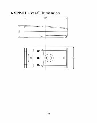
Overall dimension 109 mm *60 mm *33mm Net weight 80.1g
23
6 SPP-01 Overall Dimension


![POWER QUALITY IMPROVEMENT OF PHOTOVOLTAIC ...parameters [14] are given in Table-3. Table- 3. Three phase induction motor parameters. Parameter Value Rated Power 4 Kw Rated Line to](https://img.pdfslide.net/doc/110x75/607a744e9e3a7a017a48e4d1/power-quality-improvement-of-photovoltaic-parameters-14-are-given-in-table-3.jpg)