Embed Size (px)
Citation preview
SRS-1
SUPPLEMENTAL RESTRAINT SYSTEM (SRS)
H RESTRAINTS
CONTENTS
C
D
E
F
G
I
J
K
L
M
SECTION SRSA
B
SRS
Revision: 2004 November 2004 Murano
SUPPLEMENTAL RESTRAINT SYSTEM (SRS)
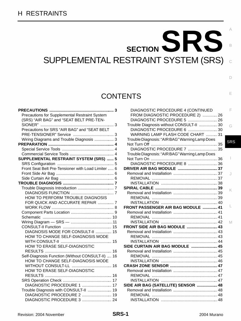
PRECAUTIONS .......................................................... 3Precautions for Supplemental Restraint System (SRS) “AIR BAG” and “SEAT BELT PRE-TEN-SIONER” .................................................................. 3Precautions for SRS “AIR BAG” and “SEAT BELT PRE-TENSIONER” Service ..................................... 3Wiring Diagrams and Trouble Diagnosis .................. 3
PREPARATION ........................................................... 4Special Service Tools ............................................... 4Commercial Service Tools ........................................ 4
SUPPLEMENTAL RESTRAINT SYSTEM (SRS) ....... 5SRS Configuration ................................................... 5Front Seat Belt Pre-Tensioner with Load Limiter ...... 6Front Side Air Bag .................................................... 6Side Curtain Air Bag ................................................. 6
TROUBLE DIAGNOSIS .............................................. 7Trouble Diagnosis Introduction ................................. 7
DIAGNOSIS FUNCTION ....................................... 7HOW TO PERFORM TROUBLE DIAGNOSIS FOR QUICK AND ACCURATE REPAIR ............... 7WORK FLOW ........................................................ 8
Component Parts Location ....................................... 9Schematic .............................................................. 10Wiring Diagram — SRS — ......................................11CONSULT-II Function ............................................ 15
DIAGNOSIS MODE FOR CONSULT-II ............... 15HOW TO CHANGE SELF-DIAGNOSIS MODE WITH CONSULT-II .............................................. 15HOW TO ERASE SELF-DIAGNOSTIC RESULTS ............................................................ 16
Self-Diagnosis Function (Without CONSULT-II) ..... 16HOW TO CHANGE SELF-DIAGNOSIS MODE WITHOUT CONSULT-LL .................................... 16HOW TO ERASE SELF-DIAGNOSTIC RESULTS ............................................................ 16
SRS Operation Check ............................................ 17DIAGNOSTIC PROCEDURE 1 ........................... 17
Trouble Diagnosis with CONSULT-II ...................... 19DIAGNOSTIC PROCEDURE 2 ........................... 19DIAGNOSTIC PROCEDURE 3 ........................... 24
DIAGNOSTIC PROCEDURE 4 (CONTINUED FROM DIAGNOSTIC PROCEDURE 2) .............. 26DIAGNOSTIC PROCEDURE 5 ........................... 26
Trouble Diagnosis without CONSULT-II ................. 30DIAGNOSTIC PROCEDURE 6 ........................... 30WARNING LAMP FLASH CODE CHART ........... 31
Trouble Diagnosis: “AIR BAG” Warning Lamp Does Not Turn Off ............................................................ 35
DIAGNOSTIC PROCEDURE 7 ........................... 35Trouble Diagnosis: “AIR BAG” Warning Lamp Does Not Turn On ............................................................ 36
DIAGNOSTIC PROCEDURE 8 ........................... 36DRIVER AIR BAG MODULE .................................... 37
Removal and Installation ........................................ 37REMOVAL ........................................................... 37INSTALLATION ................................................... 38
SPIRAL CABLE ........................................................ 39Removal and Installation ........................................ 39
REMOVAL ........................................................... 39INSTALLATION ................................................... 40
FRONT PASSENGER AIR BAG MODULE .............. 41Removal and Installation ........................................ 41
REMOVAL ........................................................... 41INSTALLATION ................................................... 42
FRONT SIDE AIR BAG MODULE ............................ 43Removal and Installation ........................................ 43
REMOVAL ........................................................... 43INSTALLATION ................................................... 44
SIDE CURTAIN AIR BAG MODULE ........................ 45Removal and Installation ........................................ 45
REMOVAL ........................................................... 45INSTALLATION ................................................... 46
CRASH ZONE SENSOR ........................................... 47Removal and Installation ........................................ 47
REMOVAL ........................................................... 47INSTALLATION ................................................... 47
SIDE AIR BAG (SATELLITE) SENSOR ................... 48Removal and Installation ........................................ 48
REMOVAL ........................................................... 48INSTALLATION ................................................... 48
SRS-2Revision: 2004 November 2004 Murano
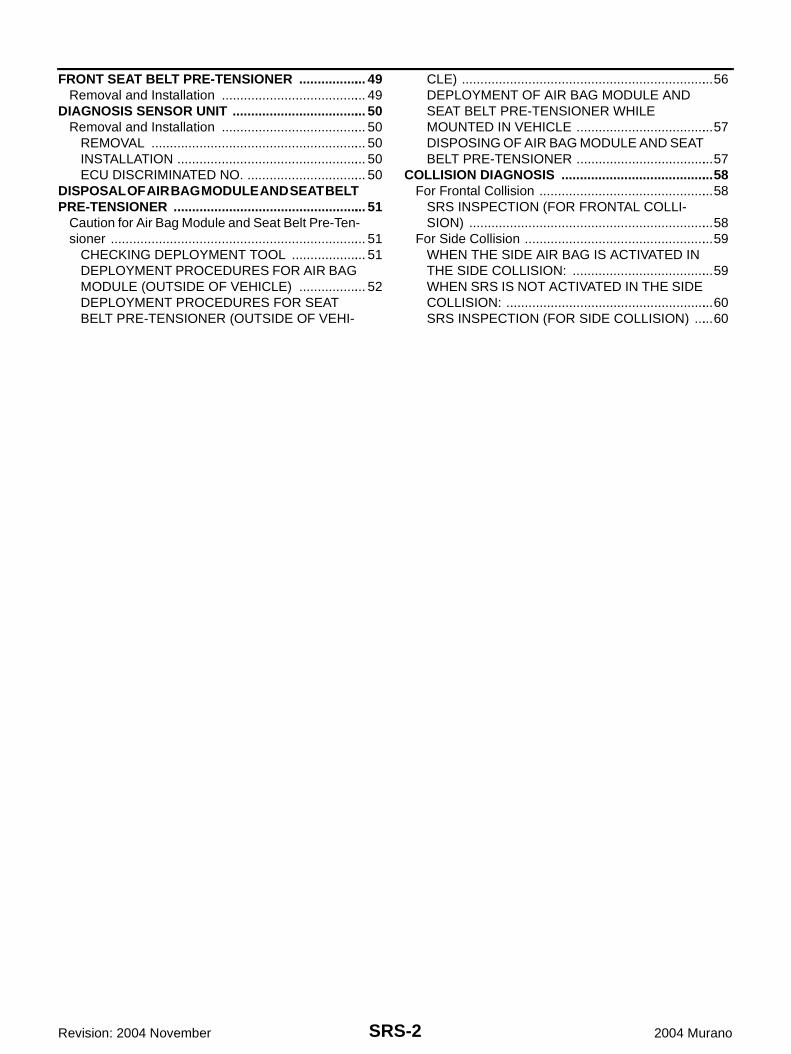
FRONT SEAT BELT PRE-TENSIONER ................... 49Removal and Installation ........................................ 49
DIAGNOSIS SENSOR UNIT ..................................... 50Removal and Installation ........................................ 50
REMOVAL ........................................................... 50INSTALLATION .................................................... 50ECU DISCRIMINATED NO. ................................. 50
DISPOSAL OF AIR BAG MODULE AND SEAT BELT PRE-TENSIONER ..................................................... 51
Caution for Air Bag Module and Seat Belt Pre-Ten-sioner ...................................................................... 51
CHECKING DEPLOYMENT TOOL ..................... 51DEPLOYMENT PROCEDURES FOR AIR BAG MODULE (OUTSIDE OF VEHICLE) ................... 52DEPLOYMENT PROCEDURES FOR SEAT BELT PRE-TENSIONER (OUTSIDE OF VEHI-
CLE) .....................................................................56DEPLOYMENT OF AIR BAG MODULE AND SEAT BELT PRE-TENSIONER WHILE MOUNTED IN VEHICLE ......................................57DISPOSING OF AIR BAG MODULE AND SEAT BELT PRE-TENSIONER ......................................57
COLLISION DIAGNOSIS ..........................................58For Frontal Collision ................................................58
SRS INSPECTION (FOR FRONTAL COLLI-SION) ...................................................................58
For Side Collision ....................................................59WHEN THE SIDE AIR BAG IS ACTIVATED IN THE SIDE COLLISION: .......................................59WHEN SRS IS NOT ACTIVATED IN THE SIDE COLLISION: .........................................................60SRS INSPECTION (FOR SIDE COLLISION) ......60
PRECAUTIONS
SRS-3
C
D
E
F
G
I
J
K
L
M
A
B
SRS
Revision: 2004 November 2004 Murano
PRECAUTIONS PFP:00001
Precautions for Supplemental Restraint System (SRS) “AIR BAG” and “SEAT BELT PRE-TENSIONER” AHS000AG
The Supplemental Restraint System such as “AIR BAG” and “SEAT BELT PRE-TENSIONER”, used alongwith a front seat belt, helps to reduce the risk or severity of injury to the driver and front passenger for certaintypes of collision. This system includes seat belt switch inputs and dual stage front air bag modules. The SRSsystem uses the seat belt switches to determine the front air bag deployment, and may only deploy one frontair bag, depending on the severity of a collision and whether the front occupants are belted or unbelted.Information necessary to service the system safely is included in the SRS and SB section of this Service Man-ual.WARNING:● To avoid rendering the SRS inoperative, which could increase the risk of personal injury or death
in the event of a collision which would result in air bag inflation, all maintenance must be per-formed by an authorized NISSAN/INFINITI dealer.
● Improper maintenance, including incorrect removal and installation of the SRS, can lead to per-sonal injury caused by unintentional activation of the system. For removal of Spiral Cable and AirBag Module, see the SRS section.
● Do not use electrical test equipment on any circuit related to the SRS unless instructed to in thisService Manual. SRS wiring harnesses can be identified by yellow and/or orange harnesses orharness connectors.
Precautions for SRS “AIR BAG” and “SEAT BELT PRE-TENSIONER” ServiceAHS000AH
● Do not use electrical test equipment to check SRS circuits unless instructed to in this Service Manual.● Before servicing the SRS, turn ignition switch OFF, disconnect both battery cables and wait at least 3 min-
utes.For approximately 3 minutes after the cables are removed, it is still possible for the air bag and seat beltpre-tensioner to deploy. Therefore, do not work on any SRS connectors or wires until at least 3 minuteshave passed.
● Diagnosis sensor unit must always be installed with their arrow marks “⇐ ” pointing towards the front of thevehicle for proper operation. Also check diagnosis sensor unit for cracks, deformities or rust before instal-lation and replace as required.
● The spiral cable must be aligned with the neutral position since its rotations are limited. Do not attempt toturn steering wheel or column after removal of steering gear.
● Handle air bag module carefully. Always place driver and front passenger air bag modules with the padside facing upward and seat mounted front side air bag module standing with the stud bolt side facingdown.
● Conduct self-diagnosis to check entire SRS for proper function after replacing any components.● After air bag inflates, the front instrument panel assembly should be replaced if damaged.● Always replace instrument panel pad following front passenger air bag deployment.
Wiring Diagrams and Trouble Diagnosis AHS000RD
When you read wiring diagrams, refer to the following:● GI-14, "How to Read Wiring Diagrams" in GI section● PG-3, "POWER SUPPLY ROUTING CIRCUIT" in PG sectionWhen you perform trouble diagnosis, refer to the following:● GI-10, "HOW TO FOLLOW TEST GROUPS IN TROUBLE DIAGNOSES" in GI section● GI-26, "How to Perform Efficient Diagnosis for an Electrical Incident" in GI sectionCheck for any service bulletins before servicing the vehicle.
SRS-4
PREPARATION
Revision: 2004 November 2004 Murano
PREPARATION PFP:00002
Special Service Tools AHS000E3
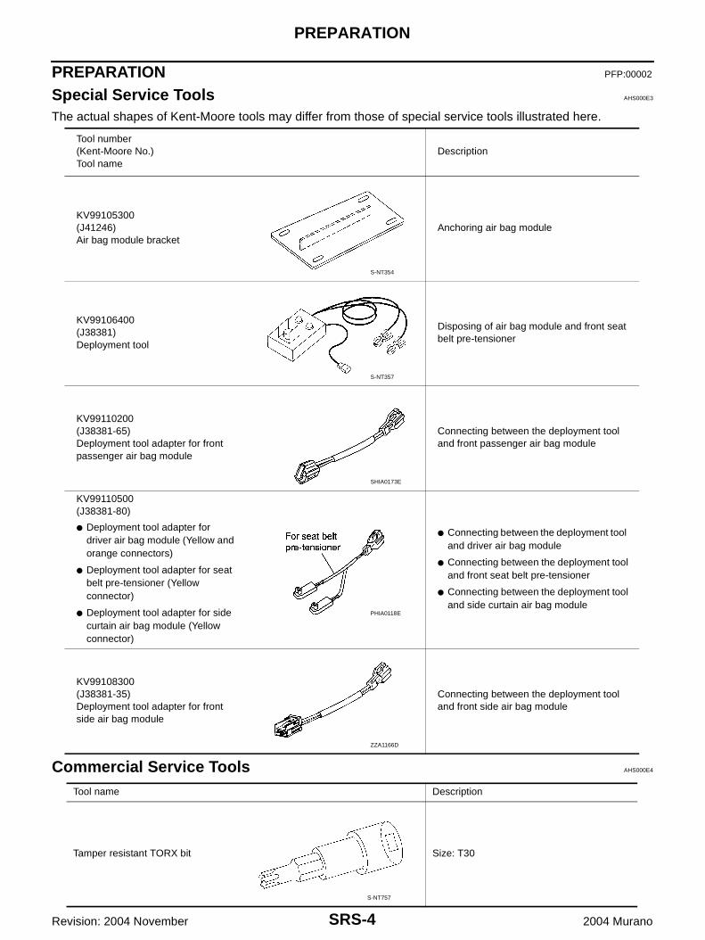
The actual shapes of Kent-Moore tools may differ from those of special service tools illustrated here.
Commercial Service Tools AHS000E4
Tool number(Kent-Moore No.)Tool name
Description
KV99105300(J41246)Air bag module bracket
Anchoring air bag module
KV99106400(J38381)Deployment tool
Disposing of air bag module and front seat belt pre-tensioner
KV99110200(J38381-65)Deployment tool adapter for front passenger air bag module
Connecting between the deployment tool and front passenger air bag module
KV99110500(J38381-80)
● Deployment tool adapter for driver air bag module (Yellow and orange connectors)
● Deployment tool adapter for seat belt pre-tensioner (Yellow connector)
● Deployment tool adapter for side curtain air bag module (Yellow connector)
● Connecting between the deployment tool and driver air bag module
● Connecting between the deployment tool and front seat belt pre-tensioner
● Connecting between the deployment tool and side curtain air bag module
KV99108300(J38381-35)Deployment tool adapter for front side air bag module
Connecting between the deployment tool and front side air bag module
S-NT354
S-NT357
SHIA0173E
PHIA0118E
ZZA1166D
Tool name Description
Tamper resistant TORX bit Size: T30
S-NT757
SUPPLEMENTAL RESTRAINT SYSTEM (SRS)
SRS-5
C
D
E
F
G
I
J
K
L
M
A
B
SRS
Revision: 2004 November 2004 Murano
SUPPLEMENTAL RESTRAINT SYSTEM (SRS) PFP:28556
SRS Configuration AHS000AM
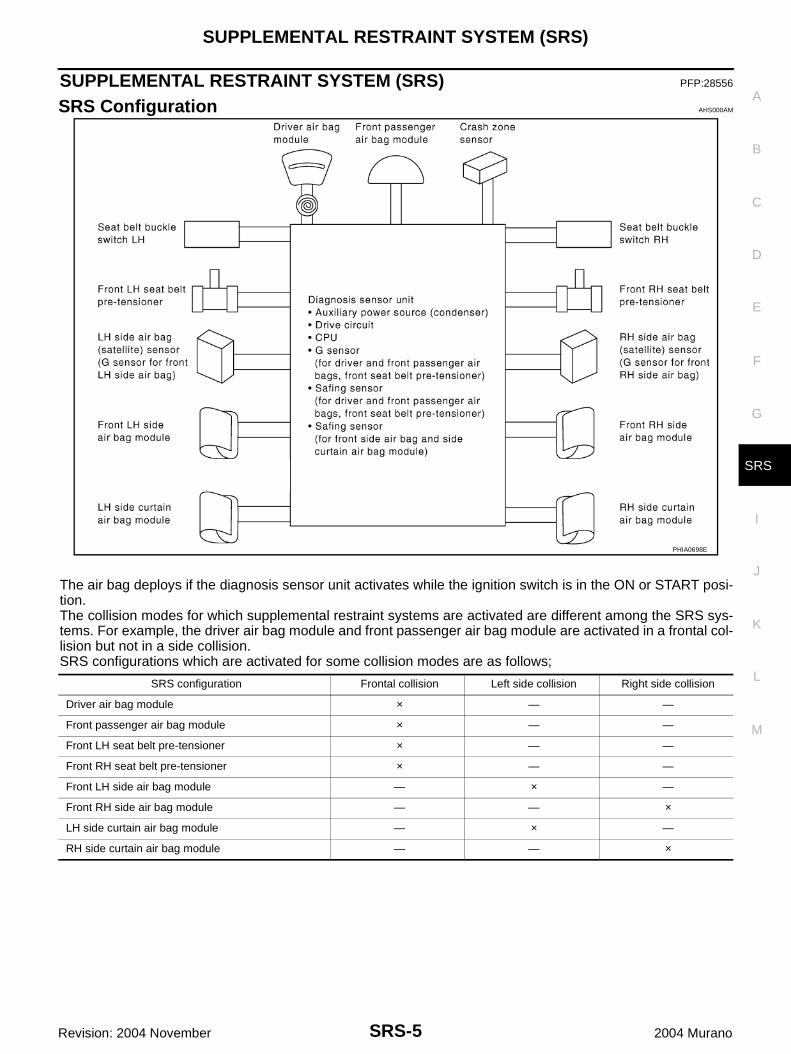
The air bag deploys if the diagnosis sensor unit activates while the ignition switch is in the ON or START posi-tion.The collision modes for which supplemental restraint systems are activated are different among the SRS sys-tems. For example, the driver air bag module and front passenger air bag module are activated in a frontal col-lision but not in a side collision.SRS configurations which are activated for some collision modes are as follows;
PHIA0698E
SRS configuration Frontal collision Left side collision Right side collision
Driver air bag module × — —
Front passenger air bag module × — —
Front LH seat belt pre-tensioner × — —
Front RH seat belt pre-tensioner × — —
Front LH side air bag module — × —
Front RH side air bag module — — ×
LH side curtain air bag module — × —
RH side curtain air bag module — — ×
SRS-6
SUPPLEMENTAL RESTRAINT SYSTEM (SRS)
Revision: 2004 November 2004 Murano
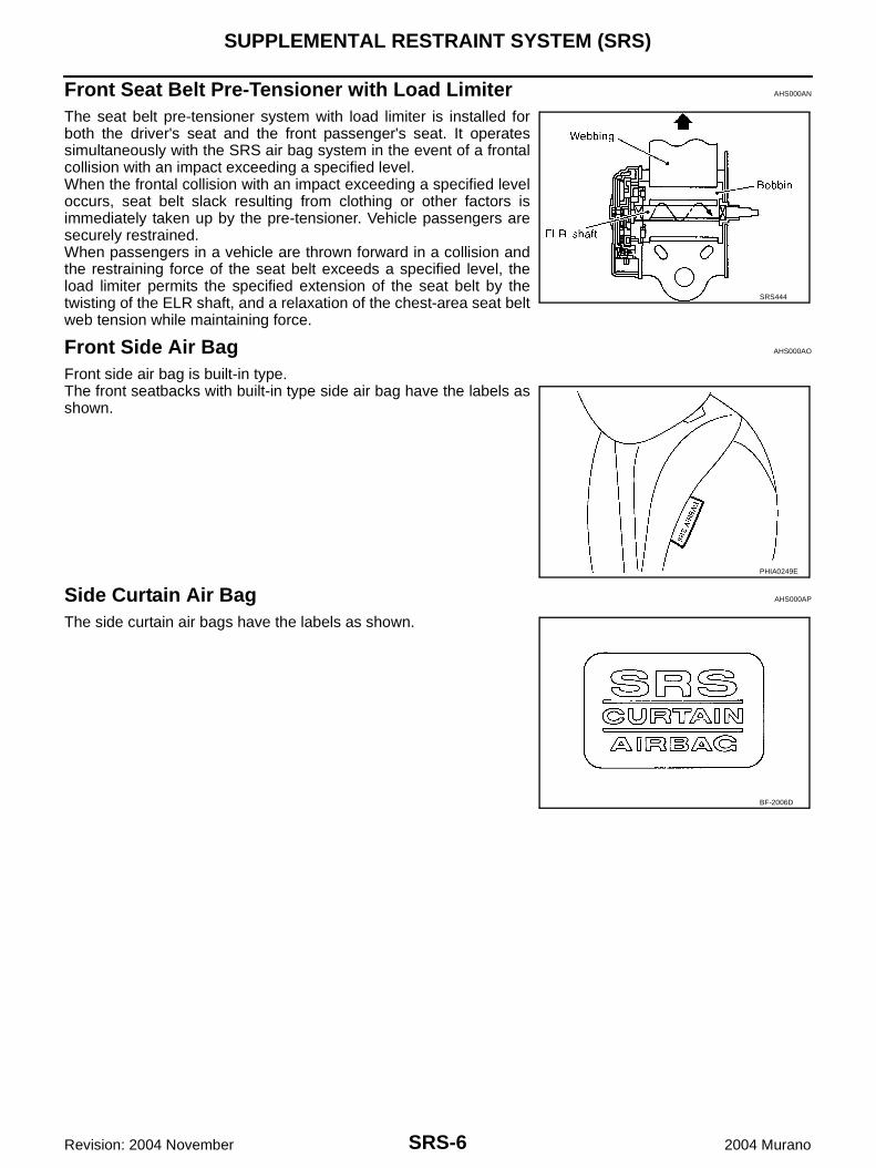
Front Seat Belt Pre-Tensioner with Load Limiter AHS000AN
The seat belt pre-tensioner system with load limiter is installed forboth the driver's seat and the front passenger's seat. It operatessimultaneously with the SRS air bag system in the event of a frontalcollision with an impact exceeding a specified level.When the frontal collision with an impact exceeding a specified leveloccurs, seat belt slack resulting from clothing or other factors isimmediately taken up by the pre-tensioner. Vehicle passengers aresecurely restrained.When passengers in a vehicle are thrown forward in a collision andthe restraining force of the seat belt exceeds a specified level, theload limiter permits the specified extension of the seat belt by thetwisting of the ELR shaft, and a relaxation of the chest-area seat beltweb tension while maintaining force.
Front Side Air Bag AHS000AO
Front side air bag is built-in type.The front seatbacks with built-in type side air bag have the labels asshown.
Side Curtain Air Bag AHS000AP
The side curtain air bags have the labels as shown.
SRS444
PHIA0249E
BF-2006D
TROUBLE DIAGNOSIS
SRS-7
C
D
E
F
G
I
J
K
L
M
A
B
SRS
Revision: 2004 November 2004 Murano
TROUBLE DIAGNOSIS PFP:00004
Trouble Diagnosis Introduction AHS000E5
CAUTION:● Do not use electrical test equipment on any circuit related to the SRS unless instructed in this Ser-
vice Manual. SRS wiring harnesses can be identified by yellow and/or orange harnesses or har-ness connectors.
● Do not repair, splice or modify the SRS wiring harness. If the harness is damaged, replace it with anew one.
● Keep ground portion clean.
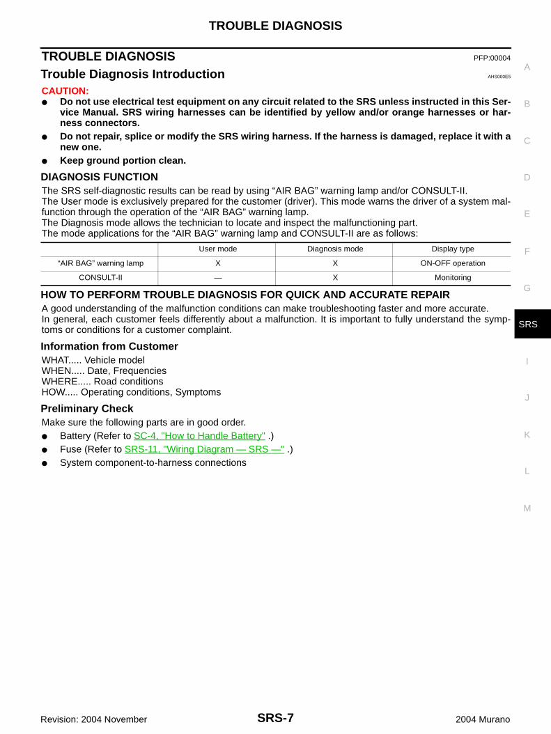
DIAGNOSIS FUNCTIONThe SRS self-diagnostic results can be read by using “AIR BAG” warning lamp and/or CONSULT-II.The User mode is exclusively prepared for the customer (driver). This mode warns the driver of a system mal-function through the operation of the “AIR BAG” warning lamp.The Diagnosis mode allows the technician to locate and inspect the malfunctioning part.The mode applications for the “AIR BAG” warning lamp and CONSULT-II are as follows:
HOW TO PERFORM TROUBLE DIAGNOSIS FOR QUICK AND ACCURATE REPAIRA good understanding of the malfunction conditions can make troubleshooting faster and more accurate.In general, each customer feels differently about a malfunction. It is important to fully understand the symp-toms or conditions for a customer complaint.
Information from CustomerWHAT..... Vehicle modelWHEN..... Date, FrequenciesWHERE..... Road conditionsHOW..... Operating conditions, Symptoms
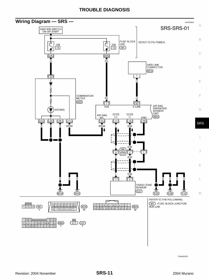
Preliminary CheckMake sure the following parts are in good order.● Battery (Refer to SC-4, "How to Handle Battery" .)● Fuse (Refer to SRS-11, "Wiring Diagram — SRS —" .)● System component-to-harness connections
User mode Diagnosis mode Display type
“AIR BAG” warning lamp X X ON-OFF operation
CONSULT-II — X Monitoring
SRS-8
TROUBLE DIAGNOSIS
Revision: 2004 November 2004 Murano
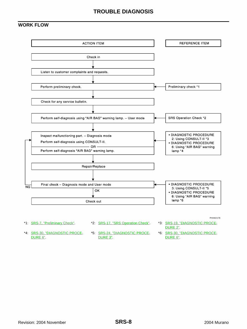
WORK FLOW
*1: SRS-7, "Preliminary Check". *2: SRS-17, "SRS Operation Check". *3: SRS-19, "DIAGNOSTIC PROCE-DURE 2".
*4: SRS-30, "DIAGNOSTIC PROCE-DURE 6".
*5: SRS-24, "DIAGNOSTIC PROCE-DURE 3".
*6: SRS-30, "DIAGNOSTIC PROCE-DURE 6".
PHIA0217E
TROUBLE DIAGNOSIS
SRS-9
C
D
E
F
G
I
J
K
L
M
A
B
SRS
Revision: 2004 November 2004 Murano
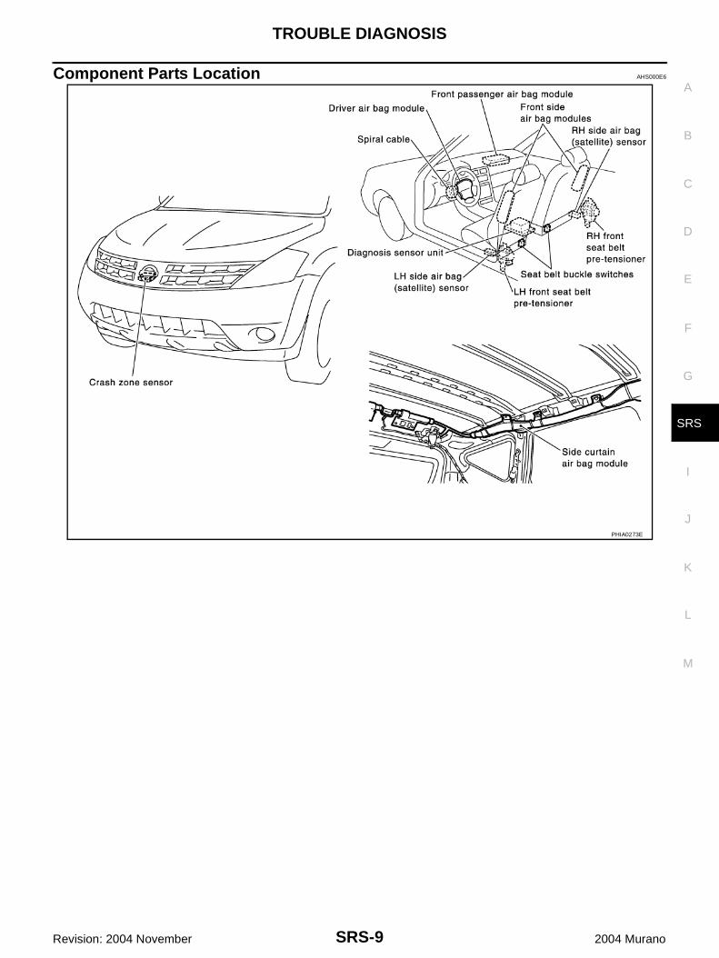
Component Parts Location AHS000E6
PHIA0273E
SRS-10
TROUBLE DIAGNOSIS
Revision: 2004 November 2004 Murano
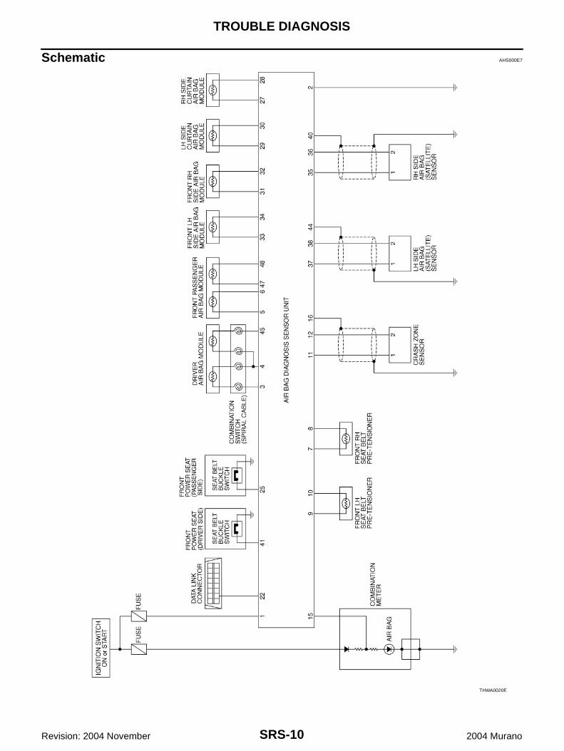
Schematic AHS000E7
THWA0020E
TROUBLE DIAGNOSIS
SRS-11
C
D
E
F
G
I
J
K
L
M
A
B
SRS
Revision: 2004 November 2004 Murano
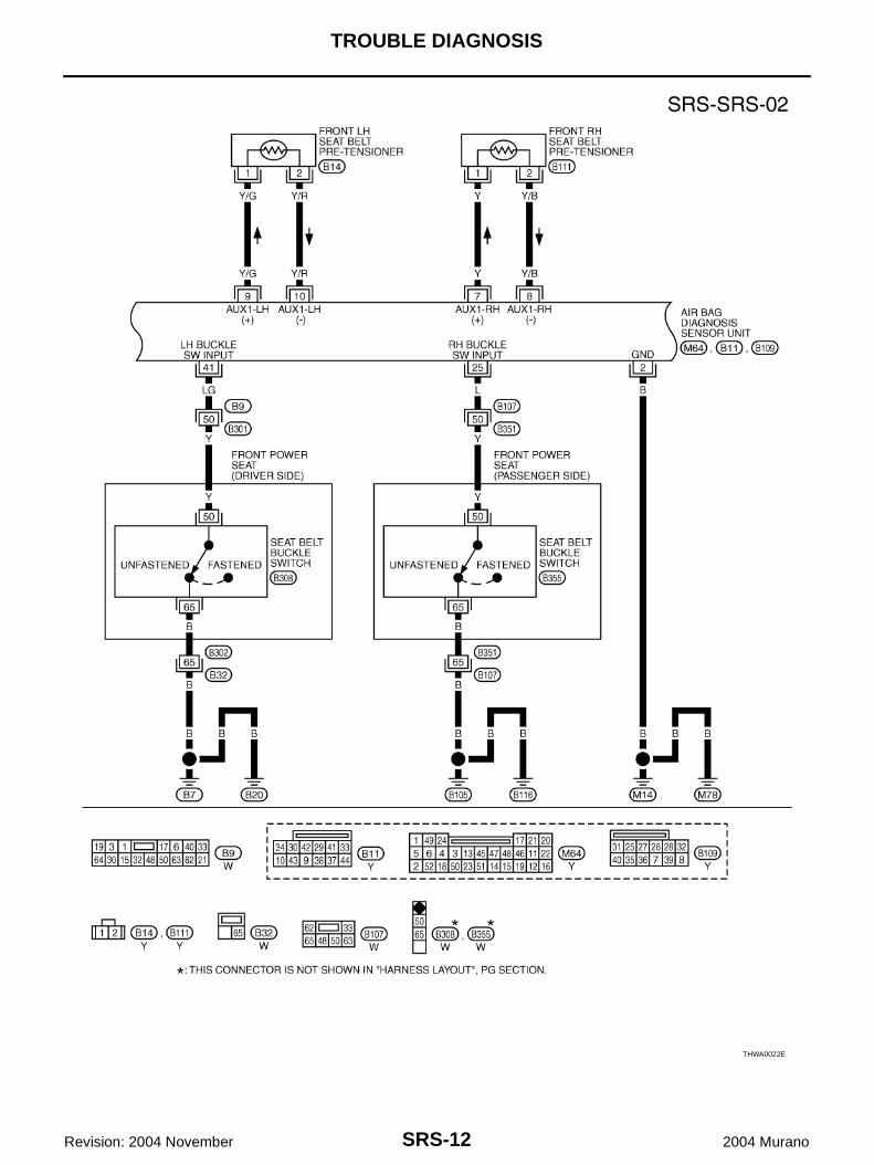
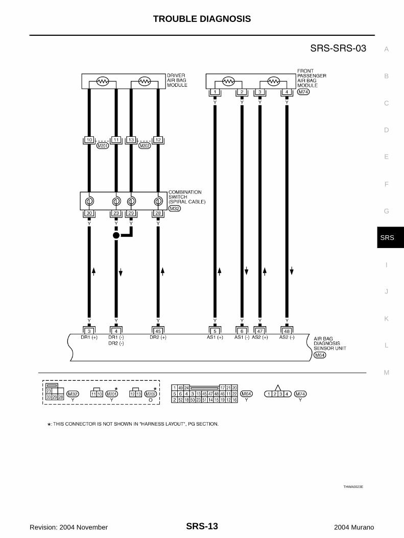
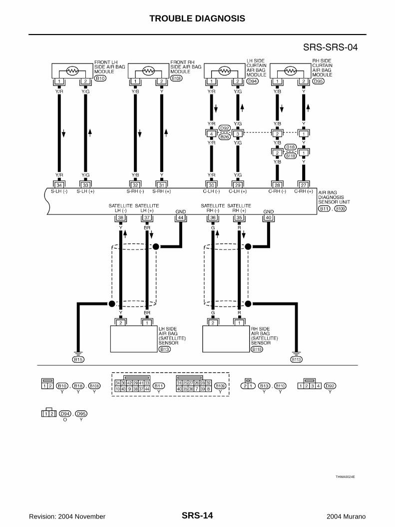
Wiring Diagram — SRS — AHS000E8
THWA0025E
SRS-12
TROUBLE DIAGNOSIS
Revision: 2004 November 2004 Murano
THWA0022E
TROUBLE DIAGNOSIS
SRS-13
C
D
E
F
G
I
J
K
L
M
A
B
SRS
Revision: 2004 November 2004 Murano
THWA0023E
SRS-14
TROUBLE DIAGNOSIS
Revision: 2004 November 2004 Murano
THWA0024E
TROUBLE DIAGNOSIS
SRS-15
C
D
E
F
G
I
J
K
L
M
A
B
SRS
Revision: 2004 November 2004 Murano
CONSULT-II Function AHS000E9
DIAGNOSIS MODE FOR CONSULT-II● “SELF-DIAG [CURRENT]”
A current self-diagnostic results (also indicated by the number of warning lamp flashes in the Diagnosismode) is displayed on the CONSULT-II screen in real time. This refers to a malfunctioning part requiringrepairs.
● “SELF-DIAG [PAST]”Diagnosis results previously stored in the memory are displayed on the CONSULT-II screen. The storedresults are not erased until memory erasing is executed.
● “TROUBLE DIAG RECORD”With TROUBLE DIAG RECORD, diagnosis results previously erased by a reset operation can be dis-played on the CONSULT-II screen.
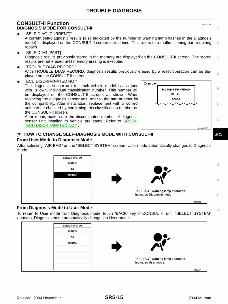
● “ECU DISCRIMINATED NO.”The diagnosis sensor unit for each vehicle model is assignedwith its own, individual classification number. This number willbe displayed on the CONSULT-II screen, as shown. Whenreplacing the diagnosis sensor unit, refer to the part number forthe compatibility. After installation, replacement with a correctunit can be checked by confirming this classification number onthe CONSULT-II screen.After repair, make sure the discriminated number of diagnosissensor unit installed to vehicle are same. Refer to SRS-50,"ECU DISCRIMINATED NO." .
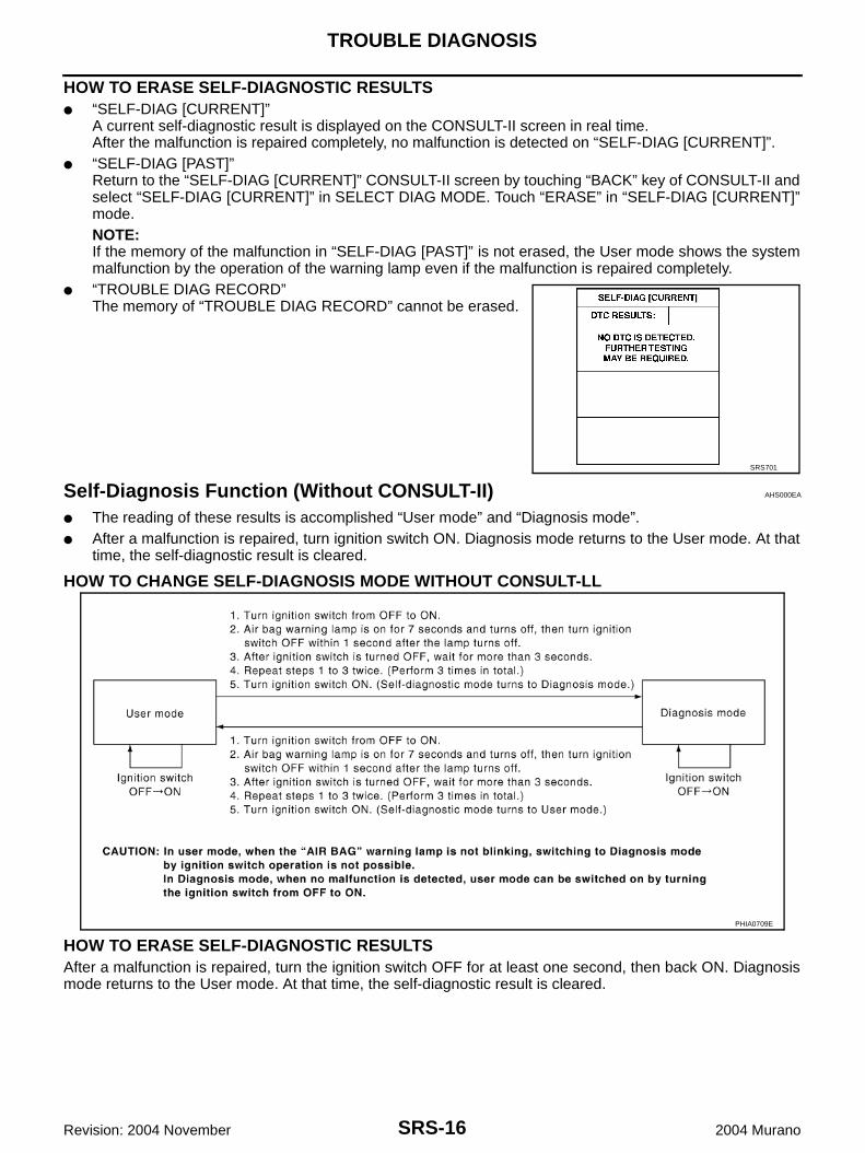
HOW TO CHANGE SELF-DIAGNOSIS MODE WITH CONSULT-IIFrom User Mode to Diagnosis ModeAfter selecting “AIR BAG” on the “SELECT SYSTEM” screen, User mode automatically changes to Diagnosismode.
From Diagnosis Mode to User ModeTo return to User mode from Diagnosis mode, touch “BACK” key of CONSULT-II until “SELECT SYSTEM”appears, Diagnosis mode automatically changes to User mode.
PHIA0218E
SRS803
SRS804
SRS-16
TROUBLE DIAGNOSIS
Revision: 2004 November 2004 Murano
HOW TO ERASE SELF-DIAGNOSTIC RESULTS● “SELF-DIAG [CURRENT]”
A current self-diagnostic result is displayed on the CONSULT-II screen in real time.After the malfunction is repaired completely, no malfunction is detected on “SELF-DIAG [CURRENT]”.
● “SELF-DIAG [PAST]”Return to the “SELF-DIAG [CURRENT]” CONSULT-II screen by touching “BACK” key of CONSULT-II andselect “SELF-DIAG [CURRENT]” in SELECT DIAG MODE. Touch “ERASE” in “SELF-DIAG [CURRENT]”mode.NOTE:If the memory of the malfunction in “SELF-DIAG [PAST]” is not erased, the User mode shows the systemmalfunction by the operation of the warning lamp even if the malfunction is repaired completely.
● “TROUBLE DIAG RECORD”The memory of “TROUBLE DIAG RECORD” cannot be erased.
Self-Diagnosis Function (Without CONSULT-II) AHS000EA
● The reading of these results is accomplished “User mode” and “Diagnosis mode”.● After a malfunction is repaired, turn ignition switch ON. Diagnosis mode returns to the User mode. At that
time, the self-diagnostic result is cleared.
HOW TO CHANGE SELF-DIAGNOSIS MODE WITHOUT CONSULT-LL
HOW TO ERASE SELF-DIAGNOSTIC RESULTSAfter a malfunction is repaired, turn the ignition switch OFF for at least one second, then back ON. Diagnosismode returns to the User mode. At that time, the self-diagnostic result is cleared.
SRS701
PHIA0709E
TROUBLE DIAGNOSIS
SRS-17
C
D
E
F
G
I
J
K
L
M
A
B
SRS
Revision: 2004 November 2004 Murano
SRS Operation Check AHS000EB
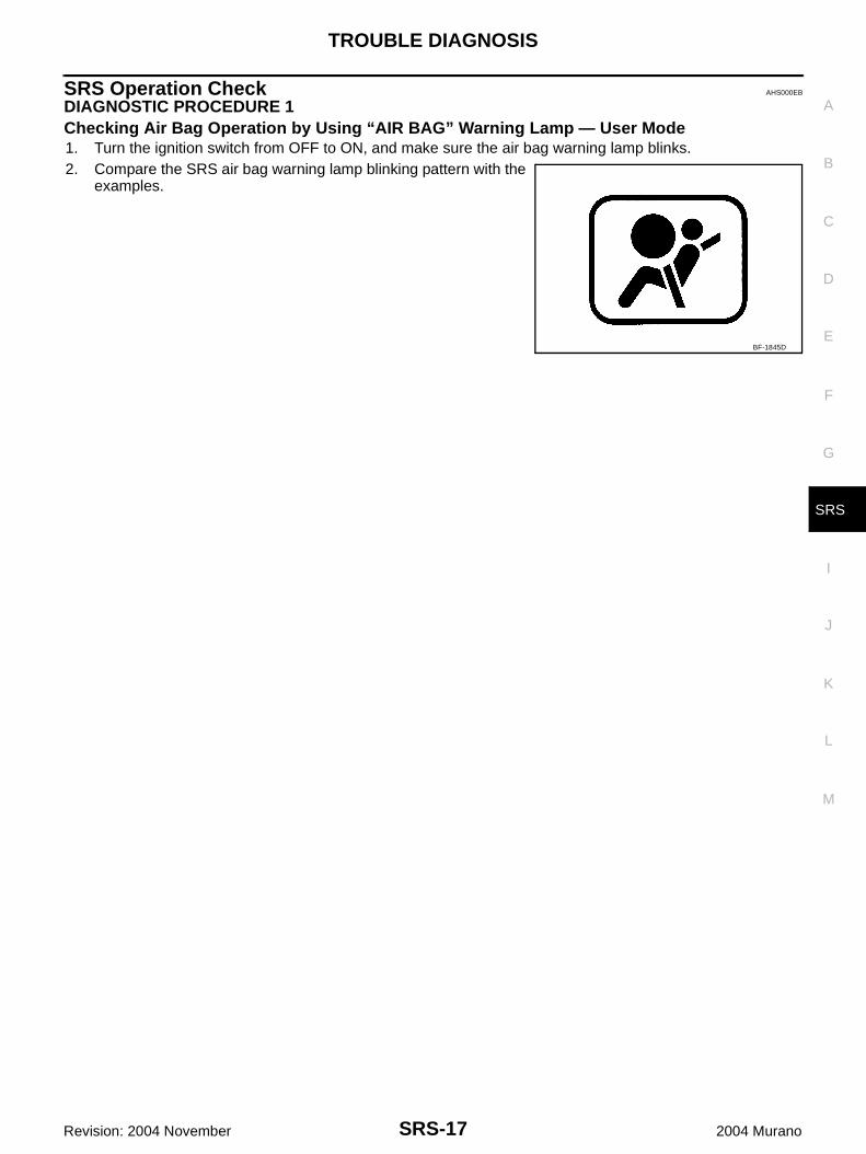
DIAGNOSTIC PROCEDURE 1Checking Air Bag Operation by Using “AIR BAG” Warning Lamp — User Mode1. Turn the ignition switch from OFF to ON, and make sure the air bag warning lamp blinks.2. Compare the SRS air bag warning lamp blinking pattern with the
examples.
BF-1845D
SRS-18
TROUBLE DIAGNOSIS
Revision: 2004 November 2004 Murano
Warning lamp examples
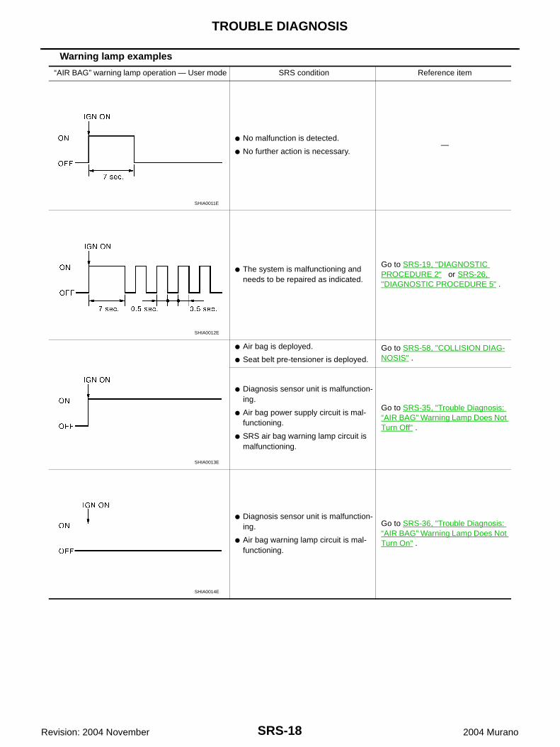
“AIR BAG” warning lamp operation — User mode SRS condition Reference item
● No malfunction is detected.
● No further action is necessary.—
● The system is malfunctioning and needs to be repaired as indicated.
Go to SRS-19, "DIAGNOSTIC PROCEDURE 2" or SRS-26, "DIAGNOSTIC PROCEDURE 5" .
● Air bag is deployed.
● Seat belt pre-tensioner is deployed.
Go to SRS-58, "COLLISION DIAG-NOSIS" .
● Diagnosis sensor unit is malfunction-ing.
● Air bag power supply circuit is mal-functioning.
● SRS air bag warning lamp circuit is malfunctioning.
Go to SRS-35, "Trouble Diagnosis: “AIR BAG” Warning Lamp Does Not Turn Off" .
● Diagnosis sensor unit is malfunction-ing.
● Air bag warning lamp circuit is mal-functioning.
Go to SRS-36, "Trouble Diagnosis: “AIR BAG” Warning Lamp Does Not Turn On" .
SHIA0011E
SHIA0012E
SHIA0013E
SHIA0014E
TROUBLE DIAGNOSIS
SRS-19
C
D
E
F
G
I
J
K
L
M
A
B
SRS
Revision: 2004 November 2004 Murano
Trouble Diagnosis with CONSULT-II AHS000EC
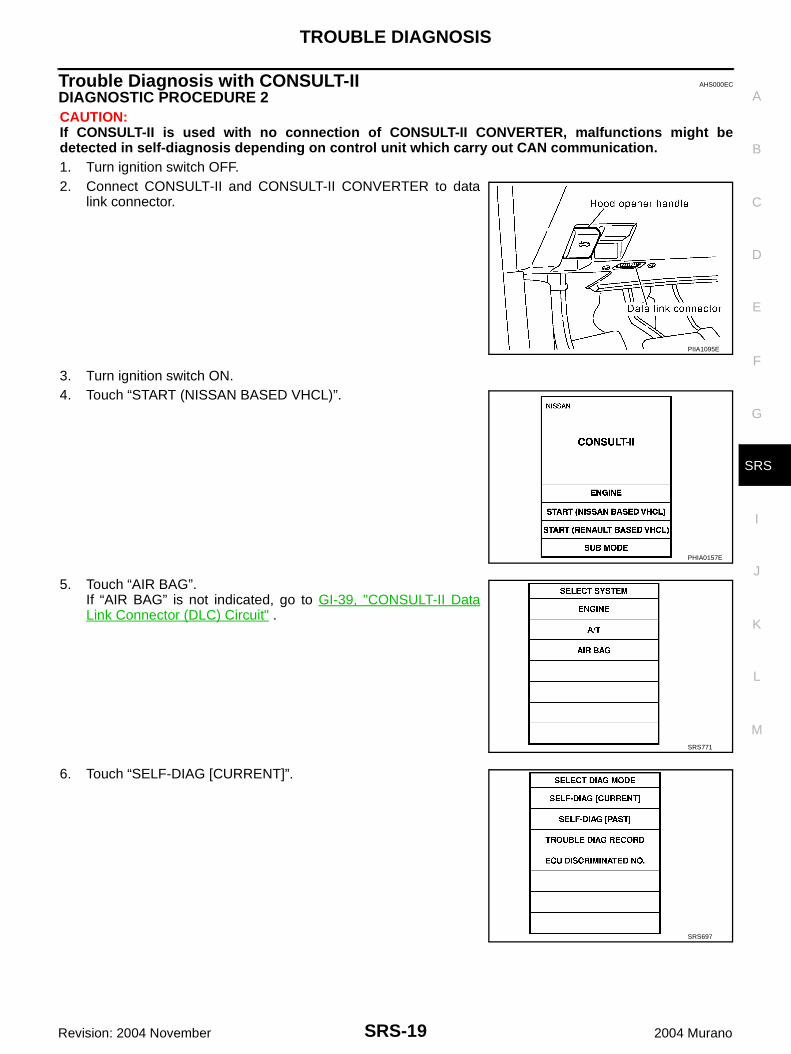
DIAGNOSTIC PROCEDURE 2CAUTION:If CONSULT-II is used with no connection of CONSULT-II CONVERTER, malfunctions might bedetected in self-diagnosis depending on control unit which carry out CAN communication.1. Turn ignition switch OFF.2. Connect CONSULT-II and CONSULT-II CONVERTER to data
link connector.
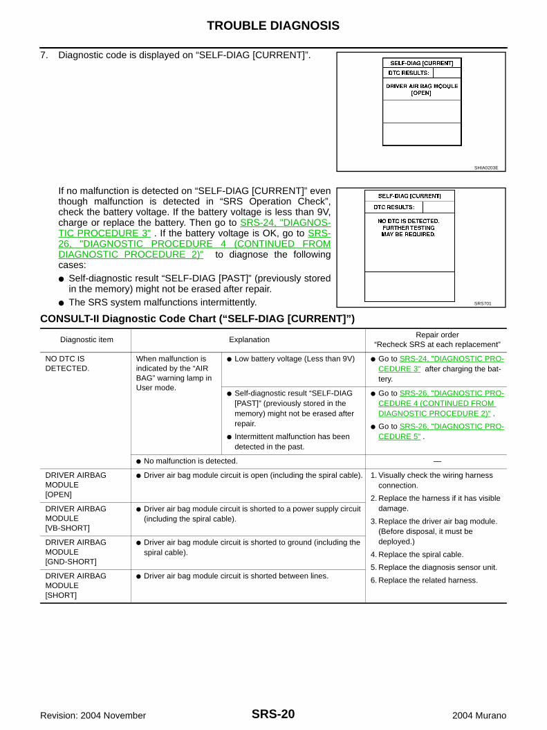
3. Turn ignition switch ON.4. Touch “START (NISSAN BASED VHCL)”.
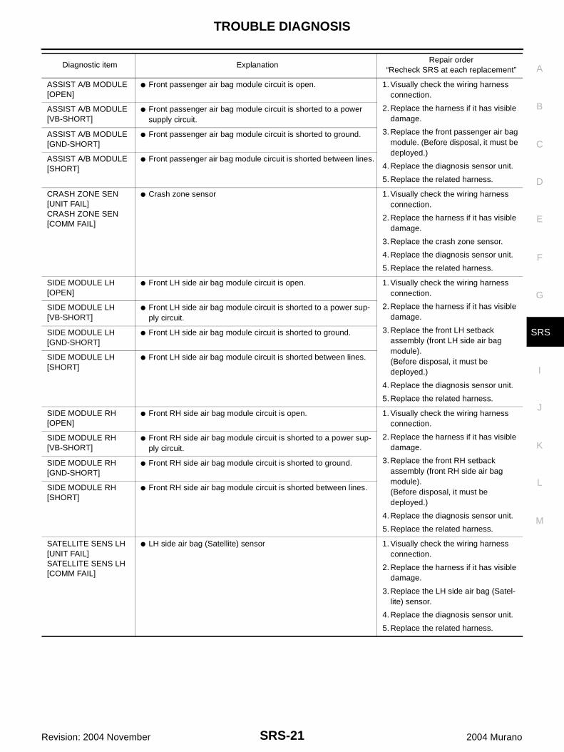
5. Touch “AIR BAG”.If “AIR BAG” is not indicated, go to GI-39, "CONSULT-II DataLink Connector (DLC) Circuit" .
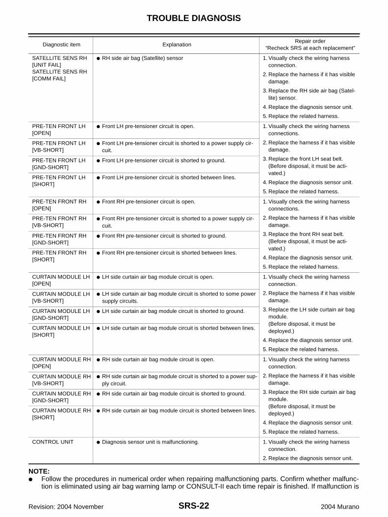
6. Touch “SELF-DIAG [CURRENT]”.
PIIA1095E
PHIA0157E
SRS771
SRS697
SRS-20
TROUBLE DIAGNOSIS
Revision: 2004 November 2004 Murano
7. Diagnostic code is displayed on “SELF-DIAG [CURRENT]”.
If no malfunction is detected on “SELF-DIAG [CURRENT]” eventhough malfunction is detected in “SRS Operation Check”,check the battery voltage. If the battery voltage is less than 9V,charge or replace the battery. Then go to SRS-24, "DIAGNOS-TIC PROCEDURE 3" . If the battery voltage is OK, go to SRS-26, "DIAGNOSTIC PROCEDURE 4 (CONTINUED FROMDIAGNOSTIC PROCEDURE 2)" to diagnose the followingcases:● Self-diagnostic result “SELF-DIAG [PAST]” (previously stored
in the memory) might not be erased after repair.● The SRS system malfunctions intermittently.
CONSULT-II Diagnostic Code Chart (“SELF-DIAG [CURRENT]”)
SHIA0203E
SRS701
Diagnostic item ExplanationRepair order
“Recheck SRS at each replacement”
NO DTC IS DETECTED.
When malfunction is indicated by the “AIR BAG” warning lamp in User mode.
● Low battery voltage (Less than 9V) ● Go to SRS-24, "DIAGNOSTIC PRO-CEDURE 3" after charging the bat-tery.
● Self-diagnostic result “SELF-DIAG [PAST]” (previously stored in the memory) might not be erased after repair.
● Intermittent malfunction has been detected in the past.
● Go to SRS-26, "DIAGNOSTIC PRO-CEDURE 4 (CONTINUED FROM DIAGNOSTIC PROCEDURE 2)" .
● Go to SRS-26, "DIAGNOSTIC PRO-CEDURE 5" .
● No malfunction is detected. —
DRIVER AIRBAG MODULE[OPEN]
● Driver air bag module circuit is open (including the spiral cable). 1. Visually check the wiring harness connection.
2. Replace the harness if it has visible damage.
3. Replace the driver air bag module. (Before disposal, it must be deployed.)
4. Replace the spiral cable.
5. Replace the diagnosis sensor unit.
6. Replace the related harness.
DRIVER AIRBAG MODULE[VB-SHORT]
● Driver air bag module circuit is shorted to a power supply circuit (including the spiral cable).
DRIVER AIRBAG MODULE[GND-SHORT]
● Driver air bag module circuit is shorted to ground (including the spiral cable).
DRIVER AIRBAG MODULE[SHORT]
● Driver air bag module circuit is shorted between lines.
TROUBLE DIAGNOSIS
SRS-21
C
D
E
F
G
I
J
K
L
M
A
B
SRS
Revision: 2004 November 2004 Murano
ASSIST A/B MODULE[OPEN]
● Front passenger air bag module circuit is open. 1. Visually check the wiring harness connection.
2. Replace the harness if it has visible damage.
3. Replace the front passenger air bag module. (Before disposal, it must be deployed.)
4. Replace the diagnosis sensor unit.
5. Replace the related harness.
ASSIST A/B MODULE[VB-SHORT]
● Front passenger air bag module circuit is shorted to a power supply circuit.
ASSIST A/B MODULE[GND-SHORT]
● Front passenger air bag module circuit is shorted to ground.
ASSIST A/B MODULE[SHORT]
● Front passenger air bag module circuit is shorted between lines.
CRASH ZONE SEN[UNIT FAIL]CRASH ZONE SEN[COMM FAIL]
● Crash zone sensor 1. Visually check the wiring harness connection.
2. Replace the harness if it has visible damage.
3. Replace the crash zone sensor.
4. Replace the diagnosis sensor unit.
5. Replace the related harness.
SIDE MODULE LH[OPEN]
● Front LH side air bag module circuit is open. 1. Visually check the wiring harness connection.
2. Replace the harness if it has visible damage.
3. Replace the front LH setback assembly (front LH side air bag module).(Before disposal, it must be deployed.)
4. Replace the diagnosis sensor unit.
5. Replace the related harness.
SIDE MODULE LH[VB-SHORT]
● Front LH side air bag module circuit is shorted to a power sup-ply circuit.
SIDE MODULE LH[GND-SHORT]
● Front LH side air bag module circuit is shorted to ground.
SIDE MODULE LH[SHORT]
● Front LH side air bag module circuit is shorted between lines.
SIDE MODULE RH[OPEN]
● Front RH side air bag module circuit is open. 1. Visually check the wiring harness connection.
2. Replace the harness if it has visible damage.
3. Replace the front RH setback assembly (front RH side air bag module).(Before disposal, it must be deployed.)
4. Replace the diagnosis sensor unit.
5. Replace the related harness.
SIDE MODULE RH[VB-SHORT]
● Front RH side air bag module circuit is shorted to a power sup-ply circuit.
SIDE MODULE RH[GND-SHORT]
● Front RH side air bag module circuit is shorted to ground.
SIDE MODULE RH[SHORT]
● Front RH side air bag module circuit is shorted between lines.
SATELLITE SENS LH[UNIT FAIL]SATELLITE SENS LH[COMM FAIL]
● LH side air bag (Satellite) sensor 1. Visually check the wiring harness connection.
2. Replace the harness if it has visible damage.
3. Replace the LH side air bag (Satel-lite) sensor.
4. Replace the diagnosis sensor unit.
5. Replace the related harness.
Diagnostic item ExplanationRepair order
“Recheck SRS at each replacement”
SRS-22
TROUBLE DIAGNOSIS
Revision: 2004 November 2004 Murano
NOTE:● Follow the procedures in numerical order when repairing malfunctioning parts. Confirm whether malfunc-
tion is eliminated using air bag warning lamp or CONSULT-II each time repair is finished. If malfunction is
SATELLITE SENS RH[UNIT FAIL]SATELLITE SENS RH[COMM FAIL]
● RH side air bag (Satellite) sensor 1. Visually check the wiring harness connection.
2. Replace the harness if it has visible damage.
3. Replace the RH side air bag (Satel-lite) sensor.
4. Replace the diagnosis sensor unit.
5. Replace the related harness.
PRE-TEN FRONT LH[OPEN]
● Front LH pre-tensioner circuit is open. 1. Visually check the wiring harness connections.
2. Replace the harness if it has visible damage.
3. Replace the front LH seat belt.(Before disposal, it must be acti-vated.)
4. Replace the diagnosis sensor unit.
5. Replace the related harness.
PRE-TEN FRONT LH[VB-SHORT]
● Front LH pre-tensioner circuit is shorted to a power supply cir-cuit.
PRE-TEN FRONT LH[GND-SHORT]
● Front LH pre-tensioner circuit is shorted to ground.
PRE-TEN FRONT LH[SHORT]
● Front LH pre-tensioner circuit is shorted between lines.
PRE-TEN FRONT RH[OPEN]
● Front RH pre-tensioner circuit is open. 1. Visually check the wiring harness connections.
2. Replace the harness if it has visible damage.
3. Replace the front RH seat belt.(Before disposal, it must be acti-vated.)
4. Replace the diagnosis sensor unit.
5. Replace the related harness.
PRE-TEN FRONT RH[VB-SHORT]
● Front RH pre-tensioner circuit is shorted to a power supply cir-cuit.
PRE-TEN FRONT RH[GND-SHORT]
● Front RH pre-tensioner circuit is shorted to ground.
PRE-TEN FRONT RH[SHORT]
● Front RH pre-tensioner circuit is shorted between lines.
CURTAIN MODULE LH[OPEN]
● LH side curtain air bag module circuit is open. 1. Visually check the wiring harness connection.
2. Replace the harness if it has visible damage.
3. Replace the LH side curtain air bag module.(Before disposal, it must be deployed.)
4. Replace the diagnosis sensor unit.
5. Replace the related harness.
CURTAIN MODULE LH[VB-SHORT]
● LH side curtain air bag module circuit is shorted to some power supply circuits.
CURTAIN MODULE LH[GND-SHORT]
● LH side curtain air bag module circuit is shorted to ground.
CURTAIN MODULE LH[SHORT]
● LH side curtain air bag module circuit is shorted between lines.
CURTAIN MODULE RH[OPEN]
● RH side curtain air bag module circuit is open. 1. Visually check the wiring harness connection.
2. Replace the harness if it has visible damage.
3. Replace the RH side curtain air bag module.(Before disposal, it must be deployed.)
4. Replace the diagnosis sensor unit.
5. Replace the related harness.
CURTAIN MODULE RH[VB-SHORT]
● RH side curtain air bag module circuit is shorted to a power sup-ply circuit.
CURTAIN MODULE RH[GND-SHORT]
● RH side curtain air bag module circuit is shorted to ground.
CURTAIN MODULE RH[SHORT]
● RH side curtain air bag module circuit is shorted between lines.
CONTROL UNIT ● Diagnosis sensor unit is malfunctioning. 1. Visually check the wiring harness connection.
2. Replace the diagnosis sensor unit.
Diagnostic item ExplanationRepair order
“Recheck SRS at each replacement”
TROUBLE DIAGNOSIS
SRS-23
C
D
E
F
G
I
J
K
L
M
A
B
SRS
Revision: 2004 November 2004 Murano
still observed, proceed to the next step. When malfunction is eliminated, further repair work is notrequired.
SRS-24
TROUBLE DIAGNOSIS
Revision: 2004 November 2004 Murano
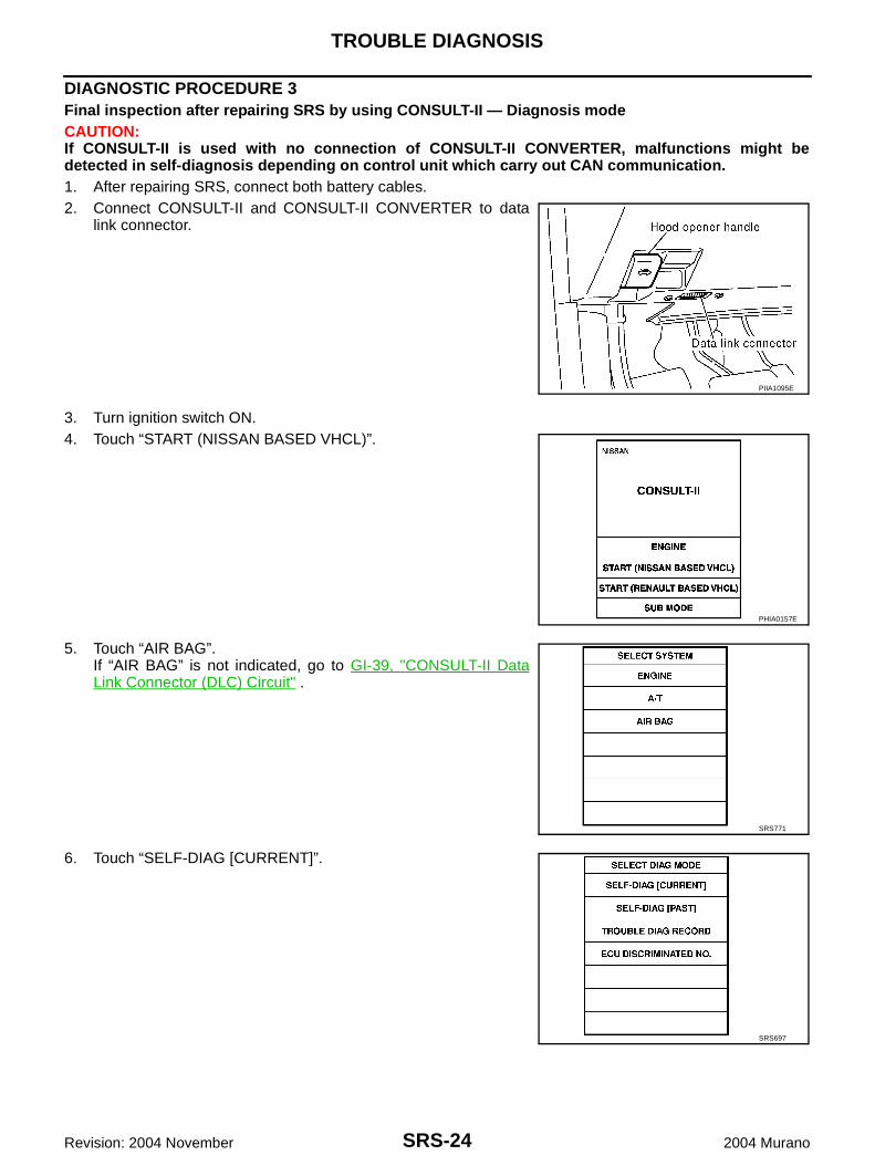
DIAGNOSTIC PROCEDURE 3Final inspection after repairing SRS by using CONSULT-II — Diagnosis modeCAUTION:If CONSULT-II is used with no connection of CONSULT-II CONVERTER, malfunctions might bedetected in self-diagnosis depending on control unit which carry out CAN communication.1. After repairing SRS, connect both battery cables.2. Connect CONSULT-II and CONSULT-II CONVERTER to data
link connector.
3. Turn ignition switch ON.4. Touch “START (NISSAN BASED VHCL)”.
5. Touch “AIR BAG”.If “AIR BAG” is not indicated, go to GI-39, "CONSULT-II DataLink Connector (DLC) Circuit" .
6. Touch “SELF-DIAG [CURRENT]”.
PIIA1095E
PHIA0157E
SRS771
SRS697
TROUBLE DIAGNOSIS
SRS-25
C
D
E
F
G
I
J
K
L
M
A
B
SRS
Revision: 2004 November 2004 Murano
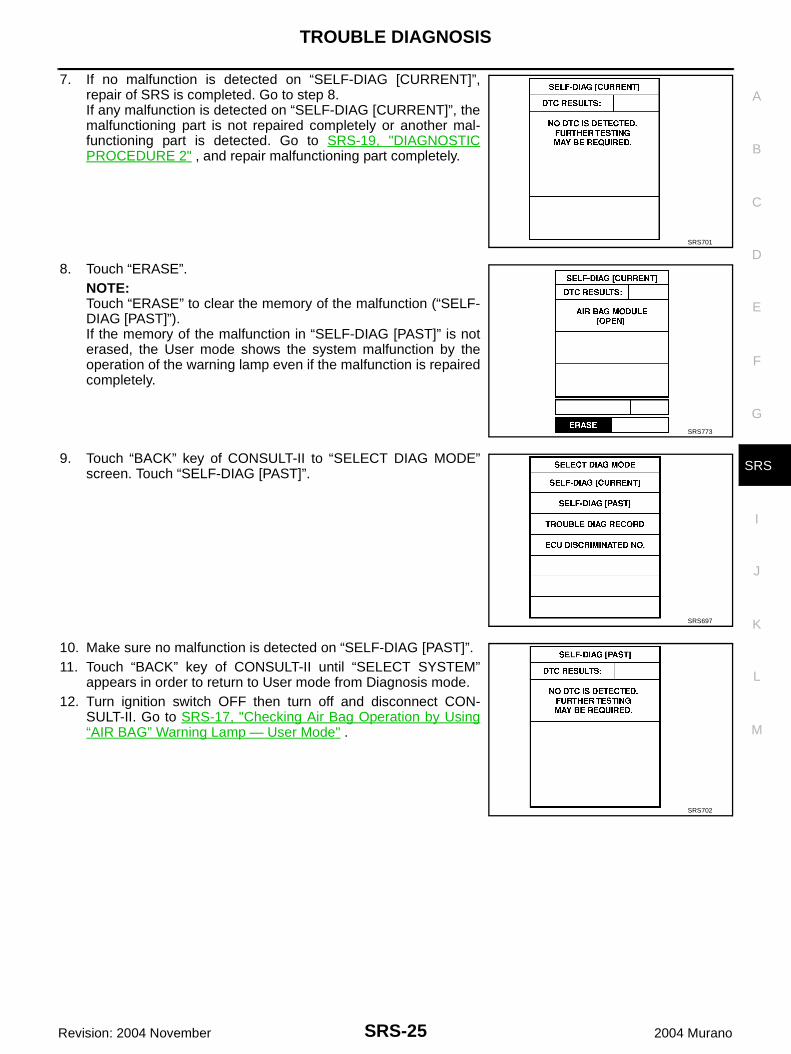
7. If no malfunction is detected on “SELF-DIAG [CURRENT]”,repair of SRS is completed. Go to step 8.If any malfunction is detected on “SELF-DIAG [CURRENT]”, themalfunctioning part is not repaired completely or another mal-functioning part is detected. Go to SRS-19, "DIAGNOSTICPROCEDURE 2" , and repair malfunctioning part completely.
8. Touch “ERASE”.NOTE:Touch “ERASE” to clear the memory of the malfunction (“SELF-DIAG [PAST]”).If the memory of the malfunction in “SELF-DIAG [PAST]” is noterased, the User mode shows the system malfunction by theoperation of the warning lamp even if the malfunction is repairedcompletely.
9. Touch “BACK” key of CONSULT-II to “SELECT DIAG MODE”screen. Touch “SELF-DIAG [PAST]”.
10. Make sure no malfunction is detected on “SELF-DIAG [PAST]”.11. Touch “BACK” key of CONSULT-II until “SELECT SYSTEM”
appears in order to return to User mode from Diagnosis mode.12. Turn ignition switch OFF then turn off and disconnect CON-
SULT-II. Go to SRS-17, "Checking Air Bag Operation by Using“AIR BAG” Warning Lamp — User Mode" .
SRS701
SRS773
SRS697
SRS702
SRS-26
TROUBLE DIAGNOSIS
Revision: 2004 November 2004 Murano
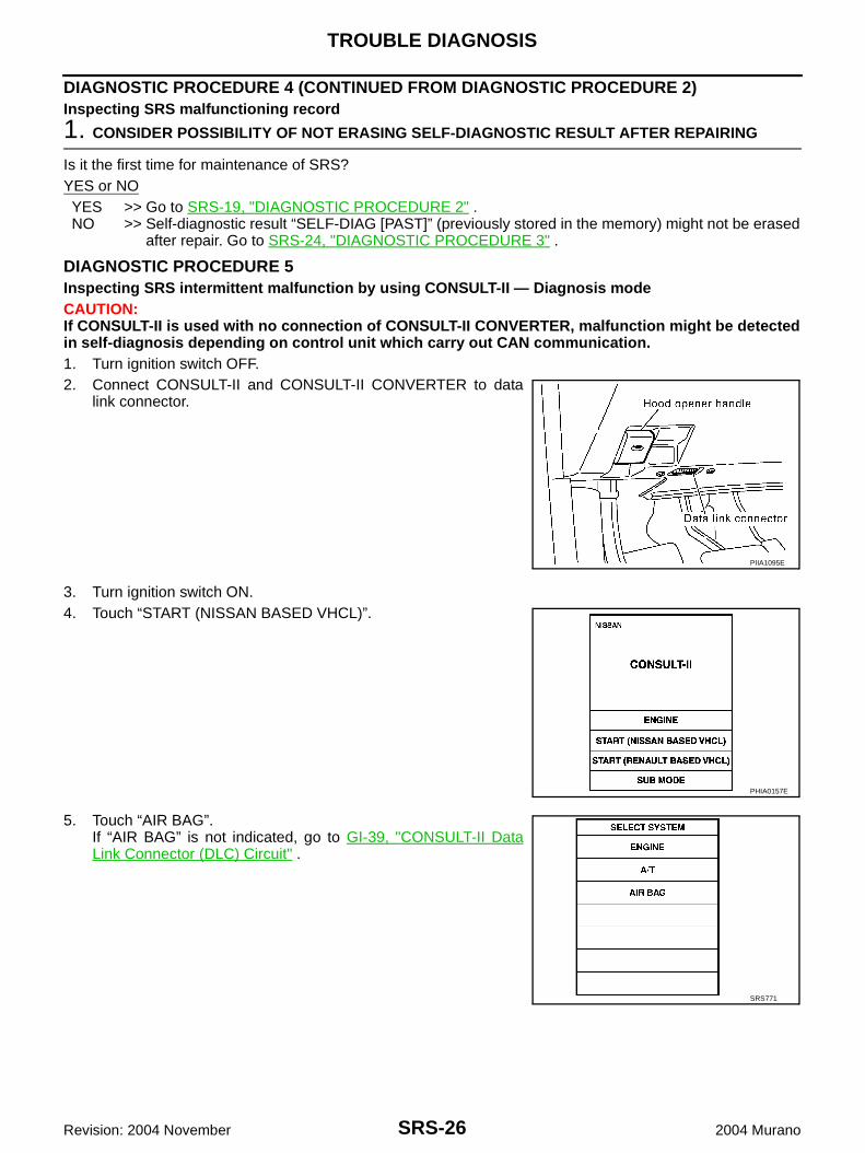
DIAGNOSTIC PROCEDURE 4 (CONTINUED FROM DIAGNOSTIC PROCEDURE 2)Inspecting SRS malfunctioning record
1. CONSIDER POSSIBILITY OF NOT ERASING SELF-DIAGNOSTIC RESULT AFTER REPAIRING
Is it the first time for maintenance of SRS?YES or NOYES >> Go to SRS-19, "DIAGNOSTIC PROCEDURE 2" .NO >> Self-diagnostic result “SELF-DIAG [PAST]” (previously stored in the memory) might not be erased
after repair. Go to SRS-24, "DIAGNOSTIC PROCEDURE 3" .
DIAGNOSTIC PROCEDURE 5Inspecting SRS intermittent malfunction by using CONSULT-II — Diagnosis modeCAUTION:If CONSULT-II is used with no connection of CONSULT-II CONVERTER, malfunction might be detectedin self-diagnosis depending on control unit which carry out CAN communication.1. Turn ignition switch OFF.2. Connect CONSULT-II and CONSULT-II CONVERTER to data
link connector.
3. Turn ignition switch ON.4. Touch “START (NISSAN BASED VHCL)”.
5. Touch “AIR BAG”.If “AIR BAG” is not indicated, go to GI-39, "CONSULT-II DataLink Connector (DLC) Circuit" .
PIIA1095E
PHIA0157E
SRS771
TROUBLE DIAGNOSIS
SRS-27
C
D
E
F
G
I
J
K
L
M
A
B
SRS
Revision: 2004 November 2004 Murano
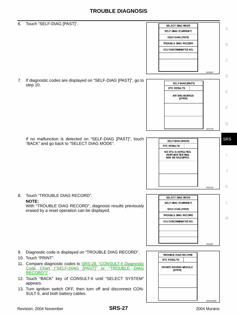
6. Touch “SELF-DIAG [PAST]”.
7. If diagnostic codes are displayed on “SELF-DIAG [PAST]”, go tostep 10.
If no malfunction is detected on “SELF-DIAG [PAST]”, touch“BACK” and go back to “SELECT DIAG MODE”.
8. Touch “TROUBLE DIAG RECORD”.NOTE:With “TROUBLE DIAG RECORD”, diagnosis results previouslyerased by a reset operation can be displayed.
9. Diagnostic code is displayed on “TROUBLE DIAG RECORD”.10. Touch “PRINT”.11. Compare diagnostic codes to SRS-28, "CONSULT-II Diagnostic
Code Chart (“SELF-DIAG [PAST]” or “TROUBLE DIAGRECORD”)" .
12. Touch “BACK” key of CONSULT-II until “SELECT SYSTEM”appears.
13. Turn ignition switch OFF, then turn off and disconnect CON-SULT-II, and both battery cables.
SRS697
SRS700
SRS702
SRS697
SHIA0182E
SRS-28
TROUBLE DIAGNOSIS
Revision: 2004 November 2004 Murano
14. Repair the system as outlined by the “Repair order” in “Intermittent Malfunction Diagnostic Code Chart”,that corresponds to the self-diagnostic result. For replacement procedure of component parts, refer to theRemoval and Installation procedure for the appropriate component.
15. Go to SRS-24, "DIAGNOSTIC PROCEDURE 3" , for final checking.
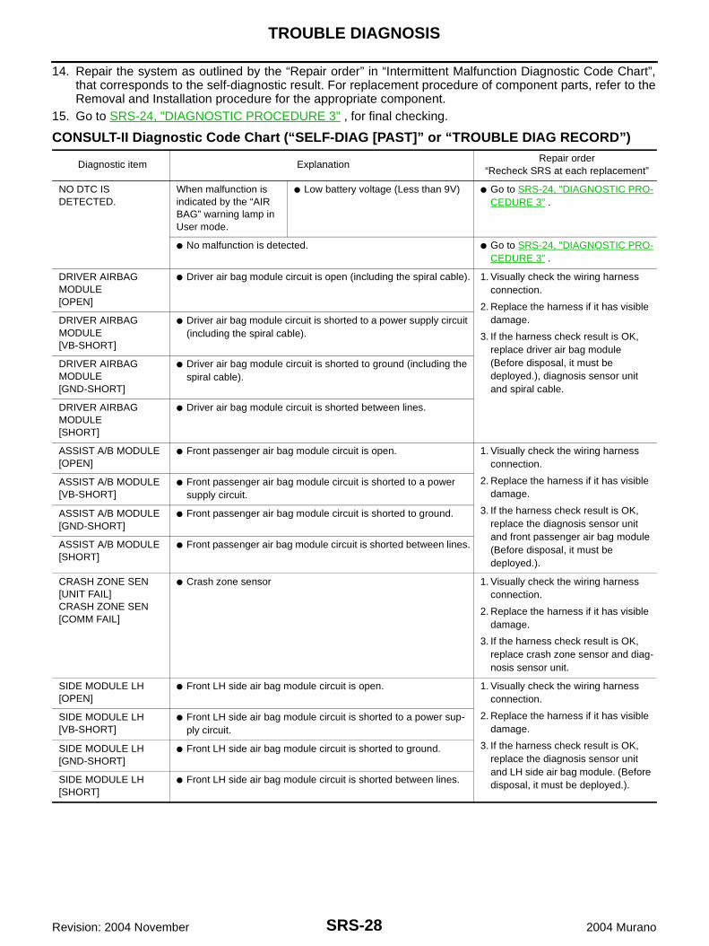
CONSULT-II Diagnostic Code Chart (“SELF-DIAG [PAST]” or “TROUBLE DIAG RECORD”)
Diagnostic item ExplanationRepair order
“Recheck SRS at each replacement”
NO DTC IS DETECTED.
When malfunction is indicated by the “AIR BAG” warning lamp in User mode.
● Low battery voltage (Less than 9V) ● Go to SRS-24, "DIAGNOSTIC PRO-CEDURE 3" .
● No malfunction is detected. ● Go to SRS-24, "DIAGNOSTIC PRO-CEDURE 3" .
DRIVER AIRBAG MODULE[OPEN]
● Driver air bag module circuit is open (including the spiral cable). 1. Visually check the wiring harness connection.
2. Replace the harness if it has visible damage.
3. If the harness check result is OK, replace driver air bag module (Before disposal, it must be deployed.), diagnosis sensor unit and spiral cable.
DRIVER AIRBAG MODULE[VB-SHORT]
● Driver air bag module circuit is shorted to a power supply circuit (including the spiral cable).
DRIVER AIRBAG MODULE[GND-SHORT]
● Driver air bag module circuit is shorted to ground (including the spiral cable).
DRIVER AIRBAG MODULE[SHORT]
● Driver air bag module circuit is shorted between lines.
ASSIST A/B MODULE[OPEN]
● Front passenger air bag module circuit is open. 1. Visually check the wiring harness connection.
2. Replace the harness if it has visible damage.
3. If the harness check result is OK, replace the diagnosis sensor unit and front passenger air bag module (Before disposal, it must be deployed.).
ASSIST A/B MODULE[VB-SHORT]
● Front passenger air bag module circuit is shorted to a power supply circuit.
ASSIST A/B MODULE[GND-SHORT]
● Front passenger air bag module circuit is shorted to ground.
ASSIST A/B MODULE[SHORT]
● Front passenger air bag module circuit is shorted between lines.
CRASH ZONE SEN[UNIT FAIL]CRASH ZONE SEN[COMM FAIL]
● Crash zone sensor 1. Visually check the wiring harness connection.
2. Replace the harness if it has visible damage.
3. If the harness check result is OK, replace crash zone sensor and diag-nosis sensor unit.
SIDE MODULE LH[OPEN]
● Front LH side air bag module circuit is open. 1. Visually check the wiring harness connection.
2. Replace the harness if it has visible damage.
3. If the harness check result is OK, replace the diagnosis sensor unit and LH side air bag module. (Before disposal, it must be deployed.).
SIDE MODULE LH[VB-SHORT]
● Front LH side air bag module circuit is shorted to a power sup-ply circuit.
SIDE MODULE LH[GND-SHORT]
● Front LH side air bag module circuit is shorted to ground.
SIDE MODULE LH[SHORT]
● Front LH side air bag module circuit is shorted between lines.
TROUBLE DIAGNOSIS
SRS-29
C
D
E
F
G
I
J
K
L
M
A
B
SRS
Revision: 2004 November 2004 Murano
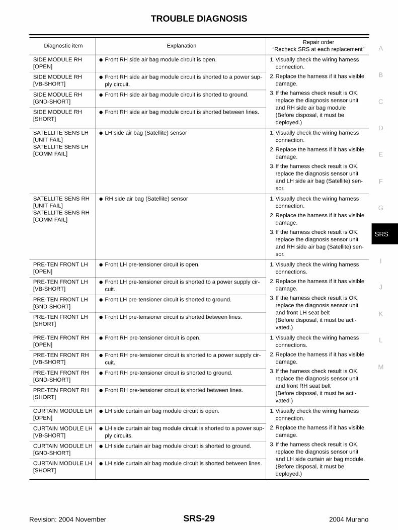
SIDE MODULE RH[OPEN]
● Front RH side air bag module circuit is open. 1. Visually check the wiring harness connection.
2. Replace the harness if it has visible damage.
3. If the harness check result is OK, replace the diagnosis sensor unit and RH side air bag module (Before disposal, it must be deployed.)
SIDE MODULE RH[VB-SHORT]
● Front RH side air bag module circuit is shorted to a power sup-ply circuit.
SIDE MODULE RH[GND-SHORT]
● Front RH side air bag module circuit is shorted to ground.
SIDE MODULE RH[SHORT]
● Front RH side air bag module circuit is shorted between lines.
SATELLITE SENS LH[UNIT FAIL]SATELLITE SENS LH[COMM FAIL]
● LH side air bag (Satellite) sensor 1. Visually check the wiring harness connection.
2. Replace the harness if it has visible damage.
3. If the harness check result is OK, replace the diagnosis sensor unit and LH side air bag (Satellite) sen-sor.
SATELLITE SENS RH[UNIT FAIL]SATELLITE SENS RH[COMM FAIL]
● RH side air bag (Satellite) sensor 1. Visually check the wiring harness connection.
2. Replace the harness if it has visible damage.
3. If the harness check result is OK, replace the diagnosis sensor unit and RH side air bag (Satellite) sen-sor.
PRE-TEN FRONT LH[OPEN]
● Front LH pre-tensioner circuit is open. 1. Visually check the wiring harness connections.
2. Replace the harness if it has visible damage.
3. If the harness check result is OK, replace the diagnosis sensor unit and front LH seat belt(Before disposal, it must be acti-vated.)
PRE-TEN FRONT LH[VB-SHORT]
● Front LH pre-tensioner circuit is shorted to a power supply cir-cuit.
PRE-TEN FRONT LH[GND-SHORT]
● Front LH pre-tensioner circuit is shorted to ground.
PRE-TEN FRONT LH[SHORT]
● Front LH pre-tensioner circuit is shorted between lines.
PRE-TEN FRONT RH[OPEN]
● Front RH pre-tensioner circuit is open. 1. Visually check the wiring harness connections.
2. Replace the harness if it has visible damage.
3. If the harness check result is OK, replace the diagnosis sensor unit and front RH seat belt(Before disposal, it must be acti-vated.)
PRE-TEN FRONT RH[VB-SHORT]
● Front RH pre-tensioner circuit is shorted to a power supply cir-cuit.
PRE-TEN FRONT RH[GND-SHORT]
● Front RH pre-tensioner circuit is shorted to ground.
PRE-TEN FRONT RH[SHORT]
● Front RH pre-tensioner circuit is shorted between lines.
CURTAIN MODULE LH[OPEN]
● LH side curtain air bag module circuit is open. 1. Visually check the wiring harness connection.
2. Replace the harness if it has visible damage.
3. If the harness check result is OK, replace the diagnosis sensor unit and LH side curtain air bag module.(Before disposal, it must be deployed.)
CURTAIN MODULE LH[VB-SHORT]
● LH side curtain air bag module circuit is shorted to a power sup-ply circuits.
CURTAIN MODULE LH[GND-SHORT]
● LH side curtain air bag module circuit is shorted to ground.
CURTAIN MODULE LH [SHORT]
● LH side curtain air bag module circuit is shorted between lines.
Diagnostic item ExplanationRepair order
“Recheck SRS at each replacement”
SRS-30
TROUBLE DIAGNOSIS
Revision: 2004 November 2004 Murano
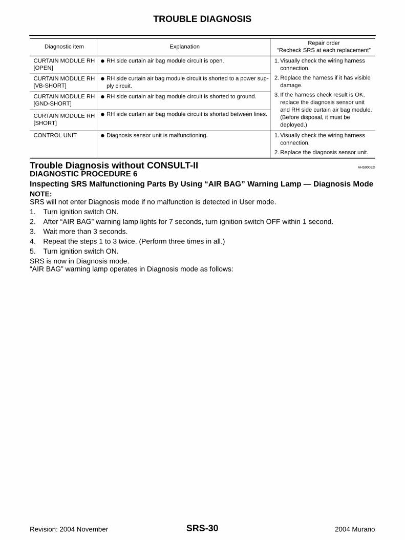
Trouble Diagnosis without CONSULT-II AHS000ED
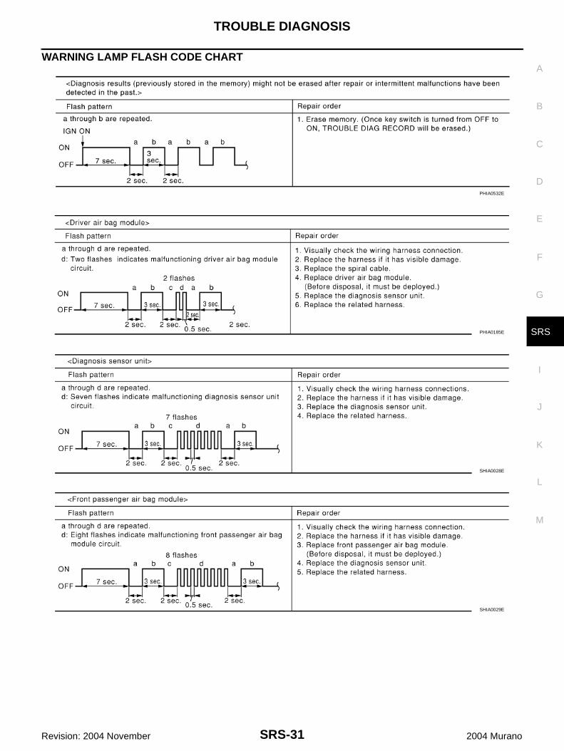
DIAGNOSTIC PROCEDURE 6Inspecting SRS Malfunctioning Parts By Using “AIR BAG” Warning Lamp — Diagnosis ModeNOTE:SRS will not enter Diagnosis mode if no malfunction is detected in User mode.1. Turn ignition switch ON.2. After “AIR BAG” warning lamp lights for 7 seconds, turn ignition switch OFF within 1 second.3. Wait more than 3 seconds.4. Repeat the steps 1 to 3 twice. (Perform three times in all.)5. Turn ignition switch ON.SRS is now in Diagnosis mode.“AIR BAG” warning lamp operates in Diagnosis mode as follows:
CURTAIN MODULE RH[OPEN]
● RH side curtain air bag module circuit is open. 1. Visually check the wiring harness connection.
2. Replace the harness if it has visible damage.
3. If the harness check result is OK, replace the diagnosis sensor unit and RH side curtain air bag module.(Before disposal, it must be deployed.)
CURTAIN MODULE RH[VB-SHORT]
● RH side curtain air bag module circuit is shorted to a power sup-ply circuit.
CURTAIN MODULE RH[GND-SHORT]
● RH side curtain air bag module circuit is shorted to ground.
CURTAIN MODULE RH[SHORT]
● RH side curtain air bag module circuit is shorted between lines.
CONTROL UNIT ● Diagnosis sensor unit is malfunctioning. 1. Visually check the wiring harness connection.
2. Replace the diagnosis sensor unit.
Diagnostic item ExplanationRepair order
“Recheck SRS at each replacement”
TROUBLE DIAGNOSIS
SRS-31
C
D
E
F
G
I
J
K
L
M
A
B
SRS
Revision: 2004 November 2004 Murano
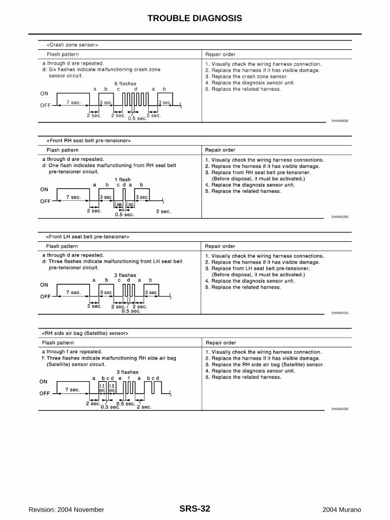
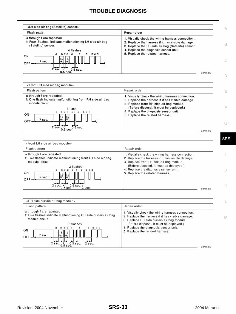
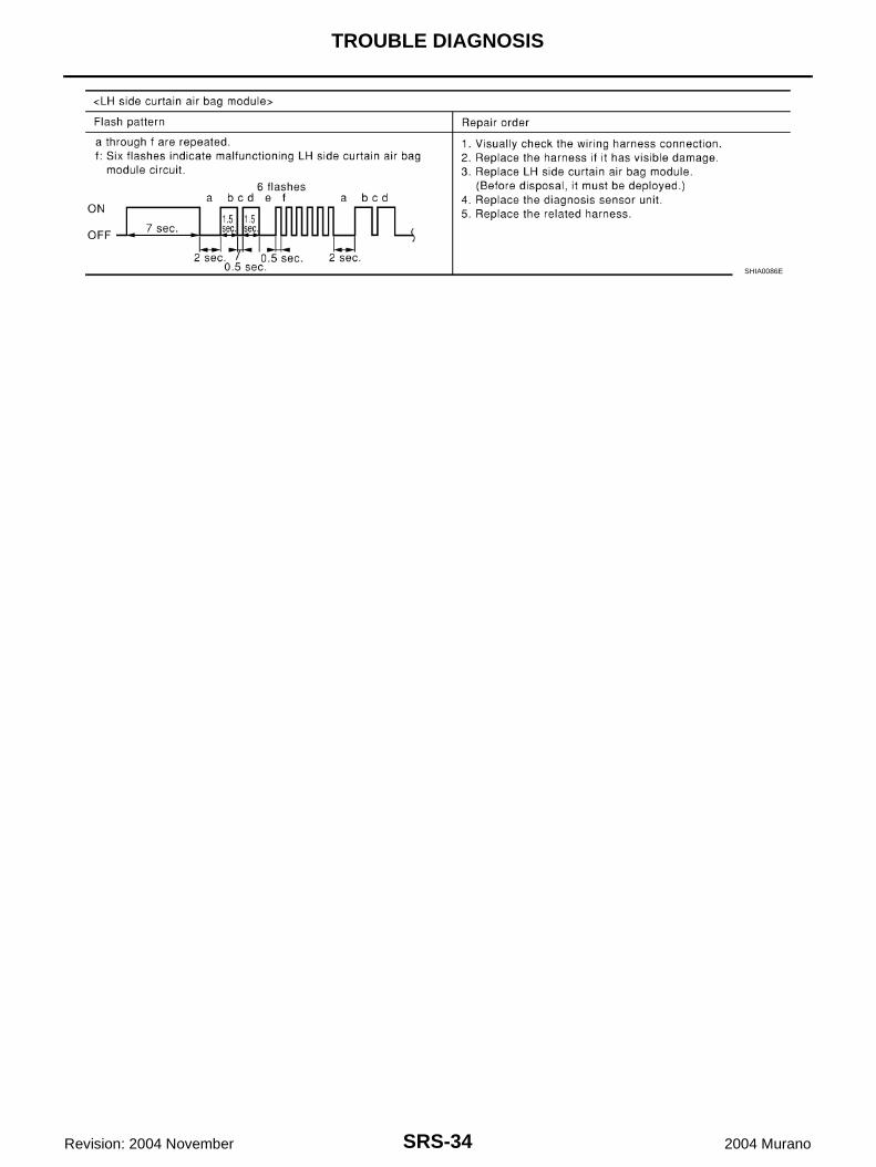
WARNING LAMP FLASH CODE CHART
PHIA0532E
PHIA0185E
SHIA0028E
SHIA0029E
SRS-32
TROUBLE DIAGNOSIS
Revision: 2004 November 2004 Murano
SHIA0083E
SHIA0030E
SHIA0031E
SHIA0032E
TROUBLE DIAGNOSIS
SRS-33
C
D
E
F
G
I
J
K
L
M
A
B
SRS
Revision: 2004 November 2004 Murano
SHIA0033E
SHIA0034E
SHIA0035E
SHIA0084E
SRS-34
TROUBLE DIAGNOSIS
Revision: 2004 November 2004 Murano
SHIA0086E
TROUBLE DIAGNOSIS
SRS-35
C
D
E
F
G
I
J
K
L
M
A
B
SRS
Revision: 2004 November 2004 Murano
Trouble Diagnosis: “AIR BAG” Warning Lamp Does Not Turn Off AHS000EE
DIAGNOSTIC PROCEDURE 7
1. CHECK THE DEPLOYMENT OF AIR BAG MODULE
Is air bag module deployed?YES or NOYES >> Refer to SRS-58, "COLLISION DIAGNOSIS" .NO >> GO TO 2.
2. CHECK THE AIR BAG FUSE
Check 10A fuse [No.13, located in fuse block (J/B)].Refer to PG-3, "POWER SUPPLY ROUTING CIRCUIT" .OK or NGOK >> GO TO 4.NG >> GO TO 3.
3. CHECK AIR BAG FUSE AGAIN
Replace “AIR BAG” fuse and turn ignition switch ON.Does the “AIR BAG” fuse blow again?YES >> Repair main harness.NO >> INSPECTION END
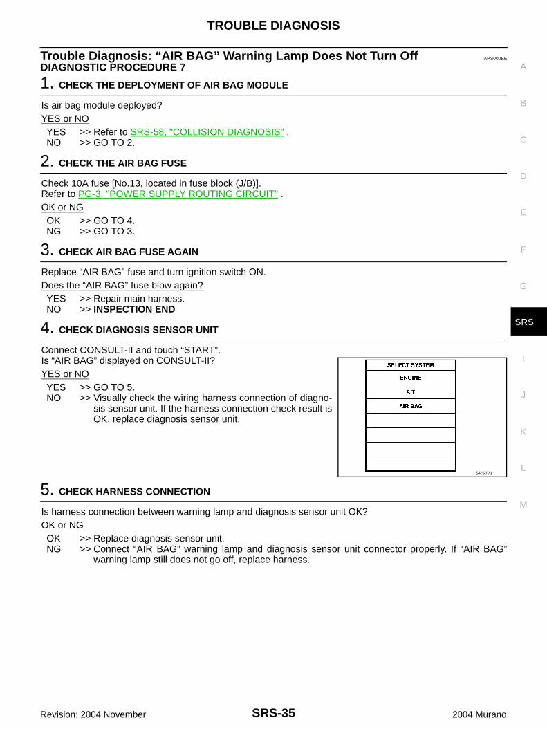
4. CHECK DIAGNOSIS SENSOR UNIT
Connect CONSULT-II and touch “START”.Is “AIR BAG” displayed on CONSULT-II?YES or NOYES >> GO TO 5.NO >> Visually check the wiring harness connection of diagno-
sis sensor unit. If the harness connection check result isOK, replace diagnosis sensor unit.
5. CHECK HARNESS CONNECTION
Is harness connection between warning lamp and diagnosis sensor unit OK?OK or NGOK >> Replace diagnosis sensor unit.NG >> Connect “AIR BAG” warning lamp and diagnosis sensor unit connector properly. If “AIR BAG”
warning lamp still does not go off, replace harness.
SRS771
SRS-36
TROUBLE DIAGNOSIS
Revision: 2004 November 2004 Murano
Trouble Diagnosis: “AIR BAG” Warning Lamp Does Not Turn On AHS000EF
DIAGNOSTIC PROCEDURE 8
1. CHECK METER FUSE
Check 10A fuse [No.14, located in fuse block (J/B)].Refer to PG-3, "POWER SUPPLY ROUTING CIRCUIT" .OK or NGOK >> GO TO 3.NG >> GO TO 2.
2. CHECK METER FUSE AGAIN
Replace 10A fuse [No.14, located in fuse block (J/B)] and turn ignition switch ON.Does the meter fuse blow again?YES >> Repair the related harness.NO >> INSPECTION END
3. CHECK HARNESS CONNECTION BETWEEN DIAGNOSIS SENSOR UNIT AND COMBINATION METER
Disconnect diagnosis sensor unit connector and turn ignition switch ON.Does “AIR BAG” warning lamp turn on?YES or NOYES >> Replace diagnosis sensor unit.NO >> Replace combination meter assembly.
DRIVER AIR BAG MODULE
SRS-37
C
D
E
F
G
I
J
K
L
M
A
B
SRS
Revision: 2004 November 2004 Murano
DRIVER AIR BAG MODULE PFP:K8510
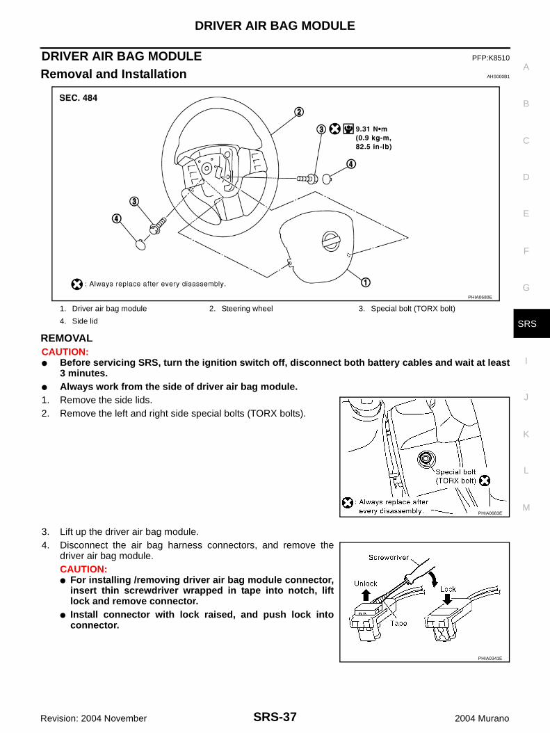
Removal and Installation AHS000B1
REMOVALCAUTION:● Before servicing SRS, turn the ignition switch off, disconnect both battery cables and wait at least
3 minutes.● Always work from the side of driver air bag module.1. Remove the side lids.2. Remove the left and right side special bolts (TORX bolts).
3. Lift up the driver air bag module.4. Disconnect the air bag harness connectors, and remove the
driver air bag module.CAUTION:● For installing /removing driver air bag module connector,
insert thin screwdriver wrapped in tape into notch, liftlock and remove connector.
● Install connector with lock raised, and push lock intoconnector.
1. Driver air bag module 2. Steering wheel 3. Special bolt (TORX bolt)
4. Side lid
PHIA0680E
PHIA0683E
PHIA0341E
SRS-38
DRIVER AIR BAG MODULE
Revision: 2004 November 2004 Murano
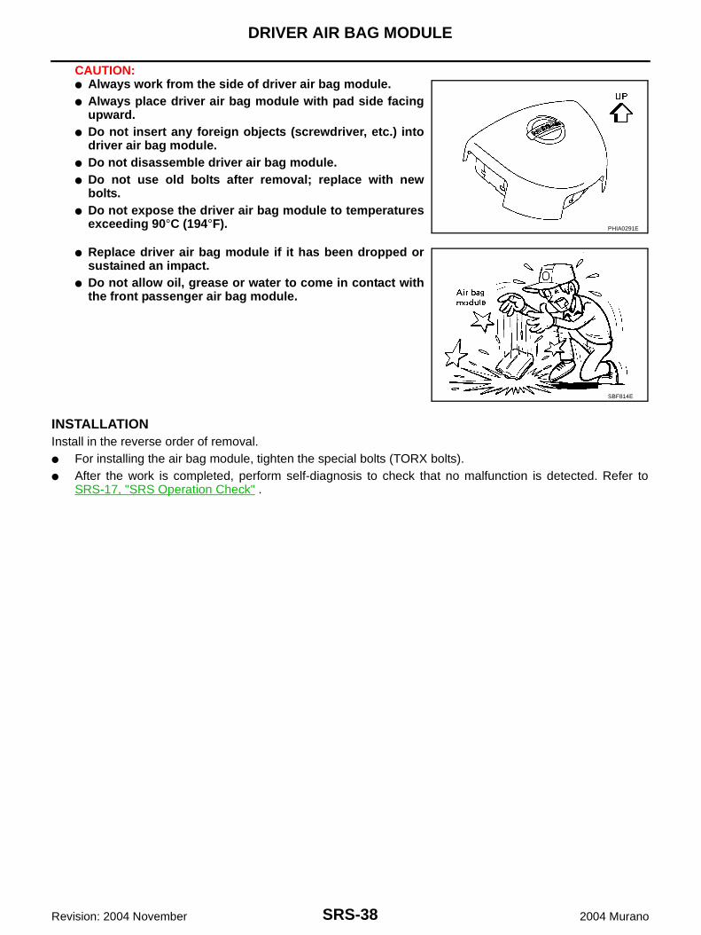
CAUTION:● Always work from the side of driver air bag module.● Always place driver air bag module with pad side facing
upward.● Do not insert any foreign objects (screwdriver, etc.) into
driver air bag module.● Do not disassemble driver air bag module.● Do not use old bolts after removal; replace with new
bolts.● Do not expose the driver air bag module to temperatures
exceeding 90°C (194°F).
● Replace driver air bag module if it has been dropped orsustained an impact.
● Do not allow oil, grease or water to come in contact withthe front passenger air bag module.
INSTALLATIONInstall in the reverse order of removal.● For installing the air bag module, tighten the special bolts (TORX bolts).● After the work is completed, perform self-diagnosis to check that no malfunction is detected. Refer to
SRS-17, "SRS Operation Check" .
PHIA0291E
SBF814E
SPIRAL CABLE
SRS-39
C
D
E
F
G
I
J
K
L
M
A
B
SRS
Revision: 2004 November 2004 Murano
SPIRAL CABLE PFP:25554
Removal and Installation AHS000B2
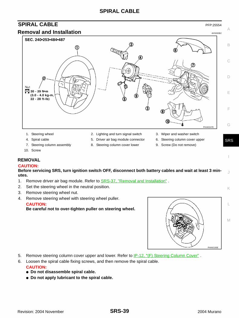
REMOVALCAUTION:Before servicing SRS, turn ignition switch OFF, disconnect both battery cables and wait at least 3 min-utes.1. Remove driver air bag module. Refer to SRS-37, "Removal and Installation" .2. Set the steering wheel in the neutral position.3. Remove steering wheel nut.4. Remove steering wheel with steering wheel puller.
CAUTION:Be careful not to over-tighten puller on steering wheel.
5. Remove steering column cover upper and lower. Refer to IP-12, "(F) Steering Column Cover" .6. Loosen the spiral cable fixing screws, and then remove the spiral cable.
CAUTION:● Do not disassemble spiral cable.● Do not apply lubricant to the spiral cable.
PHIA0247E
1. Steering wheel 2. Lighting and turn signal switch 3. Wiper and washer switch
4. Spiral cable 5. Driver air bag module connector 6. Steering column cover upper
7. Steering column assembly 8. Steering column cover lower 9. Screw (Do not remove)
10. Screw
PHIA0100E
SRS-40
SPIRAL CABLE
Revision: 2004 November 2004 Murano
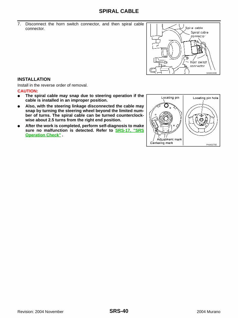
7. Disconnect the horn switch connector, and then spiral cableconnector.
INSTALLATIONInstall in the reverse order of removal.CAUTION:● The spiral cable may snap due to steering operation if the
cable is installed in an improper position.● Also, with the steering linkage disconnected the cable may
snap by turning the steering wheel beyond the limited num-ber of turns. The spiral cable can be turned counterclock-wise about 2.5 turns from the right end position.
● After the work is completed, perform self-diagnosis to makesure no malfunction is detected. Refer to SRS-17, "SRSOperation Check" .
SHIA0193E
PHIA0275E
FRONT PASSENGER AIR BAG MODULE
SRS-41
C
D
E
F
G
I
J
K
L
M
A
B
SRS
Revision: 2004 November 2004 Murano
FRONT PASSENGER AIR BAG MODULE PFP:K8515
Removal and Installation AHS000B3
REMOVALCAUTION:● Before servicing SRS, turn ignition switch OFF, disconnect both battery cables and wait at least 3
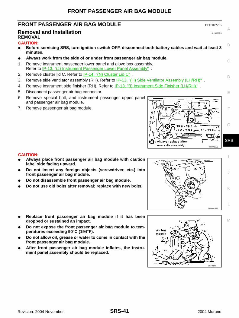
minutes.● Always work from the side of or under front passenger air bag module.1. Remove instrument passenger lower panel and glove box assembly.
Refer to IP-13, "(J) Instrument Passenger Lower Panel Assembly" .2. Remove cluster lid C. Refer to IP-14, "(N) Cluster Lid C" .3. Remove side ventilator assembly (RH). Refer to IP-13, "(H) Side Ventilator Assembly (LH/RH)" .4. Remove instrument side finisher (RH). Refer to IP-13, "(I) Instrument Side Finisher (LH/RH)" .5. Disconnect passenger air bag connector.6. Remove special bolt, and instrument passenger upper panel
and passenger air bag module.7. Remove passenger air bag module.
CAUTION:● Always place front passenger air bag module with caution
label side facing upward.● Do not insert any foreign objects (screwdriver, etc.) into
front passenger air bag module.● Do not disassemble front passenger air bag module.● Do not use old bolts after removal; replace with new bolts.
● Replace front passenger air bag module if it has beendropped or sustained an impact.
● Do not expose the front passenger air bag module to tem-peratures exceeding 90°C (194°F).
● Do not allow oil, grease or water to come in contact with thefront passenger air bag module.
● After front passenger air bag module inflates, the instru-ment panel assembly should be replaced.
PHIA0250E
PHIA0167E
SBF814E
SRS-42
FRONT PASSENGER AIR BAG MODULE
Revision: 2004 November 2004 Murano
INSTALLATIONInstall in the reverse order of removal.CAUTION:● Always work from the side of or under front passenger air bag module.● After the work is completed, perform self-diagnosis to make sure no malfunction is detected.
Refer to SRS-17, "SRS Operation Check" .
FRONT SIDE AIR BAG MODULE
SRS-43
C
D
E
F
G
I
J
K
L
M
A
B
SRS
Revision: 2004 November 2004 Murano
FRONT SIDE AIR BAG MODULE PFP:K8EH0
Removal and Installation AHS000B4
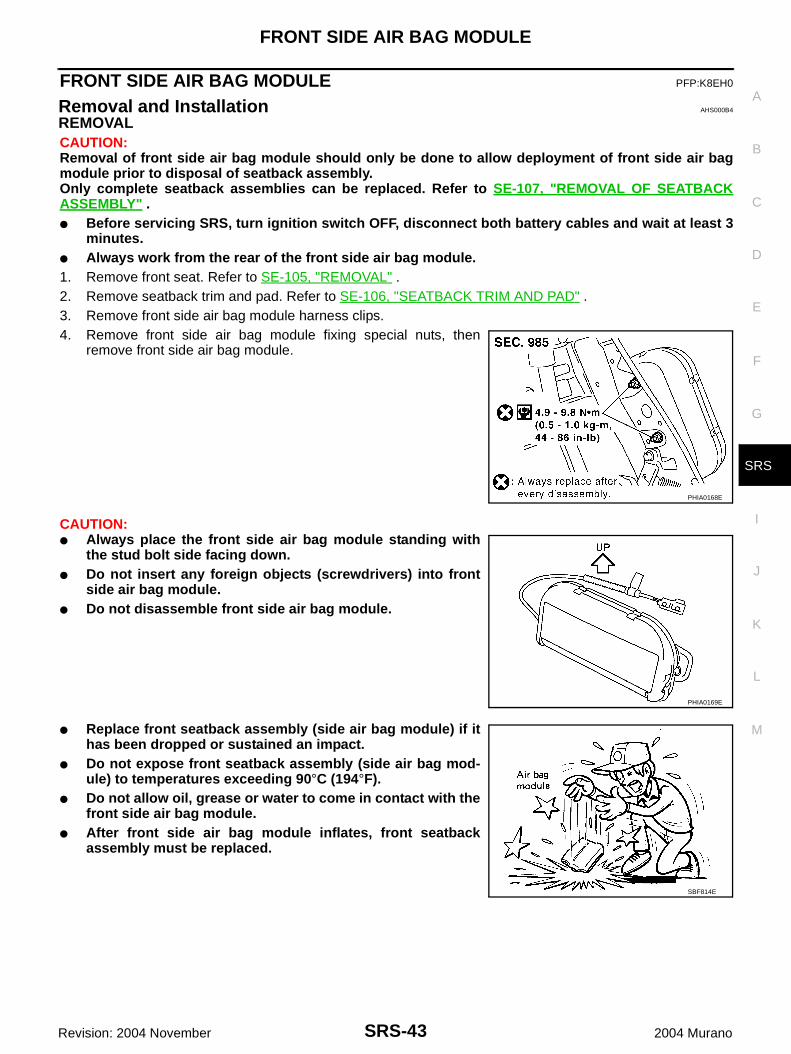
REMOVALCAUTION:Removal of front side air bag module should only be done to allow deployment of front side air bagmodule prior to disposal of seatback assembly.Only complete seatback assemblies can be replaced. Refer to SE-107, "REMOVAL OF SEATBACKASSEMBLY" .● Before servicing SRS, turn ignition switch OFF, disconnect both battery cables and wait at least 3
minutes.● Always work from the rear of the front side air bag module.1. Remove front seat. Refer to SE-105, "REMOVAL" .2. Remove seatback trim and pad. Refer to SE-106, "SEATBACK TRIM AND PAD" .3. Remove front side air bag module harness clips.4. Remove front side air bag module fixing special nuts, then
remove front side air bag module.
CAUTION:● Always place the front side air bag module standing with
the stud bolt side facing down.● Do not insert any foreign objects (screwdrivers) into front
side air bag module.● Do not disassemble front side air bag module.
● Replace front seatback assembly (side air bag module) if ithas been dropped or sustained an impact.
● Do not expose front seatback assembly (side air bag mod-ule) to temperatures exceeding 90°C (194°F).
● Do not allow oil, grease or water to come in contact with thefront side air bag module.
● After front side air bag module inflates, front seatbackassembly must be replaced.
PHIA0168E
PHIA0169E
SBF814E
SRS-44
FRONT SIDE AIR BAG MODULE
Revision: 2004 November 2004 Murano
INSTALLATIONInstall in the reverse order of removal.CAUTION:● Always work from the rear of the front side air bag module.● After the work is completed, perform self-diagnosis to make sure that no malfunction is detected.
Refer to SRS-17, "SRS Operation Check" .
SIDE CURTAIN AIR BAG MODULE
SRS-45
C
D
E
F
G
I
J
K
L
M
A
B
SRS
Revision: 2004 November 2004 Murano
SIDE CURTAIN AIR BAG MODULE PFP:985P0
Removal and Installation AHS000B5
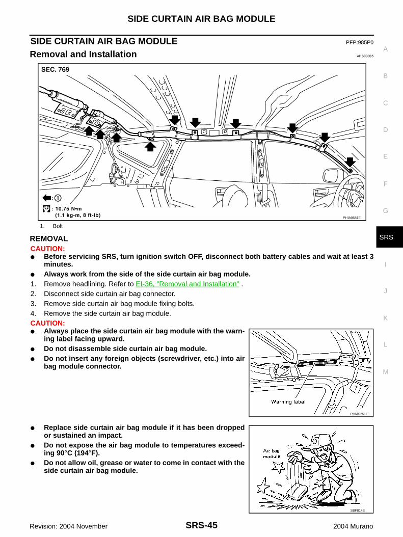
REMOVALCAUTION:● Before servicing SRS, turn ignition switch OFF, disconnect both battery cables and wait at least 3
minutes.● Always work from the side of the side curtain air bag module.1. Remove headlining. Refer to EI-36, "Removal and Installation" .2. Disconnect side curtain air bag connector.3. Remove side curtain air bag module fixing bolts.4. Remove the side curtain air bag module.CAUTION:● Always place the side curtain air bag module with the warn-
ing label facing upward.● Do not disassemble side curtain air bag module.● Do not insert any foreign objects (screwdriver, etc.) into air
bag module connector.
● Replace side curtain air bag module if it has been droppedor sustained an impact.
● Do not expose the air bag module to temperatures exceed-ing 90°C (194°F).
● Do not allow oil, grease or water to come in contact with theside curtain air bag module.
1. Bolt
PHIA0681E
PHIA0251E
SBF814E
SRS-46
SIDE CURTAIN AIR BAG MODULE
Revision: 2004 November 2004 Murano
INSTALLATIONInstall in the reverse order of removal.CAUTION:● Always work from the side of the side curtain air bag module.● After replacement of side curtain air bag module, perform self-diagnosis to make sure no malfunc-
tion is detected. Refer to SRS-17, "SRS Operation Check" .
CRASH ZONE SENSOR
SRS-47
C
D
E
F
G
I
J
K
L
M
A
B
SRS
Revision: 2004 November 2004 Murano
CRASH ZONE SENSOR PFP:98531
Removal and Installation AHS000B6
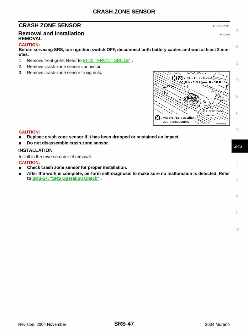
REMOVALCAUTION:Before servicing SRS, turn ignition switch OFF, disconnect both battery cables and wait at least 3 min-utes.1. Remove front grille. Refer to EI-20, "FRONT GRILLE" .2. Remove crash zone sensor connector.3. Remove crash zone sensor fixing nuts.
CAUTION:● Replace crash zone sensor if it has been dropped or sustained an impact.● Do not disassemble crash zone sensor.
INSTALLATIONInstall in the reverse order of removal.CAUTION:● Check crash zone sensor for proper installation.● After the work is complete, perform self-diagnosis to make sure no malfunction is detected. Refer
to SRS-17, "SRS Operation Check" .
PHIA0259E
SRS-48
SIDE AIR BAG (SATELLITE) SENSOR
Revision: 2004 November 2004 Murano
SIDE AIR BAG (SATELLITE) SENSOR PFP:98830
Removal and Installation AHS000B7
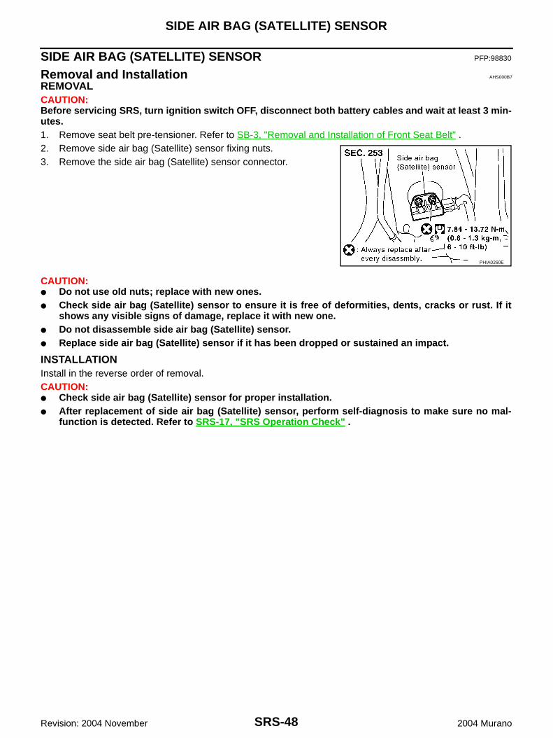
REMOVALCAUTION:Before servicing SRS, turn ignition switch OFF, disconnect both battery cables and wait at least 3 min-utes.1. Remove seat belt pre-tensioner. Refer to SB-3, "Removal and Installation of Front Seat Belt" .2. Remove side air bag (Satellite) sensor fixing nuts.3. Remove the side air bag (Satellite) sensor connector.
CAUTION:● Do not use old nuts; replace with new ones.● Check side air bag (Satellite) sensor to ensure it is free of deformities, dents, cracks or rust. If it
shows any visible signs of damage, replace it with new one.● Do not disassemble side air bag (Satellite) sensor.● Replace side air bag (Satellite) sensor if it has been dropped or sustained an impact.
INSTALLATIONInstall in the reverse order of removal.CAUTION:● Check side air bag (Satellite) sensor for proper installation.● After replacement of side air bag (Satellite) sensor, perform self-diagnosis to make sure no mal-
function is detected. Refer to SRS-17, "SRS Operation Check" .
PHIA0260E
FRONT SEAT BELT PRE-TENSIONER
SRS-49
C
D
E
F
G
I
J
K
L
M
A
B
SRS
Revision: 2004 November 2004 Murano
FRONT SEAT BELT PRE-TENSIONER PFP:86884
Removal and Installation AHS000B8
For removal and installation procedures, refer to SB-3, "Removal and Installation of Front Seat Belt" .
SRS-50
DIAGNOSIS SENSOR UNIT
Revision: 2004 November 2004 Murano
DIAGNOSIS SENSOR UNIT PFP:28556
Removal and Installation AHS000B9
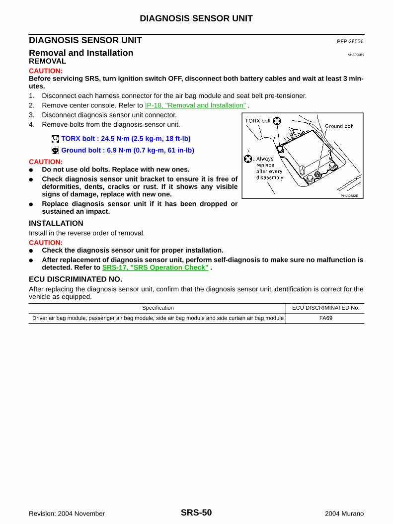
REMOVALCAUTION:Before servicing SRS, turn ignition switch OFF, disconnect both battery cables and wait at least 3 min-utes.1. Disconnect each harness connector for the air bag module and seat belt pre-tensioner.2. Remove center console. Refer to IP-18, "Removal and Installation" .3. Disconnect diagnosis sensor unit connector.4. Remove bolts from the diagnosis sensor unit.
CAUTION:● Do not use old bolts. Replace with new ones.● Check diagnosis sensor unit bracket to ensure it is free of
deformities, dents, cracks or rust. If it shows any visiblesigns of damage, replace with new one.
● Replace diagnosis sensor unit if it has been dropped orsustained an impact.
INSTALLATIONInstall in the reverse order of removal.CAUTION:● Check the diagnosis sensor unit for proper installation.● After replacement of diagnosis sensor unit, perform self-diagnosis to make sure no malfunction is
detected. Refer to SRS-17, "SRS Operation Check" .
ECU DISCRIMINATED NO.After replacing the diagnosis sensor unit, confirm that the diagnosis sensor unit identification is correct for thevehicle as equipped.
TORX bolt : 24.5 N·m (2.5 kg-m, 18 ft-lb)
Ground bolt : 6.9 N·m (0.7 kg-m, 61 in-lb)
PHIA0682E
Specification ECU DISCRIMINATED No.
Driver air bag module, passenger air bag module, side air bag module and side curtain air bag module FA69
DISPOSAL OF AIR BAG MODULE AND SEAT BELT PRE-TENSIONER
SRS-51
C
D
E
F
G
I
J
K
L
M
A
B
SRS
Revision: 2004 November 2004 Murano
DISPOSAL OF AIR BAG MODULE AND SEAT BELT PRE-TENSIONER PFP:00014
Caution for Air Bag Module and Seat Belt Pre-Tensioner AHS000BA
● Before disposing of air bag module and seat belt pre-tensioner, or vehicles equipped with such systems,deploy the systems. If such systems have already been deployed due to an accident, dispose of them asindicated in SRS-51, "DISPOSAL OF AIR BAG MODULE AND SEAT BELT PRE-TENSIONER" .
● When deploying the air bag module and seat belt pre-tensioner, always use the Special Service Tool;Deployment tool [KV99106400 (J38381)].
● When deploying the air bag module and seat belt pre-tensioner, stand at least 5 m (16 ft) away from thedeployment component.
● When deploying air bag module and seat belt pre-tensioner, a fairly loud noise is made, followed bysmoke being released. The smoke is not poisonous, however, be careful not to inhale smoke since it irri-tates the throat and can cause choking.
● Always activate one air bag module at a time.● Due to heat, leave air bag module unattended for more than 30 minutes after deployment. Also leave seat
belt pre-tensioner unattended for more than 10 minutes after deployment.● Be sure to wear gloves when handling a deployed air bag module and seat belt pre-tensioner.● Never apply water to the deployed air bag module and seat belt pre-tensioner.● Wash your hands clean after finishing work.● Place the vehicle outdoors with an open space of at least 6 m (20 ft) on all sides when deploying air bag
module and seat belt pre-tensioner while mounted in vehicle.● Use a voltmeter to make sure the vehicle battery is fully charged.● Do not dispose of the air bag module and seat belt pre-tensioner undeployed.
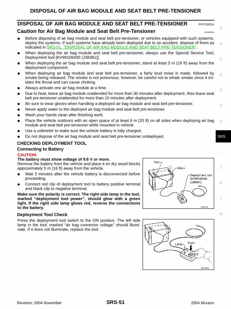
CHECKING DEPLOYMENT TOOLConnecting to BatteryCAUTION:The battery must show voltage of 9.6 V or more.Remove the battery from the vehicle and place it on dry wood blocksapproximately 5 m (16 ft) away from the vehicle.● Wait 3 minutes after the vehicle battery is disconnected before
proceeding.● Connect red clip of deployment tool to battery positive terminal
and black clip to negative terminal.Make sure the polarity is correct. The right side lamp in the tool,marked “deployment tool power”, should glow with a greenlight. If the right side lamp glows red, reverse the connectionsto the battery.
Deployment Tool CheckPress the deployment tool switch to the ON position. The left sidelamp in the tool, marked “air bag connector voltage” should illumi-nate. If it does not illuminate, replace the tool.
SRS019
SBF266H
SRS-52
DISPOSAL OF AIR BAG MODULE AND SEAT BELT PRE-TENSIONER
Revision: 2004 November 2004 Murano
Air Bag Deployment Tool Lamp Illumination Chart (Battery Connected)
*: If this lamp glows red, the tool is connected to the battery incorrectly. Reverse the connections and make sure the lamp glows green.
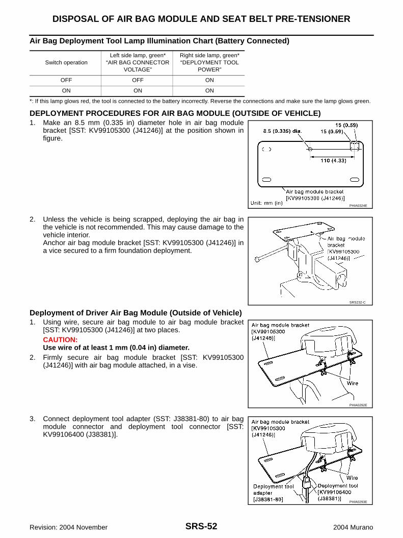
DEPLOYMENT PROCEDURES FOR AIR BAG MODULE (OUTSIDE OF VEHICLE)1. Make an 8.5 mm (0.335 in) diameter hole in air bag module
bracket [SST: KV99105300 (J41246)] at the position shown infigure.
2. Unless the vehicle is being scrapped, deploying the air bag inthe vehicle is not recommended. This may cause damage to thevehicle interior.Anchor air bag module bracket [SST: KV99105300 (J41246)] ina vice secured to a firm foundation deployment.
Deployment of Driver Air Bag Module (Outside of Vehicle)1. Using wire, secure air bag module to air bag module bracket
[SST: KV99105300 (J41246)] at two places.CAUTION:Use wire of at least 1 mm (0.04 in) diameter.
2. Firmly secure air bag module bracket [SST: KV99105300(J41246)] with air bag module attached, in a vise.
3. Connect deployment tool adapter (SST: J38381-80) to air bagmodule connector and deployment tool connector [SST:KV99106400 (J38381)].
Switch operationLeft side lamp, green*
“AIR BAG CONNECTOR VOLTAGE”
Right side lamp, green*“DEPLOYMENT TOOL
POWER”
OFF OFF ON
ON ON ON
PHIA0324E
SRS232-C
PHIA0292E
PHIA0293E
DISPOSAL OF AIR BAG MODULE AND SEAT BELT PRE-TENSIONER
SRS-53
C
D
E
F
G
I
J
K
L
M
A
B
SRS
Revision: 2004 November 2004 Murano
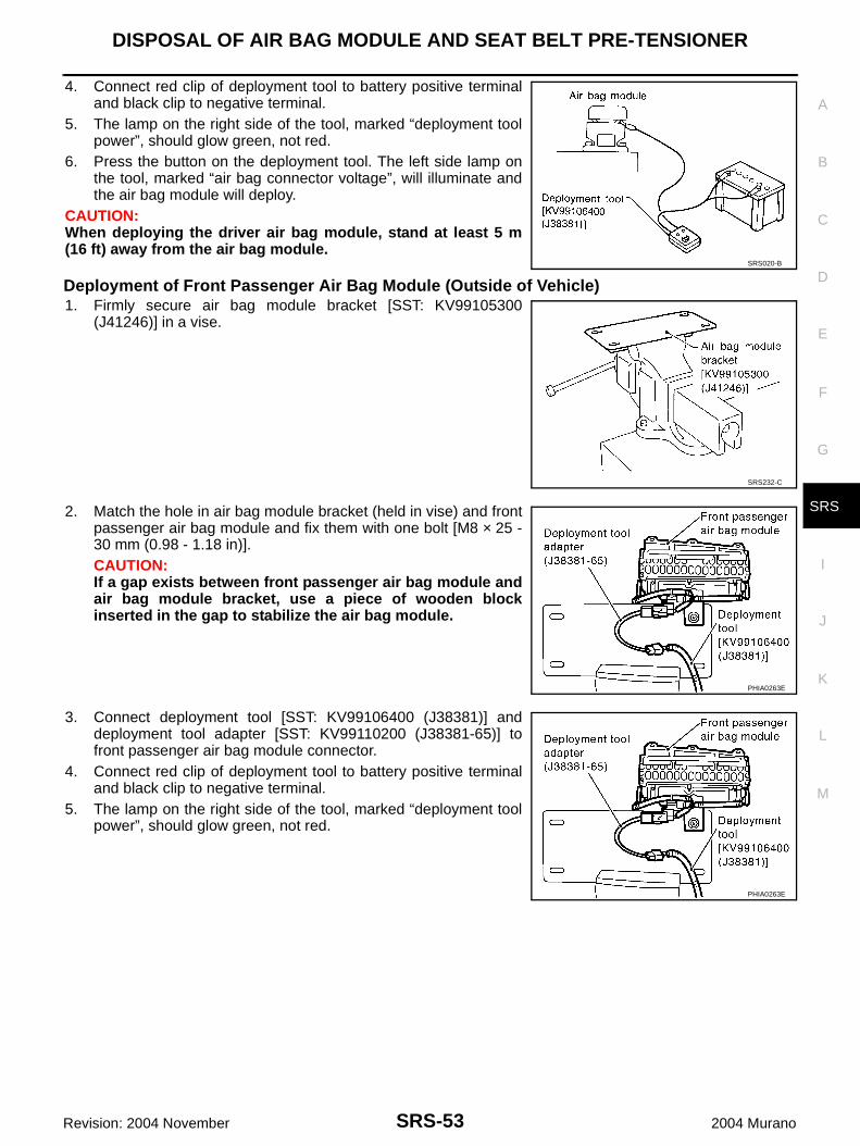
4. Connect red clip of deployment tool to battery positive terminaland black clip to negative terminal.
5. The lamp on the right side of the tool, marked “deployment toolpower”, should glow green, not red.
6. Press the button on the deployment tool. The left side lamp onthe tool, marked “air bag connector voltage”, will illuminate andthe air bag module will deploy.
CAUTION:When deploying the driver air bag module, stand at least 5 m(16 ft) away from the air bag module.
Deployment of Front Passenger Air Bag Module (Outside of Vehicle)1. Firmly secure air bag module bracket [SST: KV99105300
(J41246)] in a vise.
2. Match the hole in air bag module bracket (held in vise) and frontpassenger air bag module and fix them with one bolt [M8 × 25 -30 mm (0.98 - 1.18 in)].CAUTION:If a gap exists between front passenger air bag module andair bag module bracket, use a piece of wooden blockinserted in the gap to stabilize the air bag module.
3. Connect deployment tool [SST: KV99106400 (J38381)] anddeployment tool adapter [SST: KV99110200 (J38381-65)] tofront passenger air bag module connector.
4. Connect red clip of deployment tool to battery positive terminaland black clip to negative terminal.
5. The lamp on the right side of the tool, marked “deployment toolpower”, should glow green, not red.
SRS020-B
SRS232-C
PHIA0263E
PHIA0263E
SRS-54
DISPOSAL OF AIR BAG MODULE AND SEAT BELT PRE-TENSIONER
Revision: 2004 November 2004 Murano
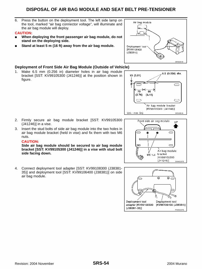
6. Press the button on the deployment tool. The left side lamp onthe tool, marked “air bag connector voltage”, will illuminate andthe air bag module will deploy.
CAUTION:● When deploying the front passenger air bag module, do not
stand on the deploying side.● Stand at least 5 m (16 ft) away from the air bag module.
Deployment of Front Side Air Bag Module (Outside of Vehicle)1. Make 6.5 mm (0.256 in) diameter holes in air bag module
bracket [SST: KV99105300 (J41246)] at the position shown infigure.
2. Firmly secure air bag module bracket [SST: KV99105300(J41246)] in a vise.
3. Insert the stud bolts of side air bag module into the two holes inair bag module bracket (held in vise) and fix them with two M6nuts.CAUTION:Side air bag module should be secured to air bag modulebracket [SST: KV99105300 (J41246)] in a vise with stud boltside facing down.
4. Connect deployment tool adapter [SST: KV99108300 (J38381-35)] and deployment tool [SST: KV99106400 (J38381)] on sideair bag module.
SRS020-B
SRS490-B
SHIA0197E
PHIA0107E
DISPOSAL OF AIR BAG MODULE AND SEAT BELT PRE-TENSIONER
SRS-55
C
D
E
F
G
I
J
K
L
M
A
B
SRS
Revision: 2004 November 2004 Murano
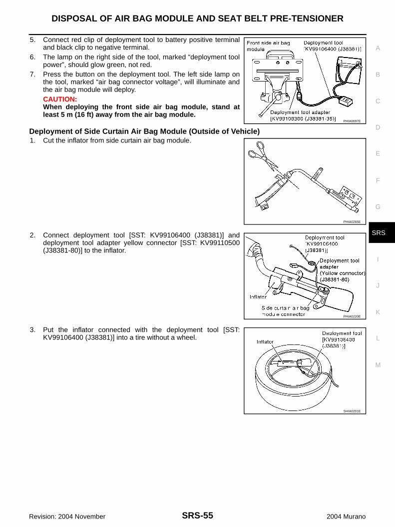
5. Connect red clip of deployment tool to battery positive terminaland black clip to negative terminal.
6. The lamp on the right side of the tool, marked “deployment toolpower”, should glow green, not red.
7. Press the button on the deployment tool. The left side lamp onthe tool, marked “air bag connector voltage”, will illuminate andthe air bag module will deploy.CAUTION:When deploying the front side air bag module, stand atleast 5 m (16 ft) away from the air bag module.
Deployment of Side Curtain Air Bag Module (Outside of Vehicle)1. Cut the inflator from side curtain air bag module.
2. Connect deployment tool [SST: KV99106400 (J38381)] anddeployment tool adapter yellow connector [SST: KV99110500(J38381-80)] to the inflator.
3. Put the inflator connected with the deployment tool [SST:KV99106400 (J38381)] into a tire without a wheel.
PHIA0697E
PHIA0265E
PHIA0220E
SHIA0201E
SRS-56
DISPOSAL OF AIR BAG MODULE AND SEAT BELT PRE-TENSIONER
Revision: 2004 November 2004 Murano
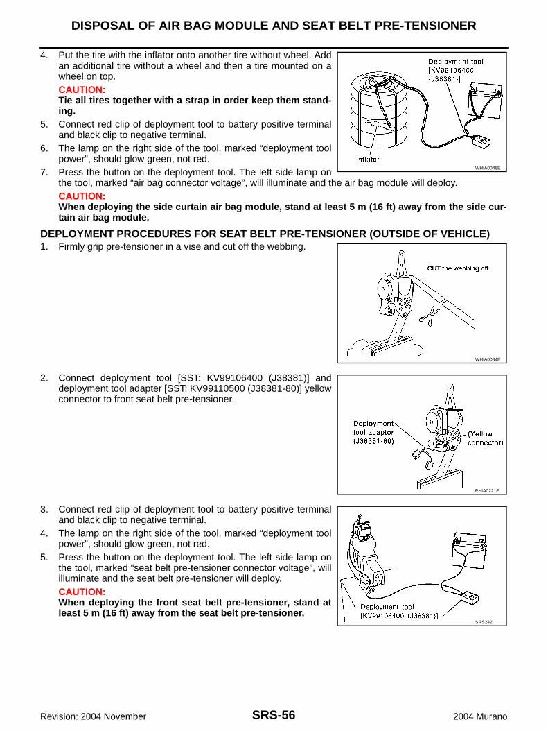
4. Put the tire with the inflator onto another tire without wheel. Addan additional tire without a wheel and then a tire mounted on awheel on top.CAUTION:Tie all tires together with a strap in order keep them stand-ing.
5. Connect red clip of deployment tool to battery positive terminaland black clip to negative terminal.
6. The lamp on the right side of the tool, marked “deployment toolpower”, should glow green, not red.
7. Press the button on the deployment tool. The left side lamp onthe tool, marked “air bag connector voltage”, will illuminate and the air bag module will deploy.CAUTION:When deploying the side curtain air bag module, stand at least 5 m (16 ft) away from the side cur-tain air bag module.
DEPLOYMENT PROCEDURES FOR SEAT BELT PRE-TENSIONER (OUTSIDE OF VEHICLE)1. Firmly grip pre-tensioner in a vise and cut off the webbing.
2. Connect deployment tool [SST: KV99106400 (J38381)] anddeployment tool adapter [SST: KV99110500 (J38381-80)] yellowconnector to front seat belt pre-tensioner.
3. Connect red clip of deployment tool to battery positive terminaland black clip to negative terminal.
4. The lamp on the right side of the tool, marked “deployment toolpower”, should glow green, not red.
5. Press the button on the deployment tool. The left side lamp onthe tool, marked “seat belt pre-tensioner connector voltage”, willilluminate and the seat belt pre-tensioner will deploy.CAUTION:When deploying the front seat belt pre-tensioner, stand atleast 5 m (16 ft) away from the seat belt pre-tensioner.
WHIA0048E
WHIA0034E
PHIA0221E
SRS242
DISPOSAL OF AIR BAG MODULE AND SEAT BELT PRE-TENSIONER
SRS-57
C
D
E
F
G
I
J
K
L
M
A
B
SRS
Revision: 2004 November 2004 Murano
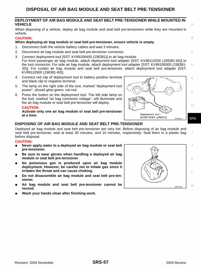
DEPLOYMENT OF AIR BAG MODULE AND SEAT BELT PRE-TENSIONER WHILE MOUNTED IN VEHICLEWhen disposing of a vehicle, deploy air bag module and seat belt pre-tensioners while they are mounted invehicle.CAUTION:When deploying air bag module or seat belt pre-tensioner, ensure vehicle is empty.1. Disconnect both the vehicle battery cables and wait 3 minutes.2. Disconnect air bag module and seat belt pre-tensioner connector.3. Connect deployment tool [SST: KV99106400 (J38381)] to air bag module.
For front passenger air bag module, attach deployment tool adapter [SST: KV99110200 (J38381-65)] tothe tool connector. For side air bag module, attach deployment tool adapter [SST: KV99108300 (J38381-35)]. For curtain air bag module and seat belt pre-tensioner, attach deployment tool adapter [SST:KV99110500 (J38381-80)].
4. Connect red clip of deployment tool to battery positive terminaland black clip to negative terminal.
5. The lamp on the right side of the tool, marked “deployment toolpower”, should glow green, not red.
6. Press the button on the deployment tool. The left side lamp onthe tool, marked “air bag connector voltage”, will illuminate andthe air bag module or seat belt pre-tensioner will deploy.CAUTION:Activate only one air bag module or seat belt pre-tensionerat a time.
DISPOSING OF AIR BAG MODULE AND SEAT BELT PRE-TENSIONERDeployed air bag module and seat belt pre-tensioner are very hot. Before disposing of air bag module andseat belt pre-tensioner, wait at least 30 minutes, and 10 minutes, respectively. Seal them in a plastic bagbefore disposal.CAUTION:● Never apply water to a deployed air bag module or seat belt
pre-tensioner.● Be sure to wear gloves when handling a deployed air bag
module or seat belt pre-tensioner.● No poisonous gas is produced upon air bag module
deployment. However, be careful not to inhale gas since itirritates the throat and can cause choking.
● Do not disassemble air bag module and seat belt pre-ten-sioner.
● Air bag module and seat belt pre-tensioner cannot bereused.
● Wash your hands clean after finishing work.
SRS006-C
SBF276H
SRS-58
COLLISION DIAGNOSIS
Revision: 2004 November 2004 Murano
COLLISION DIAGNOSIS PFP:00015
For Frontal Collision AHS000EG
To repair the SRS, perform the following steps.When SRS (except the front side air bag and side curtain air bag modules) is activated in a collision:1. Replace the diagnosis sensor unit.2. Remove the air bag modules (except the front side air bag modules and side curtain air bag modules),
crash zone sensor assembly, bracket and seat belt pre-tensioner assemblies.3. Check the SRS components using the table below:– Replace any SRS components showing visible signs of damage (dents, cracks and deformation).4. Install new air bag modules (except the front side air bag modules and side curtain air bag modules) crash
zone sensor assembly, bracket and seat belt pre-tensioner assemblies.5. Conduct self-diagnosis using CONSULT-II or “AIR BAG” warning lamp. Refer to SRS-17, "SRS Operation
Check" for details. Ensure entire SRS operates properly.When SRS is not activated in a collision:1. Check the SRS components using the table below:– Replace any SRS components showing visible signs of damage (dents, cracks and deformation).2. Conduct self-diagnosis using CONSULT-II or “AIR BAG” warning lamp. Refer to SRS-17, "SRS Operation
Check" for details. Ensure entire SRS operates properly.When only one front air bag module is activated in a collision:1. Replace the following components:– Diagnosis sensor unit– Crash zone sensor– Activated front air bag and seat belt pre-tensioner.2. Check the other SRS components using the table below. (Refer to “SRS is NOT activated”.)– Replace any SRS components showing visible signs of damage (dents, cracks and deformation).3. Conduct self-diagnosis using CONSULT-II or “AIR BAG” warning lamp. Refer to SRS-17, "SRS Operation
Check" for details. Ensure entire SRS operates properly.Only one front air bag may inflate a crash, depending on the crash severity and whether the front occupantsare belted or unbelted. This does not indicate improper performance of the system. Perform self-diagnosis tomake sure the entire SRS operates properly.
SRS INSPECTION (FOR FRONTAL COLLISION)Part SRS is activated SRS is NOT activated
Air bag module (driver and front pas-senger air bag mod-ule)
REPLACEInstall with new bolts.
1. Remove air bag module. Check harness cover and connectors for damage, termi-nals for deformities, and harness for binding.
2.
– Install driver air bag module into the steering wheel to check fit and alignment with the wheel.
– Install passenger air bag module into the instrument panel to check fit with the instrument panel.
3. No damage found, reinstall with new bolts.
4. If damaged—REPLACE air bag modules with new special bolts.Air bag must be deployed before disposal.
Crash zone sensor REPLACE the crash zone sensor and bracket with new nuts.
1. Remove the crash zone sensor. Check harness connectors for damage, terminals for deformities, and harness for binding.
2. Check for visible signs of damage (dents, cracks, deformation) of the crash zone sensor and bracket.
3. Install the crash zone sensor to check fit.
4. No damage found, reinstall with new bolts.
5. If damaged—REPLACE the crash zone sensor and bracket with new nuts.
COLLISION DIAGNOSIS
SRS-59
C
D
E
F
G
I
J
K
L
M
A
B
SRS
Revision: 2004 November 2004 Murano
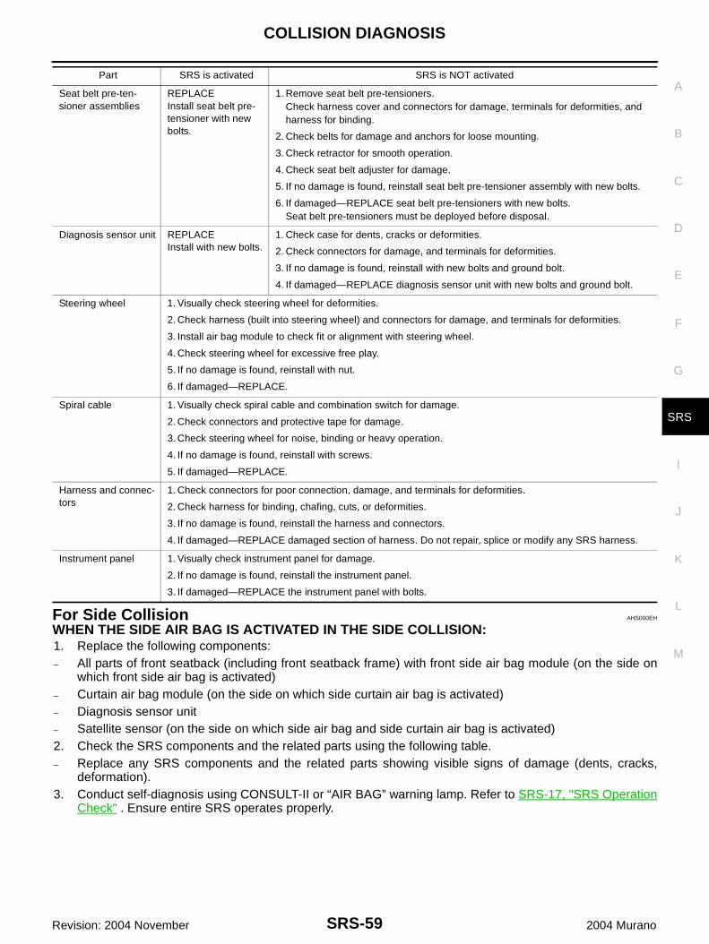
For Side Collision AHS000EH
WHEN THE SIDE AIR BAG IS ACTIVATED IN THE SIDE COLLISION:1. Replace the following components:– All parts of front seatback (including front seatback frame) with front side air bag module (on the side on
which front side air bag is activated)– Curtain air bag module (on the side on which side curtain air bag is activated)– Diagnosis sensor unit– Satellite sensor (on the side on which side air bag and side curtain air bag is activated)2. Check the SRS components and the related parts using the following table.– Replace any SRS components and the related parts showing visible signs of damage (dents, cracks,
deformation).3. Conduct self-diagnosis using CONSULT-II or “AIR BAG” warning lamp. Refer to SRS-17, "SRS Operation
Check" . Ensure entire SRS operates properly.
Seat belt pre-ten-sioner assemblies
REPLACEInstall seat belt pre-tensioner with new bolts.
1. Remove seat belt pre-tensioners.Check harness cover and connectors for damage, terminals for deformities, and harness for binding.
2. Check belts for damage and anchors for loose mounting.
3. Check retractor for smooth operation.
4. Check seat belt adjuster for damage.
5. If no damage is found, reinstall seat belt pre-tensioner assembly with new bolts.
6. If damaged—REPLACE seat belt pre-tensioners with new bolts.Seat belt pre-tensioners must be deployed before disposal.
Diagnosis sensor unit REPLACEInstall with new bolts.
1. Check case for dents, cracks or deformities.
2. Check connectors for damage, and terminals for deformities.
3. If no damage is found, reinstall with new bolts and ground bolt.
4. If damaged—REPLACE diagnosis sensor unit with new bolts and ground bolt.
Steering wheel 1. Visually check steering wheel for deformities.
2. Check harness (built into steering wheel) and connectors for damage, and terminals for deformities.
3. Install air bag module to check fit or alignment with steering wheel.
4. Check steering wheel for excessive free play.
5. If no damage is found, reinstall with nut.
6. If damaged—REPLACE.
Spiral cable 1. Visually check spiral cable and combination switch for damage.
2. Check connectors and protective tape for damage.
3. Check steering wheel for noise, binding or heavy operation.
4. If no damage is found, reinstall with screws.
5. If damaged—REPLACE.
Harness and connec-tors
1. Check connectors for poor connection, damage, and terminals for deformities.
2. Check harness for binding, chafing, cuts, or deformities.
3. If no damage is found, reinstall the harness and connectors.
4. If damaged—REPLACE damaged section of harness. Do not repair, splice or modify any SRS harness.
Instrument panel 1. Visually check instrument panel for damage.
2. If no damage is found, reinstall the instrument panel.
3. If damaged—REPLACE the instrument panel with bolts.
Part SRS is activated SRS is NOT activated
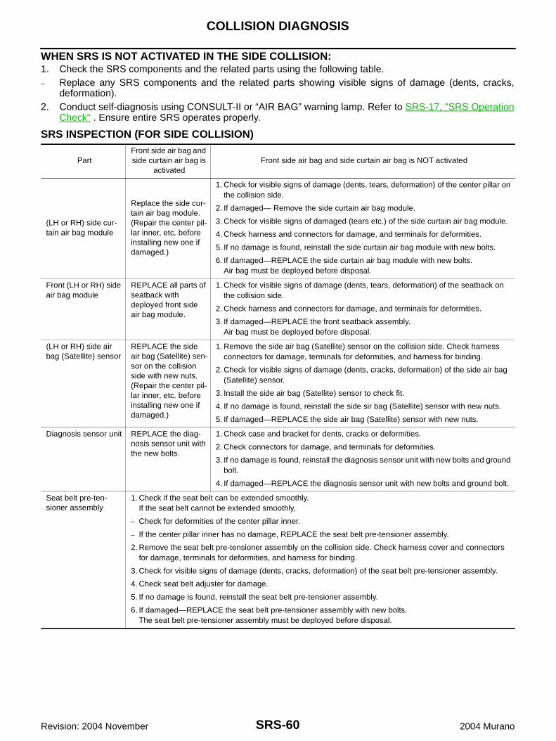
SRS-60
COLLISION DIAGNOSIS
Revision: 2004 November 2004 Murano
WHEN SRS IS NOT ACTIVATED IN THE SIDE COLLISION:1. Check the SRS components and the related parts using the following table.– Replace any SRS components and the related parts showing visible signs of damage (dents, cracks,
deformation).2. Conduct self-diagnosis using CONSULT-II or “AIR BAG” warning lamp. Refer to SRS-17, "SRS Operation
Check" . Ensure entire SRS operates properly.
SRS INSPECTION (FOR SIDE COLLISION)
PartFront side air bag and side curtain air bag is
activatedFront side air bag and side curtain air bag is NOT activated
(LH or RH) side cur-tain air bag module
Replace the side cur-tain air bag module.(Repair the center pil-lar inner, etc. before installing new one if damaged.)
1. Check for visible signs of damage (dents, tears, deformation) of the center pillar on the collision side.
2. If damaged— Remove the side curtain air bag module.
3. Check for visible signs of damaged (tears etc.) of the side curtain air bag module.
4. Check harness and connectors for damage, and terminals for deformities.
5. If no damage is found, reinstall the side curtain air bag module with new bolts.
6. If damaged—REPLACE the side curtain air bag module with new bolts.Air bag must be deployed before disposal.
Front (LH or RH) side air bag module
REPLACE all parts of seatback with deployed front side air bag module.
1. Check for visible signs of damage (dents, tears, deformation) of the seatback on the collision side.
2. Check harness and connectors for damage, and terminals for deformities.
3. If damaged—REPLACE the front seatback assembly.Air bag must be deployed before disposal.
(LH or RH) side air bag (Satellite) sensor
REPLACE the side air bag (Satellite) sen-sor on the collision side with new nuts.(Repair the center pil-lar inner, etc. before installing new one if damaged.)
1. Remove the side air bag (Satellite) sensor on the collision side. Check harness connectors for damage, terminals for deformities, and harness for binding.
2. Check for visible signs of damage (dents, cracks, deformation) of the side air bag (Satellite) sensor.
3. Install the side air bag (Satellite) sensor to check fit.
4. If no damage is found, reinstall the side sir bag (Satellite) sensor with new nuts.
5. If damaged—REPLACE the side air bag (Satellite) sensor with new nuts.
Diagnosis sensor unit REPLACE the diag-nosis sensor unit with the new bolts.
1. Check case and bracket for dents, cracks or deformities.
2. Check connectors for damage, and terminals for deformities.
3. If no damage is found, reinstall the diagnosis sensor unit with new bolts and ground bolt.
4. If damaged—REPLACE the diagnosis sensor unit with new bolts and ground bolt.
Seat belt pre-ten-sioner assembly
1. Check if the seat belt can be extended smoothly.If the seat belt cannot be extended smoothly,
– Check for deformities of the center pillar inner.
– If the center pillar inner has no damage, REPLACE the seat belt pre-tensioner assembly.
2. Remove the seat belt pre-tensioner assembly on the collision side. Check harness cover and connectors for damage, terminals for deformities, and harness for binding.
3. Check for visible signs of damage (dents, cracks, deformation) of the seat belt pre-tensioner assembly.
4. Check seat belt adjuster for damage.
5. If no damage is found, reinstall the seat belt pre-tensioner assembly.
6. If damaged—REPLACE the seat belt pre-tensioner assembly with new bolts.The seat belt pre-tensioner assembly must be deployed before disposal.
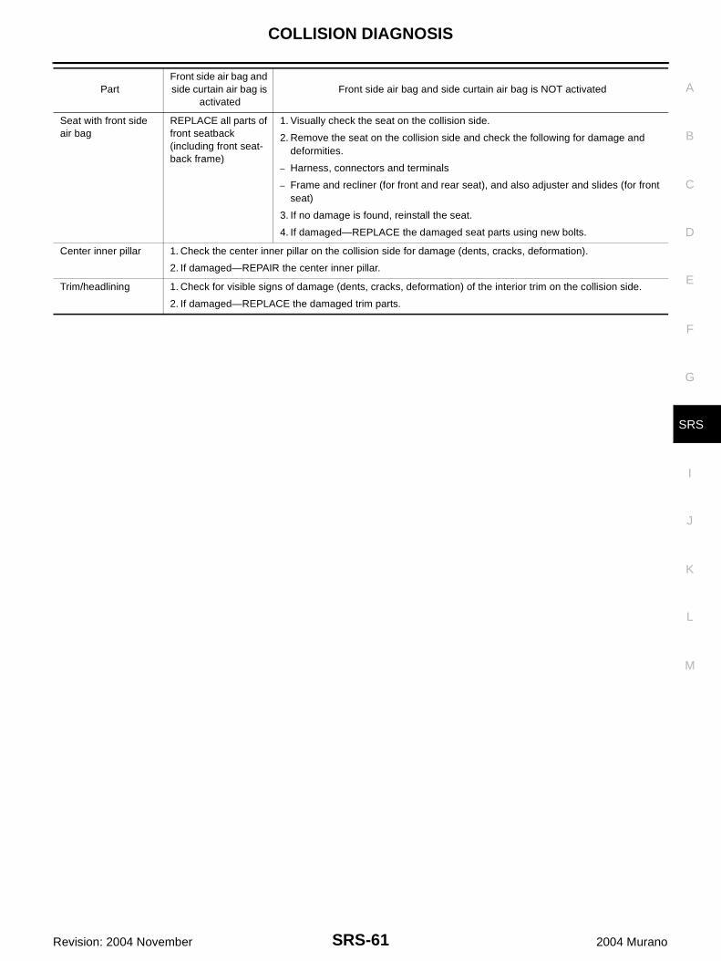
COLLISION DIAGNOSIS
SRS-61
C
D
E
F
G
I
J
K
L
M
A
B
SRS
Revision: 2004 November 2004 Murano
Seat with front side air bag
REPLACE all parts of front seatback (including front seat-back frame)
1. Visually check the seat on the collision side.
2. Remove the seat on the collision side and check the following for damage and deformities.
– Harness, connectors and terminals
– Frame and recliner (for front and rear seat), and also adjuster and slides (for front seat)
3. If no damage is found, reinstall the seat.
4. If damaged—REPLACE the damaged seat parts using new bolts.
Center inner pillar 1. Check the center inner pillar on the collision side for damage (dents, cracks, deformation).
2. If damaged—REPAIR the center inner pillar.
Trim/headlining 1. Check for visible signs of damage (dents, cracks, deformation) of the interior trim on the collision side.
2. If damaged—REPLACE the damaged trim parts.
PartFront side air bag and side curtain air bag is
activatedFront side air bag and side curtain air bag is NOT activated
SRS-62
COLLISION DIAGNOSIS
Revision: 2004 November 2004 Murano