Embed Size (px)
Citation preview
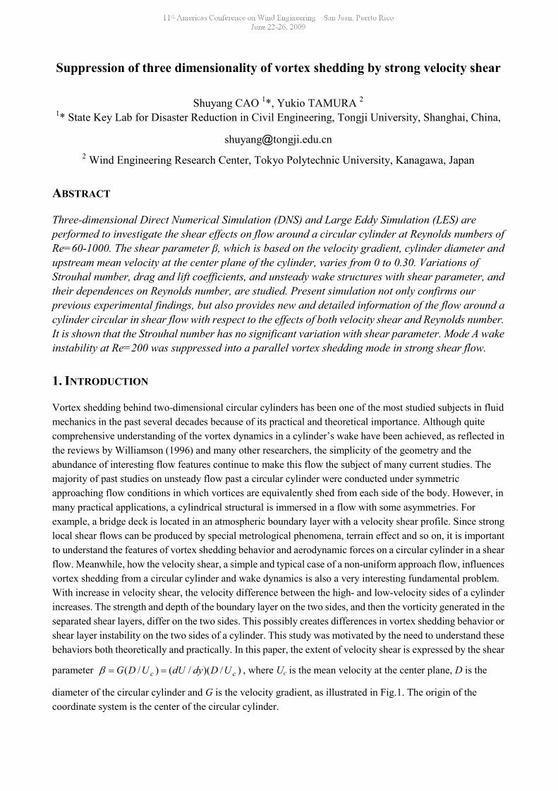
Suppression of three dimensionality of vortex shedding by strong velocity shear
Shuyang CAO 1*, Yukio TAMURA 2
1* State Key Lab for Disaster Reduction in Civil Engineering, Tongji University, Shanghai, China,
shuyang@tongji.edu.cn2 Wind Engineering Research Center, Tokyo Polytechnic University, Kanagawa, Japan
ABSTRACT
Three-dimensional Direct Numerical Simulation (DNS) and Large Eddy Simulation (LES) areperformed to investigate the shear effects on flow around a circular cylinder at Reynolds numbers ofRe=60-1000. The shear parameter β, which is based on the velocity gradient, cylinder diameter andupstream mean velocity at the center plane of the cylinder, varies from 0 to 0.30. Variations ofStrouhal number, drag and lift coefficients, and unsteady wake structures with shear parameter, andtheir dependences on Reynolds number, are studied. Present simulation not only confirms ourprevious experimental findings, but also provides new and detailed information of the flow around acylinder circular in shear flow with respect to the effects of both velocity shear and Reynolds number.It is shown that the Strouhal number has no significant variation with shear parameter. Mode A wakeinstability at Re=200 was suppressed into a parallel vortex shedding mode in strong shear flow.
1. INTRODUCTION
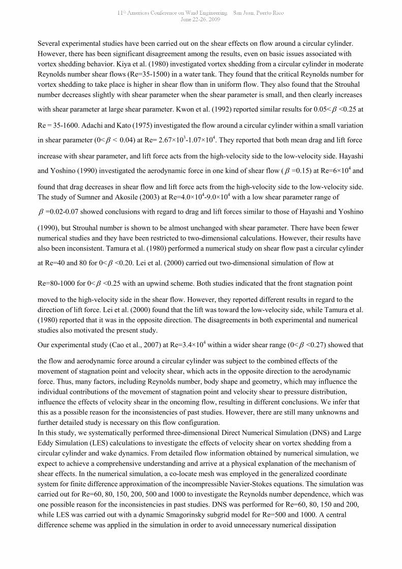
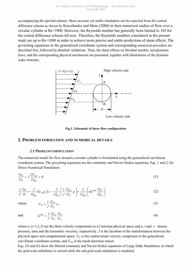
Vortex shedding behind two-dimensional circular cylinders has been one of the most studied subjects in fluidmechanics in the past several decades because of its practical and theoretical importance. Although quitecomprehensive understanding of the vortex dynamics in a cylinder’s wake have been achieved, as reflected inthe reviews by Williamson (1996) and many other researchers, the simplicity of the geometry and theabundance of interesting flow features continue to make this flow the subject of many current studies. Themajority of past studies on unsteady flow past a circular cylinder were conducted under symmetricapproaching flow conditions in which vortices are equivalently shed from each side of the body. However, inmany practical applications, a cylindrical structural is immersed in a flow with some asymmetries. Forexample, a bridge deck is located in an atmospheric boundary layer with a velocity shear profile. Since stronglocal shear flows can be produced by special metrological phenomena, terrain effect and so on, it is importantto understand the features of vortex shedding behavior and aerodynamic forces on a circular cylinder in a shearflow. Meanwhile, how the velocity shear, a simple and typical case of a non-uniform approach flow, influencesvortex shedding from a circular cylinder and wake dynamics is also a very interesting fundamental problem.With increase in velocity shear, the velocity difference between the high- and low-velocity sides of a cylinderincreases. The strength and depth of the boundary layer on the two sides, and then the vorticity generated in theseparated shear layers, differ on the two sides. This possibly creates differences in vortex shedding behavior orshear layer instability on the two sides of a cylinder. This study was motivated by the need to understand thesebehaviors both theoretically and practically. In this paper, the extent of velocity shear is expressed by the shear
parameter )/)(/()/( cc UDdydUUDG , where Uc is the mean velocity at the center plane, D is the
diameter of the circular cylinder and G is the velocity gradient, as illustrated in Fig.1. The origin of thecoordinate system is the center of the circular cylinder.
Several experimental studies have been carried out on the shear effects on flow around a circular cylinder.However, there has been significant disagreement among the results, even on basic issues associated withvortex shedding behavior. Kiya et al. (1980) investigated vortex shedding from a circular cylinder in moderateReynolds number shear flows (Re=35-1500) in a water tank. They found that the critical Reynolds number forvortex shedding to take place is higher in shear flow than in uniform flow. They also found that the Strouhalnumber decreases slightly with shear parameter when the shear parameter is small, and then clearly increases
with shear parameter at large shear parameter. Kwon et al. (1992) reported similar results for 0.05< <0.25 at
Re = 35-1600. Adachi and Kato (1975) investigated the flow around a circular cylinder within a small variation
in shear parameter (0< < 0.04) at Re= 2.67×10³-1.07×10⁴. They reported that both mean drag and lift force
increase with shear parameter, and lift force acts from the high-velocity side to the low-velocity side. Hayashi
and Yoshino (1990) investigated the aerodynamic force in one kind of shear flow ( =0.15) at Re=6×10⁴ and
found that drag decreases in shear flow and lift force acts from the high-velocity side to the low-velocity side.The study of Sumner and Akosile (2003) at Re=4.0×10⁴-9.0×10⁴ with a low shear parameter range of
=0.02-0.07 showed conclusions with regard to drag and lift forces similar to those of Hayashi and Yoshino
(1990), but Strouhal number is shown to be almost unchanged with shear parameter. There have been fewernumerical studies and they have been restricted to two-dimensional calculations. However, their results havealso been inconsistent. Tamura et al. (1980) performed a numerical study on shear flow past a circular cylinder
at Re=40 and 80 for 0< <0.20. Lei et al. (2000) carried out two-dimensional simulation of flow at
Re=80-1000 for 0< <0.25 with an upwind scheme. Both studies indicated that the front stagnation point
moved to the high-velocity side in the shear flow. However, they reported different results in regard to thedirection of lift force. Lei et al. (2000) found that the lift was toward the low-velocity side, while Tamura et al.(1980) reported that it was in the opposite direction. The disagreements in both experimental and numericalstudies also motivated the present study.
Our experimental study (Cao et al., 2007) at Re=3.4×10⁴ within a wider shear range (0< <0.27) showed that
the flow and aerodynamic force around a circular cylinder was subject to the combined effects of themovement of stagnation point and velocity shear, which acts in the opposite direction to the aerodynamicforce. Thus, many factors, including Reynolds number, body shape and geometry, which may influence theindividual contributions of the movement of stagnation point and velocity shear to pressure distribution,influence the effects of velocity shear in the oncoming flow, resulting in different conclusions. We infer thatthis as a possible reason for the inconsistencies of past studies. However, there are still many unknowns andfurther detailed study is necessary on this flow configuration.In this study, we systematically performed three-dimensional Direct Numerical Simulation (DNS) and LargeEddy Simulation (LES) calculations to investigate the effects of velocity shear on vortex shedding from acircular cylinder and wake dynamics. From detailed flow information obtained by numerical simulation, weexpect to achieve a comprehensive understanding and arrive at a physical explanation of the mechanism ofshear effects. In the numerical simulation, a co-locate mesh was employed in the generalized coordinatesystem for finite difference approximation of the incompressible Navier-Stokes equations. The simulation wascarried out for Re=60, 80, 150, 200, 500 and 1000 to investigate the Reynolds number dependence, which wasone possible reason for the inconsistencies in past studies. DNS was performed for Re=60, 80, 150 and 200,while LES was carried out with a dynamic Smagorinsky subgrid model for Re=500 and 1000. A centraldifference scheme was applied in the simulation in order to avoid unnecessary numerical dissipation
accompanying the upwind scheme. More accurate yet stable simulation can be expected from the centraldifference scheme as shown by Kravchenko and Moin (2000) in their numerical studies of flow over acircular cylinder at Re=3900. However, the Reynolds number has generally been limited to 103 forthe central difference scheme till now. Therefore, the Reynolds numbers considered in the presentstudy are up to Re=1000 in order to achieve more precise and stable predictions of shear effects. Thegoverning equations in the generalized coordinate system and corresponding numerical procedure aredescribed first, followed by detailed validations. Then, the shear effects on Strouhal number, aerodynamicforce, and the corresponding physical mechanism are presented, together with illustrations of the dynamicwake structure.
Fig.1. Schematic of shear flow configuration
2. PROBLEM FORMATION AND NUMERICAL DETAILS
2.1 PROBLEM FORMULATION
The numerical model for flow around a circular cylinder is formulated using the generalized curvilinearcoordinate system. The governing equations are the continuity and Navier-Stokes equations, Eqs. 1 and 2, forDirect Numerical Simulation:
0
m
m
i
i UJxu
(1)
n
imn
mi
m
mim
m
i uGp
xJuU
tu
J
11 (2)
where ii
mm u
xJU
1 (3)
andj
n
i
mmn
xxJG
1 (4)
where ui (i=1,2,3) are the three velocity components in a Cartesian physical space and p, t and denotepressure, time and the kinematic viscosity, respectively. J is the Jacobian of the transformation between thephysical space and computational space. Um is the contravariant velocity component in the generalizedcurvilinear coordinate system, and Gmn is the mesh skewness tensor.Eqs. (5) and (6) show the filtered continuity and Navier-Stokes equations of Large Eddy Simulation, in whichthe grid-scale turbulence is solved while the sub-grid-scale turbulence is modeled.
U=Gy+Uc
Uc
D
x
yHigh velocity side
Low velocity side
A
B
UA
UB
0
m
m
i
i UJxu
(5)
ijj
m
mn
imn
mi
m
mim
m
i
xJu
GpxJ
uUt
uJ
11)(1 (6)
where jijiij uuuu , and all the variables are given as filtered components. The anisotropic part of the SGS
stress can be expressed by Eq.(7),
ijkkij
ij S
23
(7)
where SCJSC 3/22 and
n
j
i
n
m
i
j
mij
xu
xu
xS
21 .
The dynamic procedure based on the Smagorinsky model proposed by Germano et al. (1991) is used todetermine the unknown model coefficient C in the following procedure.
The ratio of test filter scale to grid filter scale is the only parameter in the procedure and is chosen to be 2.0, assuggested by Germano et al. (1991). Averaging and test filter operation are performed only in thehomogeneous spanwise direction, in conjunction with Lilly’s least-squares technique (1992). In order to avoidnumerical instability, the negative value of SGS eddy viscosity is truncated to zero. Large Eddy Simulationusing the dynamic Smagorinsky model has been widely utilized as a relatively affordable and easy-to-useapproach to simulate separated flow and other complicated flow (Kravchenko and Moin 2000).
2.2 NUMERICAL DISCRETIZATION AND ALGORITHM
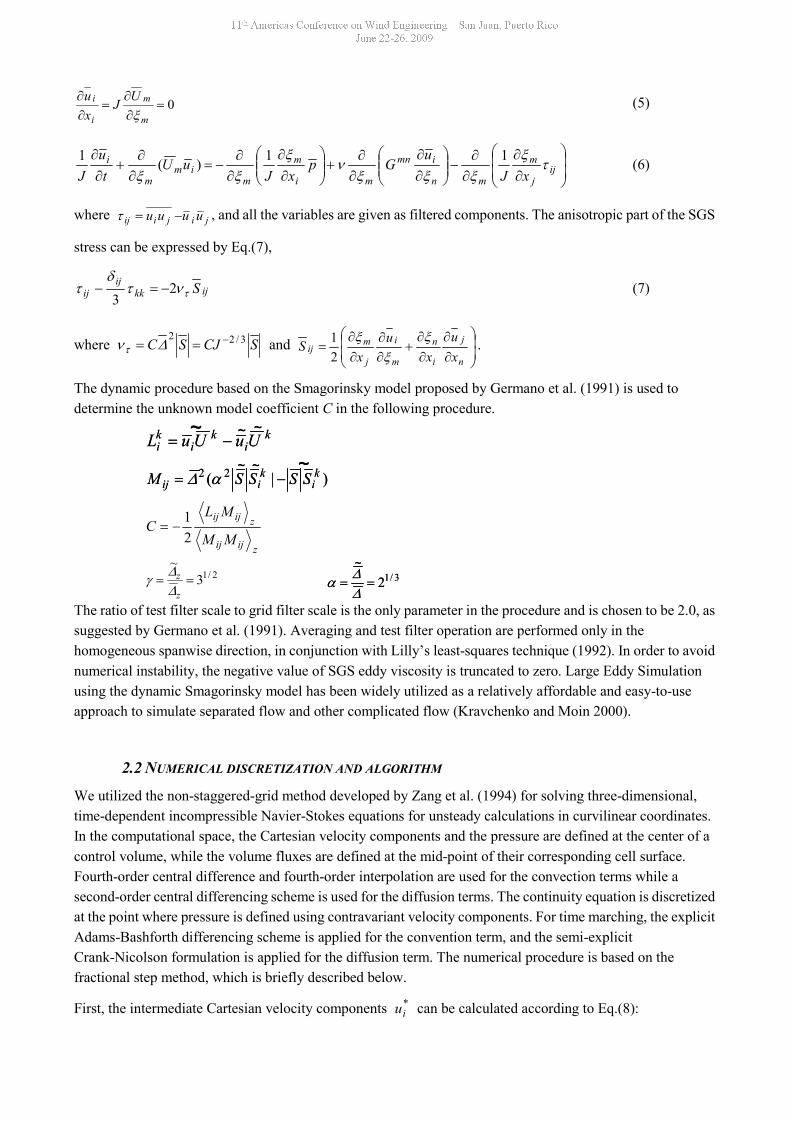
We utilized the non-staggered-grid method developed by Zang et al. (1994) for solving three-dimensional,time-dependent incompressible Navier-Stokes equations for unsteady calculations in curvilinear coordinates.In the computational space, the Cartesian velocity components and the pressure are defined at the center of acontrol volume, while the volume fluxes are defined at the mid-point of their corresponding cell surface.Fourth-order central difference and fourth-order interpolation are used for the convection terms while asecond-order central differencing scheme is used for the diffusion terms. The continuity equation is discretizedat the point where pressure is defined using contravariant velocity components. For time marching, the explicitAdams-Bashforth differencing scheme is applied for the convention term, and the semi-explicitCrank-Nicolson formulation is applied for the diffusion term. The numerical procedure is based on thefractional step method, which is briefly described below.
First, the intermediate Cartesian velocity components *iu can be calculated according to Eq.(8):
zijij
zijij
MM
MLC
21
2/13~
z
z 3/12
~
3/12~
ki
ki
ki UuUuL
~~ ~ki
ki
ki UuUuL
~~ ~
)|( 22 ki
kiij SSSSM
~~ ~)|( 22 k
ikiij SSSSM
~~ ~
))(
(21
21
23 *
1*
n
niimn
m
ni
ni
nii
uuGCCJtuu
(8)
where nim
m
ni uUC )(
for DNS, orn
ijj
m
m
nim
m
ni xJ
uUC
1)( for LES. By
conducting coordinate transform on *iu , the contravariant velocity components at the cell center can be
obtained and they can be interpolated to contravariant velocity components *mU defined at the cell surface.
Then, the potential field of the next step can be computed iteratively by solving the Poisson equation, Eq.(9),using the successive over-relaxation (SOR) method.
)1)(*1
m
m
n
nmn
m
Ut
G
(9)
m
n
i
mi
ni x
tuu
1
*1 (10)
n
nmn
mnm GtUU
1*1 (11)
Finally, the contravariant and cartesian velocity components of the next step can be calculated from Eqs(10)and (11), respectively. This algorithm has been widely utilized in numerical simulations (Tamura 2008).
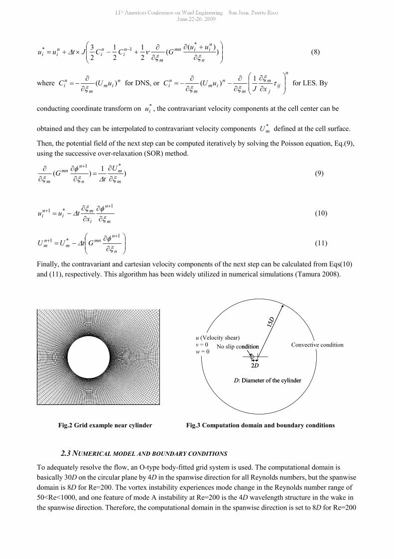
Fig.2 Grid example near cylinder Fig.3 Computation domain and boundary conditions
2.3 NUMERICAL MODEL AND BOUNDARY CONDITIONS
To adequately resolve the flow, an O-type body-fitted grid system is used. The computational domain isbasically 30D on the circular plane by 4D in the spanwise direction for all Reynolds numbers, but the spanwisedomain is 8D for Re=200. The vortex instability experiences mode change in the Reynolds number range of50<Re<1000, and one feature of mode A instability at Re=200 is the 4D wavelength structure in the wake inthe spanwise direction. Therefore, the computational domain in the spanwise direction is set to 8D for Re=200
15D
2D
u (Velocity shear)v = 0w = 0
Convective condition
D: Diameter of the cylinder
No slip condition
15D
2D
u (Velocity shear)v = 0w = 0
Convective condition
D: Diameter of the cylinder
No slip condition
in order to illustrate mode A wake dynamics more directly. Grid number on the circular plane is 160×140 forall Reynolds numbers, while it is 40 or 80 in the spanwise direction, depending on whether the computational
domain is 4D or 8D. The size of the first grid near the body surface is Re/1.0 , and it stretches outwards to
the boundary. Fig.2 illustrates a grid example near the cylinder.The boundary conditions for simulation shown in Fig.3 are as follows:Cylinder body surface: No slip condition for velocity; Neumann condition for pressure;Inlet: Specified mean velocity profile; Neumann condition for pressure;
Outflow boundary: Convective boundary condition of the form 0
xc
t is applied for velocity and
pressure. In order to ensure global mass conservation, c is taken to be the bulk velocity.Spanwise: Periodic condition for velocity and pressure;
In addition, proper boundary conditions for the intermediate (split) velocity field, inn
ii xtuu 1* ,
proposed by Kim and Moin (1985) to guarantee the precision of discretization, are imposed.
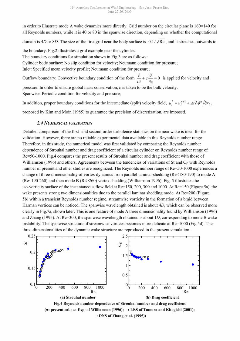
2.4 NUMERICAL VALIDATION
Detailed comparison of the first- and second-order turbulence statistics on the near wake is ideal for thevalidation. However, there are no reliable experimental data available in this Reynolds number range.Therefore, in this study, the numerical model was first validated by comparing the Reynolds numberdependence of Strouhal number and drag coefficient of a circular cylinder on Reynolds number range ofRe=50-1000. Fig.4 compares the present results of Strouhal number and drag coefficient with those ofWilliamson (1996) and others. Agreements between the tendencies of variations of St and CD with Reynoldsnumber of present and other studies are recognized. The Reynolds number range of Re=50-1000 experiences achange of three-dimensionality of vortex dynamics from parallel laminar shedding (Re<180-190) to mode A(Re~190-260) and then mode B (Re>260) vortex shedding (Williamson 1996). Fig. 5 illustrates theiso-vorticity surface of the instantaneous flow field at Re=150, 200, 300 and 1000. At Re=150 (Figure 5a), thewake presents strong two dimensionalities due to the parallel laminar shedding mode. At Re=200 (Figure5b) within a transient Reynolds number regime, streamwise vorticity in the formation of a braid betweenKarman vortices can be noticed. The spanwise wavelength obtained is about 4D, which can be observed moreclearly in Fig.7a, shown later. This is one feature of mode A three dimensionality found by Williamson (1996)and Zhang (1995). At Re=300, the spanwise wavelength obtained is about 1D, corresponding to mode B wakeinstability. The spanwise structure of streamwise vortices becomes more delicate at Re=1000 (Fig.5d). Thethree-dimensionalities of the dynamic wake structure are reproduced in the present simulation.
(a) Strouhal number (b) Drag coefficientFig.4 Reynolds number dependence of Strouhal number and drag coefficient
(●: present cal.; ○: Exp. of Williamson (1996); : LES of Tamura and Kitagishi (2001);: DNS of Zhang et al. (1995))
0 200 400 600 800 10000.1
0.15
0.2
0.25
Re
St
0 200 400 600 800 10000
0.5
1
1.5
2
2.5
Re
CD
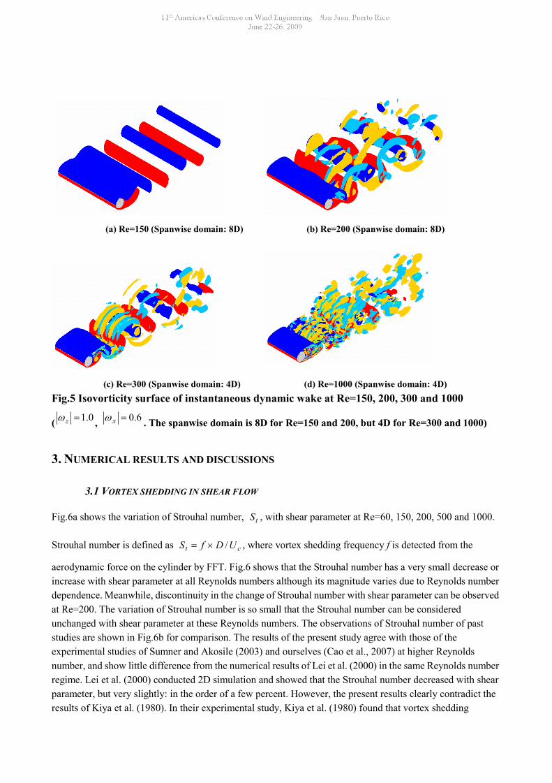
(a) Re=150 (Spanwise domain: 8D) (b) Re=200 (Spanwise domain: 8D)
(c) Re=300 (Spanwise domain: 4D) (d) Re=1000 (Spanwise domain: 4D)Fig.5 Isovorticity surface of instantaneous dynamic wake at Re=150, 200, 300 and 1000
( 0.1z , 6.0x . The spanwise domain is 8D for Re=150 and 200, but 4D for Re=300 and 1000)
3. NUMERICAL RESULTS AND DISCUSSIONS
3.1 VORTEX SHEDDING IN SHEAR FLOW
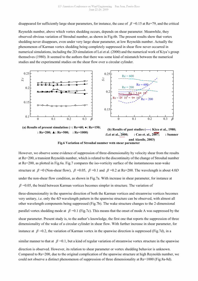
Fig.6a shows the variation of Strouhal number, tS , with shear parameter at Re=60, 150, 200, 500 and 1000.
Strouhal number is defined as ct UDfS / , where vortex shedding frequency f is detected from the
aerodynamic force on the cylinder by FFT. Fig.6 shows that the Strouhal number has a very small decrease orincrease with shear parameter at all Reynolds numbers although its magnitude varies due to Reynolds numberdependence. Meanwhile, discontinuity in the change of Strouhal number with shear parameter can be observedat Re=200. The variation of Strouhal number is so small that the Strouhal number can be consideredunchanged with shear parameter at these Reynolds numbers. The observations of Strouhal number of paststudies are shown in Fig.6b for comparison. The results of the present study agree with those of theexperimental studies of Sumner and Akosile (2003) and ourselves (Cao et al., 2007) at higher Reynoldsnumber, and show little difference from the numerical results of Lei et al. (2000) in the same Reynolds numberregime. Lei et al. (2000) conducted 2D simulation and showed that the Strouhal number decreased with shearparameter, but very slightly: in the order of a few percent. However, the present results clearly contradict theresults of Kiya et al. (1980). In their experimental study, Kiya et al. (1980) found that vortex shedding
disappeared for sufficiently large shear parameters, for instance, the case of =0.15 at Re=79, and the critical
Reynolds number, above which vortex shedding occurs, depends on shear parameter. Meanwhile, theyobserved obvious variation of Strouhal number, as shown in Fig.6b. The present results show that vortexshedding never disappears, even under very large shear parameter, at low Reynolds number. Actually thephenomenon of Karman vortex shedding being completely suppressed in shear flow never occurred innumerical simulations, including the 2D simulation of Lei et al. (2000) and the numerical work of Kiya’s groupthemselves (1980). It seemed to the authors that there was some kind of mismatch between the numericalstudies and the experimental studies on the shear flow over a circular cylinder.
Fig.6 Variation of Strouhal number with shear parameter
However, we observe some evidence of suppression of three-dimensionality by velocity shear from the resultsat Re=200, a transient Reynolds number, which is related to the discontinuity of the change of Strouhal numberat Re=200, as plotted in Fig.6a. Fig.7 compares the iso-vorticity surface of the instantaneous near-wake
structure at =0 (Non-shear flow), =0.05, =0.1 and =0.2 at Re=200. The wavelength is about 4.0D
under the non-shear flow condition, as shown in Fig.7a. With increase in shear parameter, for instance at
=0.05, the braid between Karman vortices becomes simpler in structure. The variation of
three-dimensionality in the spanwise direction of both the Karman vortices and streamwise vortices becomesvery unitary, i.e. only the 4D wavelength pattern in the spanwise structure can be observed, with almost allother wavelength components being suppressed (Fig.7b). The wake structure changes to the 2-dimensional
parallel vortex shedding mode at =0.1 (Fig.7c). This means that the onset of mode A was suppressed by the
shear parameter. Present study is, to the author’s knowledge, the first one that reports the suppression of threedimensionality of the wake of a circular cylinder in shear flow. With further increase in shear parameter, for
instance at =0.2, the variation of Karman vortex in the spanwise direction is suppressed (Fig.7d), in a
similar manner to that at =0.1, but a kind of regular variation of streamwise vortex structure in the spanwise
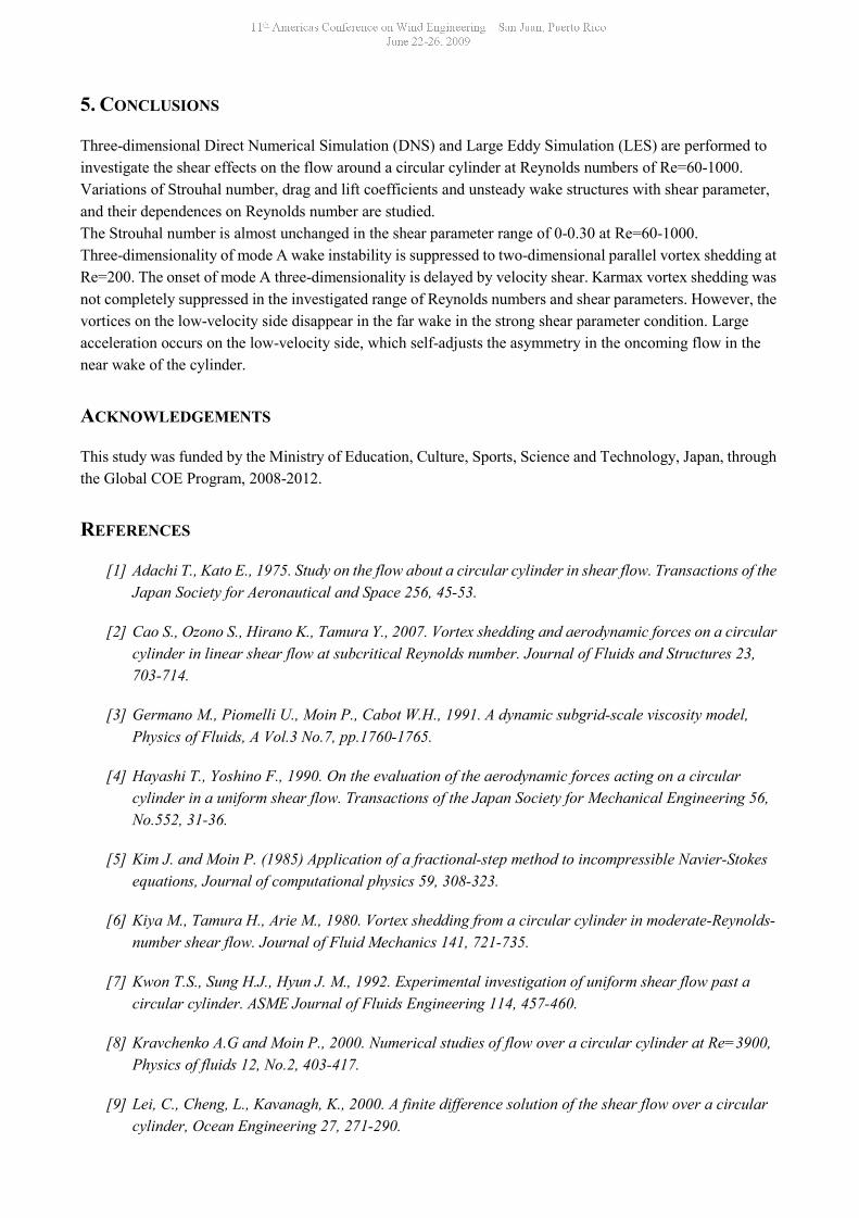
direction is observed. However, its relation to shear parameter or vortex shedding behavior is unknown.Compared to Re=200, due to the original complication of the spanwise structure at high Reynolds number, wecould not observe a distinct phenomenon of suppression of three dimensionality at Re=1000 (Fig.8a-8d).
(b) Results of past studies (----: Kiya et al., 1980;:Lei at al., 2000; : Cao et. al., 2007; : Sumner
and Akosile, 2003)
0 0.1 0.2 0.3
0.15
0.2
0.25
β
S t Re = 600
Re = 200
Re = 200
Re = 600
Re = 3.6× 10⁴
Re = 4× 10⁴~ 9× 10⁴
0 0.1 0.2 0.30.1
0.15
0.2
0.25
β
S t
(a) Results of present simulation (○: Re=60; ●: Re=150;: Re=200; ▲: Re=500; : Re=1000)
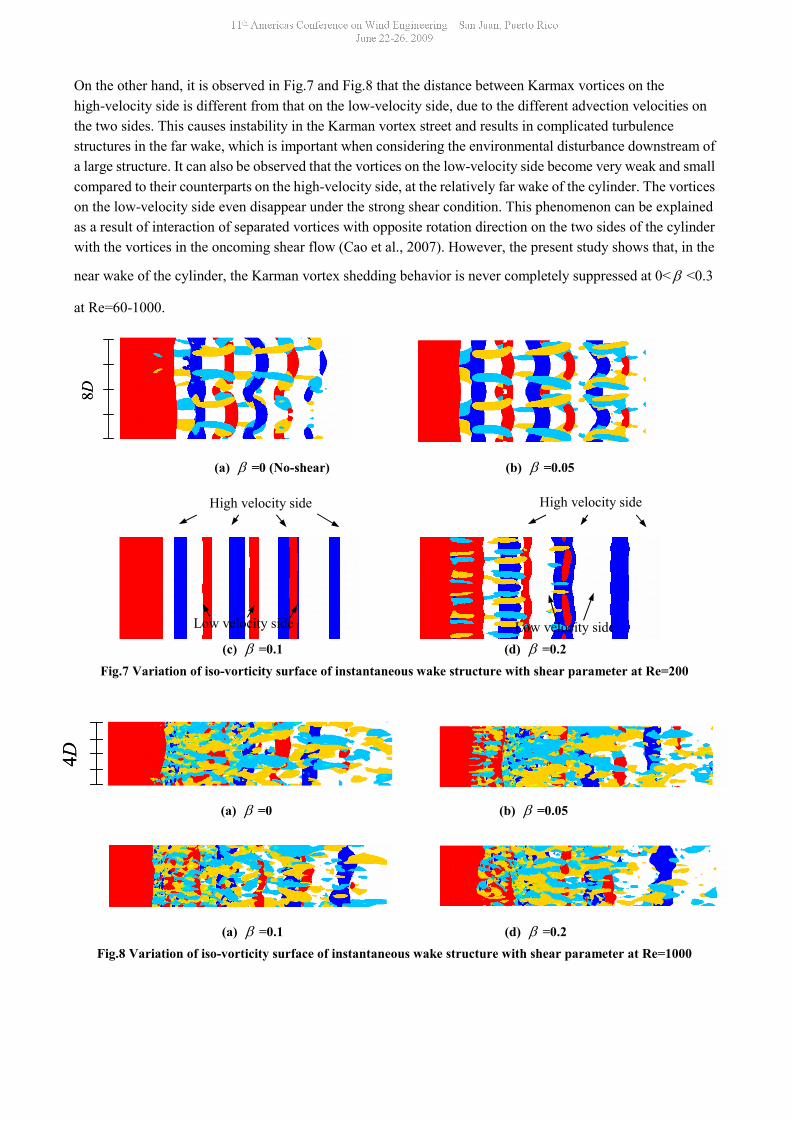
On the other hand, it is observed in Fig.7 and Fig.8 that the distance between Karmax vortices on thehigh-velocity side is different from that on the low-velocity side, due to the different advection velocities onthe two sides. This causes instability in the Karman vortex street and results in complicated turbulencestructures in the far wake, which is important when considering the environmental disturbance downstream ofa large structure. It can also be observed that the vortices on the low-velocity side become very weak and smallcompared to their counterparts on the high-velocity side, at the relatively far wake of the cylinder. The vorticeson the low-velocity side even disappear under the strong shear condition. This phenomenon can be explainedas a result of interaction of separated vortices with opposite rotation direction on the two sides of the cylinderwith the vortices in the oncoming shear flow (Cao et al., 2007). However, the present study shows that, in the
near wake of the cylinder, the Karman vortex shedding behavior is never completely suppressed at 0< <0.3
at Re=60-1000.
(a) =0 (No-shear) (b) =0.05
(c) =0.1 (d) =0.2Fig.7 Variation of iso-vorticity surface of instantaneous wake structure with shear parameter at Re=200
(a) =0 (b) =0.05
(a) =0.1 (d) =0.2Fig.8 Variation of iso-vorticity surface of instantaneous wake structure with shear parameter at Re=1000
8D8D
High velocity sideHigh velocity side
Low velocity sideLow velocity side
4D4D
5. CONCLUSIONS
Three-dimensional Direct Numerical Simulation (DNS) and Large Eddy Simulation (LES) are performed toinvestigate the shear effects on the flow around a circular cylinder at Reynolds numbers of Re=60-1000.Variations of Strouhal number, drag and lift coefficients and unsteady wake structures with shear parameter,and their dependences on Reynolds number are studied.The Strouhal number is almost unchanged in the shear parameter range of 0-0.30 at Re=60-1000.Three-dimensionality of mode A wake instability is suppressed to two-dimensional parallel vortex shedding atRe=200. The onset of mode A three-dimensionality is delayed by velocity shear. Karmax vortex shedding wasnot completely suppressed in the investigated range of Reynolds numbers and shear parameters. However, thevortices on the low-velocity side disappear in the far wake in the strong shear parameter condition. Largeacceleration occurs on the low-velocity side, which self-adjusts the asymmetry in the oncoming flow in thenear wake of the cylinder.
ACKNOWLEDGEMENTS
This study was funded by the Ministry of Education, Culture, Sports, Science and Technology, Japan, throughthe Global COE Program, 2008-2012.
REFERENCES
[1] Adachi T., Kato E., 1975. Study on the flow about a circular cylinder in shear flow. Transactions of theJapan Society for Aeronautical and Space 256, 45-53.
[2] Cao S., Ozono S., Hirano K., Tamura Y., 2007. Vortex shedding and aerodynamic forces on a circularcylinder in linear shear flow at subcritical Reynolds number. Journal of Fluids and Structures 23,703-714.
[3] Germano M., Piomelli U., Moin P., Cabot W.H., 1991. A dynamic subgrid-scale viscosity model,Physics of Fluids, A Vol.3 No.7, pp.1760-1765.
[4] Hayashi T., Yoshino F., 1990. On the evaluation of the aerodynamic forces acting on a circularcylinder in a uniform shear flow. Transactions of the Japan Society for Mechanical Engineering 56,No.552, 31-36.
[5] Kim J. and Moin P. (1985) Application of a fractional-step method to incompressible Navier-Stokesequations, Journal of computational physics 59, 308-323.
[6] Kiya M., Tamura H., Arie M., 1980. Vortex shedding from a circular cylinder in moderate-Reynolds-number shear flow. Journal of Fluid Mechanics 141, 721-735.
[7] Kwon T.S., Sung H.J., Hyun J. M., 1992. Experimental investigation of uniform shear flow past acircular cylinder. ASME Journal of Fluids Engineering 114, 457-460.
[8] Kravchenko A.G and Moin P., 2000. Numerical studies of flow over a circular cylinder at Re=3900,Physics of fluids 12, No.2, 403-417.
[9] Lei, C., Cheng, L., Kavanagh, K., 2000. A finite difference solution of the shear flow over a circularcylinder, Ocean Engineering 27, 271-290.
[10] Lilly D.K., 1992. A proposed modification of the Germano subgrid-scale closure model, Physics ofFluids, A. Vol.4 No.4, pp.633-635.
[11] Persillon H, Braza M. Physical analysis of the transition to turbulence in the wake of a circularcylinder by three-dimensional Navier-Stokes simulation. Journal of Fluids Mechanics 1998; 365:23-88.
[12] Sumner D., Akosile O.O, 2003. On uniform planar shear flow around a circular cylinder atsubcritical Reynolds number, Journal of Fluids and Structures 13, 309-338.
[13] Zang Y, Street R.L. and Koseff J.R., 1994. A non-staggered grid, fractional step method fortime-dependent incompressible Navier-Stokes equations in curvilinear coordinates, Journal ofComputational Physics 114, 18-33.
[14] Tamura H., Kiya M., Arie M., 1980. Numerical study of viscous shear flow past a circular cylinder.Transactions of the Japan Society for Mechanical Engineering 46, No.404, 555-564.
[15] Tamura T. and Kitagishi T., 2001. Application of the interpolation method in generalized coordinatesystem to wake flows around a circular cylinder, J. Struct. Constr. Eng., AIJ, 545, 27-34.
[16] Tamura T., 2008. Towards practical use of LES in wind engineering, Journal of Wind Engineeringand Industrial Aerodynamics, 96 (10-11), 1451-1471.
[17] Williamson C.H.K., 1996. Vortex dynamics in the cylinder wake, Annu. Rev. Fluid Mech. 28, 477.
[18] Zhang H.Q, Fey U., Noack B.R., 1995. On the transition of the cylinder wake, Phys. Fluids 7(4)779-794.