Embed Size (px)
Citation preview
Surveyor LC Pump Plus
Hardware Manual
60053-97120 Revision E January 2009
© 2009 Thermo Fisher Scientific Inc. All rights reserved.
Xcalibur is a registered trademark and Surveyor and ChromQuest are trademarks of Thermo Fisher Scientific Inc. in the United States.
Super Flangeless is a trademark of Upchurch Scientific. PEEK is a trademark of Vitrex PLC.
The following are registered trademarks in the United States and other countries: Windows is a registeredtrademark of Microsoft Corporation. Teflon is a registered trademark of E. I. du Pont de Nemours & Co.
Hastelloy is the registered trademark of Haynes International, Inc. in the United States and possibly other countries.
Thermo Fisher Scientific Inc. provides this document to its customers with a product purchase to use in the product operation. This document is copyright protected and any reproduction of the whole or any part of this document is strictly prohibited, except with the written authorization of Thermo Fisher Scientific Inc.
The contents of this document are subject to change without notice. All technical information in this document is for reference purposes only. System configurations and specifications in this document supersede all previous information received by the purchaser.
Thermo Fisher Scientific Inc. makes no representations that this document is complete, accurate or error-free and assumes no responsibility and will not be liable for any errors, omissions, damage or loss that might result from any use of this document, even if the information in the document is followed properly.
This document is not part of any sales contract between Thermo Fisher Scientific Inc. and a purchaser. This document shall in no way govern or modify any Terms and Conditions of Sale, which Terms and Conditions of Sale shall govern all conflicting information between the two documents.
Release history: Revision A April 2006, Revision B September 2006, Revision C November 2007, Revision D March 2008, Revision E January 2009
Firmware version: You can use the Surveyor Firmware Upgrade Utility to make sure that the firmware is compatible with the instrument control software.
For Research Use Only. Not regulated for medical or veterinary diagnostic use by U.S. Federal Drug Administration or other competent authorities.
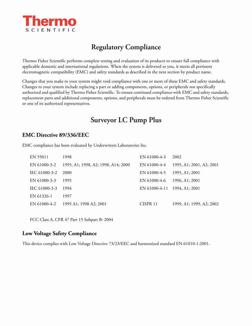
Regulatory Compliance
Thermo Fisher Scientific performs complete testing and evaluation of its products to ensure full compliance with applicable domestic and international regulations. When the system is delivered to you, it meets all pertinent electromagnetic compatibility (EMC) and safety standards as described in the next section by product name.
Changes that you make to your system might void compliance with one or more of these EMC and safety standards. Changes to your system include replacing a part or adding components, options, or peripherals not specifically authorized and qualified by Thermo Fisher Scientific. To ensure continued compliance with EMC and safety standards, replacement parts and additional components, options, and peripherals must be ordered from Thermo Fisher Scientific or one of its authorized representatives.
Surveyor LC Pump Plus
EMC Directive 89/336/EEC
EMC compliance has been evaluated by Underwriters Laboratories Inc.
Low Voltage Safety Compliance
This device complies with Low Voltage Directive 73/23/EEC and harmonized standard EN 61010-1:2001.
EN 55011 1998 EN 61000-4-3 2002
EN 61000-3-2 1995, A1; 1998, A2; 1998, A14; 2000 EN 61000-4-4 1995, A1; 2001, A2; 2001
IEC 61000-3-2 2000 EN 61000-4-5 1995, A1; 2001
EN 61000-3-3 1995 EN 61000-4-6 1996, A1; 2001
IEC 61000-3-3 1994 EN 61000-4-11 1994, A1; 2001
EN 61326-1 1997
EN 61000-4-2 1995 A1; 1998 A2; 2001 CISPR 11 1999, A1; 1999, A2; 2002
FCC Class A, CFR 47 Part 15 Subpart B: 2004

FCC Compliance Statement
Notice on Lifting and Handling ofThermo Fisher Scientific Instruments
For your safety, and in compliance with international regulations, the physical handling of this Thermo Fisher Scientific instrument requires a team effort to lift and/or move the instrument. This instrument is too heavy and/or bulky for one person alone to handle safely.
Notice on the Proper Use ofThermo Fisher Scientific Instruments
In compliance with international regulations: Use of this instrument in a manner not specified by Thermo Fisher Scientific could impair any protection provided by the instrument.
Notice on the Susceptibility to Electromagnetic Transmissions
Your instrument is designed to work in a controlled electromagnetic environment. Do not use radio frequency transmitters, such as mobile phones, in close proximity to the instrument.
For manufacturing location, see the label on the instrument.
THIS DEVICE COMPLIES WITH PART 15 OF THE FCC RULES. OPERATION IS SUBJECT TO THE FOLLOWING TWO CONDITIONS: (1) THIS DEVICE MAY NOT CAUSE HARMFUL INTERFERENCE, AND (2) THIS DEVICE MUST ACCEPT ANY INTERFERENCE RECEIVED, INCLUDING INTERFERENCE THAT MAY CAUSE UNDESIRED OPERATION.
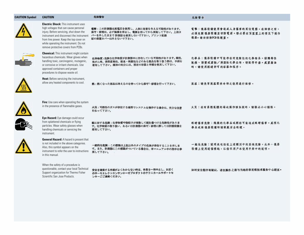
CAUTION Read and understand the various precautionary notes, signs, and symbols contained inside this manual pertaining to the safe use and operation of this product before using the device.

WEEE Compliance
This product is required to comply with the European Union’s Waste Electrical & Electronic Equipment (WEEE) Directive 2002/96/EC. It is marked with the following symbol:
Thermo Fisher Scientific has contracted with one or more recycling or disposal companies in each European Union (EU) Member State, and these companies should dispose of or recycle this product. See www.thermo.com/WEEERoHS for further information on Thermo Fisher Scientific’s compliance with these Directives and the recyclers in your country.
WEEE Konformität
Dieses Produkt muss die EU Waste Electrical & Electronic Equipment (WEEE) Richtlinie 2002/96/EC erfüllen. Das Produkt ist durch folgendes Symbol gekennzeichnet:
Thermo Fisher Scientific hat Vereinbarungen mit Verwertungs-/Entsorgungsfirmen in allen EU-Mitgliedsstaaten getroffen, damit dieses Produkt durch diese Firmen wiederverwertet oder entsorgt werden kann. Mehr Information über die Einhaltung dieser Anweisungen durch Thermo Fisher Scientific, über die Verwerter, und weitere Hinweise, die nützlich sind, um die Produkte zu identifizieren, die unter diese RoHS Anweisung fallen, finden sie unter www.thermo.com/WEEERoHS.
Conformité DEEE
Ce produit doit être conforme à la directive européenne (2002/96/EC) des Déchets d'Equipements Electriques et Electroniques (DEEE). Il est marqué par le symbole suivant:
Thermo Fisher Scientific s'est associé avec une ou plusieurs compagnies de recyclage dans chaque état membre de l’union européenne et ce produit devrait être collecté ou recyclé par celles-ci. Davantage d'informations sur la conformité de Thermo Fisher Scientific à ces directives, les recycleurs dans votre pays et les informations sur les produits Thermo Fisher Scientific qui peuvent aider la détection des substances sujettes à la directive RoHS sont disponibles sur www.thermo.com/WEEERoHS.
AVVERTENZA
trumento s de ntes de
al arse y limentacion nto sin sus o remueva
s tarjetas
Shock da folgorazione. L’apparecchio è alimentato da corrente ad alta tensione che puo provocare lesioni fisiche. Prima di effettuare qualsiasi intervento di manutenzione occorre spegnere ed isolare l’apparecchio dalla linea elettrica. Non attivare lo strumento senza lo schermo superiore. Non togliere i coperchi a protezione dalle schede di circuito stampato (PCB).
e contener . Utilice quimicos nos o cipientes y a
Prodotti chimici. Possibile presenza di sostanze chimiche pericolose nell’apparecchio. Indossare dei guanti per maneggiare prodotti chimici tossici, cancerogeni, mutageni, o corrosivi/irritanti. Utilizzare contenitori aprovo e seguire la procedura indicata per lo smaltimento dei residui di olio.
que lop de efectuar
Calore. Attendere che i componenti riscaldati si raffreddino prima di effetturare l’intervento di manutenzione.
ar el
Incendio. Adottare le dovute precauzioni quando si usa il sistema in presenza di gas infiammabili.
icaduras de s que usar teojos tos .
Pericolo per la vista. Gli schizzi di prodotti chimici o delle particelle presenti nell’aria potrebbero causare danni alla vista. Indossare occhiali protettivi quando si maneggiano prodotti chimici o si effettuano interventi di manutenzione sull’apparecchio.
e existe un gorias én se utiliza l usuario a n este
Pericolo generico. Pericolo non compreso tra le precedenti categorie. Questo simbolo è utilizzato inoltre sull’apparecchio per segnalare all’utente di consultare le istruzioni descritte nel presente manuale.
de un tes de o con la local para r Scientific
Quando e in dubbio la misura di sicurezza per una procedura, prima di continuare, si prega di mettersi in contatto con il Servizio di Assistenza Tecnica locale per i prodotti di Thermo Fisher Scientific San Jose.
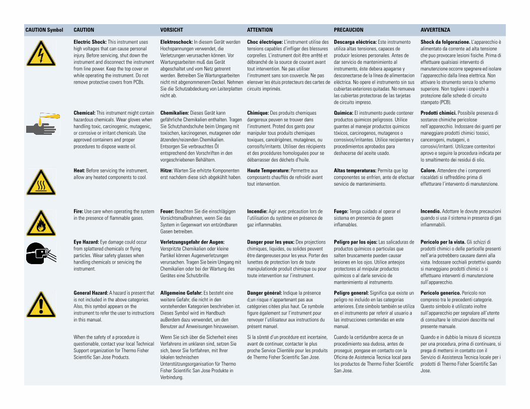
CAUTION Symbol CAUTION VORSICHT ATTENTION PRECAUCION
Electric Shock: This instrument uses high voltages that can cause personal injury. Before servicing, shut down the instrument and disconnect the instrument from line power. Keep the top cover on while operating the instrument. Do not remove protective covers from PCBs.
Elektroschock: In diesem Gerät werden Hochspannungen verwendet, die Verletzungen verursachen können. Vor Wartungsarbeiten muß das Gerät abgeschaltet und vom Netz getrennt werden. Betreiben Sie Wartungsarbeiten nicht mit abgenommenem Deckel. Nehmen Sie die Schutzabdeckung von Leiterplatten nicht ab.
Choc électrique: L’instrument utilise des tensions capables d’infliger des blessures corprelles. L’instrument doit être arrêté et débranché de la source de courant avant tout intervention. Ne pas utiliser l’instrument sans son couvercle. Ne pas elensver les étuis protecteurs des cartes de circuits imprimés.
Descarga eléctrica: Este insutiliza altas tensiones, capaceproducir lesiones personales. Adar servicio de mantenimientoinstrumento, éste debera apagdesconectarse de la línea de aeléctrica. No opere el instrumecubiertas exteriores quitadas. Nlas cubiertas protectoras de lade circuito impreso.
Chemical: This instrument might contain hazardous chemicals. Wear gloves when handling toxic, carcinogenic, mutagenic, or corrosive or irritant chemicals. Use approved containers and proper procedures to dispose waste oil.
Chemikalien: Dieses Gerät kann gefährliche Chemikalien enthalten. Tragen Sie Schutzhandschuhe beim Umgang mit toxischen, karzinogenen, mutagenen oder ätzenden/reizenden Chemikalien. Entsorgen Sie verbrauchtes Öl entsprechend den Vorschriften in den vorgeschriebenen Behältern.
Chimique: Des produits chemiques dangereux peuven se trouver dans l’instrument. Proted dos gants pour manipuler tous produits chemiques toxiques, cancérigènes, mutagènes, ou corrosifs/irritants. Utiliser des récipients et des procédures homologuées pour se débarrasser des déchets d’huile.
Química: El instrumento puedproductos quimicos peligrososguantes al manejar productos tóxicos, carcinogenos, mutagecorrosivos/irritantes. Utilice reprocedimientos aprobados pardeshacerse del aceite usado.
Heat: Before servicing the instrument, allow any heated components to cool.
Hitze: Warten Sie erhitzte Komponenten erst nachdem diese sich abgekühlt haben.
Haute Temperature: Permettre aux composants chauffés de refroidir avant tout intervention.
Altas temperaturas: Permitacomponentes se enfríen, ante servicio de mantenimiento.
Fire: Use care when operating the system in the presence of flammable gases.
Feuer: Beachten Sie die einschlägigen VorsichtsmaBnahmen, wenn Sie das System in Gegenwart von entzündbaren Gasen betreiben.
Incendie: Agir avec précaution lors de l’utilisation du système en présence de gaz inflammables.
Fuego: Tenga cuidado al opersistema en presencia de gasesinflamables.
Eye Hazard: Eye damage could occur from splattered chemicals or flying particles. Wear safety glasses when handling chemicals or servicing the instrument.
Verletzungsgefahr der Augen: Verspritzte Chemikalien oder kleine Partikel können Augenverletzungen verursachen. Tragen Sie beim Umgang mit Chemikalien oder bei der Wartung des Gerätes eine Schutzbrille.
Danger pour les yeux: Dex projections chimiques, liquides, ou solides peuvent être dangereuses pour les yeux. Porter des lunettes de protection lors de toute manipulationde produit chimique ou pour toute intervention sur l’instrument.
Peligro par los ojos: Las salproductos químicos o particulasalten bruscamente pueden calesiones en los ojos. Utilice anprotectores al mnipular producquímicos o al darle servicio demantenimiento al instrumento
General Hazard: A hazard is present that is not included in the above categories. Also, this symbol appears on the instrument to refer the user to instructions in this manual.
Allgemeine Gefahr: Es besteht eine weitere Gefahr, die nicht in den vorstehenden Kategorien beschrieben ist. Dieses Symbol wird im Handbuch auBerdem dazu verwendet, um den Benutzer auf Anweisungen hinzuweisen.
Danger général: Indique la présence d;un risque n’appartenant pas aux catégories citées plus haut. Ce symbole figure également sur l’instrument pour renvoyer l’utilisateur aux instructions du présent manuel.
Peligro general: Significa qupeligro no incluido en las cateanteriores. Este simbolo tambien el instrumento par referir alas instrucciones contenidas emanual.
When the safety of a procedure is questionable, contact your local Technical Support organization for Thermo Fisher Scientific San Jose Products.
Wenn Sie sich über die Sicherheit eines Verfahrens im unklaren sind, setzen Sie sich, bevor Sie fortfahren, mit Ihrer lokalen technischen Unterstützungsorganisation für Thermo Fisher Scientific San Jose Produkte in Verbindung.
Si la sûreté d’un procédure est incertaine, avant de continuer, contacter le plus proche Service Clientèle pour les produits de Thermo Fisher Scientific San Jose.
Cuando la certidumbre acerca procedimiento sea dudosa, anproseguir, pongase en contactOficina de Asistencia Tecnica los productos de Thermo FisheSan Jose.
CAUTION Symbol CAUTION
Electric Shock: This instrument uses high voltages that can cause personal injury. Before servicing, shut down the instrument and disconnect the instrument from line power. Keep the top cover on while operating the instrument. Do not remove protective covers from PCBs.
Chemical: This instrument might contain hazardous chemicals. Wear gloves when handling toxic, carcinogenic, mutagenic, or corrosive or irritant chemicals. Use approved containers and proper procedures to dispose waste oil.
Heat: Before servicing the instrument, allow any heated components to cool.
Fire: Use care when operating the system in the presence of flammable gases.
Eye Hazard: Eye damage could occur from splattered chemicals or flying particles. Wear safety glasses when handling chemicals or servicing the instrument.
General Hazard: A hazard is present that is not included in the above categories. Also, this symbol appears on the instrument to refer the user to instructions in this manual.
When the safety of a procedure is questionable, contact your local Technical Support organization for Thermo Fisher Scientific San Jose Products.
C
Contents
Preface . . . . . . . . . . . . . . . . . . . . . . . . . . . . . . . . . . . . . . . . . . . . . . . . . . . . . . . . . . . . .xiiiRelated Documentation . . . . . . . . . . . . . . . . . . . . . . . . . . . . . . . . . . . . . . . . . .xiiiSafety and Special Notices . . . . . . . . . . . . . . . . . . . . . . . . . . . . . . . . . . . . . . . .xiiiGood Laboratory Practices . . . . . . . . . . . . . . . . . . . . . . . . . . . . . . . . . . . . . . . .xivContacting Us . . . . . . . . . . . . . . . . . . . . . . . . . . . . . . . . . . . . . . . . . . . . . . . . .xvi
Chapter 1 Introduction . . . . . . . . . . . . . . . . . . . . . . . . . . . . . . . . . . . . . . . . . . . . . . . . . . . . . . . . . . .1Functional Description . . . . . . . . . . . . . . . . . . . . . . . . . . . . . . . . . . . . . . . . . . . . 2
Vacuum Degasser Assembly. . . . . . . . . . . . . . . . . . . . . . . . . . . . . . . . . . . . . . . 3Solvent Proportioning Assembly . . . . . . . . . . . . . . . . . . . . . . . . . . . . . . . . . . . 3Pump Head Assemblies . . . . . . . . . . . . . . . . . . . . . . . . . . . . . . . . . . . . . . . . . . 3Purge Manifold Assembly . . . . . . . . . . . . . . . . . . . . . . . . . . . . . . . . . . . . . . . . 9Pulse Dampening Assembly. . . . . . . . . . . . . . . . . . . . . . . . . . . . . . . . . . . . . . 10
Status LEDs . . . . . . . . . . . . . . . . . . . . . . . . . . . . . . . . . . . . . . . . . . . . . . . . . . . 10Flow Control. . . . . . . . . . . . . . . . . . . . . . . . . . . . . . . . . . . . . . . . . . . . . . . . . . . 12Specifications. . . . . . . . . . . . . . . . . . . . . . . . . . . . . . . . . . . . . . . . . . . . . . . . . . . 15
Chapter 2 Installation . . . . . . . . . . . . . . . . . . . . . . . . . . . . . . . . . . . . . . . . . . . . . . . . . . . . . . . . . . .17Installation Checklist. . . . . . . . . . . . . . . . . . . . . . . . . . . . . . . . . . . . . . . . . . . . . 18Unpacking and Inspecting the Instrument . . . . . . . . . . . . . . . . . . . . . . . . . . . . 18Making Initial Instrument Preparations. . . . . . . . . . . . . . . . . . . . . . . . . . . . . . . 19Connecting the Back Panel Cables . . . . . . . . . . . . . . . . . . . . . . . . . . . . . . . . . . 19
System Synchronization Cable. . . . . . . . . . . . . . . . . . . . . . . . . . . . . . . . . . . . 20Ethernet Cable . . . . . . . . . . . . . . . . . . . . . . . . . . . . . . . . . . . . . . . . . . . . . . . 20Unit ID Settings . . . . . . . . . . . . . . . . . . . . . . . . . . . . . . . . . . . . . . . . . . . . . . 20
Connecting the Solvent Lines . . . . . . . . . . . . . . . . . . . . . . . . . . . . . . . . . . . . . . 21Solvent Inlet Lines. . . . . . . . . . . . . . . . . . . . . . . . . . . . . . . . . . . . . . . . . . . . . 21Solvent Outlet Tubing . . . . . . . . . . . . . . . . . . . . . . . . . . . . . . . . . . . . . . . . . 25
Powering On the Pump for the First Time . . . . . . . . . . . . . . . . . . . . . . . . . . . . 26Calibrating the Surveyor LC Pump Plus . . . . . . . . . . . . . . . . . . . . . . . . . . . . . . 26
Chapter 3 Data System Instrument Configuration . . . . . . . . . . . . . . . . . . . . . . . . . . . . . . . . . . .27Adding the Surveyor LC Pump Plus to the ChromQuest Configuration . . . . . . 27
Configuring the Surveyor LC Pump Plus Device Driver . . . . . . . . . . . . . . . . 28Configuring the Signal Polarities for the Surveyor AS in ChromQuest . . . . . 33
Thermo Scientific Surveyor LC Pump Plus Hardware Manual ix
Contents
x
Adding the Surveyor LC Pump to the Xcalibur Instrument Configuration . . . . 34Configuring the Surveyor LC Pump . . . . . . . . . . . . . . . . . . . . . . . . . . . . . . . 34Configuring the Signal Polarities for the Surveyor AS . . . . . . . . . . . . . . . . . . 35
Chapter 4 Maintenance . . . . . . . . . . . . . . . . . . . . . . . . . . . . . . . . . . . . . . . . . . . . . . . . . . . . . . . . .37Maintenance Schedule. . . . . . . . . . . . . . . . . . . . . . . . . . . . . . . . . . . . . . . . . . . . 38Maintenance Page in ChromQuest . . . . . . . . . . . . . . . . . . . . . . . . . . . . . . . . . . 39
Opening the Maintenance Page in ChromQuest . . . . . . . . . . . . . . . . . . . . . . 39Recording Maintenance in ChromQuest . . . . . . . . . . . . . . . . . . . . . . . . . . . . 40Setting the Pistons to the Maintenance Position from ChromQuest . . . . . . . 41
Maintenance Page in Xcalibur . . . . . . . . . . . . . . . . . . . . . . . . . . . . . . . . . . . . . . 41Opening the Maintenance Page in Xcalibur . . . . . . . . . . . . . . . . . . . . . . . . . 42Recording Maintenance in Xcalibur . . . . . . . . . . . . . . . . . . . . . . . . . . . . . . . 42Setting the Pistons to the Maintenance Position from Xcalibur . . . . . . . . . . . 43
Rinsing the Pistons . . . . . . . . . . . . . . . . . . . . . . . . . . . . . . . . . . . . . . . . . . . . . . 43Cleaning the Check Valves . . . . . . . . . . . . . . . . . . . . . . . . . . . . . . . . . . . . . . . . 45
Cleaning the Check Valves with Isopropyl Alcohol . . . . . . . . . . . . . . . . . . . . 46Removing the Check Valves . . . . . . . . . . . . . . . . . . . . . . . . . . . . . . . . . . . . . 47Sonicating the Check Valves . . . . . . . . . . . . . . . . . . . . . . . . . . . . . . . . . . . . . 49Reinstalling the Check Valves . . . . . . . . . . . . . . . . . . . . . . . . . . . . . . . . . . . . 49
Maintaining the Pump Head Assemblies . . . . . . . . . . . . . . . . . . . . . . . . . . . . . . 50Replacing a Piston Seal . . . . . . . . . . . . . . . . . . . . . . . . . . . . . . . . . . . . . . . . . 50Replacing the Wash Seals . . . . . . . . . . . . . . . . . . . . . . . . . . . . . . . . . . . . . . . 58Cleaning and Replacing a Piston . . . . . . . . . . . . . . . . . . . . . . . . . . . . . . . . . . 61
Replacing the Line Filter Frit. . . . . . . . . . . . . . . . . . . . . . . . . . . . . . . . . . . . . . . 64Replacing the Solvent Reservoir Filter . . . . . . . . . . . . . . . . . . . . . . . . . . . . . . . . 66Purging Air from the Solvent Lines or the Pump Heads . . . . . . . . . . . . . . . . . . 67
Purging a Solvent Line Using ChromQuest. . . . . . . . . . . . . . . . . . . . . . . . . . 67Purging a Solvent Line Using Xcalibur . . . . . . . . . . . . . . . . . . . . . . . . . . . . . 69
Replacing the Drain Valve Knob O-Ring . . . . . . . . . . . . . . . . . . . . . . . . . . . . . 70Replacing the Fuses . . . . . . . . . . . . . . . . . . . . . . . . . . . . . . . . . . . . . . . . . . . . . . 71
Chapter 5 Diagnostic Tests and Calibration Procedures. . . . . . . . . . . . . . . . . . . . . . . . . . . . .73Flow Rate Accuracy Check . . . . . . . . . . . . . . . . . . . . . . . . . . . . . . . . . . . . . . . . 74Pressure Pulsation Check. . . . . . . . . . . . . . . . . . . . . . . . . . . . . . . . . . . . . . . . . . 76
Checking the Pressure Pulsation of the LC Pump . . . . . . . . . . . . . . . . . . . . . 76Troubleshooting the Cause of Excessive Pressure Variation . . . . . . . . . . . . . 76
Proportioning Accuracy Check . . . . . . . . . . . . . . . . . . . . . . . . . . . . . . . . . . . . . 77Proportioning Accuracy Test—Preparation . . . . . . . . . . . . . . . . . . . . . . . . . . 78Testing Proportioning Accuracy . . . . . . . . . . . . . . . . . . . . . . . . . . . . . . . . . . 79Analyzing the Results of the Test . . . . . . . . . . . . . . . . . . . . . . . . . . . . . . . . . . 80
Gradient Delay Volume Check . . . . . . . . . . . . . . . . . . . . . . . . . . . . . . . . . . . . . 82
Surveyor LC Pump Plus Hardware Manual Thermo Scientific
Contents
Calibration . . . . . . . . . . . . . . . . . . . . . . . . . . . . . . . . . . . . . . . . . . . . . . . . . . . . 84Compressibility . . . . . . . . . . . . . . . . . . . . . . . . . . . . . . . . . . . . . . . . . . . . . . 84Pressure Recorder Full Scale . . . . . . . . . . . . . . . . . . . . . . . . . . . . . . . . . . . . . 86Flow Rate Adjustment (Alpha) . . . . . . . . . . . . . . . . . . . . . . . . . . . . . . . . . . . 87Pressure Sensor Adjustment. . . . . . . . . . . . . . . . . . . . . . . . . . . . . . . . . . . . . . 87Pressure Transducer Zero . . . . . . . . . . . . . . . . . . . . . . . . . . . . . . . . . . . . . . . 87
Chapter 6 Troubleshooting. . . . . . . . . . . . . . . . . . . . . . . . . . . . . . . . . . . . . . . . . . . . . . . . . . . . . . .89Troubleshooting Tips . . . . . . . . . . . . . . . . . . . . . . . . . . . . . . . . . . . . . . . . . . . . 89General System Troubleshooting. . . . . . . . . . . . . . . . . . . . . . . . . . . . . . . . . . . . 90LC Pump Troubleshooting Guide. . . . . . . . . . . . . . . . . . . . . . . . . . . . . . . . . . . 92Pump Pulsation . . . . . . . . . . . . . . . . . . . . . . . . . . . . . . . . . . . . . . . . . . . . . . . . . 93
Normal Pressure Pulsation. . . . . . . . . . . . . . . . . . . . . . . . . . . . . . . . . . . . . . . 93Abnormal Pressure Pulsation . . . . . . . . . . . . . . . . . . . . . . . . . . . . . . . . . . . . . 94
Baseline Noise at Low Pressures (Under 40 Bar) . . . . . . . . . . . . . . . . . . . . . . . . 94Insufficient Solvent Flow from the Pump Outlet. . . . . . . . . . . . . . . . . . . . . . . . 95
Pump Cavitation . . . . . . . . . . . . . . . . . . . . . . . . . . . . . . . . . . . . . . . . . . . . . . 95Blocked Proportioning Valve. . . . . . . . . . . . . . . . . . . . . . . . . . . . . . . . . . . . . 95Blocked Check Valve. . . . . . . . . . . . . . . . . . . . . . . . . . . . . . . . . . . . . . . . . . . 95
Irreproducible Retention Times . . . . . . . . . . . . . . . . . . . . . . . . . . . . . . . . . . . . 96
Chapter 7 Accessories and Replaceable Parts . . . . . . . . . . . . . . . . . . . . . . . . . . . . . . . . . . . . .97Surveyor LC Pump Accessory Kit . . . . . . . . . . . . . . . . . . . . . . . . . . . . . . . . . . . 98Replacement Parts Required for Routine Maintenance . . . . . . . . . . . . . . . . . . . 98Nonconsumable Replacement Parts. . . . . . . . . . . . . . . . . . . . . . . . . . . . . . . . . . 99Replacement Parts Required for Nonroutine Maintenance . . . . . . . . . . . . . . . . 99Solvent Interconnect Kit . . . . . . . . . . . . . . . . . . . . . . . . . . . . . . . . . . . . . . . . . 100Other Parts and Assemblies . . . . . . . . . . . . . . . . . . . . . . . . . . . . . . . . . . . . . . . 100
Appendix 8 Firmware. . . . . . . . . . . . . . . . . . . . . . . . . . . . . . . . . . . . . . . . . . . . . . . . . . . . . . . . . . . .101Copying the Firmware Files from the ChromQuest CD . . . . . . . . . . . . . . . . . 102Updating the Ethernet Firmware for the Surveyor LC Pump Plus . . . . . . . . . . 103
Preparing the Pump to Download the Communication Firmware. . . . . . . . 103Downloading Communication Firmware Files . . . . . . . . . . . . . . . . . . . . . . 104Returning the Pump to Normal Operation . . . . . . . . . . . . . . . . . . . . . . . . . 106
Updating the CPU Firmware for the Surveyor LC Pump Plus . . . . . . . . . . . . 107Preparing the Surveyor LC Pump Plus for a CPU Firmware Upgrade . . . . . 107Using the Flash ROM Update Utility to Update the CPU Firmware . . . . . 110
Index . . . . . . . . . . . . . . . . . . . . . . . . . . . . . . . . . . . . . . . . . . . . . . . . . . . . . . . . . . . . . . .115
Thermo Scientific Surveyor LC Pump Plus Hardware Manual xi

P
Preface
This manual describes the maintenance procedures that you must perform to keep the Surveyor LC Pump Plus in optimal working condition.
Related DocumentationIn addition to this guide, Thermo Fisher Scientific provides the following documents for the Surveyor Plus product line:
• Surveyor Plus Preinstallation Requirements Guide
• Surveyor Plus Getting Connected Guide
• Surveyor Plus Getting Started with ChromQuest Guide
• Surveyor Plus Getting Started with Xcalibur Guide
The data system also provides Help.
Safety and Special NoticesMake sure you follow the precautionary statements presented in this guide. The safety and other special notices appear in boxes.
Safety and special notices include the following:
CAUTION Highlights hazards to humans, property, or the environment. Each CAUTION notice is accompanied by an appropriate CAUTION symbol.
IMPORTANT Highlights information necessary to prevent damage to software, loss of data, or invalid test results; or might contain information that is critical for optimal performance of the system.
Note Highlights information of general interest.
Thermo Scientific Surveyor LC Pump Plus Hardware Manual xiii
Preface
xiv
Good Laboratory PracticesTo obtain optimal performance from your LC system and to prevent personal injury or injury to the environment, do the following:
• Keep good records
• Read the manufacturers’ Material Safety Data Sheets for the chemicals being used in your laboratory
• Remove particulate matter from your samples before you inject them into the liquid chromatograph
• Use HPLC grade solvents
• Connect the drainage tubes from the pump, autosampler, and detector to an appropriate waste receptacle. Dispose of solvents as specified by local regulations.
Keep Good Records
To help identify and isolate problems with either your equipment or your methodology, keep good records of all system conditions (for example,% RSDs on retention times and peak areas, peak shape and resolution). At a minimum, keep a chromatogram of a typical sample and standard mixture, well documented with system conditions, for future reference. Careful comparison of retention times, peak shapes, peak sensitivity, and baseline noise can provide valuable clues to identifying and solving future problems.
Chemical Toxicity
Although the large volume of toxic and flammable solvents used and stored in laboratories can be quite dangerous, do not ignore the potential hazards posed by your samples. Take special care to read and follow all precautions that ensure proper ventilation, storage, handling, and disposal of both solvents and samples. Become familiar with the toxicity data and potential hazards associated with all chemicals by referring to the manufacturers’ Material Safety Data Sheets (MSDSs).
Sample Preparation
Always consider the solubility of your sample in the solvent/mobile phase. Sample precipitation can plug the column, tubing or flowcell causing flow restriction. This obstruction can result in irreparable damage to the system. To avoid damage caused by particulate matter, filter samples through 0.45 or 0.2 micron (or less) filters.
Tip Highlights helpful information that can make a task easier.
Surveyor LC Pump Plus Hardware Manual Thermo Scientific
Preface
T
Solvent Requirements
Many chemical manufacturers provide a line of high-purity or HPLC-grade reagents that are free of chemical impurities. Routine filtration of all solvents or eluents through a 0.45 or 0.2 micron (or less) fluorocarbon filter before placing them in the solvent reservoir significantly prolongs the life and effectiveness of the inlet filters, check valves and seals, injector, and column. Typically, HPLC-grade solvents do not require filtration.
Choose a mobile phase that is compatible with the sample and column you have selected for your separation. Remember that some solvents are corrosive to stainless steel.
Solvent Disposal
Make sure you have a solvent waste container or other kind of drain system available at or below the benchtop level. Most solvents have special disposal requirements and should not be disposed of directly down a drain. Follow all governmental regulations when disposing of any chemical.
High-pressure Systems and Leaks
LC systems operate at high pressures. Because liquids are not highly compressible they do not store much energy. Accordingly, there is little immediate danger from the high pressures in an LC system. However, if a leak occurs, correct it as soon as possible. Always wear eye and skin protection when operating or maintaining an LC system. Always shut down the system and return it to atmospheric pressure before attempting any maintenance.
hermo Scientific Surveyor LC Pump Plus Hardware Manual xv
Preface
xvi
Contacting UsThere are several ways to contact Thermo Fisher Scientific for the information you need.
To contact Technical Support
Find software updates and utilities to download at mssupport.thermo.com.
To contact Customer Service for ordering information
To copy manuals from the Internet
Go to mssupport.thermo.com and click Customer Manuals in the left margin of the window.
To suggest changes to documentation or to Help
• To provide us with comments about this document, click the link below. Thank you in advance for your help.
• Send an e-mail message to the Technical Publications Editor at [email protected].
Phone 800-532-4752Fax 561-688-8736E-mail [email protected] base www.thermokb.com
Phone 800-532-4752Fax 561-688-8731E-mail [email protected] site www.thermo.com/ms
Surveyor LC Pump Plus Hardware Manual Thermo Scientific
1
Introduction
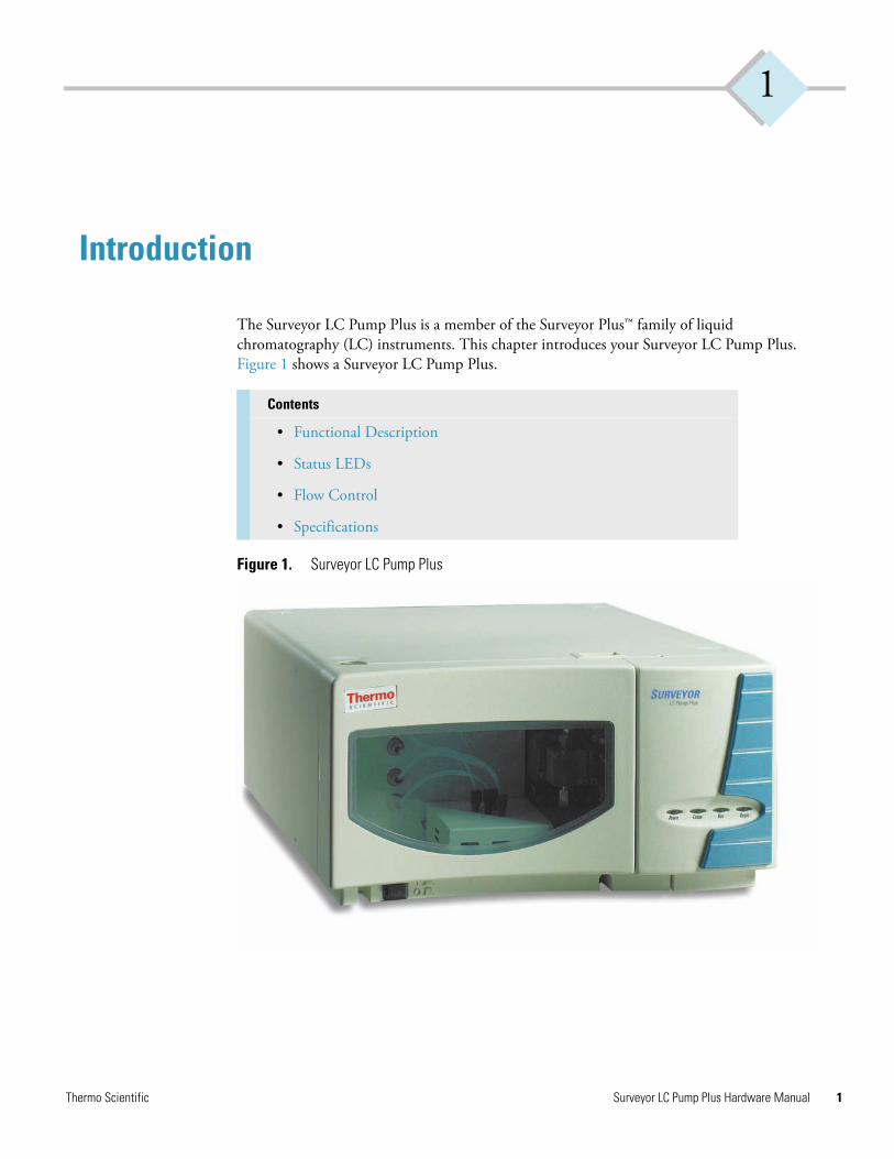
The Surveyor LC Pump Plus is a member of the Surveyor Plus™ family of liquid chromatography (LC) instruments. This chapter introduces your Surveyor LC Pump Plus. Figure 1 shows a Surveyor LC Pump Plus.
Figure 1. Surveyor LC Pump Plus
Contents
• Functional Description
• Status LEDs
• Flow Control
• Specifications
Thermo Scientific Surveyor LC Pump Plus Hardware Manual 1
1 IntroductionFunctional Description
2
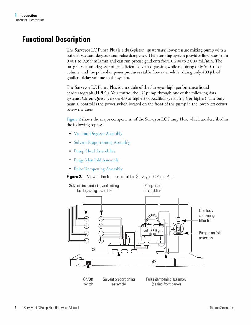
Functional DescriptionThe Surveyor LC Pump Plus is a dual-piston, quaternary, low-pressure mixing pump with a built-in vacuum degasser and pulse dampener. The pumping system provides flow rates from 0.001 to 9.999 mL/min and can run precise gradients from 0.200 to 2.000 mL/min. The integral vacuum degasser offers efficient solvent degassing while requiring only 500 μL of volume, and the pulse dampener produces stable flow rates while adding only 400 μL of gradient delay volume to the system.
The Surveyor LC Pump Plus is a module of the Surveyor high performance liquid chromatograph (HPLC). You control the LC pump through one of the following data systems: ChromQuest (version 4.0 or higher) or Xcalibur (version 1.4 or higher). The only manual control is the power switch located on the front of the pump in the lower-left corner below the door.
Figure 2 shows the major components of the Surveyor LC Pump Plus, which are described in the following topics:
• Vacuum Degasser Assembly
• Solvent Proportioning Assembly
• Pump Head Assemblies
• Purge Manifold Assembly
• Pulse Dampening Assembly
Figure 2. View of the front panel of the Surveyor LC Pump Plus
A
IN OUT
B
C
D
DRAIN
CLOSE OPEN
Solvent lines entering and exiting the degassing assembly
Pump head assemblies
Left Right
Line body containing filter frit
Purge manifold assembly
Pulse dampening assembly (behind front panel)
Solvent proportioning assembly
On/Off switch
Surveyor LC Pump Plus Hardware Manual Thermo Scientific
1 IntroductionFunctional Description
T
Vacuum Degasser Assembly
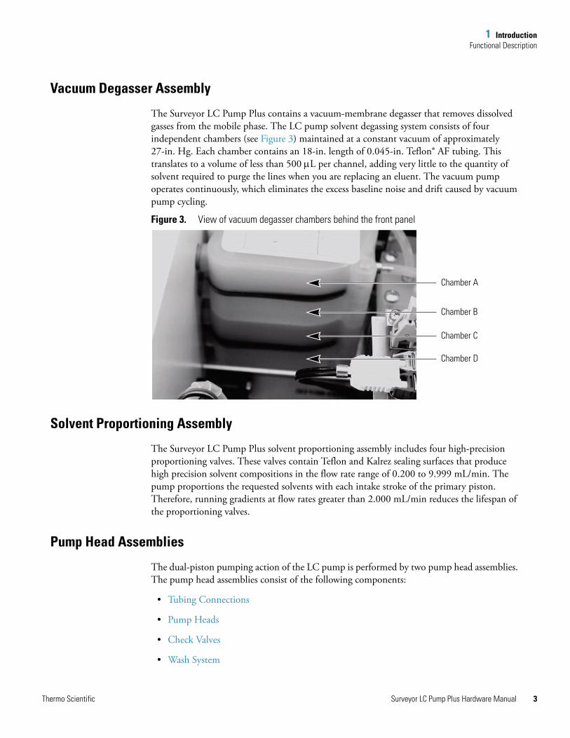
The Surveyor LC Pump Plus contains a vacuum-membrane degasser that removes dissolved gasses from the mobile phase. The LC pump solvent degassing system consists of four independent chambers (see Figure 3) maintained at a constant vacuum of approximately 27-in. Hg. Each chamber contains an 18-in. length of 0.045-in. Teflon® AF tubing. This translates to a volume of less than 500 μL per channel, adding very little to the quantity of solvent required to purge the lines when you are replacing an eluent. The vacuum pump operates continuously, which eliminates the excess baseline noise and drift caused by vacuum pump cycling.
Figure 3. View of vacuum degasser chambers behind the front panel
Solvent Proportioning Assembly
The Surveyor LC Pump Plus solvent proportioning assembly includes four high-precision proportioning valves. These valves contain Teflon and Kalrez sealing surfaces that produce high precision solvent compositions in the flow rate range of 0.200 to 9.999 mL/min. The pump proportions the requested solvents with each intake stroke of the primary piston. Therefore, running gradients at flow rates greater than 2.000 mL/min reduces the lifespan of the proportioning valves.
Pump Head Assemblies
The dual-piston pumping action of the LC pump is performed by two pump head assemblies. The pump head assemblies consist of the following components:
• Tubing Connections
• Pump Heads
• Check Valves
• Wash System
Chamber A
Chamber B
Chamber C
Chamber D
hermo Scientific Surveyor LC Pump Plus Hardware Manual 3
1 IntroductionFunctional Description
4
Tubing Connections
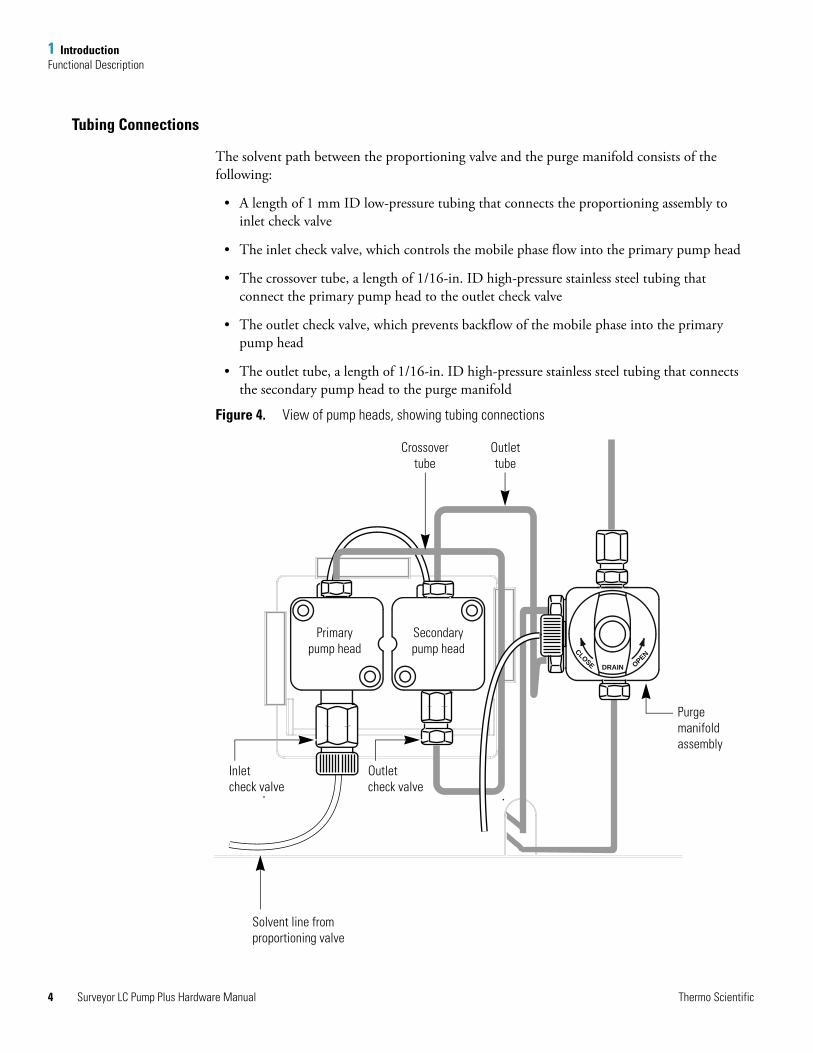
The solvent path between the proportioning valve and the purge manifold consists of the following:
• A length of 1 mm ID low-pressure tubing that connects the proportioning assembly to inlet check valve
• The inlet check valve, which controls the mobile phase flow into the primary pump head
• The crossover tube, a length of 1/16-in. ID high-pressure stainless steel tubing that connect the primary pump head to the outlet check valve
• The outlet check valve, which prevents backflow of the mobile phase into the primary pump head
• The outlet tube, a length of 1/16-in. ID high-pressure stainless steel tubing that connects the secondary pump head to the purge manifold
Figure 4. View of pump heads, showing tubing connections
DRAIN
CLOSE OPEN
Outlettube
Crossovertube
Purge manifold assembly
Secondary pump head
Primary pump head
Solvent line from proportioning valve
Inlet check valve
Outlet check valve
Surveyor LC Pump Plus Hardware Manual Thermo Scientific
1 IntroductionFunctional Description
T
Pump Heads
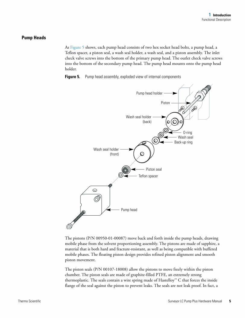
As Figure 5 shows, each pump head consists of two hex socket head bolts, a pump head, a Teflon spacer, a piston seal, a wash seal holder, a wash seal, and a piston assembly. The inlet check valve screws into the bottom of the primary pump head. The outlet check valve screws into the bottom of the secondary pump head. The pump head mounts onto the pump head holder.
Figure 5. Pump head assembly, exploded view of internal components
The pistons (P/N 00950-01-00087) move back and forth inside the pump heads, drawing mobile phase from the solvent proportioning assembly. The pistons are made of sapphire, a material that is both hard and fracture-resistant, as well as being compatible with buffered mobile phases. The floating piston design provides refined piston alignment and smooth piston movement.
The piston seals (P/N 00107-18008) allow the pistons to move freely within the piston chamber. The piston seals are made of graphite-filled PTFE, an extremely strong thermoplastic. The seals contain a wire spring made of Hastelloy™ C that forces the inside flange of the seal against the piston to prevent leaks. The seals are not leak proof. In fact, a
Pump head holder
Teflon spacer
Piston seal
Back-up ringWash seal
O-ring
Piston
Wash seal holder(back)
Pump head
Wash seal holder(front)
hermo Scientific Surveyor LC Pump Plus Hardware Manual 5
1 IntroductionFunctional Description
6
small quantity of the mobile phase is required to wet the surface of the pistons and acts as a lubricant to reduce wear on the piston seals. Through continued use and over time, the seals degrade and must be replaced. Allowing the pump to run dry and neglecting to rinse the pump head assemblies after pumping buffered eluents shortens the lifespan of the seals.
The wash seals (P/N 00950-01-00084) act as backwash seals that prevent liquid from leaking out of the piston chambers onto the electronic drive components of the pump. They also provide better alignment of the piston. The wash seals are made of unpigmented polyethylene.
Check Valves
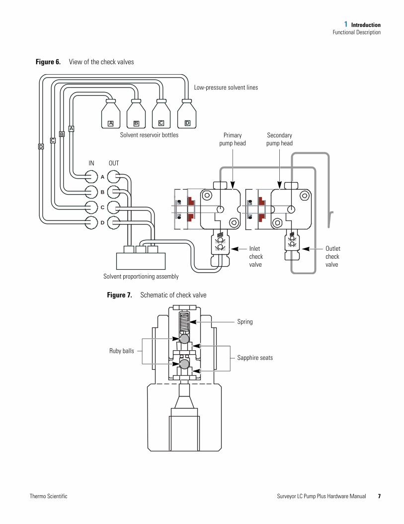
The inlet and outlet check valves are shut-off devices that allow the mobile phase to flow in only one direction (see Figure 6). Both check valves use two ruby balls, two sapphire seats, and a spring (see Figure 7). The ruby ball sits against the sapphire seat to prevent the flow of liquid by covering the aperture (hole) in the sapphire seat. The added spring prevents back flow even at low back pressures.
Check valves are actuated by changes in the pressure gradient (flow) across the valve. During the piston compression stroke, the pressure in the primary pump head increases. In response to the increased pressure, the balls in the outlet check valve are raised from their respective seats, allowing the mobile phase to pass through the aperture of each seat, around each ball, and out through the other side of the check valve into the crossover tube. Correspondingly, in response to the increased pressure in the primary pump head, the balls in the inlet check valve are pushed firmly onto their respective seats, sealing the aperture in each seat and thus preventing mobile phase from flowing back into the solvent proportioning assembly.
Because check valves must have a very precise fit between the balls and seat, particulate matter compromises the sealing action of the check valves and causes erratic flow rates.
Surveyor LC Pump Plus Hardware Manual Thermo Scientific
1 IntroductionFunctional Description
T
Figure 6. View of the check valves
Figure 7. Schematic of check valve
A
A B C
D
B
C
D
AB
C
D
Low-pressure solvent lines
Solvent reservoir bottles
IN OUT
Solvent proportioning assembly
Secondary pump head
Primary pump head
Outlet check valve
Inlet check valve
Ruby balls
Spring
Sapphire seats
hermo Scientific Surveyor LC Pump Plus Hardware Manual 7
1 IntroductionFunctional Description
8
Wash System
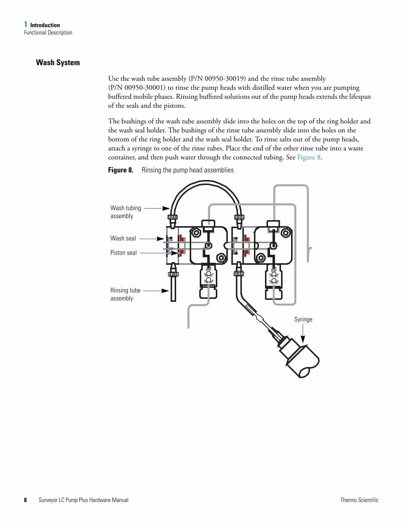
Use the wash tube assembly (P/N 00950-30019) and the rinse tube assembly (P/N 00950-30001) to rinse the pump heads with distilled water when you are pumping buffered mobile phases. Rinsing buffered solutions out of the pump heads extends the lifespan of the seals and the pistons.
The bushings of the wash tube assembly slide into the holes on the top of the ring holder and the wash seal holder. The bushings of the rinse tube assembly slide into the holes on the bottom of the ring holder and the wash seal holder. To rinse salts out of the pump heads, attach a syringe to one of the rinse tubes. Place the end of the other rinse tube into a waste container, and then push water through the connected tubing. See Figure 8.
Figure 8. Rinsing the pump head assemblies
Wash tubing assembly
Wash seal
Piston seal
Rinsing tube assembly
Syringe
Surveyor LC Pump Plus Hardware Manual Thermo Scientific
1 IntroductionFunctional Description
T
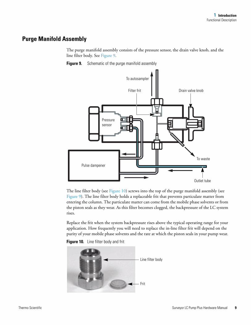
Purge Manifold Assembly
The purge manifold assembly consists of the pressure sensor, the drain valve knob, and the line filter body. See Figure 9.
Figure 9. Schematic of the purge manifold assembly
The line filter body (see Figure 10) screws into the top of the purge manifold assembly (see Figure 9). The line filter body holds a replaceable frit that prevents particulate matter from entering the column. The particulate matter can come from the mobile phase solvents or from the piston seals as they wear. As this filter becomes clogged, the backpressure of the LC system rises.
Replace the frit when the system backpressure rises above the typical operating range for your application. How frequently you will need to replace the in-line filter frit will depend on the purity of your mobile phase solvents and the rate at which the piston seals in your pump wear.
Figure 10. Line filter body and frit
Pulse dampener
Pressure sensor
To waste
To autosampler
Filter frit Drain valve knob
Outlet tube
Line filter body
Frit
hermo Scientific Surveyor LC Pump Plus Hardware Manual 9
1 IntroductionStatus LEDs
10
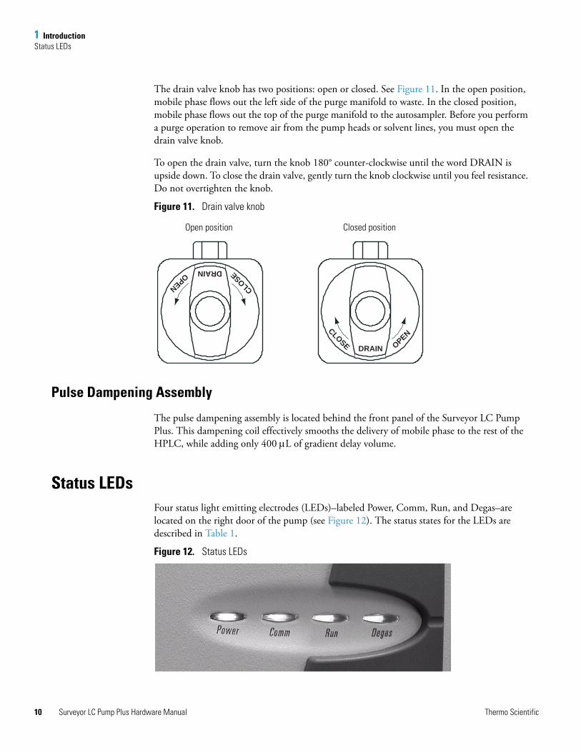
The drain valve knob has two positions: open or closed. See Figure 11. In the open position, mobile phase flows out the left side of the purge manifold to waste. In the closed position, mobile phase flows out the top of the purge manifold to the autosampler. Before you perform a purge operation to remove air from the pump heads or solvent lines, you must open the drain valve knob.
To open the drain valve, turn the knob 180° counter-clockwise until the word DRAIN is upside down. To close the drain valve, gently turn the knob clockwise until you feel resistance. Do not overtighten the knob.
Figure 11. Drain valve knob
Pulse Dampening Assembly
The pulse dampening assembly is located behind the front panel of the Surveyor LC Pump Plus. This dampening coil effectively smooths the delivery of mobile phase to the rest of the HPLC, while adding only 400 μL of gradient delay volume.
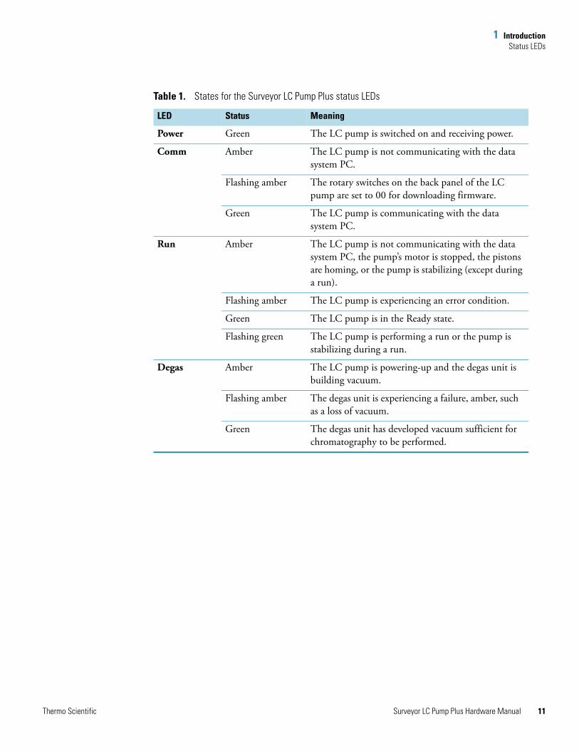
Status LEDsFour status light emitting electrodes (LEDs)–labeled Power, Comm, Run, and Degas–are located on the right door of the pump (see Figure 12). The status states for the LEDs are described in Table 1.
Figure 12. Status LEDs
DRAIN
CLOSE OPEN
DRAIN
CLOSEOPEN
Open position Closed position
Surveyor LC Pump Plus Hardware Manual Thermo Scientific
1 IntroductionStatus LEDs
T
Table 1. States for the Surveyor LC Pump Plus status LEDs
LED Status Meaning
Power Green The LC pump is switched on and receiving power.
Comm Amber The LC pump is not communicating with the data system PC.
Flashing amber The rotary switches on the back panel of the LC pump are set to 00 for downloading firmware.
Green The LC pump is communicating with the data system PC.
Run Amber The LC pump is not communicating with the data system PC, the pump’s motor is stopped, the pistons are homing, or the pump is stabilizing (except during a run).
Flashing amber The LC pump is experiencing an error condition.
Green The LC pump is in the Ready state.
Flashing green The LC pump is performing a run or the pump is stabilizing during a run.
Degas Amber The LC pump is powering-up and the degas unit is building vacuum.
Flashing amber The degas unit is experiencing a failure, amber, such as a loss of vacuum.
Green The degas unit has developed vacuum sufficient for chromatography to be performed.
hermo Scientific Surveyor LC Pump Plus Hardware Manual 11
1 IntroductionFlow Control
12
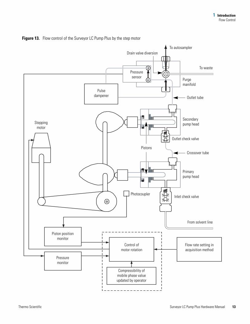
Flow ControlFigure 13 contains a schematic of the Surveyor LC Pump Plus flow control hardware.
A stepping motor that runs at 12800 pulses per revolution controls the flow rate of the mobile phase. The stepping motor drives a camshaft that is fitted with two cams. As the cams rotate, the cam-followers at the back of the pistons translate the rotary motion of the cams into linear motion. This linear motion moves the two parallel pistons back and forth inside the pump head.
The eccentric shape of the cams determines the stroke length of the pistons. The stroke length of the primary piston is 6 mm, and the stroke length of the secondary piston is 3 mm. Both pistons are 1/8-in. in diameter, yielding a stroke volume of 48 μL for the primary piston and a stroke volume of 24 μL for the secondary piston.
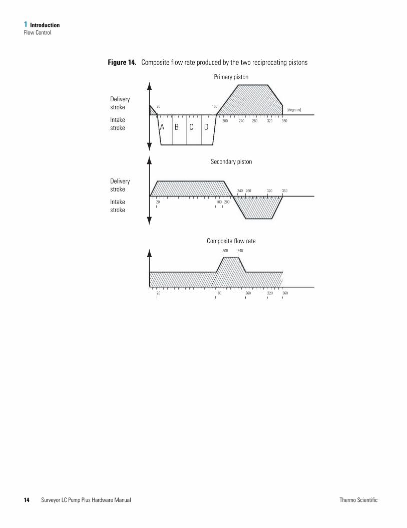
The pump cycle (see Figure 14), which is one full rotation of the camshaft, consists of three regions. The first region, which is the solvent proportioning region, begins at 20° rotation with the start of the intake stroke for the primary piston. As the primary piston begins to draw back, it creates a low-pressure zone that causes the inlet check valve to open. As the inlet check valve opens, eluent enters the primary pump head chamber.
Solvent proportioning occurs during the intake stroke of the primary piston. The valves of the solvent proportioning assembly open and close in the following order: B, C, D, and then A. During the intake stroke, the outlet check valve is closed, and all flow to the system comes from the secondary piston.
The second region, which is the compressibility region of the pump cycle, begins at 180° as the primary piston starts its forward stroke. The resulting high-pressure zone causes the inlet check valve to close while compressing the eluent in the primary pump chamber. As the pressure of the eluent in the primary pump head exceeds the column pressure, the outlet check valve opens, allowing eluent to enter the secondary pump chamber. For about 40° of the cam cycle, both pistons contribute flow to the system. The compressibility region of the pump cycle ends at 260° of the cam cycle, when the secondary piston reaches full intake.
During the compressibility region of the cam cycle, which begins with the forward stroke of the primary piston and ends with the intake stroke of the secondary piston, the on-board CPU monitors the backpressure of the eluent, as well as the position of the pistons, and adjusts the speed of the stepping motor to maintain constant flow.
The third region of the pump cycle extends from 260° to 20° rotation. In the third region of the pump cycle, the primary piston is providing all of the flow to the system as well as refilling the secondary piston chamber.
Surveyor LC Pump Plus Hardware Manual Thermo Scientific
1 IntroductionFlow Control
T
Figure 13. Flow control of the Surveyor LC Pump Plus by the step motor
Pulsedampener
Pressuresensor
Piston positionmonitor
Pressuremonitor
Control ofmotor rotation
Compressibility ofmobile phase valueupdated by operator
Flow rate setting inacquisition method
From solvent line
Inlet check valve
Primary pump head
Crossover tube
Outlet check valve
Outlet tube
Secondary pump head
Purgemanifold
To waste
To autosamplerDrain valve diversion
Steppingmotor
Photocoupler
Pistons
hermo Scientific Surveyor LC Pump Plus Hardware Manual 13
1 IntroductionFlow Control
14
Figure 14. Composite flow rate produced by the two reciprocating pistons
200 240
A B C D
160
200
240
280 320 360
[degrees]
260 320 360
180 200
180 260 320 360
240
20
20
20
Primary piston
Secondary piston
Composite flow rate
Deliverystroke
Intakestroke
Deliverystroke
Intakestroke
Surveyor LC Pump Plus Hardware Manual Thermo Scientific
1 IntroductionSpecifications
T
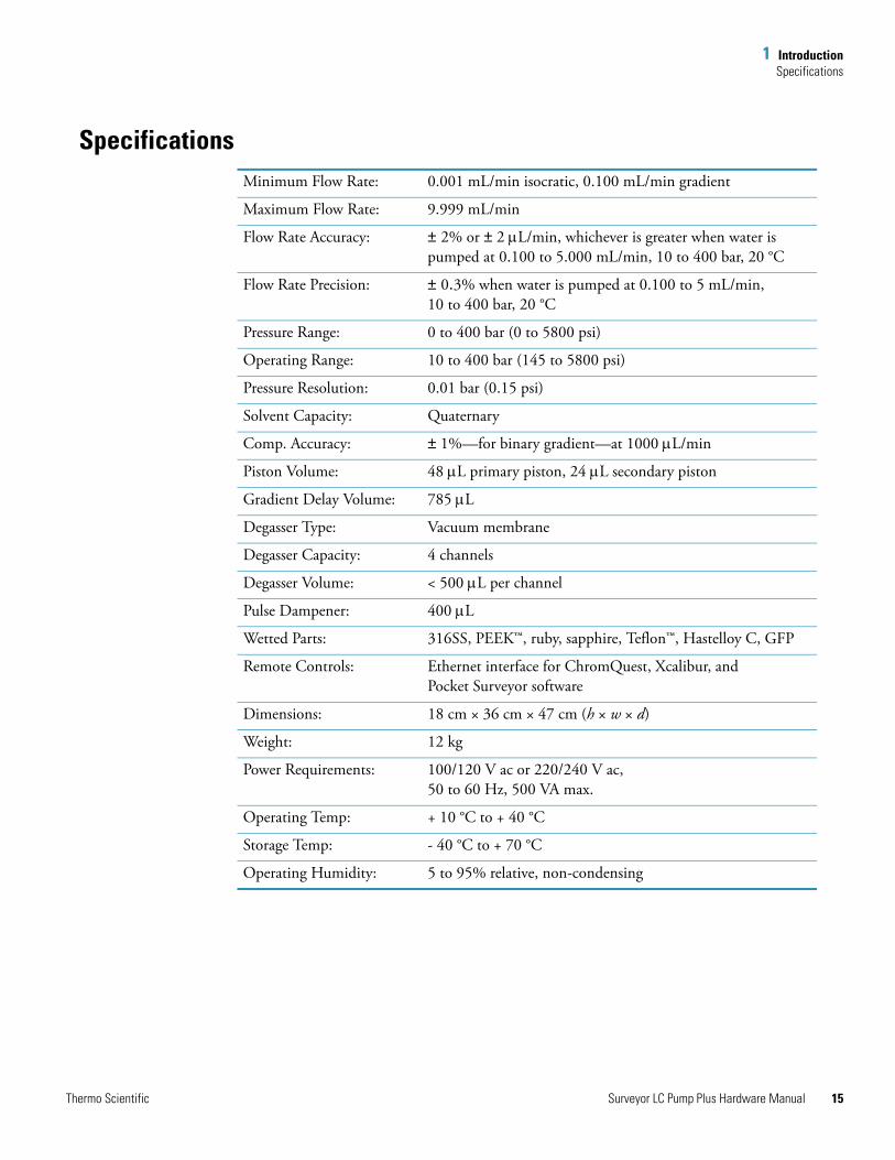
SpecificationsMinimum Flow Rate: 0.001 mL/min isocratic, 0.100 mL/min gradient
Maximum Flow Rate: 9.999 mL/min
Flow Rate Accuracy: ± 2% or ± 2 μL/min, whichever is greater when water is pumped at 0.100 to 5.000 mL/min, 10 to 400 bar, 20 °C
Flow Rate Precision: ± 0.3% when water is pumped at 0.100 to 5 mL/min, 10 to 400 bar, 20 °C
Pressure Range: 0 to 400 bar (0 to 5800 psi)
Operating Range: 10 to 400 bar (145 to 5800 psi)
Pressure Resolution: 0.01 bar (0.15 psi)
Solvent Capacity: Quaternary
Comp. Accuracy: ± 1%—for binary gradient—at 1000 μL/min
Piston Volume: 48 μL primary piston, 24 μL secondary piston
Gradient Delay Volume: 785 μL
Degasser Type: Vacuum membrane
Degasser Capacity: 4 channels
Degasser Volume: < 500 μL per channel
Pulse Dampener: 400 μL
Wetted Parts: 316SS, PEEK™, ruby, sapphire, Teflon™, Hastelloy C, GFP
Remote Controls: Ethernet interface for ChromQuest, Xcalibur, and Pocket Surveyor software
Dimensions: 18 cm × 36 cm × 47 cm (h × w × d)
Weight: 12 kg
Power Requirements: 100/120 V ac or 220/240 V ac, 50 to 60 Hz, 500 VA max.
Operating Temp: + 10 °C to + 40 °C
Storage Temp: - 40 °C to + 70 °C
Operating Humidity: 5 to 95% relative, non-condensing
hermo Scientific Surveyor LC Pump Plus Hardware Manual 15

2
Installation
This chapter describes the initial installation of your Surveyor LC Pump Plus, including connections to other chromatographic instrumentation. It contains an “Installation Checklist” on page 18. Use this checklist as a quick reference to conducting a successful installation. Make a copy of the checklist and fill it out when the installation is complete. Keep the completed checklist in your maintenance records.
Note Perform the installation in the sequence presented on the installation checklist and detailed in this chapter.
Contents
• Unpacking and Inspecting the Instrument
• Making Initial Instrument Preparations
• Connecting the Back Panel Cables
• Connecting the Solvent Lines
• Powering On the Pump for the First Time
• Calibrating the Surveyor LC Pump Plus
Thermo Scientific Surveyor LC Pump Plus Hardware Manual 17
2 InstallationInstallation Checklist
18
Installation ChecklistThe following Installation Checklist is a brief summary of the steps that you need to complete for the proper installation of your Surveyor LC Pump Plus.
Unpacking and Inspecting the InstrumentCarefully remove the pump from the shipping container and inspect both the pump and shipping materials for any signs of damage. If you find any damage, save the shipping materials and immediately contact the shipping company.
The shipping container should contain the following items:
• Surveyor LC Pump Plus
• Surveyor LC Pump Plus accessory kit
• A CD-ROM containing electronic copies of the manuals for the Surveyor Plus family of LC instruments
The items in the accessory kit are listed in Chapter 7, “Accessories and Replaceable Parts.”
Carefully check to make sure that you received all of the items listed on the packing list. If any items are missing, contact your Thermo Fisher Scientific representative immediately.
Unpack and inspect your instrument (page 18)
Read the safety notices (in the preface of this manual)
Make the initial instrument preparations (page 19)
Make the initial back panel connections (page 19)
Connect the solvent lines (page 21)
Power on the pump for the first time (page 26)
Install ChromQuest (version 4.2) or Xcalibur (version 2.0) software and connect remote communication outputs, as required.
This LC pump was installed by:
(Name) (Date)
Surveyor LC Pump Plus Hardware Manual Thermo Scientific
2 InstallationMaking Initial Instrument Preparations
Making Initial Instrument PreparationsPlace the pump on a bench top. Allow at least 15 cm (6 in.) of space between the back panel of the pump and any wall or obstruction. This provides access to the back-panel connectors and allows sufficient room for the ventilation of electronic components.
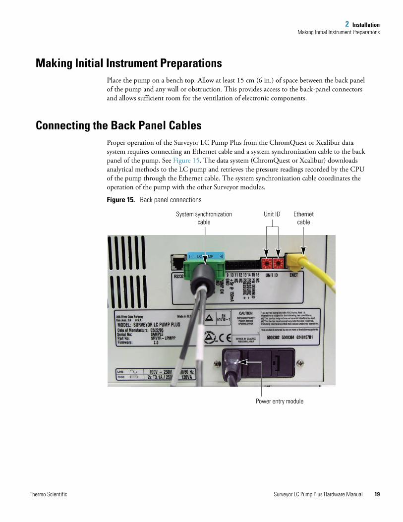
Connecting the Back Panel Cables Proper operation of the Surveyor LC Pump Plus from the ChromQuest or Xcalibur data system requires connecting an Ethernet cable and a system synchronization cable to the back panel of the pump. See Figure 15. The data system (ChromQuest or Xcalibur) downloads analytical methods to the LC pump and retrieves the pressure readings recorded by the CPU of the pump through the Ethernet cable. The system synchronization cable coordinates the operation of the pump with the other Surveyor modules.
Figure 15. Back panel connections
System synchronizationcable
Unit ID Ethernetcable
Power entry module
Thermo Scientific Surveyor LC Pump Plus Hardware Manual 19
2 InstallationConnecting the Back Panel Cables
20
System Synchronization Cable
The Surveyor system accessory kit (P/N SRVYR-SYSKT) contains two system synchronization cables. One cable has seven combicon connectors (P/N 60053-63034), and the other cable has five combicon connectors.
The five-combicon connector cable has labeled connectors for each of the three Surveyor modules. Locate the connector with the blue sticker labeled LC pump and attach the connector to the socket on the back panel of the pump as shown in Figure 15.
For information on the seven-combicon connector interconnect cable (P/N 60053-63034), see the Surveyor Plus Getting Connected Guide.
Ethernet Cable
Connect your Ethernet switch to the Ethernet connector outlet of the LC pump using the a shielded, CAT-5 Ethernet cable (P/N 70111-63302).
Unit ID Settings
The Surveyor LC Pump Plus is shipped with the unit ID preset. The unit ID consists of two rotary switches located on the back panel (Figure 15). The arrow in the center of the switch points to a digit from 0 to 9. The left rotary switch is the tens digit and the right rotary switch is the ones digit. The unit ID rotary switches can be set from 01 to 99. However, the unit ID setting must match the Stack Number that is specified in the Instrument Configuration application. The value of 0 is reserved for special service functions such as downloading new LC pump firmware.
Note For information on configuring the Surveyor LC Pump Plus, see the software manual for your data system. For ChromQuest, see the ChromQuest Chromatography Data System User’s Guide or the Surveyor Plus Getting Started with ChromQuest Guide. For Xcalibur, see the Surveyor Plus Getting Started with Xcalibur Guide.
Surveyor LC Pump Plus Hardware Manual Thermo Scientific
2 InstallationConnecting the Solvent Lines
Connecting the Solvent LinesYou need to connect solvent lines to and from the Surveyor LC Pump Plus before you can operate the pump. There are four low-pressure lines that deliver the four solvents to the solvent proportioning assembly of the pump and one high-pressure line that delivers the mobile phase to the autosampler.
Solvents should always be HPLC quality and free of particulate matter to avoid contaminating the check valves and the solvent proportioning valves. Aqueous eluents are particularly susceptible to bacterial growth, which can cause numerous problems.
To prevent bacteria and/or particulate matter from entering the pump
• Filter all solvents thoroughly.
• Discard aqueous mobile phases on a daily basis or add a bactericide such as sodium azide to inhibit bacterial growth (0.65 g/L NaN3 will prevent the growth of most kinds of bacteria).
Air permeates through FEP tubing and can saturate solvents inside the solvent lines when the system is left static (for example, over a weekend). In this case, purging the lines for a few minutes proves effective.
Solvent Inlet Lines
The Surveyor System Accessory Kit (P/N SRVYR-SYSKT) includes a 6 m (20 ft) length of FEP tubing (1/8-in. OD, 1/16-in. ID), which must be cut into four pieces for use as the solvent inlet lines. These lines are used to deliver each of the four solvents to the vacuum degassing assembly inside the Surveyor LC Pump Plus.
The accessory kit also includes four solvent reservoir bottle caps as well as a set of stick-on labels with the letters A, B, C, and D. Place these labels on your solvent reservoir bottle caps, and then use the solvent inlet lines to connect the solvent reservoir bottles to the corresponding degassing inlet.
Super Flangeless fittings are used to connect the solvent lines to the inlet ports of the built-in degasser. Connect the solvent reservoir bottle with the cap containing the label A to the A degas inlet, and so on.
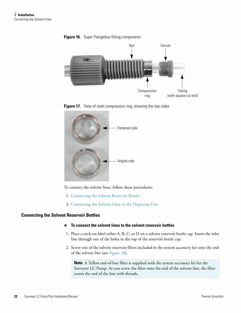
The Super Flangeless fitting consists of three components: a nut, a ferrule, and a stainless steel compression ring (see Figure 16). The compression ring has two sides: one side is flat, and one side is angled (see Figure 17). When you place the three components of the fitting on the end of a solvent line, the flat side of the ring faces the nut and the angled side of the ring faces the ferrule.
CAUTION Sodium azide is highly toxic and carcinogenic. Take care when disposing of solutions that contain sodium azide because azides can react with heavy metals to form explosive compounds.
Thermo Scientific Surveyor LC Pump Plus Hardware Manual 21
2 InstallationConnecting the Solvent Lines
22
Figure 16. Super Flangeless fitting components
Figure 17. View of steel compression ring, showing the two sides
To connect the solvent lines, follow these procedures:
1. Connecting the Solvent Reservoir Bottles
2. Connecting the Solvent Lines to the Degassing Unit
Connecting the Solvent Reservoir Bottles
To connect the solvent lines to the solvent reservoir bottles
1. Place a stick-on label either A, B, C, or D on a solvent reservoir bottle cap. Insert the inlet line through one of the holes in the top of the reservoir bottle cap.
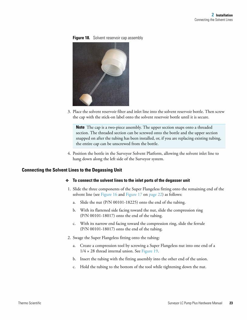
2. Screw one of the solvent reservoir filters included in the system accessory kit onto the end of the solvent line (see Figure 18).
Compressionring
Nut
Tubing(with square-cut end)
Ferrule
Flattened side
Angled side
Note A Teflon end-of-line filter is supplied with the system accessory kit for the Surveyor LC Pump. As you screw the filter onto the end of the solvent line, the filter scores the end of the line with threads.
Surveyor LC Pump Plus Hardware Manual Thermo Scientific
2 InstallationConnecting the Solvent Lines
Figure 18. Solvent reservoir cap assembly
3. Place the solvent reservoir filter and inlet line into the solvent reservoir bottle. Then screw the cap with the stick-on label onto the solvent reservoir bottle until it is secure.
4. Position the bottle in the Surveyor Solvent Platform, allowing the solvent inlet line to hang down along the left side of the Surveyor system.
Connecting the Solvent Lines to the Degassing Unit
To connect the solvent lines to the inlet ports of the degasser unit
1. Slide the three components of the Super Flangeless fitting onto the remaining end of the solvent line (see Figure 16 and Figure 17 on page 22) as follows:
a. Slide the nut (P/N 00101-18225) onto the end of the tubing.
b. With its flattened side facing toward the nut, slide the compression ring (P/N 00101-18017) onto the end of the tubing.
c. With its narrow end facing toward the compression ring, slide the ferrule (P/N 00101-18017) onto the end of the tubing.
2. Swage the Super Flangeless fitting onto the tubing:
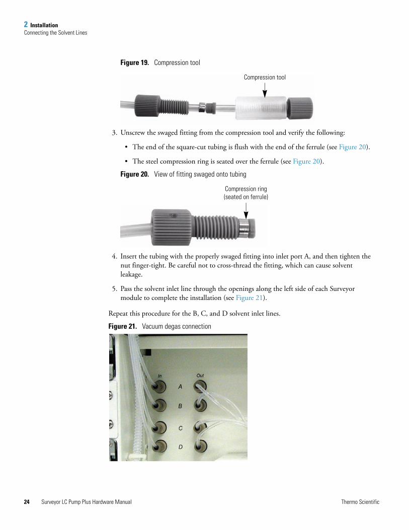
a. Create a compression tool by screwing a Super Flangeless nut into one end of a 1/4 × 28 thread internal union. See Figure 19.
b. Insert the tubing with the fitting assembly into the other end of the union.
c. Hold the tubing to the bottom of the tool while tightening down the nut.
Note The cap is a two-piece assembly. The upper section snaps onto a threaded section. The threaded section can be screwed onto the bottle and the upper section snapped on after the tubing has been installed, or, if you are replacing existing tubing, the entire cap can be unscrewed from the bottle.
Thermo Scientific Surveyor LC Pump Plus Hardware Manual 23
2 InstallationConnecting the Solvent Lines
24
Figure 19. Compression tool
3. Unscrew the swaged fitting from the compression tool and verify the following:
• The end of the square-cut tubing is flush with the end of the ferrule (see Figure 20).
• The steel compression ring is seated over the ferrule (see Figure 20).
Figure 20. View of fitting swaged onto tubing
4. Insert the tubing with the properly swaged fitting into inlet port A, and then tighten the nut finger-tight. Be careful not to cross-thread the fitting, which can cause solvent leakage.
5. Pass the solvent inlet line through the openings along the left side of each Surveyor module to complete the installation (see Figure 21).
Repeat this procedure for the B, C, and D solvent inlet lines.
Figure 21. Vacuum degas connection
Compression tool
Compression ring(seated on ferrule)
Surveyor LC Pump Plus Hardware Manual Thermo Scientific
2 InstallationConnecting the Solvent Lines
Solvent Outlet Tubing
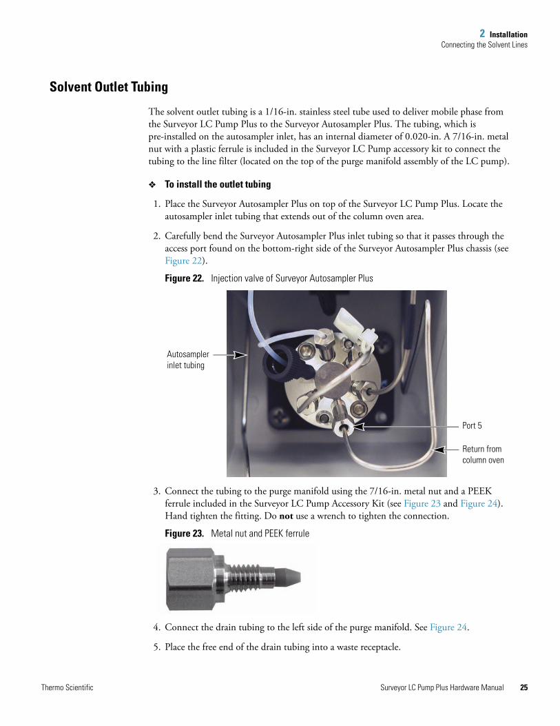
The solvent outlet tubing is a 1/16-in. stainless steel tube used to deliver mobile phase from the Surveyor LC Pump Plus to the Surveyor Autosampler Plus. The tubing, which is pre-installed on the autosampler inlet, has an internal diameter of 0.020-in. A 7/16-in. metal nut with a plastic ferrule is included in the Surveyor LC Pump accessory kit to connect the tubing to the line filter (located on the top of the purge manifold assembly of the LC pump).
To install the outlet tubing
1. Place the Surveyor Autosampler Plus on top of the Surveyor LC Pump Plus. Locate the autosampler inlet tubing that extends out of the column oven area.
2. Carefully bend the Surveyor Autosampler Plus inlet tubing so that it passes through the access port found on the bottom-right side of the Surveyor Autosampler Plus chassis (see Figure 22).
Figure 22. Injection valve of Surveyor Autosampler Plus
3. Connect the tubing to the purge manifold using the 7/16-in. metal nut and a PEEK ferrule included in the Surveyor LC Pump Accessory Kit (see Figure 23 and Figure 24). Hand tighten the fitting. Do not use a wrench to tighten the connection.
Figure 23. Metal nut and PEEK ferrule
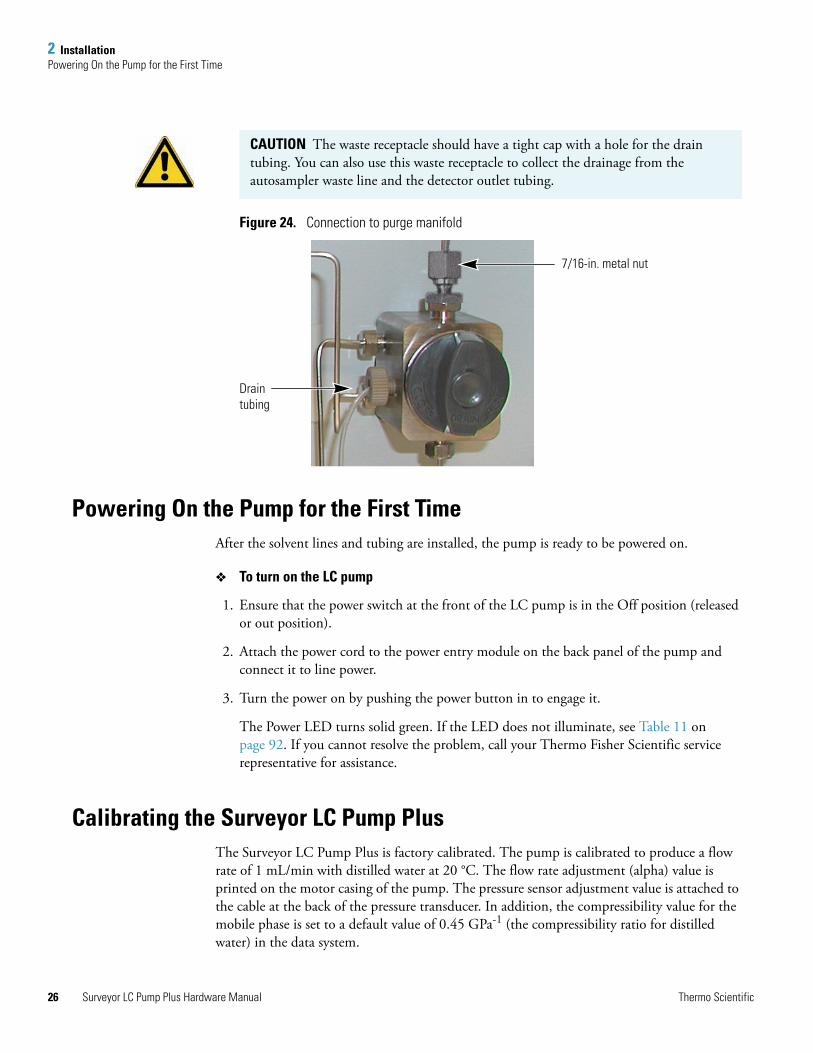
4. Connect the drain tubing to the left side of the purge manifold. See Figure 24.
5. Place the free end of the drain tubing into a waste receptacle.
Autosampler inlet tubing
Port 5
Return from column oven
Thermo Scientific Surveyor LC Pump Plus Hardware Manual 25
2 InstallationPowering On the Pump for the First Time
26
Figure 24. Connection to purge manifold
Powering On the Pump for the First TimeAfter the solvent lines and tubing are installed, the pump is ready to be powered on.
To turn on the LC pump
1. Ensure that the power switch at the front of the LC pump is in the Off position (released or out position).
2. Attach the power cord to the power entry module on the back panel of the pump and connect it to line power.
3. Turn the power on by pushing the power button in to engage it.
The Power LED turns solid green. If the LED does not illuminate, see Table 11 on page 92. If you cannot resolve the problem, call your Thermo Fisher Scientific service representative for assistance.
Calibrating the Surveyor LC Pump Plus The Surveyor LC Pump Plus is factory calibrated. The pump is calibrated to produce a flow rate of 1 mL/min with distilled water at 20 °C. The flow rate adjustment (alpha) value is printed on the motor casing of the pump. The pressure sensor adjustment value is attached to the cable at the back of the pressure transducer. In addition, the compressibility value for the mobile phase is set to a default value of 0.45 GPa-1 (the compressibility ratio for distilled water) in the data system.
CAUTION The waste receptacle should have a tight cap with a hole for the drain tubing. You can also use this waste receptacle to collect the drainage from the autosampler waste line and the detector outlet tubing.
Drain tubing
7/16-in. metal nut
Surveyor LC Pump Plus Hardware Manual Thermo Scientific
3
Data System Instrument Configuration
This chapter describes how to add the Surveyor LC Pump Plus to the data system instrument configuration and how to configure the Surveyor Autosampler Plus to recognize the active high input signals issued from the Surveyor LC Pump Plus.
To add the Surveyor LC Pump Plus to the software configuration, follow the instructions for your data system.
Adding the Surveyor LC Pump Plus to the ChromQuest ConfigurationTo control the Surveyor LC Pump Plus from the ChromQuest data system you must add it to the instrument configuration. You must also configure the Surveyor Autosampler Plus signal polarities to recognize the output signals from the Surveyor LC Pump Plus.
To add the Surveyor LC Pump Plus to the instrument configuration and specify the appropriate contact closure signals for the Surveyor Autosampler Plus, follow these procedures:
• Configuring the Surveyor LC Pump Plus Device Driver
• Configuring the Signal Polarities for the Surveyor AS in ChromQuest
Note If the signal polarities for the Surveyor Autosampler Plus are not configured correctly, the run status remains at “Waiting for Trigger.”
Contents
• Adding the Surveyor LC Pump Plus to the ChromQuest Configuration
• Adding the Surveyor LC Pump to the Xcalibur Instrument Configuration
Thermo Scientific Surveyor LC Pump Plus Hardware Manual 27
3 Data System Instrument ConfigurationAdding the Surveyor LC Pump Plus to the ChromQuest Configuration
28
Configuring the Surveyor LC Pump Plus Device Driver
The following procedure assumes that you are adding the Surveyor LC Pump Plus to a Surveyor instrument that already exists in the ChromQuest Enterprise. If you have not yet added an instrument to your Enterprise, refer to the Surveyor Plus Getting Started with ChromQuest Guide.
To add the Surveyor LC Pump Plus to the instrument configuration
1. Do one of the following:
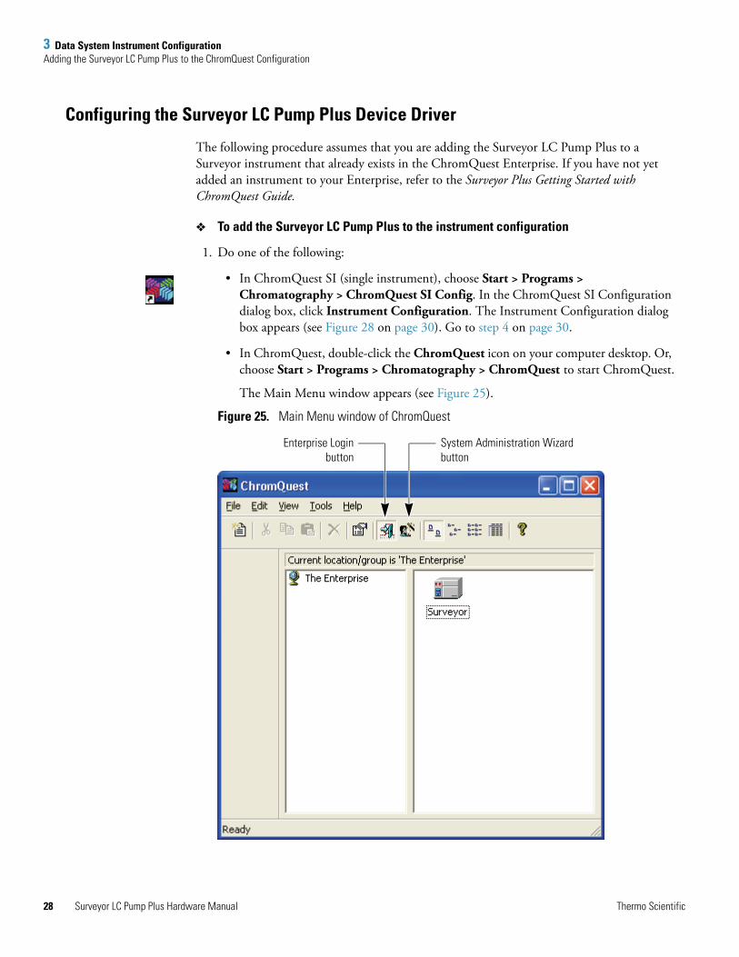
• In ChromQuest SI (single instrument), choose Start > Programs > Chromatography > ChromQuest SI Config. In the ChromQuest SI Configuration dialog box, click Instrument Configuration. The Instrument Configuration dialog box appears (see Figure 28 on page 30). Go to step 4 on page 30.
• In ChromQuest, double-click the ChromQuest icon on your computer desktop. Or, choose Start > Programs > Chromatography > ChromQuest to start ChromQuest.
The Main Menu window appears (see Figure 25).
Figure 25. Main Menu window of ChromQuest
System Administration Wizardbutton
Enterprise Loginbutton
Surveyor LC Pump Plus Hardware Manual Thermo Scientific
3 Data System Instrument ConfigurationAdding the Surveyor LC Pump Plus to the ChromQuest Configuration
T
2. In ChromQuest, log in, if necessary.
If the System Administration Wizard button is locked, the security feature is enabled and you are required to login.
To log in to the ChromQuest data system:
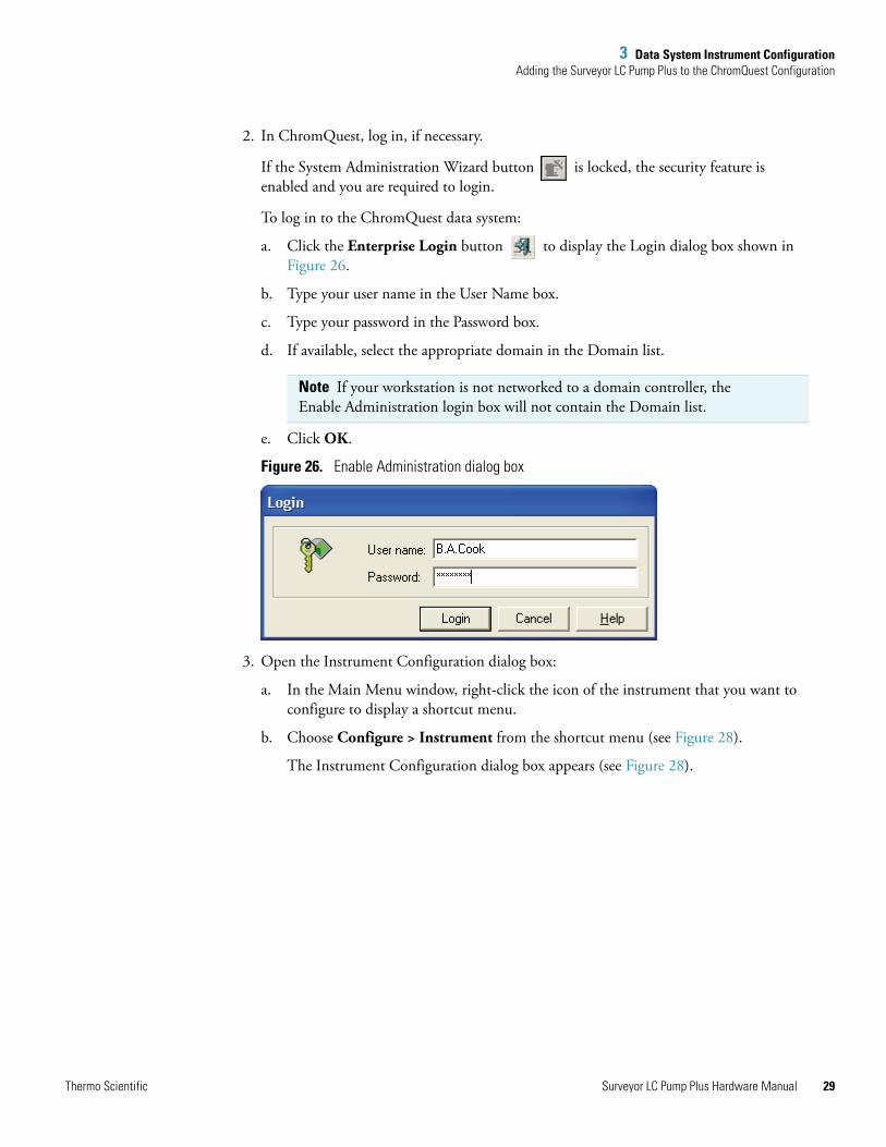
a. Click the Enterprise Login button to display the Login dialog box shown in Figure 26.
b. Type your user name in the User Name box.
c. Type your password in the Password box.
d. If available, select the appropriate domain in the Domain list.
e. Click OK.
Figure 26. Enable Administration dialog box
3. Open the Instrument Configuration dialog box:
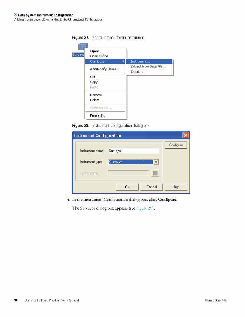
a. In the Main Menu window, right-click the icon of the instrument that you want to configure to display a shortcut menu.
b. Choose Configure > Instrument from the shortcut menu (see Figure 28).
The Instrument Configuration dialog box appears (see Figure 28).
Note If your workstation is not networked to a domain controller, the Enable Administration login box will not contain the Domain list.
hermo Scientific Surveyor LC Pump Plus Hardware Manual 29
3 Data System Instrument ConfigurationAdding the Surveyor LC Pump Plus to the ChromQuest Configuration
30
Figure 27. Shortcut menu for an instrument
Figure 28. Instrument Configuration dialog box
4. In the Instrument Configuration dialog box, click Configure.
The Surveyor dialog box appears (see Figure 29).
Surveyor LC Pump Plus Hardware Manual Thermo Scientific
3 Data System Instrument ConfigurationAdding the Surveyor LC Pump Plus to the ChromQuest Configuration
T
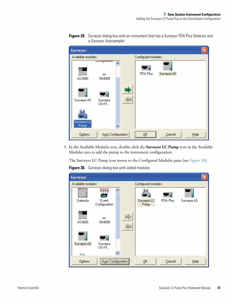
Figure 29. Surveyor dialog box with an instrument that has a Surveyor PDA Plus Detector and a Surveyor Autosampler
5. In the Available Modules area, double-click the Surveyor LC Pump icon in the Available Modules area to add the pump to the instrument configuration.
The Surveyor LC Pump icon moves to the Configured Modules pane (see Figure 30).
Figure 30. Surveyor dialog box with added modules
hermo Scientific Surveyor LC Pump Plus Hardware Manual 31
3 Data System Instrument ConfigurationAdding the Surveyor LC Pump Plus to the ChromQuest Configuration
32
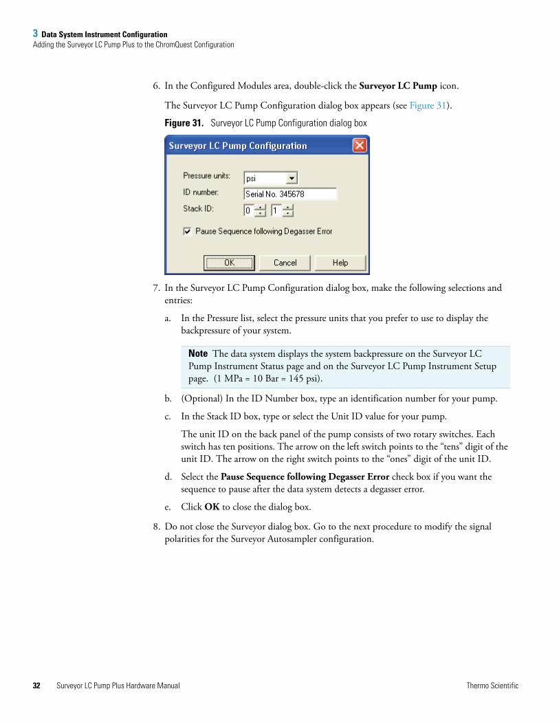
6. In the Configured Modules area, double-click the Surveyor LC Pump icon.
The Surveyor LC Pump Configuration dialog box appears (see Figure 31).
Figure 31. Surveyor LC Pump Configuration dialog box
7. In the Surveyor LC Pump Configuration dialog box, make the following selections and entries:
a. In the Pressure list, select the pressure units that you prefer to use to display the backpressure of your system.
b. (Optional) In the ID Number box, type an identification number for your pump.
c. In the Stack ID box, type or select the Unit ID value for your pump.
The unit ID on the back panel of the pump consists of two rotary switches. Each switch has ten positions. The arrow on the left switch points to the “tens” digit of the unit ID. The arrow on the right switch points to the “ones” digit of the unit ID.
d. Select the Pause Sequence following Degasser Error check box if you want the sequence to pause after the data system detects a degasser error.
e. Click OK to close the dialog box.
8. Do not close the Surveyor dialog box. Go to the next procedure to modify the signal polarities for the Surveyor Autosampler configuration.
Note The data system displays the system backpressure on the Surveyor LC Pump Instrument Status page and on the Surveyor LC Pump Instrument Setup page. (1 MPa = 10 Bar = 145 psi).
Surveyor LC Pump Plus Hardware Manual Thermo Scientific
3 Data System Instrument ConfigurationAdding the Surveyor LC Pump Plus to the ChromQuest Configuration
T
Configuring the Signal Polarities for the Surveyor AS in ChromQuest
To configure the signal polarities for the Surveyor Autosampler in ChromQuest
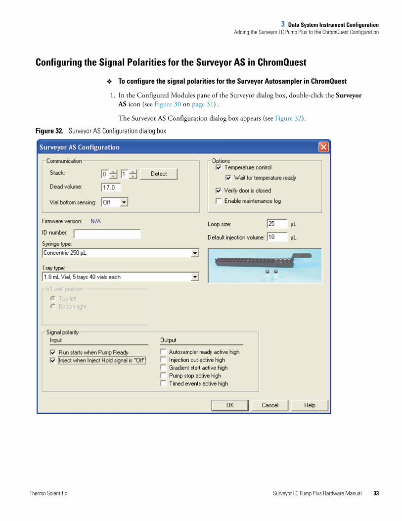
1. In the Configured Modules pane of the Surveyor dialog box, double-click the Surveyor AS icon (see Figure 30 on page 31) .
The Surveyor AS Configuration dialog box appears (see Figure 32).
Figure 32. Surveyor AS Configuration dialog box
hermo Scientific Surveyor LC Pump Plus Hardware Manual 33
3 Data System Instrument ConfigurationAdding the Surveyor LC Pump to the Xcalibur Instrument Configuration
34
2. Ensure that the Run starts when Pump Ready check box and the Inject when Inject Hold signal is “Off ” check boxes are selected.
3. Exit the Configuration application and return to the Main Menu window:
a. Click OK to close the Surveyor AS Configuration dialog box.
b. Click OK to close the Surveyor dialog box.
c. Click OK to close the Instrument Configuration dialog box and return to the Main Menu window in ChromQuest.
Adding the Surveyor LC Pump to the Xcalibur Instrument Configuration
To control the Surveyor LC Pump Plus from the Xcalibur data system you must add it to the Xcalibur instrument configuration. You must also configure the Surveyor Autosampler Plus signal polarities to recognize the output signals from the Surveyor LC Pump Plus.
To add the Surveyor LC Pump Plus to the software configuration, follow these procedures:
• Configuring the Surveyor LC Pump
• Configuring the Signal Polarities for the Surveyor AS
Configuring the Surveyor LC Pump
To add the Surveyor LC Pump Plus to the Xcalibur instrument configuration
1. Depending on the Xcalibur version, do one of the following:
• For Xcalibur 2.0 or below, choose Start > All Programs > Xcalibur > Instrument Configuration.
The Instrument Configuration window appears.
• For Xcalibur 2.1, choose Start > All Programs > Thermo Foundation 1.0 > Instrument Configuration.
The Thermo Foundation Instrument Configuration window appears.
2. In the Device Types list, select All to show all the instruments. The configurable instruments appear as buttons in the Available Devices area.
3. In the Available Devices area, double-click the Surveyor LC Pump button. A copy of the Surveyor LC Pump button appears in the Configured Devices area.
4. In the Configured Devices area, double-click the Surveyor LC Pump button.
Note Refer to the Surveyor Plus Getting Started with ChromQuest Guide for detailed instructions on configuring your Surveyor Autosampler Plus.
Surveyor LC Pump Plus Hardware Manual Thermo Scientific
3 Data System Instrument ConfigurationAdding the Surveyor LC Pump to the Xcalibur Instrument Configuration
T
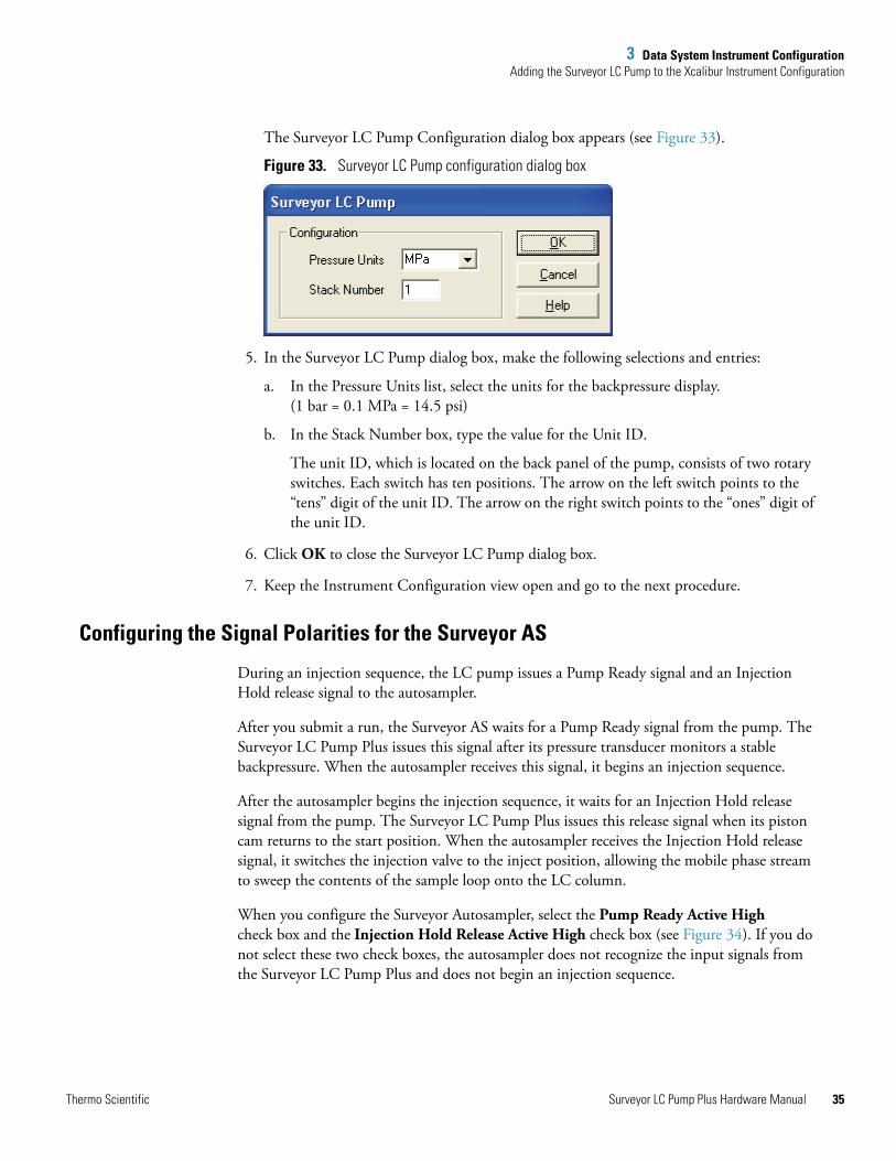
The Surveyor LC Pump Configuration dialog box appears (see Figure 33).
Figure 33. Surveyor LC Pump configuration dialog box
5. In the Surveyor LC Pump dialog box, make the following selections and entries:
a. In the Pressure Units list, select the units for the backpressure display. (1 bar = 0.1 MPa = 14.5 psi)
b. In the Stack Number box, type the value for the Unit ID.
The unit ID, which is located on the back panel of the pump, consists of two rotary switches. Each switch has ten positions. The arrow on the left switch points to the “tens” digit of the unit ID. The arrow on the right switch points to the “ones” digit of the unit ID.
6. Click OK to close the Surveyor LC Pump dialog box.
7. Keep the Instrument Configuration view open and go to the next procedure.
Configuring the Signal Polarities for the Surveyor AS
During an injection sequence, the LC pump issues a Pump Ready signal and an Injection Hold release signal to the autosampler.
After you submit a run, the Surveyor AS waits for a Pump Ready signal from the pump. The Surveyor LC Pump Plus issues this signal after its pressure transducer monitors a stable backpressure. When the autosampler receives this signal, it begins an injection sequence.
After the autosampler begins the injection sequence, it waits for an Injection Hold release signal from the pump. The Surveyor LC Pump Plus issues this release signal when its piston cam returns to the start position. When the autosampler receives the Injection Hold release signal, it switches the injection valve to the inject position, allowing the mobile phase stream to sweep the contents of the sample loop onto the LC column.
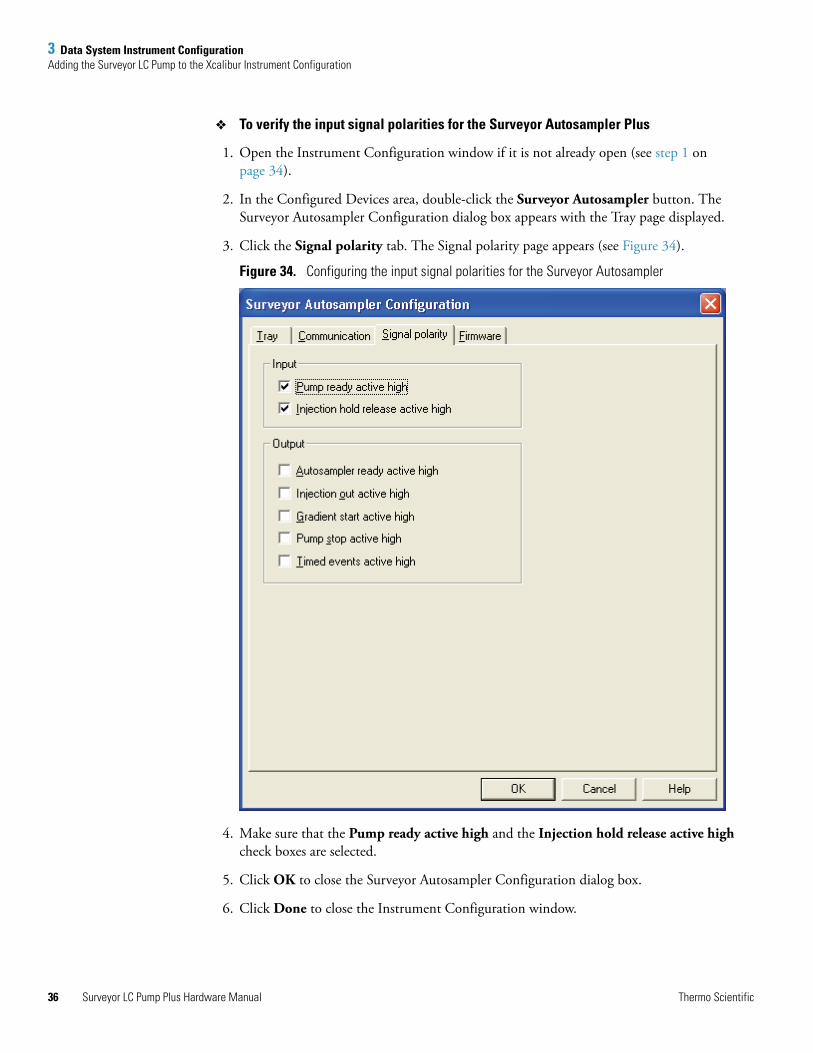
When you configure the Surveyor Autosampler, select the Pump Ready Active High check box and the Injection Hold Release Active High check box (see Figure 34). If you do not select these two check boxes, the autosampler does not recognize the input signals from the Surveyor LC Pump Plus and does not begin an injection sequence.
hermo Scientific Surveyor LC Pump Plus Hardware Manual 35
3 Data System Instrument ConfigurationAdding the Surveyor LC Pump to the Xcalibur Instrument Configuration
36
To verify the input signal polarities for the Surveyor Autosampler Plus
1. Open the Instrument Configuration window if it is not already open (see step 1 on page 34).
2. In the Configured Devices area, double-click the Surveyor Autosampler button. The Surveyor Autosampler Configuration dialog box appears with the Tray page displayed.
3. Click the Signal polarity tab. The Signal polarity page appears (see Figure 34).
Figure 34. Configuring the input signal polarities for the Surveyor Autosampler
4. Make sure that the Pump ready active high and the Injection hold release active high check boxes are selected.
5. Click OK to close the Surveyor Autosampler Configuration dialog box.
6. Click Done to close the Instrument Configuration window.
Surveyor LC Pump Plus Hardware Manual Thermo Scientific
4
Maintenance
The five main components of the Surveyor LC Pump Plus are the degassing unit, the solvent proportioning unit, the pulse dampener, the pump head assemblies, and the purge manifold assembly. As a chromatographer, you are responsible for the routine maintenance of the pump head assemblies. You are also responsible for replacing the frit, which is inside the line filter body connected to the top of the purge manifold assembly.
Contact your local Thermo Fisher Scientific service representative if you suspect a mechanical problem with the degassing unit, the solvent proportioning unit, or the pulse dampener.
This chapter covers the routine maintenance of the two pump head assemblies, as well as standard operating procedures to prolong the lifespan of the piston seals and the pistons.
Contents
• Maintenance Schedule
• Maintenance Page in ChromQuest
• Maintenance Page in Xcalibur
• Rinsing the Pistons
• Cleaning the Check Valves
• Maintaining the Pump Head Assemblies
• Replacing the Line Filter Frit
• Replacing the Solvent Reservoir Filter
• Purging Air from the Solvent Lines or the Pump Heads
• Replacing the Drain Valve Knob O-Ring
• Replacing the Fuses
Thermo Scientific Surveyor LC Pump Plus Hardware Manual 37
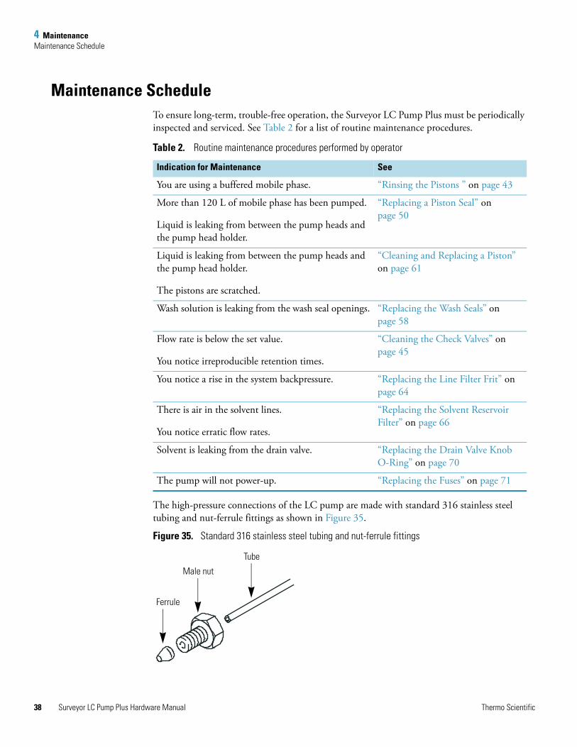
4 MaintenanceMaintenance Schedule
38
Maintenance ScheduleTo ensure long-term, trouble-free operation, the Surveyor LC Pump Plus must be periodically inspected and serviced. See Table 2 for a list of routine maintenance procedures.
The high-pressure connections of the LC pump are made with standard 316 stainless steel tubing and nut-ferrule fittings as shown in Figure 35.
Figure 35. Standard 316 stainless steel tubing and nut-ferrule fittings
Table 2. Routine maintenance procedures performed by operator
Indication for Maintenance See
You are using a buffered mobile phase. “Rinsing the Pistons ” on page 43
More than 120 L of mobile phase has been pumped.
Liquid is leaking from between the pump heads and the pump head holder.
“Replacing a Piston Seal” on page 50
Liquid is leaking from between the pump heads and the pump head holder.
The pistons are scratched.
“Cleaning and Replacing a Piston” on page 61
Wash solution is leaking from the wash seal openings. “Replacing the Wash Seals” on page 58
Flow rate is below the set value.
You notice irreproducible retention times.
“Cleaning the Check Valves” on page 45
You notice a rise in the system backpressure. “Replacing the Line Filter Frit” on page 64
There is air in the solvent lines.
You notice erratic flow rates.
“Replacing the Solvent Reservoir Filter” on page 66
Solvent is leaking from the drain valve. “Replacing the Drain Valve Knob O-Ring” on page 70
The pump will not power-up. “Replacing the Fuses” on page 71
Ferrule
Male nut
Tube
Surveyor LC Pump Plus Hardware Manual Thermo Scientific
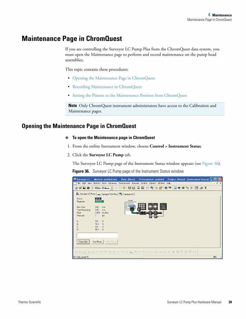
4 MaintenanceMaintenance Page in ChromQuest
Maintenance Page in ChromQuestIf you are controlling the Surveyor LC Pump Plus from the ChromQuest data system, you must open the Maintenance page to perform and record maintenance on the pump head assemblies.
This topic contains these procedures:
• Opening the Maintenance Page in ChromQuest
• Recording Maintenance in ChromQuest
• Setting the Pistons to the Maintenance Position from ChromQuest
Opening the Maintenance Page in ChromQuest
To open the Maintenance page in ChromQuest
1. From the online Instrument window, choose Control > Instrument Status.
2. Click the Surveyor LC Pump tab.
The Surveyor LC Pump page of the Instrument Status window appears (see Figure 36).
Figure 36. Surveyor LC Pump page of the Instrument Status window
Note Only ChromQuest instrument administrators have access to the Calibration and Maintenance pages.
Thermo Scientific Surveyor LC Pump Plus Hardware Manual 39

4 MaintenanceMaintenance Page in ChromQuest
40
3. Click Diagnostics. The Diagnostics dialog box appears.
4. Click the Maintenance tab. The Maintenance page appears (see Figure 37).
Figure 37. Maintenance page of the Diagnostics dialog box
Recording Maintenance in ChromQuest
ChromQuest has a built-in feature for tracking the volume of mobile phase pumped by the Surveyor LC Pump Plus. This information, which pertains to seal wear, appears in the Maintenance page.
Each pump head assembly contains a piston seal. The two seals can wear at different rates, causing leaks to occur in one or both pump heads. Before dismantling the pump head assemblies, attempt to determine the source of the leakage. To save time and materials, replace only the piston seal in the pump head assembly that is leaking. Alternatively, as a preventive measure, replace the piston seals after pumping 120 L of mobile phase.
Surveyor LC Pump Plus Hardware Manual Thermo Scientific
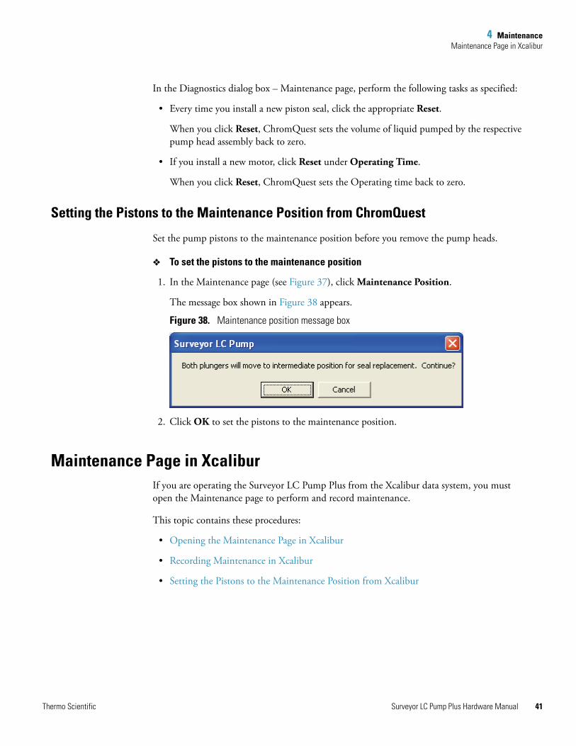
4 MaintenanceMaintenance Page in Xcalibur
In the Diagnostics dialog box – Maintenance page, perform the following tasks as specified:
• Every time you install a new piston seal, click the appropriate Reset.
When you click Reset, ChromQuest sets the volume of liquid pumped by the respective pump head assembly back to zero.
• If you install a new motor, click Reset under Operating Time.
When you click Reset, ChromQuest sets the Operating time back to zero.
Setting the Pistons to the Maintenance Position from ChromQuest
Set the pump pistons to the maintenance position before you remove the pump heads.
To set the pistons to the maintenance position
1. In the Maintenance page (see Figure 37), click Maintenance Position.
The message box shown in Figure 38 appears.
Figure 38. Maintenance position message box
2. Click OK to set the pistons to the maintenance position.
Maintenance Page in XcaliburIf you are operating the Surveyor LC Pump Plus from the Xcalibur data system, you must open the Maintenance page to perform and record maintenance.
This topic contains these procedures:
• Opening the Maintenance Page in Xcalibur
• Recording Maintenance in Xcalibur
• Setting the Pistons to the Maintenance Position from Xcalibur
Thermo Scientific Surveyor LC Pump Plus Hardware Manual 41
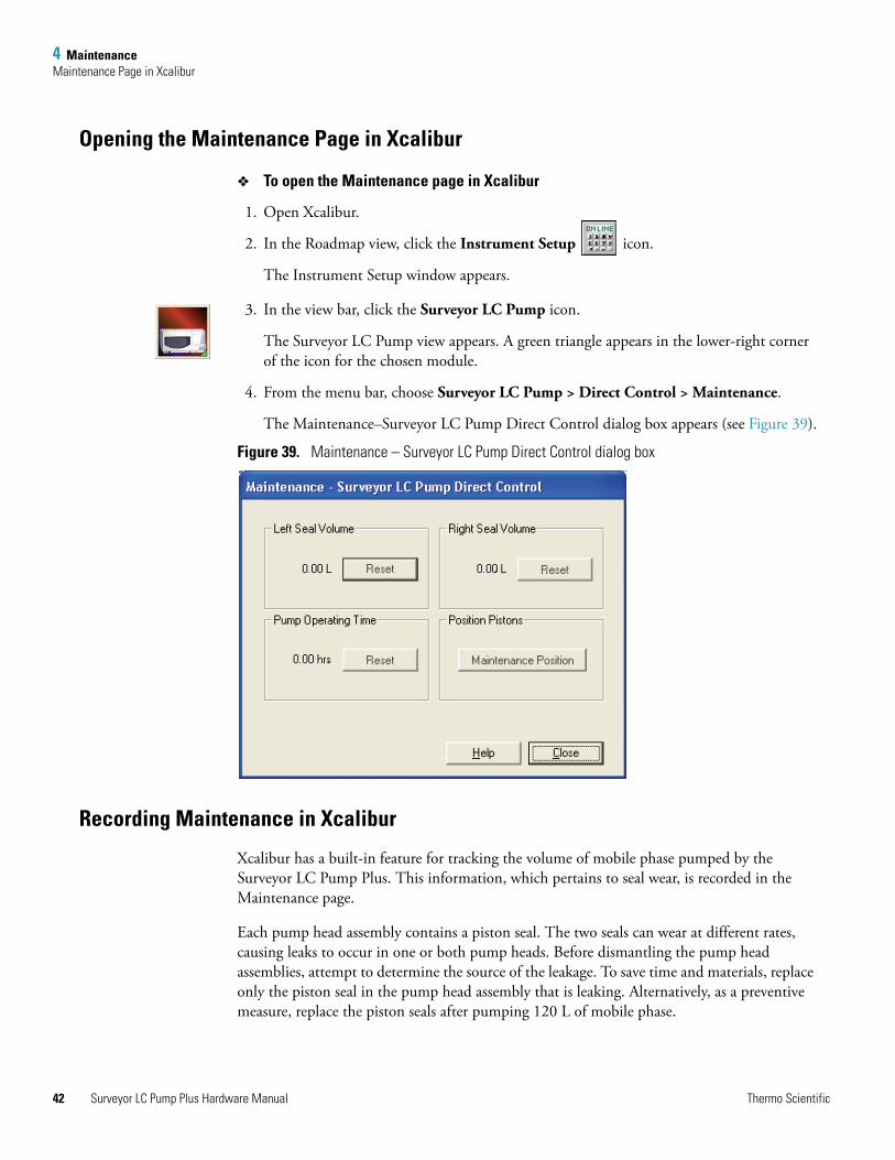
4 MaintenanceMaintenance Page in Xcalibur
42
Opening the Maintenance Page in Xcalibur
To open the Maintenance page in Xcalibur
1. Open Xcalibur.
2. In the Roadmap view, click the Instrument Setup icon.
The Instrument Setup window appears.
3. In the view bar, click the Surveyor LC Pump icon.
The Surveyor LC Pump view appears. A green triangle appears in the lower-right corner of the icon for the chosen module.
4. From the menu bar, choose Surveyor LC Pump > Direct Control > Maintenance.
The Maintenance–Surveyor LC Pump Direct Control dialog box appears (see Figure 39).
Figure 39. Maintenance – Surveyor LC Pump Direct Control dialog box
Recording Maintenance in Xcalibur
Xcalibur has a built-in feature for tracking the volume of mobile phase pumped by the Surveyor LC Pump Plus. This information, which pertains to seal wear, is recorded in the Maintenance page.
Each pump head assembly contains a piston seal. The two seals can wear at different rates, causing leaks to occur in one or both pump heads. Before dismantling the pump head assemblies, attempt to determine the source of the leakage. To save time and materials, replace only the piston seal in the pump head assembly that is leaking. Alternatively, as a preventive measure, replace the piston seals after pumping 120 L of mobile phase.
Surveyor LC Pump Plus Hardware Manual Thermo Scientific
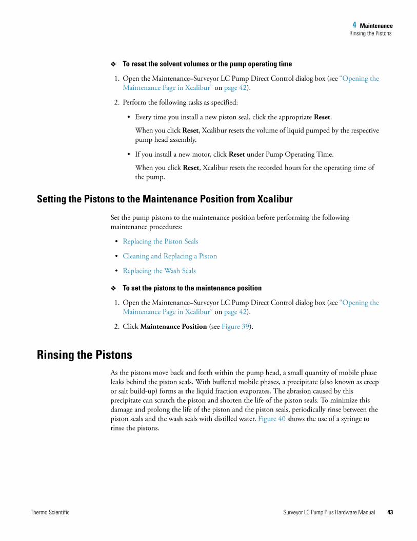
4 MaintenanceRinsing the Pistons
To reset the solvent volumes or the pump operating time
1. Open the Maintenance–Surveyor LC Pump Direct Control dialog box (see “Opening the Maintenance Page in Xcalibur” on page 42).
2. Perform the following tasks as specified:
• Every time you install a new piston seal, click the appropriate Reset.
When you click Reset, Xcalibur resets the volume of liquid pumped by the respective pump head assembly.
• If you install a new motor, click Reset under Pump Operating Time.
When you click Reset, Xcalibur resets the recorded hours for the operating time of the pump.
Setting the Pistons to the Maintenance Position from Xcalibur
Set the pump pistons to the maintenance position before performing the following maintenance procedures:
• Replacing the Piston Seals
• Cleaning and Replacing a Piston
• Replacing the Wash Seals
To set the pistons to the maintenance position
1. Open the Maintenance–Surveyor LC Pump Direct Control dialog box (see “Opening the Maintenance Page in Xcalibur” on page 42).
2. Click Maintenance Position (see Figure 39).
Rinsing the Pistons As the pistons move back and forth within the pump head, a small quantity of mobile phase leaks behind the piston seals. With buffered mobile phases, a precipitate (also known as creep or salt build-up) forms as the liquid fraction evaporates. The abrasion caused by this precipitate can scratch the piston and shorten the life of the piston seals. To minimize this damage and prolong the life of the piston and the piston seals, periodically rinse between the piston seals and the wash seals with distilled water. Figure 40 shows the use of a syringe to rinse the pistons.
Thermo Scientific Surveyor LC Pump Plus Hardware Manual 43
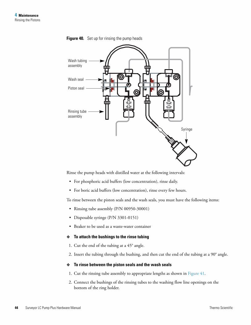
4 MaintenanceRinsing the Pistons
44
Figure 40. Set up for rinsing the pump heads
Rinse the pump heads with distilled water at the following intervals:
• For phosphoric acid buffers (low concentration), rinse daily.
• For boric acid buffers (low concentration), rinse every few hours.
To rinse between the piston seals and the wash seals, you must have the following items:
• Rinsing tube assembly (P/N 00950-30001)
• Disposable syringe (P/N 3301-0151)
• Beaker to be used as a waste-water container
To attach the bushings to the rinse tubing
1. Cut the end of the tubing at a 45° angle.
2. Insert the tubing through the bushing, and then cut the end of the tubing at a 90° angle.
To rinse between the piston seals and the wash seals
1. Cut the rinsing tube assembly to appropriate lengths as shown in Figure 41.
2. Connect the bushings of the rinsing tubes to the washing flow line openings on the bottom of the ring holder.
Wash tubing assembly
Wash seal
Piston seal
Rinsing tube assembly
Syringe
Surveyor LC Pump Plus Hardware Manual Thermo Scientific
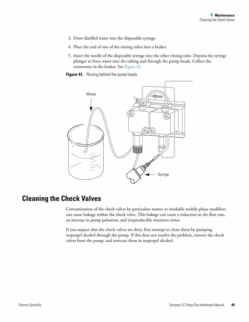
4 MaintenanceCleaning the Check Valves
3. Draw distilled water into the disposable syringe.
4. Place the end of one of the rinsing tubes into a beaker.
5. Insert the needle of the disposable syringe into the other rinsing tube. Depress the syringe plunger to force water into the tubing and through the pump heads. Collect the wastewater in the beaker. See Figure 41.
Figure 41. Rinsing behind the pump heads
Cleaning the Check ValvesContamination of the check valves by particulate matter or insoluble mobile phase modifiers can cause leakage within the check valve. This leakage can cause a reduction in the flow rate, an increase in pump pulsation, and irreproducible retention times.
If you suspect that the check valves are dirty, first attempt to clean them by pumping isopropyl alcohol through the pump. If this does not resolve the problem, remove the check valves from the pump, and sonicate them in isopropyl alcohol.
Waste
Syringe
Thermo Scientific Surveyor LC Pump Plus Hardware Manual 45
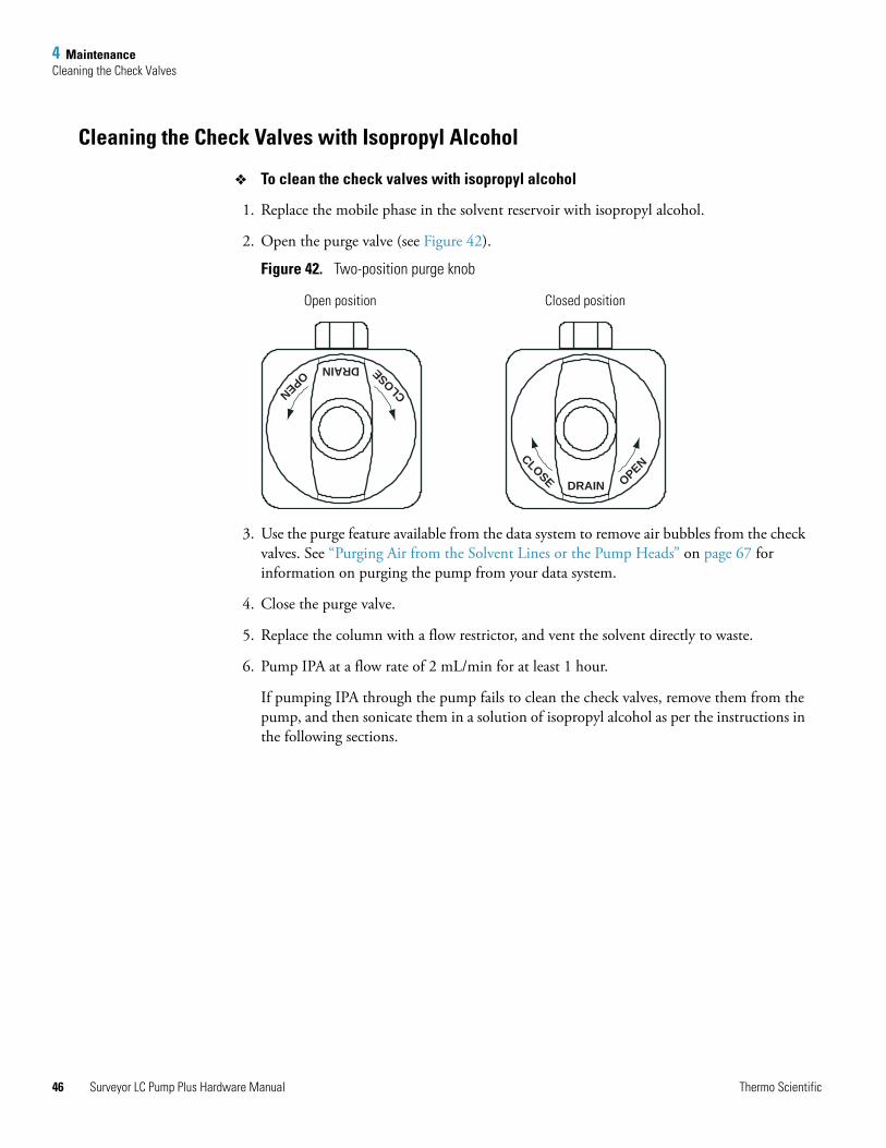
4 MaintenanceCleaning the Check Valves
46
Cleaning the Check Valves with Isopropyl Alcohol
To clean the check valves with isopropyl alcohol
1. Replace the mobile phase in the solvent reservoir with isopropyl alcohol.
2. Open the purge valve (see Figure 42).
Figure 42. Two-position purge knob
3. Use the purge feature available from the data system to remove air bubbles from the check valves. See “Purging Air from the Solvent Lines or the Pump Heads” on page 67 for information on purging the pump from your data system.
4. Close the purge valve.
5. Replace the column with a flow restrictor, and vent the solvent directly to waste.
6. Pump IPA at a flow rate of 2 mL/min for at least 1 hour.
If pumping IPA through the pump fails to clean the check valves, remove them from the pump, and then sonicate them in a solution of isopropyl alcohol as per the instructions in the following sections.
DRAIN
CLOSE OPEN
DRAIN
CLOSEOPEN
Open position Closed position
Surveyor LC Pump Plus Hardware Manual Thermo Scientific
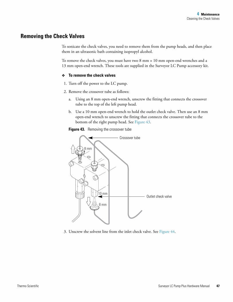
4 MaintenanceCleaning the Check Valves
Removing the Check Valves
To sonicate the check valves, you need to remove them from the pump heads, and then place them in an ultrasonic bath containing isopropyl alcohol.
To remove the check valves, you must have two 8 mm × 10 mm open-end wrenches and a 13 mm open-end wrench. These tools are supplied in the Surveyor LC Pump accessory kit.
To remove the check valves
1. Turn off the power to the LC pump.
2. Remove the crossover tube as follows:
a. Using an 8 mm open-end wrench, unscrew the fitting that connects the crossover tube to the top of the left pump head.
b. Use a 10 mm open-end wrench to hold the outlet check valve. Then use an 8 mm open-end wrench to unscrew the fitting that connects the crossover tube to the bottom of the right pump head. See Figure 43.
Figure 43. Removing the crossover tube
3. Unscrew the solvent line from the inlet check valve. See Figure 44.
8 mm
8 mm
10 mm
Crossover tube
Outlet check valve
Thermo Scientific Surveyor LC Pump Plus Hardware Manual 47
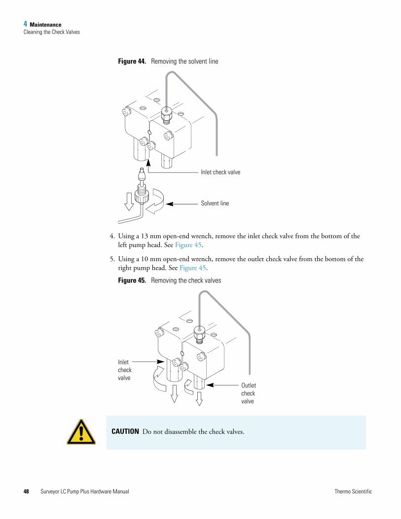
4 MaintenanceCleaning the Check Valves
48
Figure 44. Removing the solvent line
4. Using a 13 mm open-end wrench, remove the inlet check valve from the bottom of the left pump head. See Figure 45.
5. Using a 10 mm open-end wrench, remove the outlet check valve from the bottom of the right pump head. See Figure 45.
Figure 45. Removing the check valves
Inlet check valve
Solvent line
Inletcheckvalve
Outletcheckvalve
CAUTION Do not disassemble the check valves.
Surveyor LC Pump Plus Hardware Manual Thermo Scientific
4 MaintenanceCleaning the Check Valves
Sonicating the Check Valves
After you remove the check valves from the pump, clean them, and then reinstall them.
To clean the check valves
1. Put the inlet and outlet check valves in an ultrasonic bath filled with isopropyl alcohol. Sonicate them for approximately 5 minutes.
2. Remove the check valves from the bath.
Reinstalling the Check Valves
To reinstall the check valves
1. Screw the inlet check valves into the bottom of the left pump head. Using a 13 mm wrench, tighten the inlet check valve fitting.
2. Screw the outlet check valve into the bottom of the right pump head. Using a 10 mm wrench, tighten the outlet check valve fitting.
3. Re-attach the crossover tube to the top of the left pump head. Using an 8 mm open-end wrench, tighten the fitting.
4. Re-attach the other end of the crossover tube to the outlet check valve. Use the 10 mm open-end wrench to hold the outlet check valve, and then tighten the fitting with an 8 mm open-end wrench.
5. Re-attach the solvent line.
6. Turn the power to the pump back on.
7. Purge air from the pump heads and solvent lines (see “Purging Air from the Solvent Lines or the Pump Heads” on page 67).
8. Retest the flow rate. If the liquid does not flow continuously from the drain tube, replace the check valves.
Thermo Scientific Surveyor LC Pump Plus Hardware Manual 49
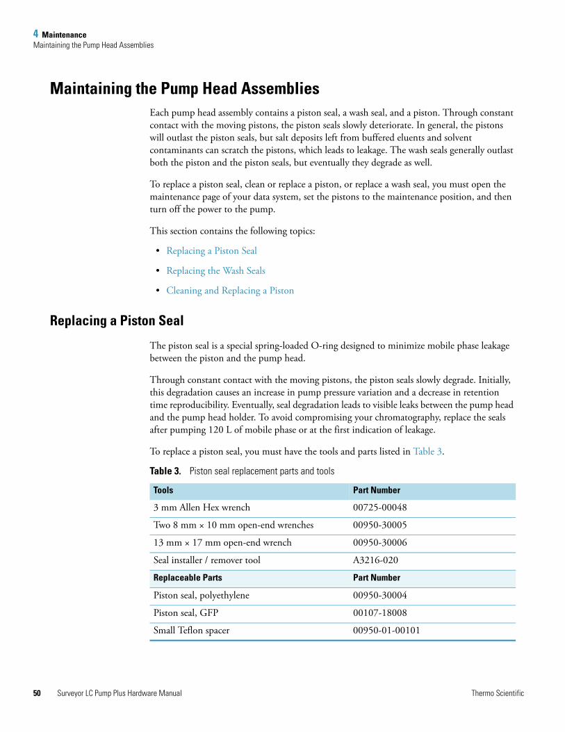
4 MaintenanceMaintaining the Pump Head Assemblies
50
Maintaining the Pump Head AssembliesEach pump head assembly contains a piston seal, a wash seal, and a piston. Through constant contact with the moving pistons, the piston seals slowly deteriorate. In general, the pistons will outlast the piston seals, but salt deposits left from buffered eluents and solvent contaminants can scratch the pistons, which leads to leakage. The wash seals generally outlast both the piston and the piston seals, but eventually they degrade as well.
To replace a piston seal, clean or replace a piston, or replace a wash seal, you must open the maintenance page of your data system, set the pistons to the maintenance position, and then turn off the power to the pump.
This section contains the following topics:
• Replacing a Piston Seal
• Replacing the Wash Seals
• Cleaning and Replacing a Piston
Replacing a Piston Seal
The piston seal is a special spring-loaded O-ring designed to minimize mobile phase leakage between the piston and the pump head.
Through constant contact with the moving pistons, the piston seals slowly degrade. Initially, this degradation causes an increase in pump pressure variation and a decrease in retention time reproducibility. Eventually, seal degradation leads to visible leaks between the pump head and the pump head holder. To avoid compromising your chromatography, replace the seals after pumping 120 L of mobile phase or at the first indication of leakage.
To replace a piston seal, you must have the tools and parts listed in Table 3.
Table 3. Piston seal replacement parts and tools
Tools Part Number
3 mm Allen Hex wrench 00725-00048
Two 8 mm × 10 mm open-end wrenches 00950-30005
13 mm × 17 mm open-end wrench 00950-30006
Seal installer / remover tool A3216-020
Replaceable Parts Part Number
Piston seal, polyethylene 00950-30004
Piston seal, GFP 00107-18008
Small Teflon spacer 00950-01-00101
Surveyor LC Pump Plus Hardware Manual Thermo Scientific
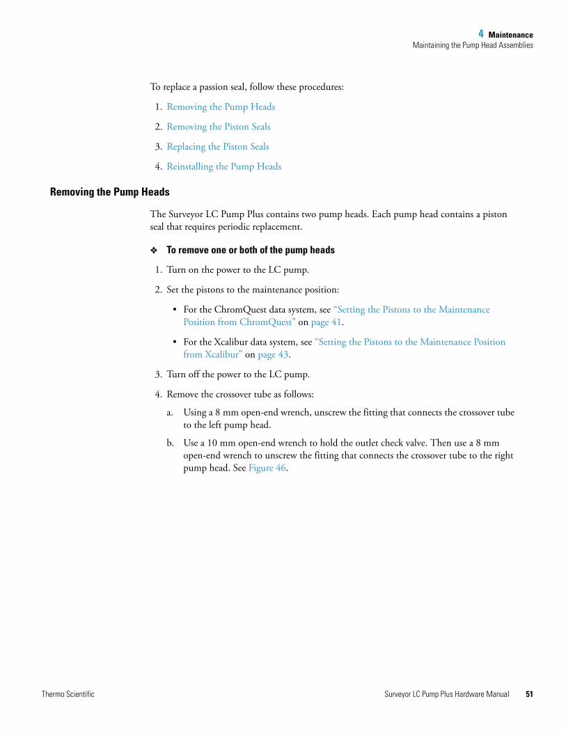
4 MaintenanceMaintaining the Pump Head Assemblies
To replace a passion seal, follow these procedures:
1. Removing the Pump Heads
2. Removing the Piston Seals
3. Replacing the Piston Seals
4. Reinstalling the Pump Heads
Removing the Pump Heads
The Surveyor LC Pump Plus contains two pump heads. Each pump head contains a piston seal that requires periodic replacement.
To remove one or both of the pump heads
1. Turn on the power to the LC pump.
2. Set the pistons to the maintenance position:
• For the ChromQuest data system, see “Setting the Pistons to the Maintenance Position from ChromQuest” on page 41.
• For the Xcalibur data system, see “Setting the Pistons to the Maintenance Position from Xcalibur” on page 43.
3. Turn off the power to the LC pump.
4. Remove the crossover tube as follows:
a. Using a 8 mm open-end wrench, unscrew the fitting that connects the crossover tube to the left pump head.
b. Use a 10 mm open-end wrench to hold the outlet check valve. Then use a 8 mm open-end wrench to unscrew the fitting that connects the crossover tube to the right pump head. See Figure 46.
Thermo Scientific Surveyor LC Pump Plus Hardware Manual 51
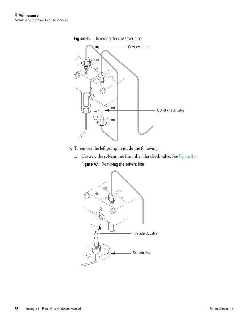
4 MaintenanceMaintaining the Pump Head Assemblies
52
Figure 46. Removing the crossover tube
5. To remove the left pump head, do the following:
a. Unscrew the solvent line from the inlet check valve. See Figure 47.
Figure 47. Removing the solvent line
8 mm
8 mm
10 mm
Crossover tube
Outlet check valve
Inlet check valve
Solvent line
Surveyor LC Pump Plus Hardware Manual Thermo Scientific
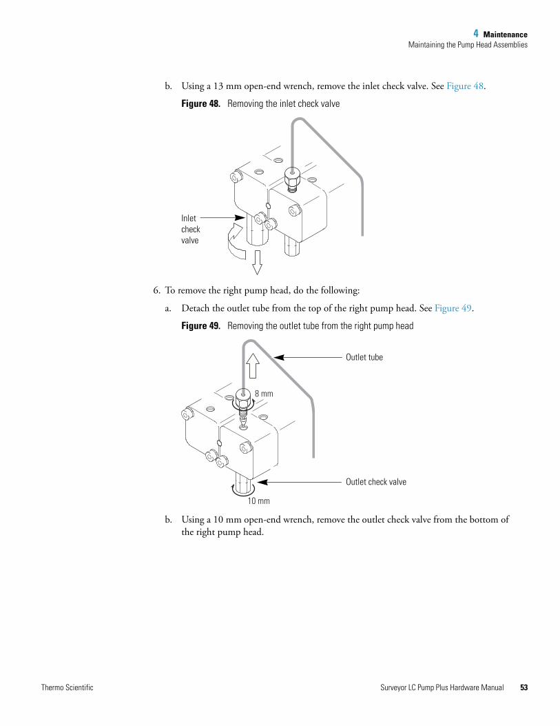
4 MaintenanceMaintaining the Pump Head Assemblies
b. Using a 13 mm open-end wrench, remove the inlet check valve. See Figure 48.
Figure 48. Removing the inlet check valve
6. To remove the right pump head, do the following:
a. Detach the outlet tube from the top of the right pump head. See Figure 49.
Figure 49. Removing the outlet tube from the right pump head
b. Using a 10 mm open-end wrench, remove the outlet check valve from the bottom of the right pump head.
Inletcheckvalve
8 mm
10 mm
Outlet check valve
Outlet tube
Thermo Scientific Surveyor LC Pump Plus Hardware Manual 53
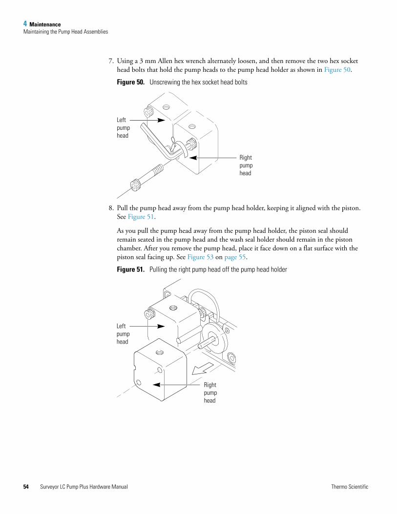
4 MaintenanceMaintaining the Pump Head Assemblies
54
7. Using a 3 mm Allen hex wrench alternately loosen, and then remove the two hex socket head bolts that hold the pump heads to the pump head holder as shown in Figure 50.
Figure 50. Unscrewing the hex socket head bolts
8. Pull the pump head away from the pump head holder, keeping it aligned with the piston. See Figure 51.
As you pull the pump head away from the pump head holder, the piston seal should remain seated in the pump head and the wash seal holder should remain in the piston chamber. After you remove the pump head, place it face down on a flat surface with the piston seal facing up. See Figure 53 on page 55.
Figure 51. Pulling the right pump head off the pump head holder
Leftpumphead
Rightpumphead
Leftpumphead
Rightpumphead
Surveyor LC Pump Plus Hardware Manual Thermo Scientific
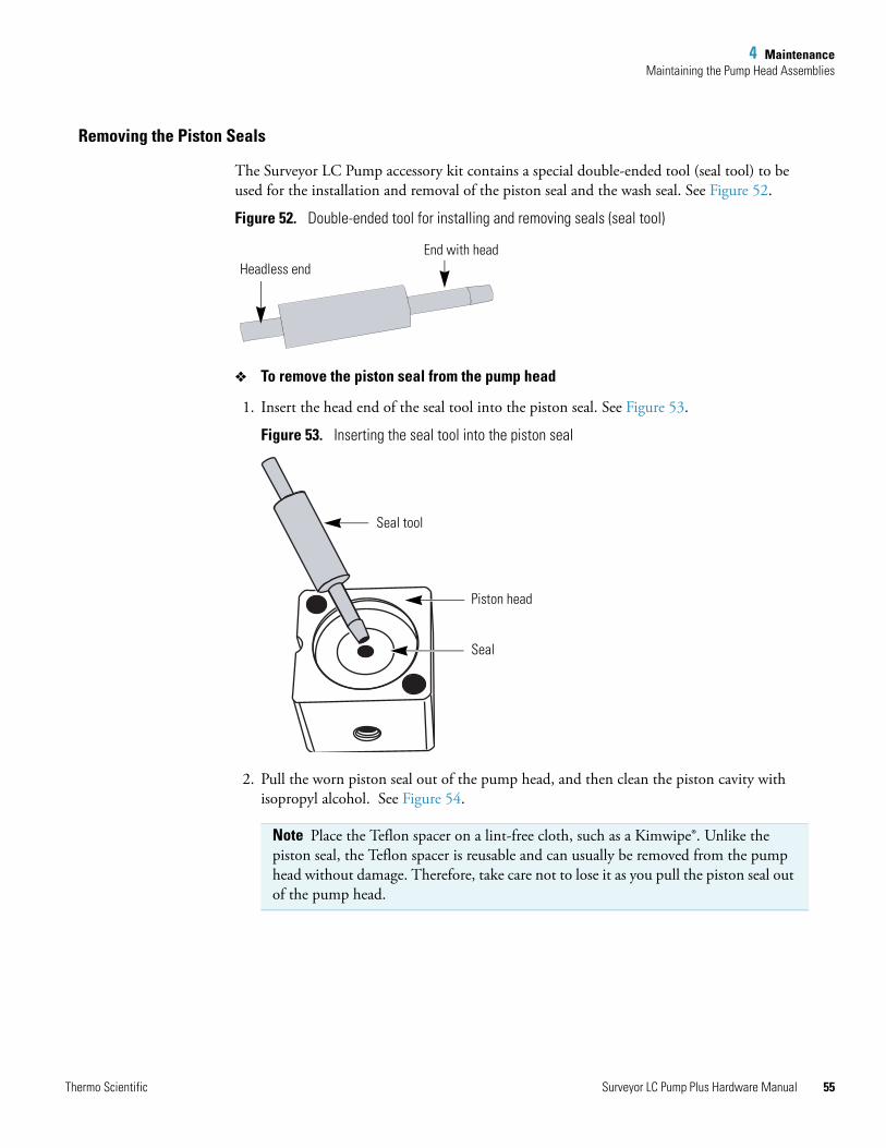
4 MaintenanceMaintaining the Pump Head Assemblies
Removing the Piston Seals
The Surveyor LC Pump accessory kit contains a special double-ended tool (seal tool) to be used for the installation and removal of the piston seal and the wash seal. See Figure 52.
Figure 52. Double-ended tool for installing and removing seals (seal tool)
To remove the piston seal from the pump head
1. Insert the head end of the seal tool into the piston seal. See Figure 53.
Figure 53. Inserting the seal tool into the piston seal
2. Pull the worn piston seal out of the pump head, and then clean the piston cavity with isopropyl alcohol. See Figure 54.
Note Place the Teflon spacer on a lint-free cloth, such as a Kimwipe®. Unlike the piston seal, the Teflon spacer is reusable and can usually be removed from the pump head without damage. Therefore, take care not to lose it as you pull the piston seal out of the pump head.
Headless endEnd with head
Seal tool
Seal
Piston head
Thermo Scientific Surveyor LC Pump Plus Hardware Manual 55
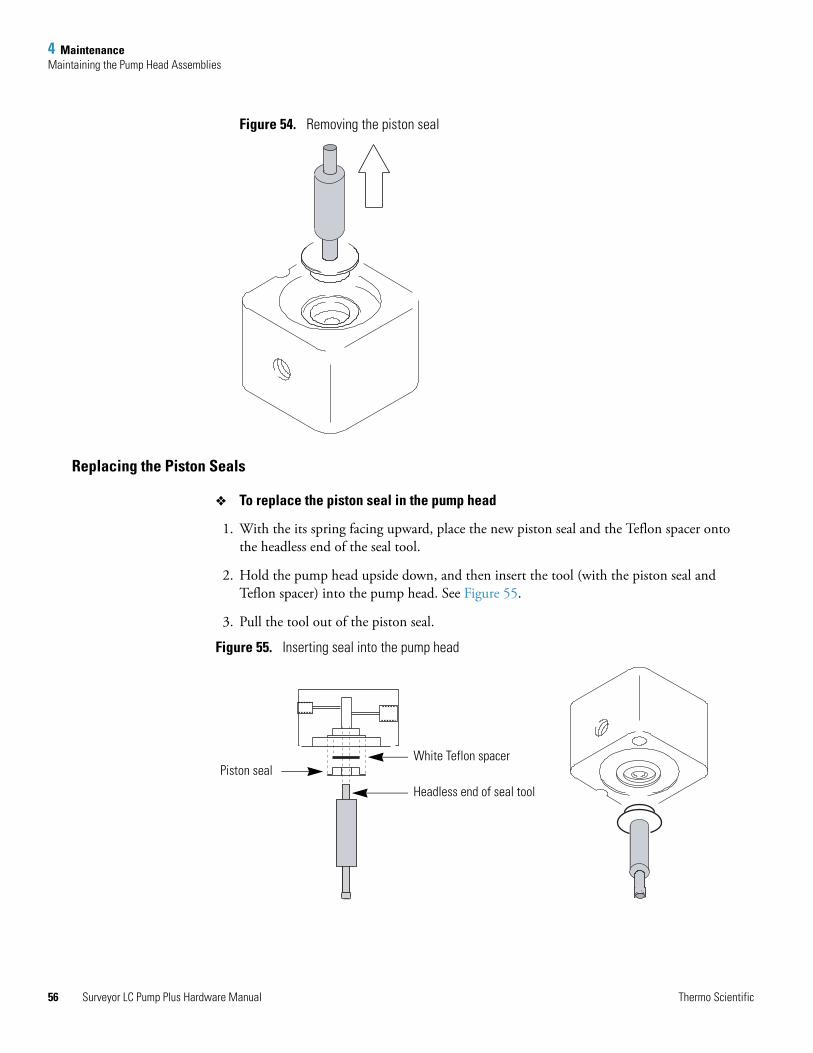
4 MaintenanceMaintaining the Pump Head Assemblies
56
Figure 54. Removing the piston seal
Replacing the Piston Seals
To replace the piston seal in the pump head
1. With the its spring facing upward, place the new piston seal and the Teflon spacer onto the headless end of the seal tool.
2. Hold the pump head upside down, and then insert the tool (with the piston seal and Teflon spacer) into the pump head. See Figure 55.
3. Pull the tool out of the piston seal.
Figure 55. Inserting seal into the pump head
White Teflon spacer
Headless end of seal tool
Piston seal
Surveyor LC Pump Plus Hardware Manual Thermo Scientific
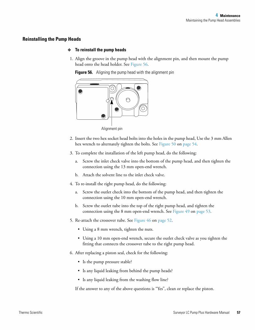
4 MaintenanceMaintaining the Pump Head Assemblies
Reinstalling the Pump Heads
To reinstall the pump heads
1. Align the groove in the pump head with the alignment pin, and then mount the pump head onto the head holder. See Figure 56.
Figure 56. Aligning the pump head with the alignment pin
2. Insert the two hex socket head bolts into the holes in the pump head, Use the 3 mm Allen hex wrench to alternately tighten the bolts. See Figure 50 on page 54.
3. To complete the installation of the left pump head, do the following:
a. Screw the inlet check valve into the bottom of the pump head, and then tighten the connection using the 13 mm open-end wrench.
b. Attach the solvent line to the inlet check valve.
4. To re-install the right pump head, do the following:
a. Screw the outlet check into the bottom of the pump head, and then tighten the connection using the 10 mm open-end wrench.
b. Screw the outlet tube into the top of the right pump head, and tighten the connection using the 8 mm open-end wrench. See Figure 49 on page 53.
5. Re-attach the crossover tube. See Figure 46 on page 52.
• Using a 8 mm wrench, tighten the nuts.
• Using a 10 mm open-end wrench, secure the outlet check valve as you tighten the fitting that connects the crossover tube to the right pump head.
6. After replacing a piston seal, check for the following:
• Is the pump pressure stable?
• Is any liquid leaking from behind the pump heads?
• Is any liquid leaking from the washing flow line?
If the answer to any of the above questions is “Yes”, clean or replace the piston.
Alignment pin
Thermo Scientific Surveyor LC Pump Plus Hardware Manual 57
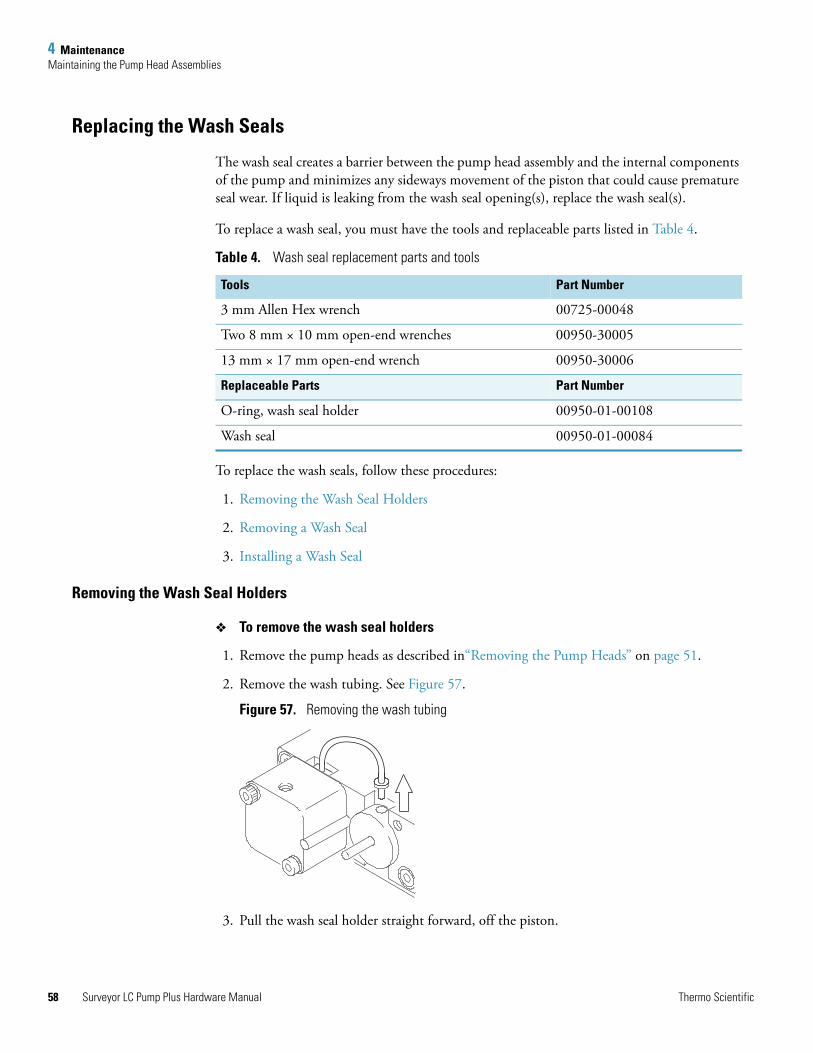
4 MaintenanceMaintaining the Pump Head Assemblies
58
Replacing the Wash Seals
The wash seal creates a barrier between the pump head assembly and the internal components of the pump and minimizes any sideways movement of the piston that could cause premature seal wear. If liquid is leaking from the wash seal opening(s), replace the wash seal(s).
To replace a wash seal, you must have the tools and replaceable parts listed in Table 4.
To replace the wash seals, follow these procedures:
1. Removing the Wash Seal Holders
2. Removing a Wash Seal
3. Installing a Wash Seal
Removing the Wash Seal Holders
To remove the wash seal holders
1. Remove the pump heads as described in“Removing the Pump Heads” on page 51.
2. Remove the wash tubing. See Figure 57.
Figure 57. Removing the wash tubing
3. Pull the wash seal holder straight forward, off the piston.
Table 4. Wash seal replacement parts and tools
Tools Part Number
3 mm Allen Hex wrench 00725-00048
Two 8 mm × 10 mm open-end wrenches 00950-30005
13 mm × 17 mm open-end wrench 00950-30006
Replaceable Parts Part Number
O-ring, wash seal holder 00950-01-00108
Wash seal 00950-01-00084
Surveyor LC Pump Plus Hardware Manual Thermo Scientific
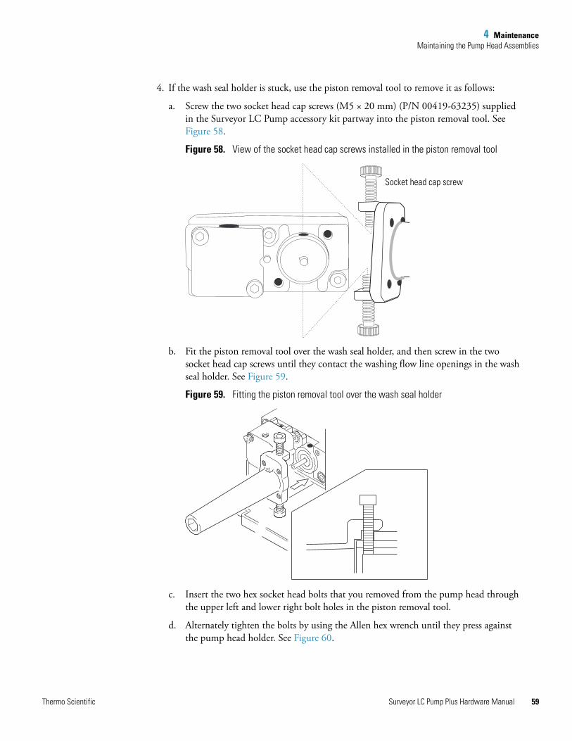
4 MaintenanceMaintaining the Pump Head Assemblies
4. If the wash seal holder is stuck, use the piston removal tool to remove it as follows:
a. Screw the two socket head cap screws (M5 × 20 mm) (P/N 00419-63235) supplied in the Surveyor LC Pump accessory kit partway into the piston removal tool. See Figure 58.
Figure 58. View of the socket head cap screws installed in the piston removal tool
b. Fit the piston removal tool over the wash seal holder, and then screw in the two socket head cap screws until they contact the washing flow line openings in the wash seal holder. See Figure 59.
Figure 59. Fitting the piston removal tool over the wash seal holder
c. Insert the two hex socket head bolts that you removed from the pump head through the upper left and lower right bolt holes in the piston removal tool.
d. Alternately tighten the bolts by using the Allen hex wrench until they press against the pump head holder. See Figure 60.
Socket head cap screw
Thermo Scientific Surveyor LC Pump Plus Hardware Manual 59
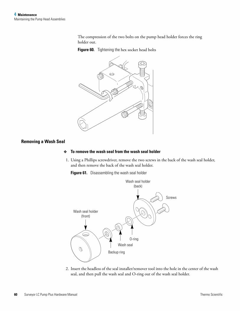
4 MaintenanceMaintaining the Pump Head Assemblies
60
The compression of the two bolts on the pump head holder forces the ring holder out.
Figure 60. Tightening the hex socket head bolts
Removing a Wash Seal
To remove the wash seal from the wash seal holder
1. Using a Phillips screwdriver, remove the two screws in the back of the wash seal holder, and then remove the back of the wash seal holder.
Figure 61. Disassembling the wash seal holder
2. Insert the headless of the seal installer/remover tool into the hole in the center of the wash seal, and then pull the wash seal and O-ring out of the wash seal holder.
Backup ring
Wash seal holder(front)
Wash seal holder(back)
Wash seal
O-ring
Screws
Surveyor LC Pump Plus Hardware Manual Thermo Scientific
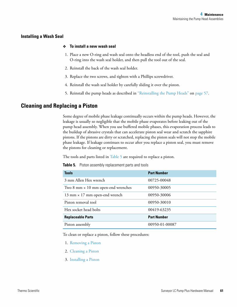
4 MaintenanceMaintaining the Pump Head Assemblies
Installing a Wash Seal
To install a new wash seal
1. Place a new O-ring and wash seal onto the headless end of the tool, push the seal and O-ring into the wash seal holder, and then pull the tool out of the seal.
2. Reinstall the back of the wash seal holder.
3. Replace the two screws, and tighten with a Phillips screwdriver.
4. Reinstall the wash seal holder by carefully sliding it over the piston.
5. Reinstall the pump heads as described in “Reinstalling the Pump Heads” on page 57.
Cleaning and Replacing a Piston
Some degree of mobile phase leakage continually occurs within the pump heads. However, the leakage is usually so negligible that the mobile phase evaporates before leaking out of the pump head assembly. When you use buffered mobile phases, this evaporation process leads to the buildup of abrasive crystals that can accelerate piston seal wear and scratch the sapphire pistons. If the pistons are dirty or scratched, replacing the piston seals will not stop the mobile phase leakage. If leakage continues to occur after you replace a piston seal, you must remove the pistons for cleaning or replacement.
The tools and parts listed in Table 5 are required to replace a piston.
To clean or replace a piston, follow these procedures:
1. Removing a Piston
2. Cleaning a Piston
3. Installing a Piston
Table 5. Piston assembly replacement parts and tools
Tools Part Number
3 mm Allen Hex wrench 00725-00048
Two 8 mm × 10 mm open-end wrenches 00950-30005
13 mm × 17 mm open-end wrench 00950-30006
Piston removal tool 00950-30010
Hex socket head bolts 00419-63235
Replaceable Parts Part Number
Piston assembly 00950-01-00087
Thermo Scientific Surveyor LC Pump Plus Hardware Manual 61
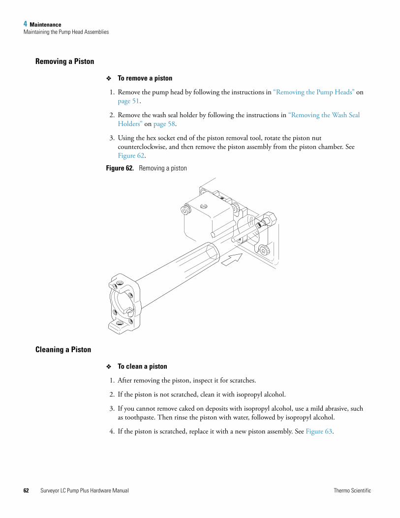
4 MaintenanceMaintaining the Pump Head Assemblies
62
Removing a Piston
To remove a piston
1. Remove the pump head by following the instructions in “Removing the Pump Heads” on page 51.
2. Remove the wash seal holder by following the instructions in “Removing the Wash Seal Holders” on page 58.
3. Using the hex socket end of the piston removal tool, rotate the piston nut counterclockwise, and then remove the piston assembly from the piston chamber. See Figure 62.
Figure 62. Removing a piston
Cleaning a Piston
To clean a piston
1. After removing the piston, inspect it for scratches.
2. If the piston is not scratched, clean it with isopropyl alcohol.
3. If you cannot remove caked on deposits with isopropyl alcohol, use a mild abrasive, such as toothpaste. Then rinse the piston with water, followed by isopropyl alcohol.
4. If the piston is scratched, replace it with a new piston assembly. See Figure 63.
Surveyor LC Pump Plus Hardware Manual Thermo Scientific
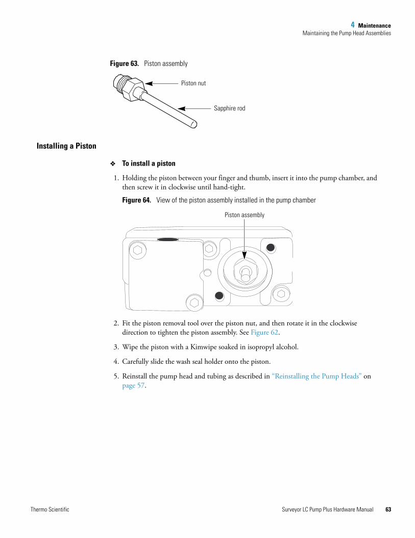
4 MaintenanceMaintaining the Pump Head Assemblies
Figure 63. Piston assembly
Installing a Piston
To install a piston
1. Holding the piston between your finger and thumb, insert it into the pump chamber, and then screw it in clockwise until hand-tight.
Figure 64. View of the piston assembly installed in the pump chamber
2. Fit the piston removal tool over the piston nut, and then rotate it in the clockwise direction to tighten the piston assembly. See Figure 62.
3. Wipe the piston with a Kimwipe soaked in isopropyl alcohol.
4. Carefully slide the wash seal holder onto the piston.
5. Reinstall the pump head and tubing as described in “Reinstalling the Pump Heads” on page 57.
Piston nut
Sapphire rod
Piston assembly
Thermo Scientific Surveyor LC Pump Plus Hardware Manual 63
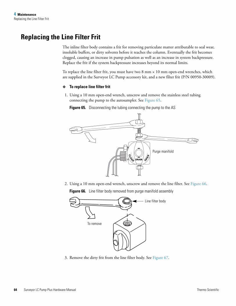
4 MaintenanceReplacing the Line Filter Frit
64
Replacing the Line Filter FritThe inline filter body contains a frit for removing particulate matter attributable to seal wear, insoluble buffers, or dirty solvents before it reaches the column. Eventually the frit becomes clogged, causing an increase in pump pulsation as well as an increase in system backpressure. Replace the frit if the system backpressure increases beyond its normal limits.
To replace the line filter frit, you must have two 8 mm × 10 mm open-end wrenches, which are supplied in the Surveyor LC Pump accessory kit, and a new filter frit (P/N 00950-30009).
To replace line filter frit
1. Using a 10 mm open-end wrench, unscrew and remove the stainless steel tubing connecting the pump to the autosampler. See Figure 65.
Figure 65. Disconnecting the tubing connecting the pump to the AS
2. Using a 10 mm open-end wrench, unscrew and remove the line filter. See Figure 66.
Figure 66. Line filter body removed from purge manifold assembly
3. Remove the dirty frit from the line filter body. See Figure 67.
DRAINDRAIN
CLO
S E OPEN
Purge manifold
Line filter body
To remove
Surveyor LC Pump Plus Hardware Manual Thermo Scientific
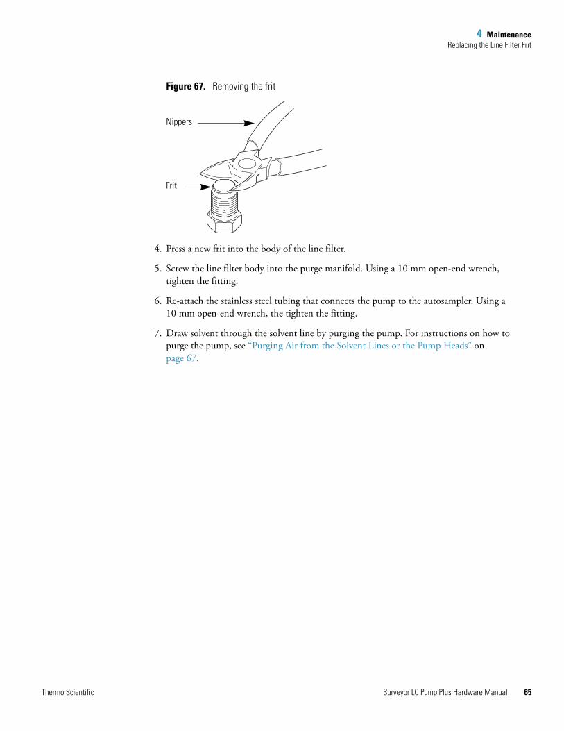
4 MaintenanceReplacing the Line Filter Frit
Figure 67. Removing the frit
4. Press a new frit into the body of the line filter.
5. Screw the line filter body into the purge manifold. Using a 10 mm open-end wrench, tighten the fitting.
6. Re-attach the stainless steel tubing that connects the pump to the autosampler. Using a 10 mm open-end wrench, the tighten the fitting.
7. Draw solvent through the solvent line by purging the pump. For instructions on how to purge the pump, see “Purging Air from the Solvent Lines or the Pump Heads” on page 67.
Nippers
Frit
Thermo Scientific Surveyor LC Pump Plus Hardware Manual 65
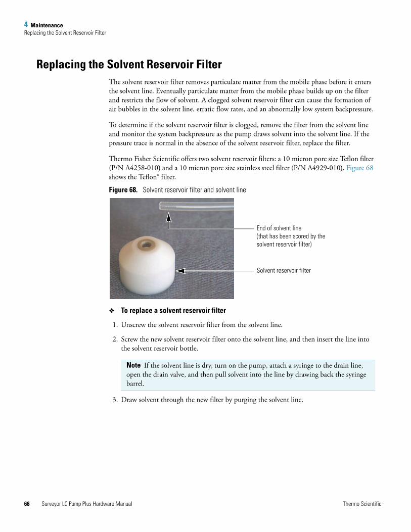
4 MaintenanceReplacing the Solvent Reservoir Filter
66
Replacing the Solvent Reservoir Filter The solvent reservoir filter removes particulate matter from the mobile phase before it enters the solvent line. Eventually particulate matter from the mobile phase builds up on the filter and restricts the flow of solvent. A clogged solvent reservoir filter can cause the formation of air bubbles in the solvent line, erratic flow rates, and an abnormally low system backpressure.
To determine if the solvent reservoir filter is clogged, remove the filter from the solvent line and monitor the system backpressure as the pump draws solvent into the solvent line. If the pressure trace is normal in the absence of the solvent reservoir filter, replace the filter.
Thermo Fisher Scientific offers two solvent reservoir filters: a 10 micron pore size Teflon filter (P/N A4258-010) and a 10 micron pore size stainless steel filter (P/N A4929-010). Figure 68 shows the Teflon® filter.
Figure 68. Solvent reservoir filter and solvent line
To replace a solvent reservoir filter
1. Unscrew the solvent reservoir filter from the solvent line.
2. Screw the new solvent reservoir filter onto the solvent line, and then insert the line into the solvent reservoir bottle.
3. Draw solvent through the new filter by purging the solvent line.
Note If the solvent line is dry, turn on the pump, attach a syringe to the drain line, open the drain valve, and then pull solvent into the line by drawing back the syringe barrel.
End of solvent line(that has been scored by the solvent reservoir filter)
Solvent reservoir filter
Surveyor LC Pump Plus Hardware Manual Thermo Scientific
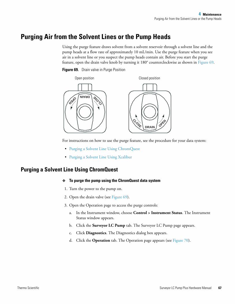
4 MaintenancePurging Air from the Solvent Lines or the Pump Heads
Purging Air from the Solvent Lines or the Pump HeadsUsing the purge feature draws solvent from a solvent reservoir through a solvent line and the pump heads at a flow rate of approximately 10 mL/min. Use the purge feature when you see air in a solvent line or you suspect the pump heads contain air. Before you start the purge feature, open the drain valve knob by turning it 180° counterclockwise as shown in Figure 69.
Figure 69. Drain valve in Purge Position
For instructions on how to use the purge feature, see the procedure for your data system:
• Purging a Solvent Line Using ChromQuest
• Purging a Solvent Line Using Xcalibur
Purging a Solvent Line Using ChromQuest
To purge the pump using the ChromQuest data system
1. Turn the power to the pump on.
2. Open the drain valve (see Figure 69).
3. Open the Operation page to access the purge controls:
a. In the Instrument window, choose Control > Instrument Status. The Instrument Status window appears.
b. Click the Surveyor LC Pump tab. The Surveyor LC Pump page appears.
c. Click Diagnostics. The Diagnostics dialog box appears.
d. Click the Operation tab. The Operation page appears (see Figure 70).
DRAIN
CLOSE OPEN
DRAIN
CLOSEOPEN
Open position Closed position
Thermo Scientific Surveyor LC Pump Plus Hardware Manual 67
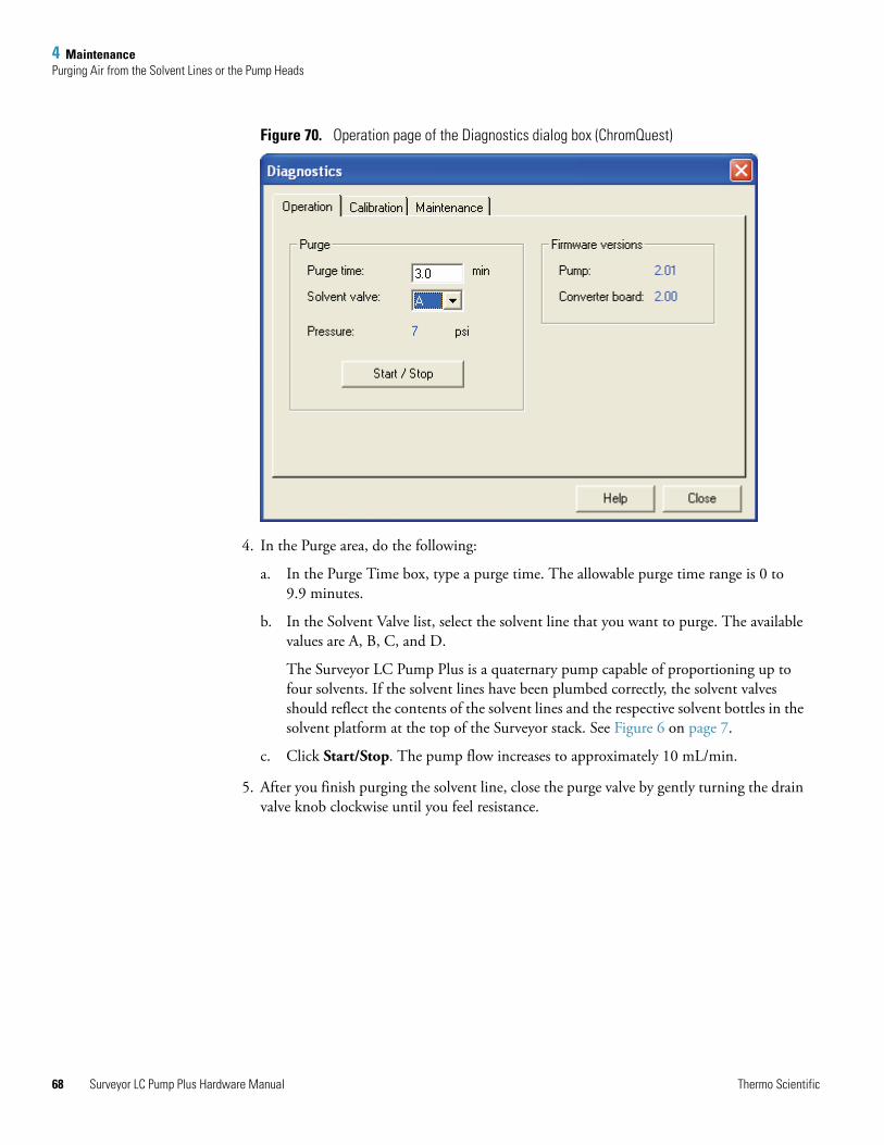
4 MaintenancePurging Air from the Solvent Lines or the Pump Heads
68
Figure 70. Operation page of the Diagnostics dialog box (ChromQuest)
4. In the Purge area, do the following:
a. In the Purge Time box, type a purge time. The allowable purge time range is 0 to 9.9 minutes.
b. In the Solvent Valve list, select the solvent line that you want to purge. The available values are A, B, C, and D.
The Surveyor LC Pump Plus is a quaternary pump capable of proportioning up to four solvents. If the solvent lines have been plumbed correctly, the solvent valves should reflect the contents of the solvent lines and the respective solvent bottles in the solvent platform at the top of the Surveyor stack. See Figure 6 on page 7.
c. Click Start/Stop. The pump flow increases to approximately 10 mL/min.
5. After you finish purging the solvent line, close the purge valve by gently turning the drain valve knob clockwise until you feel resistance.
Surveyor LC Pump Plus Hardware Manual Thermo Scientific
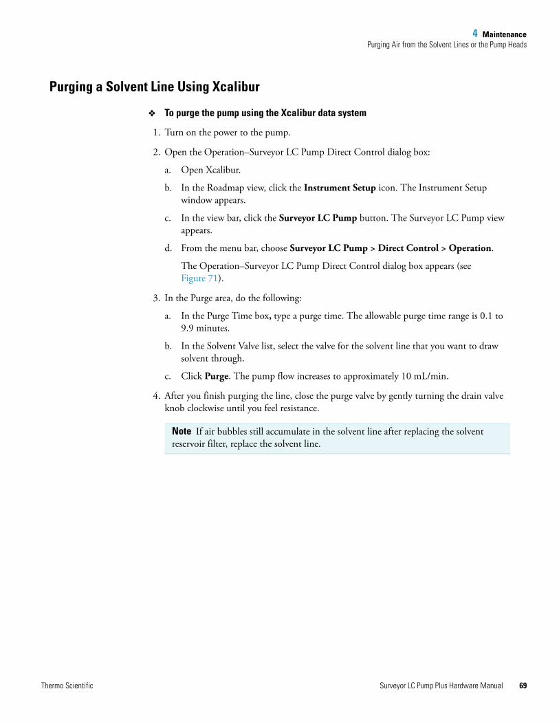
4 MaintenancePurging Air from the Solvent Lines or the Pump Heads
Purging a Solvent Line Using Xcalibur
To purge the pump using the Xcalibur data system
1. Turn on the power to the pump.
2. Open the Operation–Surveyor LC Pump Direct Control dialog box:
a. Open Xcalibur.
b. In the Roadmap view, click the Instrument Setup icon. The Instrument Setup window appears.
c. In the view bar, click the Surveyor LC Pump button. The Surveyor LC Pump view appears.
d. From the menu bar, choose Surveyor LC Pump > Direct Control > Operation.
The Operation–Surveyor LC Pump Direct Control dialog box appears (see Figure 71).
3. In the Purge area, do the following:
a. In the Purge Time box, type a purge time. The allowable purge time range is 0.1 to 9.9 minutes.
b. In the Solvent Valve list, select the valve for the solvent line that you want to draw solvent through.
c. Click Purge. The pump flow increases to approximately 10 mL/min.
4. After you finish purging the line, close the purge valve by gently turning the drain valve knob clockwise until you feel resistance.
Note If air bubbles still accumulate in the solvent line after replacing the solvent reservoir filter, replace the solvent line.
Thermo Scientific Surveyor LC Pump Plus Hardware Manual 69
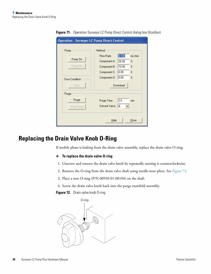
4 MaintenanceReplacing the Drain Valve Knob O-Ring
70
Figure 71. Operation Surveyor LC Pump Direct Control dialog box (Xcalibur)
Replacing the Drain Valve Knob O-RingIf mobile phase is leaking from the drain valve assembly, replace the drain valve O-ring.
To replace the drain valve O-ring
1. Unscrew and remove the drain valve knob by repeatedly turning it counterclockwise.
2. Remove the O-ring from the drain valve shaft using needle-nose pliers. See Figure 72.
3. Place a new O-ring (P/N 00950-01-00104) on the shaft.
4. Screw the drain valve knob back into the purge manifold assembly.
Figure 72. Drain valve knob O-ring
O-ring
Surveyor LC Pump Plus Hardware Manual Thermo Scientific
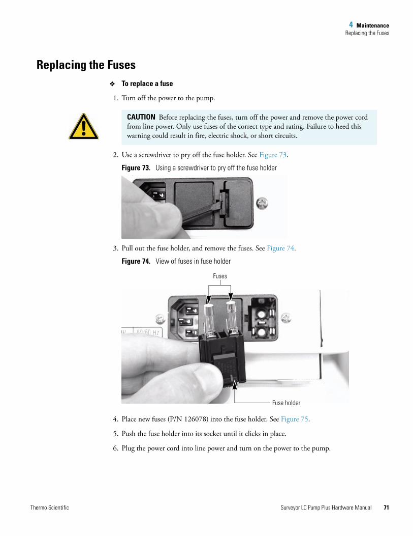
4 MaintenanceReplacing the Fuses
Replacing the FusesTo replace a fuse
1. Turn off the power to the pump.
2. Use a screwdriver to pry off the fuse holder. See Figure 73.
Figure 73. Using a screwdriver to pry off the fuse holder
3. Pull out the fuse holder, and remove the fuses. See Figure 74.
Figure 74. View of fuses in fuse holder
4. Place new fuses (P/N 126078) into the fuse holder. See Figure 75.
5. Push the fuse holder into its socket until it clicks in place.
6. Plug the power cord into line power and turn on the power to the pump.
CAUTION Before replacing the fuses, turn off the power and remove the power cord from line power. Only use fuses of the correct type and rating. Failure to heed this warning could result in fire, electric shock, or short circuits.
Fuses
Fuse holder
Thermo Scientific Surveyor LC Pump Plus Hardware Manual 71
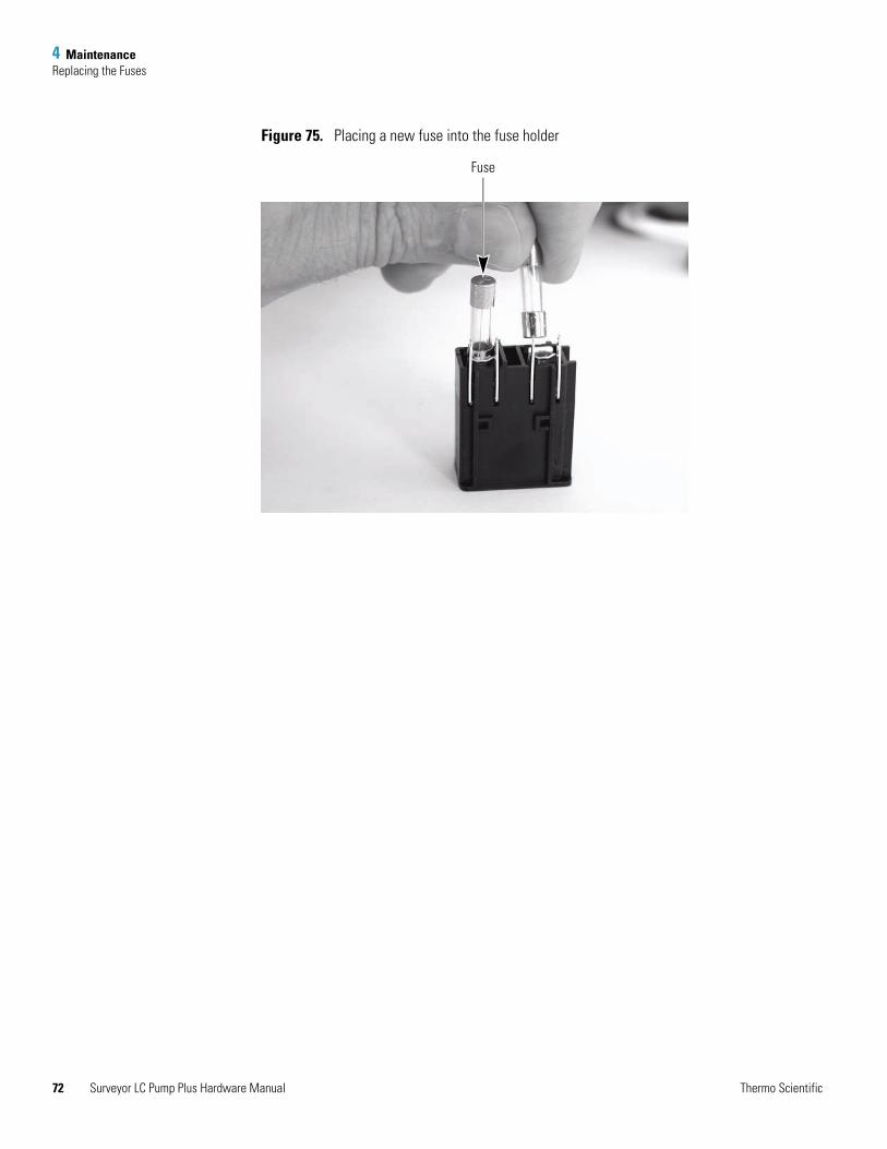
4 MaintenanceReplacing the Fuses
72
Figure 75. Placing a new fuse into the fuse holder
Fuse
Surveyor LC Pump Plus Hardware Manual Thermo Scientific
5
Diagnostic Tests and Calibration Procedures
This chapter contains instructions for performing the following diagnostic tests that will ensure the transferability of your methods:
The Calibration topic of this chapter contains instructions for performing the following calibration procedures:
• Compressibility
• Pressure Recorder Full Scale
• Flow Rate Adjustment (Alpha)
• Pressure Sensor Adjustment
• Pressure Transducer Zero
Contents
• Flow Rate Accuracy Check
• Pressure Pulsation Check
• Proportioning Accuracy Check
• Gradient Delay Volume Check
• Calibration
Thermo Scientific Surveyor LC Pump Plus Hardware Manual 73
5 Diagnostic Tests and Calibration ProceduresFlow Rate Accuracy Check
74
Flow Rate Accuracy CheckThe flow rate accuracy of your LC pump is an important variable if you are developing analytical methods that will be transferred to other instruments.
The flow rate accuracy of the LC pump is determined by comparing the actual flow rate to the set rate. The actual flow rate of the LC pump is determined by measuring the volume of water pumped in a measured length of time.
To perform a flow rate accuracy check, you need the following items:
• HPLC-grade water
• Column or backpressure regulator that produces a backpressure of 2.9 to 9.8 MPa (420 to 1420 psi) at a flow rate of 1.0 mL/min
• 10 mL graduated cylinder to measure volume
• Analytical balance (optional) to indirectly measure volume
• Stopwatch to measure elapsed time
To perform a flow rate accuracy check
1. (Optional) Weigh the empty 10 mL graduated cylinder and record the weight.
2. Set up the instrument to pump water at a flow rate of 1 mL/min:
a. Fill the solvent reservoir with distilled water, and then purge the line to remove the former mobile phase.
b. Disconnect the column or backpressure regulator from the detector.
c. Pump water through the column or the backpressure regulator to remove the former mobile phase.
d. Change the compressibility setting to 0.45—the compressibility ratio for water.
Note You can determine the volume of the water that you collect in the graduated cylinder by estimating the level of the meniscus. However, if you need a more accurate measurement for the flow rate, determine the volume of the water that you collect in the graduated cylinder from the difference between the weight of the empty cylinder and the weight of the cylinder filled with approximately 10 mL of water.
Note You must enter the compressibility ratio for the solvent that you are using. Water is the recommended solvent for testing flow rate accuracy.
Surveyor LC Pump Plus Hardware Manual Thermo Scientific
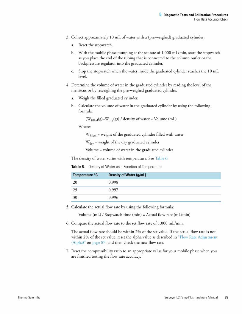
5 Diagnostic Tests and Calibration ProceduresFlow Rate Accuracy Check
3. Collect approximately 10 mL of water with a (pre-weighed) graduated cylinder:
a. Reset the stopwatch.
b. With the mobile phase pumping at the set rate of 1.000 mL/min, start the stopwatch as you place the end of the tubing that is connected to the column outlet or the backpressure regulator into the graduated cylinder.
c. Stop the stopwatch when the water inside the graduated cylinder reaches the 10 mL level.
4. Determine the volume of water in the graduated cylinder by reading the level of the meniscus or by reweighing the pre-weighed graduated cylinder:
a. Weigh the filled graduated cylinder.
b. Calculate the volume of water in the graduated cylinder by using the following formula:
(Wfilled(g)–Wdry(g)) / density of water = Volume (mL)
Where:
Wfilled = weight of the graduated cylinder filled with water
Wdry = weight of the dry graduated cylinder
Volume = volume of water in the graduated cylinder
The density of water varies with temperature. See Table 6.
5. Calculate the actual flow rate by using the following formula:
Volume (mL) / Stopwatch time (min) = Actual flow rate (mL/min)
6. Compare the actual flow rate to the set flow rate of 1.000 mL/min.
The actual flow rate should be within 2% of the set value. If the actual flow rate is not within 2% of the set value, reset the alpha value as described in “Flow Rate Adjustment (Alpha)” on page 87, and then check the new flow rate.
7. Reset the compressibility ratio to an appropriate value for your mobile phase when you are finished testing the flow rate accuracy.
Table 6. Density of Water as a Function of Temperature
Temperature °C Density of Water (g/mL)
20 0.998
25 0.997
30 0.996
Thermo Scientific Surveyor LC Pump Plus Hardware Manual 75
5 Diagnostic Tests and Calibration ProceduresPressure Pulsation Check
76
Pressure Pulsation CheckTypically, the Surveyor LC pump operates with less than 2% variation in the pressure pulsation at operating pressures from 29 to 100 bar (421 to 1450 psi). Periodically check the variation in pressure pulsation of your LC pump as a part of your pump maintenance program.
This topic contains these procedures:
• Checking the Pressure Pulsation of the LC Pump
• Troubleshooting the Cause of Excessive Pressure Variation
Checking the Pressure Pulsation of the LC Pump
To check the variation in pressure pulsation of your LC pump
1. Set up your instrument to pump water as follows:
a. Fill one of the solvent reservoir bottles with water.
b. If the solvent line is dry, attach a syringe to the drain line, open the drain valve, make sure that the pump power is on, and then draw the syringe barrel back pulling solvent into the line.
c. Purge the flow line connecting the solvent reservoir to the solvent proportioning valve until you replace the former solvent in the flow line with water.
d. Connect a column or backpressure regulator that produces a backpressure of 29 to 100 bar (420 to 1450 psi) at a flow rate of 1.0 mL/min to the pump outlet.
2. Change the compressibility setting to 0.45—the compressibility ratio for water.
3. Pump water at a flow rate of 1.0 mL/min.
4. Monitor the pressure variation.
Troubleshooting the Cause of Excessive Pressure Variation
A number of factors can cause the maximum pressure variation to increase. The most frequently occurring problems are as follows:
• Solvent leaks from piston seals
• Air bubbles inside the pump head
• Contamination in the check valves
• Contamination in the proportioning valves
If the pressure pulsation of the pump is greater than 2% at operating pressures from 29 to 100 bar, you need to determine the cause of the problem.
Surveyor LC Pump Plus Hardware Manual Thermo Scientific

5 Diagnostic Tests and Calibration ProceduresProportioning Accuracy Check
T
To troubleshoot the cause of the excess variation in pressure
1. Visually inspect the pump for signs of leakage. Check for solvent leaks from the piston seals and or wash seals. If visible leaks are not present, proceed to step 2.
If you detect a leaking piston seal, replace it. See “Replacing a Piston Seal” on page 50. Visually inspect the piston for scratches or salt buildup. If the piston is dirty or scratched, clean it or replace it as described in “Cleaning and Replacing a Piston” on page 61. If you detect a leaking wash seal, replace it as described in “Replacing the Wash Seals” on page 58.
2. Check the flow rate accuracy. A slow leak behind the piston seal or trapped air bubbles in the pump head assemblies will cause a lower flow rate than the set rate, as well as an increase in pressure variation.
If trapped air in the piston chambers or the check valves is the suspected cause of the increased pressure variation, purge the pump with 100% methanol.
3. If a contaminated check valve is the suspected cause of the increased pressure variation, clean the check valves by pumping 100% isopropyl alcohol at a flow rate of 1 mL/min for a period of 1 hour.
4. If a contaminated proportioning valve is the suspected cause of the increased pressure variation, clean the pump by running it for 1 hour with 100% isopropyl alcohol on all four channels.
Proportioning Accuracy CheckThe proportioning accuracy of your pump is an important variable if you are developing analytical methods that will be transferred to other instruments.
Inaccuracies in proportioning can affect isocratic methods in which the solvent proportioning system delivers a blended mobile phase drawn from two or more solvent reservoir bottles. Inaccuracies in proportioning can also affect gradient methods in which the solvent proportioning system varies the percentage of two or more solvents during the run.
Test the proportioning accuracy of the pump periodically by running a step-gradient. The gradient program for testing proportioning accuracy is shown in Table 7. The gradient profile produced by this program should contain four steps. See Figure 76 on page 80. Inaccuracies in the step heights indicate proportioning errors.
hermo Scientific Surveyor LC Pump Plus Hardware Manual 77
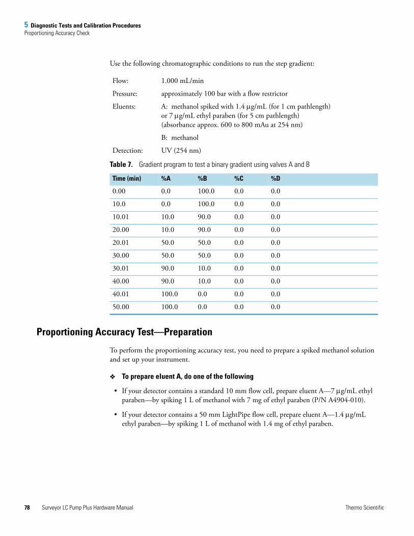
5 Diagnostic Tests and Calibration ProceduresProportioning Accuracy Check
78
Use the following chromatographic conditions to run the step gradient:
Proportioning Accuracy Test—Preparation
To perform the proportioning accuracy test, you need to prepare a spiked methanol solution and set up your instrument.
To prepare eluent A, do one of the following
• If your detector contains a standard 10 mm flow cell, prepare eluent A—7 μg/mL ethyl paraben—by spiking 1 L of methanol with 7 mg of ethyl paraben (P/N A4904-010).
• If your detector contains a 50 mm LightPipe flow cell, prepare eluent A—1.4 μg/mL ethyl paraben—by spiking 1 L of methanol with 1.4 mg of ethyl paraben.
Flow: 1.000 mL/min
Pressure: approximately 100 bar with a flow restrictor
Eluents: A: methanol spiked with 1.4 μg/mL (for 1 cm pathlength)or 7 μg/mL ethyl paraben (for 5 cm pathlength)(absorbance approx. 600 to 800 mAu at 254 nm)
B: methanol
Detection: UV (254 nm)
Table 7. Gradient program to test a binary gradient using valves A and B
Time (min) %A %B %C %D
0.00 0.0 100.0 0.0 0.0
10.0 0.0 100.0 0.0 0.0
10.01 10.0 90.0 0.0 0.0
20.00 10.0 90.0 0.0 0.0
20.01 50.0 50.0 0.0 0.0
30.00 50.0 50.0 0.0 0.0
30.01 90.0 10.0 0.0 0.0
40.00 90.0 10.0 0.0 0.0
40.01 100.0 0.0 0.0 0.0
50.00 100.0 0.0 0.0 0.0
Surveyor LC Pump Plus Hardware Manual Thermo Scientific
5 Diagnostic Tests and Calibration ProceduresProportioning Accuracy Check
T
To set up your instrument to test valves A and B
1. Fill solvent reservoir A with the solution prepared above.
2. Fill solvent reservoirs B, C, and D with methanol.
3. Purge all four solvent lines.
4. Replace the column with a flow restrictor (backpressure regulator).
5. Equilibrate the proportioning valves by pumping on all four channels (25% A, 25% B, 25% C, 25% D) at a flow rate of 1.0 mL/min for 20 minutes.
Testing Proportioning Accuracy
To test the proportioning accuracy of your Surveyor LC Pump Plus, prepare your instrument as instructed above.
To collect two data files containing pump gradient profiles
1. If you have not already done so, equilibrate the proportioning valves by pumping on all four channels (25% A, 25% B, 25% C, 25% D) at a flow rate of 1 mL/min for 20 minutes.
2. Create an acquisition method with the chromatographic conditions listed on page 78.
3. Place a vial that contains methanol in position A1 of the autosampler. Then make two injections of methanol using this method.
With the current set up, the autosampler injects methanol into the solvent stream at the beginning of the gradient program when the solvent is 100% methanol. Alternatively, you can remove the autosampler from your instrument configuration and trigger the run from the detector.
4. Analyze the results of the second injection as described in the following topic.
Note 100% of the spiked solution in the flow cell of your detector should produce an absorbance of approximately 600 to 800 mAU. If the absorbance at the 100% level is above 800 mAU, dilute the spiked solution with methanol.
hermo Scientific Surveyor LC Pump Plus Hardware Manual 79
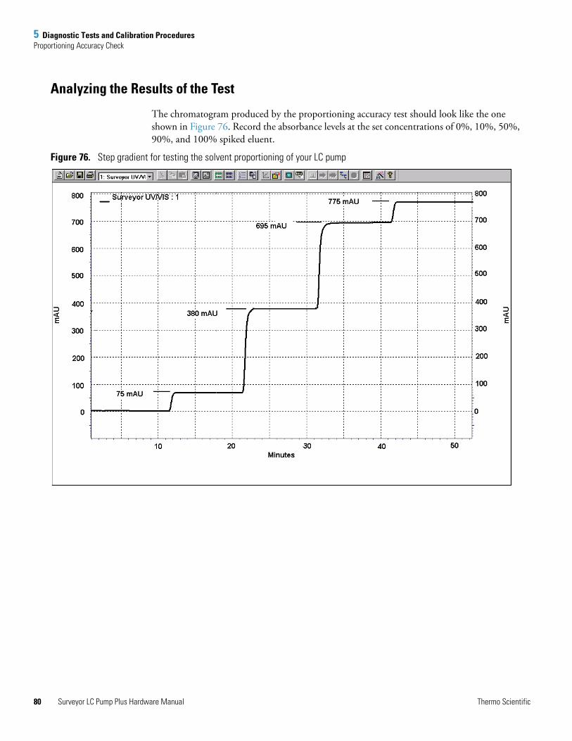
5 Diagnostic Tests and Calibration ProceduresProportioning Accuracy Check
80
Analyzing the Results of the Test
The chromatogram produced by the proportioning accuracy test should look like the one shown in Figure 76. Record the absorbance levels at the set concentrations of 0%, 10%, 50%, 90%, and 100% spiked eluent.
Figure 76. Step gradient for testing the solvent proportioning of your LC pump
Surveyor LC Pump Plus Hardware Manual Thermo Scientific
5 Diagnostic Tests and Calibration ProceduresProportioning Accuracy Check
T
The results for the 10%, 50%, and 90% steps of the step gradient are shown in Figure 76. As Figure 76 shows, the absorbance value for 100% spiked eluent is 775 mAU (775 mAU – 0 mAU). As Figure 76 shows, The absorbance values for the 10%, 50% and 90% steps are 75, 380, and 695 mAU, respectively.
The step heights as a percentage of the absorbance level at 100% spiked eluent are calculated as follows:
10% step = [(75 mAU – 0 mAU) / (775 mAu – 0 mAU)] × 100 = 9.7%
50% step = [(380 mAU – 0 mAU) / (775 mAu – 0 mAU)] × 100 = 49.0%
90% step = [(695 mAU – 0 mAU) / (775 mAu – 0 mAU)] × 100 = 89.7%
Step heights should be within ±1% of the theoretical values. Therefore, a deviation greater than ±7.75 mAU for any of the steps is a failing result. If the pump passes both the pulsation and proportioning tests, it is working properly.
If the pump fails the proportioning test, try to restore proper performance by running the pump for one hour with 100% isopropyl alcohol on all four channels. If cleaning the proportioning valves fails to restore proper pump performance, contact your local Thermo Fisher Scientific service representative.
Actual conc. of 10% =
(Absorbance level at set concentration of 10%)– (Absorbance level at set concentration of 0%)
× 100 =(Absorbance level at set concentration of 100%)– (Absorbance level at set concentration of 0%)
Actual conc. of 50% =
(Absorbance level at set concentration of 50%)– (Absorbance level at set concentration of 0%)
× 100 =(Absorbance level at set concentration of 100%)– (Absorbance level at set concentration of 0%)
Actual conc. of 90% =
(Absorbance level at set concentration of 90%)– (Absorbance level at set concentration of 0%)
× 100 =(Absorbance level at set concentration of 100%)– (Absorbance level at set concentration of 0%)
hermo Scientific Surveyor LC Pump Plus Hardware Manual 81
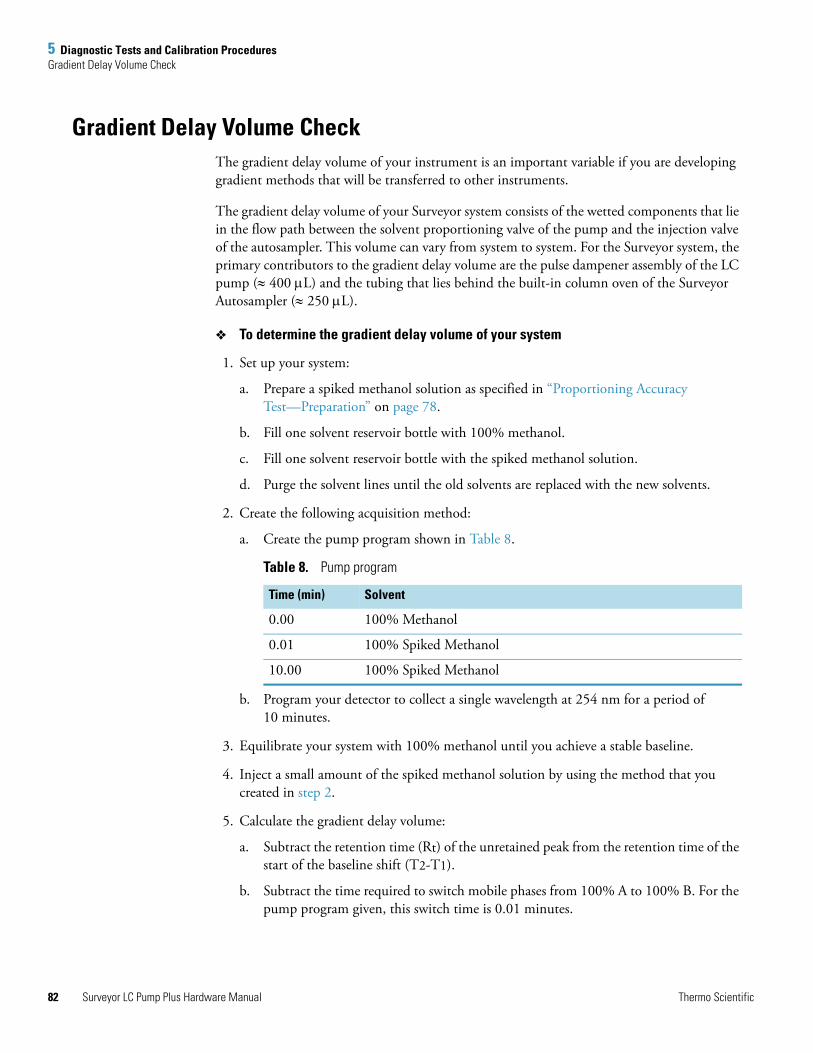
5 Diagnostic Tests and Calibration ProceduresGradient Delay Volume Check
82
Gradient Delay Volume CheckThe gradient delay volume of your instrument is an important variable if you are developing gradient methods that will be transferred to other instruments.
The gradient delay volume of your Surveyor system consists of the wetted components that lie in the flow path between the solvent proportioning valve of the pump and the injection valve of the autosampler. This volume can vary from system to system. For the Surveyor system, the primary contributors to the gradient delay volume are the pulse dampener assembly of the LC pump (≈ 400 μL) and the tubing that lies behind the built-in column oven of the Surveyor Autosampler (≈ 250 μL).
To determine the gradient delay volume of your system
1. Set up your system:
a. Prepare a spiked methanol solution as specified in “Proportioning Accuracy Test—Preparation” on page 78.
b. Fill one solvent reservoir bottle with 100% methanol.
c. Fill one solvent reservoir bottle with the spiked methanol solution.
d. Purge the solvent lines until the old solvents are replaced with the new solvents.
2. Create the following acquisition method:
a. Create the pump program shown in Table 8.
b. Program your detector to collect a single wavelength at 254 nm for a period of 10 minutes.
3. Equilibrate your system with 100% methanol until you achieve a stable baseline.
4. Inject a small amount of the spiked methanol solution by using the method that you created in step 2.
5. Calculate the gradient delay volume:
a. Subtract the retention time (Rt) of the unretained peak from the retention time of the start of the baseline shift (T2-T1).
b. Subtract the time required to switch mobile phases from 100% A to 100% B. For the pump program given, this switch time is 0.01 minutes.
Table 8. Pump program
Time (min) Solvent
0.00 100% Methanol
0.01 100% Spiked Methanol
10.00 100% Spiked Methanol
Surveyor LC Pump Plus Hardware Manual Thermo Scientific
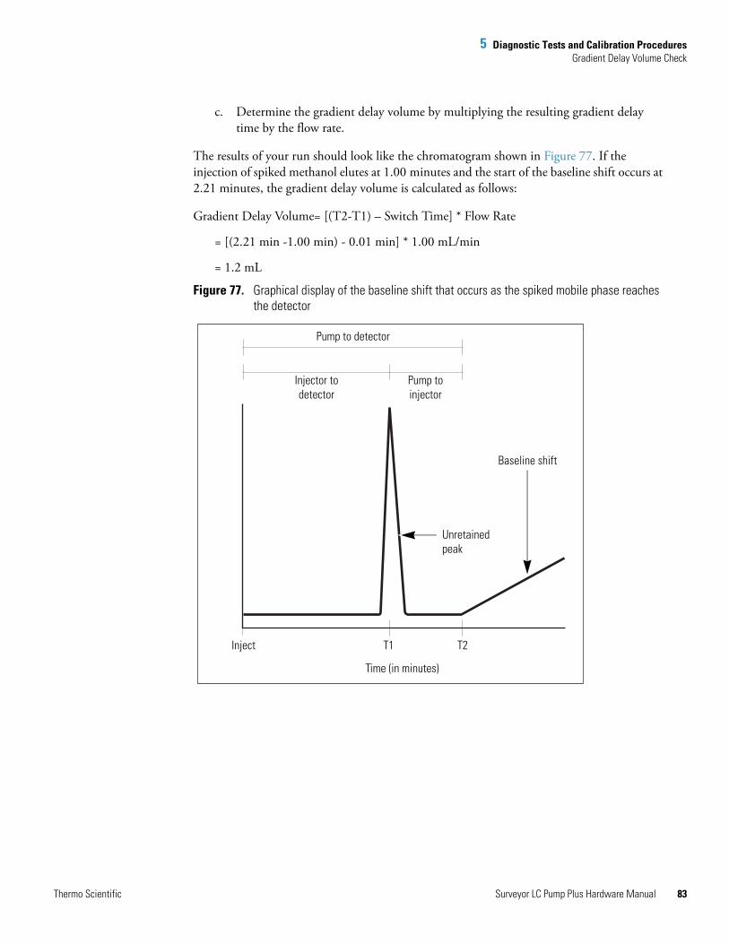
5 Diagnostic Tests and Calibration ProceduresGradient Delay Volume Check
T
c. Determine the gradient delay volume by multiplying the resulting gradient delay time by the flow rate.
The results of your run should look like the chromatogram shown in Figure 77. If the injection of spiked methanol elutes at 1.00 minutes and the start of the baseline shift occurs at 2.21 minutes, the gradient delay volume is calculated as follows:
Gradient Delay Volume= [(T2-T1) – Switch Time] * Flow Rate
= [(2.21 min -1.00 min) - 0.01 min] * 1.00 mL/min
= 1.2 mL
Figure 77. Graphical display of the baseline shift that occurs as the spiked mobile phase reaches the detector
Pump to detector
Injector to detector
Pump to injector
Unretained peak
Baseline shift
T2T1Inject
Time (in minutes)
hermo Scientific Surveyor LC Pump Plus Hardware Manual 83
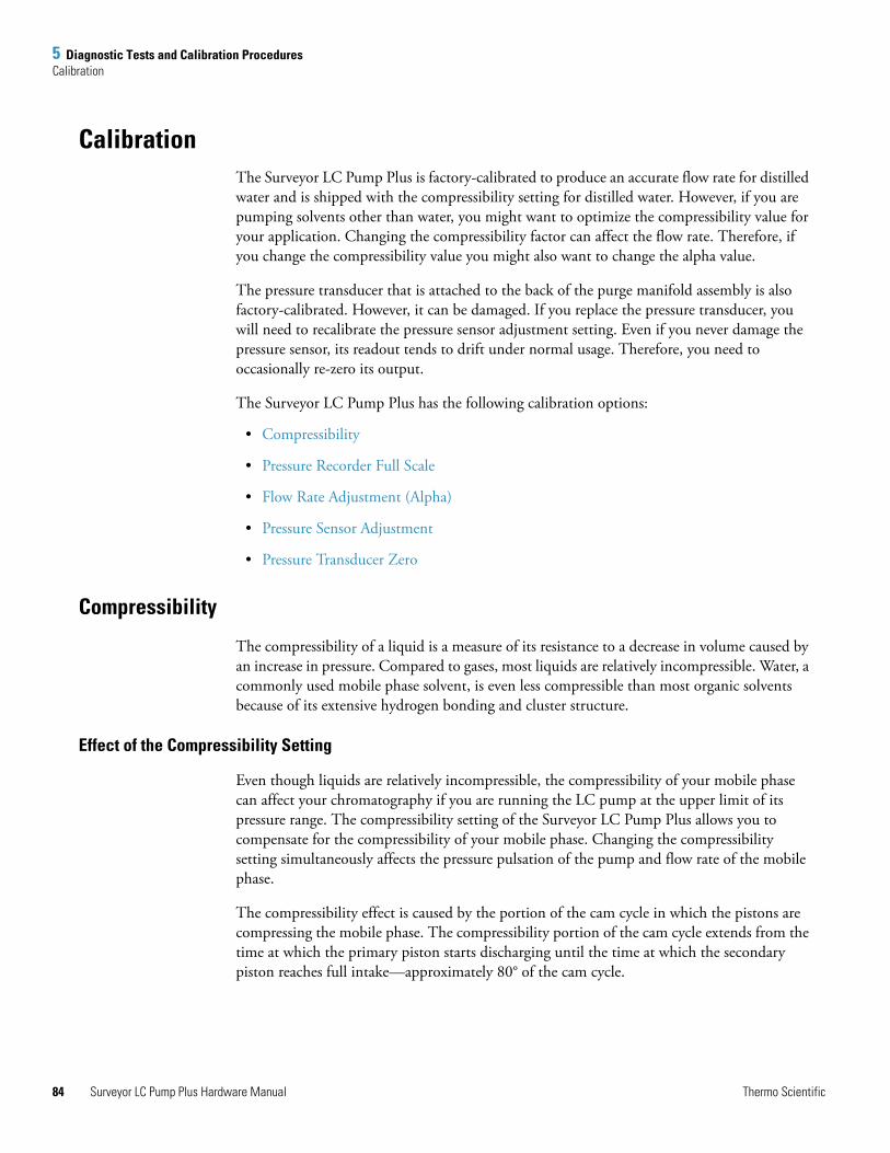
5 Diagnostic Tests and Calibration ProceduresCalibration
84
CalibrationThe Surveyor LC Pump Plus is factory-calibrated to produce an accurate flow rate for distilled water and is shipped with the compressibility setting for distilled water. However, if you are pumping solvents other than water, you might want to optimize the compressibility value for your application. Changing the compressibility factor can affect the flow rate. Therefore, if you change the compressibility value you might also want to change the alpha value.
The pressure transducer that is attached to the back of the purge manifold assembly is also factory-calibrated. However, it can be damaged. If you replace the pressure transducer, you will need to recalibrate the pressure sensor adjustment setting. Even if you never damage the pressure sensor, its readout tends to drift under normal usage. Therefore, you need to occasionally re-zero its output.
The Surveyor LC Pump Plus has the following calibration options:
• Compressibility
• Pressure Recorder Full Scale
• Flow Rate Adjustment (Alpha)
• Pressure Sensor Adjustment
• Pressure Transducer Zero
Compressibility
The compressibility of a liquid is a measure of its resistance to a decrease in volume caused by an increase in pressure. Compared to gases, most liquids are relatively incompressible. Water, a commonly used mobile phase solvent, is even less compressible than most organic solvents because of its extensive hydrogen bonding and cluster structure.
Effect of the Compressibility Setting
Even though liquids are relatively incompressible, the compressibility of your mobile phase can affect your chromatography if you are running the LC pump at the upper limit of its pressure range. The compressibility setting of the Surveyor LC Pump Plus allows you to compensate for the compressibility of your mobile phase. Changing the compressibility setting simultaneously affects the pressure pulsation of the pump and flow rate of the mobile phase.
The compressibility effect is caused by the portion of the cam cycle in which the pistons are compressing the mobile phase. The compressibility portion of the cam cycle extends from the time at which the primary piston starts discharging until the time at which the secondary piston reaches full intake—approximately 80° of the cam cycle.
Surveyor LC Pump Plus Hardware Manual Thermo Scientific
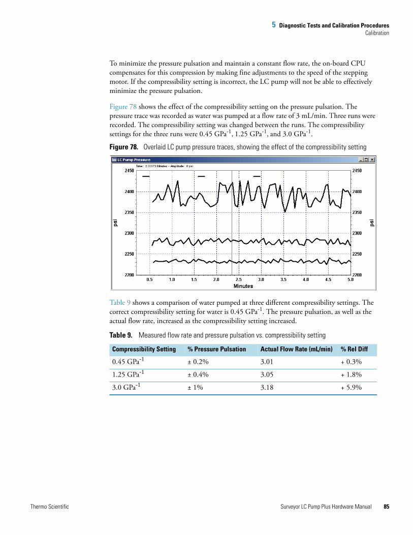
5 Diagnostic Tests and Calibration ProceduresCalibration
T
To minimize the pressure pulsation and maintain a constant flow rate, the on-board CPU compensates for this compression by making fine adjustments to the speed of the stepping motor. If the compressibility setting is incorrect, the LC pump will not be able to effectively minimize the pressure pulsation.
Figure 78 shows the effect of the compressibility setting on the pressure pulsation. The pressure trace was recorded as water was pumped at a flow rate of 3 mL/min. Three runs were recorded. The compressibility setting was changed between the runs. The compressibility settings for the three runs were 0.45 GPa-1, 1.25 GPa-1, and 3.0 GPa-1.
Figure 78. Overlaid LC pump pressure traces, showing the effect of the compressibility setting
Table 9 shows a comparison of water pumped at three different compressibility settings. The correct compressibility setting for water is 0.45 GPa-1. The pressure pulsation, as well as the actual flow rate, increased as the compressibility setting increased.
Table 9. Measured flow rate and pressure pulsation vs. compressibility setting
Compressibility Setting % Pressure Pulsation Actual Flow Rate (mL/min) % Rel Diff
0.45 GPa-1 ± 0.2% 3.01 + 0.3%
1.25 GPa-1 ± 0.4% 3.05 + 1.8%
3.0 GPa-1 ± 1% 3.18 + 5.9%
hermo Scientific Surveyor LC Pump Plus Hardware Manual 85
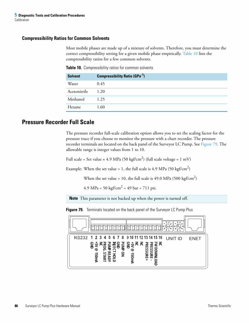
5 Diagnostic Tests and Calibration ProceduresCalibration
86
Compressibility Ratios for Common Solvents
Most mobile phases are made up of a mixture of solvents. Therefore, you must determine the correct compressibility setting for a given mobile phase empirically. Table 10 lists the compressibility ratios for a few common solvents.
Pressure Recorder Full Scale
The pressure recorder full-scale calibration option allows you to set the scaling factor for the pressure trace if you choose to monitor the pressure with a chart recorder. The pressure recorder terminals are located on the back panel of the Surveyor LC Pump. See Figure 79. The allowable range is integer values from 1 to 10.
Full scale = Set value × 4.9 MPa (50 kgf/cm2) (full scale voltage = 1 mV)
Example: When the set value = 1, the full scale is 4.9 MPa (50 kgf/cm2)
When the set value = 10, the full scale is 49.0 MPa (500 kgf/cm2)
4.9 MPa = 50 kgf/cm2 = 49 bar = 711 psi.
Figure 79. Terminals located on the back panel of the Surveyor LC Pump Plus
Table 10. Compressibility ratios for common solvents
Solvent Compressibility Ratio (GPa-1)
Water 0.45
Acetonitrile 1.20
Methanol 1.25
Hexane 1.60
Note This parameter is not backed up when the power is turned off.
UNIT ID ENETNCFW DOW
NLOAD
NC PRESSURE -PRESSURE+
+5V @ 15Om
AGNDPUMP ONGNDINJECT HOLDPUMP READYPROG. START
+5V @ 150m
AGND
NC NC
Surveyor LC Pump Plus Hardware Manual Thermo Scientific
5 Diagnostic Tests and Calibration ProceduresCalibration
T
Flow Rate Adjustment (Alpha)
The alpha value for your Surveyor LC Pump Plus is factory-calibrated based on a flow rate of 1.000 mL/min for distilled water. A sticker containing the factory calibration value is located inside the pump on the motor casing. You can optimize the alpha value for your application by updating the alpha setting. The allowable range for alpha values is 1 to 9.9. If you are pumping water, decreasing the alpha value by 1 decreases the flow rate by 1%, whereas increasing the alpha value by 1 increases the flow rate by 1%.
Pressure Sensor Adjustment
Reset this parameter when the pressure sensor is replaced. Each pressure sensor is labeled with a data sticker that contains a “0.XXXX” value for the pressure sensor adjustment setting. Multiply this value by 10,000 and then update the pressure sensor adjustment setting for your Surveyor LC Pump.
Pressure Transducer Zero
The pressure readout for the Surveyor LC Pump Plus is produced by a cell type potentiometer. This type of device tends to drift by small increments. Therefore, you will occasionally need to re-zero the readout. To update the pressure transducer zero value, turn off the pump flow and open the drain valve knob before clicking the pressure transducer zero button in the software program that operates your pump.
hermo Scientific Surveyor LC Pump Plus Hardware Manual 87

6
Troubleshooting
If it is properly maintained, the Surveyor LC Pump Plus will operate trouble-free for many years. Most pump problems can be avoided by simple, periodic maintenance, as described in Chapter 4, “Maintenance.” However, in the event that an error message is displayed or if a mechanical or electrical failure is suspected, the problem can be easily diagnosed. Further, if the diagnosis indicates that a problem exists with non user-serviceable parts inside the pump, a qualified Thermo Fisher Scientific service representative can replace most malfunctioning parts.
For more detailed chromatographic troubleshooting, see any HPLC troubleshooting reference book or call your local Thermo Fisher Scientific service representative.
Troubleshooting TipsBegin the diagnosis of the problem by performing the following steps.
Eliminate all other possible sources of trouble: Before you invest time trying to diagnose a suspected pump problem, you should verify that the pump is the only source of difficulty. Systematically eliminate all other instruments in your Surveyor HPLC system as the source of trouble. If you are not sure which component of your chromatography system is responsible for poor system performance, the General LC System Troubleshooting section found in this chapter contains many useful suggestions.
Contents
• Troubleshooting Tips
• General System Troubleshooting
• LC Pump Troubleshooting Guide
• Pump Pulsation
• Baseline Noise at Low Pressures (Under 40 Bar)
• Insufficient Solvent Flow from the Pump Outlet
• Irreproducible Retention Times
Thermo Scientific Surveyor LC Pump Plus Hardware Manual 89

6 TroubleshootingGeneral System Troubleshooting
90
When you are sure that it is the pump: Once you have isolated the pump as the only remaining source of difficulty, proceed to the troubleshooting tables for help in determining the exact cause of the problem.
General System TroubleshootingThis section contains general troubleshooting tips that will help in initial investigation of a problem with the Surveyor HPLC system.
No flow
1. Check mobile phase connections.
2. Check for leaks.
3. See item #3 on page 92.
High backpressure
1. Check the flow rate and the system/column specifications.
2. Check for tubing or column blockage.
3. See item #8 on page 93.
Unstable Baseline or Drift
1. System column not equilibrated; allow more equilibration time.
2. Refer to the troubleshooting guide in the hardware manual for your detector.
Baseline Noise
1. Check for air bubbles in the system.
2. Check for system solvent contamination.
No Peaks
1. Check the detector and the data system connections.
2. Refer to the troubleshooting guide in the hardware manual for your autosampler.
3. Check the chromatographic conditions.
Contaminating / Ghost Peaks
1. Clean system and column.
2. Refer to the troubleshooting guide in the hardware manual for your autosampler.
Surveyor LC Pump Plus Hardware Manual Thermo Scientific
6 TroubleshootingGeneral System Troubleshooting
T
Poor Peak Shape
1. Check system for leaks.
2. Check fittings and tubing lengths.
3. Check column performance.
4. Refer to the troubleshooting guide in the hardware manual for your autosampler.
5. Refer to the troubleshooting guide in the hardware manual for your detector.
Poor Retention Time Reproducibility
1. Check system for leaks and bubbles.
2. Allow more time to equilibrate the LC column.
3. Check column performance.
4. Refer to the troubleshooting guide in the hardware manual for your autosampler.
5. See item #6 on page 93.
Poor Peak Area Reproducibility
1. Check column performance.
2. Refer to the troubleshooting guide in the hardware manual for your autosampler.
No Instrument or Device Control
1. Check cable connections.
2. Check the system configuration.
3. Refer to the troubleshooting guide for the instrument in your LC system that is not communicating with the chromatography data system.
hermo Scientific Surveyor LC Pump Plus Hardware Manual 91
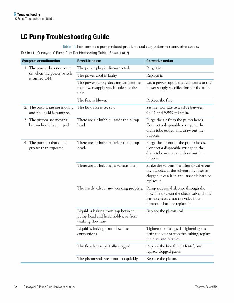
6 TroubleshootingLC Pump Troubleshooting Guide
92
LC Pump Troubleshooting GuideTable 11 lists common pump-related problems and suggestions for corrective action.
Table 11. Surveyor LC Pump Plus Troubleshooting Guide (Sheet 1 of 2)
Symptom or malfunction Possible cause Corrective action
1. The power does not come on when the power switch is turned ON.
The power plug is disconnected. Plug it in.
The power cord is faulty. Replace it.
The power supply does not conform to the power supply specification of the unit.
Use a power supply that conforms to the power supply specification for the unit.
The fuse is blown. Replace the fuse.
2. The pistons are not moving and no liquid is pumped.
The flow rate is set to 0. Set the flow rate to a value between 0.001 and 9.999 mL/min.
3. The pistons are moving, but no liquid is pumped.
There are air bubbles inside the pump head.
Purge the air from the pump heads. Connect a disposable syringe to the drain tube outlet, and draw out the bubbles.
4. The pump pulsation is greater than expected.
There are air bubbles inside the pump head.
Purge the air out of the pump heads. Connect a disposable syringe to the drain tube outlet, and draw out the bubbles.
There are air bubbles in solvent line. Shake the solvent line filter to drive out the bubbles. If the solvent line filter is clogged, clean it in an ultrasonic bath or replace it.
The check valve is not working properly. Pump isopropyl alcohol through the flow line to clean the check valve. If this has no effect, clean the valve in an ultrasonic bath or replace it.
Liquid is leaking from gap between pump head and head holder, or from washing flow line.
Replace the piston seal.
Liquid is leaking from flow line connections.
Tighten the fittings. If tightening the fittings does not stop the leaking, replace the nuts and ferrules.
The flow line is partially clogged. Replace the line filter. Identify and replace clogged parts.
The piston seals wear out too quickly. Replace the piston.
Surveyor LC Pump Plus Hardware Manual Thermo Scientific
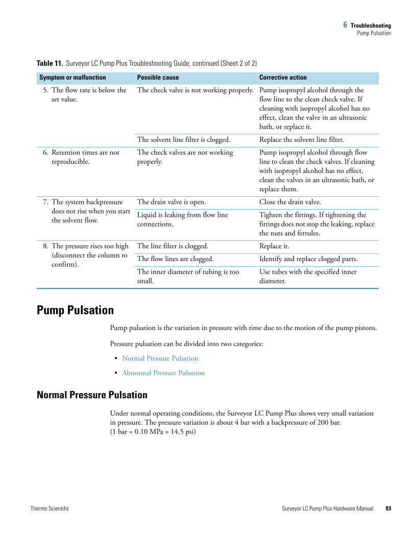
6 TroubleshootingPump Pulsation
T
Pump PulsationPump pulsation is the variation in pressure with time due to the motion of the pump pistons.
Pressure pulsation can be divided into two categories:
• Normal Pressure Pulsation
• Abnormal Pressure Pulsation
Normal Pressure Pulsation
Under normal operating conditions, the Surveyor LC Pump Plus shows very small variation in pressure. The pressure variation is about 4 bar with a backpressure of 200 bar.(1 bar = 0.10 MPa = 14.5 psi)
5. The flow rate is below the set value.
The check valve is not working properly. Pump isopropyl alcohol through the flow line to the clean check valve. If cleaning with isopropyl alcohol has no effect, clean the valve in an ultrasonic bath, or replace it.
The solvent line filter is clogged. Replace the solvent line filter.
6. Retention times are not reproducible.
The check valves are not working properly.
Pump isopropyl alcohol through flow line to clean the check valves. If cleaning with isopropyl alcohol has no effect, clean the valves in an ultrasonic bath, or replace them.
7. The system backpressure does not rise when you start the solvent flow.
The drain valve is open. Close the drain valve.
Liquid is leaking from flow line connections.
Tighten the fittings. If tightening the fittings does not stop the leaking, replace the nuts and ferrules.
8. The pressure rises too high (disconnect the column to confirm).
The line filter is clogged. Replace it.
The flow lines are clogged. Identify and replace clogged parts.
The inner diameter of tubing is too small.
Use tubes with the specified inner diameter.
Table 11. Surveyor LC Pump Plus Troubleshooting Guide, continued (Sheet 2 of 2)
Symptom or malfunction Possible cause Corrective action
hermo Scientific Surveyor LC Pump Plus Hardware Manual 93
6 TroubleshootingBaseline Noise at Low Pressures (Under 40 Bar)
94
Abnormal Pressure Pulsation
Abnormal pressure pulsations fall into two categories. Large pressure pulsations are generally considered to be those with a standard deviation in pressure of greater than 10 bar (145 psi). Minor pressure pulsations are those with a standard deviation in pressure of under 10 bar.
Pressure Pulsations with SD over 10 Bar
Pressure pulsations with a standard deviation of the pressure over 10 bar are, in most cases, caused by air bubbles trapped in one of the piston chambers. To clear trapped air bubbles, it is recommended that you run the LC pump at about 500 μL/min with methanol or acetonitrile for about 15 minutes.
Strong pump pulsations can also be caused by insufficient flow to the pump caused by a dirty solvent reservoir filter. To determine if the solvent reservoir filter is clogged, remove it from the solvent tubing and record the pressure trace when mobile phase is pumped. If the pressure pulsation returns to normal in the absence of the solvent reservoir filter, the filter is clogged. Replace the clogged filter and thoroughly purge the system.
If you determine that the cause is not related to trapped air, the cause might be related to one or more worn piston seals. Replace both piston seals as described in Chapter 4, “Maintenance.”
If the problem still persists after you change the piston seals, the problem is likely due to a contaminated check valve. Cleaning a check valve is normally not effective. Most likely, you will need to replace one or both check valve assemblies.
Pressure Pulsations with SD between 3 and 10 Bar
Pressure pulsations with a standard deviation of 3 to 10 bar are of various origins. You can continue working, but you should try to find the reason for the pulsation as soon as possible.
Baseline Noise at Low Pressures (Under 40 Bar)HPLC pumps are optimized to deliver a constant flow with a minimum of pressure fluctuations when they are operated in the range of 40 to 400 bar (580 to 5800 psi). The LC pump provides stable flow over the entire pressure range used by HPLC.
With backpressures under 40 bar, you might observe a slight instability in the detector baseline at high sensitivity.
This problem can usually be fixed by adding a flow restrictor to your system between the Surveyor LC Pump Plus and the autosampler to increase backpressure back to a level greater than 40 bar.
Capillary LC at 3 to 5 μL/min and 15 to 20 bar (for example, a 300 μm column at 3 μL/min) is a typical application susceptible to this problem.
Surveyor LC Pump Plus Hardware Manual Thermo Scientific
6 TroubleshootingInsufficient Solvent Flow from the Pump Outlet
T
Insufficient Solvent Flow from the Pump OutletIf there is insufficient flow when the LC pump is running, the problem is usually a result of one of the following:
• Pump Cavitation
• Blocked Proportioning Valve
• Blocked Check Valve
Pump Cavitation
A restricted flow from the solvent reservoir to the pump can cause the pump to cavitate, which results in erratic mobile phase delivery. In extreme cases, there might be no flow at all. The reason is usually either a blocked solvent reservoir filter or restricted solvent tubing. A possible, but much less probable, cause could be a restriction inside the vacuum degasser.
To determine the cause of the problem
1. Disconnect (at the inlet to the degasser) the tubing from solvent reservoir A and verify unrestricted flow of solvent.
2. If flow is normal, reconnect the tubing into the degasser and disconnect the corresponding degasser outlet tubing.
3. Once again, check for unrestricted flow. The flow out of the degasser will normally be slower than that going to the degasser.
4. Repeat the procedure for solvents B, C, and D.
Suspect a problem with the degasser only if there is virtually no flow coming out of the degasser.
Blocked Proportioning Valve
If flow from the degasser is nominal, check the proportioning valve. Measure the actual flow rate at a set rate of 1.000 mL/min with 100% of each solvent. If one or more of the values are low, clean the corresponding proportioning valve (for example, by pumping 100% isopropyl alcohol).
Blocked Check Valve
Insufficient flow rate can also be a result of a blockage in one or both check valves. In this case, replace the column with a flow restrictor and pump isopropyl alcohol through the solvent lines. If cleaning with isopropyl alcohol has no effect, remove the valve and clean it in an ultrasonic bath, or replace it.
hermo Scientific Surveyor LC Pump Plus Hardware Manual 95
6 TroubleshootingIrreproducible Retention Times
96
Irreproducible Retention Times There are many reasons for retention time problems. Some of the more common causes are listed below:
• An old or damaged column
• Unequilibrated column (Was a new column installed?)
• A validated method lacks robustness
• Changes in mobile phase composition
• Temperature fluctuations
• Pump problems
If you are using a pre-mixed mobile phase and you suspect the pump to be responsible, irreproducible retention times may be caused by a blocked check valve. If you are running a gradient or using the pump to mix your eluents, another cause of irreproducible retention times may be contaminated proportioning valves. Replace the column with a flow restrictor and run a step gradient as described in “Proportioning Accuracy Test—Preparation” on page 78.
Inaccuracy of the steps is most likely caused by contamination of the proportioning valves. Run the pump at least 2 hours with isopropyl alcohol before repeating the test.
Surveyor LC Pump Plus Hardware Manual Thermo Scientific
7
Accessories and Replaceable Parts
This chapter contains a list of parts and tools for maintaining the Surveyor LC Pump Plus and a list of parts that can be replaced by Thermo Fisher Scientific factory-trained personnel. To order parts, contact your local Thermo Fisher Scientific service representative. To facilitate the ordering process, part numbers are listed next to their respective parts.
Contents
• Surveyor LC Pump Accessory Kit
• Replacement Parts Required for Routine Maintenance
• Nonconsumable Replacement Parts
• Replacement Parts Required for Nonroutine Maintenance
• Solvent Interconnect Kit
• Other Parts and Assemblies
Thermo Scientific Surveyor LC Pump Plus Hardware Manual 97
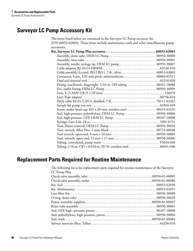
7 Accessories and Replaceable PartsSurveyor LC Pump Accessory Kit
98
Surveyor LC Pump Accessory KitThe items listed below are contained in the Surveyor LC Pump accessory kit (P/N 60053-62003). These items include maintenance tools and other miscellaneous pump accessories.Kit, Surveyor LC Pump Plus accessory . . . . . . . . . . . . . . . . . . . . . . . . . . . . . 60053-62003
Assembly, drain tube, OEM LC Pump . . . . . . . . . . . . . . . . . . . . . . . . . . . 00950-30008Assembly, rinse tube . . . . . . . . . . . . . . . . . . . . . . . . . . . . . . . . . . . . . . . . . 00950-30001Assembly, needle, syringe tip, OEM LC pump . . . . . . . . . . . . . . . . . . . . . 00950-30007Cable adaptor, RJ-45/14-D89FM. . . . . . . . . . . . . . . . . . . . . . . . . . . . . . . . . A3538-010Cable assembly, 6-cond, RJ11-RJ11, 7-ft., silver . . . . . . . . . . . . . . . . . . . . 60053-63003Connector, 8 pin, 3.81 mm pitch, minicombicon. . . . . . . . . . . . . . . . . . . 00004-02511Dual seal removal tool . . . . . . . . . . . . . . . . . . . . . . . . . . . . . . . . . . . . . . . . . A3216-020Fitting, nut/ferrule, fingertight, 1/16-in. OD tubing . . . . . . . . . . . . . . . . 00101-18088Frit, outlet fitting, OEM LC Pump . . . . . . . . . . . . . . . . . . . . . . . . . . . . . 00950-30009Fuse, 3.15 AMP S/B (5 × 20 mm) . . . . . . . . . . . . . . . . . . . . . . . . . . . . . . . . . . . 126078Luer-Type adaptor . . . . . . . . . . . . . . . . . . . . . . . . . . . . . . . . . . . . . . . . . . . . A0796-010Patch cable RJ-45, CAT-5, shielded, 7-ft. . . . . . . . . . . . . . . . . . . . . . . . . . 70111-63302Sample kit pump test mix . . . . . . . . . . . . . . . . . . . . . . . . . . . . . . . . . . . . . . . A4904-010Screw, socket head cap, M5 × 20 mm, stainless steel . . . . . . . . . . . . . . . . . 00419-63235Seal, high-pressure, polyethylene, OEM LC Pump . . . . . . . . . . . . . . . . . . 00950-30004Seal, high-pressure, GFP, OEM LC Pump . . . . . . . . . . . . . . . . . . . . . . . . 00107-18008Syringe, Luer-Lok, 10 cc. . . . . . . . . . . . . . . . . . . . . . . . . . . . . . . . . . . . . . . . 3301-0151Tool, Piston removal, OEM LC Pump . . . . . . . . . . . . . . . . . . . . . . . . . . . 00950-30010Tool, wrench, Allen Hex, 3 mm, black . . . . . . . . . . . . . . . . . . . . . . . . . . . 00725-00048Tool wrench, open-end, 8 mm × 10 mm . . . . . . . . . . . . . . . . . . . . . . . . . 00950-30005Tool, wrench, open-end, 13 mm × 17 mm . . . . . . . . . . . . . . . . . . . . . . . . 00950-30006Tubing, convoluted, pump waste . . . . . . . . . . . . . . . . . . . . . . . . . . . . . . . . . F5034-040Tubing 1/16-in. OD × 0.010-in. ID 9L stainless steel. . . . . . . . . . . . . . . . . . A0941-040
Replacement Parts Required for Routine MaintenanceThe following list is for replacement parts required for routine maintenance of the Surveyor LC Pump Plus.Check valve assembly, inlet . . . . . . . . . . . . . . . . . . . . . . . . . . . . . . . . . . . . .00950-01-00085Check valve assembly, outlet . . . . . . . . . . . . . . . . . . . . . . . . . . . . . . . . . . . .00950-01-00086Kit, Seal . . . . . . . . . . . . . . . . . . . . . . . . . . . . . . . . . . . . . . . . . . . . . . . . . . . . . 60053-62050Kit, Maintenance . . . . . . . . . . . . . . . . . . . . . . . . . . . . . . . . . . . . . . . . . . . . . . 60053-62051Line filter frit. . . . . . . . . . . . . . . . . . . . . . . . . . . . . . . . . . . . . . . . . . . . . . . . . . 00950-30009O-ring, drain valve . . . . . . . . . . . . . . . . . . . . . . . . . . . . . . . . . . . . . . . . . . . . . 00950-30029Piston assembly, sapphire. . . . . . . . . . . . . . . . . . . . . . . . . . . . . . . . . . . . . . .00950-01-00087Rinse tube assembly . . . . . . . . . . . . . . . . . . . . . . . . . . . . . . . . . . . . . . . . . . . . 00950-30001Seal, GFP, high- pressure, piston . . . . . . . . . . . . . . . . . . . . . . . . . . . . . . . . . . . 00107-18008Seal, polyethylene, high-pressure, piston . . . . . . . . . . . . . . . . . . . . . . . . . . . . . 00950-30004Seal, wash . . . . . . . . . . . . . . . . . . . . . . . . . . . . . . . . . . . . . . . . . . . . . . . . . .00950-01-00084Solvent reservoir filter, Teflon . . . . . . . . . . . . . . . . . . . . . . . . . . . . . . . . . . . . . . . A4258-010
Surveyor LC Pump Plus Hardware Manual Thermo Scientific
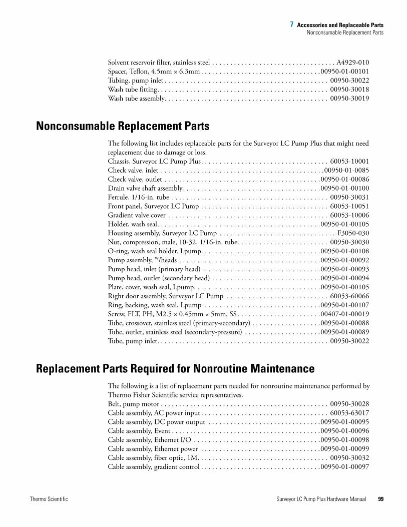
7 Accessories and Replaceable PartsNonconsumable Replacement Parts
Solvent reservoir filter, stainless steel . . . . . . . . . . . . . . . . . . . . . . . . . . . . . . . . . . A4929-010Spacer, Teflon, 4.5mm × 6.3mm . . . . . . . . . . . . . . . . . . . . . . . . . . . . . . . . .00950-01-00101Tubing, pump inlet . . . . . . . . . . . . . . . . . . . . . . . . . . . . . . . . . . . . . . . . . . . . . 00950-30022Wash tube fitting. . . . . . . . . . . . . . . . . . . . . . . . . . . . . . . . . . . . . . . . . . . . . . . 00950-30018Wash tube assembly. . . . . . . . . . . . . . . . . . . . . . . . . . . . . . . . . . . . . . . . . . . . . 00950-30019
Nonconsumable Replacement PartsThe following list includes replaceable parts for the Surveyor LC Pump Plus that might need replacement due to damage or loss.Chassis, Surveyor LC Pump Plus. . . . . . . . . . . . . . . . . . . . . . . . . . . . . . . . . . . 60053-10001Check valve, inlet . . . . . . . . . . . . . . . . . . . . . . . . . . . . . . . . . . . . . . . . . . . . .00950-01-0085Check valve, outlet . . . . . . . . . . . . . . . . . . . . . . . . . . . . . . . . . . . . . . . . . . .00950-01-00086Drain valve shaft assembly. . . . . . . . . . . . . . . . . . . . . . . . . . . . . . . . . . . . . .00950-01-00100Ferrule, 1/16-in. tube . . . . . . . . . . . . . . . . . . . . . . . . . . . . . . . . . . . . . . . . . . . 00950-30031Front panel, Surveyor LC Pump . . . . . . . . . . . . . . . . . . . . . . . . . . . . . . . . . . . 60053-10051Gradient valve cover . . . . . . . . . . . . . . . . . . . . . . . . . . . . . . . . . . . . . . . . . . . . 60053-10006Holder, wash seal. . . . . . . . . . . . . . . . . . . . . . . . . . . . . . . . . . . . . . . . . . . . .00950-01-00105Housing assembly, Surveyor LC Pump . . . . . . . . . . . . . . . . . . . . . . . . . . . . . . . . F3050-030Nut, compression, male, 10-32, 1/16-in. tube. . . . . . . . . . . . . . . . . . . . . . . . . 00950-30030O-ring, wash seal holder. Lpump. . . . . . . . . . . . . . . . . . . . . . . . . . . . . . . . .00950-01-00108Pump assembly, w/heads . . . . . . . . . . . . . . . . . . . . . . . . . . . . . . . . . . . . . . .00950-01-00092Pump head, inlet (primary head). . . . . . . . . . . . . . . . . . . . . . . . . . . . . . . . .00950-01-00093Pump head, outlet (secondary head) . . . . . . . . . . . . . . . . . . . . . . . . . . . . . .00950-01-00094Plate, cover, wash seal, Lpump. . . . . . . . . . . . . . . . . . . . . . . . . . . . . . . . . . .00950-01-00105Right door assembly, Surveyor LC Pump . . . . . . . . . . . . . . . . . . . . . . . . . . . . 60053-60066Ring, backing, wash seal, Lpump . . . . . . . . . . . . . . . . . . . . . . . . . . . . . . . .00950-01-00107Screw, FLT, PH, M2.5 × 0.45mm × 5mm, SS . . . . . . . . . . . . . . . . . . . . . . .00407-01-00019Tube, crossover, stainless steel (primary-secondary) . . . . . . . . . . . . . . . . . . .00950-01-00088Tube, outlet, stainless steel (secondary-pressure) . . . . . . . . . . . . . . . . . . . . .00950-01-00089Tube, pump inlet. . . . . . . . . . . . . . . . . . . . . . . . . . . . . . . . . . . . . . . . . . . . . . . 00950-30022
Replacement Parts Required for Nonroutine MaintenanceThe following is a list of replacement parts needed for nonroutine maintenance performed by Thermo Fisher Scientific service representatives.Belt, pump motor . . . . . . . . . . . . . . . . . . . . . . . . . . . . . . . . . . . . . . . . . . . . . . 00950-30028Cable assembly, AC power input . . . . . . . . . . . . . . . . . . . . . . . . . . . . . . . . . . . 60053-63017Cable assembly, DC power output . . . . . . . . . . . . . . . . . . . . . . . . . . . . . . .00950-01-00095Cable assembly, Event . . . . . . . . . . . . . . . . . . . . . . . . . . . . . . . . . . . . . . . . .00950-01-00096Cable assembly, Ethernet I/O . . . . . . . . . . . . . . . . . . . . . . . . . . . . . . . . . . .00950-01-00098Cable assembly, Ethernet power . . . . . . . . . . . . . . . . . . . . . . . . . . . . . . . . .00950-01-00099Cable assembly, fiber optic, 1M. . . . . . . . . . . . . . . . . . . . . . . . . . . . . . . . . . . . 00950-30032Cable assembly, gradient control . . . . . . . . . . . . . . . . . . . . . . . . . . . . . . . . .00950-01-00097
Thermo Scientific Surveyor LC Pump Plus Hardware Manual 99
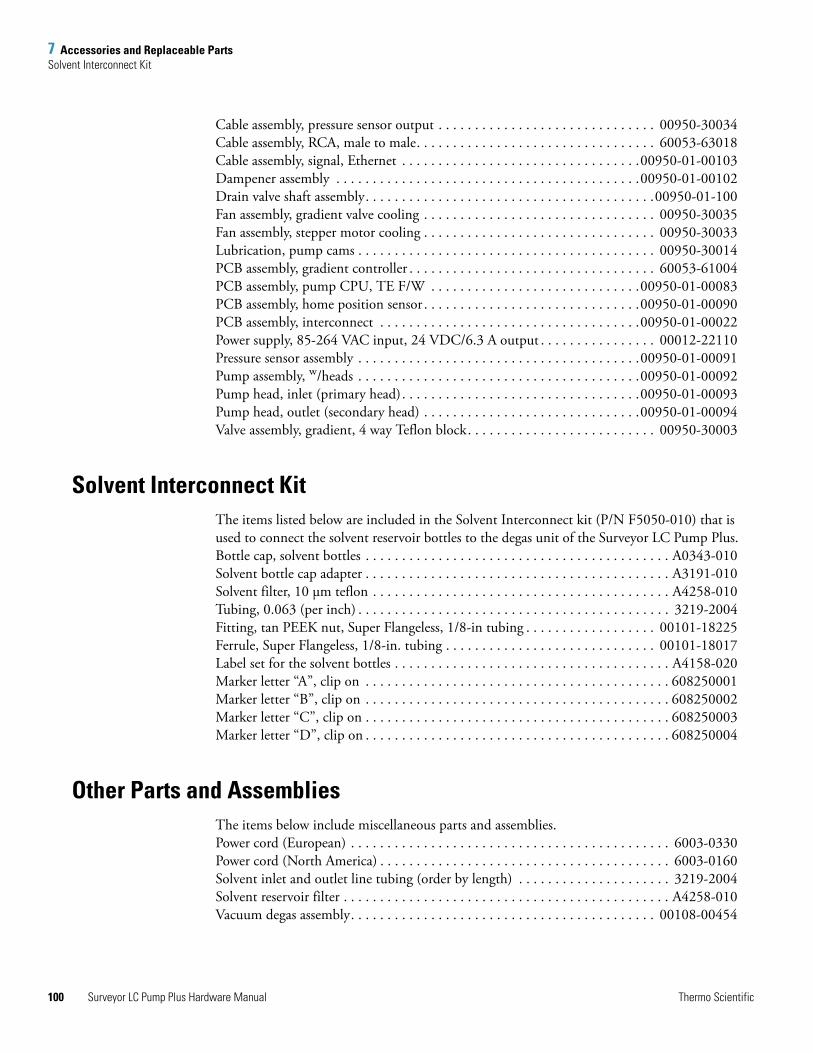
7 Accessories and Replaceable PartsSolvent Interconnect Kit
100
Cable assembly, pressure sensor output . . . . . . . . . . . . . . . . . . . . . . . . . . . . . . 00950-30034Cable assembly, RCA, male to male. . . . . . . . . . . . . . . . . . . . . . . . . . . . . . . . . 60053-63018Cable assembly, signal, Ethernet . . . . . . . . . . . . . . . . . . . . . . . . . . . . . . . . .00950-01-00103Dampener assembly . . . . . . . . . . . . . . . . . . . . . . . . . . . . . . . . . . . . . . . . . .00950-01-00102Drain valve shaft assembly. . . . . . . . . . . . . . . . . . . . . . . . . . . . . . . . . . . . . . . .00950-01-100Fan assembly, gradient valve cooling . . . . . . . . . . . . . . . . . . . . . . . . . . . . . . . . 00950-30035Fan assembly, stepper motor cooling . . . . . . . . . . . . . . . . . . . . . . . . . . . . . . . . 00950-30033Lubrication, pump cams . . . . . . . . . . . . . . . . . . . . . . . . . . . . . . . . . . . . . . . . . 00950-30014PCB assembly, gradient controller . . . . . . . . . . . . . . . . . . . . . . . . . . . . . . . . . . 60053-61004PCB assembly, pump CPU, TE F/W . . . . . . . . . . . . . . . . . . . . . . . . . . . . .00950-01-00083PCB assembly, home position sensor . . . . . . . . . . . . . . . . . . . . . . . . . . . . . .00950-01-00090PCB assembly, interconnect . . . . . . . . . . . . . . . . . . . . . . . . . . . . . . . . . . . .00950-01-00022Power supply, 85-264 VAC input, 24 VDC/6.3 A output . . . . . . . . . . . . . . . . 00012-22110Pressure sensor assembly . . . . . . . . . . . . . . . . . . . . . . . . . . . . . . . . . . . . . . .00950-01-00091Pump assembly, w/heads . . . . . . . . . . . . . . . . . . . . . . . . . . . . . . . . . . . . . . .00950-01-00092Pump head, inlet (primary head). . . . . . . . . . . . . . . . . . . . . . . . . . . . . . . . .00950-01-00093Pump head, outlet (secondary head) . . . . . . . . . . . . . . . . . . . . . . . . . . . . . .00950-01-00094Valve assembly, gradient, 4 way Teflon block. . . . . . . . . . . . . . . . . . . . . . . . . . 00950-30003
Solvent Interconnect KitThe items listed below are included in the Solvent Interconnect kit (P/N F5050-010) that is used to connect the solvent reservoir bottles to the degas unit of the Surveyor LC Pump Plus. Bottle cap, solvent bottles . . . . . . . . . . . . . . . . . . . . . . . . . . . . . . . . . . . . . . . . . . A0343-010Solvent bottle cap adapter . . . . . . . . . . . . . . . . . . . . . . . . . . . . . . . . . . . . . . . . . . A3191-010Solvent filter, 10 μm teflon . . . . . . . . . . . . . . . . . . . . . . . . . . . . . . . . . . . . . . . . . A4258-010Tubing, 0.063 (per inch) . . . . . . . . . . . . . . . . . . . . . . . . . . . . . . . . . . . . . . . . . . . 3219-2004Fitting, tan PEEK nut, Super Flangeless, 1/8-in tubing . . . . . . . . . . . . . . . . . . 00101-18225Ferrule, Super Flangeless, 1/8-in. tubing . . . . . . . . . . . . . . . . . . . . . . . . . . . . . 00101-18017Label set for the solvent bottles . . . . . . . . . . . . . . . . . . . . . . . . . . . . . . . . . . . . . . A4158-020Marker letter “A”, clip on . . . . . . . . . . . . . . . . . . . . . . . . . . . . . . . . . . . . . . . . . . 608250001Marker letter “B”, clip on . . . . . . . . . . . . . . . . . . . . . . . . . . . . . . . . . . . . . . . . . . 608250002Marker letter “C”, clip on . . . . . . . . . . . . . . . . . . . . . . . . . . . . . . . . . . . . . . . . . . 608250003Marker letter “D”, clip on . . . . . . . . . . . . . . . . . . . . . . . . . . . . . . . . . . . . . . . . . . 608250004
Other Parts and AssembliesThe items below include miscellaneous parts and assemblies.Power cord (European) . . . . . . . . . . . . . . . . . . . . . . . . . . . . . . . . . . . . . . . . . . . . 6003-0330Power cord (North America) . . . . . . . . . . . . . . . . . . . . . . . . . . . . . . . . . . . . . . . . 6003-0160Solvent inlet and outlet line tubing (order by length) . . . . . . . . . . . . . . . . . . . . . 3219-2004Solvent reservoir filter . . . . . . . . . . . . . . . . . . . . . . . . . . . . . . . . . . . . . . . . . . . . . A4258-010Vacuum degas assembly. . . . . . . . . . . . . . . . . . . . . . . . . . . . . . . . . . . . . . . . . . 00108-00454
Surveyor LC Pump Plus Hardware Manual Thermo Scientific
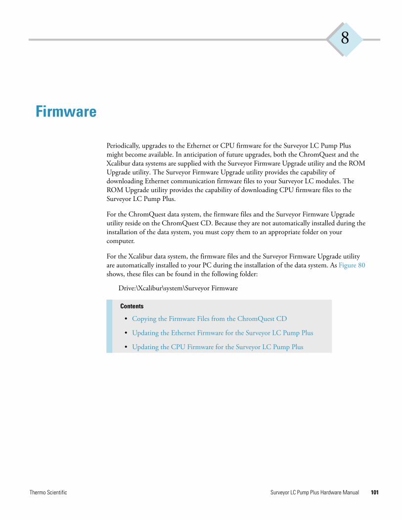
8
Firmware
Periodically, upgrades to the Ethernet or CPU firmware for the Surveyor LC Pump Plus might become available. In anticipation of future upgrades, both the ChromQuest and the Xcalibur data systems are supplied with the Surveyor Firmware Upgrade utility and the ROM Upgrade utility. The Surveyor Firmware Upgrade utility provides the capability of downloading Ethernet communication firmware files to your Surveyor LC modules. The ROM Upgrade utility provides the capability of downloading CPU firmware files to the Surveyor LC Pump Plus.
For the ChromQuest data system, the firmware files and the Surveyor Firmware Upgrade utility reside on the ChromQuest CD. Because they are not automatically installed during the installation of the data system, you must copy them to an appropriate folder on your computer.
For the Xcalibur data system, the firmware files and the Surveyor Firmware Upgrade utility are automatically installed to your PC during the installation of the data system. As Figure 80 shows, these files can be found in the following folder:
Drive:\Xcalibur\system\Surveyor Firmware
Contents
• Copying the Firmware Files from the ChromQuest CD
• Updating the Ethernet Firmware for the Surveyor LC Pump Plus
• Updating the CPU Firmware for the Surveyor LC Pump Plus
Thermo Scientific Surveyor LC Pump Plus Hardware Manual 101
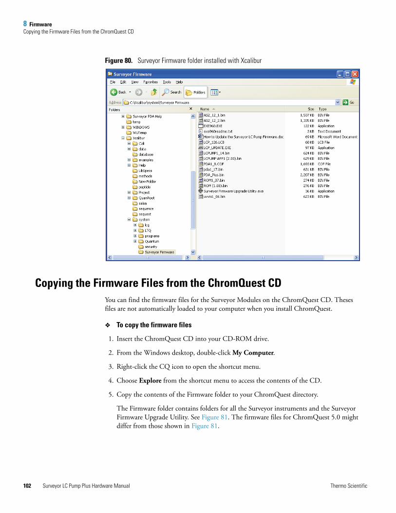
8 FirmwareCopying the Firmware Files from the ChromQuest CD
102
Figure 80. Surveyor Firmware folder installed with Xcalibur
Copying the Firmware Files from the ChromQuest CDYou can find the firmware files for the Surveyor Modules on the ChromQuest CD. Theses files are not automatically loaded to your computer when you install ChromQuest.
To copy the firmware files
1. Insert the ChromQuest CD into your CD-ROM drive.
2. From the Windows desktop, double-click My Computer.
3. Right-click the CQ icon to open the shortcut menu.
4. Choose Explore from the shortcut menu to access the contents of the CD.
5. Copy the contents of the Firmware folder to your ChromQuest directory.
The Firmware folder contains folders for all the Surveyor instruments and the Surveyor Firmware Upgrade Utility. See Figure 81. The firmware files for ChromQuest 5.0 might differ from those shown in Figure 81.
Surveyor LC Pump Plus Hardware Manual Thermo Scientific
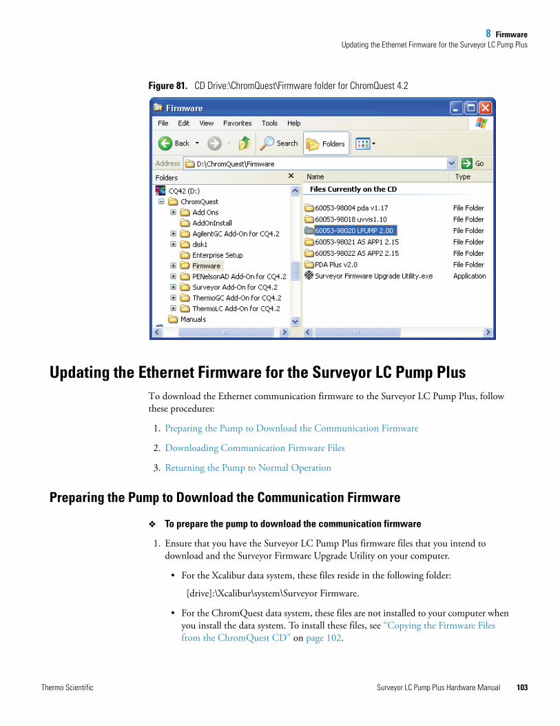
8 FirmwareUpdating the Ethernet Firmware for the Surveyor LC Pump Plus
Figure 81. CD Drive:\ChromQuest\Firmware folder for ChromQuest 4.2
Updating the Ethernet Firmware for the Surveyor LC Pump PlusTo download the Ethernet communication firmware to the Surveyor LC Pump Plus, follow these procedures:
1. Preparing the Pump to Download the Communication Firmware
2. Downloading Communication Firmware Files
3. Returning the Pump to Normal Operation
Preparing the Pump to Download the Communication Firmware
To prepare the pump to download the communication firmware
1. Ensure that you have the Surveyor LC Pump Plus firmware files that you intend to download and the Surveyor Firmware Upgrade Utility on your computer.
• For the Xcalibur data system, these files reside in the following folder:
[drive]:\Xcalibur\system\Surveyor Firmware.
• For the ChromQuest data system, these files are not installed to your computer when you install the data system. To install these files, see “Copying the Firmware Files from the ChromQuest CD” on page 102.
Thermo Scientific Surveyor LC Pump Plus Hardware Manual 103
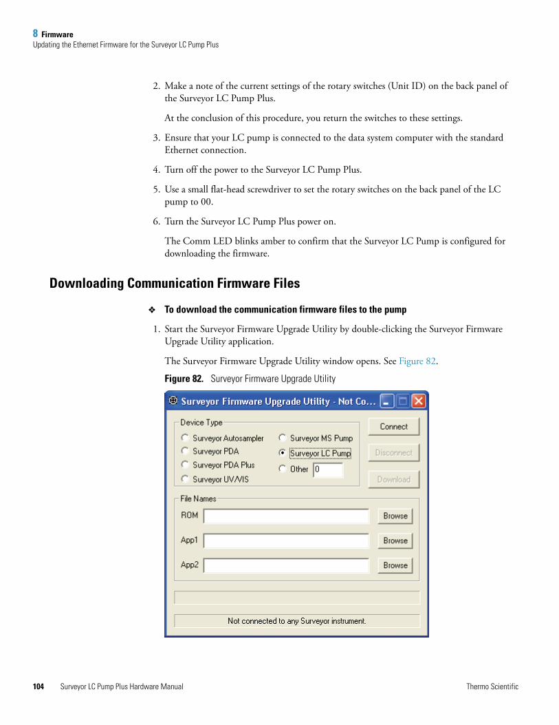
8 FirmwareUpdating the Ethernet Firmware for the Surveyor LC Pump Plus
104
2. Make a note of the current settings of the rotary switches (Unit ID) on the back panel of the Surveyor LC Pump Plus.
At the conclusion of this procedure, you return the switches to these settings.
3. Ensure that your LC pump is connected to the data system computer with the standard Ethernet connection.
4. Turn off the power to the Surveyor LC Pump Plus.
5. Use a small flat-head screwdriver to set the rotary switches on the back panel of the LC pump to 00.
6. Turn the Surveyor LC Pump Plus power on.
The Comm LED blinks amber to confirm that the Surveyor LC Pump is configured for downloading the firmware.
Downloading Communication Firmware Files
To download the communication firmware files to the pump
1. Start the Surveyor Firmware Upgrade Utility by double-clicking the Surveyor Firmware Upgrade Utility application.
The Surveyor Firmware Upgrade Utility window opens. See Figure 82.
Figure 82. Surveyor Firmware Upgrade Utility
Surveyor LC Pump Plus Hardware Manual Thermo Scientific
8 FirmwareUpdating the Ethernet Firmware for the Surveyor LC Pump Plus
2. In the Surveyor Firmware Upgrade Utility window, initiate the communication with the pump:
a. Under Device Type, select the Surveyor LC Pump option (see Figure 82).
b. Click Connect.
The status display at the bottom of the Surveyor Firmware Upgrade Utility window indicates that a connection has been made.
3. Select the appropriate firmware files (see Figure 83) for the Surveyor LC Pump Plus:
• Under File Names, click Browse to the right of the ROM box to select the ROM file (“ROM*.bin”).
The filename appears in the ROM box.
• Under File Names, click Browse to the right of the App1 box to select the APP1 file (“LC Pump*.bin”).
The filename appears in the App1 box.
CAUTION Do not interrupt the firmware download process. Do not turn off the power to the LC pump or close the Surveyor Firmware Upgrade Utility after you click Connect and establish communication. If you turn off the power to the LC pump or close the utility at this point, you will have to return the pump to the factory for reprogramming.
Note You must select both a ROM file and an APP1 file. Your Surveyor LC Pump will not work properly if the files are not downloaded together.
Thermo Scientific Surveyor LC Pump Plus Hardware Manual 105
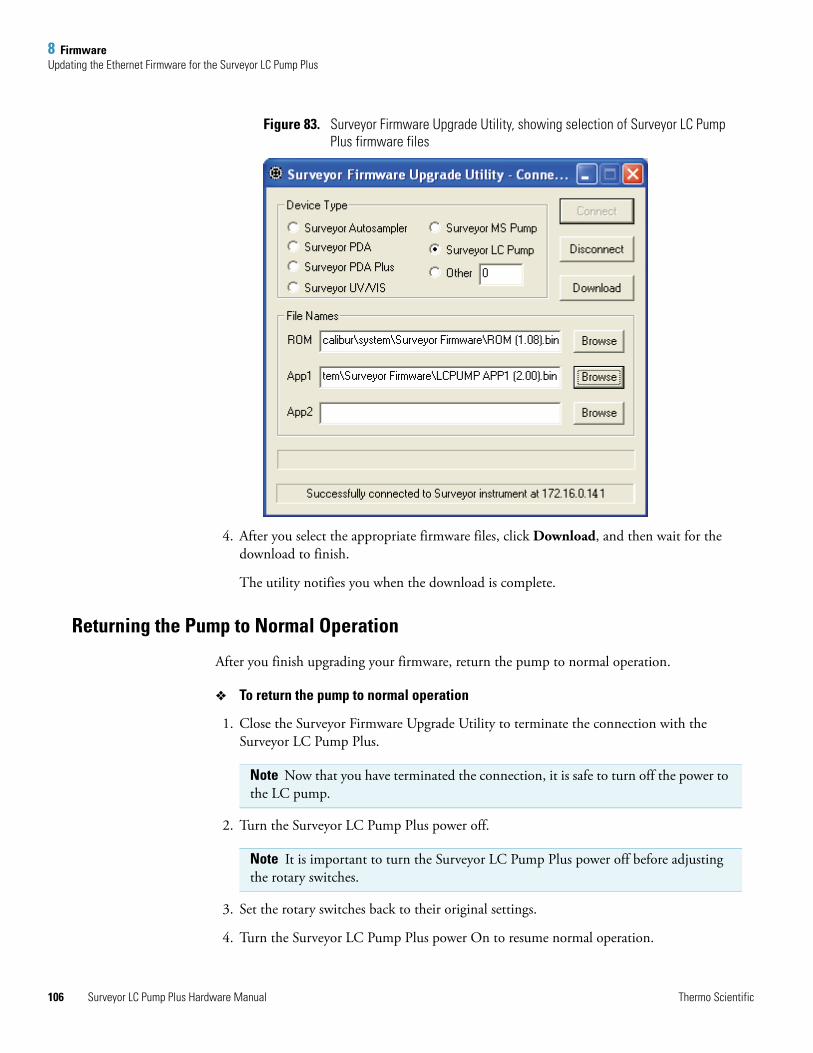
8 FirmwareUpdating the Ethernet Firmware for the Surveyor LC Pump Plus
106
Figure 83. Surveyor Firmware Upgrade Utility, showing selection of Surveyor LC Pump Plus firmware files
4. After you select the appropriate firmware files, click Download, and then wait for the download to finish.
The utility notifies you when the download is complete.
Returning the Pump to Normal Operation
After you finish upgrading your firmware, return the pump to normal operation.
To return the pump to normal operation
1. Close the Surveyor Firmware Upgrade Utility to terminate the connection with the Surveyor LC Pump Plus.
2. Turn the Surveyor LC Pump Plus power off.
3. Set the rotary switches back to their original settings.
4. Turn the Surveyor LC Pump Plus power On to resume normal operation.
Note Now that you have terminated the connection, it is safe to turn off the power to the LC pump.
Note It is important to turn the Surveyor LC Pump Plus power off before adjusting the rotary switches.
Surveyor LC Pump Plus Hardware Manual Thermo Scientific
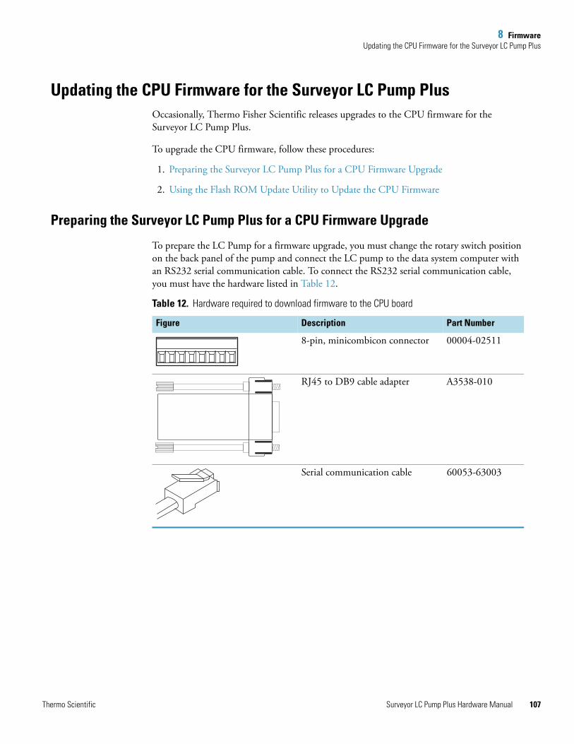
8 FirmwareUpdating the CPU Firmware for the Surveyor LC Pump Plus
Updating the CPU Firmware for the Surveyor LC Pump PlusOccasionally, Thermo Fisher Scientific releases upgrades to the CPU firmware for the Surveyor LC Pump Plus.
To upgrade the CPU firmware, follow these procedures:
1. Preparing the Surveyor LC Pump Plus for a CPU Firmware Upgrade
2. Using the Flash ROM Update Utility to Update the CPU Firmware
Preparing the Surveyor LC Pump Plus for a CPU Firmware Upgrade
To prepare the LC Pump for a firmware upgrade, you must change the rotary switch position on the back panel of the pump and connect the LC pump to the data system computer with an RS232 serial communication cable. To connect the RS232 serial communication cable, you must have the hardware listed in Table 12.
Table 12. Hardware required to download firmware to the CPU board
Figure Description Part Number
8-pin, minicombicon connector 00004-02511
RJ45 to DB9 cable adapter A3538-010
Serial communication cable 60053-63003
Thermo Scientific Surveyor LC Pump Plus Hardware Manual 107
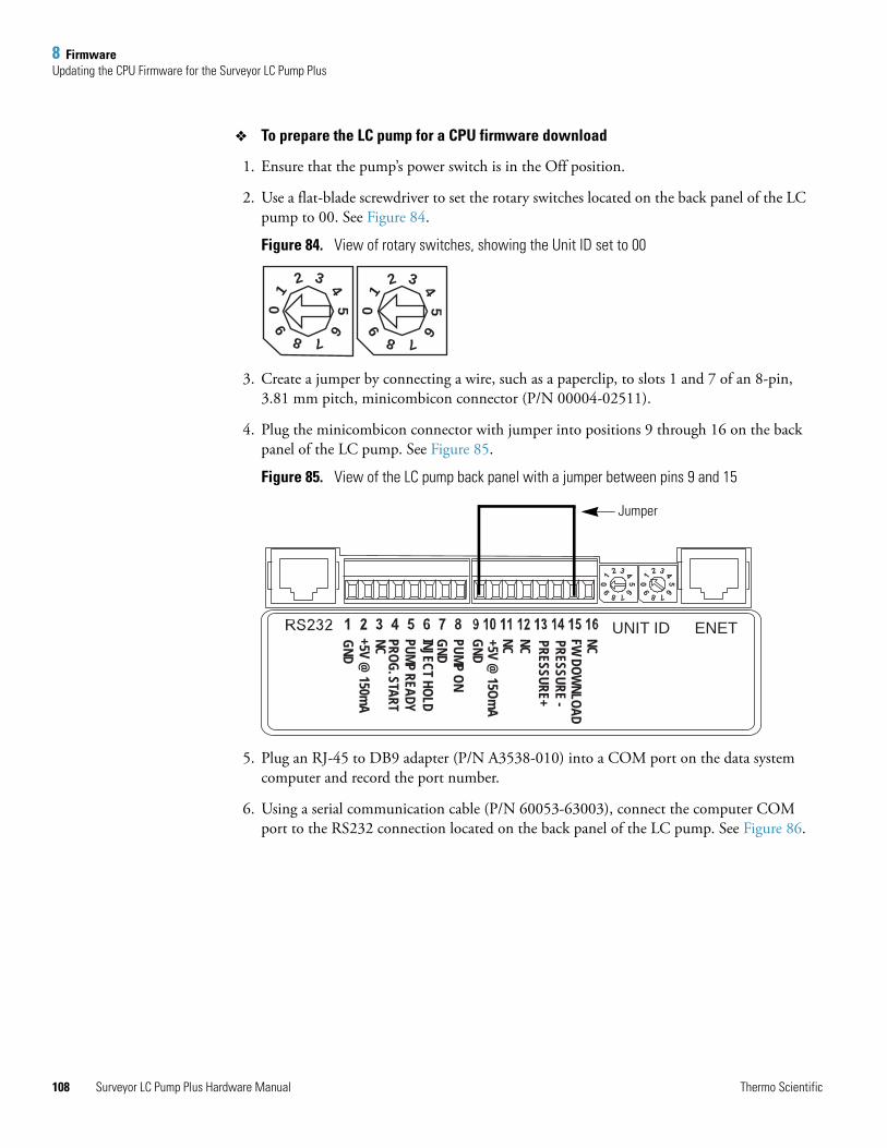
8 FirmwareUpdating the CPU Firmware for the Surveyor LC Pump Plus
108
To prepare the LC pump for a CPU firmware download
1. Ensure that the pump’s power switch is in the Off position.
2. Use a flat-blade screwdriver to set the rotary switches located on the back panel of the LC pump to 00. See Figure 84.
Figure 84. View of rotary switches, showing the Unit ID set to 00
3. Create a jumper by connecting a wire, such as a paperclip, to slots 1 and 7 of an 8-pin, 3.81 mm pitch, minicombicon connector (P/N 00004-02511).
4. Plug the minicombicon connector with jumper into positions 9 through 16 on the back panel of the LC pump. See Figure 85.
Figure 85. View of the LC pump back panel with a jumper between pins 9 and 15
5. Plug an RJ-45 to DB9 adapter (P/N A3538-010) into a COM port on the data system computer and record the port number.
6. Using a serial communication cable (P/N 60053-63003), connect the computer COM port to the RS232 connection located on the back panel of the LC pump. See Figure 86.
12 3 4
56
7890
1
2 3 45
6
7890
UNIT ID ENETNCFW DOW
NLOAD
NC PRESSURE -PRESSURE+
+5V @ 15Om
AGNDPUMP ONGNDINJECT HOLDPUMP READYPROG. START
+5V @ 150m
AGND
NC NC
Jumper
Surveyor LC Pump Plus Hardware Manual Thermo Scientific
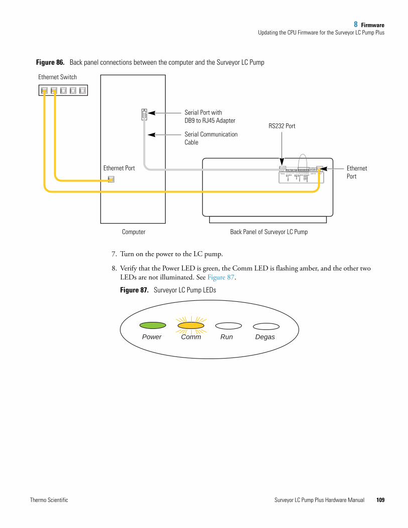
8 FirmwareUpdating the CPU Firmware for the Surveyor LC Pump Plus
Figure 86. Back panel connections between the computer and the Surveyor LC Pump
7. Turn on the power to the LC pump.
8. Verify that the Power LED is green, the Comm LED is flashing amber, and the other two LEDs are not illuminated. See Figure 87.
Figure 87. Surveyor LC Pump LEDs
UNIT IDNCFW DOW
NLOAD
NC PRESSURE -PRESSURE+
+5V @ 15Om
AGNDPUMP ONGND
+5V @ 150m
AGND
NC NC
RS232 ENET1 2 3 4 5 6 7 8 9 10 11 12 13 14 15 16
NC
Serial Port with DB9 to RJ45 Adapter
Serial Communication Cable
Ethernet Port
Ethernet Switch
RS232 Port
EthernetPort
Computer Back Panel of Surveyor LC Pump
Power Comm Run Degas
Thermo Scientific Surveyor LC Pump Plus Hardware Manual 109
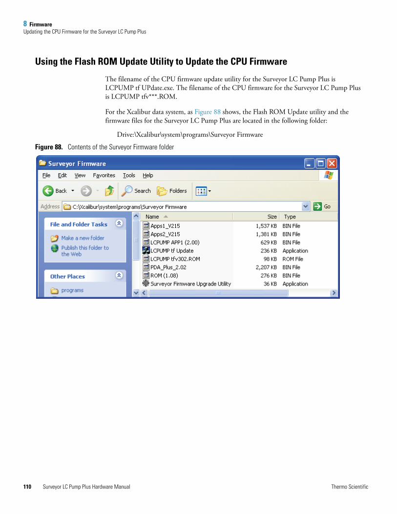
8 FirmwareUpdating the CPU Firmware for the Surveyor LC Pump Plus
110
Using the Flash ROM Update Utility to Update the CPU Firmware
The filename of the CPU firmware update utility for the Surveyor LC Pump Plus is LCPUMP tf UPdate.exe. The filename of the CPU firmware for the Surveyor LC Pump Plus is LCPUMP tfv***.ROM.
For the Xcalibur data system, as Figure 88 shows, the Flash ROM Update utility and the firmware files for the Surveyor LC Pump Plus are located in the following folder:
Drive:\Xcalibur\system\programs\Surveyor Firmware
Figure 88. Contents of the Surveyor Firmware folder
Surveyor LC Pump Plus Hardware Manual Thermo Scientific
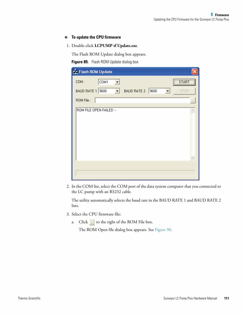
8 FirmwareUpdating the CPU Firmware for the Surveyor LC Pump Plus
To update the CPU firmware
1. Double-click LCPUMP tf Update.exe.
The Flash ROM Update dialog box appears.
Figure 89. Flash ROM Update dialog box
2. In the COM list, select the COM port of the data system computer that you connected to the LC pump with an RS232 cable.
The utility automatically selects the baud rate in the BAUD RATE 1 and BAUD RATE 2 lists.
3. Select the CPU firmware file:
a. Click to the right of the ROM File box.
The ROM Open file dialog box appears. See Figure 90.
Thermo Scientific Surveyor LC Pump Plus Hardware Manual 111
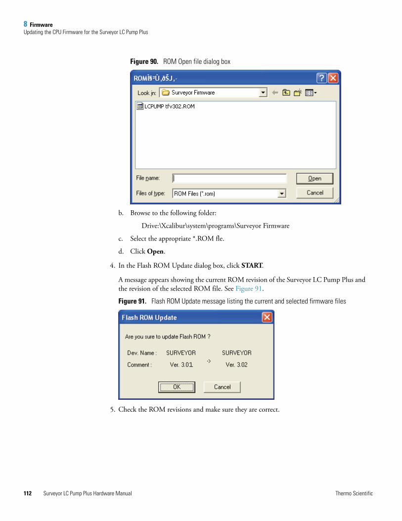
8 FirmwareUpdating the CPU Firmware for the Surveyor LC Pump Plus
112
Figure 90. ROM Open file dialog box
b. Browse to the following folder:
Drive:\Xcalibur\system\programs\Surveyor Firmware
c. Select the appropriate *.ROM fle.
d. Click Open.
4. In the Flash ROM Update dialog box, click START.
A message appears showing the current ROM revision of the Surveyor LC Pump Plus and the revision of the selected ROM file. See Figure 91.
Figure 91. Flash ROM Update message listing the current and selected firmware files
5. Check the ROM revisions and make sure they are correct.
Surveyor LC Pump Plus Hardware Manual Thermo Scientific
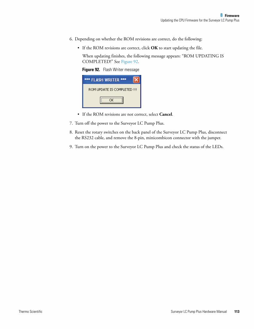
8 FirmwareUpdating the CPU Firmware for the Surveyor LC Pump Plus
6. Depending on whether the ROM revisions are correct, do the following:
• If the ROM revisions are correct, click OK to start updating the file.
When updating finishes, the following message appears: “ROM UPDATING IS COMPLETED!” See Figure 92.
Figure 92. Flash Writer message
• If the ROM revisions are not correct, select Cancel.
7. Turn off the power to the Surveyor LC Pump Plus.
8. Reset the rotary switches on the back panel of the Surveyor LC Pump Plus, disconnect the RS232 cable, and remove the 8-pin, minicombicon connector with the jumper.
9. Turn on the power to the Surveyor LC Pump Plus and check the status of the LEDs.
Thermo Scientific Surveyor LC Pump Plus Hardware Manual 113

I
Index
Aabrasion of pistons 61accessories
FEP tubing 21PEEK fittings 25stainless steel tubing 25
air bubbleseffect on pump pulsation 94effect on retention time reproducibility 91removing 94trapped in check valves 77
air in solvent line 38Allen hex wrench, purpose (figure) 54autosampler
configuring the signal polarities in ChromQuest 33configuring the signal polarity settings in Xcalibur 36connecting to pump 25
Bback panel connections for firmware downloads 109backpressure regulator See flow restrictorbaseline noise
caused by vacuum pump cycling 3troubleshooting 90
buffered mobile phasescause abrasion of the pistons 61rinse from pump after use 44
bushings, rinse tubing 44
Ccables
serial communication 108system synchronization 20
Capillary LC 94check valves
blocked 95cleaning 45, 77description 6effect of backpressure 6
removing 47schematic 7sonicating 49
ChromQuest CDfirmware files 102upgrade utilities 101
columnblockage 90not equilibrated 90, 91
Comm LED, description 11Comm LED, flashing amber 109communication problems 91compressibility
cam cycle 12defined 84of common solvents (table) 86
configuration in Xcalibur, pump 34connections
back panel 19solvent lines 21
converter board, updating firmware 103CPU firmware upgrades 107creep
See salt buildupcrossover tube
figure 4removing (figure) 47, 51
DDegas LED, description 11degasser
description 3specifications 15
delay volume, specification 15density of water 75detector, baseline instability 94Diagnostics button in ChromQuest 39disposable syringe, purpose 44drain valve knob 10
Thermo Scientific Surveyor LC Pump Plus Hardware Manual 115
116
Index: E
drain valve knob O-ringfigure 70replacing 70
drifting baseline 90dwell volume 82
Eeluents buffered, periodic rinsing 44erratic flow rates 38Ethernet cables (figure) 109Ethernet firmware downloads
cable connections 104rotary switch settings 104
ethyl paraben solution, preparation 78
Ffile types, bin 103filters
solvent reservoir 94firmware
CPU, updating with the Flash ROM Update utility 107Ethernet, upgrading with Surveyor Upgrade Utility 101
flow control 13flow rate
accuracy check 74maximum 15minimum 15
flow restrictor 94frit
line filter, replacing 64sinker, replacing 66
fusesfigure 72replacing 71
Gghost peaks 90gradient delay volume
determining 82pulse dampener 2pump 10
gradient program for testing proportioning accuracy 78
Hhead end of seal installer 55headless end of seal installer/remover tool 55hex socket head bolts, removing 54high backpressure 90
Iinstallation
checklist 18outlet tubing 25positioning the pump 19solvent lines 22system synchronization cable 20unpacking 18
Instrument Configuration dialog box (figure) 30instruments, configuring in ChromQuest 29isopropyl alcohol
cleaning piston 63cleaning the pump head 55
Jjumper used for shorting pins 9 and 15 on the back panel of the pump (figure) 108
LLC Pump accessory kit, part numbers 98LC Pump installation 18LEDs, front panel 10line filter body 9, 64line filter frit
figure 64replacing 64
low flow rate 38
MMain Menu window in ChromQuest, accessing 28maintenance
cleaning the check valves 46Maintenance Position button in ChromQuest 41Maintenance Position button in Xcalibur 43, 43performed by operator 38performed by Thermo Fisher Scientific service
representative 37replacing the drain valve O-ring 70replacing the fuses 71replacing the line filter frit 64replacing the piston seals 56replacing the solvent reservoir filter 66rinsing pistons 44schedule 38
Maintenance pagein ChromQuest 40in Xcalibur 42
minicombicon connector 108
Surveyor LC Pump Plus Hardware Manual Thermo Scientific
Index: N
Nno flow 90no peaks 90noisy baseline 90
Ooperating time
resetting in ChromQuest 41resetting in Xcalibur 43
Ppart numbers
for miscellaneous parts and assemblies 100list of parts in LC pump accessory kit 98solvent interconnect kit 100
peak area, reproducibility 91peak shape, effect of plumbing 91peak shape, poor 91photocoupler (figure) 13piston nut (figure) 62piston removal tool
used to remove piston 62used to remove wash seal holder 59
piston seals 5cause of wear 50figure 50replacing 55spring 50wear rate 50
pistons 5abrasion 61assembly (figure) 63cause of scratches 43salt buildup 43setting to maintenance position in Xcalibur 43setting to maintenance position, ChromQuest 41stroke volume 15
platform, solvent 23Power LED, description 11power requirements 15pressure
monitoring in ChromQuest 32operating range 15recorder terminals 86resolution 15settings range 15stability check 76
pressure transducerreplacing 87zeroing 87
pressure units 32proportioning accuracy test
calculations 81chromatogram 80described 77failure 81preparation of eluents 78
proportioning valvesblocked 95cleaning 81contamination 96description 3testing 77
pulse dampener, description 10pump
cavitation 95configuring in Xcalibur 34, 35gradient delay volume 10leaks 91, 91specifications 15
pump headsalignment during removal (figure) 54assembly (figure) 5
pump pulsationabnormal 94damaged piston seals 94defined 93dirty check valves 94dirty solvent reservoir filters 94normal 93
purge manifold assemblyopening for drain valve knob (figure) 70schematic 9
purging the solvent linesusing ChromQuest 67using Xcalibur 69
Rrear panel connections 19recording maintenance
ChromQuest 39Xcalibur 42
retention times, irreproducible 91, 96rinse tubing assembly 44rinsing behind the wash seals
figure 44to prevent salt buildup 44
rise in backpressure caused by inline filter 38Routine Maintenance Procedures (table) 38RS232 serial communication cable 107Run LED, description 11
Thermo Scientific Surveyor LC Pump Plus Hardware Manual 117

118
Index: S
Ssalt buildup
cause 43preventing 43
schedule, maintenance 38seal degradation, cause 50seal installer/remover tool (figure) 55seals
piston 5wash 6
sinker frit 66solvent lines
connecting 21purging 67reason to replace 69removing (figure) 47, 52
solvent platform 23solvent proportioning assembly, description 3solvent proportioning, described 12solvent reservoir filter
clogged 66figure 23replacement part 100replacing 66, 94
solvent tubing, replacement part 100solvents
erratic flow 95filtering 21no flow 95preventing bacterial growth 21saturation with air 21
specifications, pump 15Stack ID 32status LEDs 10, 109steel compression ring 23step-gradient for testing proportioning accuracy 77Surveyor dialog box (figure) 31Surveyor Firmware Upgrade Utility 103Surveyor LC Pump Configuration dialog box (figure) 32system synchronization cable
description 20installation 20
TTeflon spacer (figure) 56tools and parts
for replacing a piston 61for replacing a piston seal 50for replacing a wash seal 58
total flow, accuracy check 74
trapped air, removing 77troubleshooting
ghost peaks 90high backpressure 90no flow 90no instrument control 91no peaks 90poor peak shape 91retention time reproducibility 91unstable baseline 90
troubleshooting guide, pump 92tubing
1/16-in. high-pressure 4connecting pump to autosampler 64degasser 3washing line 8
UUnit ID set to 00 (figure) 108units for pressure read-out in ChromQuest 32unpacking your pump 18unstable baseline or drift 90
Vvacuum degasser
description 3specifications 15tubing 21
valvescheck
See check valvesproportioning
See proportioning valves
Wwash seals 6
replacing 58rinsing behind 44
wash tubing openings in the wash seal holder 59water, effect of temperature on density 75
XXcalibur
configuring the pump 34Maintenance page 41
Surveyor LC Pump Plus Hardware Manual Thermo Scientific