Embed Size (px)
Citation preview
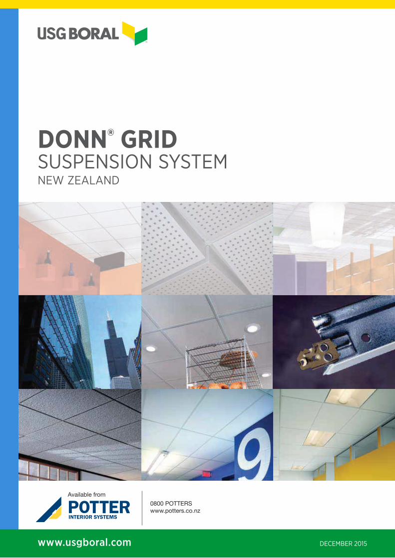
DONN® GRIDSUSPENSION SYSTEMNEW ZEALAND
DECEMBER 2015www.usgboral.com
Available from
0800 POTTERSwww.potters.co.nz
2 1 DECEMBER 2015 | DONN GRID MANUAL NZ
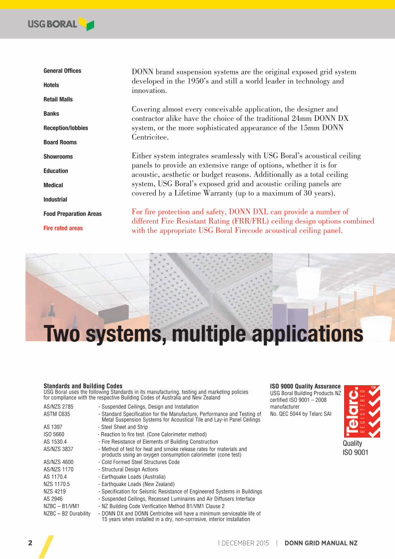
DONN brand suspension systems are the original exposed grid systemdeveloped in the 1950’s and still a world leader in technology andinnovation.
Covering almost every conceivable application, the designer and contractor alike have the choice of the traditional 24mm DONN DX system, or the more sophisticated appearance of the 15mm DONN Centricitee.
Either system integrates seamlessly with USG Boral’s acoustical ceiling panels to provide an extensive range of options, whether it is for acoustic, aesthetic or budget reasons. Additionally as a total ceiling system, USG Boral’s exposed grid and acoustic ceiling panels arecovered by a Lifetime Warranty (up to a maximum of 30 years).
For fire protection and safety, DONN DXL can provide a number of different Fire Resistant Rating (FRR/FRL) ceiling design options combined with the appropriate USG Boral Firecode acoustical ceiling panel.
General Offices
Hotels
Retail Malls
Banks
Reception/lobbies
Board Rooms
Showrooms
Education
Medical
Industrial
Food Preparation Areas
Fire rated areas
Standards and Building CodesUSG Boral uses the following Standards in its manufacturing, testing and marketing policies for compliance with the respective Building Codes of Australia and New Zealand
AS/NZS 2785 - Suspended Ceilings, Design and InstallationASTM C635 - Standard Specification for the Manufacture, Performance and Testing of
Metal Suspension Systems for Acoustical Tile and Lay-in Panel CeilingsAS 1397 - Steel Sheet and StripISO 5660 - Reaction to fire test. (Cone Calorimeter method)AS 1530.4 - Fire Resistance of Elements of Building ConstructionAS/NZS 3837 - Method of test for heat and smoke release rates for materials and
products using an oxygen consumption calorimeter (cone test)AS/NZS 4600 - Cold Formed Steel Structures CodeAS/NZS 1170 - Structural Design ActionsAS 1170.4 - Earthquake Loads (Australia)NZS 1170.5 - Earthquake Loads (New Zealand)NZS 4219 - Specification for Seismic Resistance of Engineered Systems in BuildingsAS 2946 - Suspended Ceilings, Recessed Luminaires and Air Diffusers InterfaceNZBC – B1/VM1 - NZ Building Code Verification Method B1/VM1 Clause 2NZBC – B2 Durability - DONN DX and DONN Centricitee will have a minimum serviceable life of
15 years when installed in a dry, non-corrosive, interior installation
ISO 9000 Quality AssuranceUSG Boral Building Products NZcertified ISO 9001 – 2008 manufacturer No. QEC 5044 by Telarc SAI
Two systems, multiple applications
Quality ISO 9001
3DONN GRID MANUAL NZ | 1 DECEMBER 2015
USER’S GUIDE
3
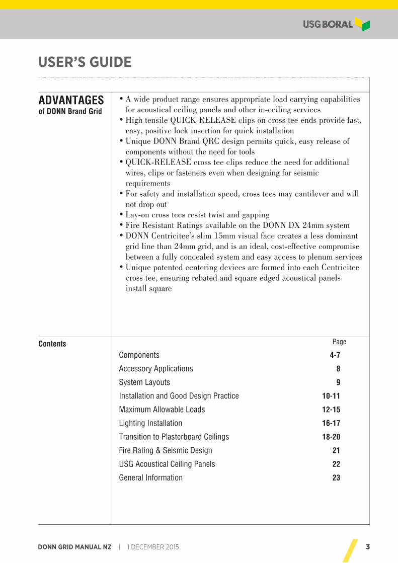
User’s Guide
seitilibapac gniyrrac daol etairporppa serusne egnar tcudorp ediw A •for acoustical ceiling panels and other in-ceiling services
,tsaf edivorp sdne eet ssorc no spilc ESAELER-KCIUQ elisnet hgiH •easy, positive lock insertion for quick installation
fo esaeler ysae ,kciuq stimrep ngised CRQ dnarB NNOD euqinU •components without the need for tools
lanoitidda rof deen eht ecuder spilc eet ssorc ESAELER-KCIUQ •wires, clips or fasteners even when designing for seismic requirements
lliw dna revelitnac yam seet ssorc ,deeps noitallatsni dna ytefas roF •not drop out
gnippag dna tsiwt tsiser seet ssorc no-yaL •metsys mm42 XD NNOD eht no elbaliava sgnitaR tnatsiseR eriF •
tnanimod ssel a setaerc ecaf lausiv mm51 mils s’eeticirtneC NNOD •grid line than 24mm grid, and is an ideal, cost-effective compromise between a fully concealed system and easy access to plenum services
eeticirtneC hcae otni demrof era secived gniretnec detnetap euqinU •cross tee, ensuring rebated and square edged acoustical panels install square
ADVANTAGESof DONN Brand Grid
Page
Components 4-7
Accessory Applications 8
System Layouts 9
Installation and Good Design Practice 10-11
Maximum Allowable Loads 12-15
Lighting Installation 16-17
Transition to Plasterboard Ceilings 18-20
Fire Rating & Seismic Design 21
USG Acoustical Ceiling Panels 22
General Information 23
Contents
© 2015
4 1 DECEMBER 2015 | DONN GRID MANUAL NZ
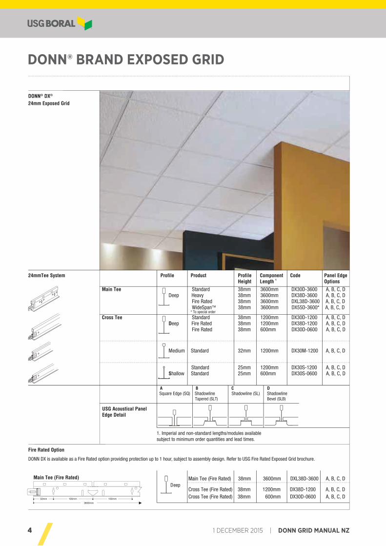
DONN® BRAND EXPOSED GRID
© 20154
24mmTee System Profile Product Profile Component Code Panel Edge Height Length 1 Options
Main Tee Standard 38mm 3600mm DX30D-3600 A, B, C, D Deep Heavy 38mm 3600mm DX38D-3600 A, B, C, D
Fire Rated 38mm 3600mm DXL38D-3600 A, B, C, D WideSpanTM 38mm 3600mm DX55D-3600* A, B, C, D
* To special order
Cross Tee Standard 38mm 1200mm DX30D-1200 A, B, C, D Deep Fire Rated 38mm 1200mm DX38D-1200 A, B, C, D
Fire Rated 38mm 600mm DX30D-0600 A, B, C, D
Medium Standard 32mm 1200mm DX30M-1200 A, B, C, D
Standard 25mm 1200mm DX30S-1200 A, B, C, D Shallow Standard 25mm 600mm DX30S-0600 A, B, C, D
DONN® DX®
24mm Exposed Grid
Fire Rated Option
DONN DX is available as a Fire Rated option providing protection up to 1 hour, subject to assembly design. Refer to USG Fire Rated Exposed Grid brochure.
USG Acoustical Panel Edge Detail
A B C DSquare Edge (SQ) Shadowline Shadowline (SL) Shadowline Tapered (SLT) Bevel (SLB)
Main Tee (Fire Rated) 38mm 3600mm DXL38D-3600 A, B, C, D
Cross Tee (Fire Rated) 38mm 1200mm DX38D-1200 A, B, C, DCross Tee (Fire Rated) 38mm 600mm DX30D-0600 A, B, C, D
Main Tee (Fire Rated)
mm001 mm001 mm05
3600mm
DONN® BrandExposed Grid
System Components
Deep
1. Imperial and non-standard lengths/modules available subject to minimum order quantities and lead times.
5DONN GRID MANUAL NZ | 1 DECEMBER 2015
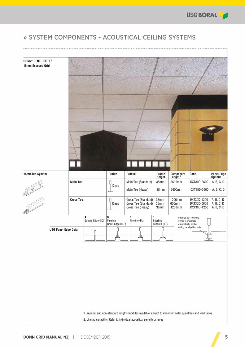
» SYSTEM COMPONENTS - ACOUSTICAL CEILING SYSTEMS
© 2015
Acoustical Ceiling Systems
5
DONN® CENTRICITEE®
15mm Exposed Grid
15mmTee System Profile Product Profile Component Code Panel Edge Height Length 1 Options
Main Tee Main Tee (Standard) 38mm 3600mm DXT30D-3600 A, B, C, D Deep
Main Tee (Heavy) 38mm 3600mm DXT38D-3600 A, B, C, D
Cross Tee Cross Tee (Standard) 38mm 1200mm DXT30D-1200 A, B, C, D D Cross Tee (Standard) 38mm 600mm DXT30D-0600 A, B, C, D
Cross Tee (Heavy) 38mm 1200mm DXT38D-1200 A, B, C, D
USG Panel Edge Detail
A B C DSquare Edge (SQ) 2 Fineline Fineline (FL) Interline Bevel Edge (FLB) Tapered (ILT)
Patented self centeringdevice in cross tees automatically centres ceiling panel grid module
DONN®
BrandExposed Grid
System Components
1. Imperial and non-standard lengths/modules available subject to minimum order quantities and lead times.
2. Limited suitability. Refer to individual acoustical panel brochures
eep
6 1 DECEMBER 2015 | DONN GRID MANUAL NZ
© 20156
Wall AnglesSystem ComponentsConstruction Details
1.8mm
22m
m
19mm
1.8mm
Standard
1.8mm19mm
40m
m
1.8mm
Long Leg
1.8mm
Shadowline Long Leg
19mm10mm
10m
m27
mm
1.8mm
Centricitee
1.8m
m
14mm
22m
m
1.8mm
Shadowline Shadow Edge
SeismicStandard
Crimping Option Field Cutting Option
Shadowline
Seismic Wall Channel
42m
m
26mm
1.8m
m
22mm
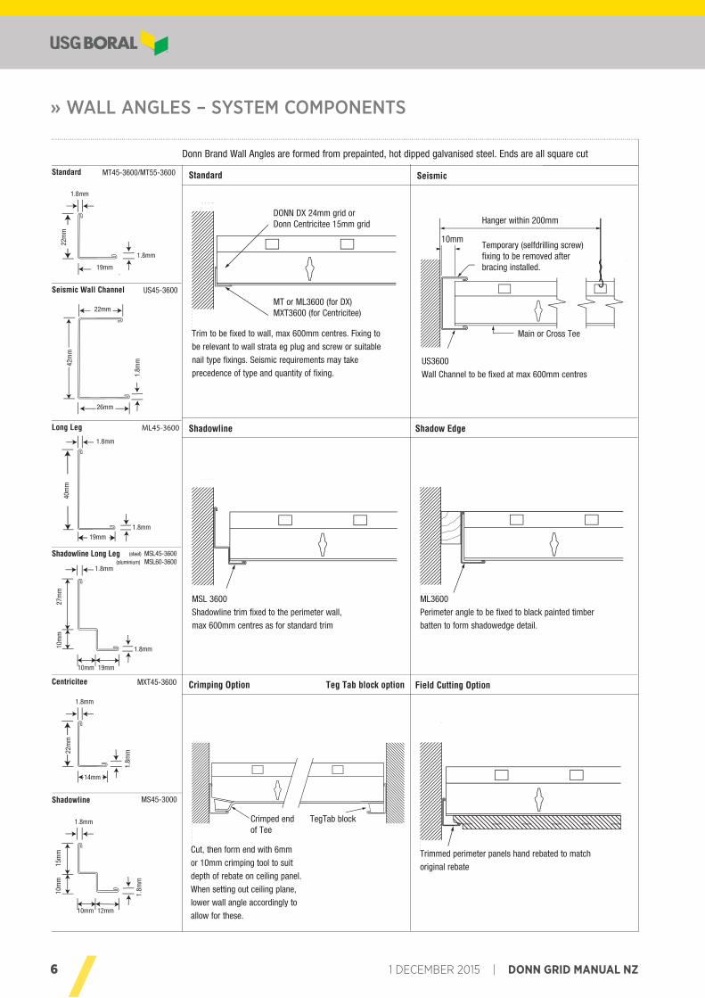
Cut, then form end with 6mm
or 10mm crimping tool to suit
depth of rebate on ceiling panel.
When setting out ceiling plane,
lower wall angle accordingly to
allow for these.
Trim to be fixed to wall, max 600mm centres. Fixing to
be relevant to wall strata eg plug and screw or suitable
nail type fixings. Seismic requirements may take
precedence of type and quantity of fixing.
Teg Tab block option
Donn Brand Wall Angles are formed from prepainted, hot dipped galvanised steel. Ends are all square cut
MT45-3600/MT55-3600
ML45-3600
MXT45-3600
MS45-3000
US45-3600
(steel) MSL45-3600(aluminium) MSL60-3600
Trimmed perimeter panels hand rebated to match
original rebate
MSL 3600
Shadowline trim fixed to the perimeter wall,
max 600mm centres as for standard trim
ML3600
Perimeter angle to be fixed to black painted timber
batten to form shadowedge detail.
US3600
Wall Channel to be fixed at max 600mm centres
1.8m
m
10mm 12mm
10m
m15
mm
1.8mm
DONN DX 24mm grid orDonn Centricitee 15mm grid
MT or ML3600 (for DX)MXT3600 (for Centricitee)
Hanger within 200mm
10mmTemporary (selfdrilling screw)fixing to be removed after bracing installed.
Main or Cross Tee
Crimped endof Tee
TegTab block
» WALL ANGLES – SYSTEM COMPONENTS
7DONN GRID MANUAL NZ | 1 DECEMBER 2015
» ACCESSORIES – SYSTEM COMPONENTS
© 2015 7
AccessoriesSystem Components
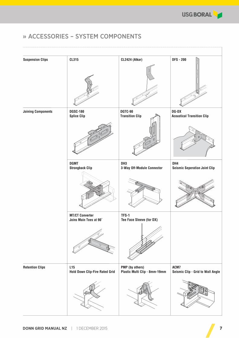
Suspension Clips
Joining Components
Retention Clips
DGSC-180Splice Clip
DGTC-90Transition Clip
DG-DXAcoustical Transition Clip
DGMTStrongback Clip
DH33-Way Off-Module Connector
DH4Seismic Seperation Joint Clip
MT/CT ConverterJoins Main Tees at 90˚
WSC18 (for SQ edge panels)Revoe Partition Attachment Clip
WSC38 (for rebated 24mm)WSC38-9 (for rebated 15mm)
L15Hold Down Clip-Fire Rated Grid
PMP (by others)Plastic Multi Clip - 8mm-19mm
ACM7Seismic Clip - Grid to Wall Angle
CL315 CL2424 (Atkar) DFS - 200
TFS-1Tee Face Sleeve (for DX)
8 1 DECEMBER 2015 | DONN GRID MANUAL NZ
ACCESSORY APPLICATIONS – CONSTRUCTION DETAILS
© 20158
Accessory ApplicationsConstruction Details
US3600channelmolding
tee
main tee
cross tee
wall angle
transition clip
main tee or cross tee
main tee or cross tee
transition clipteewall angle molding
main tee
cut
Bend down tabsover top of bulband flx
Splice Clip (A)
Bend down tabsover top of bulband flx
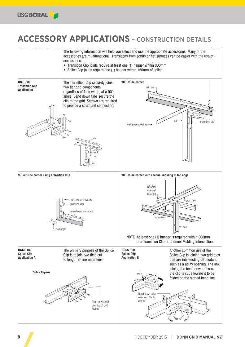
DGTC-90˚Transition ClipApplication
90˚ outside corner using Transition Clip
90˚ inside corner
90˚ inside corner with channel molding at top edge
DGSC-180Splice ClipApplication A
DGSC-180Splice ClipApplication B
The primary purpose of the SpliceClip is to join two field cutto length in-line main tees.
The Transition Clip securely joinstwo tier grid components,regardless of face width, at a 90˚ angle. Bend down tabs secure the clip to the grid. Screws are required to provide a structural connection.
NOTE: At least one (1) hanger is required within 300mm of a Transition Clip or Channel Molding intersection.
Another common use of the Splice Clip is joining two grid tees that are intersecting off module, such as a utility opening. The link joining the bend down tabs on the clip is cut allowing it to be folded on the slotted bend line.
The following information will help you select and use the appropriate accessories. Many of the accessories are multifunctional. Transitions from soffits or flat surfaces can be easier with the use of accessories.• Transition Clip joints require at least one (1) hanger within 300mm.• Splice Clip joints require one (1) hanger within 150mm of splice.
9DONN GRID MANUAL NZ | 1 DECEMBER 2015
SYSTEM LAYOUTS – CONSTRUCTION DETAILS
© 2015 9
5
43
2
1
6
3
2
1
64
3
2
1
2
1
5
7
4
System LayoutsConstruction Details
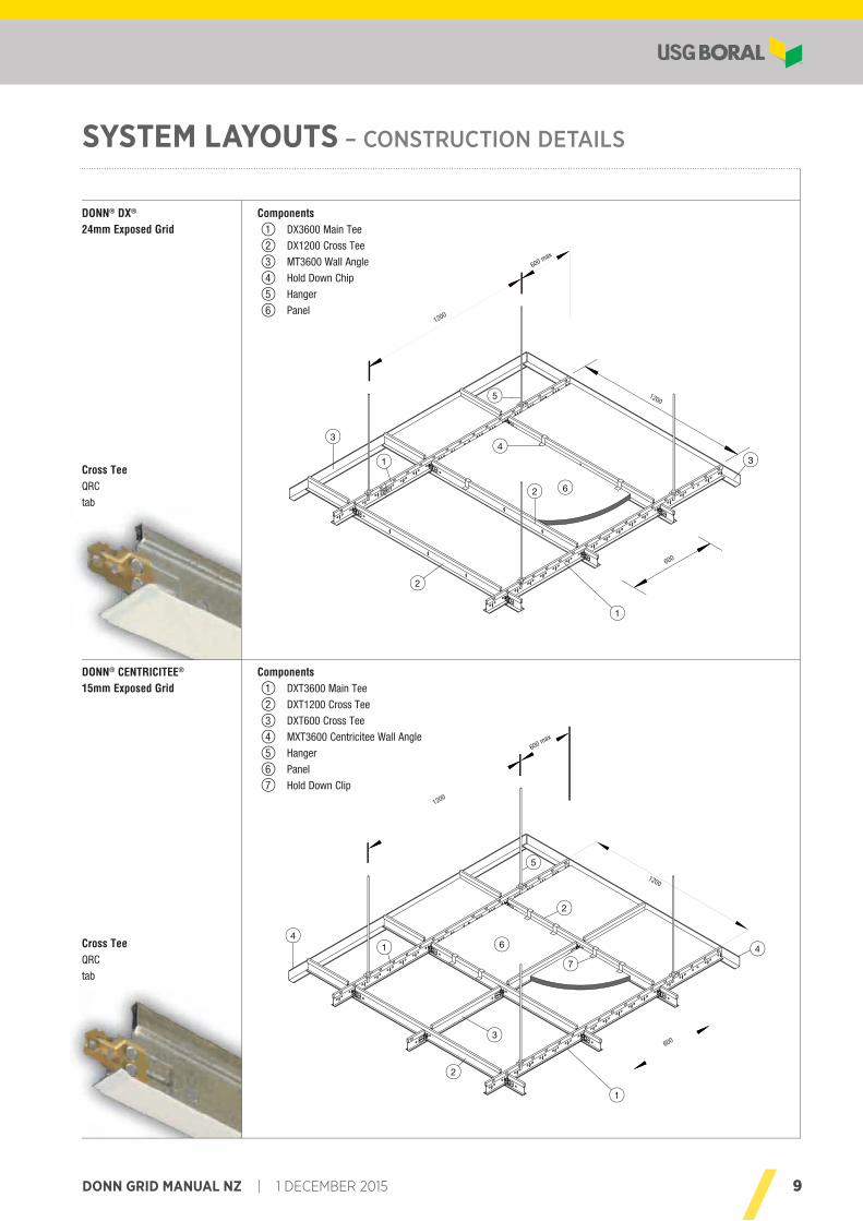
DONN® DX®
24mm Exposed GridComponents
1 DX3600 Main Tee
2 DX1200 Cross Tee
3 MT3600 Wall Angle
4 Hold Down Chip
5 Hanger
6 Panel
Components1 DXT3600 Main Tee
2 DXT1200 Cross Tee
3 DXT600 Cross Tee
4 MXT3600 Centricitee Wall Angle
5 Hanger
6 Panel
7 Hold Down Clip
DONN® CENTRICITEE®
15mm Exposed Grid
Cross TeeQRC
tab
Cross TeeQRC
tab
1200
600 max
1200
600
1200
600 max
1200
600
10 1 DECEMBER 2015 | DONN GRID MANUAL NZ
INSTALLATION – REQUIREMENTS & GOOD DESIGN PRACTICES
© 201510
Installation
Delivery, Storage and Handling
Installation
Seismic Bracing Requirements
Main Tee
Cross Tee
Suspension
- All materials shall be delivered in their original, unopened packages and stored for as short a time as possible, in an enclosed shelter providing protection from exposure to the elements and damage by/to other trades. Damaged, deteriorated or obviously faulty material is not to be installed and shall be removed from the premises.
- Materials should be handled in such a manner as to prevent racking distortion or physical damage.
- Ceiling layout should be planned prior to installation to determine grid configuration, direction etc. and to ensure that all fixing points are compatible with structural members and/or other services.
- Installation of exposed grid shall not begin until the building is closed in, fully glazed, roof watertight and residual
moisture from wet trades such as plaster, concrete and terrazzo has dissipated.
- Mechanical and electrical ductwork above the suspension system shall be completed before installation of the suspension
system.
Consult the USG Boral Seismic Design Guide.
- For standard installations Main Tees are spaced at 1200mm centres.
- Where heavy ceiling panels are used, close Main Tees in to 600mm centres. Refer Loadings pages 12-15
- Main Tee integral splices are to be offset from each other across the ceiling. Where this cannot be avoided, aligned
splices shall be mechanically fastened with a pop-rivet, tek screw or similar.
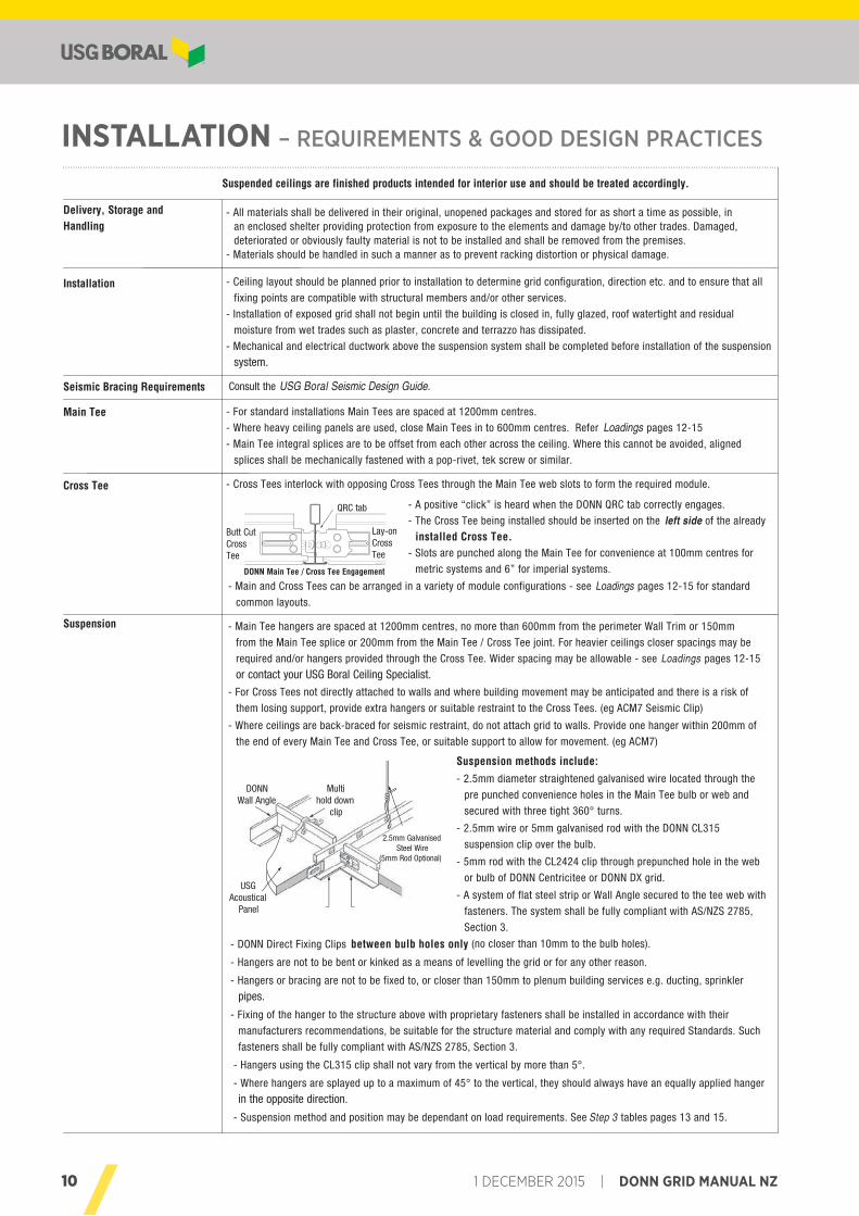
- Cross Tees interlock with opposing Cross Tees through the Main Tee web slots to form the required module.
Requirements andGood Design Practices
DONN Main Tee
DONN CrossTeeUSG
Acoustical Panel
Multihold down
clip
DONNWall Angle
2.5mm GalvanisedSteel Wire
(5mm Rod Optional)
Butt CutCross Tee
Lay-onCross Tee
QRC tab
DONN Main Tee / Cross Tee Engagement
Suspended ceilings are finished products intended for interior use and should be treated accordingly.
Suspension methods include:- 2.5mm diameter straightened galvanised wire located through the
pre punched convenience holes in the Main Tee bulb or web and
secured with three tight 360° turns.
- 2.5mm wire or 5mm galvanised rod with the DONN CL315
suspension clip over the bulb.
- 5mm rod with the CL2424 clip through prepunched hole in the web
or bulb of DONN Centricitee or DONN DX grid.
- A system of flat steel strip or Wall Angle secured to the tee web with
fasteners. The system shall be fully compliant with AS/NZS 2785,
Section 3.
- DONN Direct Fixing Clips between bulb holes only (no closer than 10mm to the bulb holes).
- Hangers are not to be bent or kinked as a means of levelling the grid or for any other reason.
- Hangers or bracing are not to be fixed to, or closer than 150mm to plenum building services e.g. ducting, sprinkler
pipes.
- Fixing of the hanger to the structure above with proprietary fasteners shall be installed in accordance with their
manufacturers recommendations, be suitable for the structure material and comply with any required Standards. Such
fasteners shall be fully compliant with AS/NZS 2785, Section 3.
- Hangers using the CL315 clip shall not vary from the vertical by more than 5°.
- Where hangers are splayed up to a maximum of 45° to the vertical, they should always have an equally applied hanger
in the opposite direction.
- Suspension method and position may be dependant on load requirements. See Step 3 tables pages 13 and 15.
- A positive “click” is heard when the DONN QRC tab correctly engages.
- The Cross Tee being installed should be inserted on the left side of the already
installed Cross Tee.- Slots are punched along the Main Tee for convenience at 100mm centres for
metric systems and 6” for imperial systems.
- Main and Cross Tees can be arranged in a variety of module configurations - see Loadings pages 12-15 for standard
common layouts.
- Main Tee hangers are spaced at 1200mm centres, no more than 600mm from the perimeter Wall Trim or 150mm
from the Main Tee splice or 200mm from the Main Tee / Cross Tee joint. For heavier ceilings closer spacings may be
required and/or hangers provided through the Cross Tee. Wider spacing may be allowable - see Loadings pages 12-15
or contact your USG Boral Ceiling Specialist.
- For Cross Tees not directly attached to walls and where building movement may be anticipated and there is a risk of
them losing support, provide extra hangers or suitable restraint to the Cross Tees. (eg ACM7 Seismic Clip)
- Where ceilings are back-braced for seismic restraint, do not attach grid to walls. Provide one hanger within 200mm of
the end of every Main Tee and Cross Tee, or suitable support to allow for movement. (eg ACM7)
DONN® BrandExposed Grid
11DONN GRID MANUAL NZ | 1 DECEMBER 2015
» INSTALLATION
© 2015 11
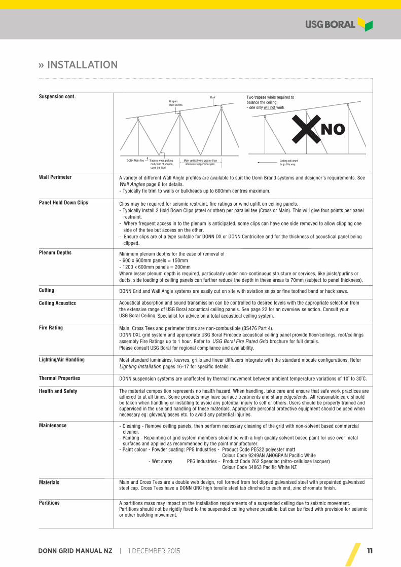
Suspension cont.
DONN Main Tee Trapeze wires pick upmid-point of span tocarry the load
Main vertical wire greater than allowable suspension span.
Hi spansteel purlins
Roof
Ceiling will wantto go this way.
Two trapeze wires required to balance the ceiling.- one only will not work
Wall Perimeter
Panel Hold Down Clips
Plenum Depths
Cutting
Ceiling Acoustics
Fire Rating
Lighting/Air Handling
Thermal Properties
Health and Safety
Maintenance
A variety of different Wall Angle profiles are available to suit the Donn Brand systems and designer’s requirements. See Wall Angles page 6 for details.- Typically fix trim to walls or bulkheads up to 600mm centres maximum.
Clips may be required for seismic restraint, fire ratings or wind uplift on ceiling panels.- Typically install 2 Hold Down Clips (steel or other) per parallel tee (Cross or Main). This will give four points per panel restraint.- Where frequent access in to the plenum is anticipated, some clips can have one side removed to allow clipping one side of the tee but access on the other.- Ensure clips are of a type suitable for DONN DX or DONN Centricitee and for the thickness of acoustical panel being clipped.
Minimum plenum depths for the ease of removal of- 600 x 600mm panels = 150mm- 1200 x 600mm panels = 200mmWhere lesser plenum depth is required, particularly under non-continuous structure or services, like joists/purlins or ducts, side loading of ceiling panels can further reduce the depth in these areas to 70mm (subject to panel thickness).
DONN Grid and Wall Angle systems are easily cut on site with aviation snips or fine toothed band or hack saws.
Acoustical absorption and sound transmission can be controlled to desired levels with the appropriate selection from the extensive range of USG Boral acoustical ceiling panels. See page 22 for an overview selection. Consult your USG Boral Ceiling Specialist for advice on a total acoustical ceiling system.
Main, Cross Tees and perimeter trims are non-combustible (BS476 Part 4).DONN DXL grid system and appropriate USG Boral Firecode acoustical ceiling panel provide floor/ceilings, roof/ceilings assembly Fire Ratings up to 1 hour. Refer to USG Boral Fire Rated Grid brochure for full details.Please consult USG Boral for regional compliance and availability.
Most standard luminaires, louvres, grills and linear diffusers integrate with the standard module configurations. Refer Lighting Installation pages 16-17 for specific details.
DONN suspension systems are unaffected by thermal movement between ambient temperature variations of 10˚ to 30˚C.
The material composition represents no health hazard. When handling, take care and ensure that safe work practices are adhered to at all times. Some products may have surface treatments and sharp edges/ends. All reasonable care should be taken when handling or installing to avoid any potential injury to self or others. Users should be properly trained and supervised in the use and handling of these materials. Appropriate personal protective equipment should be used when necessary eg: gloves/glasses etc. to avoid any potential injuries.
- Cleaning - Remove ceiling panels, then perform necessary cleaning of the grid with non-solvent based commercial cleaner.
- Painting - Repainting of grid system members should be with a high quality solvent based paint for use over metal surfaces and applied as recommended by the paint manufacturer.
- Paint colour - Powder coating: PPG Industries - Product Code PE522 polyester matt Colour Code 9249AN ANOGRAIN Pacific White - Wet spray PPG Industries - Product Code 262 Speedlac (nitro-cellulose lacquer) Colour Code 34063 Pacific White NZ
Main and Cross Tees are a double web design, roll formed from hot dipped galvanised steel with prepainted galvanised steel cap. Cross Tees have a DONN QRC high tensile steel tab clinched to each end, zinc chromate finish.
A partitions mass may impact on the installation requirements of a suspended ceiling due to seismic movement.Partitions should not be rigidly fixed to the suspended ceiling where possible, but can be fixed with provision for seismic or other building movement.
Materials
Partitions
InstallationRequirements andGood Design Practices
DONN® BrandExposed Grid
12 1 DECEMBER 2015 | DONN GRID MANUAL NZ
LOADINGS – MAXIMUM ALLOWABLE – DONN DX 24MM
Max
imum
allo
wab
le lo
ad k
g/m
²
Loadings - Maximum Allowable
DONN DX24mm
System Weights
kg/m2
Hanger Spacing (mm)
1000 1100 1200 1350 1500 1800
Standard 1200mm x 600mm
© 201512
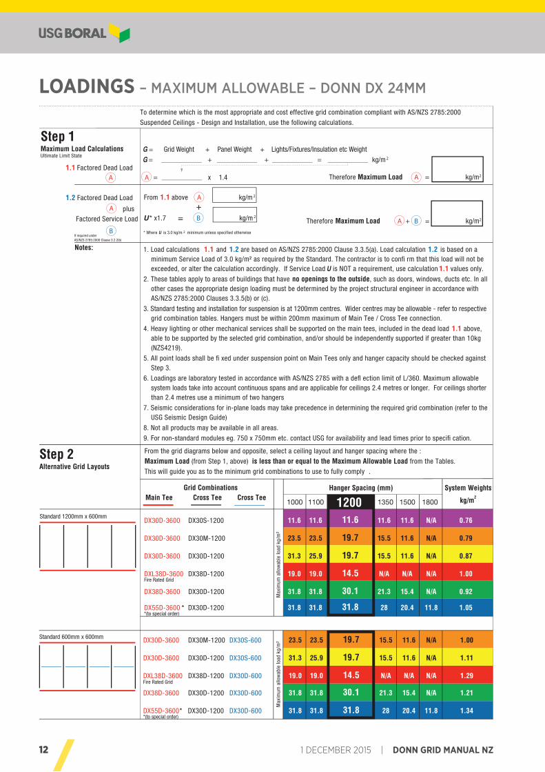
Standard 600mm x 600mm DX30D-3600 DX30M-1200 DX30S-600 23.5 23.5 19.7 15.5 11.6 N/A 1.00
DX30D-3600 DX30D-1200 DX30S-600 31.3 25.9 19.7 15.5 11.6 N/A 1.11
DXL38D-3600 DX38D-1200 DX30D-600 19.0 19.0 14.5 N/A N/A N/A 1.29Fire Rated Grid
DX38D-3600 DX30D-1200 DX30D-600 31.8 31.8 30.1 21.3 15.4 N/A 1.21
DX55D-3600* DX30D-1200 DX30D-600 31.8 31.8 31.8 28 20.4 11.8 1.34*(to special order)
Max
imum
allo
wab
le lo
ad k
g/m
²
DX30D-3600 DX30S-1200 11.6 11.6 11.6 11.6 11.6 N/A 0.76
DX30D-3600 DX30M-1200 23.5 23.5 19.7 15.5 11.6 N/A 0.79
DX30D-3600 DX30D-1200 31.3 25.9 19.7 15.5 11.6 N/A 0.87
DXL38D-3600 DX38D-1200 19.0 19.0 14.5 N/A N/A N/A 1.00Fire Rated Grid
DX38D-3600 DX30D-1200 31.8 31.8 30.1 21.3 15.4 N/A 0.92
DX55D-3600 * DX30D-1200 31.8 31.8 31.8 28 20.4 11.8 1.05*(to special order)
To determine which is the most appropriate and cost effective grid combination compliant with AS/NZS 2785:2000
Suspended Ceilings - Design and Installation, use the following calculations.
Step 1Maximum Load CalculationsUltimate Limit State
G = Grid Weight + Panel Weight + Lights/Fixtures/Insulation etc Weight
G = + + = kg/m 2
1. Load calculations 1.1 and 1.2 are based on AS/NZS 2785:2000 Clause 3.3.5(a). Load calculation 1.2 is based on a minimum Service Load of 3.0 kg/m² as required by the Standard. The contractor is to confi rm that this load will not be exceeded, or alter the calculation accordingly. If Service Load U is NOT a requirement, use calculation 1.1 values only.
2. These tables apply to areas of buildings that have no openings to the outside, such as doors, windows, ducts etc. In all other cases the appropriate design loading must be determined by the project structural engineer in accordance with AS/NZS 2785:2000 Clauses 3.3.5(b) or (c).
3. Standard testing and installation for suspension is at 1200mm centres. Wider centres may be allowable - refer to respective grid combination tables. Hangers must be within 200mm maximum of Main Tee / Cross Tee connection.
4. Heavy lighting or other mechanical services shall be supported on the main tees, included in the dead load 1.1 above, able to be supported by the selected grid combination, and/or should be independently supported if greater than 10kg (NZS4219).
5. All point loads shall be fi xed under suspension point on Main Tees only and hanger capacity should be checked against Step 3.
6. Loadings are laboratory tested in accordance with AS/NZS 2785 with a defl ection limit of L/360. Maximum allowable system loads take into account continuous spans and are applicable for ceilings 2.4 metres or longer. For ceilings shorter than 2.4 metres use a minimum of two hangers
7. Seismic considerations for in-plane loads may take precedence in determining the required grid combination (refer to the USG Seismic Design Guide)
8. Not all products may be available in all areas.
9. For non-standard modules eg. 750 x 750mm etc. contact USG for availability and lead times prior to specifi cation.
Notes:
Step 2Alternative Grid Layouts
From the grid diagrams below and opposite, select a ceiling layout and hanger spacing where the :
Maximum Load (from Step 1, above) is less than or equal to the Maximum Allowable Load from the Tables.
This will guide you as to the minimum grid combinations to use to fully comply .
Therefore Maximum Load A = kg/m2
1.1 Factored Dead Load
Main Tee Cross Tee Cross TeeGrid Combinations
A
Therefore Maximum Load A + B = kg/m2
A = x 1.4
From 1.1 above A kg/m 21.2 Factored Dead Load
plus
* Where U is 3.0 kg/m 2 minimum unless specified otherwise
A Factored Service Load
If required under AS/NZS 2785:2000 Clause 3.2.2(b)
B
U * x1.7 B kg/m 2
+=
13DONN GRID MANUAL NZ | 1 DECEMBER 2015
» LOADINGS – MAXIMUM ALLOWABLE – DONN DX 24MM
© 2015 13
Loadings - Maximum Allowable
DONN DX24mm
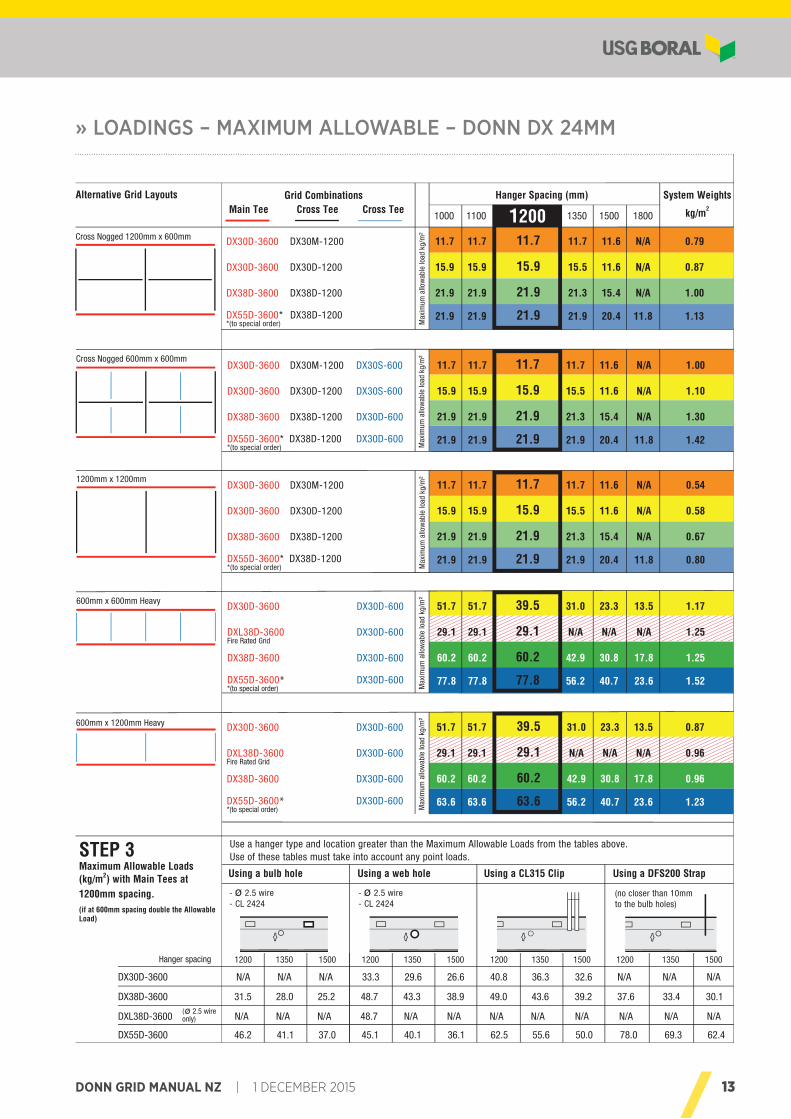
600mm x 1200mm Heavy DX30D-3600 DX30D-600 51.7 51.7 39.5 31.0 23.3 13.5 0.87
DXL38D-3600 DX30D-600 29.1 29.1 29.1 N/A N/A N/A 0.96Fire Rated Grid
DX38D-3600 DX30D-600 60.2 60.2 60.2 42.9 30.8 17.8 0.96
DX55D-3600* DX30D-600 63.6 63.6 63.6 56.2 40.7 23.6 1.23*(to special order) M
axim
um a
llow
able
load
kg/
m²
STEP 3Maximum Allowable Loads (kg/m2) with Main Tees at 1200mm spacing.(if at 600mm spacing double the Allowable Load)
Use a hanger type and location greater than the Maximum Allowable Loads from the tables above. Use of these tables must take into account any point loads.
Using a bulb hole Using a web hole Using a CL315 Clip Using a DFS200 Strap
Cross Nogged 1200mm x 600mm DX30D-3600 DX30M-1200 11.7 11.7 11.7 11.7 11.6 N/A 0.79
DX30D-3600 DX30D-1200 15.9 15.9 15.9 15.5 11.6 N/A 0.87
DX38D-3600 DX38D-1200 21.9 21.9 21.9 21.3 15.4 N/A 1.00
DX55D-3600* DX38D-1200 21.9 21.9 21.9 21.9 20.4 11.8 1.13*(to special order) M
axim
um a
llow
able
load
kg/
m²
System Weights
kg/m2
Hanger Spacing (mm)
1000 1100 1200 1350 1500 1800
Alternative Grid Layouts
Cross Nogged 600mm x 600mmDX30D-3600 DX30M-1200 DX30S-600 11.7 11.7 11.7 11.7 11.6 N/A 1.00
DX30D-3600 DX30D-1200 DX30S-600 15.9 15.9 15.9 15.5 11.6 N/A 1.10
DX38D-3600 DX38D-1200 DX30D-600 21.9 21.9 21.9 21.3 15.4 N/A 1.30
DX55D-3600* DX38D-1200 DX30D-600 21.9 21.9 21.9 21.9 20.4 11.8 1.42*(to special order) M
axim
um a
llow
able
load
kg/
m²
1200mm x 1200mmDX30D-3600 DX30M-1200 11.7 11.7 11.7 11.7 11.6 N/A 0.54
DX30D-3600 DX30D-1200 15.9 15.9 15.9 15.5 11.6 N/A 0.58
DX38D-3600 DX38D-1200 21.9 21.9 21.9 21.3 15.4 N/A 0.67
DX55D-3600* DX38D-1200 21.9 21.9 21.9 21.9 20.4 11.8 0.80*(to special order) M
axim
um a
llow
able
load
kg/
m²
600mm x 600mm HeavyDX30D-3600 DX30D-600 51.7 51.7 39.5 31.0 23.3 13.5 1.17
DXL38D-3600 DX30D-600 29.1 29.1 29.1 N/A N/A N/A 1.25Fire Rated Grid
DX38D-3600 DX30D-600 60.2 60.2 60.2 42.9 30.8 17.8 1.25
DX55D-3600* DX30D-600 77.8 77.8 77.8 56.2 40.7 23.6 1.52*(to special order) M
axim
um a
llow
able
load
kg/
m²
Main Tee Cross Tee Cross TeeGrid Combinations
1200 1350 1500 1200 1350 1500 1200 1350 1500 1200 1350 1500
- ø 2.5 wire - ø 2.5 wire- CL 2424 - CL 2424
DX30D-3600 N/A N/A N/A 33.3 29.6 26.6 40.8 36.3 32.6 N/A N/A N/A
DX38D-3600 31.5 28.0 25.2 48.7 43.3 38.9 49.0 43.6 39.2 37.6 33.4 30.1
DXL38D-3600 N/A N/A N/A 48.7 N/A N/A N/A N/A N/A N/A N/A N/A
DX55D-3600 46.2 41.1 37.0 45.1 40.1 36.1 62.5 55.6 50.0 78.0 69.3 62.4
(ø 2.5 wire only)
Hanger spacing
(no closer than 10mm to the bulb holes)
14 1 DECEMBER 2015 | DONN GRID MANUAL NZ
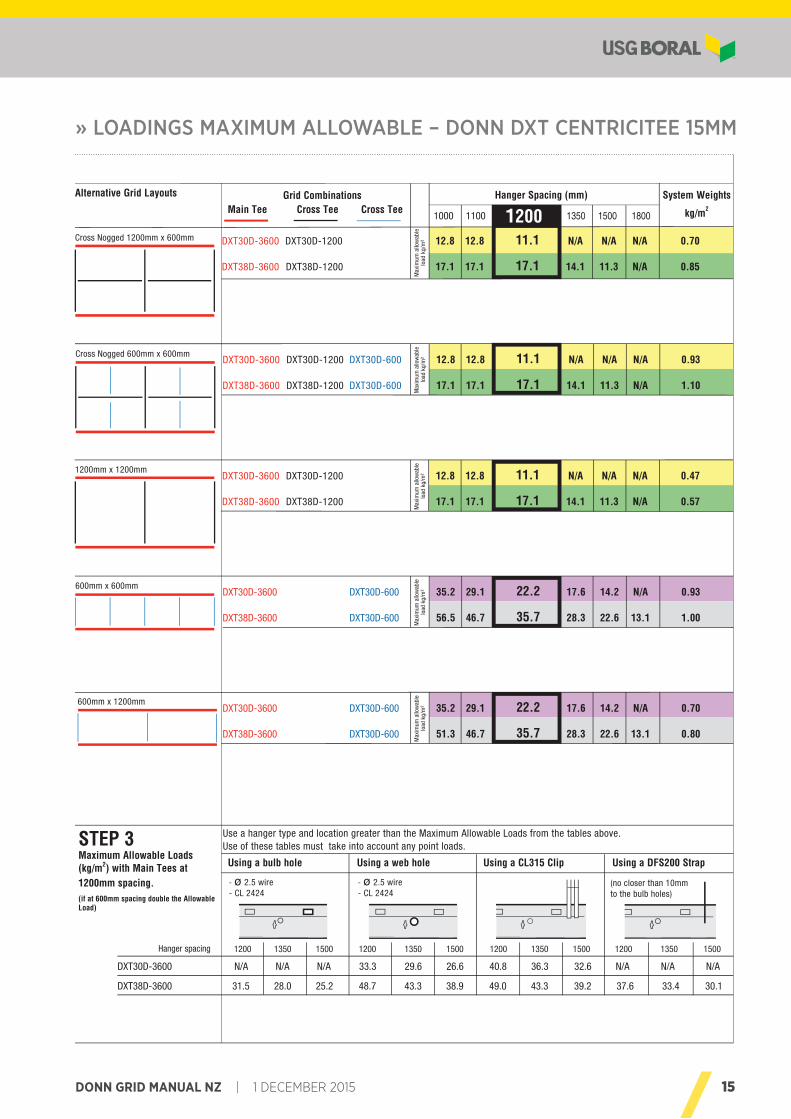
LOADINGS MAXIMUM ALLOWABLE – DONN DXT CENTRICITEE 15MM
Standard 600mm x 600mm
Standard 1200mm x 600mm
Loadings -Maximum Allowable
DONN DXTCentricitee15mm
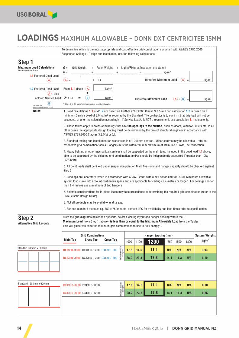
DXT30D-3600 DXT30D-1200 DXT30D-600 17.6 14.5 11.1 N/A N/A N/A 0.93
DXT38D-3600 DXT38D-1200 DXT30D-600 28.2 23.3 17.8 14.1 11.3 N/A 1.10
To determine which is the most appropriate and cost effective grid combination compliant with AS/NZS 2785:2000
Suspended Ceilings - Design and Installation, use the following calculations.
Step 2Alternative Grid Layouts
From the grid diagrams below and opposite, select a ceiling layout and hanger spacing where the :
Maximum Load (from Step 1, above) is less than or equal to the Maximum Allowable Load from the Tables.
This will guide you as to the minimum grid combinations to use to fully comply .
System Weights
kg/m2
Hanger Spacing (mm)
1000 1100 1200 1350 1500 1800
DXT30D-3600 DXT30D-1200 17.6 14.5 11.1 N/A N/A N/A 0.70
DXT38D-3600 DXT38D-1200 28.2 23.3 17.8 14.1 11.3 N/A 0.85
Main Tee Cross Tee Cross TeeGrid Combinations
© 201514
Max
imum
allo
wab
lelo
ad k
g/m
²M
axim
um a
llow
able
load
kg/
m²
Step 1Maximum Load CalculationsUltimate Limit State
G = Grid Weight + Panel Weight + Lights/Fixtures/Insulation etc Weight
G = + + = kg/m2
1. Load calculations 1.1 and 1.2 are based on AS/NZS 2785:2000 Clause 3.3.5(a). Load calculation 1.2 is based on a minimum Service Load of 3.0 kg/m² as required by the Standard. The contractor is to confi rm that this load will not be exceeded, or alter the calculation accordingly. If Service Load U is NOT a requirement, use calculation 1.1 values only.
2. These tables apply to areas of buildings that have no openings to the outside , such as doors, windows, ducts etc. In all other cases the appropriate design loading must be determined by the project structural engineer in accordance with AS/NZS 2785:2000 Clauses 3.3.5(b) or (c).
3. Standard testing and installation for suspension is at 1200mm centres. Wider centres may be allowable - refer to respective grid combination tables. Hangers must be within 200mm maximum of Main Tee / Cross Tee connection.
4. Heavy lighting or other mechanical services shall be supported on the main tees, included in the dead load 1.1 above, able to be supported by the selected grid combination, and/or should be independently supported if greater than 10kg (NZS4219).
5. All point loads shall be fi xed under suspension point on Main Tees only and hanger capacity should be checked against Step 3.
6. Loadings are laboratory tested in accordance with AS/NZS 2785 with a defl ection limit of L/360. Maximum allowable system loads take into account continuous spans and are applicable for ceilings 2.4 metres or longer. For ceilings shorter than 2.4 metres use a minimum of two hangers
7. Seismic considerations for in-plane loads may take precedence in determining the required grid combination (refer to the USG Seismic Design Guide)
8. Not all products may be available in all areas.
9. For non-standard modules eg. 750 x 750mm etc. contact USG for availability and lead times prior to specifi cation.
Notes:
Therefore Maximum Load A = kg/m2
1.1 Factored Dead LoadA
If required under AS/NZS 2785:2000 Clause 3.2.2(b)
Therefore Maximum Load A + B = kg/m2
From 1.1 above A kg/m 21.2 Factored Dead Load
plus
* Where U is 3.0 kg/m2 minimum unless specified otherwise
A Factored Service Load
B
U * x1.7 B kg/m 2
+=
A = x 1.4
15DONN GRID MANUAL NZ | 1 DECEMBER 2015
» LOADINGS MAXIMUM ALLOWABLE – DONN DXT CENTRICITEE 15MM
Cross Nogged 1200mm x 600mm
Cross Nogged 600mm x 600mm
1200mm x 1200mm
Loadings - Maximum Allowable
DONN DXTCentricitee15mm
DXT30D-3600 DXT30D-1200 DXT30D-600 12.8 12.8 11.1 N/A N/A N/A 0.93
DXT38D-3600 DXT38D-1200 DXT30D-600 17.1 17.1 17.1 14.1 11.3 N/A 1.10
DXT30D-3600 DXT30D-1200 12.8 12.8 11.1 N/A N/A N/A 0.47
DXT38D-3600 DXT38D-1200 17.1 17.1 17.1 14.1 11.3 N/A 0.57
DXT30D-3600 DXT30D-600 35.2 29.1 22.2 17.6 14.2 N/A 0.70
DXT38D-3600 DXT30D-600 51.3 46.7 35.7 28.3 22.6 13.1 0.80
600mm x 1200mm
DXT30D-3600 DXT30D-600 35.2 29.1 22.2 17.6 14.2 N/A 0.93
DXT38D-3600 DXT30D-600 56.5 46.7 35.7 28.3 22.6 13.1 1.00
600mm x 600mm
System Weights
kg/m2
Hanger Spacing (mm)
1000 1100 1200 1350 1500 1800
Alternative Grid Layouts
DXT30D-3600 DXT30D-1200 12.8 12.8 11.1 N/A N/A N/A 0.70
DXT38D-3600 DXT38D-1200 17.1 17.1 17.1 14.1 11.3 N/A 0.85
Main Tee Cross Tee Cross TeeGrid Combinations
© 2015 15
Max
imum
allo
wab
lelo
ad k
g/m
²M
axim
um a
llow
able
load
kg/
m²
Max
imum
allo
wab
lelo
ad k
g/m
²M
axim
um a
llow
able
load
kg/
m²
Max
imum
allo
wab
lelo
ad k
g/m
²
STEP 3Maximum Allowable Loads (kg/m2) with Main Tees at 1200mm spacing.(if at 600mm spacing double the Allowable Load)
1200 1350 1500 1200 1350 1500 1200 1350 1500 1200 1350 1500
- ø 2.5 wire - ø 2.5 wire- CL 2424 - CL 2424
DXT30D-3600 N/A N/A N/A 33.3 29.6 26.6 40.8 36.3 32.6 N/A N/A N/A
DXT38D-3600 31.5 28.0 25.2 48.7 43.3 38.9 49.0 43.3 39.2 37.6 33.4 30.1
(no closer than 10mm to the bulb holes)
Hanger spacing
Use a hanger type and location greater than the Maximum Allowable Loads from the tables above. Use of these tables must take into account any point loads.
Using a bulb hole Using a web hole Using a CL315 Clip Using a DFS200 Strap
16 1 DECEMBER 2015 | DONN GRID MANUAL NZ
LIGHTING INSTALLATION
© 201516
24
32
24
25
24
38
24
38
15
38
15
38
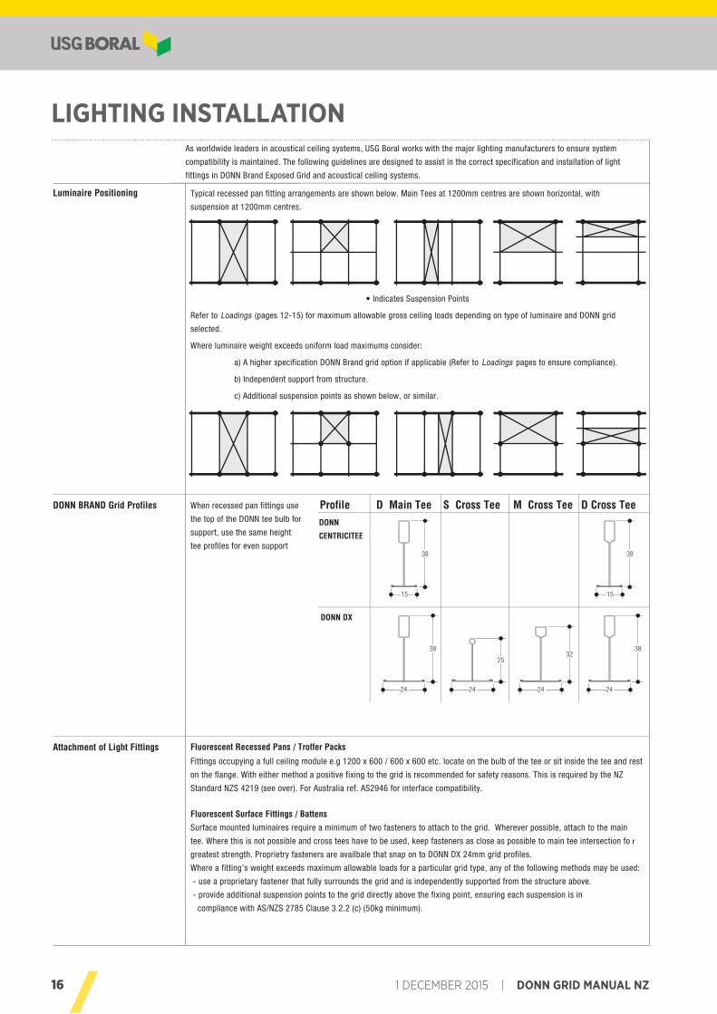
Luminaire Positioning
DONN BRAND Grid Profiles
Attachment of Light Fittings Fluorescent Recessed Pans / Troffer PacksFittings occupying a full ceiling module e.g 1200 x 600 / 600 x 600 etc. locate on the bulb of the tee or sit inside the tee and rest
on the flange. With either method a positive fixing to the grid is recommended for safety reasons. This is required by the NZ
Standard NZS 4219 (see over). For Australia ref. AS2946 for interface compatibility.
Fluorescent Surface Fittings / BattensSurface mounted luminaires require a minimum of two fasteners to attach to the grid. Wherever possible, attach to the main
tee. Where this is not possible and cross tees have to be used, keep fasteners as close as possible to main tee intersection fo r
greatest strength. Proprietry fasteners are availbale that snap on to DONN DX 24mm grid profiles.
Where a fitting’s weight exceeds maximum allowable loads for a particular grid type, any of the following methods may be used:
- use a proprietary fastener that fully surrounds the grid and is independently supported from the structure above.
- provide additional suspension points to the grid directly above the fixing point, ensuring each suspension is in
compliance with AS/NZS 2785 Clause 3.2.2 (c) (50kg minimum).
When recessed pan fittings use
the top of the DONN tee bulb for
support, use the same height
tee profiles for even support
Profile D Main Tee S Cross Tee M Cross Tee D Cross Tee
As worldwide leaders in acoustical ceiling systems, USG Boral works with the major lighting manufacturers to ensure system
compatibility is maintained. The following guidelines are designed to assist in the correct specification and installation of light
fittings in DONN Brand Exposed Grid and acoustical ceiling systems.
DONN
CENTRICITEE
DONN DX
Typical recessed pan fitting arrangements are shown below. Main Tees at 1200mm centres are shown horizontal, with
suspension at 1200mm centres.
• Indicates Suspension Points
Refer to Loadings (pages 12-15) for maximum allowable gross ceiling loads depending on type of luminaire and DONN grid
selected.
Where luminaire weight exceeds uniform load maximums consider:
a) A higher specification DONN Brand grid option if applicable (Refer to Loadings pages to ensure compliance).
b) Independent support from structure.
c) Additional suspension points as shown below, or similar.
Lighting InstallationConstruction Details
17DONN GRID MANUAL NZ | 1 DECEMBER 2015
» CONSTRUCTION DETAILS - LIGHTING INSTALLATION
© 2015 17
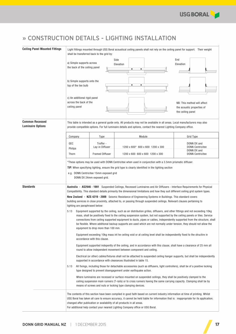
Ceiling Panel Mounted Fittings
Common RecessedLuminaire Options
Standards
This table is intended as a general guide only. All products may not be available in all areas. Local manufacturers may also
provide compatible options. For full luminaire details and options, contact the nearest Lighting Company office.
The contents of this section have been compiled in good faith based on current industry information at time of printing. Whilst
USG Boral has taken all care to ensure accuracy, it cannot be held liable for information that is: inappropriate for its application;
changed after publication or availability of all products in all areas.
For additional help contact your nearest Lighting Company office or USG Boral.
Australia - AS2946 - 1991 Suspended Ceilings, Recessed Luminaires and Air Diffusers - Interface Requirements for Physical
Compatibility. This standard details primarily the dimensional limitations and how they suit different ceiling grid system types.
New Zealand - NZS 4219 - 2009 Seismic Resistance of Engineering Systems in Buildings. This standard covers
building services in close proximity, attached to, or passing through suspended ceilings. Relevant clauses pertaining to
lighting are paraphrased below:
5.13 Equipment supported by the ceiling, such as air distribution grilles, diffusers, and other fittings and not exceeding 10kg
mass, shall be positively fixed to the ceiling suspension system, but not supported by the ceiling panels or tiles. Service
connections from ceiling supported equipment to ducts, pipes or cables, independently supported from the structure, shall
be flexible. Where additional backup supports are used which are not normally under tension, they should not allow the
equipment to drop more than 100 mm.
Equipment exceeding 10kg mass int he ceiling void or at ceiling level shall be independently fixed to the structire in
accordance with this clause.
Equipment supported indepently of the ceiling, and in accordance with this clause, shall have a clearance of 25 mm all
round to allow independent movement between component and ceiling.
Electrical (or other) cables/fixtures shall not be attached to suspended ceiling hanger supports, but shall be independently
supported in accordance with clearances illustrated in table 15.
5.13 All fixings, including those for detachable accessories (such as diffusers, light controllers), shall be of a positive locking
type designed to prevent disengagement under earthquake action.
Where luminaires are recessed or surface-mounted on suspended ceilings, they shall be positively clamped to the
ceiling suspension main runners (T-rails) or to cross runners having the same carrying capacity. Clamping shall be by
means of screws and nuts or locking type clamping devices.
*These options may be used with DONN Centricitee when used in conjunction with a 3.5mm prismatic diffuser.
TIP: When specifying lighting, ensure the grid type is clearly identified in the lighting section
e.g. DONN Centricitee 15mm exposed grid
DONN DX 24mm exposed grid.
Side
Elevation
End
Elevation
NB: This method will affect
the acoustic properties of
the ceiling panel
a) Simple supports across
the back of the ceiling panel
b) Simple supports onto the
top of the tee bulb
c) An additional rigid panel
across the back of the
ceiling panel
Light fittings mounted through USG Boral acoustical ceiling panels shall not rely on the ceiling panel for support. Their weight
shall be transferred back to the grid by:
Construction DetailsLighting Installation
Company Type Module Grid Type
GEC Troffer - DONN DX and Lay-in Diffuser 1200 x 600* 600 x 600 1200 x 300 DONN Centricitee DONN DX andThorn Framed Diffuser 1200 x 600 600 x 600 1200 x 300 DONN Centricitee
Philips
© 2015 17
Ceiling Panel Mounted Fittings
Common RecessedLuminaire Options
Standards
This table is intended as a general guide only. All products may not be available in all areas. Local manufacturers may also
provide compatible options. For full luminaire details and options, contact the nearest Lighting Company office.
The contents of this section have been compiled in good faith based on current industry information at time of printing. Whilst
USG Boral has taken all care to ensure accuracy, it cannot be held liable for information that is: inappropriate for its application;
changed after publication or availability of all products in all areas.
For additional help contact your nearest Lighting Company office or USG Boral.
Australia - AS2946 - 1991 Suspended Ceilings, Recessed Luminaires and Air Diffusers - Interface Requirements for Physical
Compatibility. This standard details primarily the dimensional limitations and how they suit different ceiling grid system types.
New Zealand - NZS 4219 - 2009 Seismic Resistance of Engineering Systems in Buildings. This standard covers
building services in close proximity, attached to, or passing through suspended ceilings. Relevant clauses pertaining to
lighting are paraphrased below:
5.13 Equipment supported by the ceiling, such as air distribution grilles, diffusers, and other fittings and not exceeding 10kg
mass, shall be positively fixed to the ceiling suspension system, but not supported by the ceiling panels or tiles. Service
connections from ceiling supported equipment to ducts, pipes or cables, independently supported from the structure, shall
be flexible. Where additional backup supports are used which are not normally under tension, they should not allow the
equipment to drop more than 100 mm.
Equipment exceeding 10kg mass int he ceiling void or at ceiling level shall be independently fixed to the structire in
accordance with this clause.
Equipment supported indepently of the ceiling, and in accordance with this clause, shall have a clearance of 25 mm all
round to allow independent movement between component and ceiling.
Electrical (or other) cables/fixtures shall not be attached to suspended ceiling hanger supports, but shall be independently
supported in accordance with clearances illustrated in table 15.
5.13 All fixings, including those for detachable accessories (such as diffusers, light controllers), shall be of a positive locking
type designed to prevent disengagement under earthquake action.
Where luminaires are recessed or surface-mounted on suspended ceilings, they shall be positively clamped to the
ceiling suspension main runners (T-rails) or to cross runners having the same carrying capacity. Clamping shall be by
means of screws and nuts or locking type clamping devices.
*These options may be used with DONN Centricitee when used in conjunction with a 3.5mm prismatic diffuser.
TIP: When specifying lighting, ensure the grid type is clearly identified in the lighting section
e.g. DONN Centricitee 15mm exposed grid
DONN DX 24mm exposed grid.
Side
Elevation
End
Elevation
NB: This method will affect
the acoustic properties of
the ceiling panel
a) Simple supports across
the back of the ceiling panel
b) Simple supports onto the
top of the tee bulb
c) An additional rigid panel
across the back of the
ceiling panel
Light fittings mounted through USG Boral acoustical ceiling panels shall not rely on the ceiling panel for support. Their weight
shall be transferred back to the grid by:
Construction DetailsLighting Installation
Company Type Module Grid Type
GEC Troffer - DONN DX and Lay-in Diffuser 1200 x 600* 600 x 600 1200 x 300 DONN Centricitee DONN DX andThorn Framed Diffuser 1200 x 600 600 x 600 1200 x 300 DONN Centricitee
Philips
18 1 DECEMBER 2015 | DONN GRID MANUAL NZ
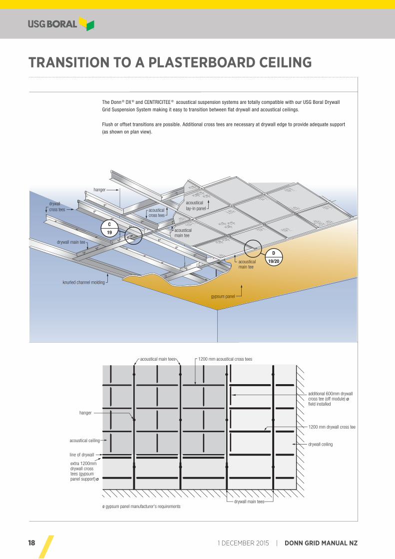
TRANSITION TO A PLASTERBOARD CEILING
© 201518
Transition to aPlasterboard Ceiling
System ComponentsConstruction Details
acoustical main tees 1200 mm acoustical cross tees
acoustical ceilingdrywall ceiling
line of drywall
hanger
1200 mm drywall cross tees
drywall main tees
extra 1200mmdrywall crosstees (gypsumpanel support) ø
additional 600mm drywallcross tee (off module) øfield installed
ø gypsum panel manufacturer's requirements
drywall main tee
knurled channel molding
hanger
acousticalmain tee
acousticalcross tees
acousticallay-in panel
drywall cross tees
acousticalmain tee
gypsum panel
C
19
D
19/20
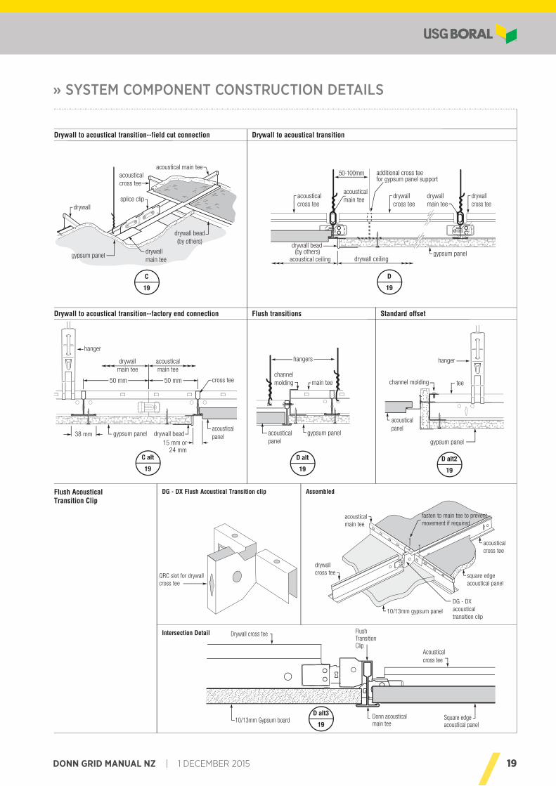
The Donn ® DX ® and CENTRICITEE ® acoustical suspension systems are totally compatible with our USG Boral Drywall
Grid Suspension System making it easy to transition between flat drywall and acoustical ceilings.
Flush or offset transitions are possible. Additional cross tees are necessary at drywall edge to provide adequate support
(as shown on plan view).
19DONN GRID MANUAL NZ | 1 DECEMBER 2015
» SYSTEM COMPONENT CONSTRUCTION DETAILS
© 2015 19
drywallmain tee
drywallcross tee
acousticalmain tee
acoustical ceiling
drywall bead (by others)
drywall ceiling
acousticalcross tee
drywallcross tee
gypsum panel
50-100mm additional cross teefor gypsum panel support
D
19
Construction Details
38 mm15 mm or
24 mm
50 mm 50 mm
gypsum panelacousticalpanel
hanger
cross tee
drywallmain tee
acousticalmain tee
C alt
19
drywall bead
main tee
gypsum panelacousticalpanel
channelmolding
hangers
D alt
19
Acousticalcross tee
Drywall cross tee
Donn acoustical main tee10/13mm Gypsum board
FlushTransitionClip
Square edgeacoustical panel
tee
gypsum panel
acousticalpanel
channel molding
hanger
D alt2
19
Flush AcousticalTransition Clip
acoustical main tee
drywall main tee
drywall
acousticalcross tee
splice clip
gypsum panel
drywall bead(by others)
C
19
drywallcross tee
10/13mm gypsum panel
DG - DXacousticaltransition clip
square edgeacoustical panel
acousticalcross tee
fasten to main tee to preventmovement if required
acoustical main tee
AssembledDG - DX Flush Acoustical Transition clip
QRC slot for drywallcross tee
Intersection Detail
Drywall to acoustical transition--factory end connection Flush transitions Standard offset
Drywall to acoustical transition
D alt3
19
Drywall to acoustical transition--field cut connection
20 1 DECEMBER 2015 | DONN GRID MANUAL NZ
© 201520
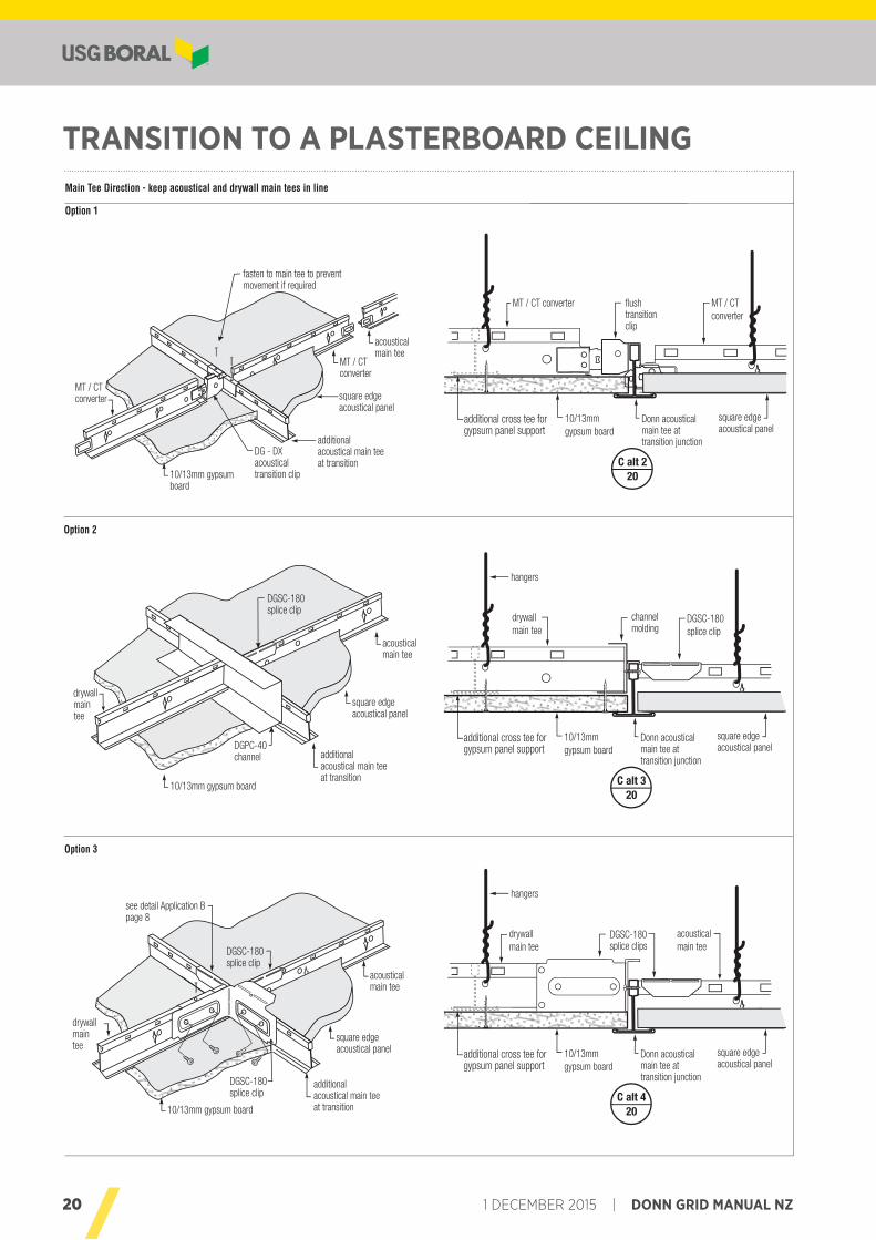
MT / CT converter
Donn acousticalmain tee at transition junction
10/13mmgypsum board
flush transitionclip
square edge acoustical panel
MT / CTconverter
additional cross tee for gypsum panel support
C alt 220
drywall maintee
10/13mm gypsum board
additionalacoustical main tee at transition
square edgeacoustical panel
acousticalmain tee
DGPC-40channel
DGSC-180splice clip
drywall main tee
Donn acousticalmain tee at transition junction
10/13mmgypsum board
channelmolding
square edge acoustical panel
DGSC-180splice clip
additional cross tee for gypsum panel support
hangers
C alt 320
drywall main tee
Donn acousticalmain tee at transition junction
10/13mmgypsum board
DGSC-180splice clips
square edge acoustical panel
acousticalmain tee
additional cross tee for gypsum panel support
hangers
C alt 420
drywall maintee
10/13mm gypsum board
additionalacoustical main tee at transition
square edgeacoustical panel
acousticalmain tee
see detail Application Bpage 8
DGSC-180splice clip
DGSC-180splice clip
Construction Details
Option 1
Option 3
Option 2
Main Tee Direction - keep acoustical and drywall main tees in line
Transition to aPlasterboard CeilingTRANSITION TO A PLASTERBOARD CEILING
21DONN GRID MANUAL NZ | 1 DECEMBER 2015
© 2015 21
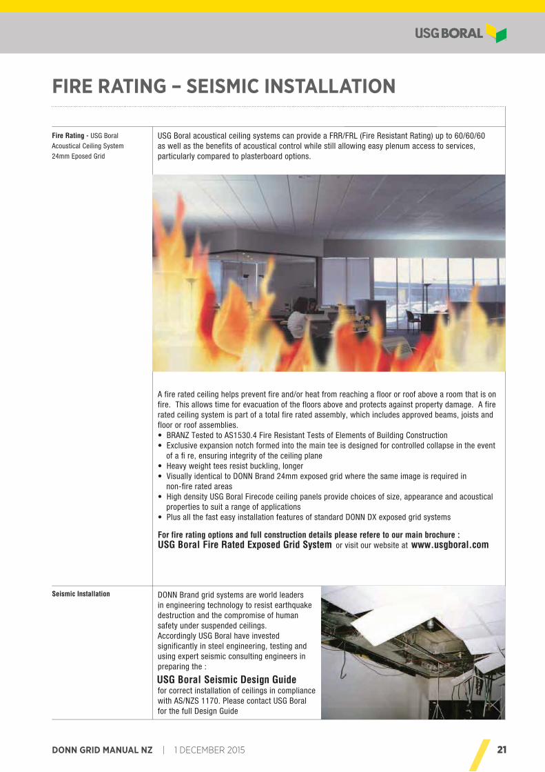
USG Boral acoustical ceiling systems can provide a FRR/FRL (Fire Resistant Rating) up to 60/60/60as well as the benefits of acoustical control while still allowing easy plenum access to services, particularly compared to plasterboard options.
A fire rated ceiling helps prevent fire and/or heat from reaching a floor or roof above a room that is on fire. This allows time for evacuation of the floors above and protects against property damage. A fire rated ceiling system is part of a total fire rated assembly, which includes approved beams, joists and floor or roof assemblies.• BRANZ Tested to AS1530.4 Fire Resistant Tests of Elements of Building Construction• Exclusive expansion notch formed into the main tee is designed for controlled collapse in the event
of a fi re, ensuring integrity of the ceiling plane• Heavy weight tees resist buckling, longer• Visually identical to DONN Brand 24mm exposed grid where the same image is required in
non-fire rated areas• High density USG Boral Firecode ceiling panels provide choices of size, appearance and acoustical
properties to suit a range of applications• Plus all the fast easy installation features of standard DONN DX exposed grid systems
For fire rating options and full construction details please refere to our main brochure : USG Boral Fire Rated Exposed Grid System or visit our website at www.usgboral.com
Fire Rating - USG Boral
Acoustical Ceiling System
24mm Eposed Grid
Seismic Installation DONN Brand grid systems are world leadersin engineering technology to resist earthquake destruction and the compromise of humansafety under suspended ceilings. Accordingly USG Boral have invested significantly in steel engineering, testing and using expert seismic consulting engineers in preparing the :
USG Boral Seismic Design Guidefor correct installation of ceilings in compliance with AS/NZS 1170. Please contact USG Boralfor the full Design Guide
-Fire Rating-Seismic Installation
DONN ExposedGrid Systems
FIRE RATING – SEISMIC INSTALLATION
22 1 DECEMBER 2015 | DONN GRID MANUAL NZ
™or …………………………………………………………………………………………………………………………………………………………………………………………………
USG Boral Acoustical Ceiling Panels
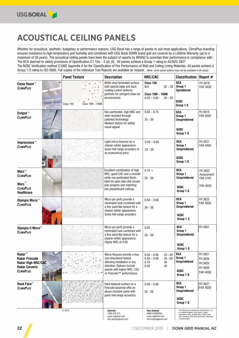
Whether for acoustical, aesthetic, budgetary or performance reasons, USG Boral has a range of panels to suit most applications. ClimaPlus branding ensures resistance to high temperature and humidity and combined with USG Boral DONN brand grid are covered by a Lifetime Warranty (up to a maximum of 30 years). The acoustical ceiling panels have been the subject of reports by BRANZ to ascertain their performance in compliance with : The BCA deemed to satisfy provisions of Specification C1.10a – 3 (a) (ii). All panels achieve a Group 1 rating to AS/NZS 3837 The NZBC Verification method C/VM2 Appendix A for the Classification of Fire Performance of Wall and Ceiling Lining Materials. All panels achieve a Group 1-S rating to ISO 5660. Full copies of the individual Test Reports are available on request. (Note: some panel options may not be available in all areas)
Clean Room™ CLIMAPLUS
Panel Texture Report # Classification Description White vinyl laminated surface with special edge and back coating control airborne particles for stringent clean air environments
BCA Group 1 Sprinklered
Class 100 Class 10M – 100M
Eclipse™ CLIMAPLUS
Non-perforated, high NRC and stain resistant through patented technology. Medium texture for added visual appeal
FH 3619 FAR 4030
BCA Group 1 Unsprinklered
Olympia Micro™ CLIMAPLUS
FH 3623 FAR 4030
Micro pin perfs provide a minimalist look combined with a fine sand-like texture for a cleaner whiter appearance. Good mid-range acoustics.
BCA Group 1 Unsprinklered
Radar™ Radar Firecode Radar High NRC/CAC Radar Ceramic CLIMAPLUS
FH 3621 FH 3625 FH 3625 FH 3626 FAR 4030
Micro-fissures provide a true non-directional texture allowing installation in any direction. Options include panels with higher NRC, CAC or Firecode™ performance.
BCA Group 1 Unsprinklered
Rock Face™ CLIMAPLUS
FH 3627 FAR 4030
Hard textured surface on a Firecode basemat offer an abuse resistant panel with good mid-range acoustics.
BCA Group 1 Unsprinklered
FH 3618 FAR 4030
Olympia II Micro™ CLIMAPLUS
FH 4901
Micro pin perfs provide a minimalist look combined with a fine sand-like texture for a cleaner whiter appearance. Higher NRC of 0.65
BCA Group 1 Unsprinklered
FH 3622 Assessment FAR 2781 FAR 4030
Excellent combination of high NRC, good CAC and a smooth white non-perforated finish. Ideal for open plan and closed plan projects and matching into plasterboard ceilings
BCA Group 1 Unsprinklered
Mars™ CLIMAPLUS
Mars™ CLIMAPLUS
Healthcare
Light micro-fissures for a cleaner whiter appearance. Good mid-range acoustics at an economical price.
FH 3621 FAR 4030
BCA Group 1 Unsprinklered
Impressions™ CLIMAPLUS
© 2015 The following are trademarks of USG Interiors, LLC or a related company: Clean Room, Eclipse, Impressions, Mars, Olympia Micro, Radar, Rock Face, ClimaPlus, USG, Boral and blocks, USG Boral in stylised letters
NRC/CAC
0.65 – 0.75 35 - 39
0.50 – 0.60 33 - 39
0.70 + 35 - 39
0.50 – 0.60 30 - 39
0.65 35 - 39
0.50 – 0.60 33 –39 0.50 – 0.60 35 –39 0.70 40 0.50 40
0.50 – 0.60 35 - 39
Class 100 N/A 35 – 39 Class 10M – 100M 0.55 – 0.65 35 - 39 NZBC
Group 1-S
NZBC Group 1-S
NZBC Group 1-S
NZBC Group 1-S
NZBC Group 1-S
NZBC Group 1-S
NZBC Group 1-S
NZBC Group 1-S
Australia 1800 226 215 www.usgboral.com [email protected]
New Zealand 0800 USGBORAL www.usgboral.com [email protected]
ACOUSTICAL CEILING PANELS™or
…………………………………………………………………………………………………………………………………………………………………………………………………
USG Boral Acoustical Ceiling Panels
Whether for acoustical, aesthetic, budgetary or performance reasons, USG Boral has a range of panels to suit most applications. ClimaPlus branding ensures resistance to high temperature and humidity and combined with USG Boral DONN brand grid are covered by a Lifetime Warranty (up to a maximum of 30 years). The acoustical ceiling panels have been the subject of reports by BRANZ to ascertain their performance in compliance with : The BCA deemed to satisfy provisions of Specification C1.10a – 3 (a) (ii). All panels achieve a Group 1 rating to AS/NZS 3837 The NZBC Verification method C/VM2 Appendix A for the Classification of Fire Performance of Wall and Ceiling Lining Materials. All panels achieve a Group 1-S rating to ISO 5660. Full copies of the individual Test Reports are available on request. (Note: some panel options may not be available in all areas)
Clean Room™ CLIMAPLUS
Panel Texture Report # Classification Description White vinyl laminated surface with special edge and back coating control airborne particles for stringent clean air environments
BCA Group 1 Sprinklered
Class 100 Class 10M – 100M
Eclipse™ CLIMAPLUS
Non-perforated, high NRC and stain resistant through patented technology. Medium texture for added visual appeal
FH 3619 FAR 4030
BCA Group 1 Unsprinklered
Olympia Micro™ CLIMAPLUS
FH 3623 FAR 4030
Micro pin perfs provide a minimalist look combined with a fine sand-like texture for a cleaner whiter appearance. Good mid-range acoustics.
BCA Group 1 Unsprinklered
Radar™ Radar Firecode Radar High NRC/CAC Radar Ceramic CLIMAPLUS
FH 3621 FH 3625 FH 3625 FH 3626 FAR 4030
Micro-fissures provide a true non-directional texture allowing installation in any direction. Options include panels with higher NRC, CAC or Firecode™ performance.
BCA Group 1 Unsprinklered
Rock Face™ CLIMAPLUS
FH 3627 FAR 4030
Hard textured surface on a Firecode basemat offer an abuse resistant panel with good mid-range acoustics.
BCA Group 1 Unsprinklered
FH 3618 FAR 4030
Olympia II Micro™ CLIMAPLUS
FH 4901
Micro pin perfs provide a minimalist look combined with a fine sand-like texture for a cleaner whiter appearance. Higher NRC of 0.65
BCA Group 1 Unsprinklered
FH 3622 Assessment FAR 2781 FAR 4030
Excellent combination of high NRC, good CAC and a smooth white non-perforated finish. Ideal for open plan and closed plan projects and matching into plasterboard ceilings
BCA Group 1 Unsprinklered
Mars™ CLIMAPLUS
Mars™ CLIMAPLUS
Healthcare
Light micro-fissures for a cleaner whiter appearance. Good mid-range acoustics at an economical price.
FH 3621 FAR 4030
BCA Group 1 Unsprinklered
Impressions™ CLIMAPLUS
© 2015 The following are trademarks of USG Interiors, LLC or a related company: Clean Room, Eclipse, Impressions, Mars, Olympia Micro, Radar, Rock Face, ClimaPlus, USG, Boral and blocks, USG Boral in stylised letters
NRC/CAC
0.65 – 0.75 35 - 39
0.50 – 0.60 33 - 39
0.70 + 35 - 39
0.50 – 0.60 30 - 39
0.65 35 - 39
0.50 – 0.60 33 –39 0.50 – 0.60 35 –39 0.70 40 0.50 40
0.50 – 0.60 35 - 39
Class 100 N/A 35 – 39 Class 10M – 100M 0.55 – 0.65 35 - 39 NZBC
Group 1-S
NZBC Group 1-S
NZBC Group 1-S
NZBC Group 1-S
NZBC Group 1-S
NZBC Group 1-S
NZBC Group 1-S
NZBC Group 1-S
Australia 1800 226 215 www.usgboral.com [email protected]
New Zealand 0800 USGBORAL www.usgboral.com [email protected]
23DONN GRID MANUAL NZ | 1 DECEMBER 2015
© 2015 23
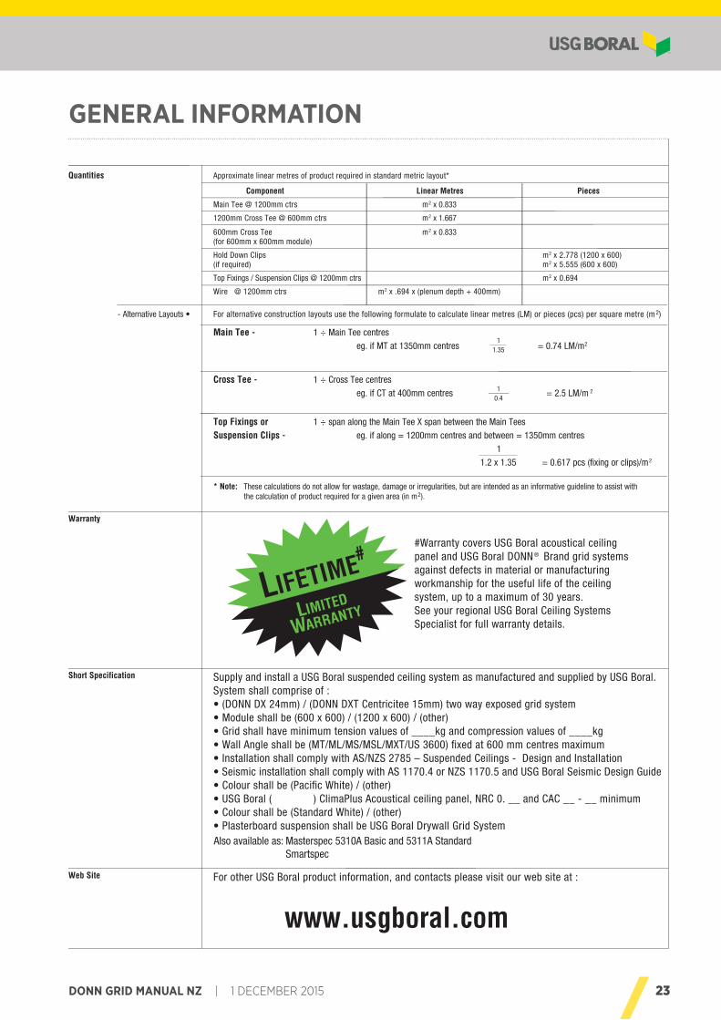
For alternative construction layouts use the following formulate to calculate linear metres (LM) or pieces (pcs) per square metre (m2)
Main Tee - 1 ÷ Main Tee centres
eg. if MT at 1350mm centres = 0.74 LM/m2
Cross Tee - 1 ÷ Cross Tee centres
eg. if CT at 400mm centres = 2.5 LM/m 2
Top Fixings or 1 ÷ span along the Main Tee X span between the Main Tees
Suspension Clips - eg. if along = 1200mm centres and between = 1350mm centres
1
1.2 x 1.35 = 0.617 pcs (fixing or clips)/m2
* Note: These calculations do not allow for wastage, damage or irregularities, but are intended as an informative guideline to assist with the calculation of product required for a given area (in m2).
- Alternative Layouts •
Quantities
Warranty
Short Specification Supply and install a USG Boral suspended ceiling system as manufactured and supplied by USG Boral.System shall comprise of :• (DONN DX 24mm) / (DONN DXT Centricitee 15mm) two way exposed grid system• Module shall be (600 x 600) / (1200 x 600) / (other)• Grid shall have minimum tension values of ____kg and compression values of ____kg• Wall Angle shall be (MT/ML/MS/MSL/MXT/US 3600) fixed at 600 mm centres maximum• Installation shall comply with AS/NZS 2785 – Suspended Ceilings - Design and Installation• Seismic installation shall comply with AS 1170.4 or NZS 1170.5 and USG Boral Seismic Design Guide• Colour shall be (Pacific White) / (other)• USG Boral ( ) ClimaPlus Acoustical ceiling panel, NRC 0. __ and CAC __ - __ minimum• Colour shall be (Standard White) / (other)• Plasterboard suspension shall be USG Boral Drywall Grid System
Web Site For other USG Boral product information, and contacts please visit our web site at :
www.usgboral.com
Approximate linear metres of product required in standard metric layout*
Component Linear Metres Pieces
Main Tee @ 1200mm ctrs m2 x 0.833
1200mm Cross Tee @ 600mm ctrs m2 x 1.667
600mm Cross Tee m2 x 0.833(for 600mm x 600mm module)
Hold Down Clips m2 x 2.778 (1200 x 600)(if required) m2 x 5.555 (600 x 600)
Top Fixings / Suspension Clips @ 1200mm ctrs m2 x 0.694
Wire @ 1200mm ctrs m2 x .694 x (plenum depth + 400mm)
LIFETIME#
LIMITED
WARRANTY
#Warranty covers USG Boral acoustical ceilingpanel and USG Boral DONN ® Brand grid systemsagainst defects in material or manufacturingworkmanship for the useful life of the ceilingsystem, up to a maximum of 30 years.See your regional USG Boral Ceiling SystemsSpecialist for full warranty details.
11.35
10.4
DONN Exposed Grid Systems General InformationGENERAL INFORMATION
Also available as: Masterspec 5310A Basic and 5311A StandardSmartspec

TECHNICAL ENQUIRIES 0800 USGBORAL FOR NZUSG Boral provides technical advice to Builders, Architects, Contractors, Engineers, Regulators and Home Owners throughout New Zealand.
Our friendly team can offer both practical and design input at all levels of the plasterboard industry. Get your next project off on the right track by contacting USG Boral weekdays 8.30am - 5.00pm on 0800 USGBORAL (0800 874 267).
HEALTH AND SAFETYFor information regarding the safe use of USG Boral products and accessories please refer to instructions on the product packaging or contact your local USG Boral Sales Office or TecASSIST® for a current copy of the Material Safety Data Sheet.
This Technical Information Guide is intended to provide general information and should not be used as a substitute for professional advice. There are many variables that can influence construction projects which affect whether a particular construction technique is appropriate. Before proceeding with any project we recommend you obtain professional advice to ascertain the appropriate construction techniques to suit the particular circumstances of your project having regard to the contents of this Installation Manual. We recommend you use qualified tradespersons to install this system.
The technical information contained in this manual was correct at the time of printing. Building systems, details and product availability are, however, subject to change. To ensure the
information you are using is current, USG Boral recommends you review the latest building information available on the USG Boral website. For further information contact TecASSIST® or your nearest USG Boral Sales Office.
© 2015 USG BORAL. All rights reserved. The trademarks USG BORAL, INNOVATION INSPIRED BY YOU, DONN, DX, Centricitee TecASSIST, are trademarks or registered trademarks of USG Boral Building Products or one or more of its affiliates. Clean Room, Eclipse, Impressions, Mars, Olympia Micro, Radar and Rock Face, are trademarks or registered trademarks owned by USG Interiors LLC and used under license.
SALES ENQUIRIES Auckland (09) 270-2595
Wellington (04) 560-4528
Christchurch (03) 365-4245
www.usgboral.com XXX 1 DECEMBER 2015
Available from
0800 POTTERSwww.potters.co.nz