Embed Size (px)
Citation preview
Sustainable housing with mixedweight strategy – a case study Paulo Mendonçaa & Luís Bragançab
a Department of Architecture, University of Minho, Guimarães, Portugal b Civil Engineering Department, University of Minho, Guimarães, Portugal
Abstract The aim of this research work is to demonstrate how an innovative mixedweight solution can lead to achieve more sustainable housing constructions, having in mind that functional aspects related with comfort - thermal, acoustical and natural illumination should be safeguarded. The integrated accomplishment of all these aspects is difficult and not easily predictable. That’s why, for this comparative study, two Test Cells were built and monitored. The proposed mixedweight strategy was evaluated on a Test Cell made with a heavyweight central area, theoretically conceived to lodge the resting areas of a house - bedrooms, bathroom and living room. North and South envelope façades, pavement and covering are lightweight and lodge the less protected areas, destined for working (office, dining room and kitchen) and a corridor / sunspace, respectively. These compartments also take the role of thermal and acoustical barriers to the resting zone. This mixedweight strategy allowed to significantly less environmental cost in comparison to a conventional heavyweight constructive solution using hollow brick and steel reinforced concrete evaluated on a Reference Test Cell and conceived in a monozone layout. The main aspects and results of this study are presented here.
Author Keywords: Sustainable construction. Bioclimatic housing. Thermal zoning.
1. Introduction
In the last centuries, at least until 50 years ago, constructive solutions in Portugal were mixedweight. Heavy stone or massive brick envelope walls (with more then 1000kg/m2), were combined with lightweight timber pavements (approximately 50-100kg/m2), timber/clay dividing walls and timber covering structures (approximately 150-200kg/m2). Recently, with the generalisation of steel reinforced concrete and industrialised hollow brick, the more usual system used in Portugal is the so called “light-weight” concrete (with approximately 350-400kg/m2 for a 0,22m pavement beam and pot slab and a similar weight for a double pane hollow brick envelope wall, generally with insulation on the air gap). In spite of some relative increment on structural performance, the average weight of a housing building is very similar to 50 years ago, but the environmental impact costs per square metre have increased and the possibilities of recycling the components have decreased [1]. There are several strategies that can lead to reduce the environmental impact of buildings. Recycle and re-use of the materials and even the buildings itself are possible, but are not the issues to be discussed on this paper. The necessity to save resources allied to the economical crisis and a growing concern over the environmental issues, has impelled to minimalist-approaches to Architecture and Engineering which, led to its extreme, also implies the reduction to the minimum expression of the constructive elements. This approach, often called "Light-tech" or "Eco-tech", bets on the introduction of more energetically efficient constructive systems and materials. The reduction of the proper weight is essential in the optimization of the energetic costs of construction, but this is normally understood in a limited manner. Some
preconception on the introduction of new materials and innovative construction systems, has impelled that environmental impact reduction efforts concentrates on the production processes of the conventional industrialized materials, based on concrete and hollow brick, rather than by introducing radically new concepts. The strategy proposed and studied here is based on the weight reduction and how it can be achieved by optimizing the architecture conception and the constructive system in a mixedweight innovative strategy [2]. There will be focused two different but complementary aspects: one is a research on optimizing the total primary energy consumption (PEC) of construction materials and components and their transport, the other is based on reducing the energy operating consumptions for maintaining interior thermal comfort, but still using the maximum possible passive solar gains. 1. Optimizing the PEC of the constructive systems and materials - can be achieved by:
Minimal use of materials, specially the inevitably industrialized, such as transparent and translucent (glass or polymers), window frames, infrastructures and insulation; Only when and in the quantity that is strictly necessary, using locally available heavyweight materials as thermal mass for heat storage and sound absorption; Preferable use of natural materials, less transformed and/or recycled; Reducing transport costs by using the most locally available materials as possible; Reducing assembling and disassembling costs by using mechanical fixings; Reducing construction loss factor.
2. Optimizing the “solar passive” design - can be achieved by: Correct study of the relative position of thermal storage elements on the building; Zoning strategy allowing the establishment of different zones of hygrothermal inertia; Reducing the global weight of the building without loosing thermal comfort on the hours that compartments are occupied by indirect gain solar passive systems.
The use of lightweight construction materials and systems can easily allow reach a good environmental profile [2]. But a lightweight housing building in a temperate climate can be problematic, from the point of view of the thermal comfort because of the insufficient thermal inertia. The introduction of some thermal mass is thus essential to achieve comfort with the minimum use of mechanical heating and/or cooling systems and also from the acoustical performance point of view, as acoustic insulation relies essentially on mass, especially for the medium and low frequencies. That’s why a mixedweight system is proposed, with an optimized mass use, in order to allow an intermediate weight between a lightweight solution and a conventional heavyweight solution. The proposed system also pretends to conciliate the thermal, acoustic and natural illumination performance. Apart from its functional efficiency, this strategy can be more consensual then the common prefabricated lightweight constructive systems (so-called prefabricated panels). It is important to refer the fact that this proposal is a system and so the proposed solution here presented and evaluated is just one possible solution for this system.
2. Mixedweight concept principle
The mixedweight housing system was developed essentially based on two distinct approaches: • A research over the façade constructive solutions where the lightweight, opaque materials
can be used by itself or in combination with local heavyweight materials such as stone, compacted earth and adobe, having as objective the optimization of the environmental, energy and economical aspects;
• A research over the architectonical typologies, nominated for the introduction of the concept of interior thermal zoning, as an alternative to the conventional concept of homogeneous thermal inertia, through a solution of mixing thermal inertia. These two solutions, shown in
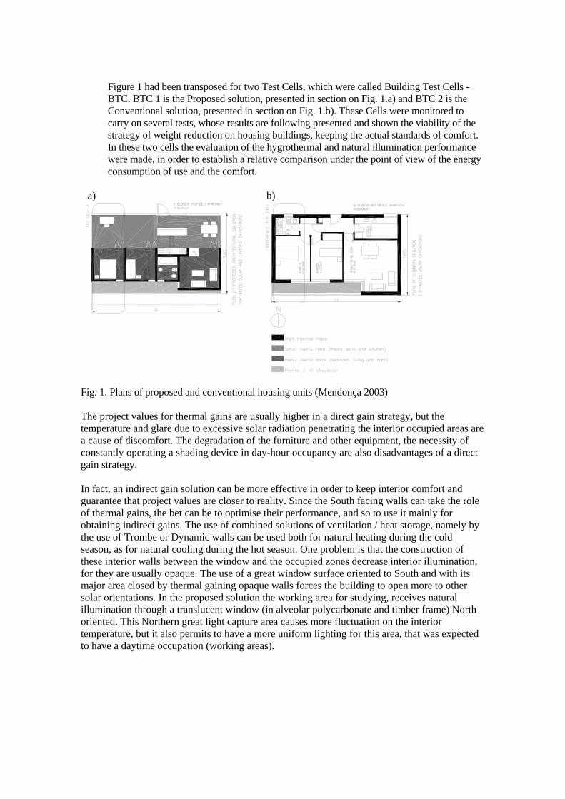
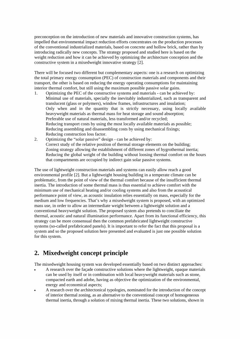
Figure 1 had been transposed for two Test Cells, which were called Building Test Cells - BTC. BTC 1 is the Proposed solution, presented in section on Fig. 1.a) and BTC 2 is the Conventional solution, presented in section on Fig. 1.b). These Cells were monitored to carry on several tests, whose results are following presented and shown the viability of the strategy of weight reduction on housing buildings, keeping the actual standards of comfort. In these two cells the evaluation of the hygrothermal and natural illumination performance were made, in order to establish a relative comparison under the point of view of the energy consumption of use and the comfort.
Fig. 1. Plans of proposed and conventional housing units (Mendonça 2003)
a) b)
The project values for thermal gains are usually higher in a direct gain strategy, but the temperature and glare due to excessive solar radiation penetrating the interior occupied areas are a cause of discomfort. The degradation of the furniture and other equipment, the necessity of constantly operating a shading device in day-hour occupancy are also disadvantages of a direct gain strategy. In fact, an indirect gain solution can be more effective in order to keep interior comfort and guarantee that project values are closer to reality. Since the South facing walls can take the role of thermal gains, the bet can be to optimise their performance, and so to use it mainly for obtaining indirect gains. The use of combined solutions of ventilation / heat storage, namely by the use of Trombe or Dynamic walls can be used both for natural heating during the cold season, as for natural cooling during the hot season. One problem is that the construction of these interior walls between the window and the occupied zones decrease interior illumination, for they are usually opaque. The use of a great window surface oriented to South and with its major area closed by thermal gaining opaque walls forces the building to open more to other solar orientations. In the proposed solution the working area for studying, receives natural illumination through a translucent window (in alveolar polycarbonate and timber frame) North oriented. This Northern great light capture area causes more fluctuation on the interior temperature, but it also permits to have a more uniform lighting for this area, that was expected to have a daytime occupation (working areas).
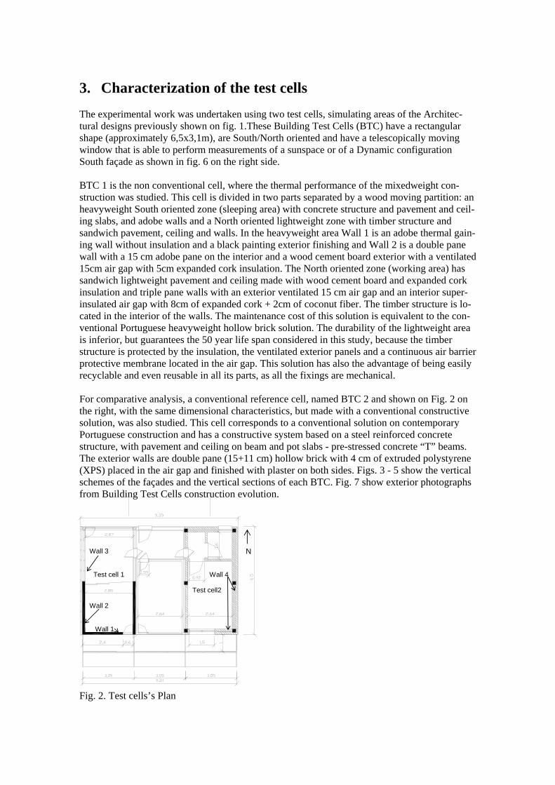
3. Characterization of the test cells The experimental work was undertaken using two test cells, simulating areas of the Architec-tural designs previously shown on fig. 1.These Building Test Cells (BTC) have a rectangular shape (approximately 6,5x3,1m), are South/North oriented and have a telescopically moving window that is able to perform measurements of a sunspace or of a Dynamic configuration South façade as shown in fig. 6 on the right side. BTC 1 is the non conventional cell, where the thermal performance of the mixedweight con-struction was studied. This cell is divided in two parts separated by a wood moving partition: an heavyweight South oriented zone (sleeping area) with concrete structure and pavement and ceil-ing slabs, and adobe walls and a North oriented lightweight zone with timber structure and sandwich pavement, ceiling and walls. In the heavyweight area Wall 1 is an adobe thermal gain-ing wall without insulation and a black painting exterior finishing and Wall 2 is a double pane wall with a 15 cm adobe pane on the interior and a wood cement board exterior with a ventilated 15cm air gap with 5cm expanded cork insulation. The North oriented zone (working area) has sandwich lightweight pavement and ceiling made with wood cement board and expanded cork insulation and triple pane walls with an exterior ventilated 15 cm air gap and an interior super-insulated air gap with 8cm of expanded cork + 2cm of coconut fiber. The timber structure is lo-cated in the interior of the walls. The maintenance cost of this solution is equivalent to the con-ventional Portuguese heavyweight hollow brick solution. The durability of the lightweight area is inferior, but guarantees the 50 year life span considered in this study, because the timber structure is protected by the insulation, the ventilated exterior panels and a continuous air barrier protective membrane located in the air gap. This solution has also the advantage of being easily recyclable and even reusable in all its parts, as all the fixings are mechanical. For comparative analysis, a conventional reference cell, named BTC 2 and shown on Fig. 2 on the right, with the same dimensional characteristics, but made with a conventional constructive solution, was also studied. This cell corresponds to a conventional solution on contemporary Portuguese construction and has a constructive system based on a steel reinforced concrete structure, with pavement and ceiling on beam and pot slabs - pre-stressed concrete “T” beams. The exterior walls are double pane (15+11 cm) hollow brick with 4 cm of extruded polystyrene (XPS) placed in the air gap and finished with plaster on both sides. Figs. 3 - 5 show the vertical schemes of the façades and the vertical sections of each BTC. Fig. 7 show exterior photographs from Building Test Cells construction evolution. Fig. 2. Test cells’s Plan
N Wall 3 Test cell 1 Wall 4
Test cell2 Wall 2 Wall 1
Fig. 3. Test cells’ vertical scheme of the North and South façades.
Fig. 4. Test cells’ vertical scheme of the East and West façades (distances in m). Fig. 5. Vertical sections of test cells 1 and 2 – sunspace configuration (distances in m). Fig. 6. Sunspace and Dynamic wall configurations of the test cells’ South façade
SE
12
Trombe wall Sunspace
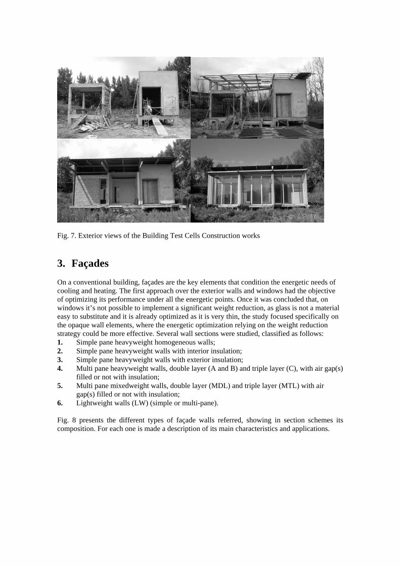
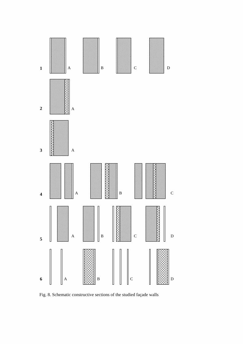
Fig. 7. Exterior views of the Building Test Cells Construction works 3. Façades On a conventional building, façades are the key elements that condition the energetic needs of cooling and heating. The first approach over the exterior walls and windows had the objective of optimizing its performance under all the energetic points. Once it was concluded that, on windows it’s not possible to implement a significant weight reduction, as glass is not a material easy to substitute and it is already optimized as it is very thin, the study focused specifically on the opaque wall elements, where the energetic optimization relying on the weight reduction strategy could be more effective. Several wall sections were studied, classified as follows: 1. Simple pane heavyweight homogeneous walls; 2. Simple pane heavyweight walls with interior insulation; 3. Simple pane heavyweight walls with exterior insulation; 4. Multi pane heavyweight walls, double layer (A and B) and triple layer (C), with air gap(s)
filled or not with insulation; 5. Multi pane mixedweight walls, double layer (MDL) and triple layer (MTL) with air
gap(s) filled or not with insulation; 6. Lightweight walls (LW) (simple or multi-pane).
Fig. 8 presents the different types of façade walls referred, showing in section schemes its composition. For each one is made a description of its main characteristics and applications.
C D
A B 1
2 A
A
3
A B C
4
A C D
B 5
A B C D
6
Fig. 8. Schematic constructive sections of the studied façade walls
Type 1A consists in simple pane walls of stone, compacted earth or brick, traditionally of a great thickness (more then 30cm), without insulation and with an interior and/or exterior layer(s) of mortar. It’s a quite common solution in building of over 50 years, but that was gradually abandoned due to a deficient thermo-hygrometric performance, when its thickness became to be reduced. The great thickness with whom these solutions were used has as an advantage a great contribution in terms of thermal mass. As its performance is conditioned to a great thickness, its use in new buildings is nowadays made impracticable by its great economical cost.
Types 2A, 5B and 5D are common solutions in building refurbishment to increase the thermal resistance of the simple pane walls referred previously. With these solutions, the thermal mass is wasted. Solution 5B, generally with an interior covered with plasterboard and without insulation, permits to use the thermal mass, however it presents more heat losses.
Type 3A is the most common solution of exterior facade wall nowadays used in Portugal. It’s specially used with hollow brick, but in this case the acoustical insulation is poor, due to its reduced mass. A pane of massive brick, stone or compacted earth can improve this solution. On the stone, adobe or massive brick solutions, masonry can only be visible from the interior, as the exterior surface is covered by the insulation and finishing layers (usually polyester net armed plaster over expanded polystyrene). The main disadvantages of this solution are the mechanical vulnerability, poor durability and few finishing types.
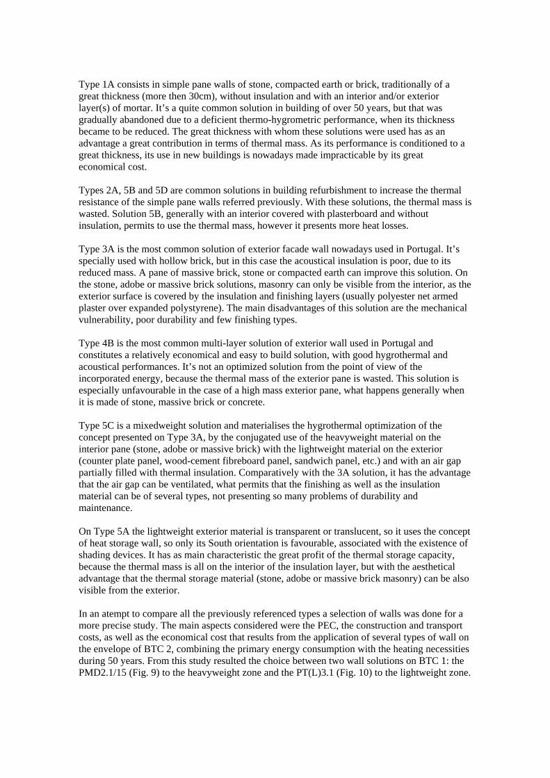
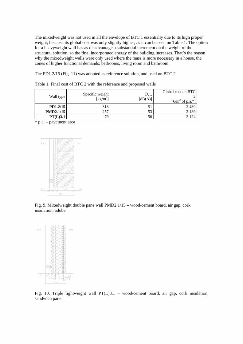
Type 4B is the most common multi-layer solution of exterior wall used in Portugal and constitutes a relatively economical and easy to build solution, with good hygrothermal and acoustical performances. It’s not an optimized solution from the point of view of the incorporated energy, because the thermal mass of the exterior pane is wasted. This solution is especially unfavourable in the case of a high mass exterior pane, what happens generally when it is made of stone, massive brick or concrete. Type 5C is a mixedweight solution and materialises the hygrothermal optimization of the concept presented on Type 3A, by the conjugated use of the heavyweight material on the interior pane (stone, adobe or massive brick) with the lightweight material on the exterior (counter plate panel, wood-cement fibreboard panel, sandwich panel, etc.) and with an air gap partially filled with thermal insulation. Comparatively with the 3A solution, it has the advantage that the air gap can be ventilated, what permits that the finishing as well as the insulation material can be of several types, not presenting so many problems of durability and maintenance. On Type 5A the lightweight exterior material is transparent or translucent, so it uses the concept of heat storage wall, so only its South orientation is favourable, associated with the existence of shading devices. It has as main characteristic the great profit of the thermal storage capacity, because the thermal mass is all on the interior of the insulation layer, but with the aesthetical advantage that the thermal storage material (stone, adobe or massive brick masonry) can be also visible from the exterior. In an atempt to compare all the previously referenced types a selection of walls was done for a more precise study. The main aspects considered were the PEC, the construction and transport costs, as well as the economical cost that results from the application of several types of wall on the envelope of BTC 2, combining the primary energy consumption with the heating necessities during 50 years. From this study resulted the choice between two wall solutions on BTC 1: the PMD2.1/15 (Fig. 9) to the heavyweight zone and the PT(L)3.1 (Fig. 10) to the lightweight zone.
The mixedweight was not used in all the envelope of BTC 1 essentially due to its high proper weight, because its global cost was only slightly higher, as it can be seen on Table 1. The option for a heavyweight wall has as disadvantage a substantial increment on the weight of the structural solution, so the final incorporated energy of the building increases. That’s the reason why the mixedweight walls were only used where the mass is more necessary in a house, the zones of higher functional demands: bedrooms, living room and bathroom. The PD1.2/15 (Fig. 11) was adopted as reference solution, and used on BTC 2. Table 1. Final cost of BTC 2 with the reference and proposed walls
Wall type Specific weight[kg/m2]
Dn,w [dB(A)]
Global cost on BTC 2
[€/m2 of p.a.*] PD1.2/15 313 51 2.439
PMD2.1/15 257 53 2.139 PT(L)3.1 79 50 2.124
* p.a. – pavement area Fig. 9. Mixedweight double pane wall PMD2.1/15 – wood/cement board, air gap, cork insulation, adobe
Fig. 10. Triple lightweight wall PT(L)3.1 – wood/cement board, air gap, cork insulation, sandwich panel
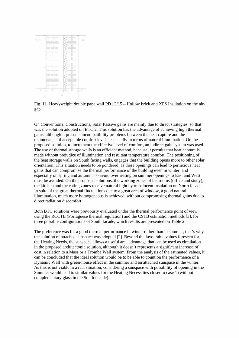
Fig. 11. Heavyweight double pane wall PD1.2/15 – Hollow brick and XPS Insulation on the air-gap On Conventional Constructions, Solar Passive gains are mainly due to direct strategies, so that was the solution adopted on BTC 2. This solution has the advantage of achieving high thermal gains, although it presents incompatibility problems between the heat capture and the maintenance of acceptable comfort levels, especially in terms of natural illumination. On the proposed solution, to increment the effective level of comfort, an indirect gain system was used. The use of thermal storage walls is an efficient method, because it permits that heat capture is made without prejudice of illumination and resultant temperature comfort. The positioning of the heat storage walls on South facing walls, engages that the building opens more to other solar orientation. This situation needs to be pondered, as these openings can lead to pernicious heat gains that can compromise the thermal performance of the building even in winter, and especially on spring and autumn. To avoid overheating on summer openings to East and West must be avoided. On the proposed solutions, the working zones of bedrooms (office and study), the kitchen and the eating zones receive natural light by translucent insulation on North facade. In spite of the great thermal fluctuations due to a great area of window, a good natural illumination, much more homogeneous is achieved, without compromising thermal gains due to direct radiation discomfort.
Both BTC solutions were previously evaluated under the thermal performance point of view, using the RCCTE (Portuguese thermal regulation) and the CSTB estimation methods [3], for three possible configurations of South facade, which results are presented on Table 2. The preference was for a good thermal performance in winter rather than in summer, that’s why the solution of attached sunspace was adopted [2]. Beyond the favourable values foreseen for the Heating Needs, the sunspace allows a useful area advantage that can be used as circulation in the proposed architectonic solution, although it doesn’t represents a significant increase of cost in relation to a Mass or a Trombe Wall system. From the analysis of the estimated values, it can be concluded that the ideal solution would be to be able to count on the performance of a Dynamic Wall with green-house effect in the summer and an attached sunspace in the winter. As this is not viable in a real situation, considering a sunspace with possibility of opening in the Summer would lead to similar values for the Heating Necessities closer to case 1 (without complementary glass in the South façade).
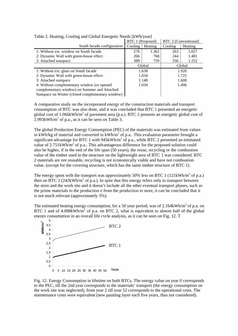
Table 2. Heating, Cooling and Global Energetic Needs [kWh/year] BTC 1 (Proposed) BTC 2 (Conventional)
South facade configuration Cooling Heating Cooling Heating 1: Without ext. window on South facade 276 1.362 263 1.657 2: Dynamic Wall with green-house effect 266 768 244 1.481 3: Attached sunspace 389 759 356 1.252 Global Global 1: Without ext. glass on South facade 1.638 1.920 2: Dynamic Wall with green-house effect 1.034 1.725 3: Attached sunspace 1.148 1.608 4: Without complementary window (or opened complementary window) on Summer and Attached Sunspace on Winter (closed complementary window)
1.034 1.496
A comparative study on the incorporated energy of the construction materials and transport consumption of BTC was also done, and it was concluded that BTC 1 presented an energetic global cost of 1.066kWh/m2 of pavement area (p.a.). BTC 2 presents an energetic global cost of 2.993kWh/m2 of p.a., as it can be seen on Table 3. The global Production Energy Consumption (PEC) of the materials was estimated from values in kWh/kg of material and converted in kWh/m2 of p.a.. This evaluation parameter brought a significant advantage for BTC 1 with 945kWh/m2 of p.a., while BTC 2 presented an estimated value of 2.751kWh/m2 of p.a.. This advantageous difference for the proposed solution could also be higher, if in the end of the life span (50 years), the reuse, recycling or the combustion value of the timber used in the structure on the lightweight area of BTC 1 was considered. BTC 2 materials are not reusable, recycling is not economically viable and have not combustion value. (except for the covering structure, which has the same timber structure of BTC 1). The energy spent with the transport was approximately 50% less on BTC 1 (121kWh/m2 of p.a.) then on BTC 2 (242kWh/m2 of p.a.). In spite that this energy refers only to transport between the store and the work site and it doesn’t include all the other eventual transport phases, such as the prime materials to the production e from the production to store, it can be concluded that it is not much relevant (approximately 5%). The estimated heating energy consumption, for a 50 year period, was of 2.164kWh/m2 of p.a. on BTC 1 and of 4.088kWh/m2 of p.a. on BTC 2, what is equivalent to almost half of the global energy consumption in an overall life cycle analysis, as it can be seen on Fig. 12. T
00,5
11,5
22,5
33,5
44,5
5
0 5 10 15 20 25 30 35 40 45 50
MW
h/m
2
Years
BTC 1
BTC 2
Fig. 12. Energy Consumption in lifetime on both BTCs. The energy value on year 0 corresponds to the PEC, till the 2nd year corresponds to the materials’ transport (the energy consumption on the work site was neglected), from year 2 till year 52 corresponds to the operational costs. The maintenance costs were equivalent (new painting layer each five years, thus not considered).
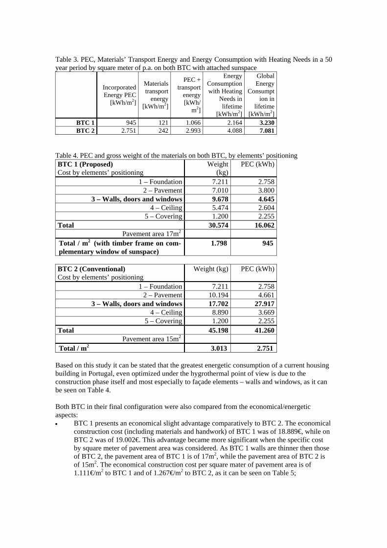
Table 3. PEC, Materials’ Transport Energy and Energy Consumption with Heating Needs in a 50 year period by square meter of p.a. on both BTC with attached sunspace
Incorporated Energy PEC
[kWh/m2]
Materials transport
energy [kWh/m2]
PEC + transport
energy[kWh/
m2]
Energy Consumption with Heating
Needs in lifetime
[kWh/m2]
Global Energy
Consumption in
lifetime [kWh/m2]
BTC 1 945 121 1.066 2.164 3.230 BTC 2 2.751 242 2.993 4.088 7.081
Table 4. PEC and gross weight of the materials on both BTC, by elements’ positioning BTC 1 (Proposed) Cost by elements’ positioning
Weight (kg)
PEC (kWh)
1 – Foundation 7.211 2.758 2 – Pavement 7.010 3.800
3 – Walls, doors and windows 9.678 4.645 4 – Ceiling 5.474 2.604
5 – Covering 1.200 2.255 Total 30.574 16.062
Pavement area 17m2
Total / m2 (with timber frame on com-plementary window of sunspace)
1.798 945
BTC 2 (Conventional) Cost by elements’ positioning
Weight (kg) PEC (kWh)
1 – Foundation 7.211 2.758 2 – Pavement 10.194 4.661
3 – Walls, doors and windows 17.702 27.917 4 – Ceiling 8.890 3.669
5 – Covering 1.200 2.255 Total 45.198 41.260
Pavement area 15m2 Total / m2 3.013 2.751
Based on this study it can be stated that the greatest energetic consumption of a current housing building in Portugal, even optimized under the hygrothermal point of view is due to the construction phase itself and most especially to façade elements – walls and windows, as it can be seen on Table 4.
Both BTC in their final configuration were also compared from the economical/energetic aspects: • BTC 1 presents an economical slight advantage comparatively to BTC 2. The economical
construction cost (including materials and handwork) of BTC 1 was of 18.889€, while on BTC 2 was of 19.002€. This advantage became more significant when the specific cost by square meter of pavement area was considered. As BTC 1 walls are thinner then those of BTC 2, the pavement area of BTC 1 is of 17m2, while the pavement area of BTC 2 is of 15m2. The economical construction cost per square mater of pavement area is of 1.111€/m2 to BTC 1 and of 1.267€/m2 to BTC 2, as it can be seen on Table 5;
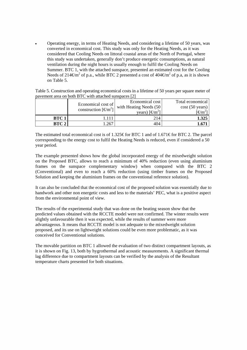
• Operating energy, in terms of Heating Needs, and considering a lifetime of 50 years, was
converted in economical cost. This study was only for the Heating Needs, as it was considered that Cooling Needs on littoral coastal areas of the North of Portugal, where this study was undertaken, generally don’t produce energetic consumptions, as natural ventilation during the night hours is usually enough to fulfil the Cooling Needs on Summer. BTC 1, with the attached sunspace, presented an estimated cost for the Cooling Needs of 214€/m2 of p.a., while BTC 2 presented a cost of 404€/m2 of p.a, as it is shown on Table 5.
Table 5. Construction and operating economical costs in a lifetime of 50 years per square meter of pavement area on both BTC with attached sunspaces [2]
Economical cost of construction [€/m2]
Economical cost with Heating Needs (50
years) [€/m2]
Total economical cost (50 years)
[€/m2]BTC 1 1.111 214 1.325BTC 2 1.267 404 1.671
The estimated total economical cost is of 1.325€ for BTC 1 and of 1.671€ for BTC 2. The parcel corresponding to the energy cost to fulfil the Heating Needs is reduced, even if considered a 50 year period. The example presented shows how the global incorporated energy of the mixedweight solution on the Proposed BTC, allows to reach a minimum of 40% reduction (even using aluminium frames on the sunspace complementary window) when compared with the BTC 2 (Conventional) and even to reach a 60% reduction (using timber frames on the Proposed Solution and keeping the aluminium frames on the conventional reference solution). It can also be concluded that the economical cost of the proposed solution was essentially due to handwork and other non energetic costs and less to the materials’ PEC, what is a positive aspect from the environmental point of view. The results of the experimental study that was done on the heating season show that the predicted values obtained with the RCCTE model were not confirmed. The winter results were slightly unfavourable then it was expected, while the results of summer were more advantageous. It means that RCCTE model is not adequate to the mixedweight solution proposed, and its use on lightweight solutions could be even more problematic, as it was conceived for Conventional solutions. The movable partition on BTC 1 allowed the evaluation of two distinct compartment layouts, as it is shown on Fig. 13, both by hygrothermal and acoustic measurements. A significant thermal lag difference due to compartment layouts can be verified by the analysis of the Resultant temperature charts presented for both situations.
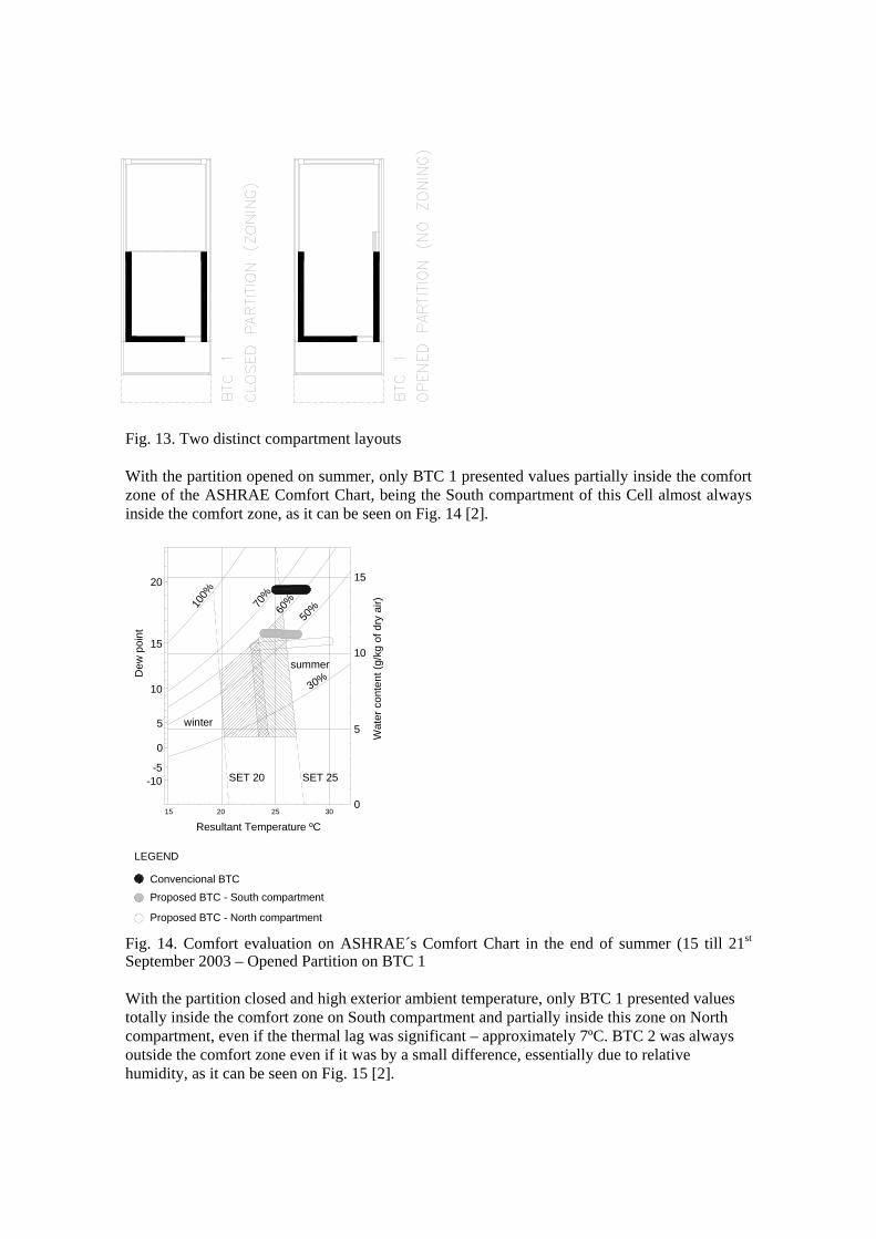
Fig. 13. Compartimentation layouts of BTC 1
Fig. 13. Two distinct compartment layouts With the partition opened on summer, only BTC 1 presented values partially inside the comfort zone of the ASHRAE Comfort Chart, being the South compartment of this Cell almost always inside the comfort zone, as it can be seen on Fig. 14 [2].
Fig. 14. Comfort evaluation on ASHRAE´s Comfort Chart in the end of summer (15 till 21st September 2003 – Opened Partition on BTC 1
30%
50%60
%
winter
summer
SET 20 SET 25
70%
100%
-10-5
0
5
10
15
20
Dew
poi
nt
Resultant Temperature ºC
Wat
er c
onte
nt (g
/kg
of d
ry a
ir)
5
10
15
015 20 25 30
Proposed BTC - South compartment
Convencional BTC
Proposed BTC - North compartment
LEGEND
With the partition closed and high exterior ambient temperature, only BTC 1 presented values totally inside the comfort zone on South compartment and partially inside this zone on North compartment, even if the thermal lag was significant – approximately 7ºC. BTC 2 was always outside the comfort zone even if it was by a small difference, essentially due to relative humidity, as it can be seen on Fig. 15 [2].
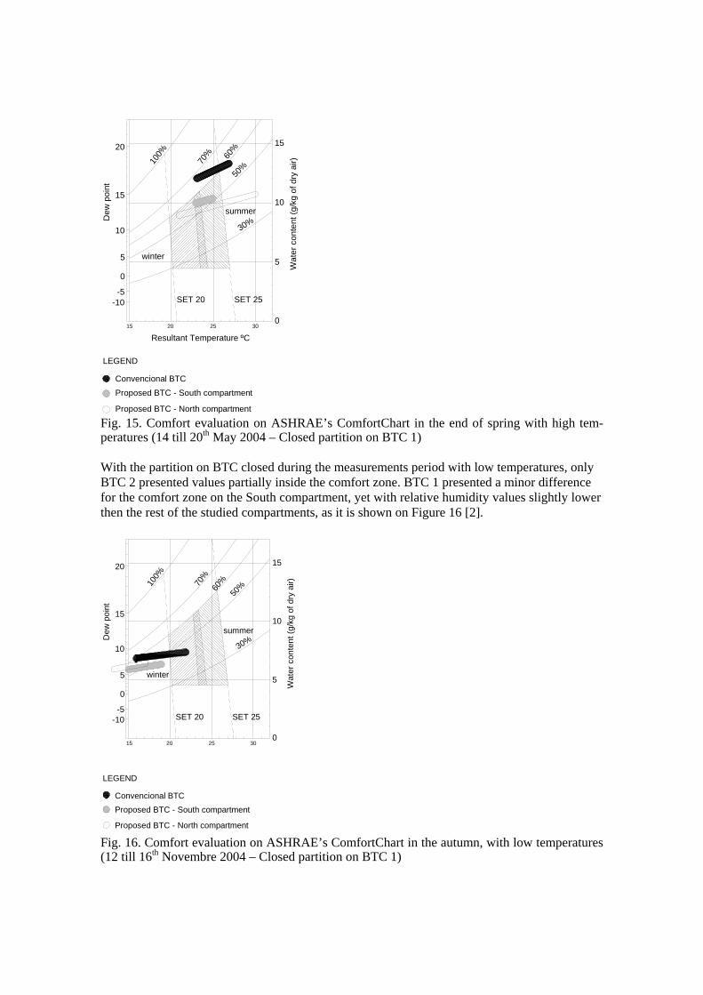
30%50
%
60%
SET 20 SET 25
70%
100%
-10
Fig. 15. Comfort evaluation on ASHRAE’s ComfortChart in the end of spring with high tem-peratures (14 till 20th May 2004 – Closed partition on BTC 1) With the partition on BTC closed during the measurements period with low temperatures, only BTC 2 presented values partially inside the comfort zone. BTC 1 presented a minor difference for the comfort zone on the South compartment, yet with relative humidity values slightly lower then the rest of the studied compartments, as it is shown on Figure 16 [2]. Fig. 16. Comfort evaluation on ASHRAE’s ComfortChart in the autumn, with low temperatures (12 till 16th Novembre 2004 – Closed partition on BTC 1)
-5
0
5 5
10
15
015 20 25 30
20
15
10
Wat
er c
onte
nt (g
/kg
of d
ry a
ir)
Dew
poi
nt
cional BTC
roposed BTC - South compartment
roposed BTC - North compartment
LEGEND
Resultant Temperature ºC
summer
winter
Conven
P
P
30%
50%60
%
SET 20 SET 25
70%
100%
-10-5
0
5
10
15
20
5
10
15
015 20 25 30
Dew
poi
n
Convencional BTC
Proposed BTC - South compartment
Proposed BTC - North compartment
GEND
summer
Wat
er c
onte
nt (g
/kg
of d
ry a
ir)
winter
t
LE
The mixedweight solution studied on the Proposed BTC presented more favourable experimental hygrothermal results during the cooling season and slightly more unfavourable on the heating season. In terms of relative humidity BTC 1 was always more favourable, because measured values were under 60% in most of the cases, while BTC 2 reached values over 70%, specially during Summer, what is going to limit the comfort as well as durability and indoor air quality,. This can be caused by the inferior hygroscopic inertia of the hollow brick in comparison with the adobe.
From the experimental measurements can be concluded that BTC 1 should be improved on its performance during winter, especially on the thermal insulation of the North translucent façade, what is expected to be done on future experimental work. If the study was carried without the attached sunspace on BTC 2, which would be the most obvious solution, this parameter would be more equilibrated, however introducing some unbalance in other parameters such as the economical cost of construction. As the natural illumination performance was much more favourable to BTC 1, the light transmission reduction by the North window caused by the increment of its thermal insulation would even permit a great margin to accomplish this correction without causing natural illumination performance to be more unfavourable then on BTC 2.
During the winter solstice with clear sky conditions, BTC 2 presented excessively high values of natural illumination (more than 2200lux), since 12h till 15h. This is due to the fact that this BTC has direct gains through the South oriented window, with direct incidence of solar radiation on the compartment during the measurements because the sun position on this solstice is low. On Fig. 17 it can be seen that a significant area of the main compartment of BTC 2 was over 2200lux at 15h, what would certainly force the occupants to close all the available shading devices (venetian blinds, louvered sun screens, roller shades, etc.) during almost all day, thus limiting drastically the solar gains caption. Even if with these devices the illumination could be controlled to acceptable values, this would certainly cause that heat gains would be compromised on winter, as the predicted values were based on windows without shading devices or with the shading devices opened for winter [2].
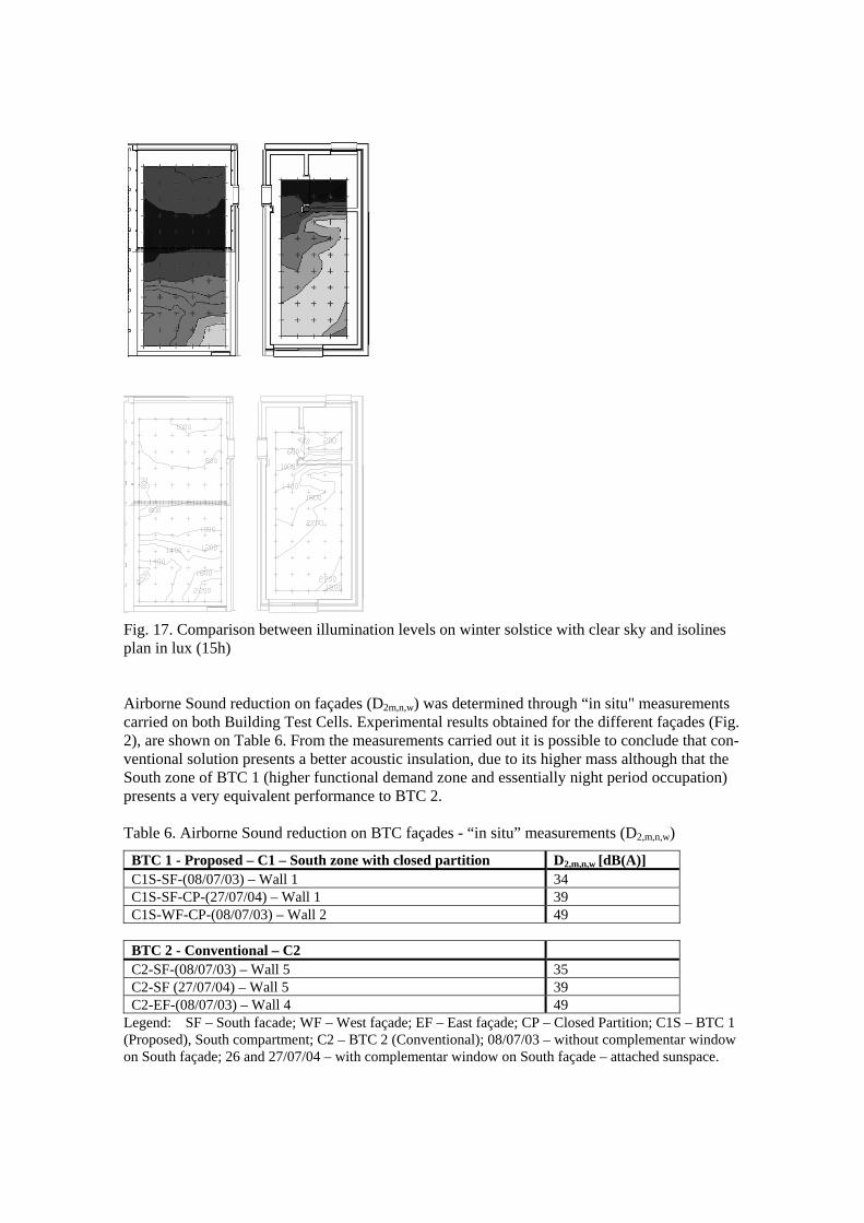
Fig. 17. Comparison between illumination levels on winter solstice with clear sky and isolines plan in lux (15h) Airborne Sound reduction on façades (D2m,n,w) was determined through “in situ" measurements carried on both Building Test Cells. Experimental results obtained for the different façades (Fig. 2), are shown on Table 6. From the measurements carried out it is possible to conclude that con-ventional solution presents a better acoustic insulation, due to its higher mass although that the South zone of BTC 1 (higher functional demand zone and essentially night period occupation) presents a very equivalent performance to BTC 2. Table 6. Airborne Sound reduction on BTC façades - “in situ” measurements (D2,m,n,w)
BTC 1 - Proposed – C1 – South zone with closed partition D2,m,n,w [dB(A)] C1S-SF-(08/07/03) – Wall 1 34 C1S-SF-CP-(27/07/04) – Wall 1 39 C1S-WF-CP-(08/07/03) – Wall 2 49 BTC 2 - Conventional – C2 C2-SF-(08/07/03) – Wall 5 35 C2-SF (27/07/04) – Wall 5 39 C2-EF-(08/07/03) – Wall 4 49
Legend: SF – South facade; WF – West façade; EF – East façade; CP – Closed Partition; C1S – BTC 1 (Proposed), South compartment; C2 – BTC 2 (Conventional); 08/07/03 – without complementar window on South façade; 26 and 27/07/04 – with complementar window on South façade – attached sunspace.
The acoustic measurements show the influence of the window area on the global performance of the South façade of BTC 2, with a window area 54% larger then the South façade of BTC 1, has an airborne sound reduction level 4dB lower. When both South and e East façades of BTC 2 are compared, with the same mass, airborne sound reduction is 18dB lower. The difference of the airborne sound reduction levels between South and West façades of BTC 1 is of 7dB. By the globally positive results achieved on BTC 1, it can be stated that the mixedweight strategy allows satisfactory acoustic insulation. 5. Conclusions This paper show the potentialities associated with the use of lightweight materials combined with locally available heavyweight materials, in order to achieve a good environmental profile. This strategy of reducing the overall environmental impact was called of mixedweight, and relies on a thermal zoning concept and passive solar indirect gain in order to achieve an overall weight reduction without increasing operating energy costs or reducing other functional aspects. From the experimental measurements data analysis it could be concluded that the heavyweight area have a smaller fluctuation and when the partition door is closed, during night-hours, the temperature swing in this area is lower then the reference test cell. Summer campaign measurements also revealed that Cooling Needs were not relevant, so they were not considered (the zone of this study was Guimarães and it is in a Northern temperate area of Portugal – not very far from sea so it still gets some maritime influence). The Heating overall energetic needs were measured and calculated using the method proposed by CSTB (CSTB 1988) and these values were compared with the other energy aspects - primary energy of construction materials (PEC) and materials transport. The example presented in this paper shows how the environmental impact measured on the Pri-mary Energy Consumption of materials in the proposed innovative mixedweight test cell can reach almost a 50% of improvement when compared with a conventional one and still having a similar economical cost (even a little lower). In spite of the increasing evolution that lightweight materials and systems achieved in the recent past, namely to their durability and stability there is still a long way to go through, before these solutions can be widely accepted. Mixing them with heavyweight solutions, and proving the fact that this strategy is environmentally suitable to be used in bioclimatic constructions, even to temperate climates as the South European ones, can be a step forward. It could also be concluded that the solar passive optimized solution is more sustainable in a Sunspace configuration then in a Dynamic wall configuration. Acknowledgements The authors wish to thank FCT (Fundação para a Ciência e Tecnologia – Portugal) for support-ing the Test Cells for Non Conventional Buildings Project.

References [1] Mendonça, P. & Bragança, L. 2003. “Energy Optimization through Thermal Zoning – the
outer skin”; Proceedings of the “Healthy Buildings – 7th International Conference”; School of Design and Environment , National University of Singapore; 7-11 December.
[2] Mendonça, P. 2005. “Living under a second skin – strategies for the environmental impact reduction of Solar Passive Constructions in temperate climates” Doctorate Thesis in Civil Engineering; University of Minho, Civil Engineering Department, Guimarães, Portugal.
[3] CSTB 1988. “Régles Th-BV, régles de calcul du coefficient de besoins de chauffage des logements - annexes”; cahiers du Centre Scientifique et Technique du Bâtiment, livraison 292, cahier 2274; Paris, Septembre.