Embed Size (px)
Citation preview

Swift M15 Series Compound Microscope
Use and Care Manual
\
SWIFT OPTICAL Enduring Quality and Technical Excellence
2
SWIFT M15
Your Swift M15 microscope is an instrument of precision, both optically and mechanically and will last a lifetime with a minimum amount of maintenance. It is built to the highest and most rigid optical and mechanical standards and has many built-in features to insure durability and high performance in the hands of both student and professional users.
Illuminator
Objective
Slide Holder
Head Eyepiece
On/Off Switch
Illuminator Rheostat
Iris Diaphragm
Mechanical
Stage Control
Coarse Focus
Control
Diopter
Adjustment
Fine Focus
Control
Arm
Base
Nosepiece
3
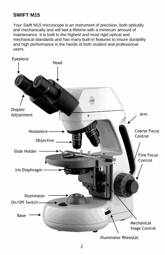
COMPONENTS OF THE MICROSCOPE
ARM – the vertical column (attached to the base) which supports the stage, and contains the coarse and fine adjusting knobs and mechanism. BASE – the housing and platform of the instrument to which the arm is attached. The base stands on rubber feet and contains the illuminator assembly. COARSE FOCUS – the larger, outside knob of the focus control which facilitates rapid and heavy movement of the focusing mechanism. In order to prevent gear damage, the focus control is equipped with an upper limit stopper that protects the high magnification objectives and slides. COAXIAL CONTROLS – the focusing mechanism moves the stage up and down to bring the specimen into focus. The coaxial focusing system combines both the coarse and fine focus into one knob located on both sides of the microscope. The control is designed for a continuous operation over the range of the stage movement. The system is also furnished with a tension control to prevent “stage drift”.
CONDENSER – the function of the condenser is to provide full illumination to the specimen plane and to enhance the resolution and contrast of the object being viewed. The standard condenser of the M15 Series has a numerical aperture of 1.25 with filter carrier and iris diaphragm. It is mounted in a sub–stage focusing assembly that can be raised or lowered for precise light control. DIOPTER ADJUSTMENT – located on the left eyepiece of the binocular head and is designed to help compensate the difference between the user’s eyes. EYEPIECES – the upper optical element that further magnifies the primary image of the specimen and brings the light rays in focus at the eye-point.
FINE FOCUS – the smaller inner knobs of the focus control which allows
for slow and subtle focusing movement to bring the specimen into sharp
focus. HEAD – the upper portion of the microscope which contains the refracting prisms and the eyepiece tubes which hold the eyepieces. ILLUMINATION – the built-in light source which provides the optical system with light. The M15 Series uses a variable intensity 6V 20W Halogen.
4
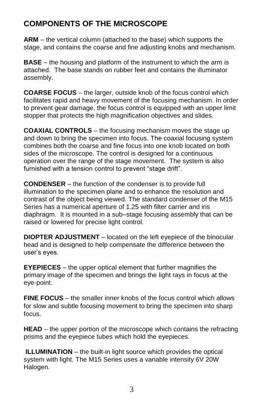
IRIS DIAPHRAGM – a multi-leaf round shaped device which is controlled
by a lever. It is similar to a camera shutter, and is installed under the
condenser. By moving the lever back and forth, the iris diaphragm opens
and closes, increasing and decreasing the contrast of the specimen. If the
image is “washed out” the iris diaphragm is opened too wide. If the image
is too dark the iris is not open wide enough.
NOSEPIECE – the revolving turret that holds the objective lenses,
permitting changes in magnification by rotating different powered
objective lenses into the optical path. The nosepiece must “click” into
place for the objectives to be in proper alignment. OBJECTIVES – the infinity plan optical system which magnifies the primary image of the instrument. Magnifications are typically 4X, 10X, 40X and 100X. SIEDENTOPF – a binocular head design where the interpupillary adjustment (increasing or decreasing the distance between the eyepieces) is achieved by twisting the eyepiece tubes in an up and down arc motion similar to binoculars. STAGE – the table of the microscope where the slide is placed for viewing. This component moves upward and downward when the focusing knobs are turned. The stage of the M15 has a built-in mechanical stage with a below-stage ergonomic “X” and “Y” axis controls. A finger clip holds the slide securely and is designed to be a slow return holder to provide protection to the specimen.
IMPORTANT TERMINOLOGY
“COATED” LENS – in attempting to transmit light through glass, much of the light is lost through reflection. Coating a lens increases the light transmission by reducing or eliminating reflection, thus allowing more light to pass through. COMPOUND MICROSCOPE – a microscope having a primary magnifier (the objective) and a second (the eyepiece) to both conduct light, amplify magnification and convert the image into a field of view easily seen by the human eye.
COVER GLASS – thin glass cut in circles, rectangles, or squares, for
covering the specimen (usually a thickness of 0.15 to 0.17mm). The
majority of specimens should be protected by a cover glass, and must be
covered when using 40XRD or 100XRD objectives.
5
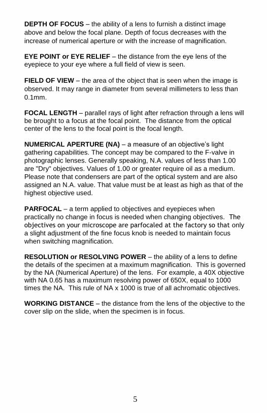
DEPTH OF FOCUS – the ability of a lens to furnish a distinct image
above and below the focal plane. Depth of focus decreases with the
increase of numerical aperture or with the increase of magnification. EYE POINT or EYE RELIEF – the distance from the eye lens of the eyepiece to your eye where a full field of view is seen.
FIELD OF VIEW – the area of the object that is seen when the image is
observed. It may range in diameter from several millimeters to less than
0.1mm. FOCAL LENGTH – parallel rays of light after refraction through a lens will be brought to a focus at the focal point. The distance from the optical center of the lens to the focal point is the focal length.
NUMERICAL APERTURE (NA) – a measure of an objective’s light
gathering capabilities. The concept may be compared to the F-valve in
photographic lenses. Generally speaking, N.A. values of less than 1.00
are "Dry" objectives. Values of 1.00 or greater require oil as a medium.
Please note that condensers are part of the optical system and are also
assigned an N.A. value. That value must be at least as high as that of the
highest objective used.
PARFOCAL – a term applied to objectives and eyepieces when
practically no change in focus is needed when changing objectives. The
objectives on your microscope are parfocaled at the factory so that only
a slight adjustment of the fine focus knob is needed to maintain focus
when switching magnification. RESOLUTION or RESOLVING POWER – the ability of a lens to define the details of the specimen at a maximum magnification. This is governed by the NA (Numerical Aperture) of the lens. For example, a 40X objective with NA 0.65 has a maximum resolving power of 650X, equal to 1000 times the NA. This rule of NA x 1000 is true of all achromatic objectives. WORKING DISTANCE – the distance from the lens of the objective to the cover slip on the slide, when the specimen is in focus.
6
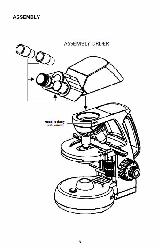
ASSEMBLY
7
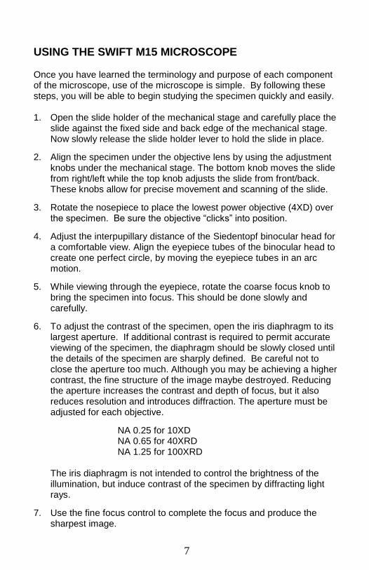
USING THE SWIFT M15 MICROSCOPE
Once you have learned the terminology and purpose of each component of the microscope, use of the microscope is simple. By following these steps, you will be able to begin studying the specimen quickly and easily. 1. Open the slide holder of the mechanical stage and carefully place the
slide against the fixed side and back edge of the mechanical stage. Now slowly release the slide holder lever to hold the slide in place.
2. Align the specimen under the objective lens by using the adjustment knobs under the mechanical stage. The bottom knob moves the slide from right/left while the top knob adjusts the slide from front/back. These knobs allow for precise movement and scanning of the slide.
3. Rotate the nosepiece to place the lowest power objective (4XD) over the specimen. Be sure the objective “clicks” into position.
4. Adjust the interpupillary distance of the Siedentopf binocular head for a comfortable view. Align the eyepiece tubes of the binocular head to create one perfect circle, by moving the eyepiece tubes in an arc motion.
5. While viewing through the eyepiece, rotate the coarse focus knob to bring the specimen into focus. This should be done slowly and carefully.
6. To adjust the contrast of the specimen, open the iris diaphragm to its largest aperture. If additional contrast is required to permit accurate viewing of the specimen, the diaphragm should be slowly closed until the details of the specimen are sharply defined. Be careful not to close the aperture too much. Although you may be achieving a higher contrast, the fine structure of the image maybe destroyed. Reducing the aperture increases the contrast and depth of focus, but it also reduces resolution and introduces diffraction. The aperture must be adjusted for each objective.
NA 0.25 for 10XD NA 0.65 for 40XRD NA 1.25 for 100XRD
The iris diaphragm is not intended to control the brightness of the illumination, but induce contrast of the specimen by diffracting light rays.
7. Use the fine focus control to complete the focus and produce the sharpest image.
8
8. For additional clarity, use the left eye diopter adjustment to correct the differences between the user’s eyes. Set the adjustable left eye diopter at zero. Then focus with the coaxial focusing knob, using your right eye only (close your left eye). Now using your left eye only, adjust the diopter ring until a clear image is seen (close your right eye). The diopter adjustment is now set to the users eyes and will not need to be adjusted again until a different user uses the microscope.
9. Now you can rotate the nosepiece to higher magnification objectives. The objectives are parfocaled so that once the lowest objective (4XD) is focused, only a slight turn of the fine focusing knob is required when changing to 10XD, 40XRD and 100XRD objectives.
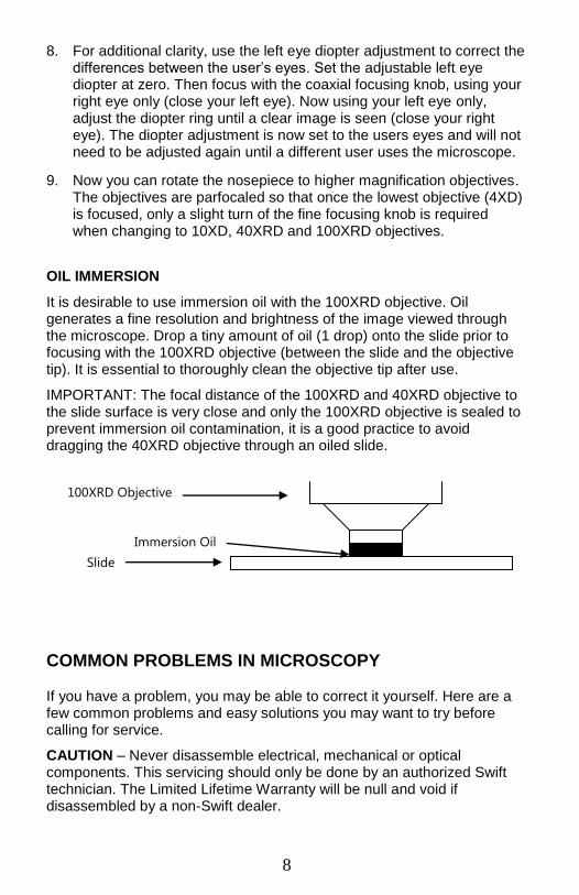
OIL IMMERSION
It is desirable to use immersion oil with the 100XRD objective. Oil generates a fine resolution and brightness of the image viewed through the microscope. Drop a tiny amount of oil (1 drop) onto the slide prior to focusing with the 100XRD objective (between the slide and the objective tip). It is essential to thoroughly clean the objective tip after use.
IMPORTANT: The focal distance of the 100XRD and 40XRD objective to the slide surface is very close and only the 100XRD objective is sealed to prevent immersion oil contamination, it is a good practice to avoid dragging the 40XRD objective through an oiled slide.
COMMON PROBLEMS IN MICROSCOPY
If you have a problem, you may be able to correct it yourself. Here are a few common problems and easy solutions you may want to try before calling for service.
CAUTION – Never disassemble electrical, mechanical or optical components. This servicing should only be done by an authorized Swift technician. The Limited Lifetime Warranty will be null and void if disassembled by a non-Swift dealer.
Immersion Oil
100XRD Objective
Slide
9
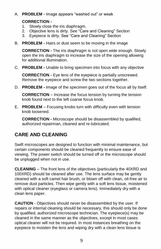
A. PROBLEM - Image appears “washed out” or weak
CORRECTION - 1. Slowly close the iris diaphragm. 2. Objective lens is dirty. See “Care and Cleaning” Section 3. Eyepiece is dirty. See “Care and Cleaning” Section
B. PROBLEM - Hairs or dust seem to be moving in the image
CORRECTION - The iris diaphragm is not open wide enough. Slowly open the iris diaphragm to increase the size of the opening allowing for additional illumination.
C. PROBLEM - Unable to bring specimen into focus with any objective
CORRECTION - Eye lens of the eyepiece is partially unscrewed. Remove the eyepiece and screw the two sections together.
D. PROBLEM - Image of the specimen goes out of the focus all by itself.
CORRECTION – Increase the focus tension by turning the tension knob found next to the left coarse focus knob.
E. PROBLEM – Focusing knobs turn with difficulty even with tension knob loosened.
CORRECTION - Microscope should be disassembled by qualified, authorized repairman, cleaned and re-lubricated.
CARE AND CLEANING
Swift microscopes are designed to function with minimal maintenance, but
certain components should be cleaned frequently to ensure ease of
viewing. The power switch should be turned off or the microscope should
be unplugged when not in use.
CLEANING – The front lens of the objectives (particularly the 40XRD and
100XRD) should be cleaned after use. The lens surface may be gently
cleaned with a soft camel hair brush, or blown off with clean, oil-free air to
remove dust particles. Then wipe gently with a soft lens tissue, moistened
with optical cleaner (eyeglass or camera lens). Immediately dry with a
clean lens paper.
CAUTION - Objectives should never be disassembled by the user. If
repairs or internal cleaning should be necessary, this should only be done
by qualified, authorized microscope technician. The eyepiece(s) may be
cleaned in the same manner as the objectives, except in most cases
optical cleaner will not be required. In most instances breathing on the
eyepiece to moisten the lens and wiping dry with a clean lens tissue is
10
sufficient to clean the surface. Lenses should never be wiped while dry as
this will scratch or otherwise mar the surface of the glass.
The finish of the microscope is hard epoxy and is resistant to acids and
reagents. Clean this surface with a damp cloth and mild detergent.
Periodically, the microscope should be disassembled, cleaned and
lubricated. This should only be done by a qualified, authorized microscope
technician.
DUST COVER AND STORAGE – All microscopes should be protected
from dust by a dust cover when in storage or not in use. A dust cover is
the most cost-effective microscope insurance you can buy. Ensure that
the storage space is tall enough to allow the microscope to be placed into
the cabinet or onto a shelf without making undue contact with the
eyepieces. Never store microscopes in cabinets containing chemicals
which may corrode your microscope. Also, be sure that the objectives are
placed in the lowest possible position and the rotating head is turned
inward and not protruding from the base. Microscopes with mechanical
stages should be adjusted toward the center of the stage to prevent the
moveable arms of the mechanical stage from being damaged during
storage in the cabinet.
HALOGEN REPLACEMENT The Swift M15 is equipped with a 6V 20W halogen illumination system.
The life of the halogen bulb may vary depending on use and intensity. To
prolong the life of the halogen, you should always turn off the unit when
not in use.
WARNING: FOR YOUR SAFETY, TURN SWITCH OFF AND REMOVE PLUG FROM POWER SOURCE OUTLET BEFORE MAINTAINING YOUR MICROSCOPE. a. Carefully lay instrument on its side, taking care to avoid damage to
the specimen slide holder located on top of mechanical stage. b. Loosen large chrome locking screw located on hinged door of
illuminator base.
c. Swing door open to expose the halogen lamp.

11
d. Using a tissue or cloth to gently grasp the halogen bulb, pull straight out of lamp socket.
e. Your microscope requires a 6 volt, 20 watt halogen bulb, available from the dealer from which you purchased your microscope. This is a common microscope bulb, Osram “Xenophot HLX #64250 ESB”
f. Make certain that new bulb is clean, as fingerprints on bulb can affect light transmission. Grasping bulb gently with a tissue or cloth, insert pins straight into lamp socket.
g. Carefully clean lamp to assure that it is clean and free of all
fingerprints.
h. Close hinged door and tighten locking screw.
12
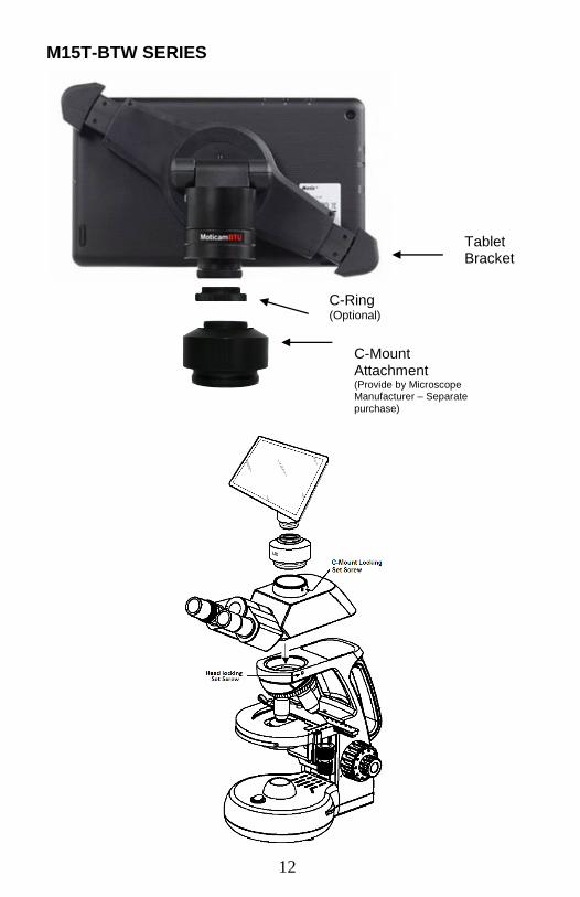
M15T-BTW SERIES
Tablet Bracket
C-Ring (Optional)
C-Mount Attachment (Provide by Microscope Manufacturer – Separate
purchase)
13
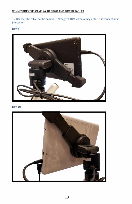
CONNECTING THE CAMERA TO BTW8 AND BTW10 TABLET
1. Connect the tablet to the camera: *Image of BTW camera may differ, but connection is
the same*
BTW8
BTW10
14
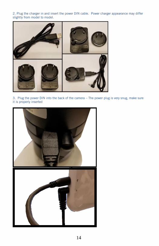
2. Plug the charger in and insert the power DIN cable. Power charger appearance may differ
slightly from model to model.
3. Plug the power DIN into the back of the camera – The power plug is very snug, make sure
it is properly inserted
15
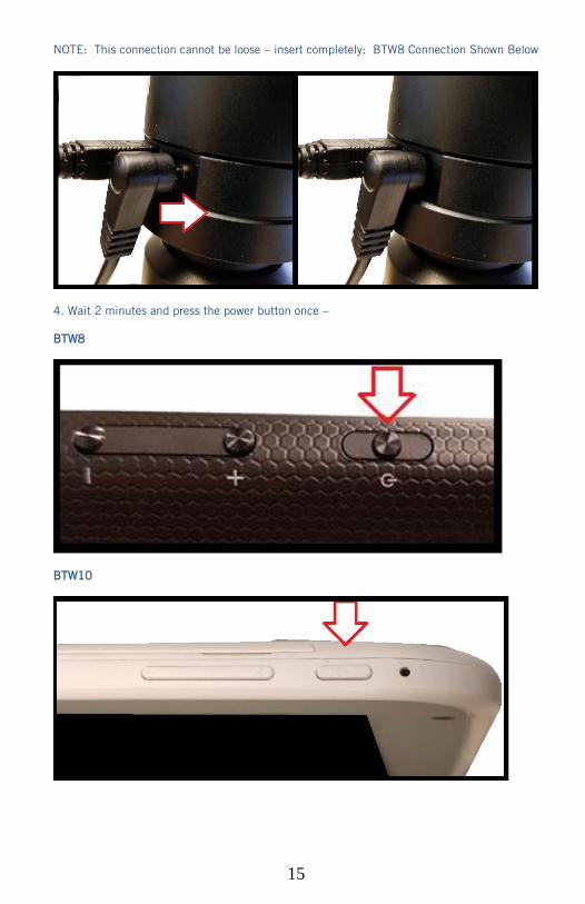
NOTE: This connection cannot be loose – insert completely: BTW8 Connection Shown Below
4. Wait 2 minutes and press the power button once –
BTW8
BTW10
16
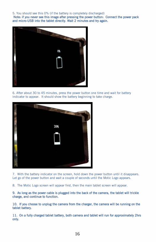
5. You should see this 0% (if the battery is completely discharged)
Note: if you never see this image after pressing the power button: Connect the power pack
and micro-USB into the tablet directly. Wait 2 minutes and try again.
6. After about 30 to 45 minutes, press the power button one time and wait for battery
indicator to appear. It should show the battery beginning to take charge.
7. With the battery indicator on the screen, hold down the power button until it disappears.
Let go of the power button and wait a couple of seconds until the Motic Logo appears.
8. The Motic Logo screen will appear first, then the main tablet screen will appear.
9. As long as the power cable is plugged into the back of the camera, the tablet will trickle
charge, and continue to function.
10. If you choose to unplug the camera from the charger, the camera will be running on the
tablet battery.
11. On a fully charged tablet battery, both camera and tablet will run for approximately 2hrs
only.

17
TABLET ACCESSORIES
HDMI Cable This cable will enable you to connect to an HDMI ready device, to view your tablet on a
larger format. The displayed image will replicate the displayed image of the tablet.
Power Adapter This 5V DC power adapter is for charging your tablet’s battery. It is also used to power
the camera in WiFi mode.
Calibration
Slide
This slide will enable you to calibrate your tablet to your microscope, for accurate
measurements. You do not need to calibrate your microscope in order to begin using
your table/microscope.
C-Ring This ring is used between the camera and c-mount to achieve par-focus. Pre-installed
on MA15602 – C-Mount.
4GB Micro-SD This storage card can be used with your tablet to store images and then transfer them
to your computer. This card is provided as a courtesy and cannot be replaced. *32GB
Max Supported*
Mini USB to
Micro USB
Provides power and feed connection between the tablet and camera. To operate the
camera, move the switch to the camera position.
USB to Micro
USB
This cable when used in conjunction with the power adapter is used to charge the
tablet.
USB to Mini
Power Din
This cable is used to power the camera, in WiFi mode. This cable can also be used to
charge both the tablet and camera at the same time. Keep plugged into camera at all
times, if possible.
L-Wrench Optional Wrench for mounting bracket to Motic branded trinocular microscopes
Please Note: Items included may differ in
appearance from items pictured above
18
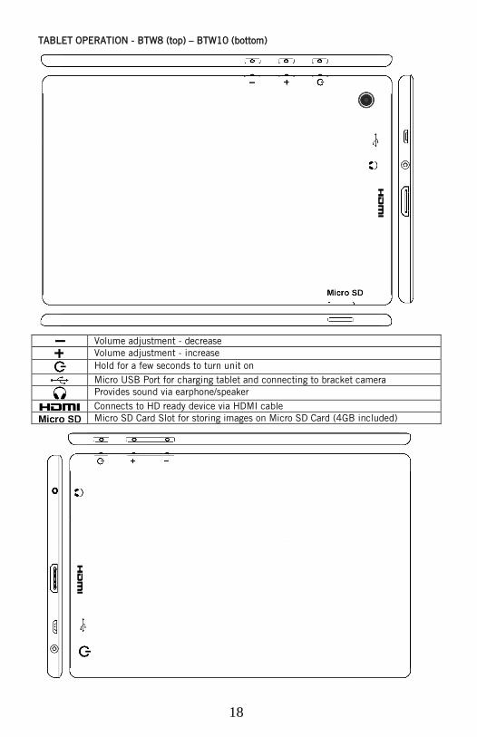
TABLET OPERATION - BTW8 (top) – BTW10 (bottom)
Volume adjustment - decrease
Volume adjustment - increase
Hold for a few seconds to turn unit on
Micro USB Port for charging tablet and connecting to bracket camera
Provides sound via earphone/speaker
Connects to HD ready device via HDMI cable
Micro SD Card Slot for storing images on Micro SD Card (4GB included)
19
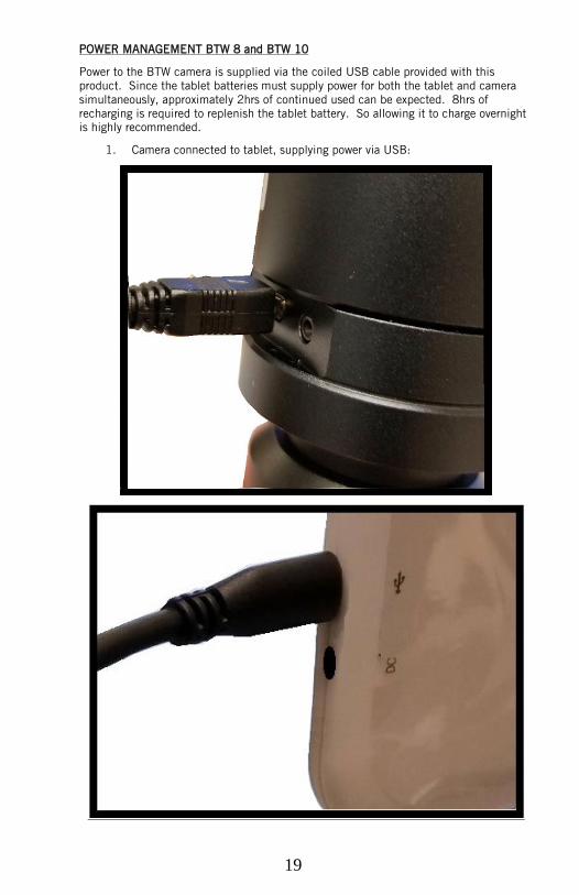
POWER MANAGEMENT BTW 8 and BTW 10
Power to the BTW camera is supplied via the coiled USB cable provided with this
product. Since the tablet batteries must supply power for both the tablet and camera
simultaneously, approximately 2hrs of continued used can be expected. 8hrs of
recharging is required to replenish the tablet battery. So allowing it to charge overnight
is highly recommended.
1. Camera connected to tablet, supplying power via USB:
20
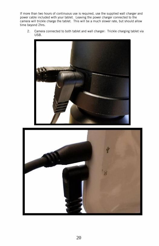
If more than two hours of continuous use is required, use the supplied wall charger and
power cable included with your tablet. Leaving the power charger connected to the
camera will trickle charge the tablet. This will be a much slower rate, but should allow
time beyond 2hrs.
2. Camera connected to both tablet and wall charger: Trickle charging tablet via
USB.
21
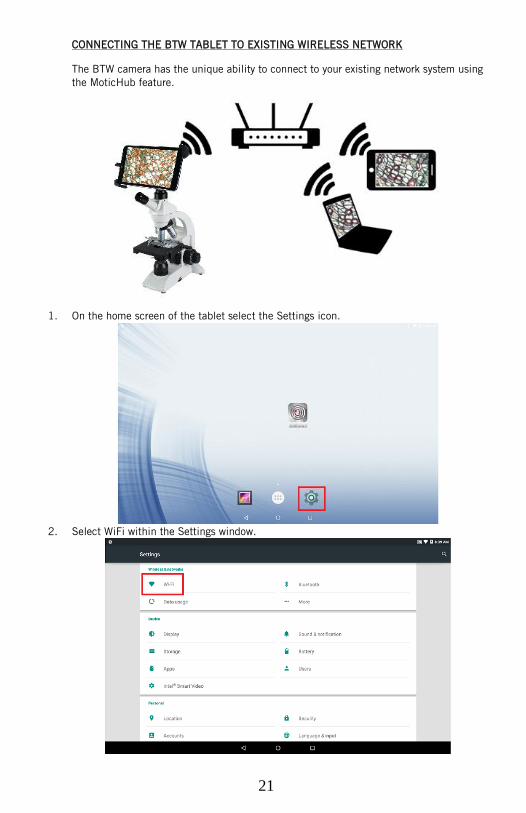
CONNECTING THE BTW TABLET TO EXISTING WIRELESS NETWORK
The BTW camera has the unique ability to connect to your existing network system using
the MoticHub feature.
1. On the home screen of the tablet select the Settings icon.
2. Select WiFi within the Settings window.
22
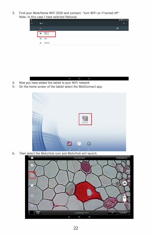
3. Find your Work/Home WiFi SSID and connect. *turn WiFi on if turned off*
Note: In this case I have selected National.
4. Now you have added the tablet to your WiFi network
5. On the home screen of the tablet select the MotiConnect app.
6. Then select the MoticHub icon and MoticHub will launch.
23
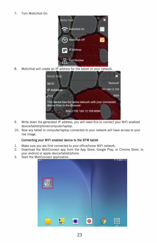
7. Turn MoticHub On.
8. MoticHub will create an IP address for the tablet on your network.
9. Write down the generated IP address, you will need this to connect your WiFi enabled
device/tablet/phone/computer/laptop.
10. Now any tablet or computer/laptop connected to your network will have access to your
live image. Connecting your WiFi enabled device to the BTW tablet
1. Make sure you are first connected to your office/home WiFi network.
2. Download the MotiConnect app from the App Store, Google Play, or Chrome Store, to
your android or apple device/tablet/phone.
3. Start the MotiConnect application.
24
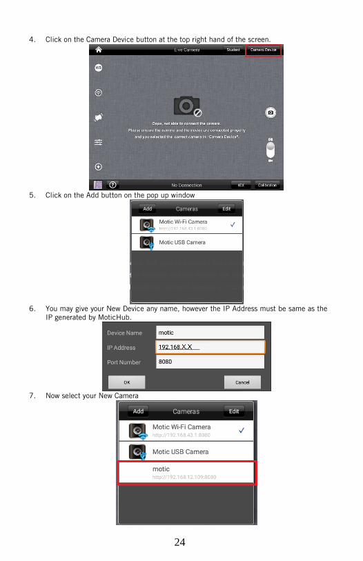
4. Click on the Camera Device button at the top right hand of the screen.
5. Click on the Add button on the pop up window
6. You may give your New Device any name, however the IP Address must be same as the
IP generated by MoticHub.
7. Now select your New Camera
25
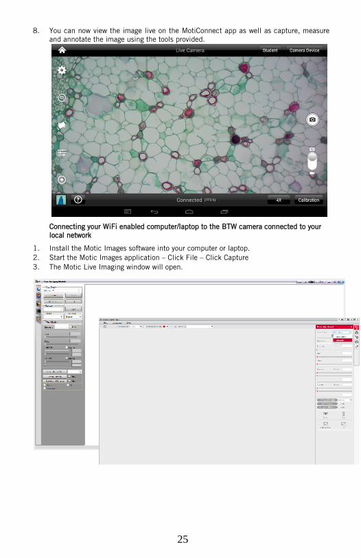
8. You can now view the image live on the MotiConnect app as well as capture, measure
and annotate the image using the tools provided.
Connecting your WiFi enabled computer/laptop to the BTW camera connected to your
local network
1. Install the Motic Images software into your computer or laptop.
2. Start the Motic Images application – Click File – Click Capture
3. The Motic Live Imaging window will open.
26
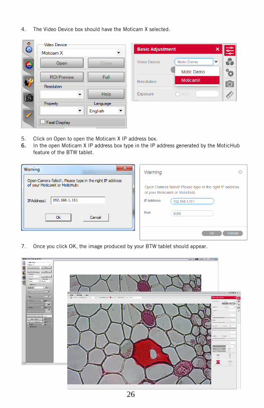
4. The Video Device box should have the Moticam X selected.
5. Click on Open to open the Moticam X IP address box.
6. In the open Moticam X IP address box type in the IP address generated by the MoticHub
feature of the BTW tablet.
7. Once you click OK, the image produced by your BTW tablet should appear.
27
TABLET SOFTWARE
This android tablet comes equipped will all the necessary software needed to start
using your equipment out of the box. Since it is an android tablet, you will be able
to connect to your office/school Wi-Fi network to access the internet and download
additional applications. The primary application for accessing your camera is
MotiConnect T.
MOTICONNECT-T OVERVIEW – HELP MENU
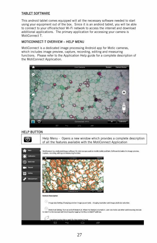
MotiConnect is a dedicated image processing Android app for Motic cameras,
which includes image preview, capture, recording, editing and measuring
functions. Please refer to the Application Help guide for a complete description of
the MotiConnect Application.
HELP BUTTON
Help Menu - Opens a new window which provides a complete description
of all the features available with the MotiConnect Application
28
CALIBRATION – (*Optional – not necessary to use your microscope*)
To prepare for the calibration process, please make sure you have the calibration
slide. The calibration slide has four individual dark round circles. Each dark round
circle corresponds with each objective on your microscope.
The 1.5mm dot (150um – microns) with the 4X objective.
The 0.6mm (600um – microns) with the 10X objective.
The 0.15mm (150um – microns) with the 40x objective.
The 0.07mm (70um – microns) with the 100X objective.
To begin the calibration process, place the calibration on the stage.
1. First place your calibration slide on the stage, switch to the 4X objective,
and move the slide over to the 1.5mm dot.
2. With the dot centered on the tablet screen, select the calibration button,
located on the bottom right hand side of the screen.
3. You should have a bright green circle on the screen.
4. Click the calibration button a second time.
5. This time the calibration settings window will open.
6. In the objective magnification window select the objective you captured
the dot with. In this case the 4X objective.
7. In the diameter window select the diameter of the dot you captured. In
this case the 150um. Then click OK.
8. The last window that will open is the Save Sign window. Since you
capture this image with the 4X objective, it is best to enter this on this
line.
9. The objective line should default to the objective you are calibrating. In
this case it should say 4X.
10. The X and Y numbers on the next two lines should be near identical.
Look at the first three numbers. As long as they are the same within one
or two digits, you have a good calibration.
11. Click Ok and you are done.
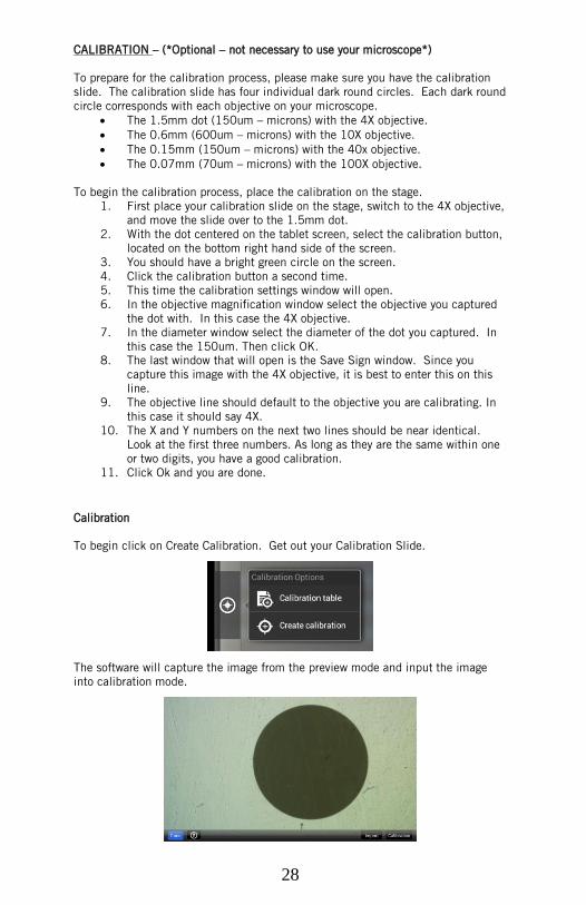
Calibration
To begin click on Create Calibration. Get out your Calibration Slide.
The software will capture the image from the preview mode and input the image
into calibration mode.
29
Now put the Calibration slide on the stage of the microscope and focus the dot in
the center of the screen. For 4x Objective, use the 1.5mm dot. For 10x Objective,
use the 0.6mm dot. For the 40x Objective, use the 0.15mm dot. For the 100x
Objective, use the 0.07mm dot.
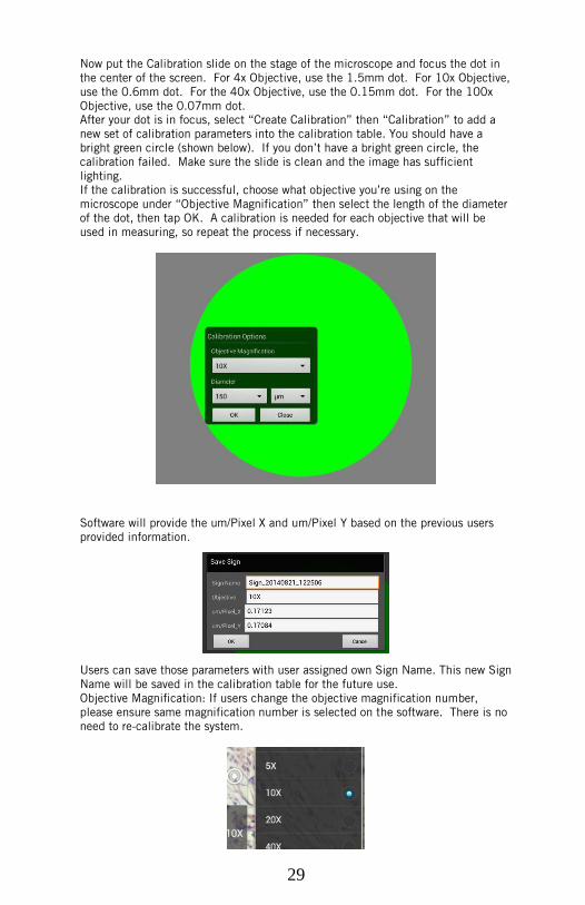
After your dot is in focus, select “Create Calibration” then “Calibration” to add a
new set of calibration parameters into the calibration table. You should have a
bright green circle (shown below). If you don’t have a bright green circle, the
calibration failed. Make sure the slide is clean and the image has sufficient
lighting.
If the calibration is successful, choose what objective you’re using on the
microscope under “Objective Magnification” then select the length of the diameter
of the dot, then tap OK. A calibration is needed for each objective that will be
used in measuring, so repeat the process if necessary.
Software will provide the um/Pixel X and um/Pixel Y based on the previous users
provided information.
Users can save those parameters with user assigned own Sign Name. This new Sign
Name will be saved in the calibration table for the future use.
Objective Magnification: If users change the objective magnification number,
please ensure same magnification number is selected on the software. There is no
need to re-calibrate the system.
30
TRANSFERING IMAGES TO YOUR COMPUTER
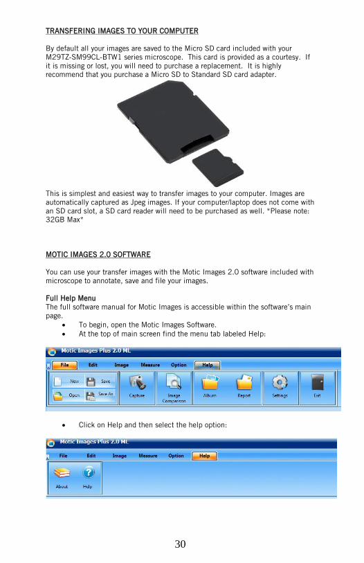
By default all your images are saved to the Micro SD card included with your
M29TZ-SM99CL-BTW1 series microscope. This card is provided as a courtesy. If
it is missing or lost, you will need to purchase a replacement. It is highly
recommend that you purchase a Micro SD to Standard SD card adapter.
This is simplest and easiest way to transfer images to your computer. Images are
automatically captured as Jpeg images. If your computer/laptop does not come with
an SD card slot, a SD card reader will need to be purchased as well. *Please note:
32GB Max*
MOTIC IMAGES 2.0 SOFTWARE
You can use your transfer images with the Motic Images 2.0 software included with
microscope to annotate, save and file your images.
Full Help Menu
The full software manual for Motic Images is accessible within the software’s main
page.
To begin, open the Motic Images Software.
At the top of main screen find the menu tab labeled Help:
Click on Help and then select the help option:
31
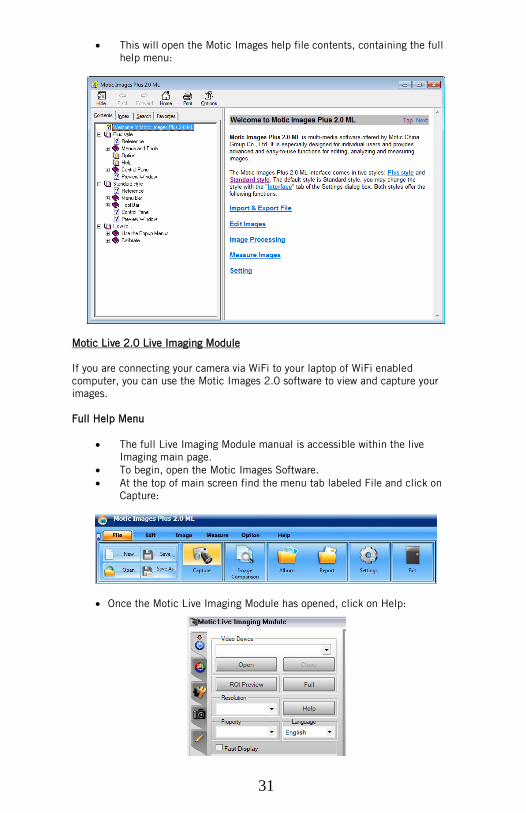
This will open the Motic Images help file contents, containing the full
help menu:
Motic Live 2.0 Live Imaging Module
If you are connecting your camera via WiFi to your laptop of WiFi enabled
computer, you can use the Motic Images 2.0 software to view and capture your
images.
Full Help Menu
The full Live Imaging Module manual is accessible within the live
Imaging main page.
To begin, open the Motic Images Software.
At the top of main screen find the menu tab labeled File and click on
Capture:
Once the Motic Live Imaging Module has opened, click on Help:
32
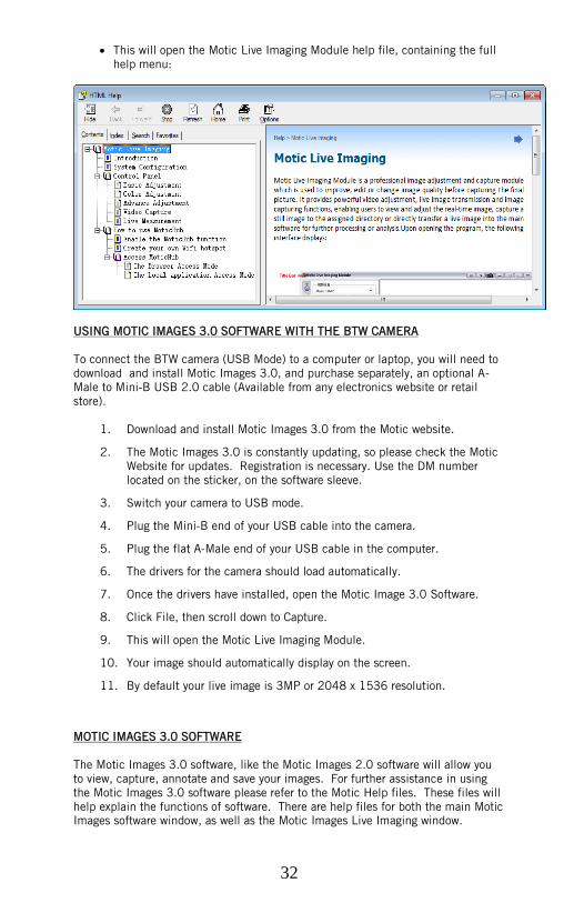
This will open the Motic Live Imaging Module help file, containing the full
help menu:
USING MOTIC IMAGES 3.0 SOFTWARE WITH THE BTW CAMERA
To connect the BTW camera (USB Mode) to a computer or laptop, you will need to
download and install Motic Images 3.0, and purchase separately, an optional A-
Male to Mini-B USB 2.0 cable (Available from any electronics website or retail
store).
1. Download and install Motic Images 3.0 from the Motic website.
2. The Motic Images 3.0 is constantly updating, so please check the Motic
Website for updates. Registration is necessary. Use the DM number
located on the sticker, on the software sleeve.
3. Switch your camera to USB mode.
4. Plug the Mini-B end of your USB cable into the camera.
5. Plug the flat A-Male end of your USB cable in the computer.
6. The drivers for the camera should load automatically.
7. Once the drivers have installed, open the Motic Image 3.0 Software.
8. Click File, then scroll down to Capture.
9. This will open the Motic Live Imaging Module.
10. Your image should automatically display on the screen.
11. By default your live image is 3MP or 2048 x 1536 resolution.
MOTIC IMAGES 3.0 SOFTWARE
The Motic Images 3.0 software, like the Motic Images 2.0 software will allow you
to view, capture, annotate and save your images. For further assistance in using
the Motic Images 3.0 software please refer to the Motic Help files. These files will
help explain the functions of software. There are help files for both the main Motic
Images software window, as well as the Motic Images Live Imaging window.
33
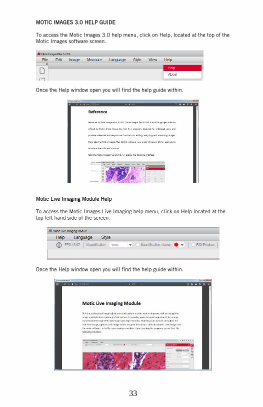
MOTIC IMAGES 3.0 HELP GUIDE
To access the Motic Images 3.0 help menu, click on Help, located at the top of the
Motic Images software screen.
Once the Help window open you will find the help guide within.
Motic Live Imaging Module Help
To access the Motic Images Live Imaging help menu, click on Help located at the
top left hand side of the screen.
Once the Help window open you will find the help guide within.

34
SWIFT OPTICAL INSTRUMENTS, INC. LIMITED LIFETIME WARRANTY
Please see our website, www.swiftoptical.com, for complete warranty
details and exclusions.
Swift Optical Instruments, Inc.● (877) 967-9438
www.swiftoptical.com