Embed Size (px)
Citation preview

SWITCHEDRELUCTANCE
MOTOR DRIVESModeling, Simulation, Analysis,
Design, and Applications
Titles included in the series
Supervised and Unsupervised Pattern Recognition:Feature Extraction and Computational Intelligence
Evangelia Micheli-Tzanakou, Rutgers University
Switched Reluctance Motor Drives: Modeling,Simulation, Analysis, Design, and Applications
R. Krishnan, Virginia Tech
The Power Electronics HandbookTim L. Skvarenina, Purdue University
The Handbook of Applied Computational IntelligenceMary Lou Padgett, Auburn University
Nicolaos B. Karayiannis, University of HoustonLofti A. Zadeh, University of California, Berkeley
The Handbook of Applied NeurocontrolsMary Lou Padgett, Auburn University
Charles C. Jorgensen, NASA Ames Research CenterPaul Werbos, National Science Foundation
I n d u s t r i a l E l e c t r o n i c s S e r i e sSeries Editor
J. David Irwin, Auburn University
SWITCHEDRELUCTANCE
MOTOR DRIVES
R. Krishnan — Fellow, IEEEThe Bradley Department of Electrical and Computer Engineering
Fellow, Center for Organizational and Technological Advancement (COTA)Virginia Tech, Blacksburg, Virginia
Boca Raton London New York Washington, D.C.CRC Press
Modeling, Simulation, Analysis,Design, and Applications
I n d u s t r i a l E l e c t r o n i c s S e r i e s
This book contains information obtained from authentic and highly regarded sources. Reprinted materialis quoted with permission, and sources are indicated. A wide variety of references are listed. Reasonableefforts have been made to publish reliable data and information, but the author and the publisher cannotassume responsibility for the validity of all materials or for the consequences of their use.
Neither this book nor any part may be reproduced or transmitted in any form or by any means, electronicor mechanical, including photocopying, microfilming, and recording, or by any information storage orretrieval system, without prior permission in writing from the publisher.
Direct all inquiries to CRC Press LLC, 2000 N.W. Corporate Blvd., Boca Raton, Florida 33431.
Trademark Notice:
Product or corporate names may be trademarks or registered trademarks, and areused only for identification and explanation, without intent to infringe.
Visit the CRC Press Web site at www.crcpress.com
© 2001 by CRC Press LLC
No claim to original U.S. Government worksInternational Standard Book Number 0-8493-0838-0
Library of Congress Card Number 2001025727Printed in the United States of America 1 2 3 4 5 6 7 8 9 0
Printed on acid-free paper
Library of Congress Cataloging-in-Publication Data
Ramu, Krishnan.Switched reluctance motor drives: modeling, simulation, analysis, design, andapplications / Krishnan Ramu.
p. cm.—(Industrial electronics series)Includes bibliographical references and index.ISBN 0-8493-0838-0 (alk. paper)1. Reluctance motors. I. Title. II. Series.
TK2787 .R35 2001621.46—dc21 2001025727
0838_Frame_FM.fm Page iv Monday, May 21, 2001 6:47 AM

ForMadhivanan and Ilankeeran
0838_Frame_FM.fm Page v Monday, May 21, 2001 6:47 AM
Preface
Industrial interest in switched reluctance motor (SRM) drives has varied since 1850s.The recent surge of activity since the 1980s has spurred university and industrialresearch and product development in the U.K. and U.S. and in a very small measurein some other countries. This interest has been primarily due to the emerging marketsfor variable speed drives in consumer and industrial products, such as home appli-ances, air conditioning, hand tools, fans, pump motor drives, extruders, and auto-motive and railway accessory drives. These new applications for variable speed drivesare very cost sensitive while demanding higher reliability and an equivalent perfor-mance of dc and induction motor drives at the minimum. SRM drive systemspromise to meet such demands in some select high-volume applications, hence thespurt of activity in this field. The expansion of knowledge in this field has beengreat, and it is timely to summarize in this book some of the key results in modeling,simulation, analysis, and design procedures for SRMs; their converter topologies;system integration; control techniques with and without position sensors; the muchtalked-about noise issue; and, finally, their applications. With that perspective, thisbook has been in preparation for the last 12 years, and the material has been taughtin a number of IEEE forums, at industrial sites, and at the graduate level at theauthor’s university and at Padova University in Italy.
The book presumes a familiarity with fundamentals of electromechanics, intro-ductory power electronics, and linear control system theory, all at the undergraduatelevel. The intended audience for the book is electrical engineers in industrial andfederal laboratories and students at the senior/graduate level in universities. Tradi-tional trappings of worked examples and exercise problems are done away with, asthis subject demands complete immersion and therefore much more intensive studyand initiative to do extensive work by the readers on their own. The book is organizedas follows.
Chapter 1 contains the introduction to SRM, its principle of operation, varioustypes of SRM configurations including linear SRM, and the equivalent circuit.Chapter 2 discusses the magnetic equivalent circuit derivation and an analyticalapproach to the evaluation of the key three-dimensional relationships among fluxlinkages, excitation current, and rotor position in the SRM. The nonlinear materialcharacteristics are preserved in this approach. These machine characteristics arecentral to the analysis and design of SRMs.
Chapter 3 contains an analytical design procedure for the SRM based on theoutput power equation that is prevalent in the design of electrical machines. Theresistive and core losses for thermal consideration, criteria for the selection of statorand rotor back iron thickness, pole height, number of phases, ratio of pole arc topole pitch, self-starting requirements to be fulfilled in the design, inductance mea-surement, and design of linear SRM from an equivalent rotary SRM are addressed
0838_Frame_FM.fm Page vii Monday, May 21, 2001 6:47 AM
from fundamentals. Steady-state computation of air gap torque is also derived inthis chapter.
Converters and their classification, principle of operation, design considerations,and merits and demerits of each converter and their impact on the machine outputform the core of Chapter 4. Converters that have some merit from the point of viewof industrial applications are considered in this selection.
The converter, SRM, and load are integrated through a controller. The basic drivesystem control is developed and illustrated with an implementation to demonstratethe similarity of this drive to dc and ac drives. The inadequacy of such controllersfor high-performance applications is discussed, and contributing factors are identi-fied. The heart of a high-performance system is current control, and various methodsof current control such as the conventional linearized controller, linearizing anddecoupling controller, and hybrid controller are systematically derived and devel-oped. An alternative to current control is the flux linkages control, and its merits anddemerits are discussed. The torque controller to produce very little torque rippleusing torque distribution function-based control is introduced and its performance isstudied in detail. Finally, analytic derivations of the speed controller gain and timeconstants are made using the symmetric optimum method. Throughout this chapter,an analytical approach is emphasized to understand the relationship between machineparameters and output variables. Usually the literature neglects mutual coupling inperformance prediction. It is shown in the text that its omission may lead to as muchas 6% torque ripple even in very good machine designs. Methods to include mutualcoupling effects in performance prediction and in the linearized and decoupledcurrent controller, flux linkage controller, and torque controller designs are presented.
Dynamic modeling, simulation, and analysis play crucial roles in the drivesystem analysis and design and are considered in Chapter 6. The subsystems mod-eling and their integration are developed step by step. The simulation procedure isillustrated with results to enhance the understanding of the SRM drive.
The SRM drive has been plagued with the acoustic noise problem. To understandthis issue, the sources of acoustic noise are explained in Chapter 7. Measures tomitigate noise from magnetic, mechanical, aerodynamic, and electronic sources arepresented. Active noise cancellation techniques using the power converter controlare also described. A brief summary of qualitative measures to reduce noise is given.In order to facilitate noise quantification in laboratories, an introduction to measure-ment is included in this chapter.
The necessity for absolute rotor position information in SRM drives increasesthe complexity of motor manufacture, with the mounting of position sensors resultingin higher costs compared to other drives that do not require rotor position sensorsfor their operation, such as dc and ac motor drives. Various electronic methods forestimating or predicting the rotor position information are discussed along with theiralgorithms in Chapter 8. These methods are not invasive mechanically and use only thevoltage applied across the winding and the current flowing in it. Many of the methodsdiscussed in the literature are classified and their implementations are discussed toenable readers to assess the suitability of a particular method in the context of anapplication. Low-cost current sensing to obtain a completely sensorless SRM drivesystem is also included.
0838_Frame_FM.fm Page viii Monday, May 21, 2001 6:47 AM
Application considerations and particular applications of the SRM drive systemsare described in Chapter 9. The SRM drive system is reviewed for merits and demeritsin regard to each of its subsystems. By doing so, the strengths and weaknesses of theSRM drive become apparent and hence their suitability for a given application. Appli-cations are discussed in terms of the power categories of low, medium, and high andhigh-speed drives. Emerging applications in the high-volume, underwater, and linear-drive areas, particularly in machine tool drives, are identified.
This book contains significant results from my research students, past and present.They are Prof. R. Arumugam, Dr. Peter Materu, Dr. Guen-Hie Rim, Dr. AravindBharadwaj, Mr. A. Bedingfield, Mr. Prasad Ramakrishna, Mr. Terry Jackson, Dr. H. K.Bae, Dr. B. S. Lee, Dr. Praveen Vijayraghavan, Mr. Phil Vallance, and Ms. AmandaStaley. They have permitted me to draw generously from their theses. Parts ofChapters 1 and 3 are from Dr. Lee’s thesis, parts of Chapters 5 and 6 are fromDr. Bae’s thesis, part of Chapter 5 is from Mr. Jackson’s thesis, and part of Chapter 2is from Dr. Vijayraghavan’s thesis. To them, I owe my gratitude. When there washardly any interest in this subject matter nearly two decades back, my mentorDr. J. F. Lindsay encouraged me to pursue this research topic. I am very grateful tohim for his advice and insight. Initial funding from A. O. Smith Corp., WhirlpoolCorp., and Black & Decker Corp. to initiate SRM research is gratefully acknowl-edged. Portions of this book were written while the author was on sabbatical inINPG, France, at the kind invitation of Prof. Jean Claude Sabonnadiere. I thank himfor it. Earlier versions of this text have been taught at the University of Padova atthe invitation of Prof. S. Bolognani, and I am grateful for his hospitality. Mydepartment provided excellent facilities to carry on the work related to this text. Iam grateful for this to Profs. F. W. Stephenson, the Dean of Engineering, and L. A.Ferrari, Vice Provost for Special Initiatives. Monique Johnson helped me in alleditorial work and with correcting part of the manuscript and her help is gratefullyacknowledged. This manuscript preparation was partially supported by the Centerfor Organizational and Technological Advancement (COTA) at Virginia Tech in theform of a fellowship. For that I am grateful to Prof. Gregg Boardman, the center’sdirector.
My sincere thanks to all at CRC Press who interacted with me during advancemarketing for their time and help. I am also grateful to the project editor, Ms. SamarHaddad, for making amazing progress with the manuscript in a record time and forsmoothing out the rough edges. Her patience made possible an enjoyable andwonderful journey through various steps in production.
The patience and gentle prodding of Nora Konopka, my editor, helped to main-tain my focus on the book in the last year. It has been very enjoyable working withher on this book, and I am very grateful to her for the talented team that she assembledto make this book possible.
I owe immense gratitude to my wife, Vijaya, for her cheer and encouragementthroughout this endeavor.
R. Krishnan
0838_Frame_FM.fm Page ix Monday, May 21, 2001 6:47 AM
About the Author
R. Krishnan
received his Ph.D. in electrical engineering from Concordia University,Montreal, Canada, in 1982. He started his teaching career with the University ofMadras in 1972. He was a staff engineer and then principal engineer at GouldResearch Center from 1982 to 1985, and since then he has been with Virginia Tech.He is a professor of electrical and computer engineering, and his research interestsinclude electric motor drives and applied control. He has developed many proprietarymotor drives, an electronic stunner, uninterruptible power supplies, converters forPM brushless dc, switched reluctance and induction motor drives, controllers for acand switched reluctance motor drives, and personal medical monitors. Some are inindustrial use and others are under consideration for market.
Dr. Krishnan has organized and conducted short courses on vector-controlledinduction motor drives, PM synchronous and brushless dc motor drives, and switchedreluctance motor drives in the U.S., France, Italy, Korea, and Denmark. He is theauthor of
Electric Motor Drives
(Prentice-Hall, 2001).He is a Fellow of the Institute of Electrical and Electronic Engineers (IEEE),
cited for his contributions to the development of ac and switched reluctance motordrives. He is also a Fellow of the Center for Organizational & TechnologicalAdvancement (COTA) at Virginia Tech. He is the director of the Center for RapidTransit Systems (CRTS), pursuing unique, safe, high-speed, energy-efficient, andpersonal electric transit solutions and their implementations in the U.S.
0838_Frame_FM.fm Page xi Monday, May 21, 2001 6:47 AM
Contents
Chapter 1
Principle of Operation of the Switched Reluctance Motor
1.1 Introduction1.2 Background1.3 Elementary Operation of the Switched Reluctance Motor1.4 Principle of Operation of the Switched Reluctance Motor1.5 Derivation of the Relationship between Inductance
and Rotor Position 1.6 Equivalent Circuit1.7 SRM Configurations
1.7.1 Rotary SRM1.7.2 Single-Phase SRM
1.8 Linear Switched Reluctance Machines1.8.1 Introduction1.8.2 Machine Topology and Elementary Operation
of LSRMsReferences
Chapter 2
Steady-State Performance and Analytic Derivationof SRM Characteristics
2.1 Introduction2.2 Data for Performance Computation2.3 Analytic Method for the Computation of Motor Flux
Linkages2.3.1 Method of Inductance Calculation
2.3.1.1 Flux Density Evaluation2.3.1.2 mmf Evaluation2.3.1.3 Calculation of Reluctance2.3.1.4 Assumptions
2.3.2 Unaligned Inductance2.3.2.1 Flux Path 1
2.3.2.1.1 Rotor Back Iron2.3.2.1.2 Stator Pole 2.3.2.1.3 Stator Back Iron
2.3.2.2 Flux Path 22.3.2.2.1 Air Gap2.3.2.2.2 Stator Pole 2.3.2.2.3 Rotor Pole2.3.2.2.4 Rotor Back Iron2.3.2.2.5 Stator Back Iron
0838_Frame_FM.fm Page xiii Monday, May 21, 2001 6:47 AM
2.3.2.3 Flux Path 3 2.3.2.3.1 Air Gap2.3.2.3.2 Stator Pole2.3.2.3.3 Rotor Pole2.3.2.3.4 Rotor Back Iron2.3.2.3.5 Stator Back Iron
2.3.2.4 Flux Path 42.3.2.4.1 Air Gap2.3.2.4.2 Stator Pole2.3.2.4.3 Rotor Pole2.3.2.4.4 Rotor Back Iron2.3.2.4.5 Stator Back Iron
2.3.2.5 Flux Path 52.3.2.5.1 Air Gap2.3.2.5.2 Stator Pole2.3.2.5.3 Rotor Pole2.3.2.5.4 Rotor Back Iron2.3.2.5.5 Stator Back Iron
2.3.2.6 Flux Path 62.3.2.6.1 Air Gap2.3.2.6.2 Stator Pole 2.3.2.6.3 Stator Back Iron2.3.2.6.4 Magnetic Equivalent Circuit
2.3.2.7 Flux Path 72.3.2.7.1 Unaligned Inductance
2.3.3 Aligned Inductance2.3.3.1 Flux Path 12.3.3.2 Flux Path 7
2.3.4 Results and Comparison2.3.5 Performance Evaluation2.3.6 Inductances at Intermediate Positions
2.3.6.1 Region 12.3.6.1.1 Flux Path 12.3.6.1.2 Flux Path 2 2.3.6.1.3 Flux Path 3 2.3.6.1.4 Flux Path 42.3.6.1.5 Flux Path 52.3.6.1.6 Flux Path 6 2.3.6.1.7 Inductance in Region 1
2.3.6.2 Region 22.3.6.2.1 Flux Path 12.3.6.2.2 Flux Path 22.3.6.2.3 Flux Path 3 2.3.6.2.4 Flux Path 4 2.3.6.2.5 Flux Path 5 2.3.6.2.6 Inductance Evaluation
0838_Frame_FM.fm Page xiv Monday, May 21, 2001 6:47 AM
2.4 Secondary Flux Paths2.5 Computation of InductanceReferences
Chapter 3
Design of SRM
3.1 Introduction3.2 Derivation of Output Equation3.3 Selection of Dimensions
3.3.1 Diameter and Length3.3.2 Number of Turns3.3.3 Thermal Consideration
3.3.3.1 Stator Copper Losses3.3.3.2 Approximate Evaluation of
T
r
3.3.3.3 Approximate Evaluation of
T
f
3.3.4 Stator Back Iron Thickness3.3.5 Stator Coil Dimensions3.3.6 Stator Pole Height3.3.7 Outer Diameter of Stator Lamination3.3.8 Rotor Back Iron Thickness3.3.9 Rotor Pole Height 3.3.10 Estimation of Core Losses3.3.11 Flux Density Waveforms
3.3.11.1 Stator3.3.11.2 Rotor 3.3.11.3 Core Losses3.3.11.4 Calculation Procedure
3.4 Design Verification3.5 Operational Limit3.6 Selection of Number of Phases 3.7 Selection of Poles3.8 Ratio of Pole Arc to Pole Pitch3.9 Selection of Pole Arcs
3.9.1 Minimum Rotor and Stator Pole Arcs to Achieve Self-Starting
3.9.2 Overlap Angle (
θ
0
) Limits3.9.3 Upper Limit on
β
r
3.9.4 Computation of Turn-Off Angle3.9.5 Selection of Pole Base
3.10 Effect of Air Gap on Torque3.11 Measurement of Inductance3.12 Calculation of Torque
3.12.1 Average Torque3.12.2 Instantaneous Torque
3.13 Design of the Linear Switched Reluctance Machine3.13.1 Introduction
0838_Frame_FM.fm Page xv Monday, May 21, 2001 6:47 AM
3.13.2 LSRM Configurations3.13.2.1 Three-Phase LSRM with Active Stator
and Passive Translator Structure 3.13.2.2 Four-Phase LSRM with Active Translator and Passive
Stator Structure3.13.3 LSRM Design
3.13.3.1 Specifications of the LSRM3.13.3.2 Design of Rotary SRM3.13.3.3 Conversion of RSRM Dimensions
to LSRM Dimensions3.13.3.4 Example 1: Design of Three-Phase LSRM with Active
Stator and Passive Translator 3.13.3.5 Example 2: Four-Phase LSRM Prototype with Active
Translator and Passive Stator3.13.4 Design Verification
3.13.4.1 Analytical Inductance Calculation3.13.4.1.1 Aligned Inductance Calculation3.13.4.1.2 Intermediate Inductance Calculation—
One-Third Shift of Translator from Fully Aligned Position
3.13.4.1.3 Intermediate Inductance Calculation—Two-Thirds Shifting of Translator fromFully Aligned Position
3.13.4.1.4 Fully Unaligned InductanceCalculation
3.13.4.2 Analytical Force Calculation 3.13.4.3 Finite Element Analysis Verification 3.13.4.4 Experimental Setup for Measurements
3.13.4.4.1 Inductance Measurement 3.13.4.4.2 Force Measurement
3.13.4.5 Results and ComparisonAppendix 3A: Calculation of Air gap Permeance
Parallelepiped Semicircular Cylinder Half Annulus Spherical Quadrant Spherical Shell Quadrant Total Permeance Value of the Air gap Flux Paths
Appendix 3B: Flux Paths and Associated Variablesin the Stator and Translator Aligned Position Region
MMF per Path Mean Path Length and Mean Cross-Section Area
Intermediate Position Region I MMF Per Path Mean Path Length and Mean Cross-Section Area
0838_Frame_FM.fm Page xvi Monday, May 21, 2001 6:47 AM
Intermediate Position Region II MMF per Path Mean Path Length and Mean Cross-Section Area
Unaligned Position Region MMF per Path Mean Path Length and Mean Cross-Section Area
References
Chapter 4
Converters for SRM Drives
4.1 Converter Configurations4.1.1 Asymmetric Bridge Converter
4.1.1.1 Switching Strategy4.1.1.2 Device Ratings4.1.1.3 Switch rms Current4.1.1.4 Diode Average Current4.1.1.5 Selection of Device Current Ratings
4.1.2 Asymmetric Converter Variation 4.1.3 Energy Recovery Snubber
4.2 Single-Switch-per-Phase Converters4.2.1 R-Dump
4.2.1.1 Device Current Ratings 4.2.1.2 Switch Current4.2.1.3 Diode Current 4.2.1.4 Power Rating of Dump Resistor
4.2.2 Bifilar Type4.2.3 Split dc Supply Converter4.2.4
q
Switches and 2
q
Diodes4.2.5
q
Switch and 2
q
Diode Configurationwith Independent Phase Current Control
4.3 (
q
+
1) Switch and Diode Configurations 4.3.1 Configuration with Equal Sharing4.3.2 C-Dump Converter
4.3.2.1 Modes of Operation and Mode Equations4.3.2.1.1 Mode 1:
T
1
On and
T
r
Off4.3.2.1.2 Modes 2 and 3:
T
1
and
T
r
BothOn and Then Off
4.3.2.1.3 Mode 4: Phase Current Commutation4.3.2.1.4 Mode 5:
T
1
Off,
T
r
On4.3.2.2 Design Procedure
4.3.2.2.1 Device Ratings4.3.2.2.2 Dump Capacitor Rating4.3.2.2.3 Incremental Current in Machine Phases4.3.2.2.4 Switching Frequency4.3.2.2.5 Rating of
L
r
4.3.2.2.6 Recovery Current
0838_Frame_FM.fm Page xvii Monday, May 21, 2001 6:47 AM
4.3.2.2.7 Voltage and Current Control in EnergyRecovery Circuits
4.3.3 C-Dump with Freewheeling4.3.4 One Common Switch Configuration 4.3.5 Minimum Switch Topology with Variable dc Link
4.3.5.1 Operational Modes of the Converter Circuit4.3.5.2 Design Considerations of the Chopper
Circuit Components4.3.5.3 Performance Constraints and Design
of the Converter4.3.5.3.1 Current Commutation Time 4.3.5.3.2 Voltage Rise in the dc Source Capacitor4.3.5.3.3 Results and Analysis
4.3.5.4 Merits and Demerits of the Converter4.3.5.5 Variable dc Link Voltage with Buck-Boost
Converter Topology4.3.6 (1.5
q
) Switches and Diodes Configuration 4.4 Comparison of Some Power Converters 4.5 Two-Stage Power Converter
4.5.1 Front-End Converter 4.5.2 Machine-Side Converter4.5.3 Operation of the Scheme
4.6 Resonant Converter CircuitsReferences
Chapter 5
Control of SRM Drive
5.1 Introduction5.2 Control Principle5.3 Closed-Loop, Speed-Controlled SRM Drive
5.3.1 Design Example5.3.2 Solution 5.3.3 Current Loop5.3.4 Current Comparator5.3.5 Carrier Signal5.3.6 Incorporation of Rotor Position Information5.3.7 Speed Loop
5.4 Design of Current Controllers 5.4.1 Voltage and Torque Equations for the SRM 5.4.2 Derivation of the SRM Small-Signal Model5.4.3 System Block Diagram5.4.4 Design of Current Controller
5.4.4.1 Example 1: 5-hp SRM Drive System 5.4.4.2 Current Controller Design5.4.4.3 Nonlinear Dynamic Simulation
of Current Loop
0838_Frame_FM.fm Page xviii Monday, May 21, 2001 6:47 AM
5.4.5 Linearized Decoupling Current Controller NeglectingMutual Inductance
5.4.6 Design of Current Controller Including MutualCoupling Effects
5.5 Flux Linkage Controller5.5.1 Machine without Mutual Coupling
5.6 Torque Control5.6.1 Methods of Torque Control
5.6.1.1 Torque Distribution Neglecting MutualInductance and Saturation
5.6.1.2 Torque Distribution Including MutualInductance and Neglecting Saturation
5.6.1.3 Torque Distribution Including MutualInductance and Saturation
5.6.2 Simulation Results 5.6.3 Implementation of Torque Controller
5.7 Design of the Speed Controller5.7.1 Features of the Symmetric Optimum Function5.7.2 Simulation Results
References
Chapter 6
Modeling and Simulation of the SRMDrive System
6.1 Introduction6.2 Modeling
6.2.1 Machine Model 6.2.1.1 Per Phase Model6.2.1.2 Representation of Machine Magnetic
Characteristics6.2.1.3 Method 16.2.1.4 Method 26.2.1.5 Torque Representation and Its Computation6.2.1.6 Mutual Inductance
6.2.2 Converter6.2.2.1 Effect of Source Impedance and dc Link Filter 6.2.2.2 Device-Transient Model
6.2.3 Load6.2.4 Controller
6.2.4.1 Speed Controller6.2.4.2 Torque Controller6.2.4.3 Current Command Controller6.2.4.4 Current Controller
6.2.4.4.1 PWM Current Controller6.2.4.4.2 Hysteresis Current Controller
0838_Frame_FM.fm Page xix Monday, May 21, 2001 6:47 AM
6.3 Simulation6.3.1 Simulation Results
References
Chapter 7
Acoustic Noise and Its Control in SRMs
7.1 Introduction7.2 Sources of Acoustic Noise in Electrical Machines
7.2.1 Noise Sources7.2.1.1 Magnetic Sources of Noise7.2.1.2 Mechanical Sources of Noise
7.2.1.2.1 Self7.2.1.2.2 Load-Induced7.2.1.2.3 Auxiliaries7.2.1.2.4 Rotor Unbalance
7.2.1.3 Aerodynamic Sources of Noise7.2.1.4 Electronic Sources of Noise
7.3 Noise Mitigation 7.3.1 Magnetic Noise Mitigation7.3.2 Mechanical Noise Mitigation7.3.3 Aerodynamic Noise Mitigation7.3.4 Electronic Noise Mitigation7.3.5 Active Noise-Cancellation Techniques
7.3.5.1 Two-Stage Commutation Method 7.3.5.2 Voltage-Smoothing Method 7.3.5.3 Three-Stage Commutation Method7.3.5.4 Extended Freewheeling Method7.3.5.5 Disadvantages of Noise-Cancellation Techniques
7.4 Qualitative Design Measures to Reduce Noise7.4.1 Machine Design Considerations7.4.2 Torque-Smoothing Control7.4.3 Converters with a High Degree of Freedom7.4.4 Varying Input Voltage
7.5 Measurement of Acoustic Noise and Vibrations7.6 Future DirectionsAppendix 7A: Derivation of First-Mode Frequency of an SRM
Potential EnergyKinetic Energy Natural Frequency
References
Chapter 8
Sensorless Operation of SRM Drives
8.1 Introduction8.2 Current Sensing
8.2.1 Current-Sensing Methods
0838_Frame_FM.fm Page xx Monday, May 21, 2001 6:47 AM
8.2.2 Current Sensing with Resistors8.2.3 Drive Scheme with Current Limiter
8.3 Rotor Position Measurement and Estimation Methods8.3.1 Sensor-Based Measurement
8.4 Sensorless Rotor Position Estimation8.4.1 Inductance-Based Estimation
8.4.1.1 Incremental Inductance Measurement8.4.1.1.1 Current Rise Time Method8.4.1.1.2 Current Fall Time Method
8.4.1.2 Sensing with Inactive Phases 8.4.1.3 Estimation Based on Constant
Current/Flux Linkages8.4.1.4 Resonant Circuit Method8.4.1.5 Synchronous Demodulation Method8.4.1.6 Variation of the Demodulation Method8.4.1.7 Mutual Flux Linkages Method
8.4.2 Direct Inductance-Sensing Methods8.4.2.1 Current Gradient Method 8.4.2.2 Flux Linkages Estimation Method Based
on Reference Position8.4.2.3 Flux-Linkages-Based Method with
Hesitation-Free Starting8.4.3 Observer-Based Rotor Position Estimation8.4.4 Intelligent-Control-Based Estimation
8.4.4.1 Artificial Neural Networks8.4.4.2 Fuzzy Control Estimator
8.4.5 Sensing Coil Approach References
Chapter 9
Application Considerations and Applications
9.1 Introduction9.2 Review of SRM Drive Features for Application Consideration
9.2.1 Motor9.2.1.1 Advantages9.2.1.2 Disadvantages
9.2.2 Converter9.2.2.1 Advantages9.2.2.2 Disadvantages
9.2.3 Control9.3 Applications
9.3.1 Low-Power Drives 9.3.2 Medium-Power Drives9.3.3 High-Power Drives9.3.4 High-Speed Drives
0838_Frame_FM.fm Page xxi Monday, May 21, 2001 6:47 AM

9.4 Emerging Applications9.4.1 High-Volume Applications9.4.2 Underwater Applications9.4.3 Linear Drive Applications
References
0838_Frame_FM.fm Page xxii Monday, May 21, 2001 6:47 AM
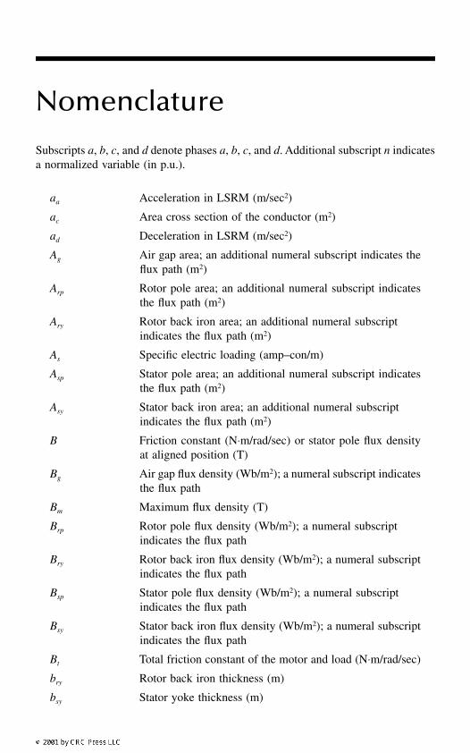
Nomenclature
Subscripts
a
,
b
,
c
, and
d
denote phases
a
,
b
,
c
, and
d
. Additional subscript
n
indicatesa normalized variable (in p.u.).
a
a
Acceleration in LSRM (m/sec
2
)
a
c
Area cross section of the conductor (m
2
)
a
d
Deceleration in LSRM (m/sec
2
)
A
g
Air gap area; an additional numeral subscript indicates theflux path (m
2
)
A
rp
Rotor pole area; an additional numeral subscript indicatesthe flux path (m
2
)
A
ry
Rotor back iron area; an additional numeral subscriptindicates the flux path (m
2
)
A
s
Specific electric loading (amp–con/m)
A
sp
Stator pole area; an additional numeral subscript indicatesthe flux path (m
2
)
A
sy
Stator back iron area; an additional numeral subscriptindicates the flux path (m
2
)
B
Friction constant (N
⋅
m/rad/sec) or stator pole flux densityat aligned position (T)
B
g
Air gap flux density (Wb/m
2
); a numeral subscript indicatesthe flux path
B
m
Maximum flux density (T)
B
rp
Rotor pole flux density (Wb/m
2
); a numeral subscript indicates the flux path
B
ry
Rotor back iron flux density (Wb/m
2
); a numeral subscriptindicates the flux path
B
sp
Stator pole flux density (Wb/m
2
); a numeral subscript indicates the flux path
B
sy
Stator back iron flux density (Wb/m
2
); a numeral subscriptindicates the flux path
B
t
Total friction constant of the motor and load (N
⋅
m/rad/sec)
b
ry
Rotor back iron thickness (m)
b
sy
Stator yoke thickness (m)
0838_Frame_FM.fm Page xxiii Monday, May 21, 2001 6:47 AM
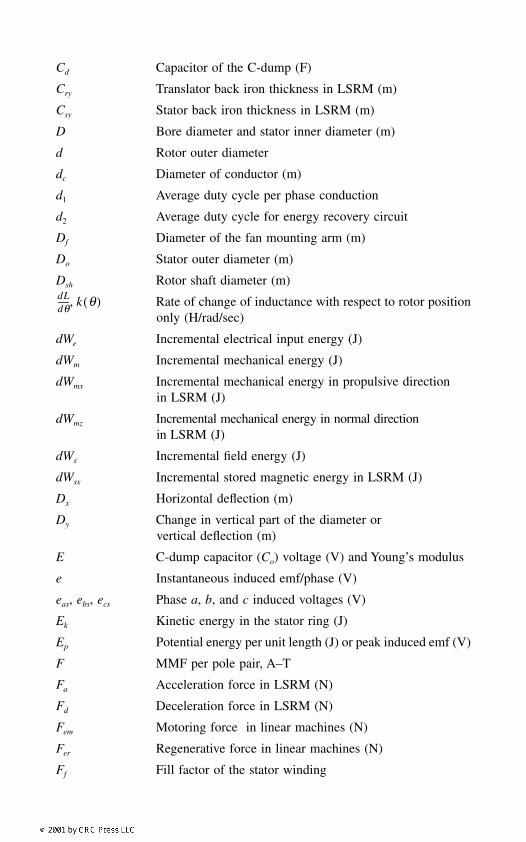
C
d
Capacitor of the C-dump (F)
C
ry
Translator back iron thickness in LSRM (m)
C
sy
Stator back iron thickness in LSRM (m)
D
Bore diameter and stator inner diameter (m)
d
Rotor outer diameter
d
c
Diameter of conductor (m)
d
1
Average duty cycle per phase conduction
d
2
Average duty cycle for energy recovery circuit
D
f
Diameter of the fan mounting arm (m)
D
o
Stator outer diameter (m)
D
sh
Rotor shaft diameter (m)
Rate of change of inductance with respect to rotor positiononly (H/rad/sec)
dW
e
Incremental electrical input energy (J)
dW
m
Incremental mechanical energy (J)
dW
mx
Incremental mechanical energy in propulsive direction in LSRM (J)
dW
mz
Incremental mechanical energy in normal direction in LSRM (J)
dW
s
Incremental field energy (J)
dWsx Incremental stored magnetic energy in LSRM (J)
Dx Horizontal deflection (m)
Dy Change in vertical part of the diameter or vertical deflection (m)
E C-dump capacitor (Co) voltage (V) and Young’s modulus
e Instantaneous induced emf/phase (V)
eas, ebs, ecs Phase a, b, and c induced voltages (V)
Ek Kinetic energy in the stator ring (J)
Ep Potential energy per unit length (J) or peak induced emf (V)
F MMF per pole pair, A–T
Fa Acceleration force in LSRM (N)
Fd Deceleration force in LSRM (N)
Fem Motoring force in linear machines (N)
Fer Regenerative force in linear machines (N)
Ff Fill factor of the stator winding
dLdθ------ k θ( ),
0838_Frame_FM.fm Page xxiv Monday, May 21, 2001 6:47 AM
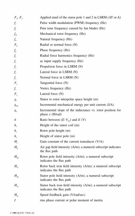
F1, F2 Applied mmf of the stator pole 1 and 2 in LSRM (AT or A)
fc Pulse width modulation (PWM) frequency (Hz)
ff Pure tone frequency caused by fan blades (Hz)
fm Mechanical rotor frequency (Hz)
fn Natural frequency (Hz)
Fn Radial or normal force (N)
fp Phase frequency (Hz)
fr Radial force harmonics frequency (Hz)
fs ac input supply frequency (Hz)
fx Propulsion force in LSRM (N)
fy Lateral force in LSRM (N)
fz Normal force in LSRM (N)
Ft Tangential force (N)
fv Vortex frequency (Hz)
Fy Lateral force (N)
gi Stator to rotor interpolar space height (m)
gmi Incremental mechanical energy per unit current (J/A)
gx Incremental slope of the inductance vs. rotor position forphase x (H/rad)
h Ratio between (E–Vdc) and E (V)
hc Height of the stator coil (m)
hr Rotor pole height (m)
hs Height of stator pole (m)
Hc Gain constant of the current transducer (V/A)
Hg Air gap field intensity (A/m); a numeral subscript indicatesthe flux path
Hrp Rotor pole field intensity (A/m); a numeral subscript indicates the flux path
Hry Rotor back iron field intensity (A/m); a numeral subscriptindicates the flux path
Hsp Stator pole field intensity (A/m); a numeral subscript indicates the flux path
Hsy Stator back iron field intensity (A/m); a numeral subscriptindicates the flux path
H Speed feedback gain (V/rad/sec)
I rms phase current or polar moment of inertia
0838_Frame_FM.fm Page xxv Monday, May 21, 2001 6:47 AM
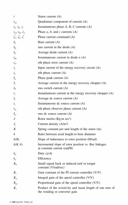
i Stator current (A)
i1q Quadrature component of current (A)
ia, ib, ic Instantaneous phase A, B, C currents (A)
ias, ibs, ics Phase a, b, and c currents (A)
Phase current command (A)
Ib Base current (A)
ID rms current in the diode (A)
Id Average diode current (A)
idn Instantaneous current in diode n (A)
ien nth phase error current (A)
ii Input current of the energy recovery circuit (A)
in nth phase current (A)
Ip Phase peak current (A)
Ir Average current in the energy recovery chopper (A)
IT rms switch current (A)
ir Instantaneous current in the energy recovery chopper (A)
Is Average dc source current (A)
is Instantaneous dc source current (A)
isn nth phase observer phase current (A)
Isr rms dc source current (A)
J Rotor inertia (Kg·m sec2)
Jc Current density (A/m2)
K Spring constant per unit length of the stator (m)
k Ratio between axial length to bore diameter
k(θ) Slope of inductance to rotor position (H/rad)
k(θ, λ) Incremental slope of rotor position vs. flux linkagesat constant current (rad/H)
kd Duty cycle
ke Efficiency
Kb Small signal back or induced emf or torqueconstant (V/rad/sec)
Kc Gain constant of the PI current controller (V/V)
Kis Integral gain of the speed controller (V/V)
Kps Proportional gain of the speed controller (V/V)
Kr Product of the resistivity and mean length of one turn ofthe winding or converter gain
ia, ib
, ic
0838_Frame_FM.fm Page xxvi Monday, May 21, 2001 6:47 AM
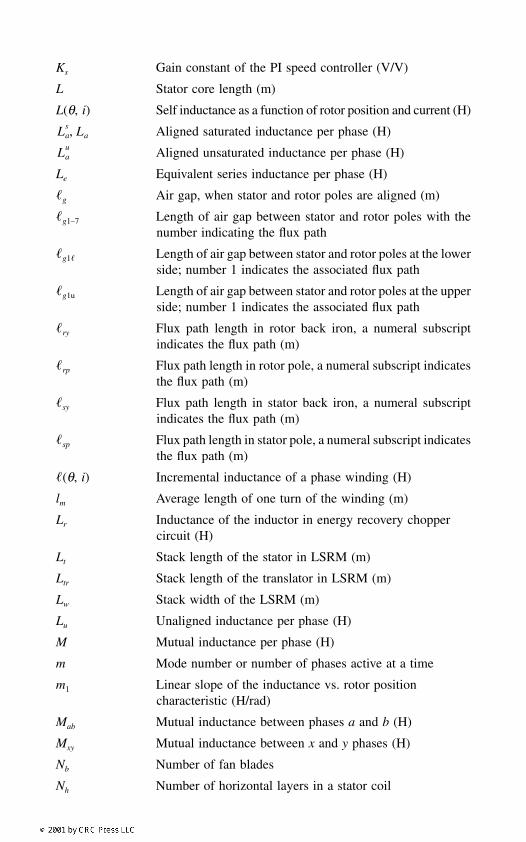
Ks Gain constant of the PI speed controller (V/V)
L Stator core length (m)
L(θ, i) Self inductance as a function of rotor position and current (H)
Aligned saturated inductance per phase (H)
Aligned unsaturated inductance per phase (H)
Le Equivalent series inductance per phase (H)
g Air gap, when stator and rotor poles are aligned (m)
g1–7 Length of air gap between stator and rotor poles with thenumber indicating the flux path
g1 Length of air gap between stator and rotor poles at the lowerside; number 1 indicates the associated flux path
g1u Length of air gap between stator and rotor poles at the upperside; number 1 indicates the associated flux path
ry Flux path length in rotor back iron, a numeral subscriptindicates the flux path (m)
rp Flux path length in rotor pole, a numeral subscript indicatesthe flux path (m)
sy Flux path length in stator back iron, a numeral subscriptindicates the flux path (m)
sp Flux path length in stator pole, a numeral subscript indicatesthe flux path (m)
(θ, i) Incremental inductance of a phase winding (H)
lm Average length of one turn of the winding (m)
Lr Inductance of the inductor in energy recovery choppercircuit (H)
Lt Stack length of the stator in LSRM (m)
Ltr Stack length of the translator in LSRM (m)
Lw Stack width of the LSRM (m)
Lu Unaligned inductance per phase (H)
M Mutual inductance per phase (H)
m Mode number or number of phases active at a time
m1 Linear slope of the inductance vs. rotor position characteristic (H/rad)
Mab Mutual inductance between phases a and b (H)
Mxy Mutual inductance between x and y phases (H)
Nb Number of fan blades
Nh Number of horizontal layers in a stator coil
Las La,
Lau
0838_Frame_FM.fm Page xxvii Monday, May 21, 2001 6:47 AM
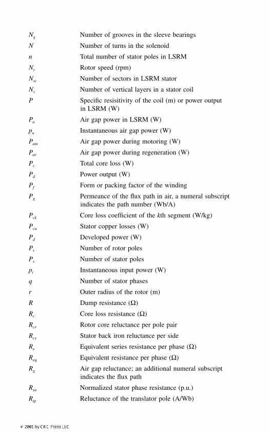
Ng Number of grooves in the sleeve bearings
N Number of turns in the solenoid
n Total number of stator poles in LSRM
Nr Rotor speed (rpm)
Nsc Number of sectors in LSRM stator
Nv Number of vertical layers in a stator coil
P Specific resisitivity of the coil (m) or power output in LSRM (W)
Pa Air gap power in LSRM (W)
pa Instantaneous air gap power (W)
Pam Air gap power during motoring (W)
Par Air gap power during regeneration (W)
Pc Total core loss (W)
Pd Power output (W)
Pf Form or packing factor of the winding
Pg Permeance of the flux path in air, a numeral subscript indicates the path number (Wb/A)
Pck Core loss coefficient of the kth segment (W/kg)
Pcu Stator copper losses (W)
Pd Developed power (W)
Pr Number of rotor poles
Ps Number of stator poles
pi Instantaneous input power (W)
q Number of stator phases
r Outer radius of the rotor (m)
R Dump resistance (Ω)
Rc Core loss resistance (Ω)
Rcr Rotor core reluctance per pole pair
Rcs Stator back iron reluctance per side
Re Equivalent series resistance per phase (Ω)
Req Equivalent resistance per phase (Ω)
Rg Air gap reluctance; an additional numeral subscriptindicates the flux path
Rsn Normalized stator phase resistance (p.u.)
Rtp Reluctance of the translator pole (A/Wb)
0838_Frame_FM.fm Page xxviii Monday, May 21, 2001 6:47 AM
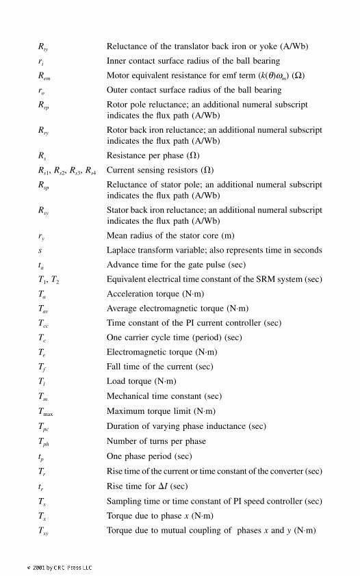
Rty Reluctance of the translator back iron or yoke (A/Wb)
ri Inner contact surface radius of the ball bearing
Rem Motor equivalent resistance for emf term (k(θ)ωm) (Ω)
ro Outer contact surface radius of the ball bearing
Rrp Rotor pole reluctance; an additional numeral subscriptindicates the flux path (A/Wb)
Rry Rotor back iron reluctance; an additional numeral subscriptindicates the flux path (A/Wb)
Rs Resistance per phase ()
Rs1, Rs2, Rs3, Rs4 Current sensing resistors ()
Rsp Reluctance of stator pole; an additional numeral subscriptindicates the flux path (A/Wb)
Rsy Stator back iron reluctance; an additional numeral subscriptindicates the flux path (A/Wb)
ry Mean radius of the stator core (m)
s Laplace transform variable; also represents time in seconds
ta Advance time for the gate pulse (sec)
T1, T2 Equivalent electrical time constant of the SRM system (sec)
Ta Acceleration torque (N⋅m)
Tav Average electromagnetic torque (N⋅m)
Tcc Time constant of the PI current controller (sec)
Tc One carrier cycle time (period) (sec)
Te Electromagnetic torque (N·m)
Tf Fall time of the current (sec)
Tl Load torque (N·m)
Tm Mechanical time constant (sec)
Tmax Maximum torque limit (N⋅m)
Tpc Duration of varying phase inductance (sec)
Tph Number of turns per phase
tp One phase period (sec)
Tr Rise time of the current or time constant of the converter (sec)
tr Rise time for I (sec)
Ts Sampling time or time constant of PI speed controller (sec)
Tx Torque due to phase x (N⋅m)
Txy Torque due to mutual coupling of phases x and y (N⋅m)
0838_Frame_FM.fm Page xxix Monday, May 21, 2001 6:47 AM
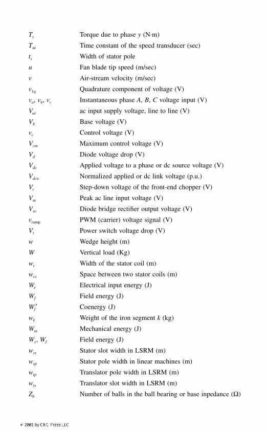
Ty Torque due to phase y (N⋅m)
Tω Time constant of the speed transducer (sec)
ts Width of stator pole
u Fan blade tip speed (m/sec)
v Air-stream velocity (m/sec)
v1q Quadrature component of voltage (V)
va, vb, vc Instantaneous phase A, B, C voltage input (V)
Vac ac input supply voltage, line to line (V)
Vb Base voltage (V)
vc Control voltage (V)
Vcm Maximum control voltage (V)
Vd Diode voltage drop (V)
Vdc Applied voltage to a phase or dc source voltage (V)
Vdcn Normalized applied or dc link voltage (p.u.)
Vi Step-down voltage of the front-end chopper (V)
Vm Peak ac line input voltage (V)
Vro Diode bridge rectifier output voltage (V)
vramp PWM (carrier) voltage signal (V)
Vt Power switch voltage drop (V)
w Wedge height (m)
W Vertical load (Kg)
wc Width of the stator coil (m)
wcs Space between two stator coils (m)
We Electrical input energy (J)
Wf Field energy (J)
Wf′ Coenergy (J)
wk Weight of the iron segment k (kg)
Wm Mechanical energy (J)
Ws, Wf Field energy (J)
wss Stator slot width in LSRM (m)
wsp Stator pole width in linear machines (m)
wtp Translator pole width in LSRM (m)
wts Translator slot width in LSRM (m)
Zb Number of balls in the ball bearing or base inpedance (Ω)
0838_Frame_FM.fm Page xxx Monday, May 21, 2001 6:47 AM
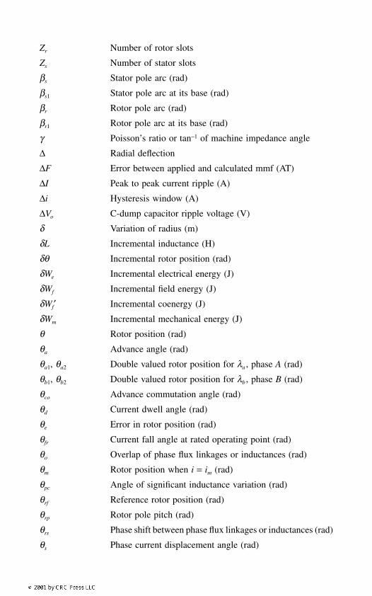
Zr Number of rotor slots
Zs Number of stator slots
βs Stator pole arc (rad)
βs1 Stator pole arc at its base (rad)
βr Rotor pole arc (rad)
βr1 Rotor pole arc at its base (rad)
γ Poisson’s ratio or tan−1 of machine impedance angle
∆ Radial deflection
∆F Error between applied and calculated mmf (AT)
∆I Peak to peak current ripple (A)
∆i Hysteresis window (A)
∆Vo C-dump capacitor ripple voltage (V)
δ Variation of radius (m)
δL Incremental inductance (H)
δθ Incremental rotor position (rad)
δWe Incremental electrical energy (J)
δWf Incremental field energy (J)
δWf′ Incremental coenergy (J)
δWm Incremental mechanical energy (J)
θ Rotor position (rad)
θa Advance angle (rad)
θa1, θa2 Double valued rotor position for λa , phase A (rad)
θb1, θb2 Double valued rotor position for λb , phase B (rad)
θco Advance commutation angle (rad)
θd Current dwell angle (rad)
θe Error in rotor position (rad)
θfr Current fall angle at rated operating point (rad)
θo Overlap of phase flux linkages or inductances (rad)
θm Rotor position when i = im (rad)
θpc Angle of significant inductance variation (rad)
θrf Reference rotor position (rad)
θrp Rotor pole pitch (rad)
θrs Phase shift between phase flux linkages or inductances (rad)
θs Phase current displacement angle (rad)
0838_Frame_FM.fm Page xxxi Monday, May 21, 2001 6:47 AM

θst Initial rotor position at starting (rad)
λ Flux linkage
λa Flux linkages at aligned position (Wb-T)
λe Expected phase flux linkages (volt-sec)
λen nth phase flux linkages error (volt-sec)
λm Phase flux linkages (volt-sec)
λn nth phase flux linkages (volt-sec)
λsn Observer nth-phase flux linkages (volt-sec)
λu Flux linkages at unaligned position (Wb-T)
ρ Mass density of the lamination material (Kg/m3)
σs Ratio between aligned and unaligned inductance at saturation
σu Ratio between aligned unsaturated inductance andunaligned inductance
τ Time constant for linear operation (sec)
τa Aligned time constant (sec)
τc Core loss time constant (sec)
τf Current ball time (sec)
τr Current rise time (sec)
τu Unaligned time constant (sec)
φ Flux in the air gap during overlap of stator and rotor polesin rotary SRM or flux in stator pole in LSRM (Wb)
ω Angular natural frequency (rad/sec)
ωc Angular switching frequency (rad/sec)
ωcs PWM carrier frequency in inactive phases for probing (rad/sec)
ωe Error rotor speed (rad/sec)
ωm Rotor speed (mechanical) (rad/sec)
ωmr Rated mechanical speed (rad/sec)
ωn Natural frequency of oscillation (rad/sec)
ωr Rotor speed signal (V)
Rotor speed reference signal (V)
ωrs Resonant frequency (rad/sec)
ωsm Observer rotor speed (rad/sec)
µr Relative permeability of the iron
ζ Damping ratio
ωr
0838_Frame_FM.fm Page xxxii Monday, May 21, 2001 6:47 AM