Embed Size (px)
Citation preview
Handbook for the SXVR-H18 Issue 1 March 2010
1
SXVR-H18CCD camera user manual
Thank you for purchasing a Starlight Xpress CCD camera. We hope that you will bevery satisfied with its performance. The SXVR-H18 is a medium format, high-resolution cooled CCD camera, especially designed for astronomical imaging. TheSXVR-H18 uses a Kodak KAF8300 ‘Full Frame’ CCD, with 3326(H) X 2504(V)pixels in a 17.96mm x 13.52mm active area. The use of high performance microlenseson the CCD surface gives the greatest possible throughput of light to the pixels andthe resulting QE is very good over the entire visible spectrum. Our new ‘R’ typeUSB2 interface hardware gives an exceptionally fast download speed of about 2megapixels per second, and so the SXVR-H18 can download a full resolution 16 bitimage in only 4.5 seconds.
The H18 is unusual in that it is the first SX camera to incorporate a mechanicalshutter. This is required for correct operation of its full-frame CCD chip, but alsopermits the user to easily take dark frames when required. However, the mechanicalcycle time does limit the shortest practical exposure time to about 0.05 seconds.
Handbook for the SXVR-H18 Issue 1 March 2010
2
Please take a few minutes to study the contents of this manual, which will help you toget the camera into operation quickly and without problems. I am sure that you wantto see some results as soon as possible, so please move on to the ‘Quick Start’ section,which follows. A more detailed description of imaging techniques will be found in alater part of this manual.
‘Quick Starting’ your SXVR-H18 system
In the shipping container you will find the following items:
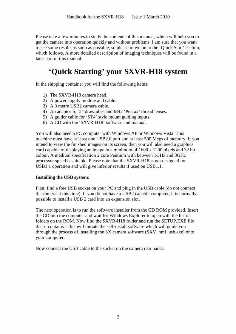
1) The SXVR-H18 camera head.2) A power supply module and cable.3) A 3 metre USB2 camera cable.4) An adaptor for 2” drawtubes and M42 ‘Pentax’ thread lenses.5) A guider cable for ‘ST4’ style mount guiding inputs.6) A CD with the ‘SXVR-H18’ software and manual.
You will also need a PC computer with Windows XP or Windows Vista. Thismachine must have at least one USB2.0 port and at least 500 Megs of memory. If youintend to view the finished images on its screen, then you will also need a graphicscard capable of displaying an image in a minimum of 1600 x 1200 pixels and 32 bitcolour. A medium specification 2 core Pentium with between 1GHz and 3GHzprocessor speed is suitable. Please note that the SXVR-H18 is not designed forUSB1.1 operation and will give inferior results if used on USB1.1.
Installing the USB system:
First, find a free USB socket on your PC and plug in the USB cable (do not connectthe camera at this time). If you do not have a USB2 capable computer, it is normallypossible to install a USB 2 card into an expansion slot.
The next operation is to run the software installer from the CD ROM provided. Insertthe CD into the computer and wait for Windows Explorer to open with the list offolders on the ROM. Now find the SXVR-H18 folder and run the SETUP.EXE filethat it contains – this will initiate the self-install software which will guide youthrough the process of installing the SX camera software (SXV_hmf_usb.exe) ontoyour computer.
Now connect the USB cable to the socket on the camera rear panel.
Handbook for the SXVR-H18 Issue 1 March 2010
3
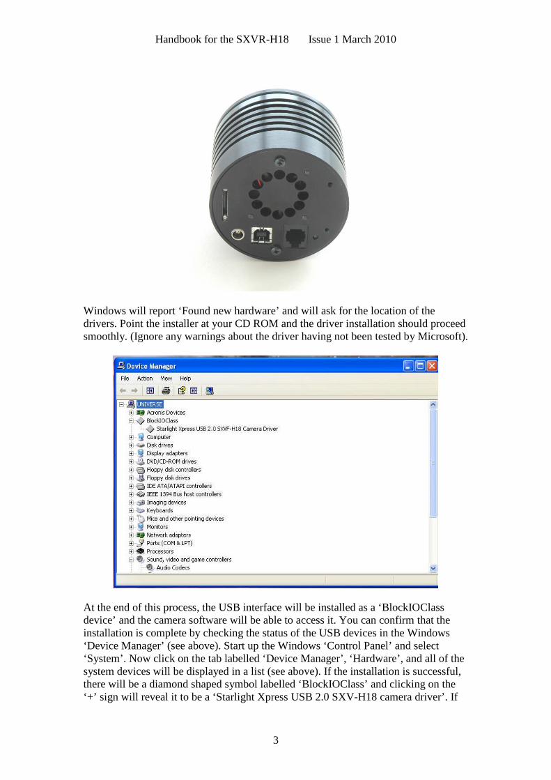
Windows will report ‘Found new hardware’ and will ask for the location of thedrivers. Point the installer at your CD ROM and the driver installation should proceedsmoothly. (Ignore any warnings about the driver having not been tested by Microsoft).
At the end of this process, the USB interface will be installed as a ‘BlockIOClassdevice’ and the camera software will be able to access it. You can confirm that theinstallation is complete by checking the status of the USB devices in the Windows‘Device Manager’ (see above). Start up the Windows ‘Control Panel’ and select‘System’. Now click on the tab labelled ‘Device Manager’, ‘Hardware’, and all of thesystem devices will be displayed in a list (see above). If the installation is successful,there will be a diamond shaped symbol labelled ‘BlockIOClass’ and clicking on the‘+’ sign will reveal it to be a ‘Starlight Xpress USB 2.0 SXV-H18 camera driver’. If
Handbook for the SXVR-H18 Issue 1 March 2010
4
this device shows as faulty, try clicking on it and selecting ‘properties’ and then‘update driver’. Following the on screen instructions will allow you to re-select thecorrect inf file (SXVIO_H18_128.inf) and driver files (SXVIO.sys and generic.sys),which should fix the problem.
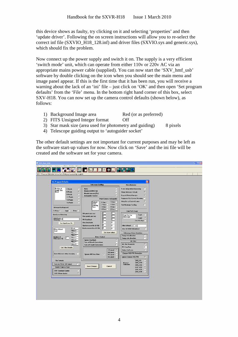
Now connect up the power supply and switch it on. The supply is a very efficient‘switch mode’ unit, which can operate from either 110v or 220v AC via anappropriate mains power cable (supplied). You can now start the ‘SXV_hmf_usb’software by double clicking on the icon when you should see the main menu andimage panel appear. If this is the first time that it has been run, you will receive awarning about the lack of an ‘ini’ file – just click on ‘OK’ and then open ‘Set programdefaults’ from the ‘File’ menu. In the bottom right hand corner of this box, selectSXV-H18. You can now set up the camera control defaults (shown below), asfollows:
1) Background Image area Red (or as preferred)2) FITS Unsigned Integer format Off3) Star mask size (area used for photometry and guiding) 8 pixels4) Telescope guiding output to ‘autoguider socket’
The other default settings are not important for current purposes and may be left asthe software start-up values for now. Now click on ‘Save’ and the ini file will becreated and the software set for your camera.
Handbook for the SXVR-H18 Issue 1 March 2010
5
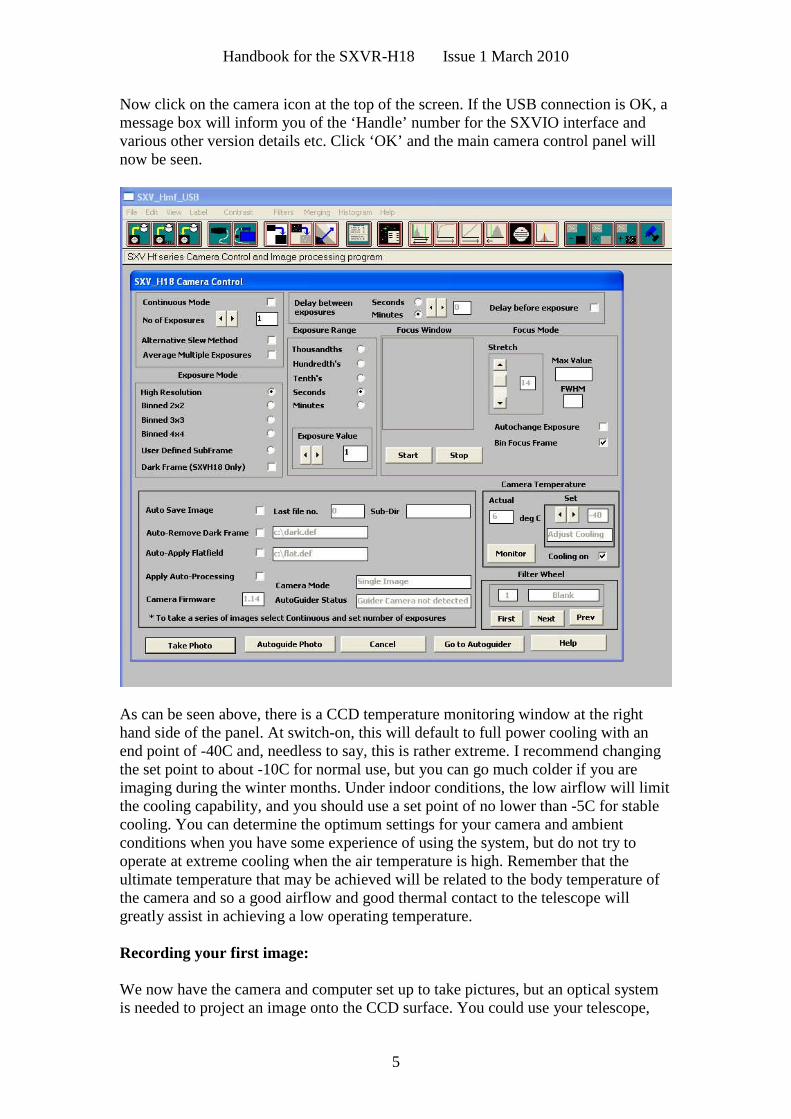
Now click on the camera icon at the top of the screen. If the USB connection is OK, amessage box will inform you of the ‘Handle’ number for the SXVIO interface andvarious other version details etc. Click ‘OK’ and the main camera control panel willnow be seen.
As can be seen above, there is a CCD temperature monitoring window at the righthand side of the panel. At switch-on, this will default to full power cooling with anend point of -40C and, needless to say, this is rather extreme. I recommend changingthe set point to about -10C for normal use, but you can go much colder if you areimaging during the winter months. Under indoor conditions, the low airflow will limitthe cooling capability, and you should use a set point of no lower than -5C for stablecooling. You can determine the optimum settings for your camera and ambientconditions when you have some experience of using the system, but do not try tooperate at extreme cooling when the air temperature is high. Remember that theultimate temperature that may be achieved will be related to the body temperature ofthe camera and so a good airflow and good thermal contact to the telescope willgreatly assist in achieving a low operating temperature.
Recording your first image:
We now have the camera and computer set up to take pictures, but an optical systemis needed to project an image onto the CCD surface. You could use your telescope,
Handbook for the SXVR-H18 Issue 1 March 2010
6
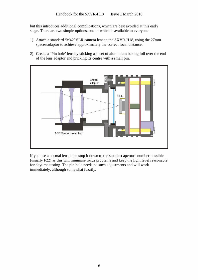
but this introduces additional complications, which are best avoided at this earlystage. There are two simple options, one of which is available to everyone:
1) Attach a standard ‘M42’ SLR camera lens to the SXVR-H18, using the 27mmspacer/adaptor to achieve approximately the correct focal distance.
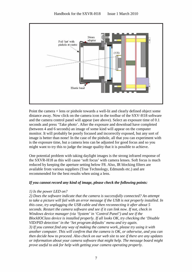
2) Create a ‘Pin hole’ lens by sticking a sheet of aluminium baking foil over the endof the lens adaptor and pricking its centre with a small pin.
If you use a normal lens, then stop it down to the smallest aperture number possible(usually F22) as this will minimise focus problems and keep the light level reasonablefor daytime testing. The pin hole needs no such adjustments and will workimmediately, although somewhat fuzzily.
Handbook for the SXVR-H18 Issue 1 March 2010
7
Point the camera + lens or pinhole towards a well-lit and clearly defined object somedistance away. Now click on the camera icon in the toolbar of the SXV-H18 softwareand the camera control panel will appear (see above). Select an exposure time of 0.1seconds and press ‘Take photo’. After the exposure and download have completed(between 4 and 6 seconds) an image of some kind will appear on the computermonitor. It will probably be poorly focused and incorrectly exposed, but any sort ofimage is better than none! In the case of the pinhole, all that you can experiment withis the exposure time, but a camera lens can be adjusted for good focus and so youmight want to try this to judge the image quality that it is possible to achieve.
One potential problem with taking daylight images is the strong infrared response ofthe SXVR-H18 as this will cause ‘soft focus’ with camera lenses. Soft focus is muchreduced by keeping the aperture setting below F8. Also, IR blocking filters areavailable from various suppliers (True Technology, Edmunds etc.) and arerecommended for the best results when using a lens.
If you cannot record any kind of image, please check the following points:
1) Is the power LED on?2) Does the software indicate that the camera is successfully connected? An attemptto take a picture will fail with an error message if the USB is not properly installed. Inthis case, try unplugging the USB cable and then reconnecting it after about 5seconds. Restart the camera software and see if it can link now. If not, check inWindows device manager (via ‘System’ in ‘Control Panel’) and see if theBlockIOClass device is installed properly. If all looks OK, try checking the ‘DisableVID/PID detection’ in the ‘Set program defaults’ menu and try again.3) If you cannot find any way of making the camera work, please try using it withanother computer. This will confirm that the camera is OK, or otherwise, and you canthen decide how to proceed. Also check on our web site to see if there are any updatesor information about your camera software that might help. The message board mightprove useful to ask for help with getting your camera operating properly.
Handbook for the SXVR-H18 Issue 1 March 2010
8
Our guarantee ensures that any electrical faults are corrected quickly and at no costto the customer.
Enhancing your image:
Your first image may now be reasonably good, but it is unlikely to be as clear andsharp as it could be. Improved focusing and exposure selection may correct theseshortcomings, and you may like to try them before applying any image enhancementwith the software. However, there will come a point when you say, ‘That’s the bestthat I can get’ and you will want to experiment with various filters and contrastoperations. In the case of daylight images, the processing options are many, but thereare few that will improve the picture in a useful way.
The most useful of these are the ‘Normal Contrast Stretch’ and the ‘High Pass LowPower’ filter. The high pass filter gives a moderate improvement in the imagesharpness, and this can be very effective on daylight images. Too much high passfiltering results in dark borders around well-defined features and will increase the‘noise’ in an image to unacceptable levels, but the ‘Low Power’ filter is close tooptimum and gives a nicely sharpened picture.
The ‘Contrast’ routines are used to brighten (or dull) the image highlights andshadows. A ‘Normal’ stretch is a simple linear operation, where two pointers (the‘black’ and ‘white’ limits) can be set at either side of the image histogram and used todefine new start and end points. The image data is then mathematically modified sothat any pixels that are to the left of the ‘black’ pointer are set to black and any pixelsto the right of the ‘white’ pointer are set to white. The pixels with values between thepointers are modified to fit the new brightness distribution. Try experimenting withthe pointer positions until the image has a pleasing brightness and ‘crispness’.
At this point, you will have a working knowledge of how to take and process anSXVR-H18 image. It is time to move on to astronomical imaging, which has its own,unique, set of problems!
*********************************************************************
Astronomical Imaging with the SXVR-H18
1) Getting the image onto the CCD:
It is essential to set up a good optical match between your H18 and your telescope.The H18 has a large CCD area and so many of the popular ‘SCT’ ‘scopes are unableto provide good quality star images over the large chip. Because of this limitation, theH18 was designed for use with a wide field highly corrected refractor, such as theTakahashi FSQ106 or similar, but some flat-field reflectors will be OK. A particularlygood option is the ‘Hyperstar’ adaptor from ‘Starizona’, which works well with thelarger SCT ‘scopes.
Handbook for the SXVR-H18 Issue 1 March 2010
9
As a general guide, most CCD astronomers try to maintain an image scale of about 2arc seconds per pixel for deep sky images. This matches the telescope resolution tothe CCD resolution and avoids ‘undersampling’ the image, which can result in squarestars and other unwanted effects. To calculate the optimum focal length required forthis condition to exist, you can use the following simple equation:
F = Pixel size * 205920 / Resolution (in arc seconds)
In the case of the SXVR-H18 and a 2 arc seconds per pixel resolution, we get
F = 0.0054 * 205920 / 2 = 556mm
Because of the large CCD size used in the H18, field vignetting and field curvaturewill be a problem with many general purpose telescopes. The larger SCTs and manyof the new ‘APO’ refractors will not suffer so badly from this issue, but you may haveto compromise on vignetting and usable field size when imaging with a less highlycorrected instrument. Application of a ‘flat field’ to your images will help to removethe edge shading, but the star images may well be badly distorted around theperiphery of the image, due to field curvature.
Achieving a good focus:
The SXV_H18 software has a focus routine that will repeatedly download and displaya 100 x 100 pixel segment of the image at a relatively high speed. This focus windowmay be positioned anywhere in the camera field and can be displayed with anadjustable degree of automatic contrast stretching (for focusing on faint stars). To usethis mode, start up the software and select the H18 camera interface (File menu). Setthe camera mode to ‘Bin 1x1’ and select an exposure time of 1 second. Press ‘TakePicture’ and wait for the image to download. There is a good chance that yourselected star will appear somewhere within the image frame and with luck it should beclose to a sharp focus. If the focus is still poor, then it may appear as a pale disk oflight, sometimes with a dark centre (the secondary mirror shadow in an SCT, orNewtonian). Now select the ‘File’ menu again and click on ‘Focus frame centre’; youcan now use the mouse pointer to click on the star image and the new focus frame co-ordinates will be displayed. Now return to the camera interface window and click on‘Start’ in the Focus frame. The computer will now display a continuous series of 100x 100 pixel images in the focus window and you should see your selected star appearsomewhere close to the centre. A ‘peak value’ (the value of the brightest pixel) willalso be shown in the adjacent text box and this can be used as an indication of thefocus accuracy. Although the peak value is sensitive to vibration and seeing, it tendstowards a maximum as the focus is optimised. Carefully adjust the focus control onyour telescope until the image is as sharp as possible and the peak value reaches amaximum. Wait for any vibration to die down before accepting the reading as reliableand watch out for bursts of bad seeing, which reduce the apparent focus quality. Quiteoften, the peak value will increase to the point where it is ‘off scale’ at 4095 and inthis case you must halt the focus sequence and select a shorter exposure if you wish touse the peak value as an indicator. Once you are happy with the focus qualityachieved, you might like to trim the settings of your par-focal or flip mirror eyepieceto match the current camera position. Although you can reach a good focus by the
Handbook for the SXVR-H18 Issue 1 March 2010
10
above method, many observers prefer to use additional aids, such as Hartmann masks(an objective cover with two or three spaced holes) or diffraction bars (narrow parallelrods across the telescope aperture). These make the point of precise focus easier todetermine by creating ‘double images’ or bright diffraction spikes around stars, whichmerge at the setting of exact focus. The 12-16 bit slider control allows you to adjustthe contrast of the focus frame for best visibility of the star image. It defaults tomaximum stretch (12 bits), which is generally ideal for stars, but a lower stretch valueis better for focusing on planets.
Taking your first astronomical image:
I will assume that you are now set up with a focused camera attached to a telescopewith an operating sidereal drive. If so, you are now in a position to take a moderatelylong exposure of some interesting deep-sky astronomical objects. As most drives arenot very accurate beyond a minute or two of exposure time, I suggest that you find afairly bright object to image, such as M42, M13, M27 or M57. There are many othersto choose from, but these are good examples.
Use the finder to align on your chosen object and then centre accurately by using thefocus frame and a short exposure of between 1 and 5 seconds. The ’12-16 bit’ sliderin the focus frame allows you to adjust the image contrast if you find that the object istoo faint with a short exposure. Once properly centred and focused, take an exposureof about 60 seconds, using the ‘Bin 1x1’ mode and observe the result. Initially, theimage may appear rather barren and show only a few stars, however, there is a greatdeal of data hidden from view. You can get to see a lot of this, without affecting theimage data, if you go to the ‘View’ menu and select ‘Auto Contrast Stretch Image’.The faint image data will then appear in considerable detail and I think that you willbe impressed by the result!
If you are happy with the image, go to the ‘File’ menu and save it in a convenientdirectory. Now you need a ‘dark frame’, if the best results are to be extracted fromyour raw image. To take this, just cover the telescope objective with the lens cap, ordrop the flip mirror to block the light path to the CCD (make sure that this is lighttight), and take another 60 second exposure. This image will be a picture of the darksignal generated during your exposure and it should be saved with your image for usein processing the picture. The SXVR-H18 generates relatively little dark signal and sodark frames are not essential for short exposures of less than a few minutes, but it is agood idea to record at least one for each exposure time used during an imagingsession. As variations in ambient temperature can affect the dark signal, it is best totake the dark frames within a few minutes of capturing your images. For the samereason, it is not wise to use ‘old’ dark frames if you want the best possible results,however, some software allows you to scale library dark frames to match the image(e.g. AstroArt and Maxim DL).
‘Flat fields’ are often recommended for optimising the results from your CCDcamera, but these are generally less important than dark frames, especially if youmake sure that the optical window of the camera is kept dust-free. The purpose of aflat field is to compensate for uneven illumination and sensitivity of the CCD and it isbetter to avoid the need for one by keeping the optics clean and unvignetted. I will
Handbook for the SXVR-H18 Issue 1 March 2010
11
ignore flat fielding for current purposes and describe the process in detail at a laterstage.
Processing the deep-sky image:
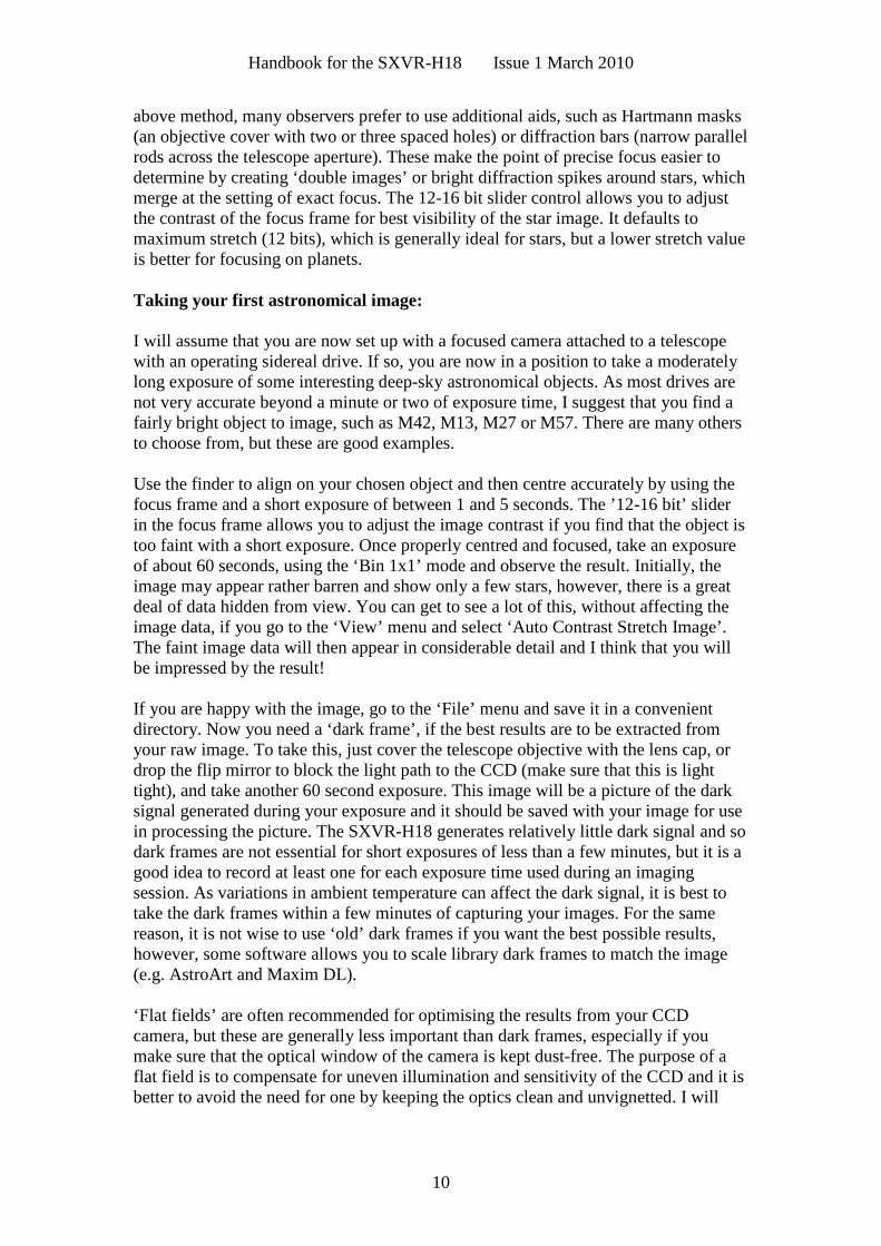
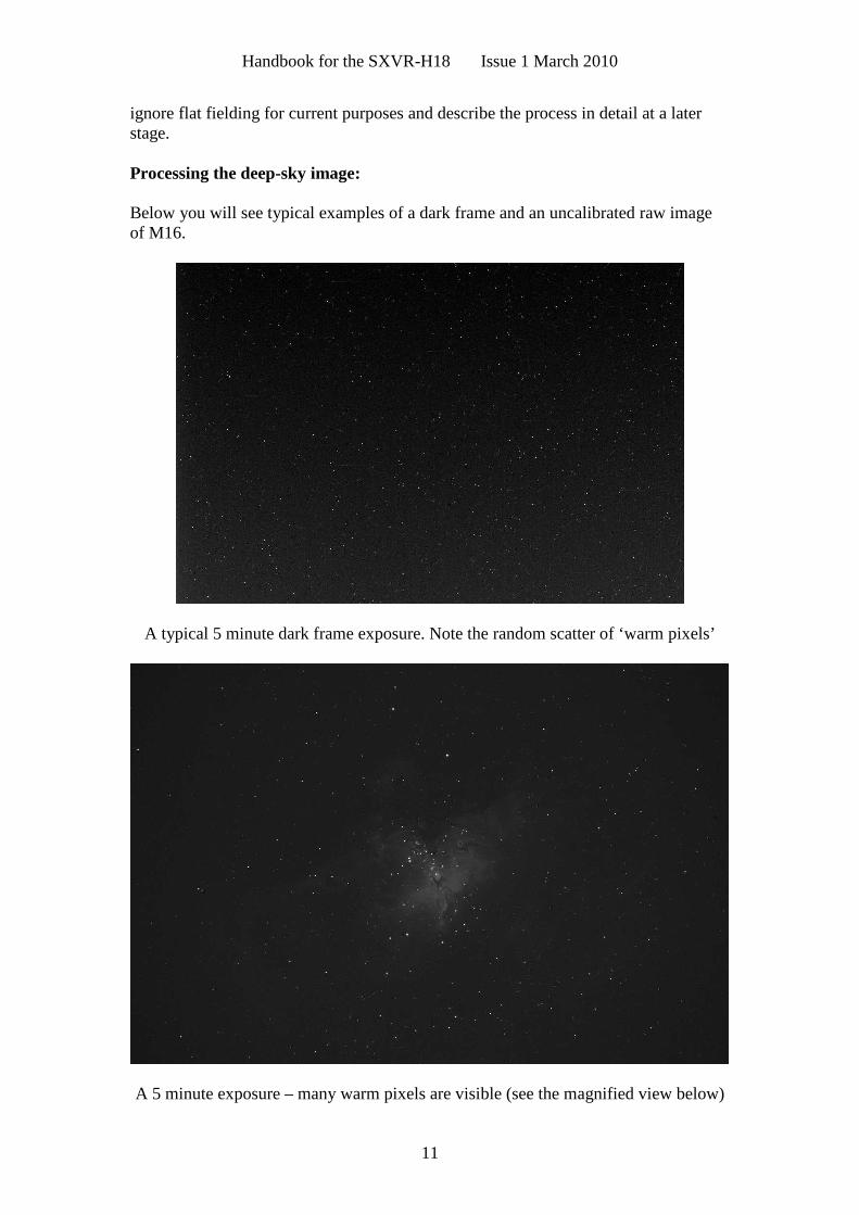
Below you will see typical examples of a dark frame and an uncalibrated raw imageof M16.
A typical 5 minute dark frame exposure. Note the random scatter of ‘warm pixels’
A 5 minute exposure – many warm pixels are visible (see the magnified view below)
Handbook for the SXVR-H18 Issue 1 March 2010
12
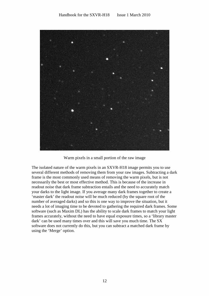
Warm pixels in a small portion of the raw image
The isolated nature of the warm pixels in an SXVR-H18 image permits you to useseveral different methods of removing them from your raw images. Subtracting a darkframe is the most commonly used means of removing the warm pixels, but is notnecessarily the best or most effective method. This is because of the increase inreadout noise that dark frame subtraction entails and the need to accurately matchyour darks to the light image. If you average many dark frames together to create a‘master dark’ the readout noise will be much reduced (by the square root of thenumber of averaged darks) and so this is one way to improve the situation, but itneeds a lot of imaging time to be devoted to gathering the required dark frames. Somesoftware (such as Maxim DL) has the ability to scale dark frames to match your lightframes accurately, without the need to have equal exposure times, so a ‘library masterdark’ can be used many times over and this will save you much time. The SXsoftware does not currently do this, but you can subtract a matched dark frame byusing the ‘Merge’ option.
Handbook for the SXVR-H18 Issue 1 March 2010
13
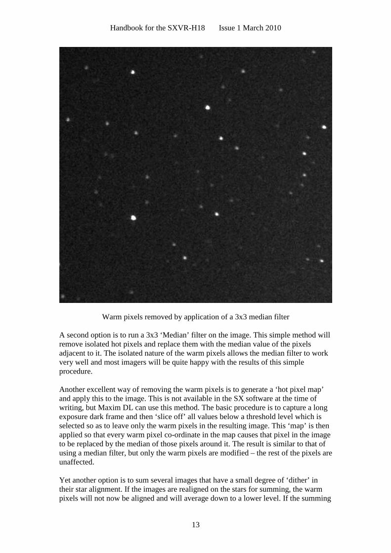
Warm pixels removed by application of a 3x3 median filter
A second option is to run a 3x3 ‘Median’ filter on the image. This simple method willremove isolated hot pixels and replace them with the median value of the pixelsadjacent to it. The isolated nature of the warm pixels allows the median filter to workvery well and most imagers will be quite happy with the results of this simpleprocedure.
Another excellent way of removing the warm pixels is to generate a ‘hot pixel map’and apply this to the image. This is not available in the SX software at the time ofwriting, but Maxim DL can use this method. The basic procedure is to capture a longexposure dark frame and then ‘slice off’ all values below a threshold level which isselected so as to leave only the warm pixels in the resulting image. This ‘map’ is thenapplied so that every warm pixel co-ordinate in the map causes that pixel in the imageto be replaced by the median of those pixels around it. The result is similar to that ofusing a median filter, but only the warm pixels are modified – the rest of the pixels areunaffected.
Yet another option is to sum several images that have a small degree of ‘dither’ intheir star alignment. If the images are realigned on the stars for summing, the warmpixels will not now be aligned and will average down to a lower level. If the summing
Handbook for the SXVR-H18 Issue 1 March 2010
14
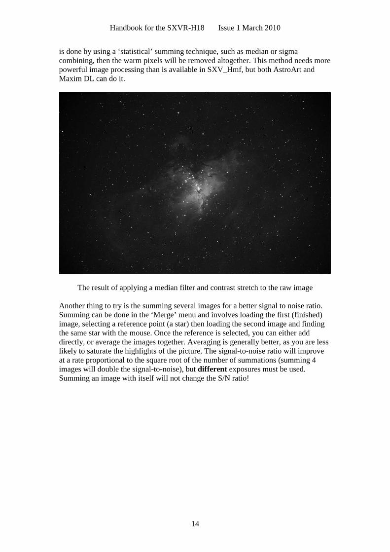
is done by using a ‘statistical’ summing technique, such as median or sigmacombining, then the warm pixels will be removed altogether. This method needs morepowerful image processing than is available in SXV_Hmf, but both AstroArt andMaxim DL can do it.
The result of applying a median filter and contrast stretch to the raw image
Another thing to try is the summing several images for a better signal to noise ratio.Summing can be done in the ‘Merge’ menu and involves loading the first (finished)image, selecting a reference point (a star) then loading the second image and findingthe same star with the mouse. Once the reference is selected, you can either adddirectly, or average the images together. Averaging is generally better, as you are lesslikely to saturate the highlights of the picture. The signal-to-noise ratio will improveat a rate proportional to the square root of the number of summations (summing 4images will double the signal-to-noise), but different exposures must be used.Summing an image with itself will not change the S/N ratio!
Handbook for the SXVR-H18 Issue 1 March 2010
15
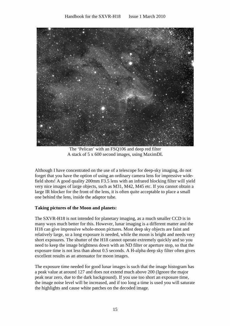
The ‘Pelican’ with an FSQ106 and deep red filterA stack of 5 x 600 second images, using MaximDL
Although I have concentrated on the use of a telescope for deep-sky imaging, do notforget that you have the option of using an ordinary camera lens for impressive wide-field shots! A good quality 200mm F3.5 lens with an infrared blocking filter will yieldvery nice images of large objects, such as M31, M42, M45 etc. If you cannot obtain alarge IR blocker for the front of the lens, it is often quite acceptable to place a smallone behind the lens, inside the adaptor tube.
Taking pictures of the Moon and planets:
The SXVR-H18 is not intended for planetary imaging, as a much smaller CCD is inmany ways much better for this. However, lunar imaging is a different matter and theH18 can give impressive whole-moon pictures. Most deep sky objects are faint andrelatively large, so a long exposure is needed, while the moon is bright and needs veryshort exposures. The shutter of the H18 cannot operate extremely quickly and so youneed to keep the image brightness down with an ND filter or aperture stop, so that theexposure time is not less than about 0.5 seconds. A H-alpha deep sky filter often givesexcellent results as an attenuator for moon images.
The exposure time needed for good lunar images is such that the image histogram hasa peak value at around 127 and does not extend much above 200 (Ignore the majorpeak near zero, due to the dark background). If you use too short an exposure time,the image noise level will be increased, and if too long a time is used you will saturatethe highlights and cause white patches on the decoded image.
Handbook for the SXVR-H18 Issue 1 March 2010
16
If you want to record an image sequence – perhaps during a lunar eclipse – you canset up the SX software to ‘Autosave’ an image sequence. To start the Autosaveprocess, call up the SXV Camera Interface and select the ‘Continuous Mode’ checkbox at the top (make sure the rest are unchecked). Now check the ‘Autosave Image’checkbox near the bottom of the window. If you now click on ‘Take Picture’ theautomatic sequence will begin and will not stop until you press a computer key. Theimages will be saved in FITs format with sequential names such as ‘Img23,Img24….’ and will be found in the ‘Autosave’ directory (or a sub-directory ofAutosave, set up in the program defaults menu).
Processing a lunar image:
Lunar images have one major advantage over deep sky images, when you come toprocess them – they are MUCH brighter, with a correspondingly better signal to noiseratio. This means that aggressive sharpening filters may be used without making theresult look very noisy and so some of the effects of poor seeing can be neutralised.
Try applying an ‘Unsharp Mask’ filter with a radius of 5 and a power of 5. This willgreatly increase the visibility of any detail on the moon, but the optimum radius andpower will have to be determined by experiment. In general terms, the larger theimage and the worse the seeing, then the wider the radius for best results. I find thatthe ‘radius 5, power 5’ values are good for most average seeing conditions. If youhave exceptionally good conditions, then a reduction to R=3, P=3 will probably give amore natural look to the image, as too large a radius and power tends to outline edgeswith dark or bright borders. As a finishing touch, the application of a Median filter ora Weighted Mean Low Pass filter can be useful to smooth out the high frequencynoise after a strong Unsharp Mask.
*********************************************************************Other features of SXV_H18
‘Slew & Sum’ imaging:
The SXVR-H18 can be used in an automatic image-stacking mode, called ‘Slew &Sum’. The camera is set to take several sequential exposures, which are automatically‘slewed’ into alignment and then summed together by the software. This mode canhelp to overcome a poor RA drive by summing images that have exposure timesshorter than the drive error period. The resulting image has more noise than a singleexposure of the same total length, but this method of imaging is still an effective wayof making long exposures.
To take an S&S image, go to the camera interface window and select an exposuretime for one image of the sequence. Do not use a very short exposure time, as theread-out noise will become dominant. About 30 seconds is a reasonable minimum.Now go to the ‘Multiple Exposure Options’ and select a number of exposures to take.You can also select to average the images, rather than adding them, and there is a‘Alternative Slew Mode’ available, which uses the correlation of image areas, ratherthan a single star. This mode can be better in dense star fields.Another option is ‘Auto remove dark frame’. This is advisable with S&S images, asthe slewing will mis-register the images with a single dark frame that is applied to the
Handbook for the SXVR-H18 Issue 1 March 2010
17
finished sequence. To use this option, you will need a dark frame, taken with the sameexposure time as a single image from the sequence. This is stored on drive C with thename ‘dark.def’
Now click on ‘Take Picture’ and the sequence will begin.
Taking and using a flat field:
Flat fields are images which display only the variations of illumination and sensitivityof the CCD, and are used to mathematically modify a wanted image in such a waythat the errors are removed. Common flat field errors are due to dust motes on thecamera window and vignetting effects in the optical system of the telescope. Dustmotes act as ‘inverse pinholes’ and cast out-of-focus images of the telescope apertureonto the CCD chip, where they appear as shadow ‘do-nuts’. Most optical systemsshow some vignetting at the edges of the field, especially when focal reducers areused. This causes a brighter centre to show in images, especially when there is a lot ofsky light to illuminate the field.
If dust motes are your main problem, it is best to clean the camera window, ratherthan to rely on a flat field to remove the do-nuts. Flat fields always increase the noisein an image and so physical dust removal is the best option. If you have seriousvignetting, first check whether the optical system can be improved. The most likelycause of this problem is trying to use too powerful a degree of optical compressionwith a focal reducer and you might want to try moving the camera closer to thereducer lens.
If you really do need to use a flat field for image correction, then it must be taken withcare. It is most important that the optical system MUST NOT be disturbed betweentaking your original images and taking the flat field. Any relative changes of focusand rotation etc. will upset the match between flat field and image and the result willbe poor correction of the errors. The other necessity for recording a good flat field is asource of very even illumination for the telescope field. This is surprisingly difficultto achieve and many designs of light source have appeared in the literature and on theWeb. These usually consist of a large lightweight box, containing several lamps andan internal coating of matt white paint, which is placed over the objective of thetelescope to provide an evenly illuminated surface. These can work well, but I prefer asimpler method, as follows:Most imaging sessions begin or end in twilight and so the dusk or dawn sky canprovide a distributed source of light for a flat field. However, using the sky directly islikely to result in recording many unwanted stars, or patches of cloud etc., so adiffuser needs to be added to the telescope. An ideal material is Mylar plasticdraughting film, obtained from an office supplies warehouse. It is strong and waterresistant and can be easily replaced if damaged. Stretch a piece of the film looselyacross the aperture of your telescope and point the instrument high in the sky, to avoidany gradient in the light near the horizon. Now take several images with exposuretimes adjusted to give a bright, but not overloaded, picture. Averaging flat fieldtogether is a good way to reduce their noise contribution and so recording 4, or more,images is a good idea.
Handbook for the SXVR-H18 Issue 1 March 2010
18
To use your flat fields, they must first have a bias frame subtracted. Although thismay appear to be unimportant with such brightly lit and short exposures, there is the‘bias offset’ of the camera in each image and this can produce an error in the finalcorrection. As we are mainly interested in the bias, any very short exposure darkframe will give a good result. The bias subtracted images should then be averagedtogether before use.After the above procedures have been executed, the flat field will be ready for use.Load up your image for processing, subtract the dark frame and then select ‘Applyflat field’ in the ‘Merge’ menu. The result should be an image with very little sign ofthe original artefacts.
********************************************************************
The accessory ports
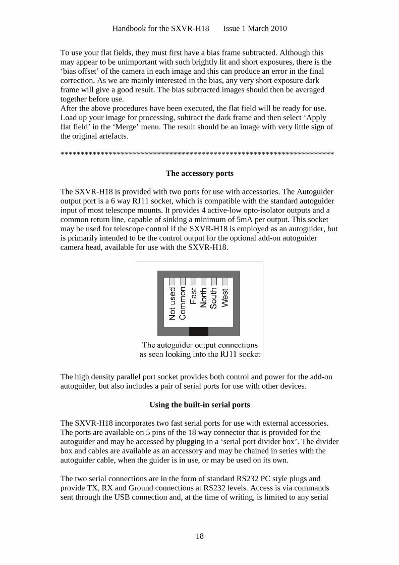
The SXVR-H18 is provided with two ports for use with accessories. The Autoguideroutput port is a 6 way RJ11 socket, which is compatible with the standard autoguiderinput of most telescope mounts. It provides 4 active-low opto-isolator outputs and acommon return line, capable of sinking a minimum of 5mA per output. This socketmay be used for telescope control if the SXVR-H18 is employed as an autoguider, butis primarily intended to be the control output for the optional add-on autoguidercamera head, available for use with the SXVR-H18.
The high density parallel port socket provides both control and power for the add-onautoguider, but also includes a pair of serial ports for use with other devices.
Using the built-in serial ports
The SXVR-H18 incorporates two fast serial ports for use with external accessories.The ports are available on 5 pins of the 18 way connector that is provided for theautoguider and may be accessed by plugging in a ‘serial port divider box’. The dividerbox and cables are available as an accessory and may be chained in series with theautoguider cable, when the guider is in use, or may be used on its own.
The two serial connections are in the form of standard RS232 PC style plugs andprovide TX, RX and Ground connections at RS232 levels. Access is via commandssent through the USB connection and, at the time of writing, is limited to any serial
Handbook for the SXVR-H18 Issue 1 March 2010
19
controls that are provided by the SXV software. It is expected that many morefunctions will be added as the software is upgraded.
*********************************************************************Using the add-on autoguider:
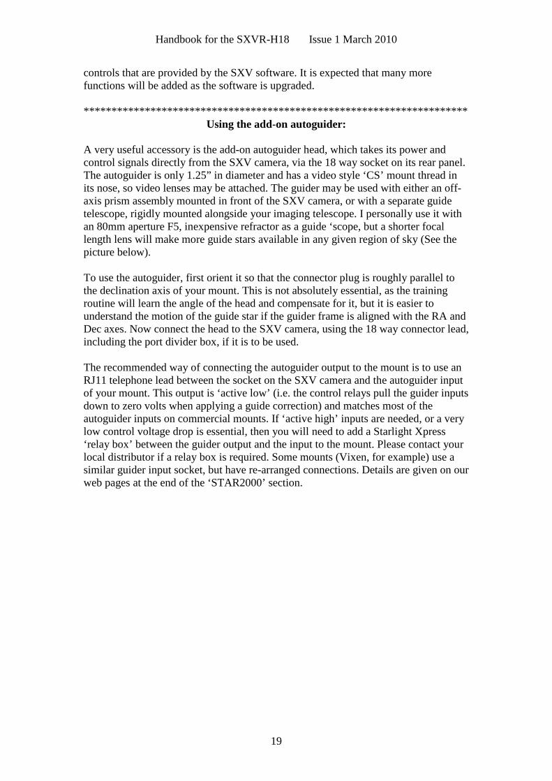
A very useful accessory is the add-on autoguider head, which takes its power andcontrol signals directly from the SXV camera, via the 18 way socket on its rear panel.The autoguider is only 1.25” in diameter and has a video style ‘CS’ mount thread inits nose, so video lenses may be attached. The guider may be used with either an off-axis prism assembly mounted in front of the SXV camera, or with a separate guidetelescope, rigidly mounted alongside your imaging telescope. I personally use it withan 80mm aperture F5, inexpensive refractor as a guide ‘scope, but a shorter focallength lens will make more guide stars available in any given region of sky (See thepicture below).
To use the autoguider, first orient it so that the connector plug is roughly parallel tothe declination axis of your mount. This is not absolutely essential, as the trainingroutine will learn the angle of the head and compensate for it, but it is easier tounderstand the motion of the guide star if the guider frame is aligned with the RA andDec axes. Now connect the head to the SXV camera, using the 18 way connector lead,including the port divider box, if it is to be used.
The recommended way of connecting the autoguider output to the mount is to use anRJ11 telephone lead between the socket on the SXV camera and the autoguider inputof your mount. This output is ‘active low’ (i.e. the control relays pull the guider inputsdown to zero volts when applying a guide correction) and matches most of theautoguider inputs on commercial mounts. If ‘active high’ inputs are needed, or a verylow control voltage drop is essential, then you will need to add a Starlight Xpress‘relay box’ between the guider output and the input to the mount. Please contact yourlocal distributor if a relay box is required. Some mounts (Vixen, for example) use asimilar guider input socket, but have re-arranged connections. Details are given on ourweb pages at the end of the ‘STAR2000’ section.
Handbook for the SXVR-H18 Issue 1 March 2010
20
The autoguider installed on a 80mm refractor guide ‘scope in the author’s garden
To use the autoguider, please proceed as follows:
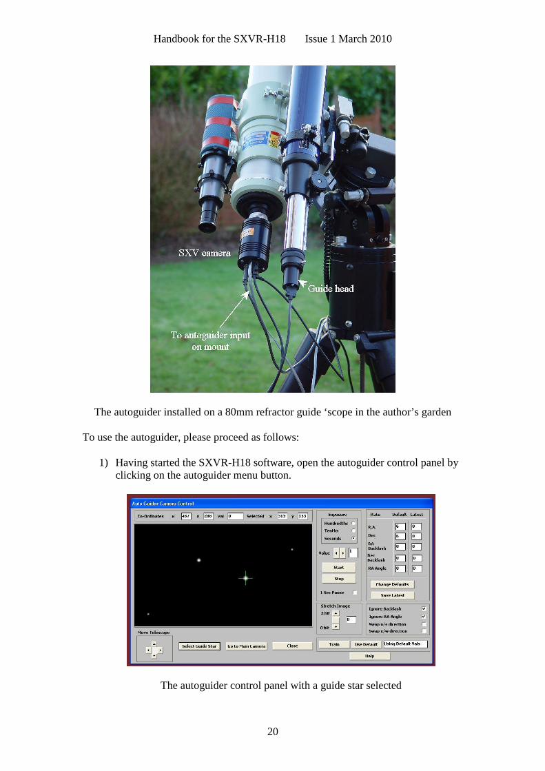
1) Having started the SXVR-H18 software, open the autoguider control panel byclicking on the autoguider menu button.
The autoguider control panel with a guide star selected
Handbook for the SXVR-H18 Issue 1 March 2010
21
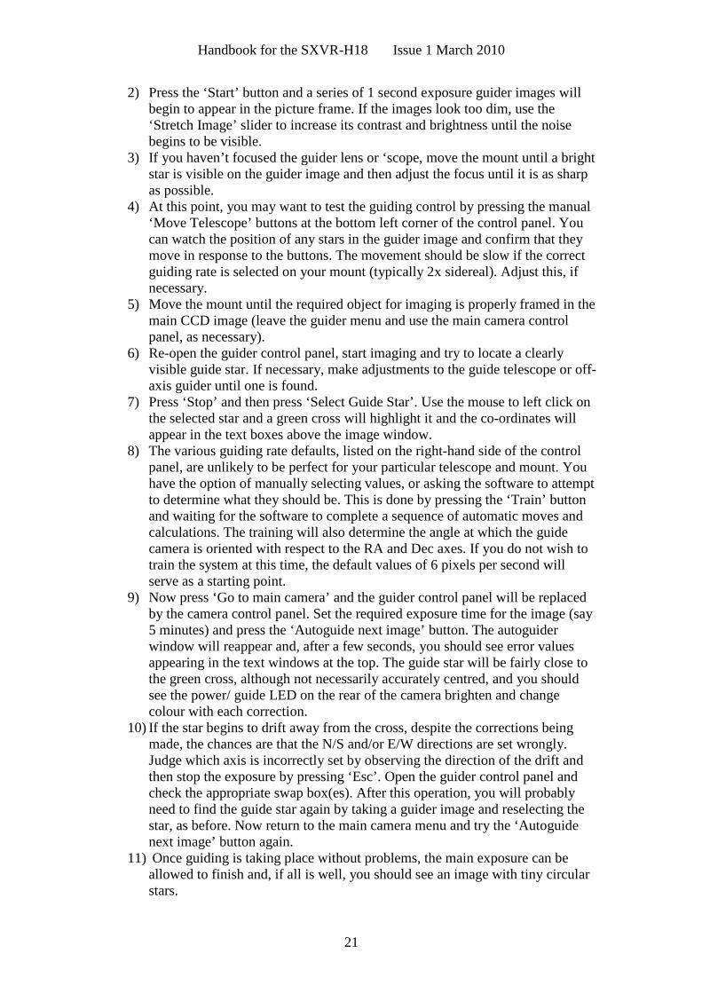
2) Press the ‘Start’ button and a series of 1 second exposure guider images willbegin to appear in the picture frame. If the images look too dim, use the‘Stretch Image’ slider to increase its contrast and brightness until the noisebegins to be visible.
3) If you haven’t focused the guider lens or ‘scope, move the mount until a brightstar is visible on the guider image and then adjust the focus until it is as sharpas possible.
4) At this point, you may want to test the guiding control by pressing the manual‘Move Telescope’ buttons at the bottom left corner of the control panel. Youcan watch the position of any stars in the guider image and confirm that theymove in response to the buttons. The movement should be slow if the correctguiding rate is selected on your mount (typically 2x sidereal). Adjust this, ifnecessary.
5) Move the mount until the required object for imaging is properly framed in themain CCD image (leave the guider menu and use the main camera controlpanel, as necessary).
6) Re-open the guider control panel, start imaging and try to locate a clearlyvisible guide star. If necessary, make adjustments to the guide telescope or off-axis guider until one is found.
7) Press ‘Stop’ and then press ‘Select Guide Star’. Use the mouse to left click onthe selected star and a green cross will highlight it and the co-ordinates willappear in the text boxes above the image window.
8) The various guiding rate defaults, listed on the right-hand side of the controlpanel, are unlikely to be perfect for your particular telescope and mount. Youhave the option of manually selecting values, or asking the software to attemptto determine what they should be. This is done by pressing the ‘Train’ buttonand waiting for the software to complete a sequence of automatic moves andcalculations. The training will also determine the angle at which the guidecamera is oriented with respect to the RA and Dec axes. If you do not wish totrain the system at this time, the default values of 6 pixels per second willserve as a starting point.
9) Now press ‘Go to main camera’ and the guider control panel will be replacedby the camera control panel. Set the required exposure time for the image (say5 minutes) and press the ‘Autoguide next image’ button. The autoguiderwindow will reappear and, after a few seconds, you should see error valuesappearing in the text windows at the top. The guide star will be fairly close tothe green cross, although not necessarily accurately centred, and you shouldsee the power/ guide LED on the rear of the camera brighten and changecolour with each correction.
10) If the star begins to drift away from the cross, despite the corrections beingmade, the chances are that the N/S and/or E/W directions are set wrongly.Judge which axis is incorrectly set by observing the direction of the drift andthen stop the exposure by pressing ‘Esc’. Open the guider control panel andcheck the appropriate swap box(es). After this operation, you will probablyneed to find the guide star again by taking a guider image and reselecting thestar, as before. Now return to the main camera menu and try the ‘Autoguidenext image’ button again.
11) Once guiding is taking place without problems, the main exposure can beallowed to finish and, if all is well, you should see an image with tiny circularstars.
Handbook for the SXVR-H18 Issue 1 March 2010
22
If the stars are not circular, you may need to alter the guiding parameters, orinvestigate the rigidity and drive performance of your mount. A lot of informationcan be deduced by watching the behaviour of the guide star in the guider frame. Ifit is continually moving between two locations, either side of the green cross, thenthe RA or Dec pixels per second value is set too low. The higher these values areset, the gentler the guiding becomes. Too low a value will cause an over-aggressive correction to be made and result in oscillation of the star positionbetween two points.
Another source of guiding errors can be a too accurately balanced telescopemount! Good balance can result in the telescope mount ‘bouncing’ between thegear teeth as corrections are made. A simple fix is to add a weight of about 0.5kg(1 pound) on the eastern end of the declination axis, so that there is always somepressure acting against the gear teeth.
Getting a good result from an autoguider will often entail a lot of detective workto eliminate the sources of gear error, telescope flexure, mirror shift etc., but thefinal result is well worth the effort!
*********************************************************************
Camera maintenance:
Very little maintenance is needed to keep the SXVR-H18 in excellent operating order,however two problems, which are common to all CCD equipment, are likely to showup on occasion. These are dust and condensation.
Removing Dust:
1) Dust can be deposited on either the optical window (not a big problem to cure), oron the CCD faceplate (difficult to eliminate entirely). When small particles collect onthe window they may not be noticed at all on deep sky (small F ratio) images, as theywill be very much out of focus. However, if a powerful contrast boost of the image iscarried out, they may well begin to show as the shadow ‘Do-nuts’ mentioned earlier.Images taken with a large F ratio optical system are more likely to be affected by suchdirt, owing to the smaller and sharper shadows that they cast. There is no greatdifficulty in removing such particles on the outside surface by the careful use of a lenscleaning cloth or ‘air duster’ and so you should have little trouble with this aspect ofmaintenance. Dust on the CCD faceplate is a much greater nuisance, as it casts verysharply defined and dark shadows and it entails dismantling the camera to get rid ofit! To clean the CCD you will need a good quality lens cloth (no silicone) or tissuesand some high-grade isopropyl alcohol. A very suitable cloth is the ‘Micro-Fibre’type marketed by PENTAX etc., and suitable alcohol is available from TANDY(Radio Shack) etc. as tape head cleaning fluid. A bright light and a strongwatchmakers eyeglass will also be found essential.
Procedure:
1) Disconnect the lead from the camera head and remove it from the telescope. Placeit on a table with the optical window facing downward.
2) Remove the two M3 screws and the M8 nut from the camera back plate and easethe plate out of the camera body. Unplug the fan lead from the camera PCB.
Handbook for the SXVR-H18 Issue 1 March 2010
23
3) Withdraw the body cylinder and unscrew the two top spacer pillars from the PCB.Now gently lift the PCB off the 20 way connector NOTING THE ORIENTATIONOF THE BOARD for correct replacement later. Now remove the lower two spacersfrom the heat sink plate assembly.
4) The camera heat sink assembly can now be lifted away from the camera frontbarrel and the CCD will be exposed. Note that a layer of white heat-sink compound isapplied to the periphery of the heat sink disc and this should be left undisturbed bysubsequent operations.
5) You can now closely examine the CCD faceplate under the spotlight using thewatchmaker's glass when any dust motes will show clearly. If there is only an oddparticle or two and the CCD is otherwise clean, carefully brush away the dust with acorner of your lens cloth. A smeared or very dusty CCD will need a few drops ofalcohol to clean thoroughly and you may have to make several attempts before thesurface is free of contamination. One gentle wipe from one end to the other, with noreturn stroke, will be found to be the most effective action. DO NOT rub vigorouslyand be very careful to avoid scratching the window.
6) Before re-assembly, make certain that the inside surface of the front window is alsoclean, and then carefully replace the camera front barrel and screw it into place. (If theheat sink seal is disturbed, renew it with fresh compound before reassembling).
7) Replace all the camera parts in reverse order and the job is done.
Dealing with condensation:
The SXVR-H18 is designed to avoid condensation by minimising the volume of airtrapped within the CCD cavity. This normally works well, but storage of the camerain a humid location can lead to the trapped air becoming moist by diffusion throughthe optical window mounting thread etc. and result in condensation on the CCDwindow. If this becomes a problem, try to store the camera in a warm, dry place, or ina plastic lunch box containing a sachet of silica gel desiccant.
N.B. DO NOT leave the camera switched on for long periods between uses. Thecold CCD will collect ice by slow diffusion through any small leaks and this willbecome corrosive water on the cooler and CCD pins when the power is removed. Ifsubstantial amounts of moisture are seen on the CCD, dismantle the camera anddry it thoroughly.
*********************************************************************
Alternative Software
Although we hope that you will be satisfied with ‘SXV_H18_usb’, other companiesare offering alternative software. The most active and successful of these is ‘AstroArt’by MSB software. You can purchase AstroArt from many dealers Worldwide andmore information may be obtained from their web site at
http://www.msb-astroart.com
Maxim DL is also a very popular option and may be purchased from manyastronomical equipment dealers. Their web site is at http://www.cyanogen.com
Please note that any ‘Download progress’ indicators in third party software are bestdisabled so as to avoid disturbing the process of reading the camera data.
*********************************************************************
Handbook for the SXVR-H18 Issue 1 March 2010
24
Aligning the CCD to the optical axis
The large area of the KAF 8300 CCD can lead to problems of alignment between theCCD plane and the focal plane of the telescope. If you can detect uneven star imagedistortions towards the edge of the CCD field, this may indicate that the CCD planeneeds to be adjusted. The front plate of the SXVR-H18 incorporates three sets ofantagonistic screws that allow the plate to be tilted by up to about +/- 1 degree relativeto the CCD surface. To make an adjustment, slacken the appropriate set screw andthen turn the adjacent cap head screw in the required direction. Complete theadjustment by re-tightening the set screw.
Avoid raising the plate by more than is necessary to level it, as a slight light leak mayoccur between the disk and camera body if the gap is large.
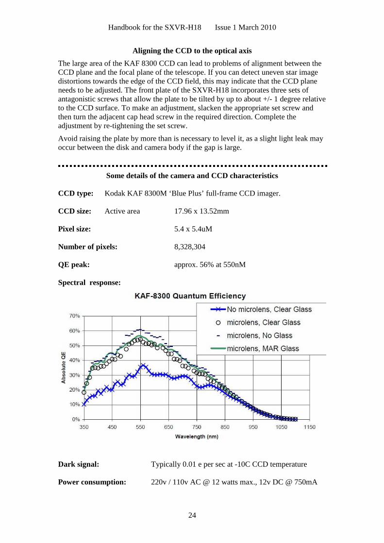
Some details of the camera and CCD characteristics
CCD type: Kodak KAF 8300M ‘Blue Plus’ full-frame CCD imager.
CCD size: Active area 17.96 x 13.52mm
Pixel size: 5.4 x 5.4uM
Number of pixels: 8,328,304
QE peak: approx. 56% at 550nM
Spectral response:
Dark signal: Typically 0.01 e per sec at -10C CCD temperature
Power consumption: 220v / 110v AC @ 12 watts max., 12v DC @ 750mA

Handbook for the SXVR-H18 Issue 1 March 2010
25
Dear User,
Thank you for purchasing a Starlight Xpress CCD Imaging System. We are confident that you will gainmuch satisfaction from this equipment, but please read carefully the accompanying instruction manualto ensure that you achieve the best performance that is capable of providing.
As with most sophisticated equipment a certain amount of routine maintenance is necessary to keep theequipment operating at its optimum performance. The maintenance has been kept to a minimum, and isfully described in the manual.
In the unfortunate instance when the equipment does not perform as expected, may we recommend thatyou first study the fault finding information supplied. If this does not remedy the problem, then contactStarlight Xpress for further advice. Our message board service on the Starlight Xpress web site willoften provide solutions to any problems.
The equipment is covered by a 12-month guarantee covering faulty design, material or workmanship inaddition to any statutory Consumer Rights of Purchasers.
CONDITIONS OF GUARANTEE
1) The equipment shall only be used for normal purposes described in the standard operatinginstructions, and within the relevant safety standards of the country where the equipment is used.
2) Repairs under guarantee will be free of charge providing proof of purchase is produced, and that theequipment is returned to the Service Agent at the Purchaser’s expense and risk, and that the equipmentproves to be defective.
3) The guarantee shall not apply to equipment damaged by fire, accident, wear an tear, misuse,unauthorised repairs, or modified in any way whatsoever, or damage suffered in transit to or from thePurchaser.
4) The Purchaser’s sole and exclusive rights under this guarantee is for repair, or at our discretion thereplacement of the equipment or any part thereof, and no remedy to consequential loss or damagewhatsoever.
5) This guarantee shall not apply to components that have a naturally limited life.
6) Starlight Xpress’s decision in all matters is final, and any faulty component which has been replacedwill become the property of Starlight Xpress Ltd.
For further info. or advice, please call:
Mr Michael Hattey,
Starlight Xpress Ltd.,
The Office, Foxley Green Farm,
Ascot Road, Holyport,
Berkshire,
England. SL6 3LA
Tel: 01628 777126
Fax: 01628 580411
e-mail: [email protected]
Web site: http://www.starlight-xpress.co.uk