Embed Size (px)
Citation preview
4、Fuel Injection System
4-1
1. EFI Mechanism Illustration…………………….…..4-2
2. The Fuel Injection System Introduction……………………....4-3
3. Electronical Fuel Injection Components & Operation Principle Introduction………………………4-3
4. Precautions In Operation……….4-5
5. Trouble Diagnosis……………….4-6
6. Components Description Of EFI……………………………….4-10
7. Fuel Lines……………………….4-13
8. Ignition System…………………4-13
9. Crankshaft position sensor……4-15
10. Temperature sensor……………4-16
11. Air By-Pass Valve………………4-17
12. O2 Sensor………………………4-18
13. Fuel Tank………………………..4-19
14. Fuel Pressure Control Valve….4-20
15. Air Cleaner……………………..4-21
16. Trouble Diagnosis & Solutions Of EFI………………………………4-22
17. Error Code Message and Solution Operation………………………4-23
18.EFI Component Malfunction Check& Replacement Procedure (PI Engine) …………………………...4-41
Ignition Coil
Fuel
Injector
Data Scan
Error indicator
Battery
Fuel Tank
Fuel Pump and Pressure Valve
Vacuum
Tube
Air-By-Pass
Valve
Crankshaft position sensor
Engine Temp. Sensor
Intake temp and pressure sensor (T-MAP)
Throttle Position Sensor (TPS)
ECU
O2 Sensor
4、Fuel Injection System
4-2
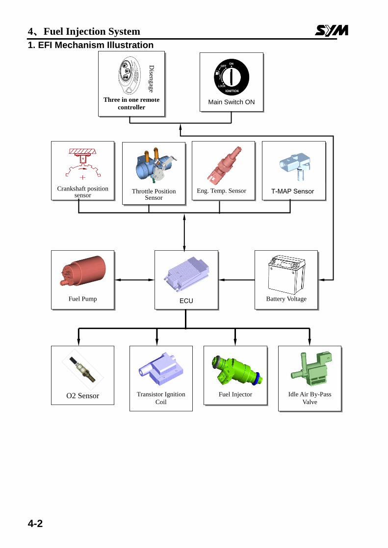
1. EFI Mechanism Illustration
Fuel Injector
Crankshaft position sensor
Throttle Position Sensor
Eng. Temp. Sensor
T-MAP Sensor
Fuel Pump
Transistor Ignition
Coil
ECU
Idle Air By-Pass
Valve
Battery Voltage
Main Switch ON Three in one remote
controller
Disen
gag
e
O2 Sensor
4、Fuel Injection System
4-3
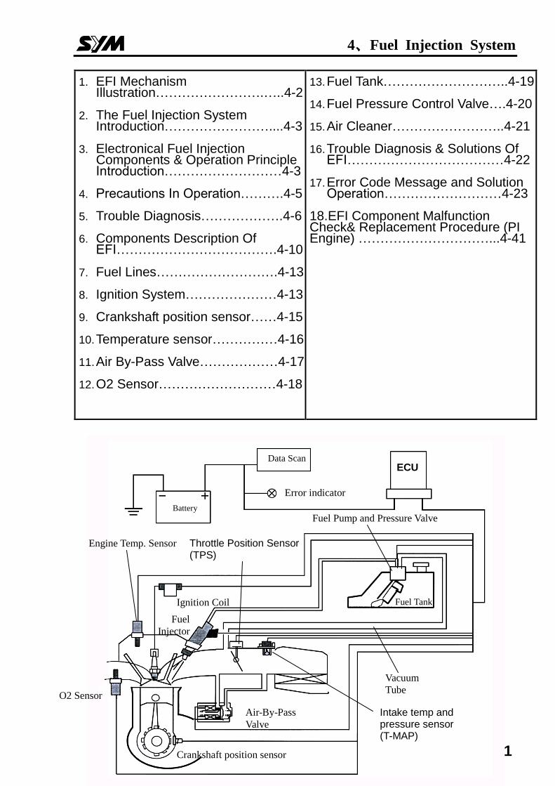
2. The Fuel Injection System Introduction Based on 4-stroke SOHC engine, displacement 125 c.c. Electronically controlled fuel injection, fuel vapor absorbed by carbon canisters. The engine burns off the blow-by fuel-gas in the crankcase through the fuel-air separating device. The O2 sensor enhances the efficiency of the catalyzer, by dynamically controlling the Fuel/Air ratio.
Electronic Fuel Injection Device
Consisting of fuel supply devices: fuel tank, fuel pump, filter, and pressure regulating valve. And fuel controller devices: fuel injector, and ECU. The fuel is pumped from electrical fuel pump in the fuel tank, to the injector on the inlet pipe. The pressure-regulating valve keeps the pressure around 2.5bar. The signals from ECU enable the injector to spray fuel into the combusting chamber once each two crankshaft-revolutions. The excessive fuel flows back to the fuel tank through the pressure-regulating valve. Fuel pump is placed within the tank to reduce the working noise, and the complicity of fuel pipes. Electrically controlled ignition and injection system effectively reduce fuel consumption rate and pollution. In traditional gasoline engine, carburetor supplies the fuel. The process is done by engine vacuum, and the negative pressure in the carburetor mixes fuel with air. Under this condition, three major processes are done simultaneously in the carburetor: 1. Air quantity measurement. 2. The determination of fuel quantity. 3. Mix of fuel and air. Electric Fuel Injection System separates the three major processes into three different devices: 1. T-MAP gauges the air quantity and temperature and sends the signal to ECU as a reference. 2. ECU decides the amount of fuel to be injected, according to the default A/F rate. 3. ECU enables the injector to spray appropriate fuel amount. The independence of these three functions will raise the accuracy of the whole process.
Our EFI engine uses computer-programmed fuel injection,the main features are:
1﹒ The quantity of fuel injected is decided according the condition of the engine. The
engine RPM, and throttle position determines the fuel quantity and injection time-length. This throttle-controlled fuel injection is better responding and more accurate.
2﹒ The quantity of fuel injection, and the determination of injection time length, are all
controlled by 8 bit microcomputer.
3﹒ The pressure regulating valve maintains a 2.5 bar pressure difference between inlet
pipe and fuel pipe, raising the accuracy of fuel injection.
4﹒ By measuring the air pressure of inlet pipe, this system gives the vehicle better
accommodation to the environment.
5﹒ Idle air by-pass system supplies fuel and air to stabilize the idle running, and cold
starting.
6﹒ O2 sensor feeds back the signal to minimize the exhaust pollution.
3. Electronic Fuel Injection Components & Operation Principle Introduction Electronic Fuel injection system consists of fuel supply devices: fuel tank, fuel pump, filter, and pressure regulating valve, and fuel controller devices: fuel injector, and ECU.
The fuel is pumped from electrical fuel pump in the fuel tank, to the injector on the inlet pipe. The pressure-regulating valve keeps the pressure around 2.5bar.
4、Fuel Injection System
4-4
The signals from ECU enable the injector to spray fuel into the combusting chamber once each two crankshaft-revolutions. The excessive fuel flows back to the fuel tank through the pressure-regulating valve. Fuel pump is placed within the tank to reduce the working noise, and the complicity of fuel pipes.
As a whole, electrically controlled ignition and fuel injection system effectively
reduce fuel consumption rate and exhaust pollution. The design is better environmental friendly.
4、Fuel Injection System
4-5
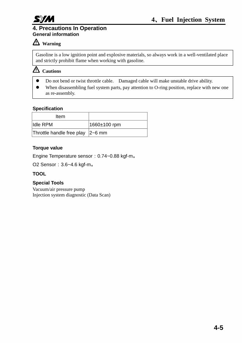
4. Precautions In Operation General information
Warning
Cautions
Specification
Item
Idle RPM 1660±100 rpm
Throttle handle free play 2~6 mm
Torque value
Engine Temperature sensor:0.74~0.88 kgf-m。
O2 Sensor:3.6~4.6 kgf-m。
TOOL
Special Tools
Vacuum/air pressure pump
Injection system diagnostic (Data Scan)
Gasoline is a low ignition point and explosive materials, so always work in a well-ventilated place
and strictly prohibit flame when working with gasoline.
Do not bend or twist throttle cable. Damaged cable will make unstable drive ability.
When disassembling fuel system parts, pay attention to O-ring position, replace with new one
as re-assembly.
4、Fuel Injection System
4-6
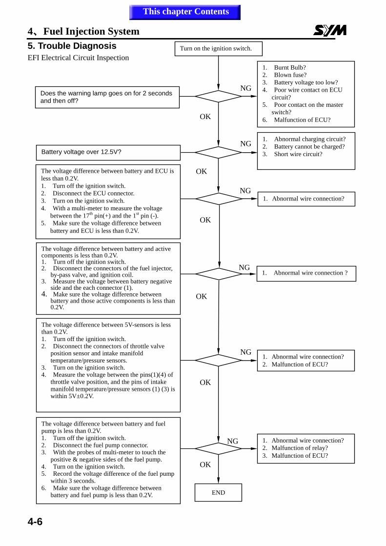
5. Trouble Diagnosis
EFI Electrical Circuit Inspection
Turn on the ignition switch.
NG
NG
OK
OK
OK
OK
OK
NG
NG
NG
NG
OK
Does the warning lamp goes on for 2 seconds and then off?
Battery voltage over 12.5V?
The voltage difference between battery and ECU is
less than 0.2V.
1. Turn off the ignition switch.
2. Disconnect the ECU connector.
3. Turn on the ignition switch.
4. With a multi-meter to measure the voltage
between the 17th
pin(+) and the 1st pin (-).
5. Make sure the voltage difference between
battery and ECU is less than 0.2V.
The voltage difference between battery and active components is less than 0.2V. 1. Turn off the ignition switch. 2. Disconnect the connectors of the fuel injector,
by-pass valve, and ignition coil. 3. Measure the voltage between battery negative
side and the each connector (1). 4. Make sure the voltage difference between
battery and those active components is less than 0.2V.
The voltage difference between 5V-sensors is less than 0.2V. 1. Turn off the ignition switch. 2. Disconnect the connectors of throttle valve
position sensor and intake manifold temperature/pressure sensors.
3. Turn on the ignition switch. 4. Measure the voltage between the pins(1)(4) of
throttle valve position, and the pins of intake manifold temperature/pressure sensors (1) (3) is within 5V±0.2V.
The voltage difference between battery and fuel pump is less than 0.2V. 1. Turn off the ignition switch. 2. Disconnect the fuel pump connector. 3. With the probes of multi-meter to touch the
positive & negative sides of the fuel pump. 4. Turn on the ignition switch. 5. Record the voltage difference of the fuel pump
within 3 seconds. 6. Make sure the voltage difference between
battery and fuel pump is less than 0.2V.
1. Burnt Bulb?
2. Blown fuse?
3. Battery voltage too low?
4. Poor wire contact on ECU
circuit?
5. Poor contact on the master
switch?
6. Malfunction of ECU?
1. Abnormal charging circuit?
2. Battery cannot be charged?
3. Short wire circuit?
1. Abnormal wire connection?
1. Abnormal wire connection ?
1. Abnormal wire connection?
2. Malfunction of ECU?
1. Abnormal wire connection?
2. Malfunction of relay?
3. Malfunction of ECU?
END
This chapter Contents
4、Fuel Injection System
4-7
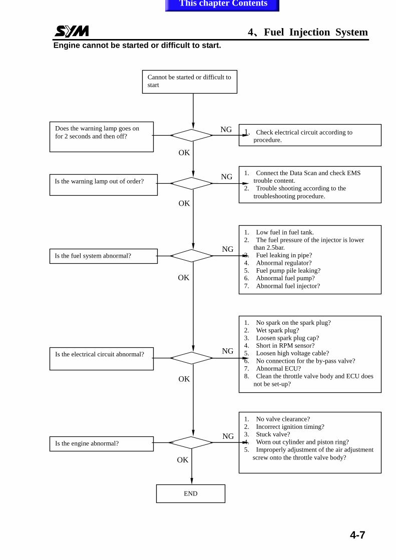
Engine cannot be started or difficult to start.
OK
NG
Does the warning lamp goes on
for 2 seconds and then off?
Is the warning lamp out of order?
Is the fuel system abnormal?
Is the electrical circuit abnormal?
Is the engine abnormal?
Cannot be started or difficult to
start
1. Check electrical circuit according to
procedure.
1. Connect the Data Scan and check EMS
trouble content.
2. Trouble shooting according to the
troubleshooting procedure.
1. Low fuel in fuel tank.
2. The fuel pressure of the injector is lower
than 2.5bar.
3. Fuel leaking in pipe?
4. Abnormal regulator?
5. Fuel pump pile leaking?
6. Abnormal fuel pump?
7. Abnormal fuel injector?
1. No spark on the spark plug?
2. Wet spark plug?
3. Loosen spark plug cap?
4. Short in RPM sensor?
5. Loosen high voltage cable?
6. No connection for the by-pass valve?
7. Abnormal ECU?
8. Clean the throttle valve body and ECU does
not be set-up?
1. No valve clearance?
2. Incorrect ignition timing?
3. Stuck valve?
4. Worn out cylinder and piston ring?
5. Improperly adjustment of the air adjustment
screw onto the throttle valve body?
END
OK
NG
OK
NG
OK
NG
OK
NG
This chapter Contents
4、Fuel Injection System
4-8
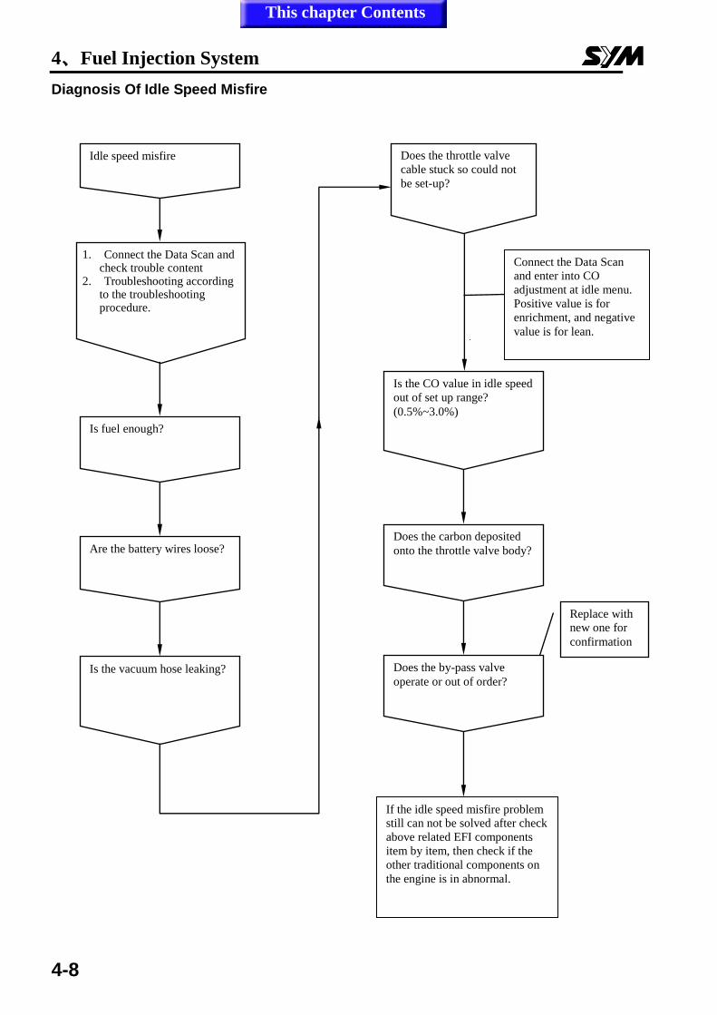
Diagnosis Of Idle Speed Misfire
接上診斷器,進入
怠速CO調整畫面
正值增濃
負值調稀
Does the by-pass valve
operate or out of order?
Connect the Data Scan
and enter into CO
adjustment at idle menu.
Positive value is for
enrichment, and negative
value is for lean.
If the idle speed misfire problem
still can not be solved after check
above related EFI components
item by item, then check if the
other traditional components on
the engine is in abnormal.
Replace with
new one for
confirmation
Idle speed misfire
1. Connect the Data Scan and check trouble content
2. Troubleshooting according to the troubleshooting procedure.
Is fuel enough?
Are the battery wires loose?
Is the vacuum hose leaking?
Does the throttle valve
cable stuck so could not
be set-up?
Is the CO value in idle speed
out of set up range?
(0.5%~3.0%)
Does the carbon deposited
onto the throttle valve body?
This chapter Contents
4、Fuel Injection System
4-9
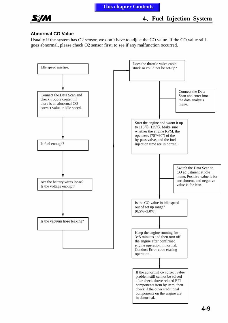
Abnormal CO Value
Usually if the system has O2 sensor, we don’t have to adjust the CO value. If the CO value still
goes abnormal, please check O2 sensor first, to see if any malfunction occurred.
Connect the Data Scan and enter into the data analysis menu.
If the abnormal co correct value problem still cannot be solved after check above related EFI components item by item, then check if the other traditional components on the engine are in abnormal.
Switch the Data Scan to CO adjustment at idle menu. Positive value is for enrichment, and negative value is for lean.
Idle speed misfire.
Connect the Data Scan and check trouble content if there is an abnormal CO correct value in idle speed.
Is fuel enough?
Are the battery wires loose? Is the voltage enough?
Is the vacuum hose leaking?
Does the throttle valve cable stuck so could not be set-up?
Start the engine and warm it up to 115℃~125℃. Make sure whether the engine RPM, the openness (75º~90º) of the by-pass valve, and the fuel injection time are in normal.
Is the CO value in idle speed out of set up range? (0.5%~3.0%)
Keep the engine running for 3~5 minutes and then turn off the engine after confirmed engine operation in normal. Conduct Error code erasing operation.
This chapter Contents
4、Fuel Injection System
4-10
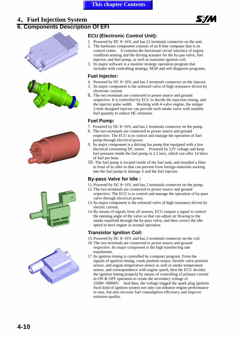
6. Components Description Of EFI
ECU (Electronic Control Unit): 1. Powered by DC 8~16V, and has 22 terminals connector on the unit. 2. The hardware component consists of an 8-bite computer that is its
control center. It contains the functional circuit interface of engine condition sensing and the driving actuator for the by-pas valve, fuel injector, and fuel pump, as well as transistor ignition coil.
3. Its major software is a monitor strategy operation program that includes with controlling strategy, MAP and self-diagnosis programs.
Fuel Injector: 4. Powered by DC 8~16V, and has 2 terminals connector on the injector. 5. Its major component is the solenoid valve of high resistance driven by
electronic current. 6. The two terminals are connected to power source and ground
respective. It is controlled by ECU to decide the injection timing, and the injector pulse width. Working with 4-valve engine, the unique 2-hole designed injector can provide each intake valve with suitable fuel quantity to reduce HC emission.
Fuel Pump: 7. Powered by DC 8~16V, and has 2 terminals connector on the pump. 8. The two terminals are connected to power source and ground
respective. The ECU is to control and manage the operation of fuel pump through electrical power.
9. Its major component is a driving fan pump that equipped with a low electrical consuming DC motor. Powered by 12V voltage and keep fuel pressure inside the fuel pump in 2.5 bars, which can offer 14 liters of fuel per hour.
10. The fuel pump is located inside of the fuel tank, and installed a filter in front of its inlet so that can prevent from foreign materials sucking into the fuel pump to damage it and the fuel injector.
By-pass Valve for Idle : 11. Powered by DC 8~16V, and has 2 terminals connector on the pump. 12. The two terminals are connected to power source and ground
respective. The ECU is to control and manage the operation of by-pass valve through electrical power.
13. Its major component is the solenoid valve of high resistance driven by electric current.
14. By means of signals from all sensors, ECU outputs a signal to control the opening angle of the valve so that can adjust air flowing to the intake manifold through the by-pass valve, and then correct the idle speed to have engine in normal operation.
Transistor Ignition Coil: 15. Powered by DC 8~16V, and has 2 terminals connector on the coil. 16. The two terminals are connected to power source and ground
respective. Its major component is the high transferring rate transformer.
17. Its ignition timing is controlled by computer program. From the signals of ignition timing, crank position sensor, throttle valve position sensor, and engine temperature sensor as well as intake temperature sensor, and correspondence with engine speed, then the ECU decides the ignition timing properly by means of controlling of primary current in ON & OFF operation to create the secondary voltage of 25000~30000V. And then, the voltage trigged the spark plug ignition. Such kind of ignition system not only can enhance engine performance to max. but also increase fuel consumption efficiency and improve emission quality.
This chapter Contents
4、Fuel Injection System
4-11
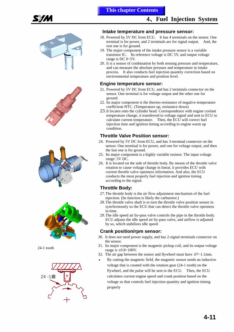
Intake temperature and pressure sensor: 18. Powered by 5V DC from ECU. It has 4 terminals on the sensor. One
terminal is for power, and 2 terminals are for signal output. And, the rest one is for ground.
19. The major component of the intake pressure sensor is a variable transistor IC. Its reference voltage is DC 5V, and output voltage range is DC 0~5V.
20. It is a sensor of combination by both sensing pressure and temperature, and can measure the absolute pressure and temperature in intake process. It also conducts fuel injection quantity correction based on environmental temperature and position level.
Engine temperature sensor: 21. Powered by 5V DC from ECU, and has 2 terminals connector on the
sensor. One terminal is for voltage output and the other one for ground.
22. Its major component is the thermo-resistance of negative temperature coefficient-NTC. (Temperature up, resistance down)
23. It locates onto the cylinder head. Correspondence with engine coolant temperature change, it transferred to voltage signal and sent to ECU to calculate current temperature. Then, the ECU will correct fuel injection time and ignition timing according to engine warm up condition.
Throttle Valve Position sensor: 24. Powered by 5V DC from ECU, and has 3-terminal connector on the
sensor. One terminal is for power, and one for voltage output, and then the last one is for ground.
25. Its major component is a highly variable resistor. The input voltage range: 5V DC.
26. It is located on the side of throttle body. By means of the throttle valve rotation to cause voltage change in linear, it provides ECU with current throttle valve openness information. And also, the ECU conducts the most properly fuel injection and ignition timing according to the signal.
Throttle Body: 27. The throttle body is the air flow adjustment mechanism of the fuel
injection. (Its function is likely the carburetor.) 28. The throttle valve shaft is to turn the throttle valve position sensor in
synchronously so the ECU that can detect the throttle valve openness in time.
29. The idle speed air by-pass valve controls the pipe in the throttle body. ECU adjusts the idle speed air by-pass valve, and airflow is adjusted by so, which stabilizes idle speed.
Crank position/rpm sensor: 30. It does not need power supply, and has 2-signal terminals connector on
the sensor. 31. Its major component is the magnetic pickup coil, and its output voltage
range is ±0.8~100V. 32. The air gap between the sensor and flywheel must have .07~1.1mm.
By cutting the magnetic field, the magnetic sensor sends an inductive
voltage that is created with the rotation gear (24-1 tooth) on the
flywheel, and the pulse will be sent to the ECU. Then, the ECU
calculates current engine speed and crank position based on the
voltage so that controls fuel injection quantity and ignition timing
properly
24 -1齒24 -1齒
24-1 tooth
This chapter Contents
4、Fuel Injection System
4-12
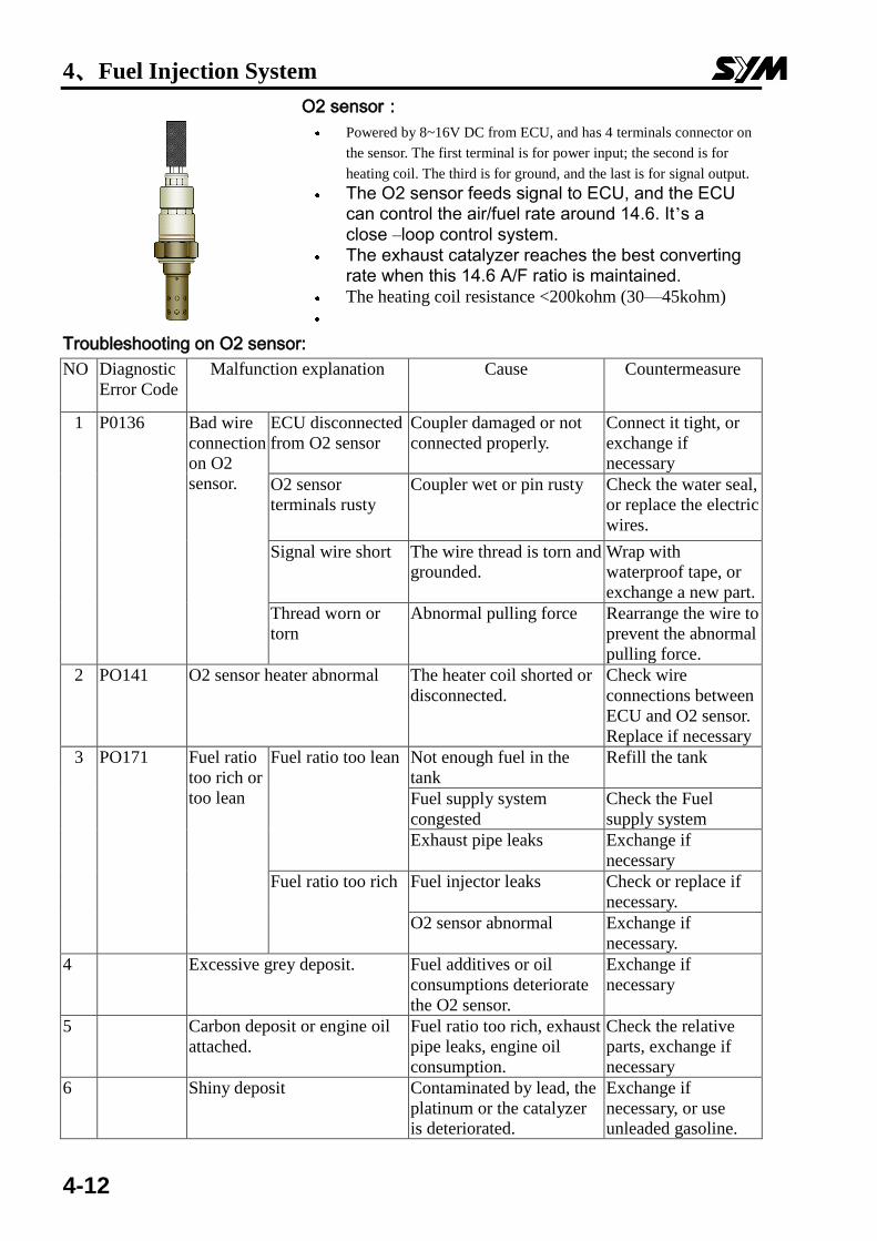
O2 sensor:
Powered by 8~16V DC from ECU, and has 4 terminals connector on
the sensor. The first terminal is for power input; the second is for
heating coil. The third is for ground, and the last is for signal output. The O2 sensor feeds signal to ECU, and the ECU
can control the air/fuel rate around 14.6. It’s a close –loop control system.
The exhaust catalyzer reaches the best converting rate when this 14.6 A/F ratio is maintained.
The heating coil resistance <200kohm (30—45kohm)
Troubleshooting on O2 sensor:
NO Diagnostic
Error Code
Malfunction explanation Cause Countermeasure
1 P0136 Bad wire
connection
on O2
sensor.
ECU disconnected
from O2 sensor
Coupler damaged or not
connected properly.
Connect it tight, or
exchange if
necessary
O2 sensor
terminals rusty
Coupler wet or pin rusty Check the water seal,
or replace the electric
wires.
Signal wire short The wire thread is torn and
grounded.
Wrap with
waterproof tape, or
exchange a new part.
Thread worn or
torn
Abnormal pulling force Rearrange the wire to
prevent the abnormal
pulling force.
2 PO141 O2 sensor heater abnormal The heater coil shorted or
disconnected.
Check wire
connections between
ECU and O2 sensor.
Replace if necessary
3 PO171 Fuel ratio
too rich or
too lean
Fuel ratio too lean Not enough fuel in the
tank
Refill the tank
Fuel supply system
congested
Check the Fuel
supply system
Exhaust pipe leaks Exchange if
necessary
Fuel ratio too rich Fuel injector leaks Check or replace if
necessary.
O2 sensor abnormal Exchange if
necessary.
4 Excessive grey deposit. Fuel additives or oil
consumptions deteriorate
the O2 sensor.
Exchange if
necessary
5 Carbon deposit or engine oil
attached.
Fuel ratio too rich, exhaust
pipe leaks, engine oil
consumption.
Check the relative
parts, exchange if
necessary
6 Shiny deposit Contaminated by lead, the
platinum or the catalyzer
is deteriorated.
Exchange if
necessary, or use
unleaded gasoline.
4、Fuel Injection System
4-13
7. Fuel Lines
System Description:
1. After key-on, all sensors’ signals sent to the ECU first. The electrical fuel pump will be
activated by ECU signal. If the engine did not start for 2~3 seconds, then the fuel pump will
be turned off to save electricity. The pressure regulator maintains the fuel pressure around
2.5bar, and the fuel injector spray proper fuel quantity according to the conditions and
environmental coefficient. When key-off or engine stopped, the fuel pumps stop operating.
2. The fuel filter is to filter alien materials so it has to be replaced regularly.
3. Do not let the starting motor keep running when the engine cannot start. It will cause battery
voltage to decrease. If the voltage drops under 8V, the pump will not operate. The
countermeasure will be starting the engine by connecting a new battery or with kick-starter.
Injector
The double-hole injector provides each intake valve a fuel jet. This can reduce the pollution of HC. The shortened version of fuel pump plate makes its size more compact, and sturdier against shocks. ECU signal controls the regulator to maintain 2.5 bars between the fuel pressure and the air pressure of inlet pipe. Through controlling the time length of injection under steady fuel pressure, the system can optimize the fuel injection quantity according to different engine workloads.
Fuel Pump
Electrical fuel pump is mounted inside the fuel tank. The power source is DC current provided and controlled by ECU; the pump can provide 14L/hour under the pressure of 2.5 bars.
Battery
ECU
Fuel filter
Fuel injector Fuel tank
Vacuum hose
Fuel pump & pressure regulator
This chapter Contents
4、Fuel Injection System
4-14
8. Ignition System
1. Principle of operation:
The engine is equipped with a computerized ignition control system that collects signals
from TDC/crankshaft position sensor; throttle position sensor, temperature sensor, and intake
temperature as well as pressure sensor. Then, correspondence with engine RPM, this 8-bite
microcomputer in the system controls ignition timing properly. The secondary coil creates
25000~30000V high voltage to ignite the spark plug by means of the transistor operation of
the primary current entry from the ECU. This can maximize engine performance and also
decrease fuel consumption.
三﹒ Specification
1. Ignition timing: BTDC 5~13°/1600RPM
2. Spark plug: NGK CR7E
Gap: 0.8mm 3. A.C.G. Pulse generator coil:
120+10% Ω (G/W-LY)
4. Ignition coil:
Primary circuit: 0.63 ± 0.03 Ω (20℃)
5. Battery:TTZ10S 8.6Ah
Capacity:12 v 8.6Ah
ACG/flywheel gear
ring (24-1 tooth)
TDC/ crank
position sensor
Throttle valve openness Intake temperature/pressure
Engine temperature
RPM/TD
C
Diode
Ignition coil
Spark
plu
g
ECU
This chapter Contents
4、Fuel Injection System
4-15
9. Crank Position Sensor The magnetic field type sensor generates a
voltage signal to calculate engine speed with
ACG gear ring (24-1 tooth).
There is one tooth in every 15 degree on the
gear ring. But, one of the teeth is blank for
the TDC calculating base.
Description:
ECU receives all sensors’ signals to control the throttle valve openness with PWM, and adjust
airflow through the by-pass valve of the intake manifold. It can adjust idle speed for a stably
running engine.
1. When engine cold starting---the by-pass valve open for a while to increase airflow and to
stabilize engine idle speed within initial starting.
2. Warm-up---when engine oil is in low temperature condition, the by-pass valve adjusts airflow
according to engine temperature (engine oil temperature), and raises idle speed.
3. Speed decreasing--- ECU controls the by-pass valve in correspondence with throttle
operation, to provide inlet pipe with proper airflow quantity. Such operation will smooth
the engine rpm reduction process, preventing the engine from stalling, excessive negative
pressure, and also reduce HC emission.
ECU Signal
Secondary
voltage
Sensor signal Time flow
TDC TDC
Closed
Ignition
Flywheel
gear ring
No teeth
This chapter Contents
4、Fuel Injection System
4-16
10. Temperature Sensors Engine oil temperature sensor: According to the semiconductor’s characteristic, the sensor detects
the temperature of engine oil and metal parts and then send a voltage signal to
the ECU. On this base, the ECU can correct fuel injection and ignition timing.
Intake temperature and pressure sensor: Sensor combined both pressure and NTC can detect the
absolute pressure and temperature in the intake manifold, and then
provides the ECU with signal for adjustment fuel injection quantity
based on environmental temperature and air pressure difference from
elevation level change.
Engine temperature sensor
Intake temperature and
pressure sensor
ECU
NTC-Negative Temperature Coefficient Resistor
4、Fuel Injection System
4-17
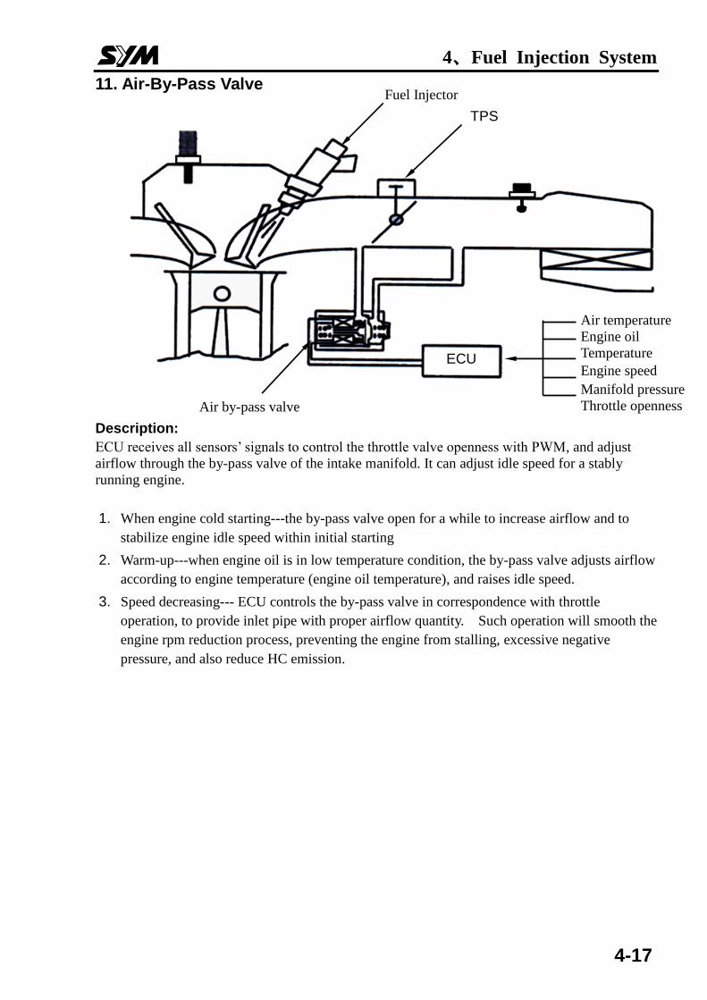
11. Air-By-Pass Valve
Description:
ECU receives all sensors’ signals to control the throttle valve openness with PWM, and adjust
airflow through the by-pass valve of the intake manifold. It can adjust idle speed for a stably
running engine.
1. When engine cold starting---the by-pass valve open for a while to increase airflow and to
stabilize engine idle speed within initial starting
2. Warm-up---when engine oil is in low temperature condition, the by-pass valve adjusts airflow
according to engine temperature (engine oil temperature), and raises idle speed.
3. Speed decreasing--- ECU controls the by-pass valve in correspondence with throttle
operation, to provide inlet pipe with proper airflow quantity. Such operation will smooth the
engine rpm reduction process, preventing the engine from stalling, excessive negative
pressure, and also reduce HC emission.
ECU
Fuel Injector
TPS
Air by-pass valve
Air temperature
Engine oil
Temperature
Engine speed
Manifold pressure
Throttle openness
4、Fuel Injection System
4-18
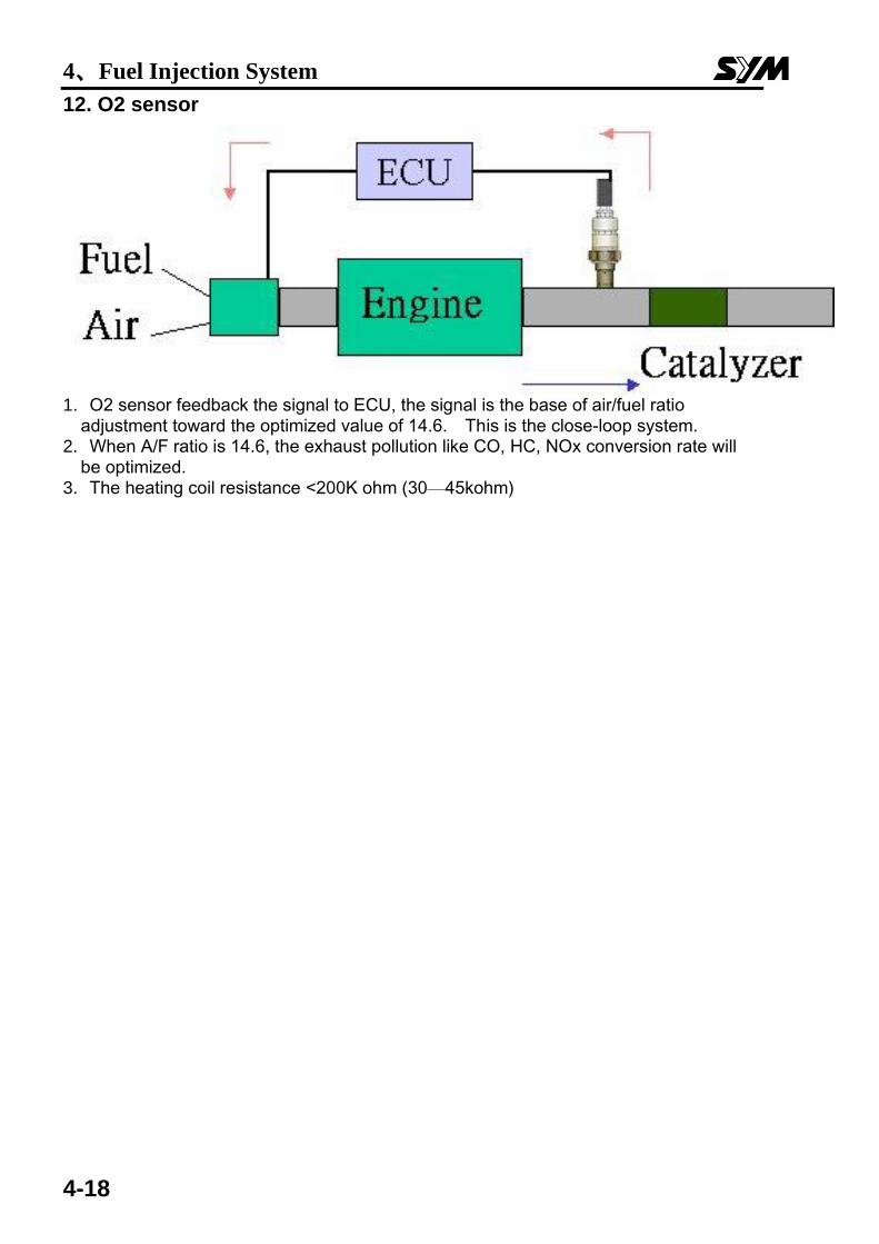
12. O2 sensor
1. O2 sensor feedback the signal to ECU, the signal is the base of air/fuel ratio
adjustment toward the optimized value of 14.6. This is the close-loop system. 2. When A/F ratio is 14.6, the exhaust pollution like CO, HC, NOx conversion rate will
be optimized. 3. The heating coil resistance <200K ohm (30—45kohm)
4、Fuel Injection System
4-19
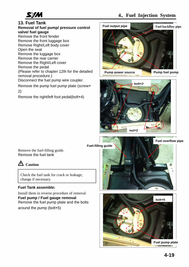
13. Fuel Tank Removal of fuel pump/ pressure control valve/ fuel gauge Remove the front fender Remove the front luggage box Remove Right/Left body cover Open the seat Remove the luggage box Remove the rear carrier Remove the Right/Left cover Remove the pedal (Please refer to chapter 12th for the detailed removal procedure.) Disconnect the fuel pump wire coupler.
Remove the pump fuel pump plate (screw×
2)
Remove the right/left foot pedal(bolt×4)
Remove the fuel-filling guide.
Remove the fuel tank
Caution
Fuel Tank assemble:
Install them in reverse procedure of removal
Fuel pump / Fuel gauge removal Remove the fuel pump plate and the bolts
around the pump (bolt×5)
bolt×2
nut×2
Fuel output pipe
Pump power source Pump fuel pump plate
Fuel overflow pipe
溢油管 Fuel-filling guide
bolt×5
Fuel pump plate
Check the fuel tank for crack or leakage;
change if necessary.
Fuel backflow pipe
4、Fuel Injection System
4-20
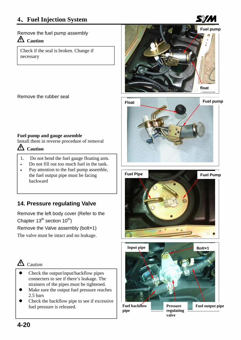
Remove the fuel pump assembly
Caution
Remove the rubber seal Fuel pump and gauge assemble Install them in reverse procedure of removal
Caution
14. Pressure regulating Valve
Remove the left body cover (Refer to the
Chapter 13th section 10th)
Remove the Valve assembly (bolt×1)
The valve must be intact and no leakage.
Caution
Check if the seal is broken. Change if
necessary
1. Do not bend the fuel gauge floating arm.
Do not fill out too much fuel in the tank.
Pay attention to the fuel pump assemble,
the fuel output pipe must be facing
backward
Fuel pump
燃油泵
float
Fuel pump Float
Fuel Pump Fuel Pipe
Check the output/input/backflow pipes
connecters to see if there’s leakage. The
strainers of the pipes must be tightened.
Make sure the output fuel pressure reaches
2.5 bars Check the backflow pipe to see if excessive
fuel pressure is released.
Input pipe Bolt×1
Fuel backflow
pipe
Pressure
regulating
valve
Fuel output pipe
出油管
4、Fuel Injection System
4-21
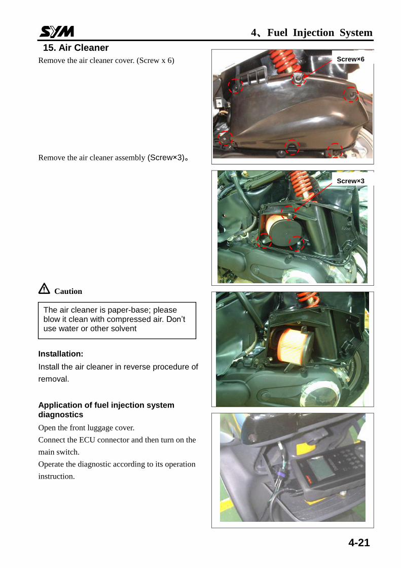
15. Air Cleaner
Remove the air cleaner cover. (Screw x 6)
Remove the air cleaner assembly (Screw×3)。
Caution
Installation:
Install the air cleaner in reverse procedure of
removal.
Application of fuel injection system diagnostics
Open the front luggage cover.
Connect the ECU connector and then turn on the
main switch.
Operate the diagnostic according to its operation
instruction.
Screw×6
Screw×3
The air cleaner is paper-base; please blow it clean with compressed air. Don’t use water or other solvent
4、Fuel Injection System
4-22
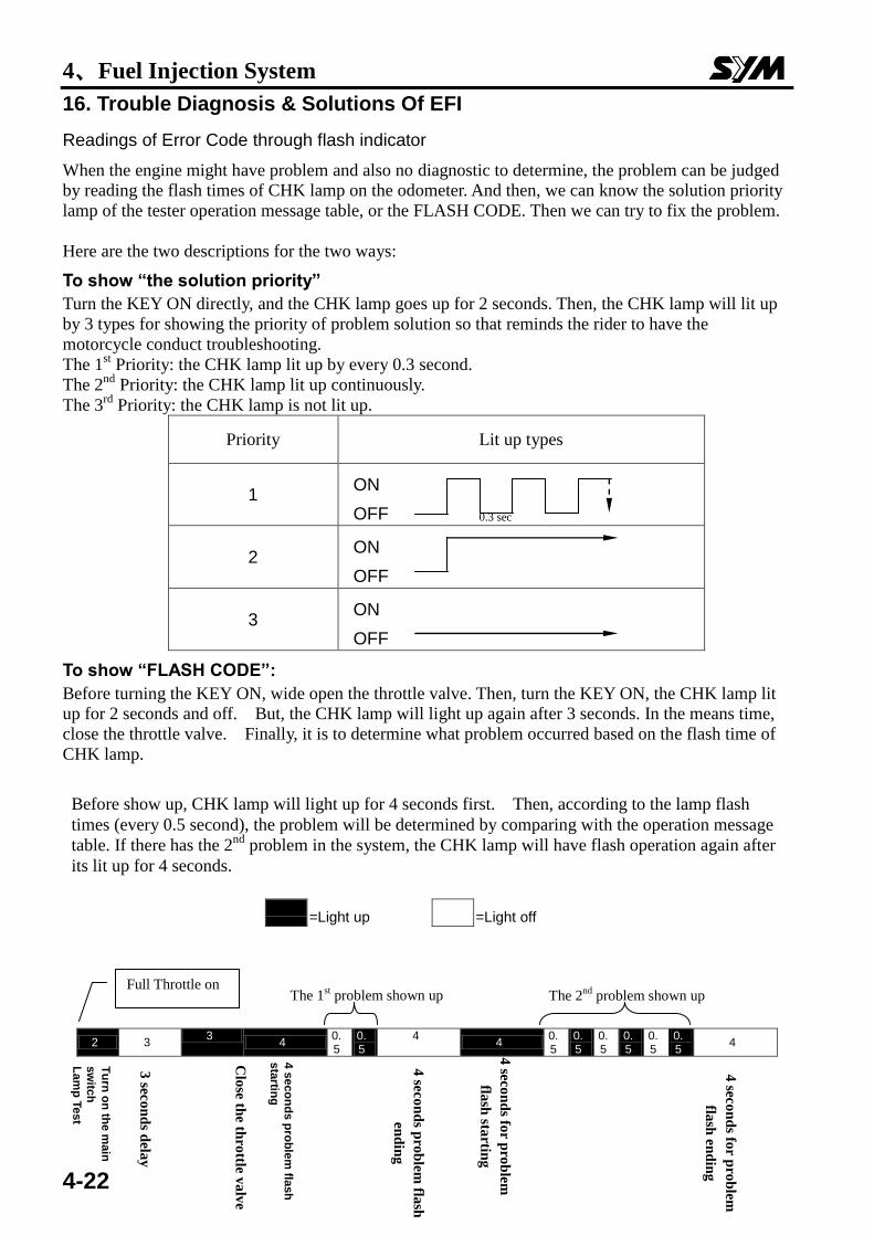
16. Trouble Diagnosis & Solutions Of EFI
Readings of Error Code through flash indicator
When the engine might have problem and also no diagnostic to determine, the problem can be judged
by reading the flash times of CHK lamp on the odometer. And then, we can know the solution priority
lamp of the tester operation message table, or the FLASH CODE. Then we can try to fix the problem.
Here are the two descriptions for the two ways:
To show “the solution priority”
Turn the KEY ON directly, and the CHK lamp goes up for 2 seconds. Then, the CHK lamp will lit up
by 3 types for showing the priority of problem solution so that reminds the rider to have the
motorcycle conduct troubleshooting.
The 1st Priority: the CHK lamp lit up by every 0.3 second.
The 2nd
Priority: the CHK lamp lit up continuously.
The 3rd
Priority: the CHK lamp is not lit up.
Priority Lit up types
1 ON
OFF
2 ON
OFF
3 ON
OFF
To show “FLASH CODE”:
Before turning the KEY ON, wide open the throttle valve. Then, turn the KEY ON, the CHK lamp lit
up for 2 seconds and off. But, the CHK lamp will light up again after 3 seconds. In the means time,
close the throttle valve. Finally, it is to determine what problem occurred based on the flash time of
CHK lamp.
Before show up, CHK lamp will light up for 4 seconds first. Then, according to the lamp flash
times (every 0.5 second), the problem will be determined by comparing with the operation message
table. If there has the 2nd
problem in the system, the CHK lamp will have flash operation again after
its lit up for 4 seconds.
=Light up
=Light off
2 3 3
4 0.5
0.5
4 4
0.5
0.5
0.5
0.5
0.5
0.5
4
0.3 sec
The 1st problem shown up The 2
nd problem shown up
Tu
rn o
n th
e m
ain
sw
itch
La
mp
Test
3 sec
on
ds d
elay
Clo
se the th
rottle v
alv
e
4 s
eco
nd
s p
rob
lem
flash
sta
rting
始
4 sec
on
ds p
rob
lem fla
sh
end
ing
4 sec
on
ds fo
r pro
blem
flash
startin
g
4 sec
on
ds fo
r pro
blem
flash
end
ing
Full Throttle on
4、Fuel Injection System
4-23
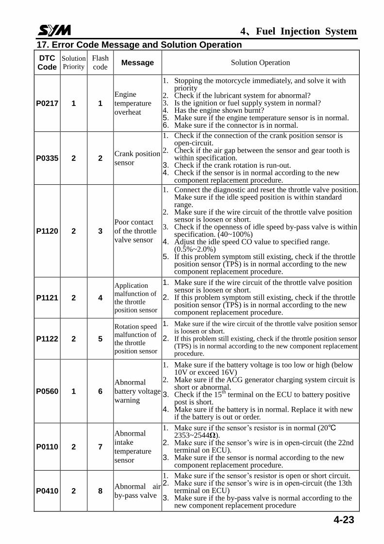
17. Error Code Message and Solution Operation
DTC Code
Solution
Priority Flash
code Message Solution Operation
P0217 1 1
Engine
temperature
overheat
1. Stopping the motorcycle immediately, and solve it with priority
2. Check if the lubricant system for abnormal? 3. Is the ignition or fuel supply system in normal? 4. Has the engine shown burnt? 5. Make sure if the engine temperature sensor is in normal. 6. Make sure if the connector is in normal.
P0335 2 2 Crank position
sensor
1. Check if the connection of the crank position sensor is open-circuit.
2. Check if the air gap between the sensor and gear tooth is within specification.
3. Check if the crank rotation is run-out. 4. Check if the sensor is in normal according to the new
component replacement procedure.
P1120 2 3
Poor contact
of the throttle
valve sensor
1. Connect the diagnostic and reset the throttle valve position. Make sure if the idle speed position is within standard range.
2. Make sure if the wire circuit of the throttle valve position sensor is loosen or short.
3. Check if the openness of idle speed by-pass valve is within specification. (40~100%)
4. Adjust the idle speed CO value to specified range. (0.5%~2.0%)
5. If this problem symptom still existing, check if the throttle position sensor (TPS) is in normal according to the new component replacement procedure.
P1121 2 4
Application
malfunction of
the throttle
position sensor
1. Make sure if the wire circuit of the throttle valve position sensor is loosen or short.
2. If this problem symptom still existing, check if the throttle position sensor (TPS) is in normal according to the new component replacement procedure.
P1122 2 5
Rotation speed
malfunction of
the throttle
position sensor
1. Make sure if the wire circuit of the throttle valve position sensor is loosen or short.
2. If this problem still existing, check if the throttle position sensor (TPS) is in normal according to the new component replacement procedure.
P0560 1 6
Abnormal
battery voltage
warning
1. Make sure if the battery voltage is too low or high (below 10V or exceed 16V)
2. Make sure if the ACG generator charging system circuit is short or abnormal.
3. Check if the 15th
terminal on the ECU to battery positive post is short.
4. Make sure if the battery is in normal. Replace it with new if the battery is out or order.
P0110 2 7
Abnormal
intake
temperature
sensor
1. Make sure if the sensor’s resistor is in normal (20℃ 2353~2544Ω).
2. Make sure if the sensor’s wire is in open-circuit (the 22nd terminal on ECU).
3. Make sure if the sensor is normal according to the new component replacement procedure.
P0410 2 8 Abnormal air
by-pass valve
1. Make sure if the sensor’s resistor is open or short circuit. 2. Make sure if the sensor’s wire is in open-circuit (the 13th
terminal on ECU) 3. Make sure if the by-pass valve is normal according to the
new component replacement procedure
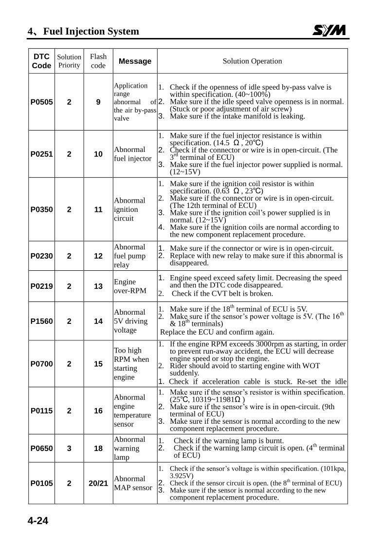
4、Fuel Injection System
4-24
DTC Code
Solution
Priority
Flash
code Message Solution Operation
P0505 2 9
Application
range
abnormal of
the air by-pass
valve
1. Check if the openness of idle speed by-pass valve is within specification. (40~100%)
2. Make sure if the idle speed valve openness is in normal. (Stuck or poor adjustment of air screw)
3. Make sure if the intake manifold is leaking.
P0251 2 10 Abnormal
fuel injector
1. Make sure if the fuel injector resistance is within specification. (14.5 Ω , 20℃)
2. Check if the connector or wire is in open-circuit. (The 3
rd terminal of ECU)
3. Make sure if the fuel injector power supplied is normal. (12~15V)
P0350 2 11
Abnormal
ignition
circuit
1. Make sure if the ignition coil resistor is within specification. (0.63 Ω , 23℃)
2. Make sure if the connector or wire is in open-circuit. (The 12th terminal of ECU)
3. Make sure if the ignition coil’s power supplied is in normal. (12~15V)
4. Make sure if the ignition coils are normal according to the new component replacement procedure.
P0230 2 12
Abnormal
fuel pump
relay
1. Make sure if the connector or wire is in open-circuit. 2. Replace with new relay to make sure if this abnormal is
disappeared.
P0219 2 13 Engine
over-RPM
1. Engine speed exceed safety limit. Decreasing the speed and then the DTC code disappeared.
2. Check if the CVT belt is broken.
P1560 2 14
Abnormal
5V driving
voltage
1. Make sure if the 18th
terminal of ECU is 5V. 2. Make sure if the sensor’s power voltage is 5V. (The 16
th
& 18th
terminals) Replace the ECU and confirm again.
P0700 2 15
Too high
RPM when
starting
engine
1. If the engine RPM exceeds 3000rpm as starting, in order to prevent run-away accident, the ECU will decrease engine speed or stop the engine.
2. Rider should avoid to starting engine with WOT suddenly.
1. Check if acceleration cable is stuck. Re-set the idle
speed adjustment position.。
P0115 2 16
Abnormal
engine
temperature
sensor
1. Make sure if the sensor’s resistor is within specification. (25℃, 10319~11981Ω )
2. Make sure if the sensor’s wire is in open-circuit. (9th terminal of ECU)
3. Make sure if the sensor is normal according to the new component replacement procedure.
P0650 3 18
Abnormal
warning
lamp
1. Check if the warning lamp is burnt. 2. Check if the warning lamp circuit is open. (4
th terminal
of ECU)
P0105 2 20/21 Abnormal
MAP sensor
1. Check if the sensor’s voltage is within specification. (101kpa, 3.925V)
2. Check if the sensor circuit is open. (the 8th terminal of ECU)
3. Make sure if the sensor is normal according to the new component replacement procedure.
4、Fuel Injection System
4-25
DTC Code
Solution
Priority
Flash
code Message Solution Operation
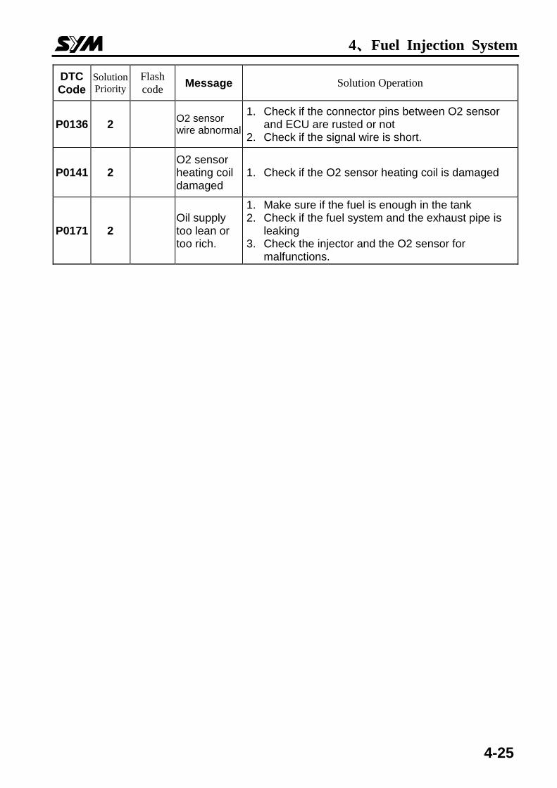
P0136 2 O2 sensor wire abnormal
1. Check if the connector pins between O2 sensor and ECU are rusted or not
2. Check if the signal wire is short.
P0141 2 O2 sensor heating coil damaged
1. Check if the O2 sensor heating coil is damaged
P0171 2 Oil supply too lean or too rich.
1. Make sure if the fuel is enough in the tank 2. Check if the fuel system and the exhaust pipe is
leaking 3. Check the injector and the O2 sensor for
malfunctions.
4、Fuel Injection System
4-26
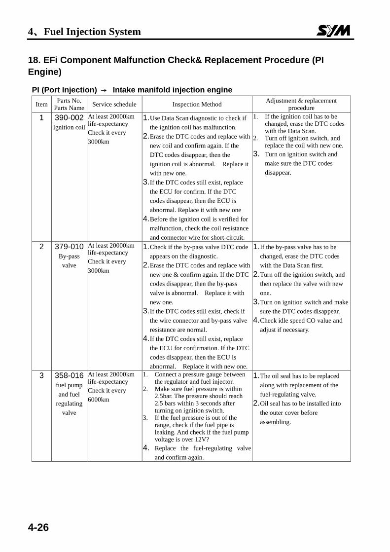
18. EFi Component Malfunction Check& Replacement Procedure (PI
Engine)
PI (Port Injection) → Intake manifold injection engine
Item Parts No.
Parts Name Service schedule Inspection Method
Adjustment & replacement procedure
1 390-002 Ignition coil
At least 20000km life-expectancy
Check it every
3000km
1. Use Data Scan diagnostic to check if
the ignition coil has malfunction. 2. Erase the DTC codes and replace with
new coil and confirm again. If the
DTC codes disappear, then the
ignition coil is abnormal. Replace it
with new one.
3. If the DTC codes still exist, replace
the ECU for confirm. If the DTC
codes disappear, then the ECU is
abnormal. Replace it with new one 4. Before the ignition coil is verified for
malfunction, check the coil resistance
and connector wire for short-circuit.
1. If the ignition coil has to be changed, erase the DTC codes with the Data Scan.
2. Turn off ignition switch, and replace the coil with new one.
3. Turn on ignition switch and
make sure the DTC codes
disappear.
2 379-010 By-pass
valve
At least 20000km life-expectancy
Check it every
3000km
1. Check if the by-pass valve DTC code
appears on the diagnostic. 2. Erase the DTC codes and replace with
new one & confirm again. If the DTC
codes disappear, then the by-pass
valve is abnormal. Replace it with
new one. 3. If the DTC codes still exist, check if
the wire connector and by-pass valve
resistance are normal. 4. If the DTC codes still exist, replace
the ECU for confirmation. If the DTC
codes disappear, then the ECU is
abnormal. Replace it with new one.
1. If the by-pass valve has to be
changed, erase the DTC codes
with the Data Scan first. 2. Turn off the ignition switch, and
then replace the valve with new
one. 3. Turn on ignition switch and make
sure the DTC codes disappear. 4. Check idle speed CO value and
adjust if necessary.
3 358-016 fuel pump
and fuel
regulating
valve
At least 20000km life-expectancy
Check it every
6000km
1. Connect a pressure gauge between the regulator and fuel injector.
2. Make sure fuel pressure is within 2.5bar. The pressure should reach 2.5 bars within 3 seconds after turning on ignition switch.
3. If the fuel pressure is out of the range, check if the fuel pipe is leaking. And check if the fuel pump voltage is over 12V?
4. Replace the fuel-regulating valve
and confirm again.
1. The oil seal has to be replaced
along with replacement of the
fuel-regulating valve. 2. Oil seal has to be installed into
the outer cover before
assembling.
4、Fuel Injection System
4-27
4 366-005 Engine
temperature
sensor
At least 20000km life-expectancy
Check it every
3000km.
1. Is there any DTC code on the Data Scan diagnostic?
2. Engine temperature has to reach to environmental temperature after engine stopped for a while.
3. Erase the DTC codes and replace with new one and confirm again. If the DTC codes disappear, then the sensor is abnormal. Replace it with new one.
4. If the DTC codes still exist, check if
wire connector and sensor’s
resistance are in normal range
1. If the sensor has to be changed, erase the DTC codes with the Data Scan diagnostic
2. Turn off ignition switch, and remove connector.
3. Remove the sensor with tools. 4. Engine temp. Sensor tighten
torque is 0.74~0.88kg-m. 5. Connect the coupler, and the
Data Scan. Then, turn on ignition switch.
6. Check if the DTC codes disappear.
7. The value of stopped engine
temperature should approximate
the environmental temperature.
5 366-008
Intake
temperature/
pressure
sensor
At least 20000km life-expectancy
Check every
3000km
1. Connect the Data Scan for inspection. The engine intake temperature and pressure should approximate environmental temperature and atmosphere pressure. (Execute this task after engine is stopped for a while)
2. If the DTC codes of intake temperature or pressure shown on the Data Scan, replace the pressure sensor with new one. Check if the DTC codes are disappearing. If not, check the connector wires for short-circuit. Replace the connector if necessary.
3. If the DTC codes still exist, replace the ECU. But if the DTC codes disappear, install the original pressure sensor and check it again. If the original sensor doesn’t trigger the DTC error code, replace the ECU with new one.
Replacement procedure for T-MAP (intake temperature/pressure sensor) 1. Turn off the ignition switch. 2. Disconnect the connector of
intake temperature/pressure sensor. Replace the sensor with new one.
3. Connect the connector with Data Scan diagnostic.
4. Turn on the ignition switch, and check if the intake temperature/ pressure readings close to environmental temperature and atmosphere pressure.
Erase the DTC codes, and make
sure the problem is solved.
4、Fuel Injection System
4-28
Item Parts No.
Parts Name Service schedule Inspection Method
Adjustment & replacement procedure
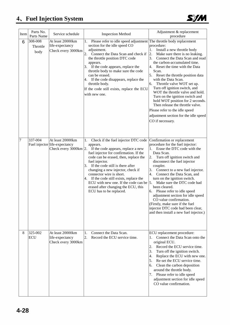
6 308-008
Throttle
body
At least 20000km life-expectancy
Check every 3000km
1. Please refer to idle speed adjustment section for the idle speed CO adjustment.
2. Connect the Data Scan and check if the throttle position DTC code appears.
3. If the code appears, replace the throttle body to make sure the code can be erased.
4. If the code disappears, replace the throttle body.
If the code still exists, replace the ECU
with new one.
The throttle body replacement procedure: 1. Install a new throttle body 2. Make sure there is no leaking. 3. Connect the Data Scan and read
the carbon-accumulated time. 4. Reset the time with the Data
Scan. 5. Reset the throttle position data
with the Data Scan. 6. Throttle valve WOT set up.
Turn off ignition switch, and WOT the throttle valve and hold. Turn on the ignition switch and hold WOT position for 2 seconds. Then release the throttle valve.
Please refer to the idle speed
adjustment section for the idle speed
CO if necessary.
7 337-004 Fuel injector
At least 20000km life-expectancy Check every 3000km
1. Check if the fuel injector DTC code appears.
2. If the code appears, replace a new fuel injector for confirmation. If the code can be erased, then, replace the fuel injector.
3. If the code still is there after changing a new injector, check if connector wire is short.
4. If the code still exists, replace the ECU with new one. If the code can be erased after changing the ECU, this ECU has to be replaced.
Confirmation or replacement procedure for the fuel injector: 1. Erase the DTC code with the
Data Scan. 2. Turn off ignition switch and
disconnect the fuel injector coupler.
3. Connect to a new fuel injector. 4. Connect the Data Scan, and
turn on the ignition switch. 5. Make sure the DTC code had
been cleared. 6. Please refer to idle speed
adjustment section for idle speed CO value confirmation.
(Firstly, make sure if the fuel injector DTC code had been clear, and then install a new fuel injector.)
8 325-002
ECU
At least 20000km
life-expectancy
Check every 3000km
1. Connect the Data Scan.
2. Record the ECU service time.
ECU replacement procedure:
1. Connect the Data Scan onto the
original ECU.
2. Record the ECU service time.
3. Turn off the ignition switch.
4. Replace the ECU with new one.
5. Re-set the ECU service time.
6. Clean the carbon deposition
around the throttle body.
7. Please refer to idle speed
adjustment section for idle speed
CO value confirmation.
4、Fuel Injection System
4-29
Item Parts No.
Parts Name Service schedule Inspection Method
Adjustment & replacement procedure
9 Idle speed
CO
Adjustment
Check for new
motorcycle and every
3000km.
1. Warm up the motorcycle by running
it in 50km/hr for 5 minutes.
2. Connect the Data Scan.
3. Record the idle speed CO value, and
engine rpm
4. In o2 sensor closed-loop system,
the CO value should be kept in
normal range. If the CO value
goes wild, please check the O2
sensor, engine, injector, and the
fuel system for malfunction.
1. Warm up the motorcycle by
running it in 50km/hr for 5
minutes.
2. Connect the Data Scan.
3. Record the idle speed CO
value, rpm.
4. Use the Data Scan to adjust the
idle speed CO value to be
0.5%~2.0%.
5. Record the idle speed CO
value, rpm and CO variant value.
6. (The engine temperature has to
be in 115℃~140℃, and intake
temperature to be in 25℃~40℃
as adjusting.)
7. Perform ECU learning
10 OZA591-BA1 O2 sensor
Check on new system and every 3000km
1. Use a Data Scan diagnostic to
check if there’s any DTC code.
2. Stop the engine for a while, and
let the engine temperature
return to the environmental
temperature.
3. Clear the DTC code and replace
a new sensor. If the DTC code
disappeared, the O2 sensor
should be replaced.
4. If the DTC code remains, check
the wire coupler for loose. And
also check the sensor for
abnormal resistance.
1. If O2 sensor should be
exchanged, the DTC code in
ECU must be erased first.
2. Turn off the ignition switch,
and remove the coupler.
3. Use the correct tool to remove
the sensor.
4. The tightening torque of the
O2 sensor is 3.6 to 4.6kgf-m。
5. Connect the coupler, and the
ECU. Turn on the ignition
switch.
6. Confirm the DTC code
disappeared.
7. Perform ECU learning
4、Fuel Injection System
4-30
ECU
Batte
ryR
egu
lator
17 4
15
08
12
13
09
0121
19
18
20
07
0316
22
AC
GC
PS
TP
SE
TT
-MA
P
Main
Sw
itch
Ch
eck
Lam
pD
iagn
ostic
5
Fu
el pu
mp
Injec
tor
By
-Pass
Valv
eC
oilIGND (B/W) 2
1
AIND
(R)
(W/B)
(G/L)FIND
DRVP(R) (R)
(R)
(R)
1
1
2
2
(B/Y)
(R)
(R)
(B)
(B)
(B/L)
ECUP
(B)
DRVG
CPS+
CPS-
XDRP
XDRG
TPIM
ETSM
MAPM
MATM
1
2
4
2
4
3
1
(L/R)
(B/R)
(P/G)
(Y/B)
(W/B)
(L/Y)
(Y/B)
(Y)
(G/W)
(Y)
(Y)
A
B
(B/R)
(G/W)
(R)
(G/W)
(G/W)
(R)
(B)
(Gr)
(B)
(G/W)
(G/B)
(R/W)
(G)
(G)
15A
LSD2
COMK
λ
10
14
main switch
(B)
(Gr)
(W)
(W)
ECU
Batte
ryR
egu
lator
17 4
15
08
12
13
09
0121
19
18
20
07
0316
22
AC
GC
PS
TP
SE
TT
-MA
P
Main
Sw
itch
Ch
eck
Lam
pD
iagn
ostic
5
Fu
el pu
mp
Injec
tor
By
-Pass
Valv
eC
oilIGND (B/W) 2
1
AIND
(R)
(W/B)
(G/L)FIND
DRVP(R) (R)
(R)
(R)
1
1
2
2
(B/Y)
(R)
(R)
(B)
(B)
(B/L)
ECUP
LSD4
(B)
DRVG
CPS+
CPS-
XDRP
XDRG
TPIM
ETSM
MAPM
MATM
1
2
4
2
4
3
1
(L/R)
(B/R)
(P/G)
(Y/B)
(W/B)
(L/Y)
(Y/B)
(Y)
(G/W)
(Y)
(Y)
A
B
(B/R)
(G/W)
(R)
(G/W)
(G/W)
(R)
(B)
(Gr)
(B)
(G/W)
(G/B)
(R/W)
(G)
(G)
15A
LSD2
COMK
O2
10
14
main switch
(B)
(Gr)
(W)
(W)
FDPP
ECU Connector Pin
4、Fuel Injection System
4-31
11 22
10 21
09 20
08 19
07 18
06 17
05 16
04 15
03 14
02 13
01 12
ASTM
COMK
CPS-
CPS+
XDRP
ECUP
XDRG
DRVP
AIND
IGND
ETSM
MAPM TPIM
LSD2
FIND
DRVG
11 22
10 21
09 20
08 19
07 18
06 17
05 16
04 15
03 14
02 13
01 12
ASTM
COMK
CPS-
CPS+
XDRP
ECUP
XDRG
DRVP
FDPP
AIND
IGND
ETSM
MAPM TPIM
LSD2
FIND
DRVG
O2
LSD4
ECU
ECU learning
Perform timing:
a. After exchanging ECU, Air by-pass valve, O2 sensor, throttle body.
b. After cleaning the throttle body or the air by-pass valve.
c. After disassembling and rebuilding the engine. Or after adjusting the tappet clearance.
d. After adjusting the idle CO value.
Method:
a. Warm the engine by driving the scooter by 50km/h for 5 minutes. ,The engine temperature should be around 90℃--120℃ (The standard engine temperature depends on different models or conditions.)
b. Maintain idle for 3—5 Minutes
Reset/Zeroing of the Throttle Position Sensor
Perform timing:
a. After exchanging the ECU or the Throttle body.
b. After adjusting the air screw (Only if necessary)
Method:
a. Connect the ECU
b. Turn on the ignition switch, and enter the reset/zeroing menu. Then press enter.
c. Turn off the ignition switch, hold the throttle on WOT position.
d. Turn on the ignition switch under WOT position.
e. Hold WOT position for 2 or 3 seconds, and release the throttle.
f. Turn on and off the switch for one time.
g. Make sure the throttle openness are on zero and 100% WOT position.
4、Fuel Injection System
4-32
NOTES: