Embed Size (px)
Citation preview
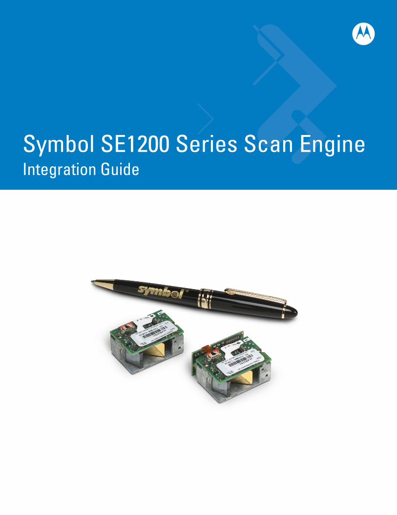
Symbol SE1200 Series Scan EngineIntegration Guide


Symbol SE1200 Series Scan EngineIntegration Guide
72E-58178-04
Revision A
February 2008
ii Symbol SE1200 Series Scan Engine Integration Guide
© 2007-2008 by Motorola, Inc. All rights reserved.
No part of this publication may be reproduced or used in any form, or by any electrical or mechanical means, without permission in writing from Motorola. This includes electronic or mechanical means, such as photocopying, recording, or information storage and retrieval systems. The material in this manual is subject to change without notice.
The software is provided strictly on an “as is” basis. All software, including firmware, furnished to the user is on a licensed basis. Motorola grants to the user a non-transferable and non-exclusive license to use each software or firmware program delivered hereunder (licensed program). Except as noted below, such license may not be assigned, sublicensed, or otherwise transferred by the user without prior written consent of Motorola. No right to copy a licensed program in whole or in part is granted, except as permitted under copyright law. The user shall not modify, merge, or incorporate any form or portion of a licensed program with other program material, create a derivative work from a licensed program, or use a licensed program in a network without written permission from Motorola. The user agrees to maintain Motorola’s copyright notice on the licensed programs delivered hereunder, and to include the same on any authorized copies it makes, in whole or in part. The user agrees not to decompile, disassemble, decode, or reverse engineer any licensed program delivered to the user or any portion thereof.
Motorola reserves the right to make changes to any software or product to improve reliability, function, or design.
Motorola does not assume any product liability arising out of, or in connection with, the application or use of any product, circuit, or application described herein.
No license is granted, either expressly or by implication, estoppel, or otherwise under any Motorola, Inc., intellectual property rights. An implied license only exists for equipment, circuits, and subsystems contained in Motorola products.
MOTOROLA and the Stylized M Logo and Symbol and the Symbol logo are registered in the US Patent & Trademark Office. Bluetooth is a registered trademark of Bluetooth SIG. Microsoft, Windows and ActiveSync are either registered trademarks or trademarks of Microsoft Corporation. All other product or service names are the property of their respective owners.
Motorola, Inc.One Motorola PlazaHoltsville, New York 11742-1300http://www.symbol.com
PatentsThis product is covered by one or more of the patents listed on the website: http://www.symbol.com/patents
WarrantyFor the complete Motorola hardware product warranty statement, go to: http://www.symbol.com/warranty.
iii
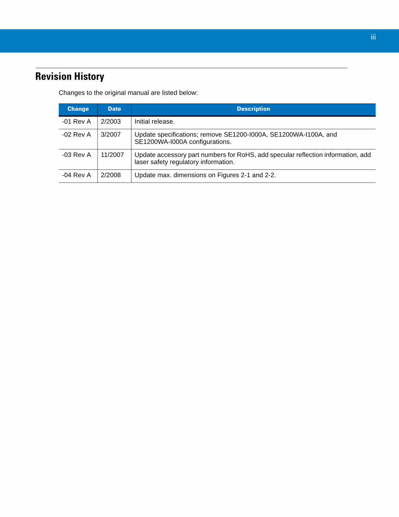
Revision HistoryChanges to the original manual are listed below:
Change Date Description
-01 Rev A 2/2003 Initial release.
-02 Rev A 3/2007 Update specifications; remove SE1200-I000A, SE1200WA-I100A, and SE1200WA-I000A configurations.
-03 Rev A 11/2007 Update accessory part numbers for RoHS, add specular reflection information, add laser safety regulatory information.
-04 Rev A 2/2008 Update max. dimensions on Figures 2-1 and 2-2.

iv Symbol SE1200 Series Scan Engine Integration Guide
Table of Contents
About This GuideIntroduction .................................................................................................................... ixChapter Descriptions ..................................................................................................... ixNotational Conventions.................................................................................................. xService Information........................................................................................................ x
Chapter 1: IntroductionOverview ....................................................................................................................... 1-1Theory of Operation ...................................................................................................... 1-2
Block Diagram ......................................................................................................... 1-2Electrical Interface ........................................................................................................ 1-4
Chapter 2: InstallationIntroduction ................................................................................................................... 2-1Unpacking ..................................................................................................................... 2-1Mounting ....................................................................................................................... 2-1Installing the Scan Engine ............................................................................................ 2-2Housing Design ............................................................................................................ 2-3
Environment ............................................................................................................ 2-3Grounding ..................................................................................................................... 2-3ESD .............................................................................................................................. 2-3Optical ........................................................................................................................... 2-3
Positioning the Exit Window .................................................................................... 2-4Avoiding Scratched Windows ................................................................................. 2-6Window Material ..................................................................................................... 2-7Commercially Available Coatings ........................................................................... 2-8
Location and Positioning ............................................................................................... 2-9Specular Reflection ................................................................................................. 2-9Using the Symbol SE1200 as an Embedded Scanner ........................................... 2-10Conveyor Applications ............................................................................................ 2-12
Accessories .................................................................................................................. 2-14Hardware Accessories ............................................................................................ 2-14
vi Symbol SE1200 Series Scan Engine Integration Guide
Flex Cable ............................................................................................................... 2-15Software Development Kit ...................................................................................... 2-16
Chapter 3: Symbol SE1200HP-I10xA SpecificationsIntroduction ................................................................................................................... 3-1Technical Specifications ............................................................................................... 3-1
Electrical Interface .................................................................................................. 3-1Decode Zone ................................................................................................................ 3-4
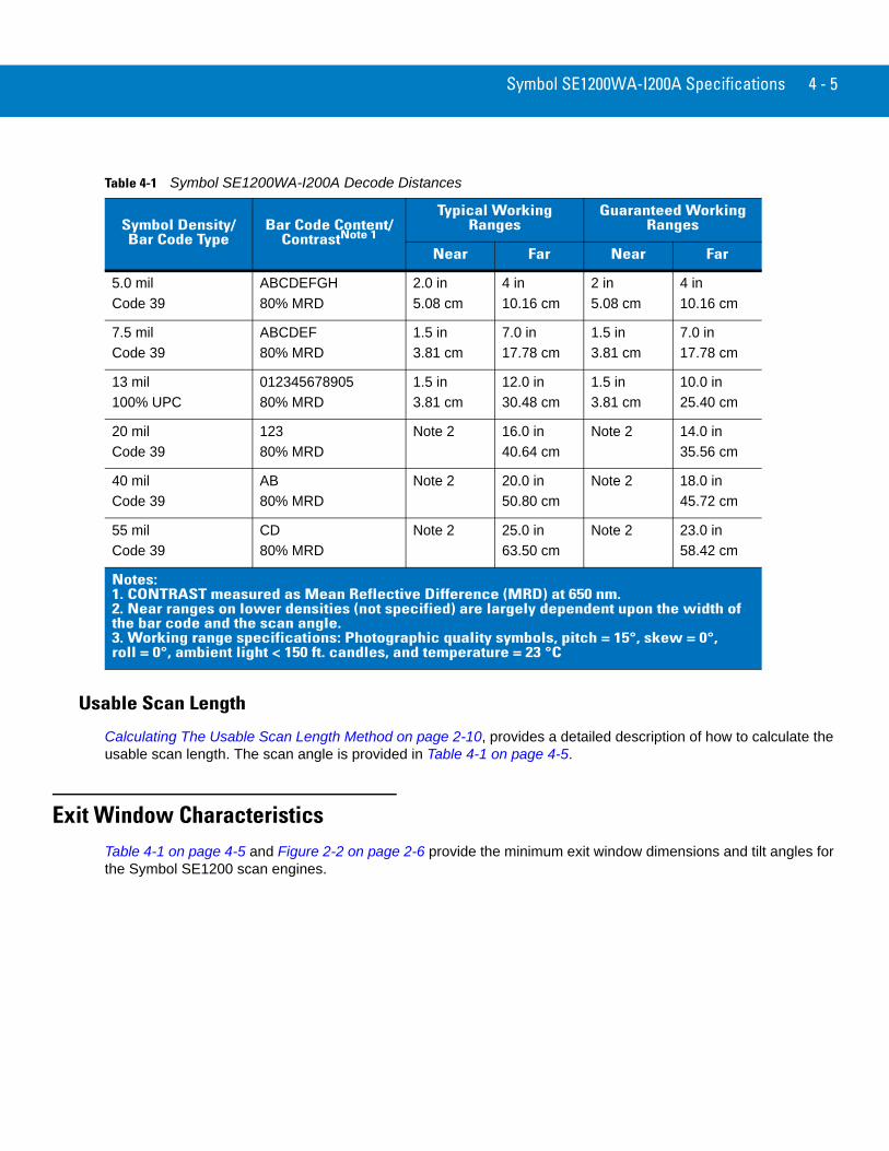
Usable Scan Length ................................................................................................ 3-5Exit Window Characteristics ......................................................................................... 3-5
Chapter 4: Symbol SE1200WA-I200A SpecificationsIntroduction ................................................................................................................... 4-1Technical Specifications ............................................................................................... 4-1
Electrical Interface .................................................................................................. 4-1Decode Zone ................................................................................................................ 4-4
Usable Scan Length ................................................................................................ 4-5Exit Window Characteristics ......................................................................................... 4-5
Chapter 5: Symbol SE1200VHD-I000A SpecificationIntroduction ................................................................................................................... 5-1Symbol SE1200VHD-I000A Technical Specifications .................................................. 5-1
Electrical Interface .................................................................................................. 5-1Symbol SE1200VHD-I000A Decode Zone (Vcc = 5V) ................................................. 5-4
Usable Scan Length ................................................................................................ 5-5Exit Window Characteristics ......................................................................................... 5-5
Chapter 6: Symbol SE1200LR-I001A SpecificationIntroduction ................................................................................................................... 6-1Symbol SE1200LR-I001A Technical Specifications ..................................................... 6-1
Electrical Interface .................................................................................................. 6-1Symbol SE1200LR-I001A Decode Zone (Vcc = 5V) .................................................... 6-4
Usable Scan Length ................................................................................................ 6-5Exit Window Characteristics ......................................................................................... 6-5
Chapter 7: Symbol SE1200ALR-I000A SpecificationIntroduction ................................................................................................................... 7-1Symbol SE1200ALR-I000A Technical Specifications ................................................... 7-1
Electrical Interface .................................................................................................. 7-1Symbol SE1200ALR-I000A Decode Zone (Vcc = 5V) .................................................. 7-4
Usable Scan Length ................................................................................................ 7-5Exit Window Characteristics ......................................................................................... 7-5
Table of Contents vii
Chapter 8: Regulatory RequirementsIntroduction ................................................................................................................... 8-1General Regulatory Requirements ............................................................................... 8-1Required Documentation for Class 1 Laser Products ................................................... 8-1Required Documentation for Class 2 Laser Products ................................................... 8-2
Chapter 9: TroubleshootingIntroduction ................................................................................................................... 9-1Troubleshooting ............................................................................................................ 9-1
Glossary
Index
Tell Us What You Think...

viii Symbol SE1200 Series Scan Engine Integration Guide

About This Guide
IntroductionThe Symbol SE1200 Series Scan Engine Integration Guide provides general instructions for mounting and set up of the Symbol SE1200 series scan engines.
Chapter DescriptionsTopics covered in this guide are as follows:
• Chapter 1, Introduction, provides an Overview of the scan engines as well as the Theory of Operation and the Electrical Interface information.
• Chapter 2, Installation, explains how to install the scan engines. Provides detailed information on Mounting, Installation, Housing Design, Grounding, ESD, Environmental, Optical, Location and Positioning requirements are provided. Information on accessories is also provided.
• Chapter 3, Symbol SE1200HP-I10xA Specifications, provides the Symbol SE1200HP-I10xA scan engine technical specifications.
• Chapter 4, Symbol SE1200WA-I200A Specifications, provides the Symbol SE1200WA-I200A scan engine technical specifications.
• Chapter 5, Symbol SE1200VHD-I000A Specification, provides the Symbol SE1200VHD-I000A scan engine technical specifications.
• Chapter 6, Symbol SE1200LR-I001A Specification, provides the Symbol SE1200LR-I001A scan engine technical specifications.
• Chapter 7, Symbol SE1200ALR-I000A Specification, provides the Symbol SE1200ALR-I000A scan engine technical specifications.
• Chapter 8, Regulatory Requirements, describes the integration, documentation, and labeling requirements for Class 1 and Class 2 laser products.
NOTE This guide provides general instructions for the installation of the scan engine into a customer's device. It is recommended that an opto-mechanical engineer perform a opto-mechanical analysis prior to integration.
x Symbol SE1200 Series Scan Engine Integration Guide
• Chapter 9, Troubleshooting, provides the scan engines Troubleshooting procedures.
Notational ConventionsThe following conventions are used in this document:
• Italics are used to highlight specific items in the general text, and to identify chapters and sections in this and related documents.
• Bullets (•) indicate:• action items• lists of alternatives• lists of required steps that are not necessarily sequential.
• Sequential lists (e.g., those that describe step-by-step procedures) appear as numbered lists.
Service InformationIf you have a problem with your equipment, contact Motorola Enterprise Mobility Support for your region. Contact information is available at: http://www.symbol.com/contactsupport.
When contacting Enterprise Mobility Support, please have the following information available:
• Serial number of the unit
• Model number or product name
• Software type and version number.
Motorola responds to calls by E-mail, telephone or fax within the time limits set forth in support agreements.
If your problem cannot be solved by Motorola Enterprise Mobility Support, you may need to return your equipment for servicing and will be given specific directions. Motorola is not responsible for any damages incurred during shipment if the approved shipping container is not used. Shipping the units improperly can possibly void the warranty.
If you purchased your Enterprise Mobility business product from a Motorola business partner, contact that business partner for support.
NOTE This symbol indicates something of special interest or importance to the reader. Failure to read the note will not result in physical harm to the reader, equipment or data.
CAUTION This symbol indicates that if this information is ignored, the possiblity of data or material damage may occur.
WARNING! This symbol indicates that if this information is ignored the possibility that serious personal injury may occur.
Chapter 1 Introduction
OverviewThe Symbol SE1200 is a miniaturized, high performance, visible-laser based scan engine intended for integration into OEM equipment.
Motorola’s state-of-the-art laser technology provides the highest first read rates, accuracy, a wide decode zone, and excellent reliability.
Available versions include:
• Symbol SE1200HP-I10xA Specifications on page 3-1
• Symbol SE1200WA-I200A Specifications on page 4-1
• Symbol SE1200VHD-I000A Specification on page 5-1
• Symbol SE1200LR-I001A Specification on page 6-1
• Symbol SE1200ALR-I000A Specification on page 7-1
A zif connector mounted on the scan engine provides connection between the scanner and host, or hardware acquisition/decoder element.
WARNING! Per FDA and IEC standards, the scan engines described in this guide are not given a laser classification. However, the following precautions should be observed. This laser component emits FDA/IEC Class 2 laser light at the exit port. Do not stare into beam.
1 - 2 Symbol SE1200 Series Scan Engine Integration Guide
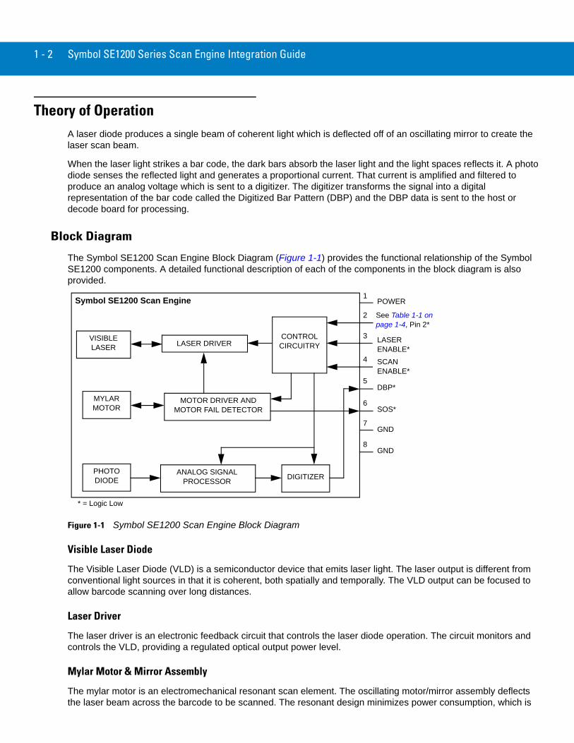
Theory of OperationA laser diode produces a single beam of coherent light which is deflected off of an oscillating mirror to create the laser scan beam.
When the laser light strikes a bar code, the dark bars absorb the laser light and the light spaces reflects it. A photo diode senses the reflected light and generates a proportional current. That current is amplified and filtered to produce an analog voltage which is sent to a digitizer. The digitizer transforms the signal into a digital representation of the bar code called the Digitized Bar Pattern (DBP) and the DBP data is sent to the host or decode board for processing.
Block Diagram
The Symbol SE1200 Scan Engine Block Diagram (Figure 1-1) provides the functional relationship of the Symbol SE1200 components. A detailed functional description of each of the components in the block diagram is also provided.
Figure 1-1 Symbol SE1200 Scan Engine Block Diagram
Visible Laser Diode
The Visible Laser Diode (VLD) is a semiconductor device that emits laser light. The laser output is different from conventional light sources in that it is coherent, both spatially and temporally. The VLD output can be focused to allow barcode scanning over long distances.
Laser Driver
The laser driver is an electronic feedback circuit that controls the laser diode operation. The circuit monitors and controls the VLD, providing a regulated optical output power level.
Mylar Motor & Mirror Assembly
The mylar motor is an electromechanical resonant scan element. The oscillating motor/mirror assembly deflects the laser beam across the barcode to be scanned. The resonant design minimizes power consumption, which is
Symbol SE1200 Scan Engine
VISIBLE LASER
MYLAR MOTOR
PHOTO DIODE
MOTOR DRIVER AND MOTOR FAIL DETECTOR
ANALOG SIGNAL PROCESSOR DIGITIZER
CONTROL CIRCUITRYLASER DRIVER
1
2
3
4
5
6
7
8
POWER
See Table 1-1 on page 1-4, Pin 2*
LASER ENABLE*
SCAN ENABLE*
DBP*
SOS*
GND
GND
* = Logic Low
Introduction 1 - 3
especially important in battery operated applications. The scan element has been designed to be highly rugged and reliable.
Motor Driver
The motor driver is an electromagnetic and electronic circuit that provides feedback control of the mylar motor scan element. The circuit regulates the scan amplitude of the motor/mirror assembly. The scan frequency is determined by the resonance characteristics of the mechanical design. The motor fail detector is a laser safety circuit that monitors the motor behavior, and turns off the VLD if the motor fails to operate. The SOS (Start Of Scan) signal transitions from high to low and low to high, corresponding to the edges of the scan line. The signal frames the data received by a complete scan line.
Control Circuitry
Interface circuitry controls operation of the scanner, motor, and laser, depending on the states of the input signals from the host device.
Photodiode
The photodiode is a transducer that converts incident light energy into an electrical current. It is the “eye” of the scan engine. When the laser beam passes over a barcode, the black bars absorb the light and the white spaces reflect the light. Collection optics focus the received reflected light onto the photodiode. The photodiode produces a photocurrent proportional to the received optical signal.
Analog Signal Processor
The Analog Signal Processor is a transimpedance preamplifier which converts the photocurrent into a voltage and provides amplification. Additional amplifier stages provide signal gain and bandpass filtering. The AGC (Automatic Gain Control) circuit is a feedback loop that monitors the received signal voltage level and varies the voltage gain to maintain a constant amplitude at the output. The output analog signal is then input into the digitizer.
Digitizer
The digitizer is an edge detection circuit that takes the amplified and filtered analog signal and converts it into a digital representation of the scanned barcode. The output of the digitizer is called the DBP (Digitized Bar Pattern). The widths of the DBP elements are proportional to the printed bars and spaces of the barcode. The DBP signal is sent to the decoder board or host computer to decode the data.
1 - 4 Symbol SE1200 Series Scan Engine Integration Guide
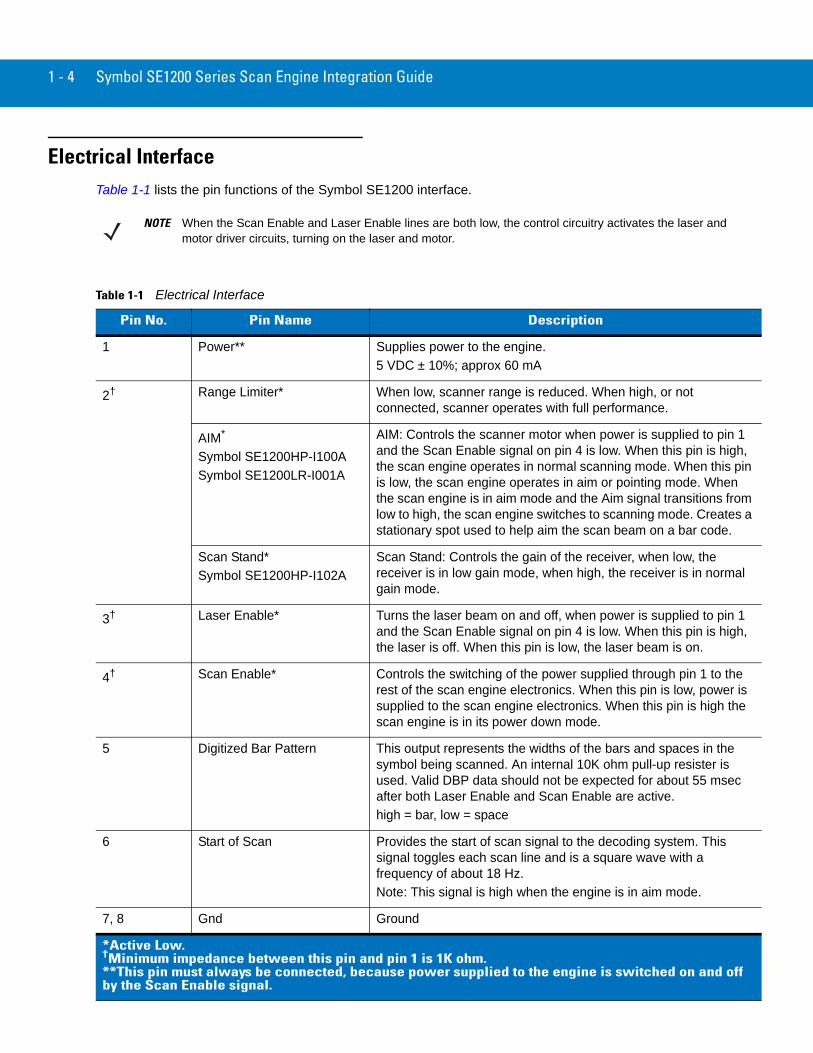
Electrical InterfaceTable 1-1 lists the pin functions of the Symbol SE1200 interface.
NOTE When the Scan Enable and Laser Enable lines are both low, the control circuitry activates the laser and motor driver circuits, turning on the laser and motor.
Table 1-1 Electrical Interface
Pin No. Pin Name Description
1 Power** Supplies power to the engine.5 VDC ± 10%; approx 60 mA
2† Range Limiter* When low, scanner range is reduced. When high, or not connected, scanner operates with full performance.
AIM*
Symbol SE1200HP-I100ASymbol SE1200LR-I001A
AIM: Controls the scanner motor when power is supplied to pin 1 and the Scan Enable signal on pin 4 is low. When this pin is high, the scan engine operates in normal scanning mode. When this pin is low, the scan engine operates in aim or pointing mode. When the scan engine is in aim mode and the Aim signal transitions from low to high, the scan engine switches to scanning mode. Creates a stationary spot used to help aim the scan beam on a bar code.
Scan Stand*Symbol SE1200HP-I102A
Scan Stand: Controls the gain of the receiver, when low, the receiver is in low gain mode, when high, the receiver is in normal gain mode.
3† Laser Enable* Turns the laser beam on and off, when power is supplied to pin 1 and the Scan Enable signal on pin 4 is low. When this pin is high, the laser is off. When this pin is low, the laser beam is on.
4† Scan Enable* Controls the switching of the power supplied through pin 1 to the rest of the scan engine electronics. When this pin is low, power is supplied to the scan engine electronics. When this pin is high the scan engine is in its power down mode.
5 Digitized Bar Pattern This output represents the widths of the bars and spaces in the symbol being scanned. An internal 10K ohm pull-up resister is used. Valid DBP data should not be expected for about 55 msec after both Laser Enable and Scan Enable are active.high = bar, low = space
6 Start of Scan Provides the start of scan signal to the decoding system. This signal toggles each scan line and is a square wave with a frequency of about 18 Hz. Note: This signal is high when the engine is in aim mode.
7, 8 Gnd Ground
*Active Low.†Minimum impedance between this pin and pin 1 is 1K ohm.**This pin must always be connected, because power supplied to the engine is switched on and off by the Scan Enable signal.

Chapter 2 Installation
IntroductionThis chapter provides the Symbol SE1200 scan engine unpacking, mounting and installing requirements information. Physical and electrical considerations are provided, together with the recommended window properties.
Unpacking Remove the Symbol SE1200 from its packing and inspect the scanner for evidence of physical damage. If the scanner was damaged in transit, see Service Information on page x for more information.
KEEP THE PACKING. It is the approved shipping container and should be used if the equipment needs to be returned for servicing.
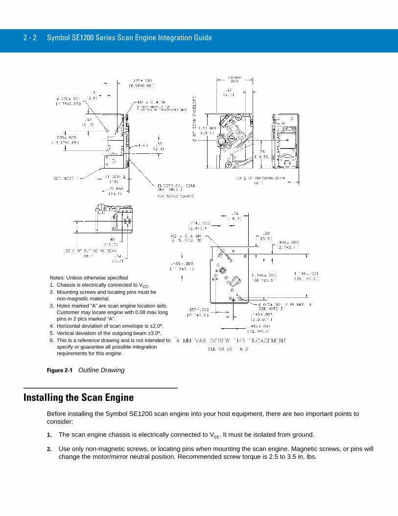
MountingMounting holes (M2x0.4-6H), are provided on the bottom of the chassis. Figure 2-1 on page 2-2 provides an outline drawing of the Symbol SE1200 scan engines.
The Symbol SE1200 scan engines may be mounted in any orientation without any degradation in performance.
2 - 2 Symbol SE1200 Series Scan Engine Integration Guide
Figure 2-1 Outline Drawing
Installing the Scan EngineBefore installing the Symbol SE1200 scan engine into your host equipment, there are two important points to consider:
1. The scan engine chassis is electrically connected to Vcc. It must be isolated from ground.
2. Use only non-magnetic screws, or locating pins when mounting the scan engine. Magnetic screws, or pins will change the motor/mirror neutral position. Recommended screw torque is 2.5 to 3.5 in. lbs.
Notes: Unless otherwise specified1. Chassis is electrically connected to VCC.2. Mounting screws and locating pins must be
non-magnetic material.3. Holes marked “A” are scan engine location aids.
Customer may locate engine with 0.08 max long pins in 2 plcs marked “A”.
4. Horizontal deviation of scan envelope is ±2.0º.5. Vertical deviation of the outgoing beam ±3.0º.6. This is a reference drawing and is not intended to
specify or guarantee all possible integration requirements for this engine.
1.01 MAX[25.7]

Installation 2 - 3
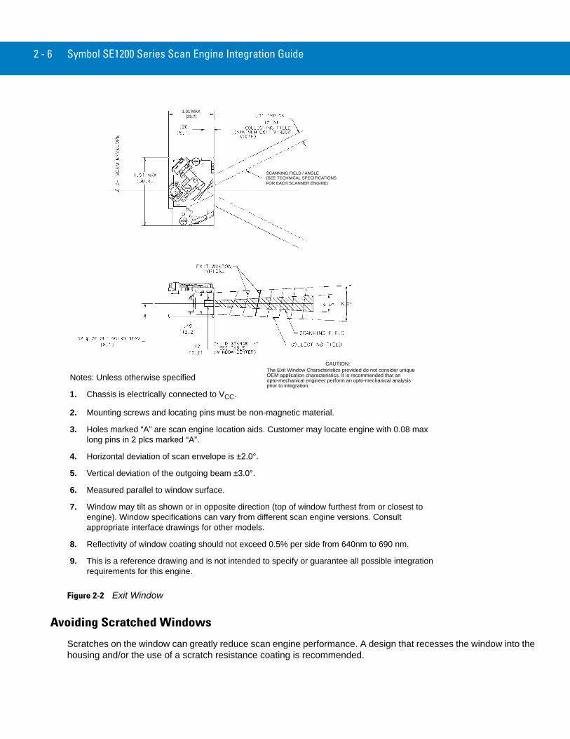
Housing DesignThe scan engine housing design must be such that internal reflections from the outgoing laser beam are not directed back toward the detector. The reflections from the front corners of the scan engine housing near the exit window and from the window itself can often be troublesome. Also, for particular window tilt angles, reflections from the window can bounce off the top or bottom of the housing and reach the detector.
The Exit Window Information tables (see Exit Window Characteristics on page 2-4) provide minimum exit window dimensions and tilt angles for particular scan engine variants. One should note that these dimensional requirements can vary for different engine types. In addition to these minimum dimensional requirements, the designer may want to consider the use of baffles, matte-finished dark internal housing colors, as well as anti-reflection coated windows.
Environment
The scan engine must be sufficiently enclosed to prevent dust particles from gathering on the mirrors, laser lens, and the photodiode. Dust and other external contaminants will eventually cause degradation in unit performance. Motorola does not warrant performance of the engine when used in an exposed application. An exit window is required in all housing designs. Refer to Optical on page 2-3 for positioning of the exit window.
GroundingThe scan engine chassis is at VCC. If the scan engine is being mounted on a grounded host, they must be electrically isolated.
An insulator can be inserted between the two chassis, and if metallic (non-magnetic) screws are used, shoulder washers must be used to isolate the screws from the host. Non-metallic screws may also be used if mechanical considerations permit.
When installing metallic, non-magnetic screws, make sure that the screwdriver or screw tip is non-magnetic. Magnetic screwdrivers or screw tips will change the motor/mirror neutral position.
ESDThe scan engines are protected from ESD events that may occur in an ESD-controlled environment. Always exercise care when handling the module. Use grounding wrist straps and handle in a properly grounded work area.
OpticalThe scan engine uses a sophisticated optical system that is capable of providing scanning performance that can match or exceed the performance of much larger scanners. However, the performance of the scan engine can be affected by an improperly designed enclosure, or improper selection of the window material.
CAUTION This guide provides general instructions for the installation of the scan engine in a customer's device. It is recommended that an opto-mechanical engineer perform an opto-mechanical analysis prior to integration.
2 - 4 Symbol SE1200 Series Scan Engine Integration Guide
Positioning the Exit Window
The exit window must be positioned so that laser light reflected off the inside of the exit window is not reflected back into the collection optics of the scan engine. If an anti-reflection coating is used, the window can be positioned more nearly parallel to the face of the scanner. It is important to allow for manufacturing tolerances when determining the angles, it is essential to maintain the minimum angles specified in Exit Window Characteristics on page 2-4.
Larger angles are generally preferred. To maximize your system’s potential, including use with the entire scan engine family (including 2-D scanners), a minimum angle of 24° is recommended. If your enclosure design cannot accommodate the recommended window angle, contact Motorola to discuss your requirements. An improperly positioned window can result in significant performance degradation.
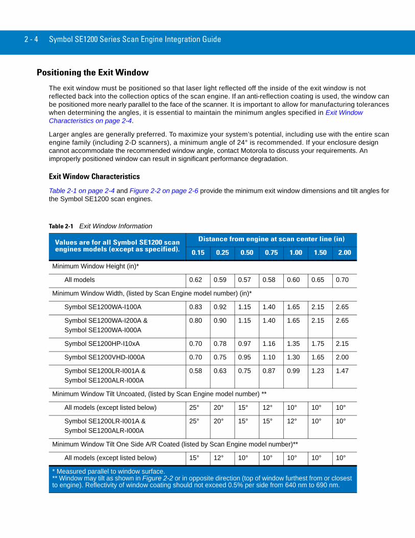
Exit Window Characteristics
Table 2-1 on page 2-4 and Figure 2-2 on page 2-6 provide the minimum exit window dimensions and tilt angles for the Symbol SE1200 scan engines.
Table 2-1 Exit Window Information
Values are for all Symbol SE1200 scan engines models (except as specified).
Distance from engine at scan center line (in)
0.15 0.25 0.50 0.75 1.00 1.50 2.00
Minimum Window Height (in)*
All models 0.62 0.59 0.57 0.58 0.60 0.65 0.70
Minimum Window Width, (listed by Scan Engine model number) (in)*
Symbol SE1200WA-I100A 0.83 0.92 1.15 1.40 1.65 2.15 2.65
Symbol SE1200WA-I200A & Symbol SE1200WA-I000A
0.80 0.90 1.15 1.40 1.65 2.15 2.65
Symbol SE1200HP-I10xA 0.70 0.78 0.97 1.16 1.35 1.75 2.15
Symbol SE1200VHD-I000A 0.70 0.75 0.95 1.10 1.30 1.65 2.00
Symbol SE1200LR-I001A &Symbol SE1200ALR-I000A
0.58 0.63 0.75 0.87 0.99 1.23 1.47
Minimum Window Tilt Uncoated, (listed by Scan Engine model number) **
All models (except listed below) 25° 20° 15° 12° 10° 10° 10°
Symbol SE1200LR-I001A &Symbol SE1200ALR-I000A
25° 20° 15° 15° 12° 10° 10°
Minimum Window Tilt One Side A/R Coated (listed by Scan Engine model number)**
All models (except listed below) 15° 12° 10° 10° 10° 10° 10°
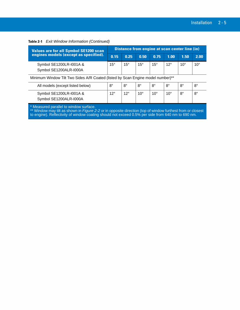
* Measured parallel to window surface.** Window may tilt as shown in Figure 2-2 or in opposite direction (top of window furthest from or closest to engine). Reflectivity of window coating should not exceed 0.5% per side from 640 nm to 690 nm.
Installation 2 - 5
Symbol SE1200LR-I001A &Symbol SE1200ALR-I000A
15° 15° 15° 15° 12° 10° 10°
Minimum Window Tilt Two Sides A/R Coated (listed by Scan Engine model number)**
All models (except listed below) 8° 8° 8° 8° 8° 8° 8°
Symbol SE1200LR-I001A &Symbol SE1200ALR-I000A
12° 12° 10° 10° 10° 8° 8°
Table 2-1 Exit Window Information (Continued)
Values are for all Symbol SE1200 scan engines models (except as specified).
Distance from engine at scan center line (in)
0.15 0.25 0.50 0.75 1.00 1.50 2.00
* Measured parallel to window surface.** Window may tilt as shown in Figure 2-2 or in opposite direction (top of window furthest from or closest to engine). Reflectivity of window coating should not exceed 0.5% per side from 640 nm to 690 nm.
2 - 6 Symbol SE1200 Series Scan Engine Integration Guide
Figure 2-2 Exit Window
Avoiding Scratched Windows
Scratches on the window can greatly reduce scan engine performance. A design that recesses the window into the housing and/or the use of a scratch resistance coating is recommended.
Notes: Unless otherwise specified
1. Chassis is electrically connected to VCC.
2. Mounting screws and locating pins must be non-magnetic material.
3. Holes marked “A” are scan engine location aids. Customer may locate engine with 0.08 max long pins in 2 plcs marked “A”.
4. Horizontal deviation of scan envelope is ±2.0°.
5. Vertical deviation of the outgoing beam ±3.0°.
6. Measured parallel to window surface.
7. Window may tilt as shown or in opposite direction (top of window furthest from or closest to engine). Window specifications can vary from different scan engine versions. Consult appropriate interface drawings for other models.
8. Reflectivity of window coating should not exceed 0.5% per side from 640nm to 690 nm.
9. This is a reference drawing and is not intended to specify or guarantee all possible integration requirements for this engine.
(SEE TECHNICAL SPECIFICATIONSFOR EACH SCANNER ENGINE)
SCANNING FIELD / ANGLE
The Exit Window Characteristics provided do not consider unique OEM application characteristics. It is recommended that an opto-mechanical engineer perform an opto-mechanical analysis prior to integration.
CAUTION:
1.01 MAX[25.7]
Installation 2 - 7
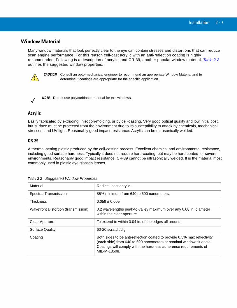
Window Material
Many window materials that look perfectly clear to the eye can contain stresses and distortions that can reduce scan engine performance. For this reason cell-cast acrylic with an anti-reflection coating is highly recommended. Following is a description of acrylic, and CR-39, another popular window material. Table 2-2 outlines the suggested window properties.
Acrylic
Easily fabricated by extruding, injection-molding, or by cell-casting. Very good optical quality and low initial cost, but surface must be protected from the environment due to its susceptibility to attack by chemicals, mechanical stresses, and UV light. Reasonably good impact resistance. Acrylic can be ultrasonically welded.
CR-39
A thermal-setting plastic produced by the cell-casting process. Excellent chemical and environmental resistance, including good surface hardness. Typically it does not require hard-coating, but may be hard coated for severe environments. Reasonably good impact resistance. CR-39 cannot be ultrasonically welded. It is the material most commonly used in plastic eye glasses lenses.
CAUTION Consult an opto-mechanical engineer to recommend an appropriate Window Material and to determine if coatings are appropriate for the specific application.
NOTE Do not use polycarbinate material for exit windows.
Table 2-2 Suggested Window Properties
Material Red cell-cast acrylic.
Spectral Transmission 85% minimum from 640 to 690 nanometers.
Thickness 0.059 ± 0.005
Wavefront Distortion (transmission) 0.2 wavelengths peak-to-valley maximum over any 0.08 in. diameter within the clear aperture.
Clear Aperture To extend to within 0.04 in. of the edges all around.
Surface Quality 60-20 scratch/dig
Coating Both sides to be anti-reflection coated to provide 0.5% max reflectivity (each side) from 640 to 690 nanometers at nominal window tilt angle. Coatings will comply with the hardness adherence requirements of MIL-M-13508.
2 - 8 Symbol SE1200 Series Scan Engine Integration Guide
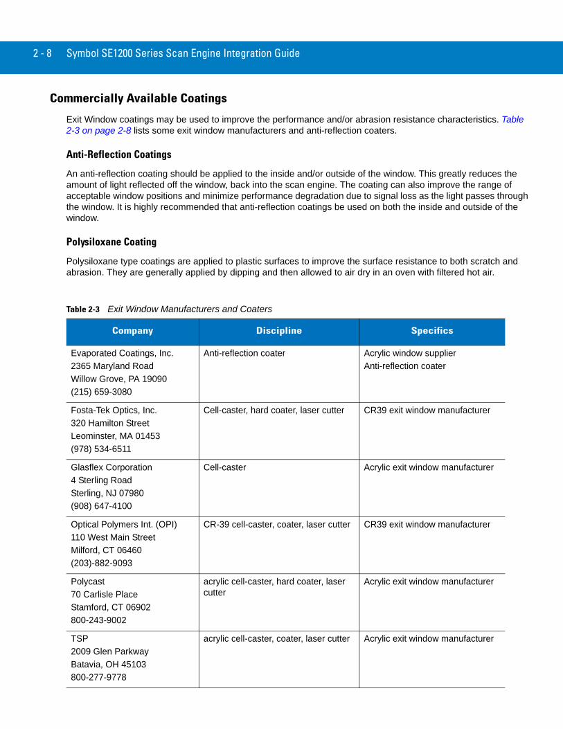
Commercially Available Coatings
Exit Window coatings may be used to improve the performance and/or abrasion resistance characteristics. Table 2-3 on page 2-8 lists some exit window manufacturers and anti-reflection coaters.
Anti-Reflection Coatings
An anti-reflection coating should be applied to the inside and/or outside of the window. This greatly reduces the amount of light reflected off the window, back into the scan engine. The coating can also improve the range of acceptable window positions and minimize performance degradation due to signal loss as the light passes through the window. It is highly recommended that anti-reflection coatings be used on both the inside and outside of the window.
Polysiloxane Coating
Polysiloxane type coatings are applied to plastic surfaces to improve the surface resistance to both scratch and abrasion. They are generally applied by dipping and then allowed to air dry in an oven with filtered hot air.
Table 2-3 Exit Window Manufacturers and Coaters
Company Discipline Specifics
Evaporated Coatings, Inc.2365 Maryland RoadWillow Grove, PA 19090(215) 659-3080
Anti-reflection coater Acrylic window supplier Anti-reflection coater
Fosta-Tek Optics, Inc.320 Hamilton StreetLeominster, MA 01453(978) 534-6511
Cell-caster, hard coater, laser cutter CR39 exit window manufacturer
Glasflex Corporation4 Sterling RoadSterling, NJ 07980(908) 647-4100
Cell-caster Acrylic exit window manufacturer
Optical Polymers Int. (OPI)110 West Main StreetMilford, CT 06460(203)-882-9093
CR-39 cell-caster, coater, laser cutter CR39 exit window manufacturer
Polycast70 Carlisle PlaceStamford, CT 06902800-243-9002
acrylic cell-caster, hard coater, laser cutter
Acrylic exit window manufacturer
TSP2009 Glen ParkwayBatavia, OH 45103800-277-9778
acrylic cell-caster, coater, laser cutter Acrylic exit window manufacturer
Installation 2 - 9
Location and Positioning
Specular Reflection
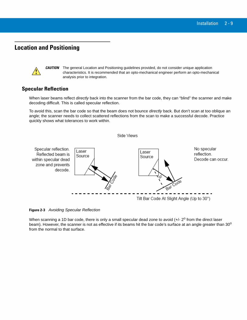
When laser beams reflect directly back into the scanner from the bar code, they can “blind” the scanner and make decoding difficult. This is called specular reflection.
To avoid this, scan the bar code so that the beam does not bounce directly back. But don’t scan at too oblique an angle; the scanner needs to collect scattered reflections from the scan to make a successful decode. Practice quickly shows what tolerances to work within.
Figure 2-3 Avoiding Specular Reflection
When scanning a 1D bar code, there is only a small specular dead zone to avoid (+/- 2o from the direct laser beam). However, the scanner is not as effective if its beams hit the bar code’s surface at an angle greater than 30o from the normal to that surface.
CAUTION The general Location and Positioning guidelines provided, do not consider unique application characteristics. It is recommended that an opto-mechanical engineer perform an opto-mechanical analysis prior to integration.
2 - 10 Symbol SE1200 Series Scan Engine Integration Guide
Using the Symbol SE1200 as an Embedded Scanner
Some applications require the Symbol SE1200 be mounted to read symbols that are automatically presented, or that are presented in a pre-determined location. In these applications the Symbol SE1200 positioning (with respect to the symbol) is critical. Failure to properly position the Symbol SE1200 with respect to the symbol may lead to degraded or unsatisfactory reading performance.
Two methods of positioning the scanner have been provided:
• The Calculating The Usable Scan Length Method on page 2-10, can be used with consistently good quality symbols. It provides a mathematical solution to find the usable scan length.
• The Testing The Usable Scan Length Method on page 2-11, uses real situation testing to adjust the usable scan length to fit the application conditions.
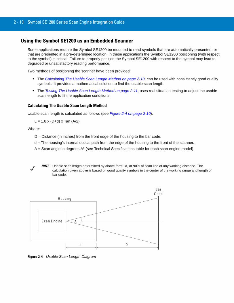
Calculating The Usable Scan Length Method
Usable scan length is calculated as follows (see Figure 2-4 on page 2-10):
L = 1.8 x (D+d) x Tan (A/2)
Where:
D = Distance (in inches) from the front edge of the housing to the bar code.d = The housing’s internal optical path from the edge of the housing to the front of the scanner.A = Scan angle in degrees A° (see Technical Specifications table for each scan engine model).
Figure 2-4 Usable Scan Length Diagram
NOTE Usable scan length determined by above formula, or 90% of scan line at any working distance. The calculation given above is based on good quality symbols in the center of the working range and length of bar code.
Scan Engine
Housing
d D
A
BarCode
Installation 2 - 11
Testing The Usable Scan Length Method
Due to the large variety of symbol sizes, densities, print quality, etc., there is no simple way to calculate the optimum symbol distance. To ensure optimum performance use the Testing The Usable Scan Length positioning method to maximize performance.
Determining the optimum distance between the scan engine and the symbol:
1. Measure the maximum and minimum distances at which the symbols can be read.
2. Check the near and far range on several symbols. If they are not reasonably consistent there may be a printing quality problem that can degrade the performance of your system. Motorola can provide advice on how to improve the installation.
3. Locate the scanner so the symbol is near the middle of the near/far range.
4. Center the symbol (left to right) in the scan line whenever possible.
5. Position the symbol so that the scan line is as near as possible to perpendicular to the bars and spaces in the symbol.
6. Avoid specular reflection (glare) by tilting the top or bottom of the symbol away from the engine. The exact angle is not critical, but it must be large enough so that if a mirror were inserted in the symbol location, the reflected scan line would miss the front surface of the engine. For the maximum allowable angles refer to the Skew, Pitch and Roll angles listed in each scan engine’s Technical Specifications Table.
7. If an additional window is to be placed between the scanner and the symbol, the determination of optimum symbol location should be made with a representative window in the desired window position. Review the sections of this chapter concerning window quality, coatings and positioning.
8. Give the scanner time to dwell on the symbol for several scans. When first enabled, the scan engine may take two or three scans before it reaches maximum performance. Enable the scan engine before the symbol is presented, if possible.
NOTE Poor quality symbols (from bad printing, wear, or damage) may not decode well when placed in the center of the depth of field (especially true of higher density codes). The scan beam has a minimum width in the central area, and when the scanner tries to read all the symbol imperfections in this area it may end up with no decode. Therefore, after a preliminary spot is determined using good quality symbols, several of lessor quality symbols should be tested and the spot adjusted for the best overall symbol position.
2 - 12 Symbol SE1200 Series Scan Engine Integration Guide
Conveyor Applications
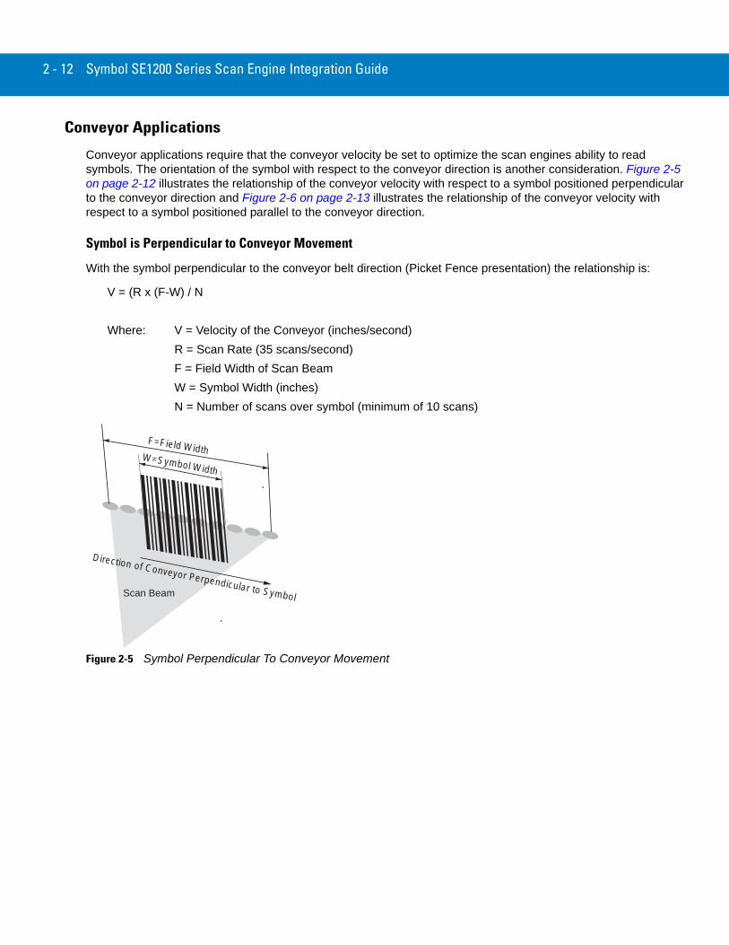
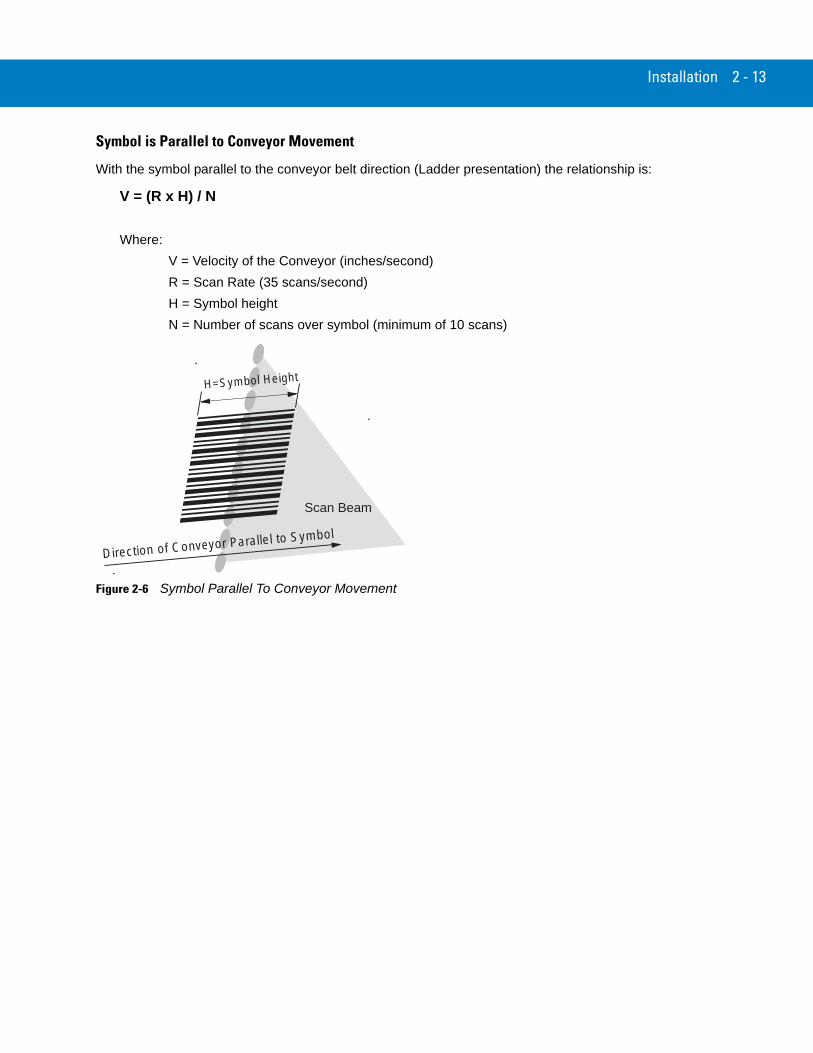
Conveyor applications require that the conveyor velocity be set to optimize the scan engines ability to read symbols. The orientation of the symbol with respect to the conveyor direction is another consideration. Figure 2-5 on page 2-12 illustrates the relationship of the conveyor velocity with respect to a symbol positioned perpendicular to the conveyor direction and Figure 2-6 on page 2-13 illustrates the relationship of the conveyor velocity with respect to a symbol positioned parallel to the conveyor direction.
Symbol is Perpendicular to Conveyor Movement
With the symbol perpendicular to the conveyor belt direction (Picket Fence presentation) the relationship is:
V = (R x (F-W) / N
Where: V = Velocity of the Conveyor (inches/second)R = Scan Rate (35 scans/second)F = Field Width of Scan BeamW = Symbol Width (inches)N = Number of scans over symbol (minimum of 10 scans)
Figure 2-5 Symbol Perpendicular To Conveyor Movement
Scan Beam
Direction of Conveyor Perpendicular to Symbol
W=Symbol Width
F=Field Width
Installation 2 - 13
Symbol is Parallel to Conveyor Movement
With the symbol parallel to the conveyor belt direction (Ladder presentation) the relationship is:
V = (R x H) / N
Where:V = Velocity of the Conveyor (inches/second)R = Scan Rate (35 scans/second)H = Symbol heightN = Number of scans over symbol (minimum of 10 scans)
Figure 2-6 Symbol Parallel To Conveyor Movement
Scan Beam
Direction of Conveyor Parallel to Symbol
H=Symbol Height
2 - 14 Symbol SE1200 Series Scan Engine Integration Guide
AccessoriesTable 2-4 lists the available scan engine accessories.
Hardware Accessories
Table 2-5 lists the available hardware accessories for the scan engine.
Table 2-4 Accessories
Accessory Part Number
Flex Strip, undecoded only (8-pin fanout) 15-81327-01
Flex Strip Variable Length, undecoded only (8-pin fanout) 15-09306-01
8-pin Connector 50-12171-008
Table 2-5 Hardware Accessories
Company Discipline Specifics
Tower Fasteners Co., Inc.1690 North Ocean Ave.Holtsville, New York 11742-1823(516) 289-8800
Fasteners Metallic, non-magnetic screws
Installation 2 - 15
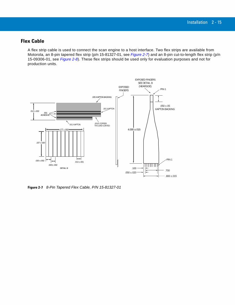
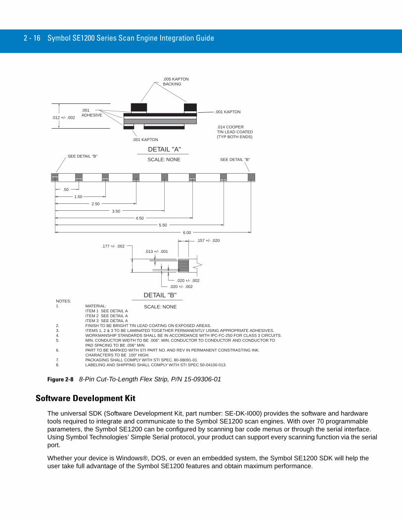
Flex Cable
A flex strip cable is used to connect the scan engine to a host interface. Two flex strips are available from Motorola, an 8-pin tapered flex strip (p/n 15-81327-01, see Figure 2-7) and an 8-pin cut-to-length flex strip (p/n 15-09306-01, see Figure 2-8). These flex strips should be used only for evaluation purposes and not for production units.
Figure 2-7 8-Pin Tapered Flex Cable, P/N 15-81327-01
.100.700
.050 ±.020.800 ±.015
.050 ±.05 KAPTON BACKING
EXPOSED FINGERSSEE DETAIL B(NEARSIDE)
4.000 ±.015
EXPOSED FINGERS
PIN 1
PIN 1
.005 KAPTON BACKING
.001 KAPTON
.0014 COPPERTIN LEAD COATED.001 KAPTON
.001 ADHESIVE
.157 ±.020
.020 ±.002 .013 ±.001.020 .002
.177 ±.002
DETAIL B
.012 ±.002
±
2 - 16 Symbol SE1200 Series Scan Engine Integration Guide
Figure 2-8 8-Pin Cut-To-Length Flex Strip, P/N 15-09306-01
Software Development Kit
The universal SDK (Software Development Kit, part number: SE-DK-I000) provides the software and hardware tools required to integrate and communicate to the Symbol SE1200 scan engines. With over 70 programmable parameters, the Symbol SE1200 can be configured by scanning bar code menus or through the serial interface. Using Symbol Technologies’ Simple Serial protocol, your product can support every scanning function via the serial port.
Whether your device is Windows®, DOS, or even an embedded system, the Symbol SE1200 SDK will help the user take full advantage of the Symbol SE1200 features and obtain maximum performance.
NOTES:1. MATERIAL:
ITEM 1 SEE DETAIL AITEM 2 SEE DETAIL AITEM 3 SEE DETAIL A
2. FINISH TO BE BRIGHT TIN LEAD COATING ON EXPOSED AREAS.3. ITEMS 1, 2 & 3 TO BE LAMINATED TOGETHER PERMANENTLY USING APPROPRIATE ADHESIVES.4. WORKMANSHIP STANDARDS SHALL BE IN ACCORDANCE WITH IPC-FC-250 FOR CLASS 3 CIRCUITS.5. MIN. CONDUCTOR WIDTH TO BE .006". MIN. CONDUCTOR TO CONDUCTOR AND CONDUCTOR TO
PAD SPACING TO BE .006" MIN.6. PART TO BE MARKED WITH STI PART NO. AND REV IN PERMANENT CONSTRASTING INK.
CHARACTERS TO BE .100" HIGH.7. PACKAGING SHALL COMPLY WITH STI SPEC. 80-08091-01.8. LABELING AND SHIPPING SHALL COMPLY WITH STI SPEC 50-04100-013.
SCALE: NONE
DETAIL "B"
SCALE: NONE
DETAIL "A"
.001ADHESIVE
.014 COOPERTIN LEAD COATED (TYP BOTH ENDS)
6.00
5.50
4.50
3.50
2.50
1.50
.50
SEE DETAIL "B"SEE DETAIL "B"
.005 KAPTONBACKING
.177 +/- .002
.020 +/- .002
.157 +/- .020
.020 +/- .002
.013 +/- .001
.001 KAPTON
.001 KAPTON.012 +/- .002

Installation 2 - 17
The SDK contains:
• Media CD
• Development Board
• User Documentation
• Power supply
• Cable.
Media CD
The Media CD provides the software and user documentation:
• Simple Serial Interface Header Files
• DOS Serial Communication Library and Source Code
• Windows Serial Communication Library and Source Code
• Simple Serial Interface Library and Source Code
• DOS and Windows Demo Programs and Source Code
• Library Documentation.
Development Board
The Development Board is useful for connecting the scan engine to your PC development workstation. Functions of the development board include:
• Conversion of the Symbol SE1200 CMOS Serial Output to RS-232
• Mounting location for Symbol SE1200 Scan Engine (any version)
• Beeper and LED drivers
• 9 pin RS-232 for connection to PC workstation
• Aim and Trigger Buttons
• Beeper
• 990Power, Decode, Low Power Mode LEDs
• Test Points.
User Documentation
The Integration Guide provides the detailed technical specifications for the scan engine.
Power Supply
Power supplies are available in either 110VAC or 220VAC.
Cable
The cable provides a connection between the development board and your PC workstation.
2 - 18 Symbol SE1200 Series Scan Engine Integration Guide
Chapter 3 Symbol SE1200HP-I10xA Specifications
IntroductionThis chapter provides the technical specifications for the High Performance, Symbol SE1200HP-I10xA (with Adaptive Logic) scan engine.
Chapter 1, provides the detailed Theory of Operation, including a discussion of the functional components and the electrical inputs.
Chapter 2, provides the detailed Installation Procedures, including mounting, positioning, minimum window dimensions and application discussions.
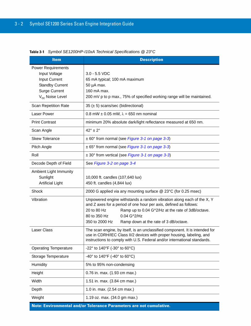
Technical SpecificationsTable 3-1 on page 3-2 provides the Symbol SE1200HP-I10xA technical specifications.
Electrical Interface
Table 1-1 on page 1-4 lists the pin functions of the scan engine interface for the Symbol SE1200HP-I10xA.
3 - 2 Symbol SE1200 Series Scan Engine Integration Guide
Table 3-1 Symbol SE1200HP-I10xA Technical Specifications @ 23°C
Item Description
Power RequirementsInput VoltageInput CurrentStandby CurrentSurge CurrentVcc Noise Level
3.0 - 5.5 VDC 65 mA typical; 100 mA maximum50 µA max.160 mA max.200 mV p to p max., 75% of specified working range will be maintained.
Scan Repetition Rate 35 (± 5) scans/sec (bidirectional)
Laser Power 0.8 mW ± 0.05 mW, λ = 650 nm nominal
Print Contrast minimum 20% absolute dark/light reflectance measured at 650 nm.
Scan Angle 42° ± 2°
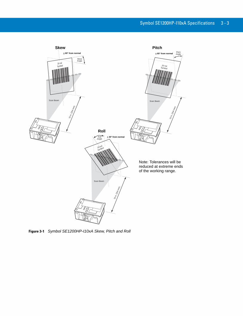
Skew Tolerance ± 60° from normal (see Figure 3-1 on page 3-3)
Pitch Angle ± 65° from normal (see Figure 3-1 on page 3-3)
Roll ± 30° from vertical (see Figure 3-1 on page 3-3)
Decode Depth of Field See Figure 3-2 on page 3-4
Ambient Light ImmunitySunlightArtificial Light
10,000 ft. candles (107,640 lux)450 ft. candles (4,844 lux)
Shock 2000 G applied via any mounting surface @ 23°C (for 0.25 msec)
Vibration Unpowered engine withstands a random vibration along each of the X, Y and Z axes for a period of one hour per axis, defined as follows:20 to 80 Hz Ramp up to 0.04 G^2/Hz at the rate of 3dB/octave.80 to 350 Hz 0.04 G^2/Hz350 to 2000 Hz Ramp down at the rate of 3 dB/octave.
Laser Class The scan engine, by itself, is an unclassified component. It is intended for use in CDRH/IEC Class II/2 devices with proper housing, labeling, and instructions to comply with U.S. Federal and/or international standards.
Operating Temperature -22° to 140°F (-30° to 60°C)
Storage Temperature -40° to 140°F (-40° to 60°C)
Humidity 5% to 95% non-condensing
Height 0.76 in. max. (1.93 cm max.)
Width 1.51 in. max. (3.84 cm max.)
Depth 1.0 in. max. (2.54 cm max.)
Weight 1.19 oz. max. (34.0 gm max.)
Note: Environmental and/or Tolerance Parameters are not cumulative.
Symbol SE1200HP-I10xA Specifications 3 - 3
Figure 3-1 Symbol SE1200HP-I10xA Skew, Pitch and Roll
Scan Beam
20 milSymbol
SkewAngle
10 in
. (25
4 m
m)
+ 60° from normal
Skew
Scan Beam
20 milSymbol
Pitch�Angle
10 in
. (25
4 m
m)
Pitch+ 65° from normal
Scan Beam
20 mil
Symbol
10 in
. (25
4 m
m)
RollAngle
Roll+ 30° from normal
Note: Tolerances will be
of the working range.reduced at extreme ends
3 - 4 Symbol SE1200 Series Scan Engine Integration Guide
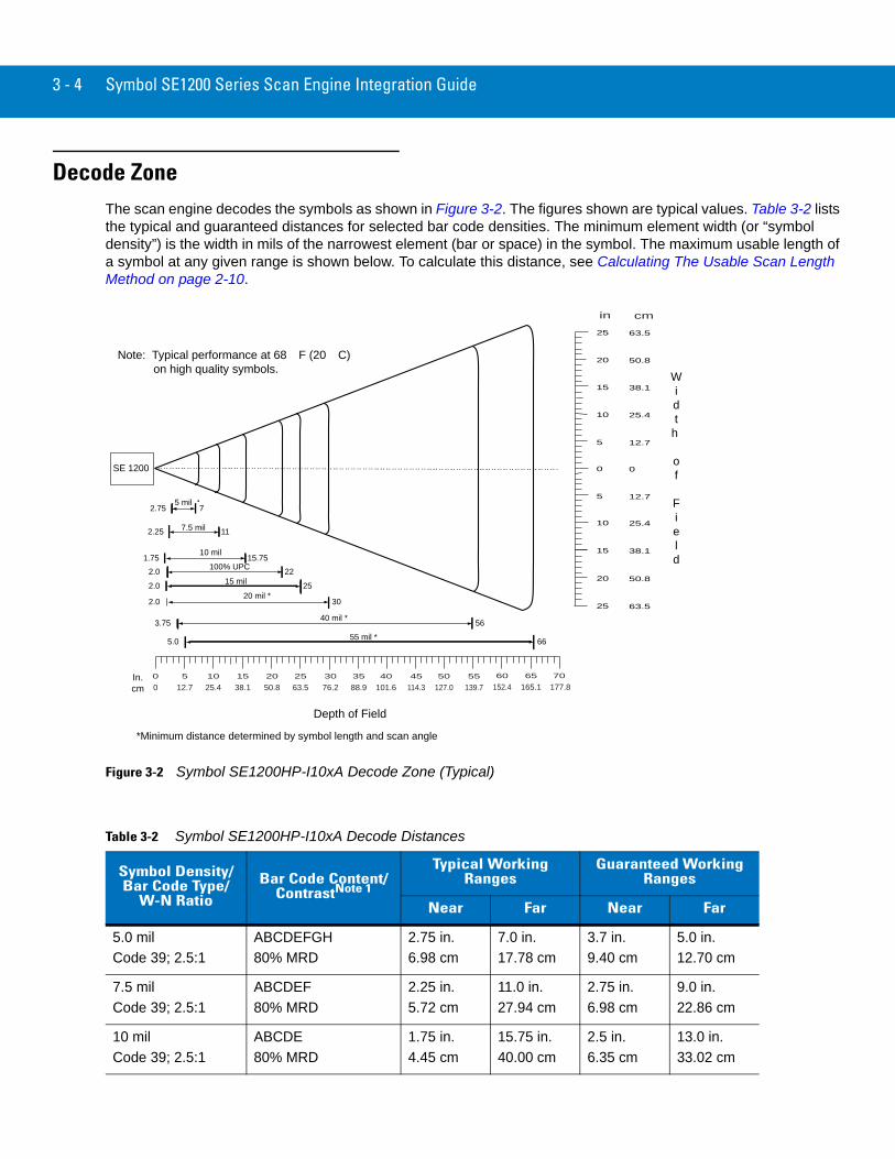
Decode ZoneThe scan engine decodes the symbols as shown in Figure 3-2. The figures shown are typical values. Table 3-2 lists the typical and guaranteed distances for selected bar code densities. The minimum element width (or “symbol density”) is the width in mils of the narrowest element (bar or space) in the symbol. The maximum usable length of a symbol at any given range is shown below. To calculate this distance, see Calculating The Usable Scan Length Method on page 2-10.
Figure 3-2 Symbol SE1200HP-I10xA Decode Zone (Typical)
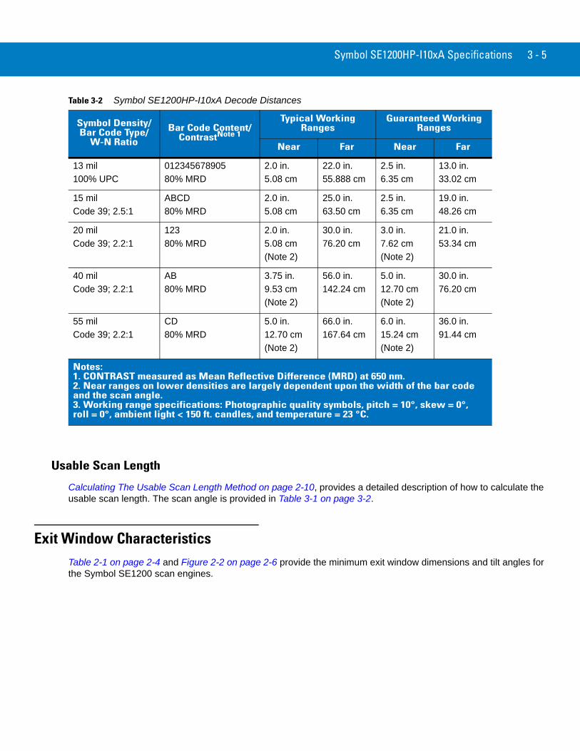
Table 3-2 Symbol SE1200HP-I10xA Decode Distances
Symbol Density/Bar Code Type/
W-N RatioBar Code Content/
ContrastNote 1
Typical Working Ranges
Guaranteed Working Ranges
Near Far Near Far
5.0 milCode 39; 2.5:1
ABCDEFGH80% MRD
2.75 in.6.98 cm
7.0 in.17.78 cm
3.7 in.9.40 cm
5.0 in.12.70 cm
7.5 milCode 39; 2.5:1
ABCDEF80% MRD
2.25 in.5.72 cm
11.0 in.27.94 cm
2.75 in.6.98 cm
9.0 in.22.86 cm
10 milCode 39; 2.5:1
ABCDE80% MRD
1.75 in.4.45 cm
15.75 in.40.00 cm
2.5 in.6.35 cm
13.0 in.33.02 cm
In.cm
SE 1200
5 mil2.75 7
7.5 mil
10 mil
2.25 11
15.75
15 mil 25
30
56
20 mil *
40 mil *
6655 mil *
*Minimum distance determined by symbol length and scan angle
Widt
h
of
Field
Depth of Field
Note: Typical performance at 68� F (20� C) on high quality symbols.
1.75
2.0
2.0
2.0
3.75
5.0
0
5
10
15
5
10
15
20
25
20
25
0
12.7
25.4
38.1
12.7
25.4
38.1
50.8
63.5
50.8
63.5
100% UPC 22
70
177.865
165.160
152.455
139.750
127.045
114.340
101.635
88.930
76.225
63.520
50.815
38.110
25.45
12.70
0
in cm
Symbol SE1200HP-I10xA Specifications 3 - 5
Usable Scan Length
Calculating The Usable Scan Length Method on page 2-10, provides a detailed description of how to calculate the usable scan length. The scan angle is provided in Table 3-1 on page 3-2.
Exit Window CharacteristicsTable 2-1 on page 2-4 and Figure 2-2 on page 2-6 provide the minimum exit window dimensions and tilt angles for the Symbol SE1200 scan engines.
13 mil100% UPC
01234567890580% MRD
2.0 in.5.08 cm
22.0 in.55.888 cm
2.5 in.6.35 cm
13.0 in.33.02 cm
15 milCode 39; 2.5:1
ABCD80% MRD
2.0 in.5.08 cm
25.0 in.63.50 cm
2.5 in.6.35 cm
19.0 in.48.26 cm
20 milCode 39; 2.2:1
12380% MRD
2.0 in.5.08 cm(Note 2)
30.0 in.76.20 cm
3.0 in.7.62 cm(Note 2)
21.0 in.53.34 cm
40 milCode 39; 2.2:1
AB80% MRD
3.75 in.9.53 cm(Note 2)
56.0 in.142.24 cm
5.0 in.12.70 cm(Note 2)
30.0 in.76.20 cm
55 milCode 39; 2.2:1
CD80% MRD
5.0 in.12.70 cm(Note 2)
66.0 in.167.64 cm
6.0 in.15.24 cm(Note 2)
36.0 in.91.44 cm
Notes:1. CONTRAST measured as Mean Reflective Difference (MRD) at 650 nm.2. Near ranges on lower densities are largely dependent upon the width of the bar code and the scan angle.3. Working range specifications: Photographic quality symbols, pitch = 10°, skew = 0°, roll = 0°, ambient light < 150 ft. candles, and temperature = 23 °C.
Table 3-2 Symbol SE1200HP-I10xA Decode Distances
Symbol Density/Bar Code Type/
W-N RatioBar Code Content/
ContrastNote 1
Typical Working Ranges
Guaranteed Working Ranges
Near Far Near Far

3 - 6 Symbol SE1200 Series Scan Engine Integration Guide
Chapter 4 Symbol SE1200WA-I200A Specifications
IntroductionThis chapter provides the technical specifications for the Symbol SE1200WA-I200A scan engine.
Chapter 1, provides the detailed Theory of Operation, including a discussion of the functional components and the electrical inputs.
Chapter 2, provides the detailed Installation Procedures, including mounting, positioning, minimum window dimensions and application discussions.
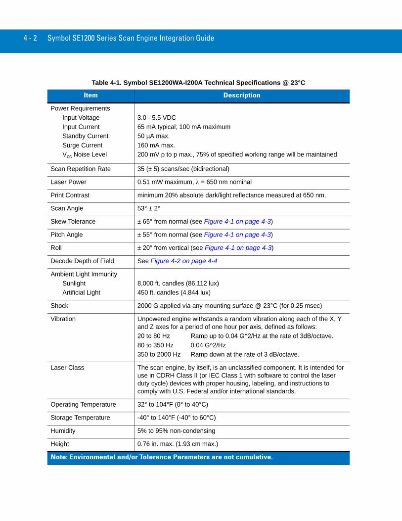
Technical SpecificationsTable 4-1 on page 4-5 provides the Symbol SE1200WA-I200A technical specifications.
Electrical Interface
Table 1-1 on page 1-4 lists the pin functions of the scan engine interface for the Symbol SE1200WA-I200A scan engine.
4 - 2 Symbol SE1200 Series Scan Engine Integration Guide
Table 4-1. Symbol SE1200WA-I200A Technical Specifications @ 23°C
Item Description
Power RequirementsInput VoltageInput CurrentStandby CurrentSurge CurrentVcc Noise Level
3.0 - 5.5 VDC 65 mA typical; 100 mA maximum50 µA max.160 mA max.200 mV p to p max., 75% of specified working range will be maintained.
Scan Repetition Rate 35 (± 5) scans/sec (bidirectional)
Laser Power 0.51 mW maximum, λ = 650 nm nominal
Print Contrast minimum 20% absolute dark/light reflectance measured at 650 nm.
Scan Angle 53° ± 2°
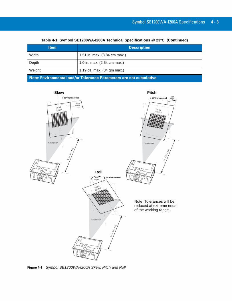
Skew Tolerance ± 65° from normal (see Figure 4-1 on page 4-3)
Pitch Angle ± 55° from normal (see Figure 4-1 on page 4-3)
Roll ± 20° from vertical (see Figure 4-1 on page 4-3)
Decode Depth of Field See Figure 4-2 on page 4-4
Ambient Light ImmunitySunlightArtificial Light
8,000 ft. candles (86,112 lux)450 ft. candles (4,844 lux)
Shock 2000 G applied via any mounting surface @ 23°C (for 0.25 msec)
Vibration Unpowered engine withstands a random vibration along each of the X, Y and Z axes for a period of one hour per axis, defined as follows:20 to 80 Hz Ramp up to 0.04 G^2/Hz at the rate of 3dB/octave.80 to 350 Hz 0.04 G^2/Hz350 to 2000 Hz Ramp down at the rate of 3 dB/octave.
Laser Class The scan engine, by itself, is an unclassified component. It is intended for use in CDRH Class II (or IEC Class 1 with software to control the laser duty cycle) devices with proper housing, labeling, and instructions to comply with U.S. Federal and/or international standards.
Operating Temperature 32° to 104°F (0° to 40°C)
Storage Temperature -40° to 140°F (-40° to 60°C)
Humidity 5% to 95% non-condensing
Height 0.76 in. max. (1.93 cm max.)
Note: Environmental and/or Tolerance Parameters are not cumulative.
Symbol SE1200WA-I200A Specifications 4 - 3
Figure 4-1 Symbol SE1200WA-I200A Skew, Pitch and Roll
Width 1.51 in. max. (3.84 cm max.)
Depth 1.0 in. max. (2.54 cm max.)
Weight 1.19 oz. max. (34 gm max.)
Table 4-1. Symbol SE1200WA-I200A Technical Specifications @ 23°C (Continued)
Item Description
Note: Environmental and/or Tolerance Parameters are not cumulative.
Scan Beam
20 milSymbol
SkewAngle
10 in
. (25
4 m
m)
+ 65° from normal
Skew
Scan Beam
20 milSymbol
Pitch�Angle
10 in
. (25
4 m
m)
Pitch+ 55° from normal
Scan Beam
20 mil
Symbol
10 in
. (25
4 m
m)
RollAngle
Roll+ 20° from normal
Note: Tolerances will be
of the working range.reduced at extreme ends
4 - 4 Symbol SE1200 Series Scan Engine Integration Guide
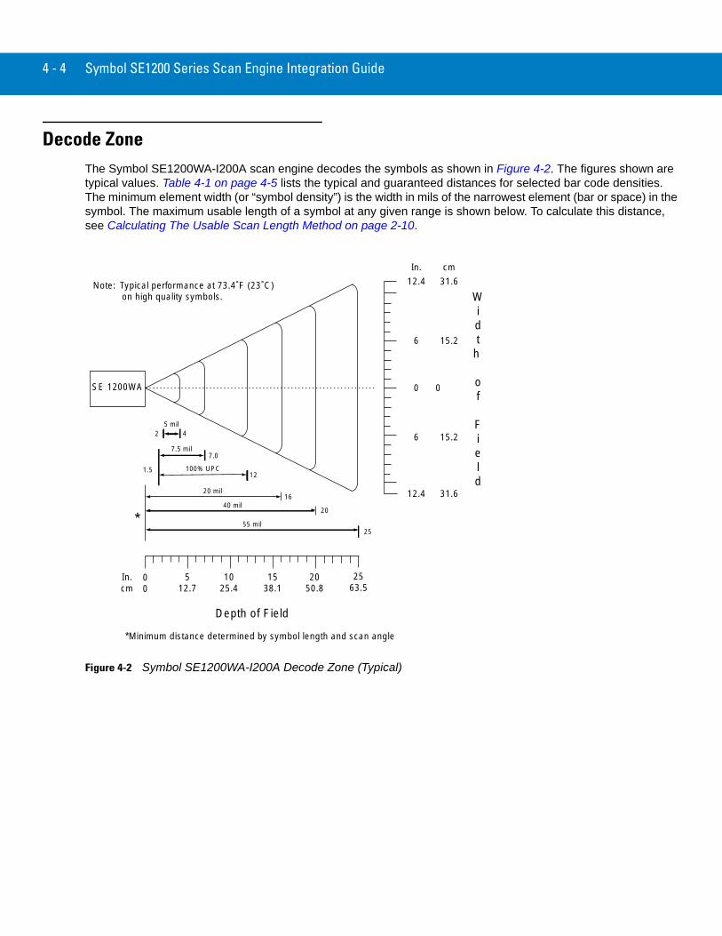
Decode ZoneThe Symbol SE1200WA-I200A scan engine decodes the symbols as shown in Figure 4-2. The figures shown are typical values. Table 4-1 on page 4-5 lists the typical and guaranteed distances for selected bar code densities. The minimum element width (or “symbol density”) is the width in mils of the narrowest element (bar or space) in the symbol. The maximum usable length of a symbol at any given range is shown below. To calculate this distance, see Calculating The Usable Scan Length Method on page 2-10.
Figure 4-2 Symbol SE1200WA-I200A Decode Zone (Typical)
In.cm
00
512.7
1025.4
1538.1
2050.8
2563.5
SE 1200WA
5 mil2 4
7.5 mil
100% UPC1.5
7.0
12
20 mil16
20
25
40 mil
55 mil*
*Minimum distance determined by symbol length and scan angle
Depth of Field
0
6
6
In. cm
Widt
h
of
Field
12.4
Note: Typical performance at 73.4˚F (23˚C) on high quality symbols.
12.4
0
15.2
15.2
31.6
31.6
Symbol SE1200WA-I200A Specifications 4 - 5
Usable Scan Length
Calculating The Usable Scan Length Method on page 2-10, provides a detailed description of how to calculate the usable scan length. The scan angle is provided in Table 4-1 on page 4-5.
Exit Window CharacteristicsTable 4-1 on page 4-5 and Figure 2-2 on page 2-6 provide the minimum exit window dimensions and tilt angles for the Symbol SE1200 scan engines.
Table 4-1 Symbol SE1200WA-I200A Decode Distances
Symbol Density/Bar Code Type
Bar Code Content/ContrastNote 1
Typical Working Ranges
Guaranteed Working Ranges
Near Far Near Far
5.0 milCode 39
ABCDEFGH80% MRD
2.0 in5.08 cm
4 in10.16 cm
2 in5.08 cm
4 in10.16 cm
7.5 milCode 39
ABCDEF80% MRD
1.5 in3.81 cm
7.0 in17.78 cm
1.5 in3.81 cm
7.0 in17.78 cm
13 mil100% UPC
01234567890580% MRD
1.5 in3.81 cm
12.0 in30.48 cm
1.5 in3.81 cm
10.0 in25.40 cm
20 milCode 39
12380% MRD
Note 2 16.0 in40.64 cm
Note 2 14.0 in35.56 cm
40 milCode 39
AB80% MRD
Note 2 20.0 in50.80 cm
Note 2 18.0 in45.72 cm
55 milCode 39
CD80% MRD
Note 2 25.0 in63.50 cm
Note 2 23.0 in58.42 cm
Notes:1. CONTRAST measured as Mean Reflective Difference (MRD) at 650 nm.2. Near ranges on lower densities (not specified) are largely dependent upon the width of the bar code and the scan angle.3. Working range specifications: Photographic quality symbols, pitch = 15°, skew = 0°, roll = 0°, ambient light < 150 ft. candles, and temperature = 23 °C

4 - 6 Symbol SE1200 Series Scan Engine Integration Guide
Chapter 5 Symbol SE1200VHD-I000A Specification
IntroductionThis chapter provides the technical specifications for the Symbol SE1200VHD-I000A (Very High Density) scan engine.
Chapter 1, provides the detailed Theory of Operation, including a discussion of the functional components and the electrical inputs.
Chapter 2, provides the detailed Installation Procedures, including mounting, positioning, minimum window dimensions and application discussions.
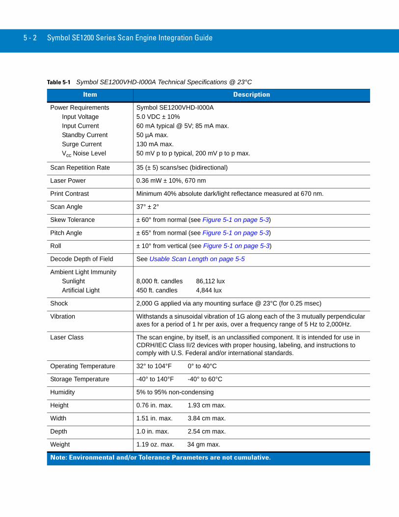
Symbol SE1200VHD-I000A Technical SpecificationsTable 5-1 on page 5-2 provides the Symbol SE1200VHD-I000A technical specifications.
Electrical Interface
Table 1-1 on page 1-4 lists the pin functions of the scan engine interface for the Symbol SE1200VHD-I000A scan engine.
5 - 2 Symbol SE1200 Series Scan Engine Integration Guide
Table 5-1 Symbol SE1200VHD-I000A Technical Specifications @ 23°C
Item Description
Power RequirementsInput VoltageInput CurrentStandby CurrentSurge CurrentVcc Noise Level
Symbol SE1200VHD-I000A5.0 VDC ± 10% 60 mA typical @ 5V; 85 mA max.50 µA max.130 mA max.50 mV p to p typical, 200 mV p to p max.
Scan Repetition Rate 35 (± 5) scans/sec (bidirectional)
Laser Power 0.36 mW ± 10%, 670 nm
Print Contrast Minimum 40% absolute dark/light reflectance measured at 670 nm.
Scan Angle 37° ± 2°
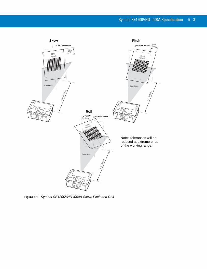
Skew Tolerance ± 60° from normal (see Figure 5-1 on page 5-3)
Pitch Angle ± 65° from normal (see Figure 5-1 on page 5-3)
Roll ± 10° from vertical (see Figure 5-1 on page 5-3)
Decode Depth of Field See Usable Scan Length on page 5-5
Ambient Light ImmunitySunlightArtificial Light
8,000 ft. candles 86,112 lux450 ft. candles 4,844 lux
Shock 2,000 G applied via any mounting surface @ 23°C (for 0.25 msec)
Vibration Withstands a sinusoidal vibration of 1G along each of the 3 mutually perpendicular axes for a period of 1 hr per axis, over a frequency range of 5 Hz to 2,000Hz.
Laser Class The scan engine, by itself, is an unclassified component. It is intended for use in CDRH/IEC Class II/2 devices with proper housing, labeling, and instructions to comply with U.S. Federal and/or international standards.
Operating Temperature 32° to 104°F 0° to 40°C
Storage Temperature -40° to 140°F -40° to 60°C
Humidity 5% to 95% non-condensing
Height 0.76 in. max. 1.93 cm max.
Width 1.51 in. max. 3.84 cm max.
Depth 1.0 in. max. 2.54 cm max.
Weight 1.19 oz. max. 34 gm max.
Note: Environmental and/or Tolerance Parameters are not cumulative.
Symbol SE1200VHD-I000A Specification 5 - 3
Figure 5-1 Symbol SE1200VHD-I000A Skew, Pitch and Roll
Scan Beam
20 milSymbol
SkewAngle
10 in
. (25
4 m
m)
+ 60° from normal
Skew
Scan Beam
20 milSymbol
Pitch�Angle
10 in
. (25
4 m
m)
Pitch+ 65° from normal
Scan Beam
20 mil
Symbol
10 in
. (25
4 m
m)
RollAngle
Roll+ 10° from normal
Note: Tolerances will be
of the working range.reduced at extreme ends
5 - 4 Symbol SE1200 Series Scan Engine Integration Guide
Symbol SE1200VHD-I000A Decode Zone (Vcc = 5V)
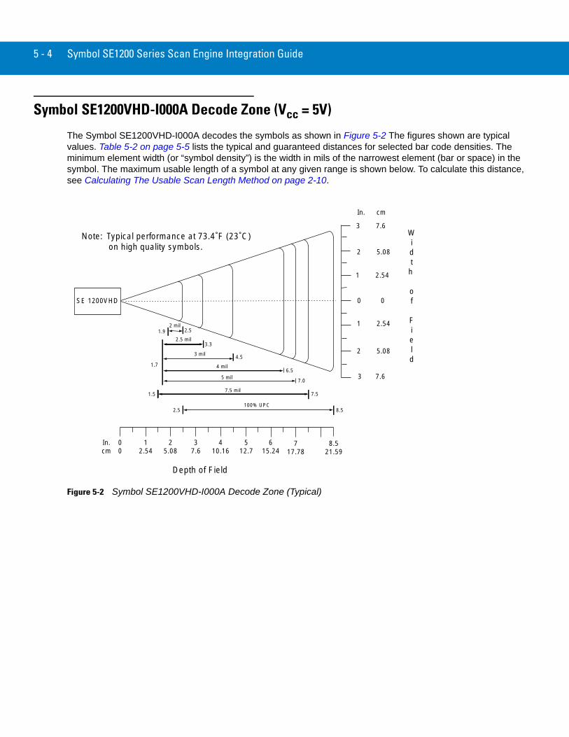
The Symbol SE1200VHD-I000A decodes the symbols as shown in Figure 5-2 The figures shown are typical values. Table 5-2 on page 5-5 lists the typical and guaranteed distances for selected bar code densities. The minimum element width (or “symbol density”) is the width in mils of the narrowest element (bar or space) in the symbol. The maximum usable length of a symbol at any given range is shown below. To calculate this distance, see Calculating The Usable Scan Length Method on page 2-10.
Figure 5-2 Symbol SE1200VHD-I000A Decode Zone (Typical)
In.cm
00
12.54
37.6
25.08
410.16
SE 1200VHD
1.7
100% UPC
3 mil
5 mil
7.5
8.5
7.5 mil
Depth of Field
0 0
1 2.54
In. cm
Width
of
Field
512.7
615.24
8.521.59
3 7.6
1 2.54
2 5.08
2 5.08
4 mil6.5
3.32.5 mil
Note: Typical performance at 73.4˚F (23˚C) on high quality symbols.
3 7.6
717.78
2.5
1.5
7.0
4.5
2 mil1.9 2.5
Symbol SE1200VHD-I000A Specification 5 - 5
The decode zone is a function of various symbol characteristics including density, print contrast, wide-to-narrow ratio, and edge acuity. Width of decode zone at any given distance must be considered when designing a system.
Usable Scan Length
Calculating The Usable Scan Length Method on page 2-10, provides a detailed description of how to calculate the usable scan length. The scan angle is provided in Table 5-1 on page 5-2.
Exit Window CharacteristicsTable 2-1 on page 2-4 and Figure 2-2 on page 2-6 provide the minimum exit window dimensions and tilt angles for the Symbol SE1200 scan engines.
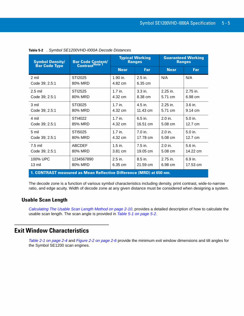
Table 5-2 . Symbol SE1200VHD-I000A Decode Distances
Symbol Density/Bar Code Type
Bar Code Content/ContrastNote 1
Typical Working Ranges
Guaranteed Working Ranges
Near Far Near Far
2 milCode 39; 2.5:1
STI202580% MRD
1.90 in.4.82 cm
2.5 in.6.35 cm
N/A N/A
2.5 milCode 39; 2.5:1
STI252580% MRD
1.7 in.4.32 cm
3.3 in.8.38 cm
2.25 in.5.71 cm
2.75 in.6.98 cm
3 milCode 39; 2.5:1
STI302580% MRD
1.7 in.4.32 cm
4.5 in.11.43 cm
2.25 in.5.71 cm
3.6 in.9.14 cm
4 milCode 39; 2.5:1
STI402285% MRD
1.7 in.4.32 cm
6.5 in.16.51 cm
2.0 in.5.08 cm
5.0 in.12.7 cm
5 milCode 39; 2.5:1
STI502580% MRD
1.7 in.4.32 cm
7.0 in.17.78 cm
2.0 in.5.08 cm
5.0 in.12.7 cm
7.5 milCode 39; 2.5:1
ABCDEF80% MRD
1.5 in.3.81 cm
7.5 in.19.05 cm
2.0 in.5.08 cm
5.6 in.14.22 cm
100% UPC13 mil
123456789080% MRD
2.5 in.6.35 cm
8.5 in.21.59 cm
2.75 in.6.98 cm
6.9 in.17.53 cm
1. CONTRAST measured as Mean Reflective Difference (MRD) at 650 nm.

5 - 6 Symbol SE1200 Series Scan Engine Integration Guide
Chapter 6 Symbol SE1200LR-I001A Specification
IntroductionThis chapter provides the technical specifications for the Symbol SE1200LR-I001A (Long Range) scan engine.
Chapter 1, provides the detailed Theory of Operation, including a discussion of the functional components and the electrical inputs.
Chapter 2, provides the detailed Installation Procedures, including mounting, positioning, minimum window dimensions and application discussions.
Symbol SE1200LR-I001A Technical SpecificationsTable 6-1 on page 6-2 provides the Symbol SE1200LR-I001A technical specifications.
Electrical Interface
Table 1-1 on page 1-4 lists the pin functions of the scan engine interface for the Symbol SE1200LR-I001A scan engine.
6 - 2 Symbol SE1200 Series Scan Engine Integration Guide
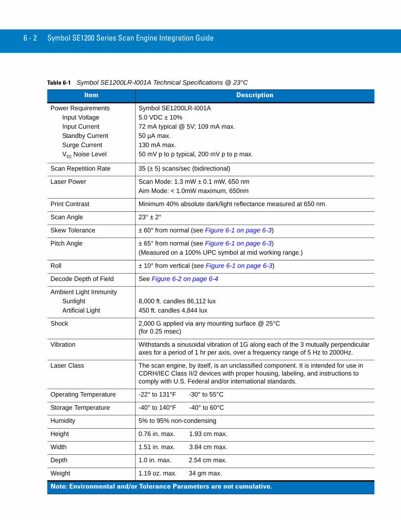
Table 6-1 Symbol SE1200LR-I001A Technical Specifications @ 23°C
Item Description
Power RequirementsInput VoltageInput CurrentStandby CurrentSurge CurrentVcc Noise Level
Symbol SE1200LR-I001A5.0 VDC ± 10% 72 mA typical @ 5V; 109 mA max.50 µA max.130 mA max.50 mV p to p typical, 200 mV p to p max.
Scan Repetition Rate 35 (± 5) scans/sec (bidirectional)
Laser Power Scan Mode: 1.3 mW ± 0.1 mW, 650 nmAim Mode: < 1.0mW maximum, 650nm
Print Contrast Minimum 40% absolute dark/light reflectance measured at 650 nm.
Scan Angle 23° ± 2°
Skew Tolerance ± 60° from normal (see Figure 6-1 on page 6-3)
Pitch Angle ± 65° from normal (see Figure 6-1 on page 6-3)(Measured on a 100% UPC symbol at mid working range.)
Roll ± 10° from vertical (see Figure 6-1 on page 6-3)
Decode Depth of Field See Figure 6-2 on page 6-4
Ambient Light ImmunitySunlightArtificial Light
8,000 ft. candles 86,112 lux450 ft. candles 4,844 lux
Shock 2,000 G applied via any mounting surface @ 25°C (for 0.25 msec)
Vibration Withstands a sinusoidal vibration of 1G along each of the 3 mutually perpendicular axes for a period of 1 hr per axis, over a frequency range of 5 Hz to 2000Hz.
Laser Class The scan engine, by itself, is an unclassified component. It is intended for use in CDRH/IEC Class II/2 devices with proper housing, labeling, and instructions to comply with U.S. Federal and/or international standards.
Operating Temperature -22° to 131°F -30° to 55°C
Storage Temperature -40° to 140°F -40° to 60°C
Humidity 5% to 95% non-condensing
Height 0.76 in. max. 1.93 cm max.
Width 1.51 in. max. 3.84 cm max.
Depth 1.0 in. max. 2.54 cm max.
Weight 1.19 oz. max. 34 gm max.
Note: Environmental and/or Tolerance Parameters are not cumulative.

Symbol SE1200LR-I001A Specification 6 - 3
Figure 6-1 Symbol SE1200LR-I001A Skew, Pitch and Roll
Scan Beam
20 milSymbol
SkewAngle
10 in
. (25
4 m
m)
+ 60° from normal
Skew
Scan Beam
20 milSymbol
Pitch�Angle
10 in
. (25
4 m
m)
Pitch+ 65° from normal
Scan Beam
20 mil
Symbol
10 in
. (25
4 m
m)
RollAngle
Roll+ 10° from normal
Note: Tolerances will be
of the working range.reduced at extreme ends
6 - 4 Symbol SE1200 Series Scan Engine Integration Guide
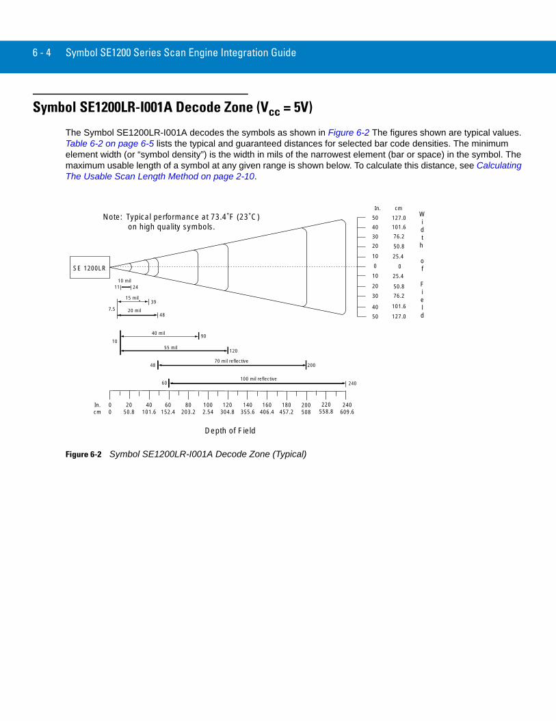
Symbol SE1200LR-I001A Decode Zone (Vcc = 5V)
The Symbol SE1200LR-I001A decodes the symbols as shown in Figure 6-2 The figures shown are typical values. Table 6-2 on page 6-5 lists the typical and guaranteed distances for selected bar code densities. The minimum element width (or “symbol density”) is the width in mils of the narrowest element (bar or space) in the symbol. The maximum usable length of a symbol at any given range is shown below. To calculate this distance, see Calculating The Usable Scan Length Method on page 2-10.
Figure 6-2 Symbol SE1200LR-I001A Decode Zone (Typical)
In.cm
00
40101.6
60152.4
80203.2
120304.8
160406.4
180457.2
240609.6
SE 1200LR
10 mil
7.5
39
20 mil
55 mil
90
120
70 mil reflective200
24060100 mil reflective
0
25.4
In. cmWidth
of
Field
Depth of Field
140355.6
1002.54
2050.8
50.8
76.2
11 24
15 mil
48
10
40 mil
48
30
20
10
0
25.4 10
50.820
76.230
101.640
127.050
101.6
50 127.0
40
Note: Typical performance at 73.4˚F (23˚C) on high quality symbols.
200508
220558.8
Symbol SE1200LR-I001A Specification 6 - 5
The decode zone is a function of various symbol characteristics including density, print contrast, wide to narrow ratio and edge acuity. Width of decode zone at any given distance must be considered when designing a system.
Usable Scan Length
Calculating The Usable Scan Length Method on page 2-10, provides a detailed description of how to calculate the usable scan length. The scan angle is provided in Table 6-1 on page 6-2.
Exit Window CharacteristicsTable 2-1 on page 2-4 and Figure 2-2 on page 2-6 provide the minimum exit window dimensions and tilt angles for the Symbol SE1200 scan engines.
Table 6-2 . Symbol SE1200LR-I001A Decode Distances
Symbol Density/Bar Code Type/
W-N RatioBar Code Content/
ContrastNote 1
Typical Working Ranges
Guaranteed Working Ranges
Near Far Near Far
10 milCode 39; 2.5:1
ABCDE80% MRD
11 in.27.94 cm
24 in.60.96 cm
15.5 in.39.37 cm
20 in.50.80 cm
15 milCode 39; 2.8:1
STI80% MRD
7.5 in.19.05 cm
39 in.99.06 cm
9 in.22.86 cm
34 in.86.36 cm
20 milCode 39; 2.2:1
12380% MRD
7.5 in.19.05 cm
48 in.121.92 cm
9 in.22.86 cm
39 in.99.06 cm
40 milCode 39; 2.2:1
AB80% MRD
10 in.25.40 cm
90 in.228.60 cm
10 in.25.40 cm
80 in.203.20 cm
55 milCode 39; 2.2:1
CD80% MRD
10 in.25.40 cm
120 in.304.80 cm
10 in.25.40 cm
90 in.228.60 cm
70 milNote 4
Code 39; 3.0:112347780% MRD
48 in.121.92 cm
200 in.508.00 cm
70 in.177.80 cm
162 in.411.48 cm
100 milNote 4
Code 39; 3.0:1123480% MRD
60 in.152.40 cm
240 in.609.60 cm
84 in.213.36 cm
210 in.533.40 cm
Notes:1. CONTRAST measured as Mean Reflective Difference (MRD) at 670 nm.2. Near ranges on lower densities (not specified) are largely dependent upon the width of the bar code and the scan angle.3. Working range specifications at ambient temperature (23 °C).4. Reflective Symbol.

6 - 6 Symbol SE1200 Series Scan Engine Integration Guide

Chapter 7 Symbol SE1200ALR-I000A Specification
IntroductionThis chapter provides the technical specifications for the Symbol SE1200ALR-I000A (Advanced Long Range) scan engine.
Chapter 1, provides the detailed Theory of Operation, including a discussion of the functional components and the electrical inputs.
Chapter 2, provides the detailed Installation Procedures, including mounting, positioning, minimum window dimensions and application discussions.
Symbol SE1200ALR-I000A Technical SpecificationsTable 7-1 on page 7-2 provides the Symbol SE1200ALR-I000A technical specifications.
Electrical Interface
Table 1-1 on page 1-4 lists the pin functions of the scan engine interface for the Symbol SE1200ALR-I000A scan engine.

7 - 2 Symbol SE1200 Series Scan Engine Integration Guide
Table 7-1 Symbol SE1200ALR-I000A Technical Specifications @ 23°C
Item Description
Power RequirementsInput VoltageInput CurrentStandby CurrentSurge CurrentVcc Noise Level
Symbol SE1200ALR-I000A5.0 VDC ± 10% 72 mA typical @ 5V; 110 mA max.50 µA max.130 mA max.50 mV p to p typical, 200 mV p to p max.
Scan Repetition Rate 35 (± 5) scans/sec (bidirectional)
Laser Power 1.5 mW ± 0.2 mW, 650 nm
Print Contrast Minimum 40% absolute dark/light reflectance measured at 650 nm.
Scan Angle 13° ± 2°
Skew Tolerance ± 30° from normal (see Figure 7-1 on page 7-3)
Pitch Angle ± 55° from normal (see Figure 7-1 on page 7-3)
Roll ± 10° from vertical (see Figure 7-1 on page 7-3)
Decode Depth of Field See Figure 7-2 on page 7-4
Ambient Light ImmunitySunlightArtificial Light
4,000 ft. candles 43,056 lux450 ft. candles 4,844 lux
Shock 2,000 G applied via any mounting surface @ 25°C (for 0.25 msec)
Vibration Withstands a sinusoidal vibration of 1G along each of the 3 mutually perpendicular axes for a period of 1 hr per axis, over a frequency range of 5 Hz to 2000Hz.
Laser Class The scan engine, by itself, is an unclassified component. It is intended for use in CDRH/IEC Class II/3A devices with proper housing, labeling, and instructions to comply with U.S. Federal and/or international standards.
Operating Temperature -22° to 131°F -30° to 55°C
Storage Temperature -40° to 140°F -40° to 60°C
Humidity 5% to 95% non-condensing
Height 0.76 in. max. 1.93 cm max.
Width 1.51 in. max. 3.84 cm max.
Depth 1.0 in. max. 2.54 cm max.
Weight 1.19 oz. max. 34 gm max.
Note: Environmental and/or Tolerance Parameters are not cumulative.

Symbol SE1200ALR-I000A Specification 7 - 3
Figure 7-1 Symbol SE1200ALR-I000A Skew, Pitch and Roll
Scan Beam
20 milSymbol
SkewAngle
10 in
. (25
4 m
m)
+ 30° from normal
Skew
Scan Beam
20 milSymbol
Pitch�Angle
10 in
. (25
4 m
m)
Pitch+ 55° from normal
Scan Beam
20 mil
Symbol
10 in
. (25
4 m
m)
RollAngle
Roll+ 10° from normal
Note: Tolerances will be
of the working range.reduced at extreme ends
7 - 4 Symbol SE1200 Series Scan Engine Integration Guide
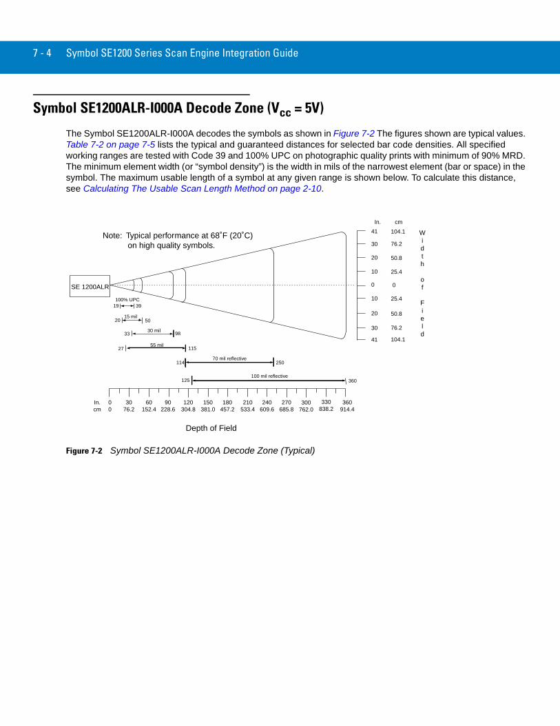
Symbol SE1200ALR-I000A Decode Zone (Vcc = 5V)
The Symbol SE1200ALR-I000A decodes the symbols as shown in Figure 7-2 The figures shown are typical values. Table 7-2 on page 7-5 lists the typical and guaranteed distances for selected bar code densities. All specified working ranges are tested with Code 39 and 100% UPC on photographic quality prints with minimum of 90% MRD. The minimum element width (or “symbol density”) is the width in mils of the narrowest element (bar or space) in the symbol. The maximum usable length of a symbol at any given range is shown below. To calculate this distance, see Calculating The Usable Scan Length Method on page 2-10.
Figure 7-2 Symbol SE1200ALR-I000A Decode Zone (Typical)
In.cm
00
60152.4
90228.6
120304.8
180457.2
240609.6
270685.8
360914.4
SE 1200ALR
100% UPC
20 50
55 mil
98
115
70 mil reflective250
360125100 mil reflective
0
25.4
In. cm
Width
of
Field
Depth of Field
210533.4
150381.0
3076.2
50.8
76.2
104.1
19 39
15 mil
3330 mil
114
41
30
20
10
0
25.4 10
50.820
76.230
104.141Note: Typical performance at 68˚F (20˚C) on high quality symbols.
300762.0
330838.2
27
Symbol SE1200ALR-I000A Specification 7 - 5
Usable Scan Length
Calculating The Usable Scan Length Method on page 2-10, provides a detailed description of how to calculate the usable scan length. The scan angle is provided in Table 7-1 on page 7-2.
Exit Window CharacteristicsTable 2-1 on page 2-4 and Figure 2-2 on page 2-6 provide the minimum exit window dimensions and tilt angles for the Symbol SE1200 scan engines.
Table 7-2 Symbol SE1200ALR-I000A Decode Distances
Symbol Density/Bar Code Type/
W-N RatioBar Code Content/
ContrastNote 1
Typical Working Ranges
Guaranteed Working Ranges
Near Far Near Far
13 mil100% UPC
123456789090% MRD
19.0 in48.26 cm
39.0 in99.06 cm
29.0 in73.66 cm
--
15 milCode 39; 2.8:1
STI90% MRD
20.0 in50.80 cm
50.0 in127.00 cm
24.0 in60.96 cm
45.0 in114.30 cm
30 milCode 39; 3.0:1
ABCDEFGHIJ90% MRD
33.0 in83.82 cm
98.0 in248.92 cm
42.0 in106.68 cm
90.0 in228.60 cm
55 milCode 39; 3.0:1
B90% MRD
27.0 in65.58 cm
115.0 in276.86 cm
--
101.0 in256.54 cm
70 milNote4
Code 39; 3.0:1
12347790% MRD
114.0 in289.56 cm
250.0 in635.00 cm
--
230.0 in584.20 cm
100 milNote 4
Code 39; 3.0:1
123490% MRD
125.0 in317.50 cm
360.0 in914.40 cm
--
324.0 in822.96 cm
Notes:1. CONTRAST measured as Mean Reflective Difference (MRD) at 650 nm.2. Near ranges on lower densities (not specified) are largely dependent upon the width of the bar code and the scan angle.3. Working range specifications at ambient temperature (23 °C)4. Reflective Symbol

7 - 6 Symbol SE1200 Series Scan Engine Integration Guide
Chapter 8 Regulatory Requirements
IntroductionThe sections that follow describe the integration, documentation, and labeling requirements for Class 1 and Class 2 laser products.
General Regulatory RequirementsWhen integrating the scan engines described in this guide, the following requirement must be met to maintain laser classification:
• The scan engine may not have the capability to be placed into AIM mode for more than 5 seconds continuously.
Required Documentation for Class 1 Laser ProductsThe documentation accompanying the end product should contain the following:
• “Complies with 21CFR1040.10 and 1040.11 except for deviations pursuant to Laser Notice No. 50, dated July 26, 2001. “
• “EN60825-1:1994+ A1:2002 +A2:2001”
• “IEC60825-1:1993+A1:1997+A2:2001”
• “Class 1 Laser devices are not considered to be hazardous when used for their intended purpose. The following statement is required to comply with US and international regulations:
CAUTION Use of controls, adjustments or performance of procedures other than those specified herein may result in hazardous laser light exposure.”.
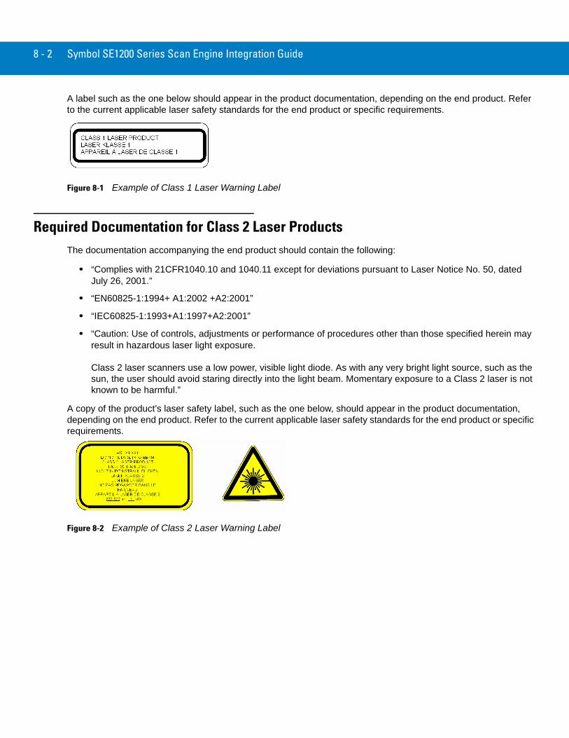
8 - 2 Symbol SE1200 Series Scan Engine Integration Guide
A label such as the one below should appear in the product documentation, depending on the end product. Refer to the current applicable laser safety standards for the end product or specific requirements.
Figure 8-1 Example of Class 1 Laser Warning Label
Required Documentation for Class 2 Laser ProductsThe documentation accompanying the end product should contain the following:
• “Complies with 21CFR1040.10 and 1040.11 except for deviations pursuant to Laser Notice No. 50, dated July 26, 2001.”
• “EN60825-1:1994+ A1:2002 +A2:2001”
• “IEC60825-1:1993+A1:1997+A2:2001”
• “Caution: Use of controls, adjustments or performance of procedures other than those specified herein may result in hazardous laser light exposure.
Class 2 laser scanners use a low power, visible light diode. As with any very bright light source, such as the sun, the user should avoid staring directly into the light beam. Momentary exposure to a Class 2 laser is not known to be harmful.”
A copy of the product’s laser safety label, such as the one below, should appear in the product documentation, depending on the end product. Refer to the current applicable laser safety standards for the end product or specific requirements.
Figure 8-2 Example of Class 2 Laser Warning Label
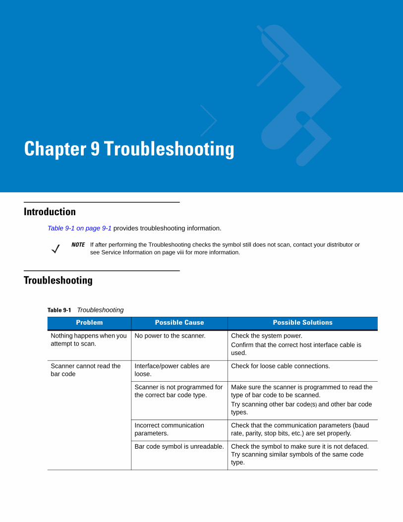
Chapter 9 Troubleshooting
IntroductionTable 9-1 on page 9-1 provides troubleshooting information.
Troubleshooting
NOTE If after performing the Troubleshooting checks the symbol still does not scan, contact your distributor or see Service Information on page viii for more information.
Table 9-1 Troubleshooting
Problem Possible Cause Possible Solutions
Nothing happens when you attempt to scan.
No power to the scanner. Check the system power.Confirm that the correct host interface cable is used.
Scanner cannot read the bar code
Interface/power cables are loose.
Check for loose cable connections.
Scanner is not programmed for the correct bar code type.
Make sure the scanner is programmed to read the type of bar code to be scanned.Try scanning other bar code(s) and other bar code types.
Incorrect communication parameters.
Check that the communication parameters (baud rate, parity, stop bits, etc.) are set properly.
Bar code symbol is unreadable. Check the symbol to make sure it is not defaced. Try scanning similar symbols of the same code type.

9 - 2 Symbol SE1200 Series Scan Engine Integration Guide
Glossary
AAperture. The opening in an optical system defined by a lens or baffle that establishes the field of view.
ASCII. American Standard Code for Information Interchange. A 7 bit-plus-parity code representing 128 letters, numerals, punctuation marks and control characters. It is a standard data transmission code in the U.S.
Autodiscrimination. The ability of an interface controller to determine the code type of a scanned bar code. After this determination is made, the information content is decoded.
BBar. The dark element in a printed bar code symbol.
Bar Code. A pattern of variable-width bars and spaces which represents numeric or alphanumeric data in machine-readable form. The general format of a bar code symbol consists of a leading margin, start character, data or message character, check character (if any), stop character, and trailing margin. Within this framework, each recognizable symbology uses its own unique format. See Symbology.
Bar Code Density. The number of characters represented per unit of measurement (e.g., characters per inch).
Bar Height. The dimension of a bar measured perpendicular to the bar width.
Bar Width. Thickness of a bar measured from the edge closest to the symbol start character to the trailing edge of the same bar.
Bit. Binary digit. One bit is the basic unit of binary information. Generally, eight consecutive bits compose one byte of data. The pattern of 0 and 1 values within the byte determines its meaning.
Bits per Second (bps). Bits transmitted or received.
Bluetooth. A technology that provides a way to connect and exchange information between devices such as scanners, mobile phones, laptops, PCs, and printers over a secure, globally unlicensed short-range radio frequency.
Glossary - 2 Symbol SE1200 Series Scan Engine Integration Guide
Boot or Boot-up. The process a computer goes through when it starts. During boot-up, the computer can run self-diagnostic tests and configure hardware and software.
bps. See Bits Per Second.
Byte. On an addressable boundary, eight adjacent binary digits (0 and 1) combined in a pattern to represent a specific character or numeric value. Bits are numbered from the right, 0 through 7, with bit 0 the low-order bit. One byte in memory is used to store one ASCII character.
CCDRH. Center for Devices and Radiological Health. A federal agency responsible for regulating laser product safety. This
agency specifies various laser operation classes based on power output during operation.
CDRH Class 1. This is the lowest power CDRH laser classification. This class is considered intrinsically safe, even if all laser output were directed into the eye's pupil. There are no special operating procedures for this class.
CDRH Class 2. No additional software mechanisms are needed to conform to this limit. Laser operation in this class poses no danger for unintentional direct human exposure.
Character. A pattern of bars and spaces which either directly represents data or indicates a control function, such as a number, letter, punctuation mark, or communications control contained in a message.
Character Set. Those characters available for encoding in a particular bar code symbology.
Check Digit. A digit used to verify a correct symbol decode. The scanner inserts the decoded data into an arithmetic formula and checks that the resulting number matches the encoded check digit. Check digits are required for UPC but are optional for other symbologies. Using check digits decreases the chance of substitution errors when a symbol is decoded.
Codabar. A discrete self-checking code with a character set consisting of digits 0 to 9 and six additional characters: ( - $ : / , +).
Code 128. A high density symbology which allows the controller to encode all 128 ASCII characters without adding extra symbol elements.
Code 3 of 9 (Code 39). A versatile and widely used alphanumeric bar code symbology with a set of 43 character types, including all uppercase letters, numerals from 0 to 9 and 7 special characters (- . / + % $ and space). The code name is derived from the fact that 3 of 9 elements representing a character are wide, while the remaining 6 are narrow.
Code 93. An industrial symbology compatible with Code 39 but offering a full character ASCII set and a higher coding density than Code 39.
Code Length. Number of data characters in a bar code between the start and stop characters, not including those characters.
Cold Boot. A cold boot restarts a computer and closes all running programs.
COM Port. Communication port; ports are identified by number, e.g., COM1, COM2.
Glossary - 3
Continuous Code. A bar code or symbol in which all spaces within the symbol are parts of characters. There are no intercharacter gaps in a continuous code. The absence of gaps allows for greater information density.
Cradle. A cradle is used for charging the terminal battery and for communicating with a host computer, and provides a storage place for the terminal when not in use.
DDead Zone. An area within a scanner's field of view, in which specular reflection may prevent a successful decode.
Decode. To recognize a bar code symbology (e.g., UPC/EAN) and then analyze the content of the specific bar code scanned.
Decode Algorithm. A decoding scheme that converts pulse widths into data representation of the letters or numbers encoded within a bar code symbol.
Decryption. Decryption is the decoding and unscrambling of received encrypted data. Also see, Encryption and Key.
Depth of Field. The range between minimum and maximum distances at which a scanner can read a symbol with a certain minimum element width.
Discrete Code. A bar code or symbol in which the spaces between characters (intercharacter gaps) are not part of the code.
Discrete 2 of 5. A binary bar code symbology representing each character by a group of five bars, two of which are wide. The location of wide bars in the group determines which character is encoded; spaces are insignificant. Only numeric characters (0 to 9) and START/STOP characters may be encoded.
EEAN. European Article Number. This European/International version of the UPC provides its own coding format and
symbology standards. Element dimensions are specified metrically. EAN is used primarily in retail.
Element. Generic term for a bar or space.
Encoded Area. Total linear dimension occupied by all characters of a code pattern, including start/stop characters and data.
ENQ (RS-232). ENQ software handshaking is also supported for the data sent to the host.
ESD. Electro-Static Discharge
HHID. Human Interface Device. A Bluetooth host type.
Host Computer. A computer that serves other terminals in a network, providing such services as computation, database access, supervisory programs and network control.
Glossary - 4 Symbol SE1200 Series Scan Engine Integration Guide
Hz. Hertz; A unit of frequency equal to one cycle per second.
IIEC. International Electrotechnical Commission. This international agency regulates laser safety by specifying various laser
operation classes based on power output during operation.
IEC (825) Class 1. This is the lowest power IEC laser classification. Conformity is ensured through a software restriction of 120 seconds of laser operation within any 1000 second window and an automatic laser shutdown if the scanner's oscillating mirror fails.
Intercharacter Gap. The space between two adjacent bar code characters in a discrete code.
Interleaved 2 of 5. A binary bar code symbology representing character pairs in groups of five bars and five interleaved spaces. Interleaving provides for greater information density. The location of wide elements (bar/spaces) within each group determines which characters are encoded. This continuous code type uses no intercharacter spaces. Only numeric (0 to 9) and START/STOP characters may be encoded.
Interleaved Bar Code. A bar code in which characters are paired together, using bars to represent the first character and the intervening spaces to represent the second.
Input/Output Ports. I/O ports are primarily dedicated to passing information into or out of the terminal’s memory. Series 9000 mobile computers include Serial and USB ports.
I/O Ports. interface The connection between two devices, defined by common physical characteristics, signal characteristics, and signal meanings. Types of interfaces include RS-232 and PCMCIA.
KKey. A key is the specific code used by the algorithm to encrypt or decrypt the data. Also see, Encryption and Decrypting.
LLASER. Light Amplification by Stimulated Emission of Radiation.The laser is an intense light source. Light from a laser is
all the same frequency, unlike the output of an incandescent bulb. Laser light is typically coherent and has a high energy density.
Laser Diode. A gallium-arsenide semiconductor type of laser connected to a power source to generate a laser beam. This laser type is a compact source of coherent light.
Laser Scanner. A type of bar code reader that uses a beam of laser light.
LED Indicator. A semiconductor diode (LED - Light Emitting Diode) used as an indicator, often in digital displays. The semiconductor uses applied voltage to produce light of a certain frequency determined by the semiconductor's particular chemical composition.
Glossary - 5
Light Emitting Diode. See LED.
MMIL. 1 mil = 1 thousandth of an inch.
MIN. Mobile Identification Number. The unique account number associated with a cellular device. It is broadcast by the cellular device when accessing the cellular system.
Misread (Misdecode). A condition which occurs when the data output of a reader or interface controller does not agree with the data encoded within a bar code symbol.
MRD. Minimum reflective difference. A measurement of print contrast.
NNominal. The exact (or ideal) intended value for a specified parameter. Tolerances are specified as positive and negative
deviations from this value.
Nominal Size. Standard size for a bar code symbol. Most UPC/EAN codes are used over a range of magnifications (e.g., from 0.80 to 2.00 of nominal).
OODI. See Open Data-Link Interface.
Open Data-Link Interface (ODI). Novell’s driver specification for an interface between network hardware and higher-level protocols. It supports multiple protocols on a single NIC (Network Interface Controller). It is capable of understanding and translating any network information or request sent by any other ODI-compatible protocol into something a NetWare client can understand and process.
Open System Authentication. Open System authentication is a null authentication algorithm.
PPAN . Personal area network. Using Bluetooth wireless technology, PANs enable devices to communicate wirelessly.
Generally, a wireless PAN consists of a dynamic group of less than 255 devices that communicate within about a 33-foot range. Only devices within this limited area typically participate in the network.
Parameter. A variable that can have different values assigned to it.
Percent Decode. The average probability that a single scan of a bar code would result in a successful decode. In a well-designed bar code scanning system, that probability should approach near 100%.
Glossary - 6 Symbol SE1200 Series Scan Engine Integration Guide
Print Contrast Signal (PCS). Measurement of the contrast (brightness difference) between the bars and spaces of a symbol. A minimum PCS value is needed for a bar code symbol to be scannable. PCS = (RL - RD) / RL, where RL is the reflectance factor of the background and RD the reflectance factor of the dark bars.
Programming Mode. The state in which a scanner is configured for parameter values. See Scanning Mode.
QQuiet Zone. A clear space, containing no dark marks, which precedes the start character of a bar code symbol and follows
the stop character.
QWERTY. A standard keyboard commonly used on North American and some European PC keyboards. “QWERTY” refers to the arrangement of keys on the left side of the third row of keys.
RReflectance. Amount of light returned from an illuminated surface.
Resolution. The narrowest element dimension which is distinguished by a particular reading device or printed with a particular device or method.
RF. Radio Frequency.
RS-232. An Electronic Industries Association (EIA) standard that defines the connector, connector pins, and signals used to transfer data serially from one device to another.
SScan Area. Area intended to contain a symbol.
Scanner. An electronic device used to scan bar code symbols and produce a digitized pattern that corresponds to the bars and spaces of the symbol. Its three main components are: 1) Light source (laser or photoelectric cell) - illuminates a bar code,; 2) Photodetector - registers the difference in reflected light (more light reflected from spaces); 3) Signal conditioning circuit - transforms optical detector output into a digitized bar pattern.
Scanning Mode. The scanner is energized, programmed and ready to read a bar code.
Scanning Sequence. A method of programming or configuring parameters for a bar code reading system by scanning bar code menus.
Self-Checking Code. A symbology that uses a checking algorithm to detect encoding errors within the characters of a bar code symbol.
Space. The lighter element of a bar code formed by the background between bars.
Specular Reflection. The mirror-like direct reflection of light from a surface, which can cause difficulty decoding a bar code.

Glossary - 7
SPP. Serial Port Profile.
Start/Stop Character. A pattern of bars and spaces that provides the scanner with start and stop reading instructions and scanning direction. The start and stop characters are normally to the left and right margins of a horizontal code.
Substrate. A foundation material on which a substance or image is placed.
Symbol. A scannable unit that encodes data within the conventions of a certain symbology, usually including start/stop characters, quiet zones, data characters and check characters.
Symbol Aspect Ratio. The ratio of symbol height to symbol width.
Symbol Height. The distance between the outside edges of the quiet zones of the first row and the last row.
Symbol Length. Length of symbol measured from the beginning of the quiet zone (margin) adjacent to the start character to the end of the quiet zone (margin) adjacent to a stop character.
Symbology. The structural rules and conventions for representing data within a particular bar code type (e.g. UPC/EAN, Code 39, PDF417, etc.).
TTolerance. Allowable deviation from the nominal bar or space width.
UUPC. Universal Product Code. A relatively complex numeric symbology. Each character consists of two bars and two
spaces, each of which is any of four widths. The standard symbology for retail food packages in the United States.
VVisible Laser Diode (VLD). A solid state device which produces visible laser light.

Glossary - 8 Symbol SE1200 Series Scan Engine Integration Guide
Index
Aaccessories . . . . . . . . . . . . . . . . . . . . . . . . . . . . . . . 2-14
flex cable . . . . . . . . . . . . . . . . . . . . . . . . . . . . . . 2-15hardware . . . . . . . . . . . . . . . . . . . . . . . . . . . . . . 2-14software developer’s kit . . . . . . . . . . . . . . . . . . 2-16
analog signal processor . . . . . . . . . . . . . . . . . . . . . . . 1-3anti-reflection coaters . . . . . . . . . . . . . . . . . . . . . . . . 2-8
Bblock diagram . . . . . . . . . . . . . . . . . . . . . . . . . . . . . . 1-2bullets . . . . . . . . . . . . . . . . . . . . . . . . . . . . . . . . . . . . . . x
Ccommercially available coatings . . . . . . . . . . . . . . . . 2-8
anti-reflection . . . . . . . . . . . . . . . . . . . . . . . . . . . 2-8polysiloxane . . . . . . . . . . . . . . . . . . . . . . . . . . . . 2-8
control circuitry . . . . . . . . . . . . . . . . . . . . . . . . . . . . . 1-3conventions, notational . . . . . . . . . . . . . . . . . . . . . . . . . xconveyor belt velocity . . . . . . . . . . . . . . . . . . . . . . . 2-12
Ddecode zone
SE1200ALR-I000A . . . . . . . . . . . . . . . . . . . . . . . 7-4SE1200HP-I10xA . . . . . . . . . . . . . . . . . . . . . . . . 3-4SE1200LR-I001A . . . . . . . . . . . . . . . . . . . . . . . . 6-4SE1200VHD-I000A . . . . . . . . . . . . . . . . . . . . . . . 5-4SE1200WA-I200A . . . . . . . . . . . . . . . . . . . . . . . . 4-4
depth of fieldSE1200ALR-I000A . . . . . . . . . . . . . . . . . . . . . . . 7-2SE1200HP-I10xA . . . . . . . . . . . . . . . . . . . . . . . . 3-2SE1200LR-I001A . . . . . . . . . . . . . . . . . . . . . . . . 6-2SE1200VHD-I000A . . . . . . . . . . . . . . . . . . . . . . . 5-2SE1200WA-I200A . . . . . . . . . . . . . . . . . . . . . . . . 4-2
development board . . . . . . . . . . . . . . . . . . . . . . . . . 2-17cable . . . . . . . . . . . . . . . . . . . . . . . . . . . . . . . . . 2-17
digitizer . . . . . . . . . . . . . . . . . . . . . . . . . . . . . . . . . . . 1-3
Eelectrical interface . . . . . . . . . . . . . . . . . . . . . . . . . . . 1-4
SE1200ALR-I000A . . . . . . . . . . . . . . . . . . . . . . . 7-1SE1200HP-I10xA . . . . . . . . . . . . . . . . . . . . . . . . 3-1SE1200LR-I001A . . . . . . . . . . . . . . . . . . . . . . . . 6-1SE1200VHD-I000A . . . . . . . . . . . . . . . . . . . . . . . 5-1SE1200WA-I200A . . . . . . . . . . . . . . . . . . . . . . . 4-1
environment . . . . . . . . . . . . . . . . . . . . . . . . . . . . . . . 2-3ESD . . . . . . . . . . . . . . . . . . . . . . . . . . . . . . . . . . . . . . 2-3exit window . . . . . . . . . . . . . . . . . . . . . . . . . . . . . . . . 2-4exit window manufacturers . . . . . . . . . . . . . . . . . . . . 2-8
Fflex cable . . . . . . . . . . . . . . . . . . . . . . . . . . . . . . . . . 2-15
Ggrounding . . . . . . . . . . . . . . . . . . . . . . . . . . . . . . . . . 2-3
Hhousing design . . . . . . . . . . . . . . . . . . . . . . . . . . . . . 2-3
Iinformation, service . . . . . . . . . . . . . . . . . . . . . . . . . . . . xinstallation . . . . . . . . . . . . . . . . . . . . . . . . . . . . . . . . . 2-2
Llaser class
Index - 2 Symbol SE1200 Series Scan Engine Integration Guide
SE1200ALR-I000A . . . . . . . . . . . . . . . . . . . . . . . 7-2SE1200HP-I10xA . . . . . . . . . . . . . . . . . . . . . . . . 3-2SE1200LR-I001A . . . . . . . . . . . . . . . . . . . . . . . . 6-2SE1200VHD-I000A . . . . . . . . . . . . . . . . . . . . . . . 5-2SE1200WA-I200A . . . . . . . . . . . . . . . . . . . . . . . . 4-2
laser driver . . . . . . . . . . . . . . . . . . . . . . . . . . . . . . . . . 1-2laser power
SE1200ALR-I000A . . . . . . . . . . . . . . . . . . . . . . . 7-2SE1200HP-I10xA . . . . . . . . . . . . . . . . . . . . . . . . 3-2SE1200LR-I001A . . . . . . . . . . . . . . . . . . . . . . . . 6-2SE1200VHD-I000A . . . . . . . . . . . . . . . . . . . . . . . 5-2SE1200WA-I200A . . . . . . . . . . . . . . . . . . . . . . . . 4-2
location and positioning . . . . . . . . . . . . . . . . . . . . . . . 2-9
Mmedia CD . . . . . . . . . . . . . . . . . . . . . . . . . . . . . . . . . 2-17mounting . . . . . . . . . . . . . . . . . . . . . . . . . . . . . . . . . . 2-1
Nnotational conventions . . . . . . . . . . . . . . . . . . . . . . . . . . x
Ooperating temperature
SE1200ALR-I000A . . . . . . . . . . . . . . . . . . . . . . . 7-2SE1200HP-I10xA . . . . . . . . . . . . . . . . . . . . . . . . 3-2SE1200LR-I001A . . . . . . . . . . . . . . . . . . . . . . . . 6-2SE1200VHD-I000A . . . . . . . . . . . . . . . . . . . . . . . 5-2SE1200WA-I200A . . . . . . . . . . . . . . . . . . . . . . . . 4-2
optical . . . . . . . . . . . . . . . . . . . . . . . . . . . . . . . . . . . . 2-3avoiding scratched windows . . . . . . . . . . . . . . . . 2-6window material . . . . . . . . . . . . . . . . . . . . . . . . . 2-7
overview . . . . . . . . . . . . . . . . . . . . . . . . . . . . . . . . . . 1-1
Pphotodiode . . . . . . . . . . . . . . . . . . . . . . . . . . . . . . . . . 1-3pitch angle
SE1200ALR-I000A . . . . . . . . . . . . . . . . . . . . . . . 7-2SE1200HP-I10xA . . . . . . . . . . . . . . . . . . . . . . . . 3-2SE1200LR-I001A . . . . . . . . . . . . . . . . . . . . . . . . 6-2SE1200VHD-I000A . . . . . . . . . . . . . . . . . . . . . . . 5-2SE1200WA-I200A . . . . . . . . . . . . . . . . . . . . . . . . 4-2
positioning the window . . . . . . . . . . . . . . . . . . . . . . . 2-4power requirements
SE1200ALR-I000A . . . . . . . . . . . . . . . . . . . . . . . 7-2SE1200HP-I10xA . . . . . . . . . . . . . . . . . . . . . . . . 3-2SE1200LR-I001A . . . . . . . . . . . . . . . . . . . . . . . . 6-2SE1200VHD-I000A . . . . . . . . . . . . . . . . . . . . . . . 5-2SE1200WA-I200A . . . . . . . . . . . . . . . . . . . . . . . . 4-2
power supply . . . . . . . . . . . . . . . . . . . . . . . . . . . . . . 2-17print contrast
SE1200ALR-I000A . . . . . . . . . . . . . . . . . . . . . . . 7-2SE1200HP-I10xA . . . . . . . . . . . . . . . . . . . . . . . . 3-2SE1200LR-I001A . . . . . . . . . . . . . . . . . . . . . . . . 6-2SE1200VHD-I000A . . . . . . . . . . . . . . . . . . . . . . . 5-2SE1200WA-I200A . . . . . . . . . . . . . . . . . . . . . . . . 4-2
Rrange limiter mode . . . . . . . . . . . . . . . . . . . . . . . . . . . 1-2regulatory
required documentation . . . . . . . . . . . . . . . . . . . . 8-1roll
SE1200ALR-I000A . . . . . . . . . . . . . . . . . . . . . . . 7-2SE1200HP-I10xA . . . . . . . . . . . . . . . . . . . . . . . . 3-2SE1200LR-I001A . . . . . . . . . . . . . . . . . . . . . . . . 6-2SE1200VHD-I000A . . . . . . . . . . . . . . . . . . . . . . . 5-2SE1200WA-I200A . . . . . . . . . . . . . . . . . . . . . . . . 4-2
Sscan angle
SE1200ALR-I000A . . . . . . . . . . . . . . . . . . . . . . . 7-2SE1200HP-I10xA . . . . . . . . . . . . . . . . . . . . . . . . 3-2SE1200LR-I001A . . . . . . . . . . . . . . . . . . . . . . . . 6-2SE1200VHD-I000A . . . . . . . . . . . . . . . . . . . . . . . 5-2SE1200WA-I200A . . . . . . . . . . . . . . . . . . . . . . . . 4-2
scan repetition rateSE1200ALR-I000A . . . . . . . . . . . . . . . . . . . . . . . 7-2SE1200HP-I10xA . . . . . . . . . . . . . . . . . . . . . . . . 3-2SE1200LR-I001A . . . . . . . . . . . . . . . . . . . . . . . . 6-2SE1200VHD-I000A . . . . . . . . . . . . . . . . . . . . . . . 5-2SE1200WA-I200A . . . . . . . . . . . . . . . . . . . . . . . . 4-2
service information . . . . . . . . . . . . . . . . . . . . . . . . . . . . . xshock
SE1200ALR-I000A . . . . . . . . . . . . . . . . . . . . . . . 7-2SE1200HP-I10xA . . . . . . . . . . . . . . . . . . . . . . . . 3-2SE1200LR-I001A . . . . . . . . . . . . . . . . . . . . . . . . 6-2SE1200VHD-I000A . . . . . . . . . . . . . . . . . . . . . . . 5-2SE1200WA-I200A . . . . . . . . . . . . . . . . . . . . . . . . 4-2
skew toleranceSE1200ALR-I000A . . . . . . . . . . . . . . . . . . . . . . . 7-2SE1200HP-I10xA . . . . . . . . . . . . . . . . . . . . . . . . 3-2SE1200LR-I001A . . . . . . . . . . . . . . . . . . . . . . . . 6-2SE1200VHD-I000A . . . . . . . . . . . . . . . . . . . . . . . 5-2SE1200WA-I200A . . . . . . . . . . . . . . . . . . . . . . . . 4-2
skew, pitch and roll forSE1200ALR-I100A . . . . . . . . . . . . . . . . . . . . . . . 7-3SE1200HP-I10xA . . . . . . . . . . . . . . . . . . . . . . . . 3-3SE1200LR-I001A . . . . . . . . . . . . . . . . . . . . . . . . 6-3SE1200VHD-I000A . . . . . . . . . . . . . . . . . . . . . . . 5-3SE1200WA-I200A . . . . . . . . . . . . . . . . . . . . . . . . 4-3
software development kit . . . . . . . . . . . . . . . . . . . . . 2-16specular reflection . . . . . . . . . . . . . . . . . . . . . . . . . . . 2-9storage temperature
Index - 3
SE1200ALR-I000A . . . . . . . . . . . . . . . . . . . . . . . 7-2SE1200HP-I10xA . . . . . . . . . . . . . . . . . . . . . . . . 3-2SE1200LR-I001A . . . . . . . . . . . . . . . . . . . . . . . . 6-2SE1200VHD-I000A . . . . . . . . . . . . . . . . . . . . . . . 5-2SE1200WA-I200A . . . . . . . . . . . . . . . . . . . . . . . . 4-2
suggested window properties . . . . . . . . . . . . . . . . . . 2-7
Ttechnical specifications
SE1200ALR-I000A . . . . . . . . . . . . . . . . . . . . . . . 7-1SE1200HP-I10xA . . . . . . . . . . . . . . . . . . . . . . . . 3-1SE1200LR-I001A . . . . . . . . . . . . . . . . . . . . . . . . 6-1SE1200VHD-I000A . . . . . . . . . . . . . . . . . . . . . . . 5-1SE1200WA-I200A . . . . . . . . . . . . . . . . . . . . . . . . 4-1
theory of operation . . . . . . . . . . . . . . . . . . . . . . . . . . . 1-2analog signal processor . . . . . . . . . . . . . . . . . . . 1-3control circuitry . . . . . . . . . . . . . . . . . . . . . . . . . . 1-3digitizer . . . . . . . . . . . . . . . . . . . . . . . . . . . . . . . . 1-3laser driver . . . . . . . . . . . . . . . . . . . . . . . . . . . . . 1-2mirror assembly . . . . . . . . . . . . . . . . . . . . . . . . . 1-2motor driver . . . . . . . . . . . . . . . . . . . . . . . . . . . . . 1-3mylar motor . . . . . . . . . . . . . . . . . . . . . . . . . . . . . 1-2photodiode . . . . . . . . . . . . . . . . . . . . . . . . . . . . . 1-3visible laser diode . . . . . . . . . . . . . . . . . . . . . . . . 1-2
Uunpacking . . . . . . . . . . . . . . . . . . . . . . . . . . . . . . . . . 2-1
Vvibration
SE1200ALR-I000A . . . . . . . . . . . . . . . . . . . . . . . 7-2SE1200HP-I10xA . . . . . . . . . . . . . . . . . . . . . . . . 3-2SE1200LR-I001A . . . . . . . . . . . . . . . . . . . . . . . . 6-2SE1200VHD-I000A . . . . . . . . . . . . . . . . . . . . . . . 5-2SE1200WA-I200A . . . . . . . . . . . . . . . . . . . . . . . . 4-2
visible laser diode . . . . . . . . . . . . . . . . . . . . . . . . . . . 1-2
Wwindow material . . . . . . . . . . . . . . . . . . . . . . . . . . . . . 2-7
acrylic . . . . . . . . . . . . . . . . . . . . . . . . . . . . . . . . . 2-7CR-39 . . . . . . . . . . . . . . . . . . . . . . . . . . . . . . . . . 2-7

Index - 4 Symbol SE1200 Series Scan Engine Integration Guide

Tell Us What You Think...We’d like to know what you think about this Manual. Please take a moment to fill out this questionnaire and fax this form to: (631) 738-4618, or mail to:
Motorola, Inc.One Motorola Plaza M/S B-10Holtsville, NY 11742-1300 Attention: Technical Publications Manager
Advanced Data Capture Division
IMPORTANT: If you need product support, please call the appropriate customer support number provided. Unfortunately, we cannot provide customer support at the fax number above.
Manual Title:___________________________________________(please include revision level)
How familiar were you with this product before using this manual?
Did this manual meet your needs? If not, please explain.________________________________________________________________________________________________________________________________________________________________________________________________________________________________________________________________________________________________________________________________________________________
What topics need to be added to the index, if applicable? ________________________________________________________________________________________________________________________________________________________________________________________________________________________________________________________________________________________________________________________________________________________
What topics do you feel need to be better discussed? Please be specific.________________________________________________________________________________________________________________________________________________________________________________________________________________________________________________________________________________________________________________________________________________________
What can we do to further improve our manuals?________________________________________________________________________________________________________________________________________________________________________________________________________________________________________________________________________________________________________________________________________________________
Very familiar Slightly familiar Not at all familiar
Thank you for your input—We value your comments.


72E-58178-04 Revision A - February 2008
Motorola, Inc.One Motorola PlazaHoltsville, New York 11742, USA1-800-927-9626http://www.symbol.com
MOTOROLA and the Stylized M Logo and Symbol and the Symbol logo are registered in the U.S. Patent and Trademark Office. All other product or service names are the property of their registered owners. © Motorola, Inc. 2007