Embed Size (px)
Citation preview
Synchronization and Syntonization of Formation Flying Cubesats Using the Namuru V3.2
Spaceborne GPS Receiver
E. P. Glennon, J. P. Gauthier, M. Choudhury, and A. G. Dempster, The University of New South Wales K. Parkinson, General Dynamics Corporation Ltd
BIOGRAPHIES Dr Eamonn Glennon is a Senior Research Associate in the Department of Surveying and Geospatial Engineering within the School of Civil and Environmental Engineering, UNSW. He received a BSc, BE (Hons), MEngSc and a PhD in 1988, 1990, 2000 and 2010, respectively, all from UNSW. Before joining UNSW in 2010, he was a Principal Engineer (Algorithms) at SigNav Pty Ltd where he worked for 15 years on GPS embedded firmware and algorithm development. He also worked at Auspace Ltd for 3 years as a Software Systems Engineer.
Mr Joseph Gauthier is a Graduate Research Student at the School of Electrical Engineering and Telecommunications. He received a BSc in Aerospace Engineering (with High Honors) from the University of Texas at Austin in 2011. While an undergraduate student in Austin, he worked for two-and-a-half years at Applied Research Laboratories in the Space and Geophysics Laboratory on primarily the GPS Toolkit (GPSTk). His current research interest is precise timing with GPS.
Dr Mohammad Mazher-ul Alam Choudhury is a Research Associate at the Australian Centre for Space Engineering Research (ACSER) at University of New South Wales (UNSW). He holds a BE (Computer Science) degree from North South University, Bangladesh, an MSc in Computer Science from UNSW and recently graduated with a PhD from UNSW.
Mr Kevin Parkinson is the chief engineer at General Dynamics Corporation Ltd in New Zealand. He has completed many successful projects while working as an electronic engineer over the past 25 years since completing engineering studies. He is the designer of the UNSW Namuru GNSS receivers and is responsible for the design of new Namuru versions currently being developed for aerospace operations. His research interests include GNSS systems, FPGA design, embedded systems, low power RF design and signal processing.
Professor Andrew Dempster is Director of the Australian Centre for Space Engineering Research (ACSER) in the School of Electrical Engineering and Telecommunications at the University of New South Wales (UNSW). He has a BE and MEngSc from UNSW and a PhD from the University of Cambridge in efficient circuits for signal processing arithmetic. He was system
engineer and project manager for the first GPS receiver developed in Australia in the late 80s and has been involved in satellite navigation ever since. His current research interests are in satellite navigation receiver design and signal processing, areas where he has six patents, and new location technologies. He is leading the development of space engineering research at ACSER.
ABSTRACT The growing popularity of cubesats has delivered for the first time the opportunity to develop space missions at very low cost. These also include 2U and 3U cubesats, with the increased mass and volume of these larger formats allowing significantly enhanced capability. 3U cubesats can even include thrusters and reaction wheels in addition to the solar panels, batteries, telemetry and command and control systems that may be found on such platforms. The availability of small, cheap, and capable spacecraft, coupled with the fact the launchers often carry multiple cubesats for deployment presents the opportunity to fly pairs or triplets of satellites in formation, which may be beneficial in some applications, such as bistatic radar. This in turn requires a capability to not only fix the absolute and relative positions of the spacecraft, but depending on the mission may also require an ability to synchronize and syntonize them as well.
The Namuru V3.2 FPGA based GPS receiver has been developed specifically for the Boeing Colony II 3U cubesat platform and a mission that satisfies many of these requirements. In this paper, we focus on describing the timing synchronization and syntonization aspects of the receiver, with particular regard on how it may operate in low earth orbit (LEO). These timing aspects of the receiver include the use of disciplined voltage-controlled temperature-compensated crystal oscillators (VC-TCXOs) rather than ordinary TCXOs in order to eliminate sawtooth timing errors and to support the syntonization requirement. Algorithmic modifications necessary to account for the differences between the LEO and terrestrial scenarios are discussed. Finally, we also present results obtained by testing the navigation and timing outputs of the receiver using hardware based Spirent GPS simulators running LEO scenarios and high quality universal frequency counters/timers.
INTRODUCTION The development of spacecraft presents to the satellite designer a challenge that fully exercises the engineering process. Spacecraft are subject to constraints in almost every aspect of their design, including the allowable mass and volume of the device, as well as the power available during operation. Once launched, it is almost impossible to correct any deficiencies that may be encountered, so the reliability concerns are paramount. The spacecraft is required to operate in the harshest of environments, where extremes of temperature are regularly experienced, as well as experiencing radiation conditions that typically do not exist for terrestrial based equipment. As such, the inclusion of each component on a spacecraft is subject to the fullest consideration, where only components that are considered essential are included in the final design. It is also worth noting that many satellite missions are ‘one-off’ missions and as such, the benefits of economies of scale are rarely achieved.
Despite these obstacles, it is no surprise that inclusion of a GPS/GNSS receiver is now seen as an essential payload for many satellite missions. This follows because, as described in [1], inclusion of GPS allows precise orbit determination (POD) to be undertaken, as well as allowing the possibility of autonomous orbit control or even formation flying of spacecraft in cases where multiple satellites are being employed. Time synchronization is readily available as part of the position, velocity, and timing (PVT) solution performed by receiver, which may also be of use for providing position and time tagging for spacecraft imaging activities. More exotic earth observation (EO) functions may also be performed via GNSS Radio-Occultation (GNSS-RO) and GNSS Reflectometry (GNSS-R).
A recent trend in satellite engineering is the growing popularity of the CubeSat form-factor [2]. The format is made up of one unit cube size (1U) elements of dimensions 10 × 10 × 10 cm, although scaling in a single dimension is permitted thereby also allowing 2U or 3U satellites to be constructed. These larger formats are of particular interest as the increased volume allows for the inclusion of thrusters, reaction wheels and other scientific instruments in addition to the batteries, solar cells, flight computers and radio communications that are necessary for a useful satellite. Suppliers of cubesat components and engineering expertise are readily available [3] [4] and this has made the format ideal for teaching graduate students satellite engineering concepts, which was the original intent when cubesats were first proposed. However, the inherent cost advantages have also encouraged use of the format for scientific and specialized defense-related activities. The QB50 program [5] is an example of the former, while the Biarri program [6] is an example of the latter.
Although GPS receivers have long been available for spacecraft, few have the form-factor suitable for cubesats, and even fewer the form-factor suitable for the Boeing Colony II 3U cubesat [7]. One survey of suitable receivers
reveals that that the number of suitable receivers is quite limited [1]. One of two candidate receivers that stand out from this survey is the rebadged SigNav MG5001 receiver with custom firmware developed by their respective suppliers. This is sold as the Phoenix receiver by DLR and the SGR-05U receiver by Surrey Satellite Technology Limited (SSTL). However, the SigNav receivers are no longer manufactured and the GPS chipsets that were used for that product are no longer in production, meaning that the only supply is the pre-existing inventory held by those suppliers. Another possibility would be to try and get an existing OEM board supplier to remove the ITAR/Wassenaar-Arrangement speed restrictions from their receivers (with the appropriate paperwork) and to space qualify such a receiver. This was the solution employed by the CanX-2 design team, who flew a speed and height unrestricted Novatel OEM4-2GL receiver on their spacecraft [8]. The disadvantage of this solution is that the receiver hardware and software is never going to be optimized for the space environment, which can cause operational difficulties. Furthermore, it is often difficult to get the manufacturer to tailor their solution for the space-application because the sales volumes rarely justify the expense of doing so. It is also necessary to develop an appropriate interface board because the interfaces of the off-the-shelf OEM products rarely meet the requirements of the satellite bus.
In light of these facts, when the Australian Defence Science and Technology Organization (DSTO) invited the University of New South Wales (UNSW) to develop a GPS solution for the Biarri program, the result was a decision to develop a GPS receiver specific to the application. UNSWs participation in this program was directly related to its success in achieving an Australian Space Research Program (ASRP) grant for the ‘SAR Formation Flying’ project, which is currently being undertaken by the Australian Centre for Space Engineering Research (ACSER) at UNSW.
In this paper, we provide a short overview of the GPS requirements for the Biarri project, as well as describing the receiver itself. This is followed by a more detailed review of the receiver from a timing perspective, including a discussion of the hardware support for the timing application. The firmware aspects of the design are also covered because, as is the case with almost every complex embedded system, a significant portion of the solution lies in the firmware domain. Some of the practical difficulties experienced during the development process will also be discussed. Our final contribution is to describe the experiments we have performed to validate the receiver for the required application. These experiments have employed a Spirent hardware based GPS simulator that was used to provide a simulated orbit signals to a 2nd or 3rd generation prototype Namuru V3.2 receiver. The hardware and timing outputs of this receiver were then monitored and compared against the truth data available from the simulator, itself.
BIARRI PROJECT The Biarri project is a multi-lateral defense R&D program aimed at doing work in the area of space situational awareness (SSA) [6]. The project involves the launch of three Boeing Colony II cubesats in a string of pearls formation, where the cubesats are supplied, integrated and launched by the US. Each cubesat will contain a Namuru V3.2 GPS receiver and will incorporate a corner reflector to allow satellite laser ranging (SLR) to be undertaken by EOS Ltd, a Canberra based company with extensive expertise in this area. GPS receiver hardware design and manufacture has been undertaken by the New Zealand based company General Dynamics Corporation [9] (different from the multinational US defense conglomerate General Dynamics). The Namuru V3.2 firmware and field programmable gate array (FPGA) correlator design work has been done by UNSW and represent the Australian contribution to the program. It can be seen that this will permit experiments to be undertaken in which SLR positioning of the cubesat sized spacecraft is validated against the GPS based results. The UK is also involved in the program and is contributing a communications payload.
GPS RECEIVER REQUIREMENTS & DESIGN As is the case for defense related activities, the exact nature of the mission is not known by the authors. Nonetheless, we are able to describe some of the system requirements imposed on the GPS payload.
The first requirement is to calculate the position and velocity of the payload whilst in orbit, as well as to provide time synchronization signals, when required. The absolute positioning accuracy is required to be consistent with what can be expected from a single frequency L1 receiver, which in this case is within ±10 m RMS, while the time synchronization is required to be around the ±20 ns level. In addition to the absolute positioning requirement, there is also a relative positioning requirement to determine the relative positions of the spacecraft to within ±10 cm RMS. This can be achieved by using carrier phase processing, provided the spacing of the satellites is no more than approximately 10 km.
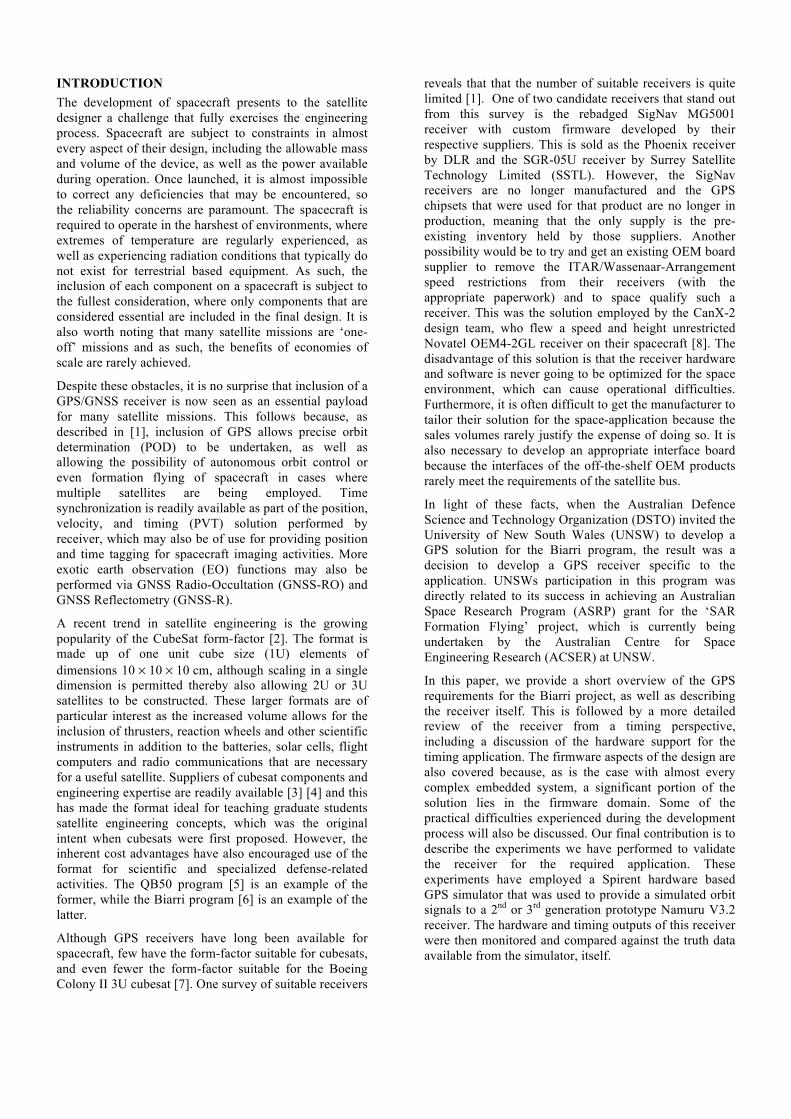
The Namuru V3.2 GPS receiver builds on a decade of FPGA GPS receiver development at UNSW, although the new design has been customised specifically for this application. Electrical interface and mechanical changes that make the payload suitable for the Colony II Bus (C2B) represent the most obvious customization to the user. Careful selection of component use has also occurred, including a change to MicroSemi (formerly Actel) FPGAs. These devices have the advantage of being flash-based and hence inherently more resistant to single event upsets (SEU) than equivalent SRAM based FPGAs, as supplied by Xilinx and Altera. The design also includes built-in latch-up detection to assist should a latch-up occur. A picture of the single-sided and populated Namuru V3.2 R3 printed-circuit-board (PCB) is shown in Figure 1.
However, these changes only represent the surface of the updates required. The GEC Plessey GPS architect firmware, which was previously used by Namuru, has now been completely replaced with the UNSW Aquarius GPS firmware. Aquarius not only includes specific modifications for the space environment, such as built-in two line element (TLE) SGP4 orbit estimators, but also includes many features that were not included in the GPS Architect, but would be considered as standard in a normal GPS receiver. Such features include the carrier-smoothed pseudoranges and Kalman filters for navigation, among other things. Further details on the Namuru V3.2 GPS receiver hardware and Aquarius firmware may be found in [10].
SYNCHRONIZATION & SYNTONIZATION HARDWARE IMPLEMENTATION Namuru V3.2 represents the first of the Namuru series of receivers that includes specific hardware support for timing applications. This support comes via the use of a voltage-controlled temperature-compensated crystal oscillator (VC-TCXO) rather than a standard TCXO, thereby permitting the receiver to be employed for syntonization applications, as well as allowing sawtooth timing errors to be eliminated. In this context, syntonization is defined as the alignment of clocks to the same frequency, while synchronization is a closely related and more familiar term that refers to the alignment of clocks at a particular time instant.
As an aside, it is interesting to note that timing represents one aspect of GPS receiver design that is not easily handled by software based receivers, despite the popularity of software based designs among the academic community. This doesn’t apply to real-time software-receivers able to interact with the RF front end in real-
Figure 1: Namuru V3.2A R3 GPS Receiver
time, although whether such receivers would be categorized as software-based receivers is questionable.
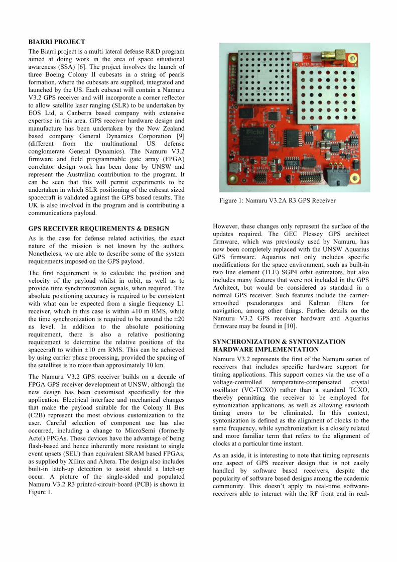
A GNSS receiver with a disciplined oscillator differs from a standard design in several respects. In addition to the use of a VC-TCXO, a means of supplying the analogue control voltages necessary to control the oscillator must be included. This is usually achieved using a digital-to-analog converter (DAC), together with an analog signal filter to ensure the quality of the control signal. This analog filter is of vital importance in the design as any noise not rejected by the filter directly affects the quality of the receiver clock and therefore the receiver’s measurements. The filter will typically require tuning to match the selected DAC. Because the control rate for the VC-TCXO is usually performed at a 1 Hz rate, it is not strictly necessary to use a multi-bit DAC as carefully filtered pulse-width-modulated (PWM) signals may suffice. Such signals are easily obtained using very simple digital counter logic. However, if PWM signals are used, particular care must be taken with the repetition rate of the PWM in order to avoid phase-noise spurs related to this repetition period. This introduces a trade-off because a longer period PWM signal effectively represents a higher resolution DAC, but also lowers the frequency of the phase-noise spurs, which may be unacceptable. The latest generation of the Namuru V3.2 receiver (V3.2 R3) has a build-time option for PWM control of the VC-TCXO, although at the time of writing this option remains untested. Instead, control of the VC-TCXO has been carried out using the built-in sigma-delta DAC that is already available within the Actel SmartFusion device.
These hardware concepts are illustrated in Figure 2, where Vdac is the output voltage from the DAC, Vcontrol is the VC-TCXO control voltage after low pass filtering, Fref is the reference oscillator frequency used by the GNSS radio, and IFsamples are the 2-bit intermediate frequency samples from the GNSS radio.
DISCIPLINED OSCILLATOR FIRMWARE MODIFICATIONS In addition to specific hardware modifications, a disciplined oscillator GNSS receiver also requires firmware modifications.
The first modification is to ensure that the VC-TCXO is properly initialized otherwise the time for initial acquisition of the satellite signals may be excessive. This initialization may be undertaken by assuming nominal transfer functions for each of the subsystems making up the control path, namely the DAC converter, the low pass filter, and the VC-TCXO. However, any deviations from the nominal will degrade the performance. Improvements on this may be achieved by storing the DAC control values from a previously successful run in non-volatile memory and using this value next time. Although the performance of the components, such as the VC-TCXO may be subject to aging, the stored values will adapt with this aging process, although care must be taken to ensure that only ‘good’ values are stored in this way. Failure to do so can result in the receiver never recovering from storage of a corrupted control value. A more sophisticated initialization may even take into account the temperature of the crystal, which might be possible if the system contains temperature sensors. Such a system would actively construct a crystal frequency offset versus temperature table during operation so that in the event that a position/velocity/time (PVT) solution is not available, a good estimate of the VC-TCXO frequency drift could still be provided. However, the Namuru V3.2 does not do this due to schedule constraints and the lack of this as a requirement, even though the required temperature sensors exist on the board.
The more important aspects of firmware modifications involve those changes necessary to implement the VC-TCXO control. Care must be taken when doing this because changes to the VC-TCXO will cause deterministic changes in the calculated receiver clock bias and receiver clock drift that won’t be consistent with normal crystal behaviour models, such as the Van Dierendonck model [11]. This can cause un-modeled clock errors to leak into position and velocity spaces causing excessive errors in the entire state vector. The key to solving this problem is to ensure that the effect of each applied change to the VC-TCXO control voltage is allowed to directly affect the clock-bias and clock- drift state vector elements inside the navigation Kalman filter.
The actual control process employs the receiver estimates of clock-bias ∆𝑡 and clock-drift ∆𝑡 from the PVT filter to actively adjust the SddValue value written to the SmartFusion DAC. Here, SddValue refers to the integer value used to set the output voltage of the DAC; it represents the “digital” control of DAC. Each new SddValue is determined from the current SddValue and the receiver’s ∆𝑡 and ∆𝑡 estimates. The calculation of the SddValue also takes into account the transfer functions of the DAC, the low pass filter, and the VC-TCXO.
In the case of the Namuru V3.2A R2 receiver, a large number of measurements were used to validate the calculated transfer functions for each of these subsystems. For the DAC, the measured performance was in close agreement with the published device specification and we simply used the theoretical results for the calculation, although the values are dependent on the selected
Figure 2: GNSS Receiver with Disciplined Oscillator
resolution for the sigma-delta DAC. However, in the case of the VC-TCXO, we found the manufacturer specifications less useful as they applied to a class of product whose actual specifications depended on the selected frequency. In this case, measuring the voltage-to-frequency gain of the device was quite useful, with the measured gain of 24,000 ppb/V differing substantially from the 8,000 ppb/V quoted on the datasheet. Similarly, it was also useful to measure the DC transfer function of the low pass filter because some parameters such as the input impedance of the VC-TCXO filter were unknown. It is worth noting that a high level of accuracy for these transfer functions is not strictly necessary because once the control loop is closed, adjustments will continue to be made until the desired outcome is achieved.
The type of disciplining required depends on the timing application. If only a syntonization process is required, then the equivalent of a frequency-locked-loop (FLL) can be implemented, whereby control of the loop depends on only the measured clock-drift Δ t . However, with only an FLL the phase of the clock will continue to drift. To overcome this problem, the loop needs to be converted to the equivalent of a phase-locked-loop (PLL) once the frequency error has been reduced to a sufficiently low level. Once the control loop is in PLL mode, small deviations in frequency are permitted and control of the loop depends on the clock-bias Δt . This may result in small deviations in frequency, although the number of clock cycles between output pulse per second (PPS) timing signals will always be correct and 'on-average', so too will the frequency. In the case of the Namuru V3.2, a PLL or FLL may be employed, as selected by the user using a serial port command.
This simple FLL and PLL approach represents our first attempt to produce a solution given a very challenging schedule. Further research into suitable control algorithms is planned and is already underway.
LOW EARTH ORBIT FIRMWARE MODIFICATIONS One aspect of the Namuru V3.2 receiver’s operation that differs from most other GPS timing receivers is the need to operate the receiver in low earth orbit (LEO). This impacts the receiver’s operation in several ways.
The first of these concerns the range of Doppler frequencies experienced in LEO, which because of the high receiver velocity increases from the ±4 kHz typically experienced in terrestrial operation to approximately ±40 kHz. This increase in the Doppler search space is not necessarily a problem if sufficient hardware and software processing capacity is available to perform this search. Unfortunately, this is not the case with the Namuru V3.2. The reason for this stems from a design decision made early in the process to use flash based FPGAs, which are understood to be significantly better suited to the space environment due to the inherent immunity of the technology to single event upsets. The cost of this decision was that the Actel ProAsic A3PE1500 FPGA
with its 38,400 Versatile logic-elements only had sufficient logic capacity to implement 12 GPS correlators, with each correlator comprising three half-chip separated code phase taps with in-phase and quadrature-phase channels. This was significantly less than was originally hoped for and meant that brute force hardware could not be used to assist in the acquisition of the GPS signals. Our solution to this problem was to incorporate an SGP4 orbit estimator capable of using Norad two-line-elements (TLE) to estimate Doppler frequencies and satellite visibility, thereby avoiding the need to constantly cold-start the receiver.
The other aspect of operating in LEO concerns the effect of vehicle dynamics on the measurement of pseudorange (PR) and pseudorange-rate (PRR) for each satellite. In order to produce high quality PR observations, early versions of the Namuru V3.2 firmware performed code-phase carrier smoothing on the PR using the widely used Hatch filter. The PRR observations, which were obtained directly from the carrier numerically controlled oscillator (NCO) control values, are also subject to a filtering operation, although in this case the bandwidth of that filter was narrow, having a time constant of several seconds. The equations defining these operations are given below.
𝑃𝑅! = 1 − 𝛼 𝑃𝑅!!! + 𝑑𝑇 𝑃𝑅𝑅! + 𝛼𝑃𝑅!
𝑃𝑅𝑅! = 1 − 𝛽 𝑃𝑅𝑅!!! + 𝛽𝑃𝑅𝑅!
Here 𝑃𝑅 and 𝑃𝑅𝑅 denote smoothed versions of the PR and PRR, respectively, dT is the measurement interval, α and β are filter coefficients and the n subscript denotes the observation index. In our implementation, the α and β values follow a sequence of 1, 1/2, 1/3, 1/4, … up to a minimum value of 1/K that defines the minimum bandwidth of the filter, with different limits for each of the two filters. A reset of the filters by restarting the sequence is also supported in our implementation. The early version of the firmware also employed a narrow bandwidth for the filtering of the PRR.
Unfortunately, the use of the PRR filter caused significant biases to be observed in the PVT calculated velocity estimates due to significant filter lag when β was small. The solution to the problem was to include an acceleration term into the filter, where the estimates of the pseudorange-rate-rate (PRRR) were made based on the double differenced carrier phase observables 𝐶𝑃𝐻!, which were then filtered using a standard fading filter, before being used to aid in the smoothing of the PRR.
𝑃𝑅𝑅𝑅! = 𝐶𝑃𝐻! − 2𝐶𝑃𝐻!!! + 𝐶𝑃𝐻!!!
𝑃𝑅𝑅𝑅! = 1 − 𝛾 𝑃𝑅𝑅𝑅!!! + 𝛾𝑃𝑅𝑅𝑅!
𝑃𝑅𝑅! = (1 − 𝛽) 𝑃𝑅𝑅!!! + 𝑑𝑇 𝑃𝑅𝑅𝑅! + 𝛽𝑃𝑅𝑅!
A very narrow bandwidth filter for the filtering of the PRR is required here due to the extreme noise level that is inherent in the numerical differentiation necessary
IMPLEMENTATION PROBLEMS The use of a disciplined VC-TCXO instead of a more conventional TCXO based design introduced several problems in the operation of the receiver. One of the most serious difficulties related to a recurring loss of lock on the carrier-phase due to insufficient filtering of DAC output noise by the low pass filter. In the first generations of Namuru V3.2, the low pass filter was implemented as a three-pole resistor/capacitor (RC) network. Although the original design bandwidth was selected to be less than 10 Hz, with 1 Hz oscillator disciplining updates consistent with the update rate of the PVT solution, it was found that this did not provide sufficient filtering of the DAC output. Early versions of the hardware that used a bandwidth exceeding 10 Hz were not even able to track the signals. Reducing the bandwidth to about 10 Hz resulted in reliable tracking, although quality thresholds related to carrier phase continued to trigger occasionally. The effect of this was a reset of the carrier phase measurement being maintained by the channel, resulting in unusable carrier-phase measurements. We suspect that the sigma-delta DAC contained within the SmartFusion device is noisier than expected.
The solution to this problem was a further reduction in the filter bandwidth to less than ½ Hz, which was achieved by significantly increasing some of the capacitor values employed within the RC network. The unwanted side effect of this solution was a need to reduce the update rate of the VC-TCXO in order to overcome the significant increase in the filter time constant from a few tenths of a second to a few seconds. As a result, the frequency of the VC-TCXO was slow to respond to a change in the SddValue of the DAC, thereby introducing additional complexity into the Kalman filter used to calculate the PVT solution. Reducing the frequency of the disciplining process came at the expense of slowing the response of the system to rapid transients. Having said that, reducing the rate of frequency updates does reduce the scope to introduce noise into the system and is therefore not a complete disadvantage.
SIMULATOR TESTING
Validation of the synchronization and syntonization performance of the GPS receiver is complicated by the need to operate in low earth orbit (LEO. This precludes the use of live signals, therefore leaving the use of a hardware based GPS simulator as the only option. Nevertheless, the use of a hardware based GPS simulator does offer benefits in addition to being able to generate signals consistent with operating the receiver in LEO conditions.
The first benefit is the availability of exact truth for the time-bases used throughout the system, as well as exact truth for the position and velocity solutions. Indeed, it is possible to take the time-base employed by the Spirent STR6560 GPS simulator and use that same reference
frequency to drive not only the counter/timer instrumentation hardware used to validate the timing of the receiver, but also to drive the receiver clock itself. This would be equivalent to using a perfect GPS clock source in a receiver, which would be useful to characterize receiver related errors not caused by clock effects. However, as our Agilent 53230A Universal Frequency Counter/Timer is relatively new, has a stable high quality OCXO and is well calibrated, we simply used this directly to measure the output of the receiver.
The other benefit is that the simulator also has a 1 PPS output that can be compared against the 1 PPS output generated by the receiver using the counter/timer. The results presented in this paper perform the comparison in this way.
EXPERIMENTAL RESULTS The experimental setup consisted of primarily the following: (1) Spirent STR6560 GPS simulator, (2) Namuru V3.2 receiver, (3) Agilent 53230A Universal Frequency Counter/Timer, and (4) a computer. The 1 PPS outputs of both the simulator and receiver were connected to the frequency counter/timer. The RF output of the simulator was connected to the receiver. The RS-232 output of the receiver was connected to the computer. This experimental setup is illustrated in Figure .
The performance of the Namuru V3.2 receiver was tested with a LEO simulation. The parameters of the simulation are in Table 1.
Table 1: Simulation Parameters. Epoch start: 17:00:00, 25 August 2011
Orbit parameter Value
Semi-major axis 6,978,137 [m]
Eccentricity 0 []
Inclination 97.792 [deg]
Right ascension of ascending node
123.228 [deg]
Argument of perigee
0 [deg]
Mean anomaly 0 [deg]
Figure 3: Experimental Setup
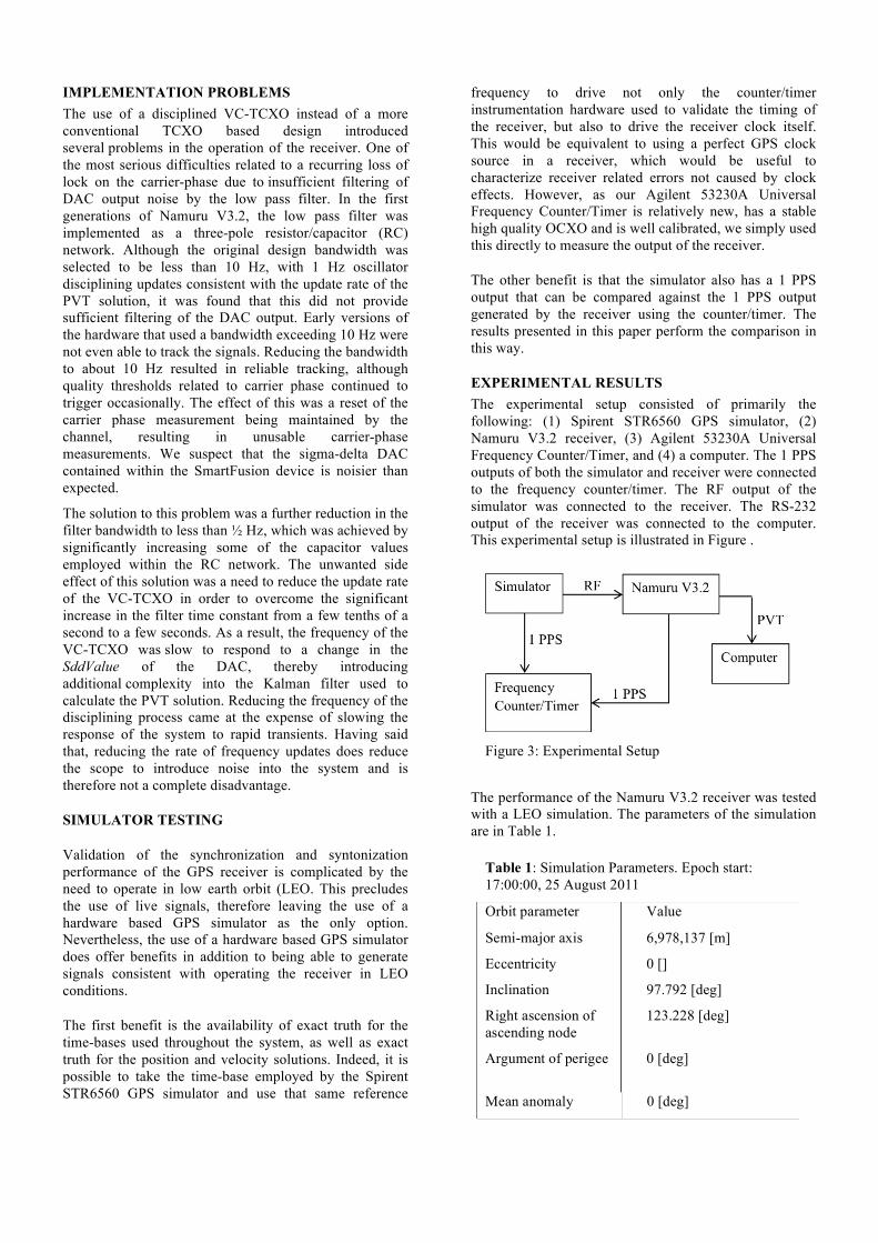
The time interval error between the simulator’s and receiver’s 1 PPS signals was measured with the frequency counter/timer for both sawtooth and sawtoothless settings. Since the 1 PPS of the simulator was assumed to be perfect, the time interval error was assumed to be entirely due to the receiver. Although this is not entirely true, it is a necessary and proper assumption since only one frequency counter/timer was available and the 1 PPS output by the simulator is of much higher quality than that output by the receiver (and most other receivers, for that matter). Two different sets of flags are used to configure the receiver’s timing mode: (1) ‘V/v’ and (2) ‘S/s’. The ‘V/v’ set refers to frequency disciplining, where ‘V’ and ‘v’ correspond to no disciplining and disciplining, respectively. The ‘S/s’ set refers to sawtooth, where ‘S’ and ‘s’ correspond to sawtooth and no sawtooth, respectively. Thus, there are three possible timing modes: (1) ‘V’ and ‘S’, (2) ‘v’ and ‘S’, (3) ‘v’ and ‘s’. The first mode (no frequency disciplining, with sawtooth) is perhaps the most familiar to the reader since no VC-TCXO is required. The second mode (with frequency disciplining, no sawtooth), on the other hand, requires the use of a voltage-controlled oscillator (like a VC-TCXO).
In this mode, the number of clock cycles the 1 PPS is triggered on is set equal to a constant, integer number. The third mode (with frequency disciplining, with sawtooth) also requires the use of a voltage-controlled oscillator, but is slightly different from the second mode since sawtooth is allowed. As of this writing, the third mode has not been tested. The time interval errors for the sawtooth case (first mode) are shown in Figures 4 and 5.
The sawtooth is readily apparent in Figure 4 and has an error moderating effect in the sense that its immediate effect is to reduce the time interval error, which has grown large enough such that triggering the 1 PPS of the receiver on a different number of integer cycles results in a more accurate 1 PPS. Thus, although the sawtooth is unsightly, its immediate effect is beneficial, provided the user does not require a smooth 1 PPS series. Since the clock frequency is 40 MHz, the sawtooth band should theoretically be 25 ns wide. The 40 MHz clock frequency is derived from the 10 MHz VC-TCXO frequency after multiplication by 4 within the GP2015 RF front end.
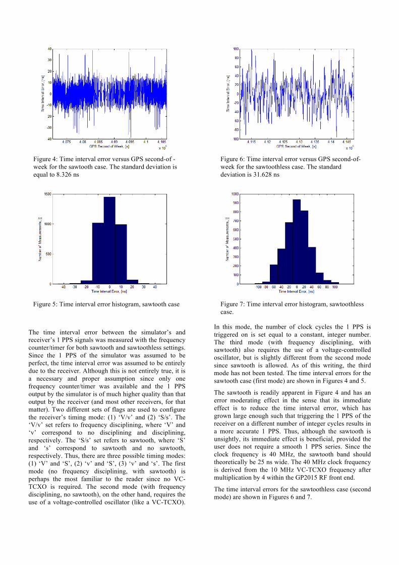
The time interval errors for the sawtoothless case (second mode) are shown in Figures 6 and 7.
Figure 4: Time interval error versus GPS second-of -week for the sawtooth case. The standard deviation is equal to 8.326 ns
Figure 5: Time interval error histogram, sawtooth case
Figure 6: Time interval error versus GPS second-of-week for the sawtoothless case. The standard deviation is 31.628 ns
Figure 7: Time interval error histogram, sawtoothless case.
In Figures 6 and 7, the sawtooths have been eliminated; however, the absence of their error moderating effect has resulted in occasionally larger time interval errors. Admittedly, the sawtoothless setting results in worse performance than the sawtooth setting. Without the aforementioned error moderating effect, the trigger time of the receiver 1 PPS output is changed solely by disciplining the VC-TCXO. As a result, when the frequency of the VC-TCXO (inevitably) drifts from its nominal value (in this case, 10 MHz), an excursion from the nominal 1 PPS occurs. To counter this effect, the voltage supplied to the VC-TCXO is adjusted, which changes its frequency. In some cases, this works rather well (e.g., where the time interval error is bounded to within ±12.5 ns). In other cases, the frequency of the VC-TCXO is not changed quickly enough and larger time interval errors (e.g., >±50 ns) develop. But, what then is the purpose of using a VC-TCXO to achieve a sawtoothless 1 PPS series if the results are worse? Aside from being an interesting problem to solve (that of achieving both synchronization and syntonization simultaneously), the use of a VC-TCXO can achieve better results than a conventional TCXO (although this not readily apparent from the results). There are a few catches: (1) the VC-TCXO must be of high enough quality such that a control algorithm exists to achieve improved performance and (2) the estimates of the clock bias and clock drift must accurately reflect the actual clock bias and clock drift. There is always the possibility that no control algorithm is capable of achieving superior performance in sawtoothless mode. This would likely be the case if the short-term stability of the VC-TCXO was particularly lacking, or in environmentally challenging environments where large and fast-moving temperature fluctuations result in frequency fluctuations that are difficult to counter, or if the estimates of the clock bias and clock drift are not particularly accurate (e.g., the latter to within a few parts per billion over the short-term).
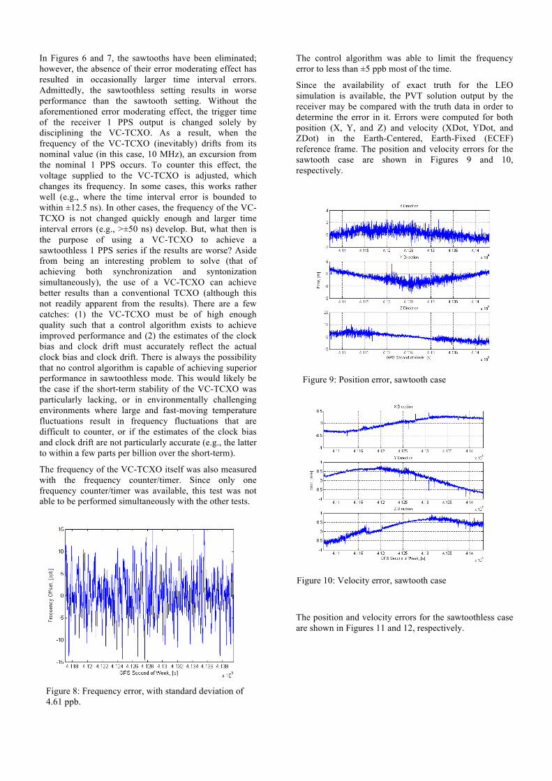
The frequency of the VC-TCXO itself was also measured with the frequency counter/timer. Since only one frequency counter/timer was available, this test was not able to be performed simultaneously with the other tests.
The control algorithm was able to limit the frequency error to less than ±5 ppb most of the time.
Since the availability of exact truth for the LEO simulation is available, the PVT solution output by the receiver may be compared with the truth data in order to determine the error in it. Errors were computed for both position (X, Y, and Z) and velocity (XDot, YDot, and ZDot) in the Earth-Centered, Earth-Fixed (ECEF) reference frame. The position and velocity errors for the sawtooth case are shown in Figures 9 and 10, respectively.
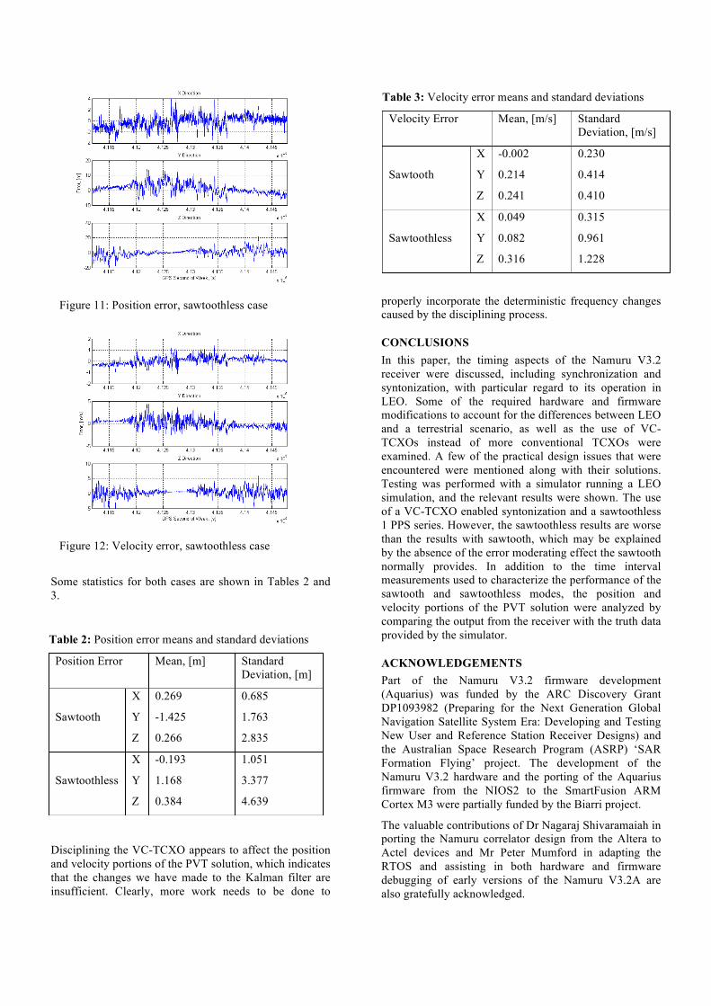
The position and velocity errors for the sawtoothless case are shown in Figures 11 and 12, respectively.
Figure 8: Frequency error, with standard deviation of 4.61 ppb.
Figure 9: Position error, sawtooth case
Figure 10: Velocity error, sawtooth case
Some statistics for both cases are shown in Tables 2 and 3.
Disciplining the VC-TCXO appears to affect the position and velocity portions of the PVT solution, which indicates that the changes we have made to the Kalman filter are insufficient. Clearly, more work needs to be done to
properly incorporate the deterministic frequency changes caused by the disciplining process.
CONCLUSIONS In this paper, the timing aspects of the Namuru V3.2 receiver were discussed, including synchronization and syntonization, with particular regard to its operation in LEO. Some of the required hardware and firmware modifications to account for the differences between LEO and a terrestrial scenario, as well as the use of VC-TCXOs instead of more conventional TCXOs were examined. A few of the practical design issues that were encountered were mentioned along with their solutions. Testing was performed with a simulator running a LEO simulation, and the relevant results were shown. The use of a VC-TCXO enabled syntonization and a sawtoothless 1 PPS series. However, the sawtoothless results are worse than the results with sawtooth, which may be explained by the absence of the error moderating effect the sawtooth normally provides. In addition to the time interval measurements used to characterize the performance of the sawtooth and sawtoothless modes, the position and velocity portions of the PVT solution were analyzed by comparing the output from the receiver with the truth data provided by the simulator.
ACKNOWLEDGEMENTS Part of the Namuru V3.2 firmware development (Aquarius) was funded by the ARC Discovery Grant DP1093982 (Preparing for the Next Generation Global Navigation Satellite System Era: Developing and Testing New User and Reference Station Receiver Designs) and the Australian Space Research Program (ASRP) ‘SAR Formation Flying’ project. The development of the Namuru V3.2 hardware and the porting of the Aquarius firmware from the NIOS2 to the SmartFusion ARM Cortex M3 were partially funded by the Biarri project.
The valuable contributions of Dr Nagaraj Shivaramaiah in porting the Namuru correlator design from the Altera to Actel devices and Mr Peter Mumford in adapting the RTOS and assisting in both hardware and firmware debugging of early versions of the Namuru V3.2A are also gratefully acknowledged.
1
Table 2: Position error means and standard deviations
Position Error Mean, [m] Standard Deviation, [m]
Sawtooth
X 0.269 0.685
Y -1.425 1.763
Z 0.266 2.835
Sawtoothless
X -0.193 1.051
Y 1.168 3.377
Z 0.384 4.639
2
Table 3: Velocity error means and standard deviations
Velocity Error Mean, [m/s] Standard Deviation, [m/s]
Sawtooth
X -0.002 0.230
Y 0.214 0.414
Z 0.241 0.410
Sawtoothless
X 0.049 0.315
Y 0.082 0.961
Z 0.316 1.228
Figure 11: Position error, sawtoothless case
Figure 12: Velocity error, sawtoothless case
REFERENCES [1] O. Montenbruck, M. Markgraf, M. Garcia-Fenandez,
and A. Helm, "GPS for Microsatellites - Status and Perspectives," in 6th IAA Symposium on Small Satellites for Earth Observation, Berlin, 2007.
[2] H. Heidt, J. Puig-Suari, A. S. Moore, S. Nakasuka, and R. J. Twiggs, "CubeSat: A new generation of picosatellite for education and industry low-cost space experimentation," in Proceedings of the 14th Annual AIAA/USU Conference on Small Satellites, 2000, pp. 1-19.
[3] CubeSatShop, Accessed: 18 January 2013 URL: http://www.cubesatshop.com [4] CubeSat Suppliers, Accessed: 18 January 2013 URL:
http://www.cubesat.org/index.php/collaborate/suppliers
[5] QB50, an FP7 project, Accessed: 18 January 2013 URL: http://www.qb50.eu
[6] G. Newsam and N. Gordon, "An Update on SSA in Australia," in Advanced Maui Optical and Space Surveillance Technologies Conference, 2011, p. 57.
[7] Nanosat Engineering Boeing, "Colony 2 Bus Payload Developer Guide: Version 1.2," ed. Huntington Beach, CA: Boeing Phantom Works, 2011.
[8] E. Kahr, "In-Orbit Performance of the CanX-2 Nanosatellite’s GPS Receiver," Master of Science Thesis, Department of Geomatics Engineering, University of Calgary, 2011.
[9] General Dynamics Corporation, Accessed: 27 January 2013 URL: http://www.dynamics.co.nz
[10] É. Glennon, K. Parkinson, P. Mumford, N. Shivaramaiah, Y. Li, R. Li, et al., "A GPS Receiver Designed for Cubesat Operations," in Australian Space Science Conference, 2011, pp. 26-29.
[11] A. J. Van Dierendonck, J. McGraw, and R. G. Brown, "Relationship between Allan variances and Kalman filter parameters," DTIC Document1984.