Embed Size (px)
Citation preview
Operator’s Manual
Hybrid Multi-Mode Microplate Reader
Synergy™ H1


Synergy H1™
Hybrid Multi-Mode Microplate Reader Operator’s Manual
June 2012 © 2012 Part Number 8041000 Revision D BioTek® Instruments, Inc.
ii | Notices
Notices
BioTek® Instruments, Inc.
Highland Park, P.O. Box 998
Winooski, Vermont 05404-0998 USA
All Rights Reserved
© 2012, BioTek® Instruments, Incorporated. No part of this publication may be reproduced, transcribed, or transmitted in any form, or by any means electronic or mechanical, including photocopying and recording, for any purpose other than the purchaser’s use without written permission of BioTek Instruments, Inc.
Trademarks
BioTek® is a registered trademark, and Synergy™ H1, Gen5™, BioStack™, and Take3™ and Take3Trio™ Micro-Volume Plates are trademarks of BioTek Instruments, Inc. Harta™ is a trademark of Harta Instruments. Glowell™ is a trademark of LUX Biotechnology, Ltd.
Microsoft®, Windows®, and Excel® are either registered trademarks or trademarks of Microsoft Corporation in the United States and/or other countries.
Kalrez® is a registered trademark of DuPont Performance Elastomers, L.L.C. (DPE).
All other trademarks are the property of their respective holders.
Restrictions and Liabilities
Information in this document is subject to change and does not represent a commitment by BioTek Instruments, Inc. Changes made to the information in this document will be incorporated in new editions of the publication. No responsibility is assumed by BioTek for the use or reliability of software or equipment that is not supplied by BioTek or its affiliated dealers.
BioTek Instruments, Inc.
Contents | iii
Contents
Contact Information ......................................................................... v Revision History .............................................................................. vi Document Conventions ................................................................... vii Intended Use Statement ................................................................. vii Quality Control ............................................................................. viii Warranty and Product Registration .................................................. viii Repackaging and Shipping .............................................................. viii Warnings ..................................................................................... viii Hazards ......................................................................................... ix Precautions ..................................................................................... x CE Mark ......................................................................................... xi Electromagnetic Interference and Susceptibility .................................. xii User Safety .................................................................................. xiii Safety Symbols ............................................................................. xiv
Introduction ........................................................................................ 1 Product Description ......................................................................... 2 Package Contents & Accessories ........................................................ 3 Optional Accessories ........................................................................ 4 Product Support & Service ................................................................ 6
Installation ......................................................................................... 7 Product Registration ........................................................................ 8 Important Information ..................................................................... 8 1: Unpack and Inspect the Reader ..................................................... 9 2: Unpack and Inspect the Dispense Module ....................................... 9 3: Unpack and Inspect the Gas Controller .......................................... 10 4: Select an Appropriate Location ..................................................... 11 5: Remove the Shipping Hardware .................................................... 11 6: Install the Power Supply .............................................................. 12 7: Connect the Gas Controller .......................................................... 13 8: Install the Dispense Module ......................................................... 13 9: Connect the Host Computer ......................................................... 16 10: Install Gen5 on the Host Computer ............................................. 17 11: Turn on the Reader ................................................................... 17 12: Establish Communication ........................................................... 17 13: Run a System Test ................................................................... 18 14: Test the Injector System ........................................................... 19 Operational/Performance Qualification ............................................... 21 Repackaging and Shipping Instructions ............................................. 21
Getting Started .................................................................................. 29 Modular Design .............................................................................. 30 External Components ...................................................................... 31 Internal Components ...................................................................... 31
Synergy H1 Operator’s Manual
iv | Contents
BioTek Instruments, Inc.
Gen5 Software ............................................................................... 36 Recommendations for Optimum Performance ..................................... 39
Filters and Mirrors ............................................................................. 41 Filter Cube Overview ...................................................................... 42 Filters and Mirrors .......................................................................... 46
Preventive Maintenance .................................................................... 51 Preventive Maintenance .................................................................. 52 Warnings and Precautions ............................................................... 53 Clean Exposed Surfaces .................................................................. 54 Inspect/Clean Excitation and Emission Filters ..................................... 55 Inspect/Clean Mirrors ..................................................................... 56 Flush/Purge the Fluid Path ............................................................... 58 Run a Dispense Protocol (Optional) ................................................... 59 Empty/Clean the Tip Priming Trough ................................................. 60 Clean the Priming Plate ................................................................... 60 Clean the Dispense Tubes and Injectors ............................................ 61
As-Needed Maintenance .................................................................... 63 Decontamination ............................................................................ 64 Dispense Module: Syringe Replacement ............................................. 70
Instrument Qualification ................................................................... 73 Overview ...................................................................................... 75 IQ/OQ/PQ ..................................................................................... 75 Recommended Qualification Schedule ............................................... 76 System Test .................................................................................. 77 Absorbance Plate Test ..................................................................... 83 Absorbance Liquid Tests .................................................................. 89 Fluorescence Liquid Tests ................................................................ 97 Luminescence Test ....................................................................... 120 Dispense Module Tests .................................................................. 127
Specifications .................................................................................. 139 General Specifications ................................................................... 140 Absorbance Specifications ............................................................. 141 Dispense/Read Specifications ......................................................... 142 Fluorescence Specifications (Mono-Based) ....................................... 142 Fluorescence Specifications (Filter-Based) ........................................ 143 Luminescence Specifications .......................................................... 144
Error Codes ..................................................................................... 145 Overview .................................................................................... 146 Error Codes ................................................................................. 147
Instrument Dimensions for Robotic Interface ................................. 151
Contact Information | v
Contact Information
See also Product Support & Service on page 6.
BioTek® Instruments, Inc.
Highland Park, P.O. Box 998
Winooski, Vermont 05404-0998 USA
Customer Service and Sales
Internet: www.biotek.com
Phone: 888-451-5171 (toll free in the U.S.) 802-655-4740 (outside the U.S.)
Fax: 802-655-7941
E-Mail: [email protected]
Service/TAC
Phone: 800-242-4685 (toll free in the U.S.) 802-655-4740 (outside the U.S.)
Fax: 802-654-0638
E-Mail: [email protected]
European Coordination Center/ Authorized European Representative
BioTek® Instruments GmbH Kocherwaldstrasse 34 D-74177 Bad Friedrichshall Germany
Internet: www.biotek.de
Phone: +49 (0) 7136 9680
Fax: +49 (0) 7136 968 111
E-Mail: [email protected]
Synergy H1 Operator’s Manual
vi | Revision History
Revision History
Rev Date Changes
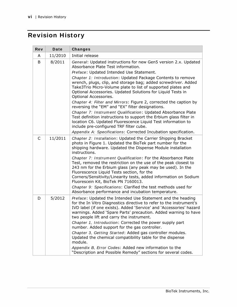
A 11/2010 Initial release
B 8/2011 General: Updated instructions for new Gen5 version 2.x. Updated Absorbance Plate Test information. Preface: Updated Intended Use Statement. Chapter 1: Introduction: Updated Package Contents to remove wrench, plugs, clip, and storage bag; added screwdriver. Added Take3Trio Micro-Volume plate to list of supported plates and Optional Accessories. Updated Solutions for Liquid Tests in Optional Accessories. Chapter 4: Filter and Mirrors: Figure 2, corrected the caption by reversing the “EM” and “EX” filter designations. Chapter 7: Instrument Qualification: Updated Absorbance Plate Test definition instructions to support the Erbium glass filter in location C6. Updated Fluorescence Liquid Test information to include pre-configured TRF filter cube. Appendix A: Specifications: Corrected Incubation specification.
C 11/2011 Chapter 2: Installation: Updated the Carrier Shipping Bracket photo in Figure 1. Updated the BioTek part number for the shipping hardware. Updated the Dispense Module installation instructions. Chapter 7: Instrument Qualification: For the Absorbance Plate Test, removed the restriction on the use of the peak closest to 243 nm for the Erbium glass (any peak may be used). In the Fluorescence Liquid Tests section, for the Corners/Sensitivity/Linearity tests, added information on Sodium Fluorescein Kit, BioTek PN 7160013. Chapter 9: Specifications: Clarified the test methods used for Absorbance performance and incubation temperature.
D 5/2012 Preface: Updated the Intended Use Statement and the heading for the In Vitro Diagnostics directive to refer to the instrument’s IVD label (if one exists). Added ‘Service’ and ‘Accessories’ hazard warnings. Added ‘Spare Parts’ precaution. Added warning to have two people lift and carry the instrument. Chapter 1, Introduction: Corrected the power supply part number. Added support for the gas controller. Chapter 3, Getting Started: Added gas controller modules. Updated the chemical compatibility table for the dispense module. Appendix B, Error Codes: Added new information to the “Description and Possible Remedy” sections for several codes.
BioTek Instruments, Inc.
Document Conventions | vii
Document Conventions
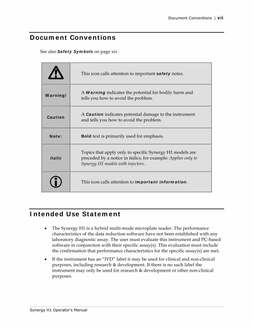
See also Safety Symbols on page xiv.
This icon calls attention to important safety notes.
Warning! A Warning indicates the potential for bodily harm and tells you how to avoid the problem.
Caution A Caution indicates potential damage to the instrument and tells you how to avoid the problem.
Note: Bold text is primarily used for emphasis.
italic Topics that apply only to specific Synergy H1 models are preceded by a notice in italics, for example: Applies only to Synergy H1 models with injectors.
This icon calls attention to important information.
Intended Use Statement
• The Synergy H1 is a hybrid multi-mode microplate reader. The performance characteristics of the data reduction software have not been established with any laboratory diagnostic assay. The user must evaluate this instrument and PC-based software in conjunction with their specific assay(s). This evaluation must include the confirmation that performance characteristics for the specific assay(s) are met.
• If the instrument has an “IVD” label it may be used for clinical and non-clinical purposes, including research & development. If there is no such label the instrument may only be used for research & development or other non-clinical purposes.
Synergy H1 Operator’s Manual
viii | Quality Control
Quality Control
It is considered good laboratory practice to run laboratory samples according to instruc-tions and specific recommendations included in the assay package insert for the test to be conducted. Failure to conduct Quality Control checks could result in erroneous test data.
Warranty and Product Registration
Take a moment to review the warranty information that shipped with your product. Please also register your product with BioTek to ensure that you receive important information and updates about the product(s) you have purchased. You can register online through the Customer Resource Center (CRC) at www.biotek.com or by calling 888-451-5171 or 802-655-4740.
Repackaging and Shipping
If you need to ship the instrument to BioTek for service or repair, contact BioTek for a Return Materials Authorization (RMA) number, and be sure to use the original packing materials. Other forms of commercially available packaging are not recommended and can void the warranty. If the original packing materials have been damaged or lost, contact BioTek for replacement packing.
Warnings
Operate the instrument on a level, stable surface away from excessive humidity.
Bright light or strong incandescent light can reduce the linear performance range of the instrument.
Measurement values may be affected by extraneous particles (such as dust) in the microplate wells. A clean work area is necessary to ensure accurate readings.
When operated in a safe environment according to the instructions in this document, there are no known hazards associated with the instrument. However, the operator should be aware of certain situations that could result in serious injury; these may vary depending on the instrument type. See Hazards and Precautions.
BioTek Instruments, Inc.
Hazards | ix
Hazards
The following hazard warnings are provided to help avoid injury:
Warning! Internal Voltage. Always turn off the power switch and unplug the power supply before cleaning the outer surface of the instrument or removing its top case.
Warning! Power Rating. The instrument’s power supply or power cord must be connected to a power receptacle that provides voltage and current within the specified rating for the system. Use of an incompatible power receptacle may produce electrical shock and fire hazards.
Warning! Electrical Grounding. Never use a plug adapter to connect primary power to the external power supply. Use of an adapter disconnects the utility ground, creating a severe shock hazard. Always connect the power cord directly to an appropriate receptacle with a functional ground.
Warning! Service. Only qualified technical personnel should perform service procedures on internal components.
Warning! Accessories. Only accessories that meet the manufacturer’s specifications shall be used with the instrument.
Warning! The instrument with all available modules weighs up to 55 pounds (24.95 kg). Use two people when lifting and carrying the instrument.
Warning! Liquids. Avoid spilling liquids on the instrument; fluid seepage into internal components creates a potential for shock hazard or instrument damage. If a spill occurs while a program is running, abort the program and turn the instrument off. Wipe up all spills immediately. Do not operate the instrument if internal components have been exposed to fluid. Contact BioTek TAC for assistance.
Warning! Unspecified Use. Failure to operate the equipment according to the guidelines and safeguards specified in this manual could result in a hazardous condition.
Warning! Software Quality Control. The operator must follow the manufacturer’s assay package insert when modifying software parameters and establishing reading methods. Failure to conduct quality control checks could result in erroneous test data.
Warning! Reader Data Reduction Protocol. No limits are applied to the raw measurement data. All information exported via computer control must be thoroughly analyzed by the operator.
Synergy H1 Operator’s Manual
x | Precautions
Warning! Potential Biohazards. Some assays or specimens may pose a biohazard. This hazard is noted by the symbol shown here. Adequate safety precautions should be taken as outlined in the assay’s package insert. Always wear safety glasses and appropriate protective equipment, such as chemical-resistant rubber gloves and apron.
Precautions
The following precautions are provided to help avoid damage to the instrument:
Caution: Service. The instrument should be serviced by BioTek-authorized personnel. Only qualified technical personnel should perform troubleshooting and service procedures on internal components.
Caution: Spare Parts. Only approved spare parts should be used for maintenance. The use of unapproved spare parts and accessories may result in a loss of warranty and potentially impair instrument performance or cause damage to the instrument.
Caution: Environmental Conditions. Do not expose the system to temperature extremes. For proper operation, ambient temperatures should remain within the range listed in the Specifications section. Performance may be adversely affected if temperatures fluctuate above or below this range. Storage temperature limits are broader.
Caution: Sodium Hypochlorite. Do not expose any part of the instrument to the recommended diluted sodium hypochlorite solution (bleach) for more than 20 minutes. Prolonged contact may damage the instrument surfaces. Be certain to rinse and thoroughly wipe all surfaces.
Caution: Power Supply. Use only the power supply shipped with the instrument within the range of line voltages listed on it.
Caution: Disposal. This instrument contains printed circuit boards and wiring with lead solder. Dispose of the instrument according to Directive 2002/96/EC, “on waste electrical and electronic equipment (WEEE)” or local ordinances.
Caution: Warranty. Failure to follow preventive maintenance procedures may void the warranty.
Caution: Shipping Hardware. All shipping hardware (e.g., carrier shipping screw, filter reader shipping bracket) must be removed before operating the instrument and reinstalled before repackaging the instrument for shipment.
Caution: Electromagnetic Environment. Per EN 61326-2-6 it is the user’s responsibility to ensure that a compatible electromagnetic environment for this instrument is provided and maintained in order that the device will perform as intended.
BioTek Instruments, Inc.
CE Mark | xi
Caution: Electromagnetic Compatibility. Do not use this device in close proximity to sources of strong electromagnetic radiation (e.g., unshielded intentional RF sources), because these may interfere with the proper operation.
CE Mark
Based on the testing described below and information contained herein, this instrument bears the CE mark.
See the Declaration of Conformity for more specific information.
Directive 2004/108/EC: Electromagnetic Compatibility
Emissions—CLASS A
The system has been type-tested by an independent, accredited testing laboratory and found to meet the requirements of EN 61326-1: Class A for Radiated Emissions and Line Conducted Emissions.
Verification of compliance was conducted to the limits and methods of EN 55011–(CISPR 11) Class A. In a domestic environment it may cause radio interference, in which case you may need to mitigate the interference.
Immunity
The system has been type-tested by an independent, accredited testing laboratory and found to meet the requirements of EN 61326-1 and EN 61326-2-6 for Immunity. Verification of compliance was conducted to the limits and methods of the following:
EN 61000-4-2, Electrostatic Discharge EN 61000-4-3, Radiated EM Fields EN 61000-4-4, Electrical Fast Transient/Burst EN 61000-4-5, Surge Immunity EN 61000-4-6, Conducted Disturbances from RFI EN 61000-4-11, Voltage Dips, Short Interruptions and Variations
Directive 2006/95/EC Low Voltage (Safety)
The system has been type-tested by an independent testing laboratory and was found to meet the requirements of this Directive. Verification of compliance was conducted to the limits and methods of the following:
EN 61010-1, “Safety requirement for electrical equipment for measurement, control and laboratory use. Part 1, General requirements.”
Synergy H1 Operator’s Manual
xii | Electromagnetic Interference and Susceptibility
EN 61010-2-081, “Requirements for automatic and semi-automatic laboratory equipment for analysis and other purposes.”
Directive 2002/96/EC: Waste Electrical and Electronic Equipment
Disposal Notice: This instrument contains printed circuit boards and wiring with lead solder. Dispose of the instrument according to Directive 2002/96/EC, “on waste electrical and electronic equipment (WEEE)” or local ordinances.
Directive 98/79/EC: In Vitro Diagnostics (if labeled for this use)
• Product registration with competent authorities
• Traceability to the U.S. National Institute of Standards and Technology (NIST).
• EN 61010-2-101, “Particular requirements for in vitro diagnostic (IVD) medical equipment.”
Electromagnetic Interference and Susceptibility
USA FCC CLASS A
RADIO AND TELEVISION INTERFERENCE
NOTE: This equipment has been tested and found to comply with the limits for a Class A digital device, pursuant to Part 15 of the FCC Rules. These limits are designed to provide reasonable protection against harmful interference when the equipment is operated in a commercial environment. This equipment generates, uses, and can radiate radio frequency energy and, if not installed and used in accordance with the instruction manual, may cause harmful interference to radio communications. Operation of this equipment in a residential area is likely to cause harmful interference, in which case the user will be required to correct the interference at their own expense.
In order to maintain compliance with FCC regulations shielded cables must be used with this equipment. Operation with non-approved equipment or unshielded cables is likely to result in interference to radio and television reception.
Canadian Department of Communications Class A
This digital apparatus does not exceed Class A limits for radio emissions from digital apparatus set out in the Radio Interference Regulations of the Canadian Department of Communications.
Le present appareil numerique n'émet pas de bruits radioelectriques depassant les limites applicables aux appareils numerique de la Class A prescrites dans le Reglement sur le brouillage radioelectrique edicte par le ministere des Communications du Canada.
BioTek Instruments, Inc.
User Safety | xiii
User Safety
This device has been type-tested by an independent laboratory and found to meet the requirements of the following:
• Underwriters Laboratories UL 61010-1, “Safety requirements for electrical equipment for measurement, control and laboratory use; Part 1: general requirements.”
• Canadian Standards Association CAN/CSA C22.2 No. 61010-1, “Safety requirements for electrical equipment for measurement, control and laboratory use; Part 1: general requirements.”
• EN 61010 standards, see CE Mark starting on page xi.
Synergy H1 Operator’s Manual

xiv | Safety Symbols
Safety Symbols
Some of these symbols may appear on the instrument or accessories:
Alternating current
Courant alternatif
Wechselstrom
Corriente alterna
Corrente alternata
Both direct and alternating current
Courant continu et courant alternatif
Gleich - und Wechselstrom
Corriente continua y corriente alterna
Corrente continua e corrente alternata
Direct current
Courant continu
Gleichstrom
Corriente continua
Corrente continua
Earth ground terminal
Borne de terre
Erde (Betriebserde)
Borne de tierra
Terra (di funzionamento)
On (Supply)
Marche (alimentation)
Ein (Verbindung mit dem Netz)
Conectado
Chiuso
Protective conductor terminal
Borne de terre de protection
Schutzleiteranschluss
Borne de tierra de protección
Terra di protezione
Off (Supply)
Arrêt (alimentation)
Aus (Trennung vom Netz)
Desconectado
Aperto (sconnessione dalla rete di alimentazione)
Caution (refer to accompanying documents)
Attention (voir documents d’accompanement)
Achtung siehe Begleitpapiere
Atención (vease los documentos incluidos)
Attenzione, consultare la doc annessa
Warning, risk of electric shock
Attention, risque de choc électrique
Gefährliche elektrische schlag
Precaución, riesgo de sacudida eléctrica
Attenzione, rischio di scossa elettrica
Warning, risk of crushing or pinching
Attention, risque d’écrasement et pincement
Warnen, Gefahr des Zerquetschens und Klemmen
Precaución, riesgo del machacamiento y sejeción
Attenzione, rischio di schiacciare ed intrappolarsi
Warning, hot surface
Attention, surface chaude
Warnen, heiße Oberfläche
Precaución, superficie caliente
Attenzione, superficie calda
Warning, potential biohazards
Attention, risques biologiques potentiels
Warnung! Moegliche biologische Giftstoffe
Atención, riesgos biológicos
Attenzione, rischio biologico
BioTek Instruments, Inc.
Safety Symbols | xv
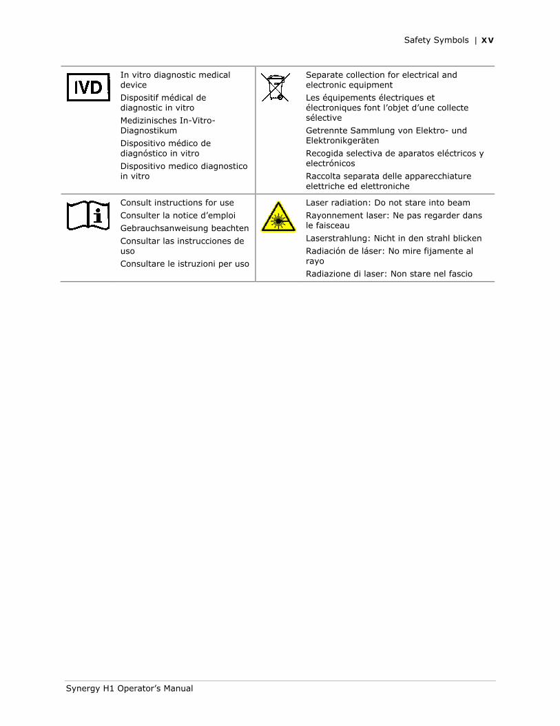
In vitro diagnostic medical device
Dispositif médical de diagnostic in vitro
Medizinisches In-Vitro-Diagnostikum
Dispositivo médico de diagnóstico in vitro
Dispositivo medico diagnostico in vitro
Separate collection for electrical and electronic equipment
Les équipements électriques et électroniques font l’objet d’une collecte sélective
Getrennte Sammlung von Elektro- und Elektronikgeräten
Recogida selectiva de aparatos eléctricos y electrónicos
Raccolta separata delle apparecchiature elettriche ed elettroniche
Consult instructions for use
Consulter la notice d’emploi
Gebrauchsanweisung beachten
Consultar las instrucciones de uso
Consultare le istruzioni per uso
Laser radiation: Do not stare into beam
Rayonnement laser: Ne pas regarder dans le faisceau
Laserstrahlung: Nicht in den strahl blicken
Radiación de láser: No mire fijamente al rayo
Radiazione di laser: Non stare nel fascio
Synergy H1 Operator’s Manual

xvi | Safety Symbols
BioTek Instruments, Inc.
Chapter 1
Introduction
This chapter introduces the Synergy H1 Hybrid Multi-Mode Microplate Reader, describes its hardware and software features, and provides contact information for technical assistance.
Product Description ............................................................ 2 Package Contents & Accessories .......................................... 3 Optional Accessories .......................................................... 4 Product Support & Service .................................................. 6
Technical Assistance Center (TAC) ................................... 6 Applications Support ...................................................... 6
2 | Chapter 1: Introduction
Product Description
The Synergy H1 is a hybrid multi-mode microplate reader. Depending on the model, Synergy H1 detection modes include fluorescence intensity (FI), fluorescence polarization (FP), time-resolved fluorescence (TRF), luminescence, and UV-visible absorbance. The instrument is modular, and upgrade options are available; contact BioTek Customer Care for more information.
The reader is computer-controlled using Gen5 software for all operations, including data reduction and analysis. The Synergy H1 is robot accessible and compatible with the BioStack Microplate Stacker. Gen5 supports OLE automation to facilitate the Synergy H1’s integration into an automated system.
The Synergy H1 can perform reads using a filter cube or a monochromator. The filter-based system can perform fluorescence and luminescence reads. Filter fluorescence uses a xenon flash light source, along with interference filters and dichroic mirrors for wavelength specificity and a photomultiplier tube (PMT) detector. To run a fluorescence polarization protocol, the filter cube must contain polarizing filters. Luminescence is measured through an empty filter position in the filter cube; filters can be used if light filtering is necessary.
The monochromator-based system, which has both top and bottom probes, is used for absorbance, fluorescence, and luminescence. Absorbance measurements are made using the reader’s monochromator optics. The xenon lamp allows for both UV and visible light measurements. The monochromator provides wavelength selection from 230–999 nm in 1-nm increments. Available read methods are endpoint, area scan, spectral scanning, and pathlength correction. For luminescence reads, the Synergy H1 has a direct-to-PMT channel (no filtering, white light only). You can also use the monochromator optics for luminescence spectral scanning.
The Synergy H1 has a 4-Zone temperature control from 4°C over ambient to 45°C. Internal plate shaking, with both linear and orbital modes, is supported to ensure that reagents are properly mixed prior to reading.
The Synergy H1 supports the reading of 6-, 12-, 24-, 48-, 96-, and 384-well microplates with 128 x 86 mm geometry as well as the Take3 and Take3 Trio Micro-Volume Plate.
Use of microplates other than those listed here can result in positioning errors during program execution.
Models with injectors support dual-reagent dispensing to 6-, 12-, 24-, 48-, 96-, and 384-well microplates. An external dispense module pumps fluid from the supply bottles to the two injectors located inside the instrument.
Models that support the gas controller can control the CO2 or O2 concentrations in the reading chamber for CO2- or O2-sensitive assays.
See Appendix A for performance and technical specifications.
BioTek Instruments, Inc.
Package Contents & Accessories | 3
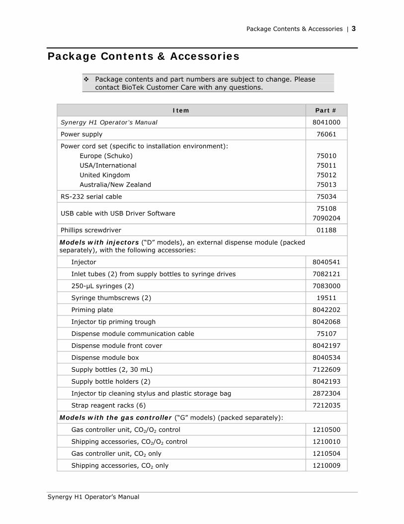
Package Contents & Accessories
Package contents and part numbers are subject to change. Please contact BioTek Customer Care with any questions.
Item Part #
Synergy H1 Operator’s Manual 8041000
Power supply 76061
Power cord set (specific to installation environment):
Europe (Schuko)
USA/International
United Kingdom
Australia/New Zealand
75010
75011
75012
75013
RS-232 serial cable 75034
USB cable with USB Driver Software 75108
7090204
Phillips screwdriver 01188
Models with injectors (“D” models), an external dispense module (packed separately), with the following accessories:
Injector 8040541
Inlet tubes (2) from supply bottles to syringe drives 7082121
250-µL syringes (2) 7083000
Syringe thumbscrews (2) 19511
Priming plate 8042202
Injector tip priming trough 8042068
Dispense module communication cable 75107
Dispense module front cover 8042197
Dispense module box 8040534
Supply bottles (2, 30 mL) 7122609
Supply bottle holders (2) 8042193
Injector tip cleaning stylus and plastic storage bag 2872304
Strap reagent racks (6) 7212035
Models with the gas controller (“G” models) (packed separately):
Gas controller unit, CO2/O2 control 1210500
Shipping accessories, CO2/O2 control 1210010
Gas controller unit, CO2 only 1210504
Shipping accessories, CO2 only 1210009
Synergy H1 Operator’s Manual
4 | Chapter 1: Introduction
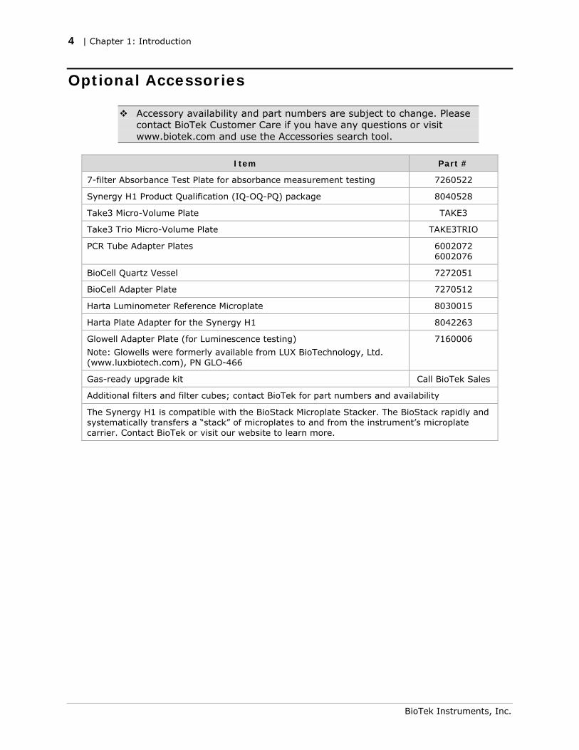
Optional Accessories
Accessory availability and part numbers are subject to change. Please contact BioTek Customer Care if you have any questions or visit www.biotek.com and use the Accessories search tool.
Item Part #
7-filter Absorbance Test Plate for absorbance measurement testing 7260522
Synergy H1 Product Qualification (IQ-OQ-PQ) package 8040528
Take3 Micro-Volume Plate TAKE3
Take3 Trio Micro-Volume Plate TAKE3TRIO
PCR Tube Adapter Plates 6002072 6002076
BioCell Quartz Vessel 7272051
BioCell Adapter Plate 7270512
Harta Luminometer Reference Microplate 8030015
Harta Plate Adapter for the Synergy H1 8042263
Glowell Adapter Plate (for Luminescence testing)
Note: Glowells were formerly available from LUX BioTechnology, Ltd. (www.luxbiotech.com), PN GLO-466
7160006
Gas-ready upgrade kit Call BioTek Sales
Additional filters and filter cubes; contact BioTek for part numbers and availability
The Synergy H1 is compatible with the BioStack Microplate Stacker. The BioStack rapidly and systematically transfers a “stack” of microplates to and from the instrument’s microplate carrier. Contact BioTek or visit our website to learn more.
BioTek Instruments, Inc.
Optional Accessories | 5
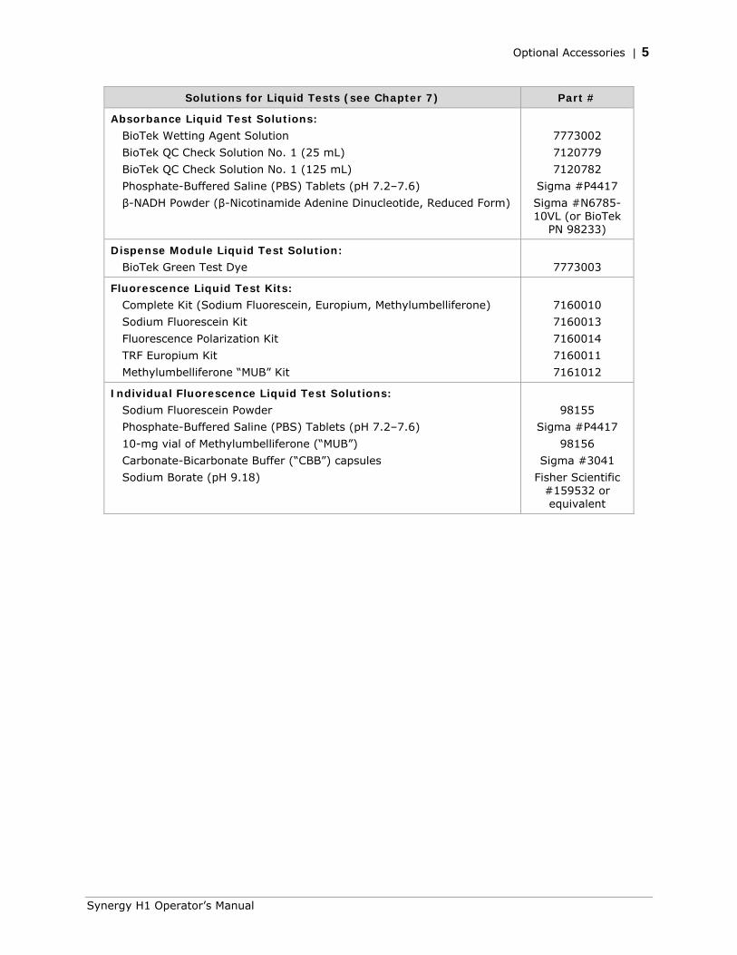
Solutions for Liquid Tests (see Chapter 7) Part #
Absorbance Liquid Test Solutions:
BioTek Wetting Agent Solution
BioTek QC Check Solution No. 1 (25 mL)
BioTek QC Check Solution No. 1 (125 mL)
Phosphate-Buffered Saline (PBS) Tablets (pH 7.2–7.6)
β-NADH Powder (β-Nicotinamide Adenine Dinucleotide, Reduced Form)
7773002
7120779
7120782
Sigma #P4417
Sigma #N6785-10VL (or BioTek
PN 98233)
Dispense Module Liquid Test Solution:
BioTek Green Test Dye
7773003
Fluorescence Liquid Test Kits:
Complete Kit (Sodium Fluorescein, Europium, Methylumbelliferone)
Sodium Fluorescein Kit
Fluorescence Polarization Kit
TRF Europium Kit
Methylumbelliferone “MUB” Kit
7160010
7160013
7160014
7160011
7161012
Individual Fluorescence Liquid Test Solutions:
Sodium Fluorescein Powder
Phosphate-Buffered Saline (PBS) Tablets (pH 7.2–7.6)
10-mg vial of Methylumbelliferone (“MUB”)
Carbonate-Bicarbonate Buffer (“CBB”) capsules
Sodium Borate (pH 9.18)
98155
Sigma #P4417
98156
Sigma #3041
Fisher Scientific #159532 or equivalent
Synergy H1 Operator’s Manual
6 | Chapter 1: Introduction
BioTek Instruments, Inc.
Product Support & Service
Technical Assistance Center (TAC)
If your instrument or software fails to function properly, if you have questions about how to use or maintain our products, or if you need to send an instrument to BioTek for service or repair, please contact our Technical Assistance Center (“TAC”).
TAC is open from 8:30 AM to 5:30 PM (EST), Monday through Friday, excluding standard U.S. holidays.
Phone: (800) 242-4685 or Fax: (802) 654-0638 E-Mail: [email protected] (802) 655-4740 Web: www.biotek.com
Please be prepared to provide the following information:
• Your name and company information, along with a daytime phone or fax number, and/or an e-mail address
• The product name, model, and serial number
• The onboard software part number and basecode version (available via Gen5 for the Synergy H1 by selecting System > Reader Control > Information)
• Gen5 software version information (Help > About Gen5)
• For troubleshooting assistance or instruments needing repair, the specific steps that produce your problem and any error codes displayed in Gen5 (see also Appendix B, Error Codes)
If you need to return an instrument to BioTek for service or repair, please contact the TAC for a Return Materials Authorization (RMA) number and the shipping address. Repackage the instrument according to the instructions at the end of Chapter 2, Installation.
Applications Support
BioTek’s fully equipped Application Laboratory provides our on-staff scientists with the means to assist you with the integration of our instrumentation and software with your unique scientific applications. If you are having difficulty with optimizing fluorescence sensitivity or integrating a unique data reduction transformation, or you are just looking for a recommendation on an appropriate fluorophore, contact us.
Phone: (888) 451-5171 E-Mail: [email protected]
Chapter 2
Installation
This chapter includes instructions for unpacking and setting up the Synergy H1 and, if applicable, the external dispense module. Instructions are also included for preparing the reader and dispense module for shipment.
Product Registration ........................................................... 8 Important Information ........................................................ 8 1: Unpack and Inspect the Reader ....................................... 9 2: Unpack and Inspect the Dispense Module .......................... 9 3: Unpack and Inspect the Gas Controller ........................... 10 4: Select an Appropriate Location ....................................... 11 5: Remove the Shipping Hardware ..................................... 11 6: Install the Power Supply ............................................... 12 7: Connect the Gas Controller ............................................ 13 8: Install the Dispense Module ........................................... 13 9: Connect the Host Computer .......................................... 16 10: Install Gen5 on the Host Computer ............................... 17 11: Turn on the Reader .................................................... 17 12: Establish Communication ............................................ 17 13: Run a System Test ..................................................... 18 14: Test the Injector System ............................................. 19 Operational/Performance Qualification ................................ 21 Repackaging and Shipping Instructions ............................... 21
Preparing the Dispense Module for Shipment ................... 25
8 | Chapter 2: Installation
Product Registration Please register your product(s) with BioTek to ensure that you receive important information and updates about the product(s) you have purchased.
Register online through BioTek’s Customer Resource Center (CRC) at www.biotek.com or by contacting BioTek Customer Care.
Important Information
This chapter contains installation and setup tasks for a Synergy H1 reader that has all of the available modules (the “H1MFDG” model). Your Synergy H1 model may be different. Perform the installation and setup tasks in the order presented, skipping those that do not apply to your reader’s configuration.
Materials: You will need a screwdriver to perform some of the steps in this section. You will also need a small wrench; this item is supplied with the instrument.
Remove the shipping hardware before turning on the instrument.
Re-install the shipping hardware before repackaging the instrument for shipment.
BioTek Instruments, Inc.
1: Unpack and Inspect the Reader | 9
1: Unpack and Inspect the Reader
The Synergy H1 with all available modules weighs up to 55 pounds (24.95 kg). Use two people when lifting and carrying the instrument.
Save all packaging materials. If you need to ship the reader to BioTek for repair or replacement, you must use the original materials. Using other forms of commercially available packaging, or failing to follow the repackaging instructions, may void the warranty. Improper packaging the results in damage to the reader may lead to additional charges.
During the unpacking process, inspect the packaging, reader, and accessories for shipping damage. If the reader is damaged, notify the carrier and your BioTek representative. Keep the shipping boxes and the packaging materials for the carrier’s inspection. BioTek will arrange for repair or replacement of your reader immediately.
1. Open the shipping box, remove the instrument from the box, and place it on a level, stable surface.
2. Place the packaging materials back into the shipping box for reuse if the instrument needs to be shipped again.
2: Unpack and Inspect the Dispense Module
Save all packaging materials. If you need to ship the dispense module to BioTek for repair or replacement, you must use the original materials. Using other forms of commercially available packaging, or failing to follow the repackaging instructions, may void your warranty.
During the unpacking process, inspect the packaging, module, and accessories for shipping damage. If the dispense module is damaged, notify the carrier and your BioTek representative. Keep the shipping boxes and the packaging materials for the carrier’s inspection. BioTek will arrange for repair or replacement of your dispense module immediately.
Synergy H1 Operator’s Manual
10 | Chapter 2: Installation
Each dispense module is calibrated to perform with its specific Synergy H1 reader. Make sure the same serial number appears on both the dispense module and the reader.
If applicable, perform these steps to unpack the dispense module. Refer to Figure 9 and Figure 10 on pages 26 and 27.
1. Open the shipping box. Remove the accessories box and foam insert that contains the injector tubing and bottle holders.
2. Lift out the module and place it on a level surface.
3. Open the accessories box and remove its contents. The accessories should include the dispense module–related items listed under Package Contents & Accessories in Chapter 1.
4. Place all packaging materials into the shipping box for reuse if the dispense module needs to be shipped.
3: Unpack and Inspect the Gas Controller
Save all packaging materials. If you need to ship the gas controller module to BioTek for repair or replacement, you must use the original materials. Using other forms of commercially available packaging, or failing to follow the repackaging instructions, may void your warranty.
During the unpacking process, inspect the packaging, module, and accessories for shipping damage. If the gas controller is damaged, notify the carrier and your BioTek representative. Keep the shipping boxes and the packaging materials for the carrier’s inspection. BioTek will arrange for repair or replacement of your gas controller module immediately.
If applicable, perform these steps to unpack the gas controller module.
1. Open the shipping box.
2. Lift out the accessories (power supply, tubing, and manual) and set them aside.
3. Lift out the module and place it on a level surface.
4. Place all packaging materials into the shipping box for reuse if the gas controller module needs to be shipped.
BioTek Instruments, Inc.
4: Select an Appropriate Location | 11
4: Select an Appropriate Location
Install the reader on a level, stable surface in an area where ambient temperatures between 18°C (64°F) and 40°C (104°F) can be maintained. Leave at least six inches of space between the instrument’s rear panel and any other object. This space ensures proper air flow in and out of the instrument.
The reader is sensitive to extreme environmental conditions. Avoid the following:
• Excessive humidity. Condensation directly on the sensitive electronic circuits can cause the instrument to fail internal self-checks. The humidity must be in the range of 10–85%, non-condensing.
• Excessive ambient light. Bright light may affect the reader’s optics and readings, reducing its linear range.
• Dust. Readings may be affected by extraneous particles (such as dust) in the microplate wells. A clean work area is necessary to ensure accurate readings.
If you are installing the BioStack for operation with the Synergy H1, be sure to allow enough room for both instruments and the host computer. The BioStack and the reader require a space approximately 42" D x 17" W x 24" H (for 30-plate stacks) or 34" H (for 50-plate stacks) (106.7 cm D x 43.2 cm W x 61 cm/86.5 cm H). You will also need additional room around the instruments for cables, power supplies, and the computer, and above the BioStack for stack removal.
You may wish to seat the instruments in their aligning plates now. Refer to the BioStack Operator’s Manual for more information.
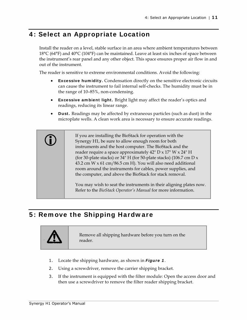
5: Remove the Shipping Hardware
Remove all shipping hardware before you turn on the reader.
1. Locate the shipping hardware, as shown in Figure 1.
2. Using a screwdriver, remove the carrier shipping bracket.
3. If the instrument is equipped with the filter module: Open the access door and then use a screwdriver to remove the filter reader shipping bracket.
Synergy H1 Operator’s Manual
12 | Chapter 2: Installation
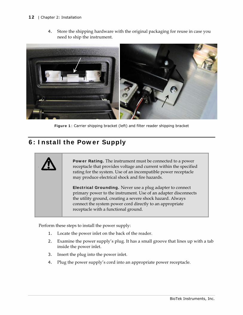
4. Store the shipping hardware with the original packaging for reuse in case you need to ship the instrument. 0.
Figure 1: Carrier shipping bracket (left) and filter reader shipping bracket
6: Install the Power Supply
Power Rating. The instrument must be connected to a power receptacle that provides voltage and current within the specified rating for the system. Use of an incompatible power receptacle may produce electrical shock and fire hazards.
Electrical Grounding. Never use a plug adapter to connect primary power to the instrument. Use of an adapter disconnects the utility ground, creating a severe shock hazard. Always connect the system power cord directly to an appropriate receptacle with a functional ground.
Perform these steps to install the power supply:
1. Locate the power inlet on the back of the reader.
2. Examine the power supply’s plug. It has a small groove that lines up with a tab inside the power inlet.
3. Insert the plug into the power inlet.
4. Plug the power supply’s cord into an appropriate power receptacle.
BioTek Instruments, Inc.
7: Connect the Gas Controller | 13
7: Connect the Gas Controller
See the Gas Controller User Guide for installation instructions.
8: Install the Dispense Module
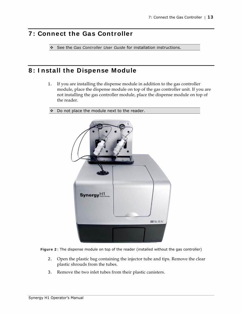
1. If you are installing the dispense module in addition to the gas controller module, place the dispense module on top of the gas controller unit. If you are not installing the gas controller module, place the dispense module on top of the reader.
Do not place the module next to the reader.
Figure 2: The dispense module on top of the reader (installed without the gas controller)
2. Open the plastic bag containing the injector tube and tips. Remove the clear plastic shrouds from the tubes.
3. Remove the two inlet tubes from their plastic canisters.
Synergy H1 Operator’s Manual
14 | Chapter 2: Installation
4. Identify the two syringe valves on the dispense module (see Figure 5). Each is labeled with a left-pointing arrow.
When installing the inlet and outlet tubes, do not use any tools. Finger-tighten only!
5. Screw the fitting of one inlet tube into the right side of the Syringe 1 valve.
6. Screw one end of one outlet tube into the left side of the Syringe 1 valve.
7. Repeat these steps to attach the inlet and outlet tubing for Syringe 2.
It is critical that the tubing is installed in the correct ports. Otherwise, injected fluid may miss the intended well.
8. Remove the tubing feed-through cover from the top of the reader (2 screws). Store the cover and screws with the shipping hardware in case the reader needs to be shipped again.
9. Thread the injector tip holder, with outlet tubing connected to both ports, through the hole in the top of the reader.
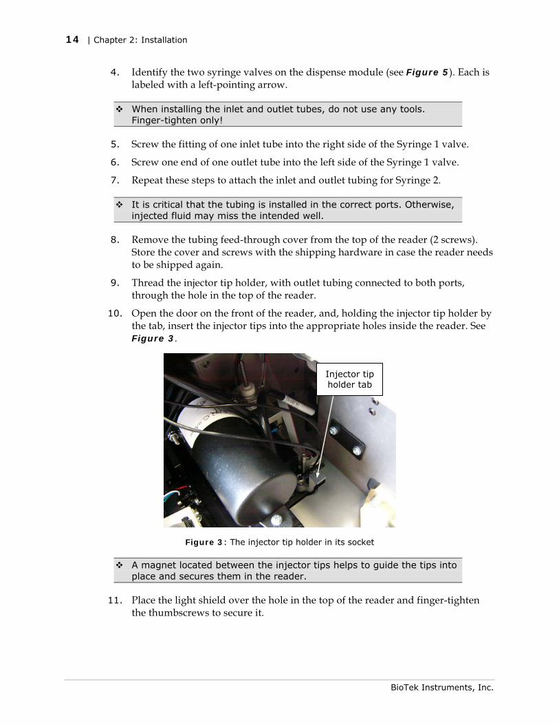
10. Open the door on the front of the reader, and, holding the injector tip holder by the tab, insert the injector tips into the appropriate holes inside the reader. See Figure 3.
Injector tip holder tab
Figure 3: The injector tip holder in its socket
A magnet located between the injector tips helps to guide the tips into place and secures them in the reader.
11. Place the light shield over the hole in the top of the reader and finger-tighten the thumbscrews to secure it.
BioTek Instruments, Inc.
8: Install the Dispense Module | 15
Synergy H1 Operator’s Manual
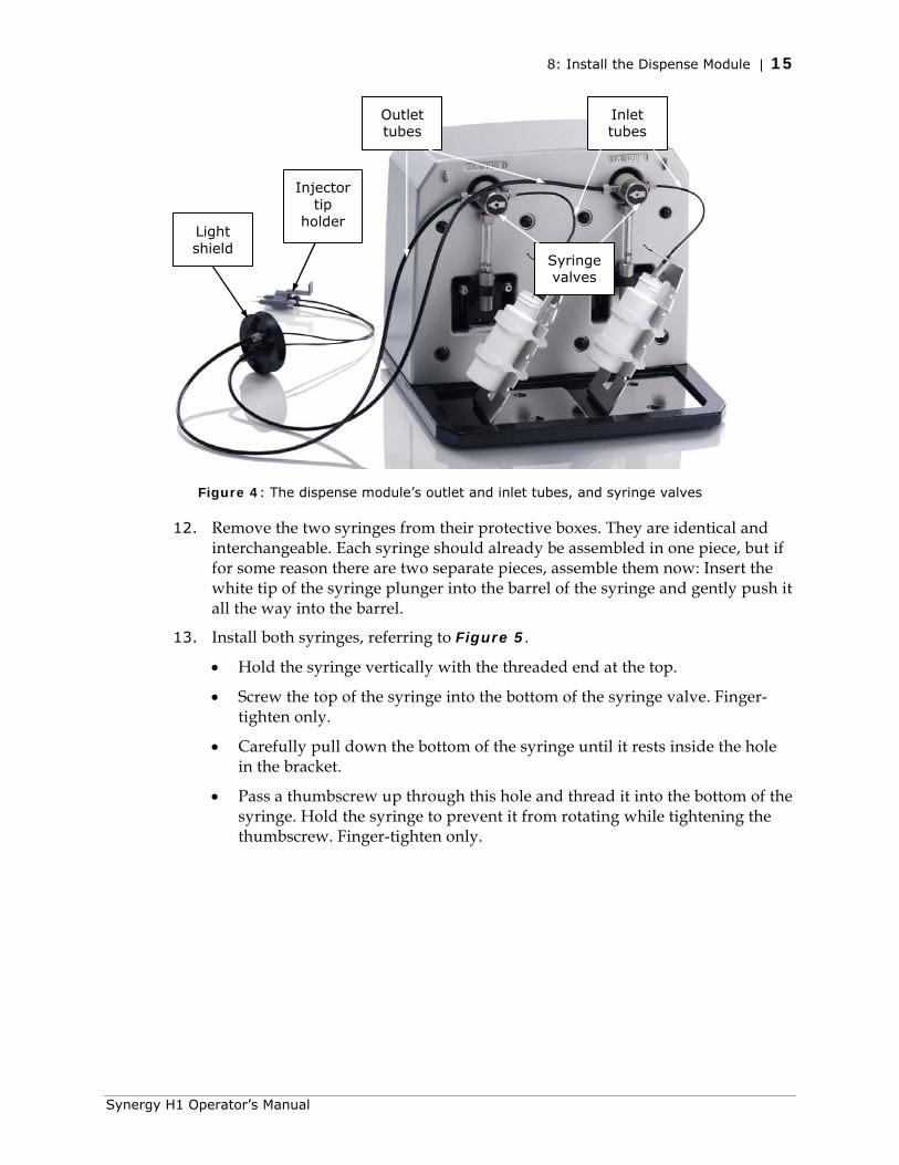
Figure 4: The dispense module’s outlet and inlet tubes, and syringe valves
12. Remove the two syringes from their protective boxes. They are identical and interchangeable. Each syringe should already be assembled in one piece, but if for some reason there are two separate pieces, assemble them now: Insert the white tip of the syringe plunger into the barrel of the syringe and gently push it all the way into the barrel.
13. Install both syringes, referring to Figure 5.
• Hold the syringe vertically with the threaded end at the top.
• Screw the top of the syringe into the bottom of the syringe valve. Finger-tighten only.
• Carefully pull down the bottom of the syringe until it rests inside the hole in the bracket.
• Pass a thumbscrew up through this hole and thread it into the bottom of the syringe. Hold the syringe to prevent it from rotating while tightening the thumbscrew. Finger-tighten only.
Outlet tubes
Inlet tubes
Syringe valves
Injector tip
holder Light shield
16 | Chapter 2: Installation
BioTek Instruments, Inc.
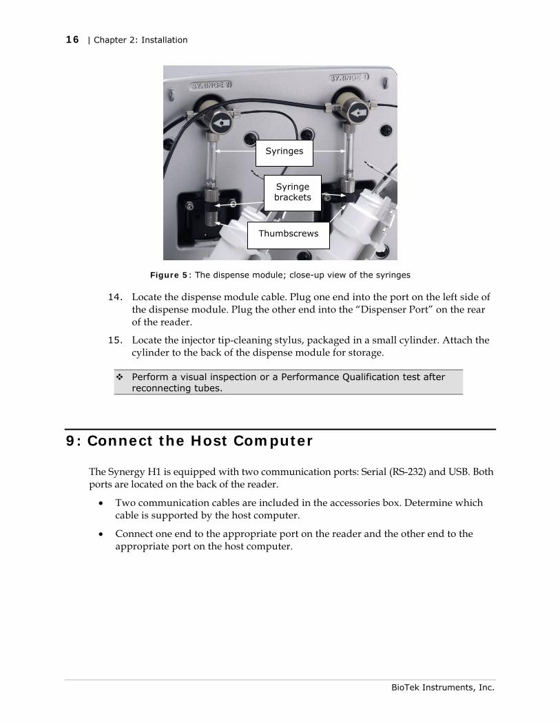
Figure 5: The dispense module; close-up view of the syringes
14. Locate the dispense module cable. Plug one end into the port on the left side of the dispense module. Plug the other end into the “Dispenser Port” on the rear of the reader.
15. Locate the injector tip-cleaning stylus, packaged in a small cylinder. Attach the cylinder to the back of the dispense module for storage.
Perform a visual inspection or a Performance Qualification test after reconnecting tubes.
9: Connect the Host Computer
The Synergy H1 is equipped with two communication ports: Serial (RS-232) and USB. Both ports are located on the back of the reader.
• Two communication cables are included in the accessories box. Determine which cable is supported by the host computer.
• Connect one end to the appropriate port on the reader and the other end to the appropriate port on the host computer.
Syringes
Syringe brackets
Thumbscrews

10: Install Gen5 on the Host Computer | 17
10: Install Gen5 on the Host Computer
The Synergy H1 is controlled by Gen5 software running on a host computer. There is a certain sequence of events that must be followed to ensure that the software is properly installed and configured. Please follow the instructions provided in Gen5 Getting Started Guide to install the software.
11: Turn on the Reader
1. If Gen5 is open, close it now.
2. The reader’s power switch is located on the lower-left corner of the front panel. Turn the reader on. The reader performs a System Test. When the test is completed, the reader extends the microplate carrier. .
The carrier eject button, located next to the reader’s power switch, can be used to extend/retract the microplate carrier.
12: Establish Communication
If using the USB cable, refer to the instructions that shipped with the USB Driver Software CD to install the necessary drivers.
1. Start Gen5 and log in if prompted. The default System Administrator password is admin.
2. Go to the Gen5 main screen:
• Gen5 version 2.x users: From the Task Manager, select Setup > Go to System Menu.
• Gen5 version 1.x users: From the Welcome screen, select System Menu.
3. Select System > Instrument Configuration and click Add.
4. Set the Reader Type to Synergy H1.
5. Perform one of the following steps:
• Set the Com Port to the computer’s COM port to which the reader is connected.
If using the USB cable, the information can be found via the Windows Control Panel, under Ports in the Hardware/Device Manager area of System Properties (e.g., Serial Port (COM5)).
Synergy H1 Operator’s Manual
18 | Chapter 2: Installation
• Select Plug & Play.
A Synergy H1 must be connected to the computer and turned on to appear in the Available Plug & Play Readers list.
6. Click Test Comm. Gen5 attempts to communicate with the reader. If the communication attempt is successful, return to Gen5’s main screen.
If the communication attempt is not successful, try the following:
• Is the reader connected to the power supply and turned on?
• Is the communication cable firmly attached to both the reader and the computer?
• Did you select the correct Reader Type in Gen5?
• Try a different Com port.
• Did you install the USB driver software?
If you remain unable to get Gen5 and the reader to communicate with each other, contact BioTek’s Technical Assistance Center.
13: Run a System Test
Running a System Test will confirm that the reader is set up and running properly, or will provide an error code if a problem is detected.
1. Turn on the incubator:
• In Gen5, select System > Instrument Control > Synergy H1.
• Click the Pre-Heating tab.
• Enter a Requested temperature of at least 37°C and click On.
• Return to Gen5’s main screen.
Wait until the incubator temperature reaches the set point before continuing.
2. Select System > Diagnostics > Run System Test. If prompted to select a reader, select the Synergy H1 and click OK.
3. When the test is completed, a dialog requesting additional information appears. Enter the information and click OK.
4. The results report appears. Scroll down toward the bottom; the text should read “SYSTEM TEST PASS.”
• You may wish to print the report and store it with your Installation records.
BioTek Instruments, Inc.
14: Test the Injector System | 19
• The software stores System Test information in its database; you can retrieve it at any time.
If an error code is returned, refer to Appendix B and look up the code. If the problem is something you can fix, do so now and run another System Test. If the problem is something you cannot fix, or if the test continues to fail, contact BioTek’s Technical Assistance Center.
5. Turn off the incubator:
• Select System > Instrument Control > Synergy H1.
• Click the Pre-Heating tab and click Off.
• Return to Gen5’s main screen.
6. Models with injectors:
Keep Gen5 open and proceed to the next section, Test the Injector System.
All other models:
The installation and setup process is complete. Close Gen5 and proceed to Operational/Performance Qualification on page 21.
14: Test the Injector System
1. If necessary, press the carrier eject button to extend the microplate carrier.
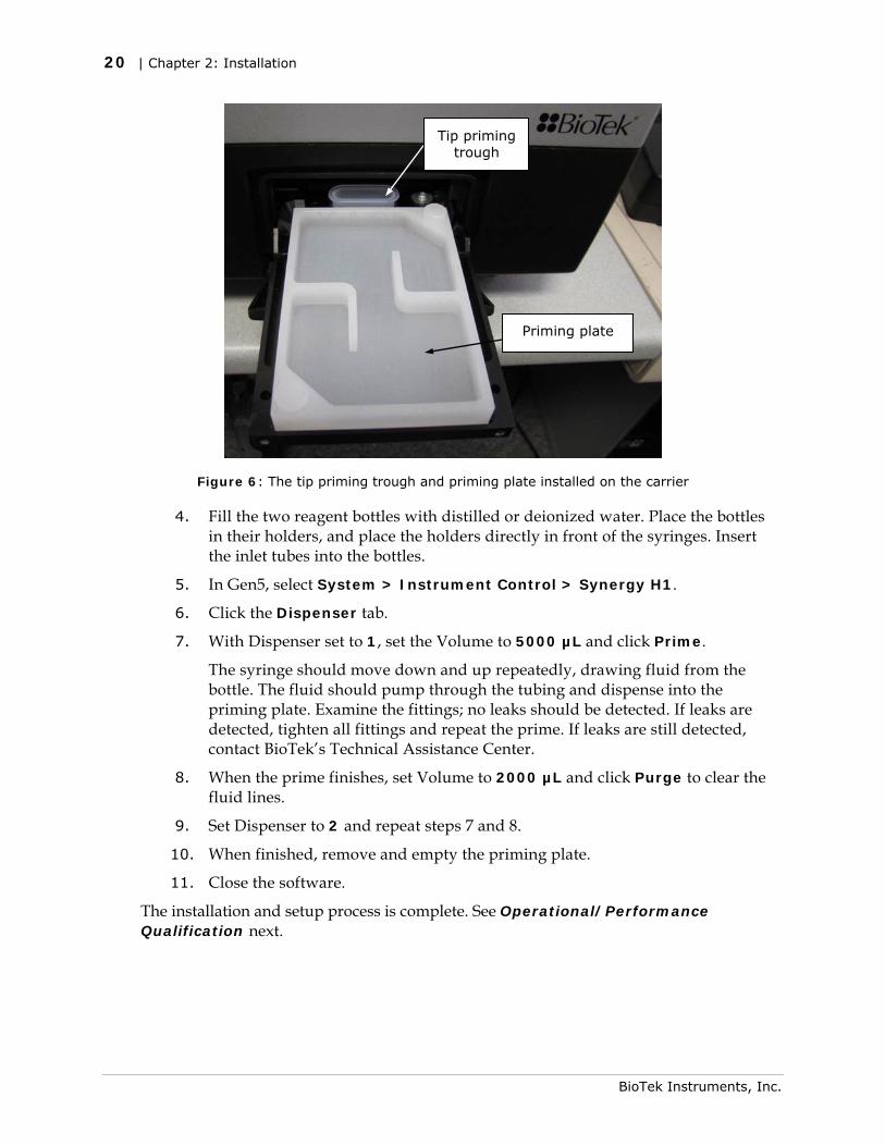
2. Place the tip priming trough in the rear pocket of the carrier.
3. Place the priming plate on the carrier.
Synergy H1 Operator’s Manual
20 | Chapter 2: Installation
Tip priming trough
Priming plate
Figure 6: The tip priming trough and priming plate installed on the carrier
4. Fill the two reagent bottles with distilled or deionized water. Place the bottles in their holders, and place the holders directly in front of the syringes. Insert the inlet tubes into the bottles.
5. In Gen5, select System > Instrument Control > Synergy H1.
6. Click the Dispenser tab.
7. With Dispenser set to 1, set the Volume to 5000 µL and click Prime.
The syringe should move down and up repeatedly, drawing fluid from the bottle. The fluid should pump through the tubing and dispense into the priming plate. Examine the fittings; no leaks should be detected. If leaks are detected, tighten all fittings and repeat the prime. If leaks are still detected, contact BioTek’s Technical Assistance Center.
8. When the prime finishes, set Volume to 2000 µL and click Purge to clear the fluid lines.
9. Set Dispenser to 2 and repeat steps 7 and 8.
10. When finished, remove and empty the priming plate.
11. Close the software.
The installation and setup process is complete. See Operational/Performance Qualification next.
BioTek Instruments, Inc.
Operational/Performance Qualification | 21
Operational/Performance Qualification
Your Synergy H1 was fully tested at BioTek prior to shipment and should operate properly following the successful completion of the installation and setup procedures described in this chapter.
If you suspect that problems occurred during shipment, if you received the reader back from BioTek following service or repair, or if regulatory requirements dictate that Operational/Performance Qualification is necessary, turn to Chapter 7, Instrument Qualification now to learn about BioTek’s recommended OQ/PQ procedures for the Synergy H1.
A Product Qualification & Maintenance (IQ/OQ/PQ) package for the Synergy H1 is available for purchase (PN 8040528). Contact your local BioTek dealer for more information.
Repackaging and Shipping Instructions
Important! Please read all of the information provided below before preparing the Synergy H1 for shipment.
If the reader and/or dispense module has been exposed to potentially hazardous material, decontaminate it to minimize the risk to all who come in contact with the reader during shipping, handling, and servicing. Decontamination prior to shipping is required by the U.S. Department of Transportation regulations. See Chapter 6, As Needed Maintenance for decontamination instructions.
Remove the microplate and tip prime trough (if equipped) from the carrier before shipment. Spilled fluids can contaminate the optics and damage the instrument.
The Synergy H1 with all available modules weighs up to 55 pounds (24.95 kg). Use two people when lifting and carrying the instrument.
Synergy H1 Operator’s Manual
22 | Chapter 2: Installation
The instrument’s packaging design is subject to change. If the instructions in this section do not appear to apply to the packaging materials you are using, please contact BioTek’s Technical Assistance Center for guidance.
Replace the shipping hardware before repackaging the reader. Please contact BioTek and order PN 8040015 if you have misplaced the carrier shipping bracket and/or the filter reader shipping bracket.
If you need to ship the Synergy H1 and/or the dispense module to BioTek for service or repair, be sure to use the original packaging materials. Other forms of commercially available packaging are not recommended and can void the warranty.
The shipping materials are designed to be used no more than five times. If the original materials have been damaged, lost, or used more than five times, contact BioTek to order replacements.
1. Contact BioTek’s Technical Assistance Center for an RMA (Return Materials
Authorization) number and the shipping address before returning equipment for service.
2. Decontaminate the reader and, if attached, the dispense module, according to the instructions provided in Chapter 6.
3. If you will also be shipping the dispense module, perform these steps described below in Preparing the Dispense Module for Shipment.
If you are not shipping the dispense module, disconnect it from the reader now.
4. If you have not already done so, retract the microplate carrier and then turn off and unplug the reader.
5. Install the carrier shipping bracket and, if applicable, the filter reader shipping bracket.
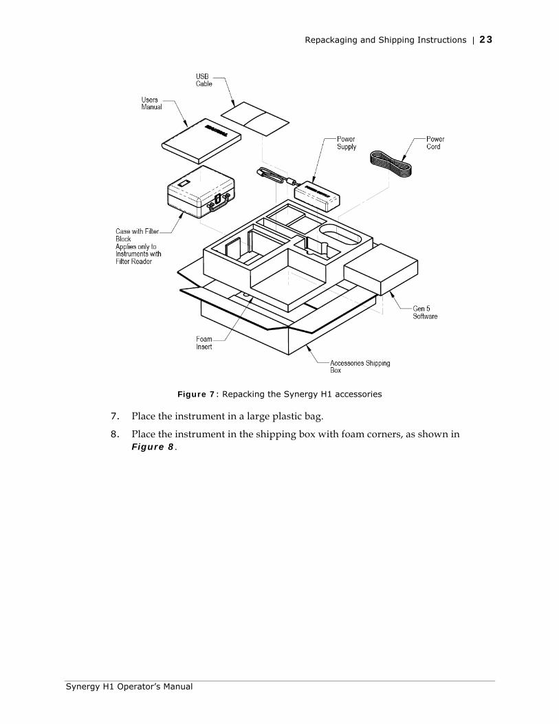
6. Place the accessories in the accessories box, as shown in Figure 7, then seal the accessories box with tape.
BioTek Instruments, Inc.
Repackaging and Shipping Instructions | 23
Figure 7: Repacking the Synergy H1 accessories
7. Place the instrument in a large plastic bag.
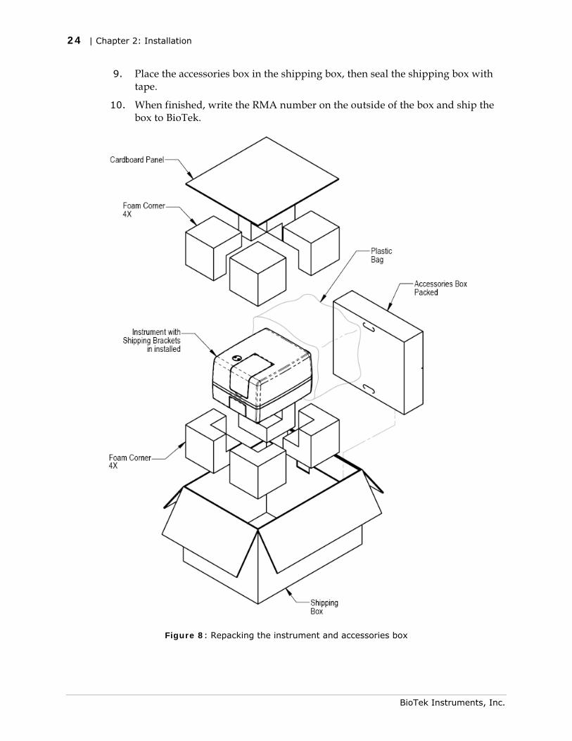
8. Place the instrument in the shipping box with foam corners, as shown in Figure 8.
Synergy H1 Operator’s Manual
24 | Chapter 2: Installation
9. Place the accessories box in the shipping box, then seal the shipping box with tape.
10. When finished, write the RMA number on the outside of the box and ship the box to BioTek.
Figure 8: Repacking the instrument and accessories box
BioTek Instruments, Inc.

Repackaging and Shipping Instructions | 25
Preparing the Dispense Module for Shipment
1. If you have not already done so, contact BioTek’s Technical Assistance Center for an RMA (Return Materials Authorization) number and the shipping address before returning equipment for service.
2. Decontaminate the module according to the instructions in Chapter 6. Be sure to purge the dispense module of all fluid when finished.
3. With the reader on, start Gen5 and select System > Instrument Control > Synergy H1.
4. Perform this step twice, for both dispensers: Click the Dispenser tab and set the dispenser number (1 or 2). Click Maintenance. The syringe bracket lowers. Remove the thumbscrew from underneath the bracket. Carefully unscrew the top of the syringe from the syringe valve. Lift out the syringe and store it in its original box.
5. Fully detach the dispense module from the reader. (The screws are stored in the plastic bag attached to the back of the module.) Set the module aside for the moment.
6. Remove the tip priming trough and store it in the dispenser accessories bag.
7. Remove the two inlet tubes from the syringe valves and store them in their plastic canisters.
8. Remove the two outlet tubes from the syringe valves. Attach the clear plastic shrouds to the fittings of the outlet tubes. Place the tubes in a plastic bag.
9. Remove the front cover from the dispenser.
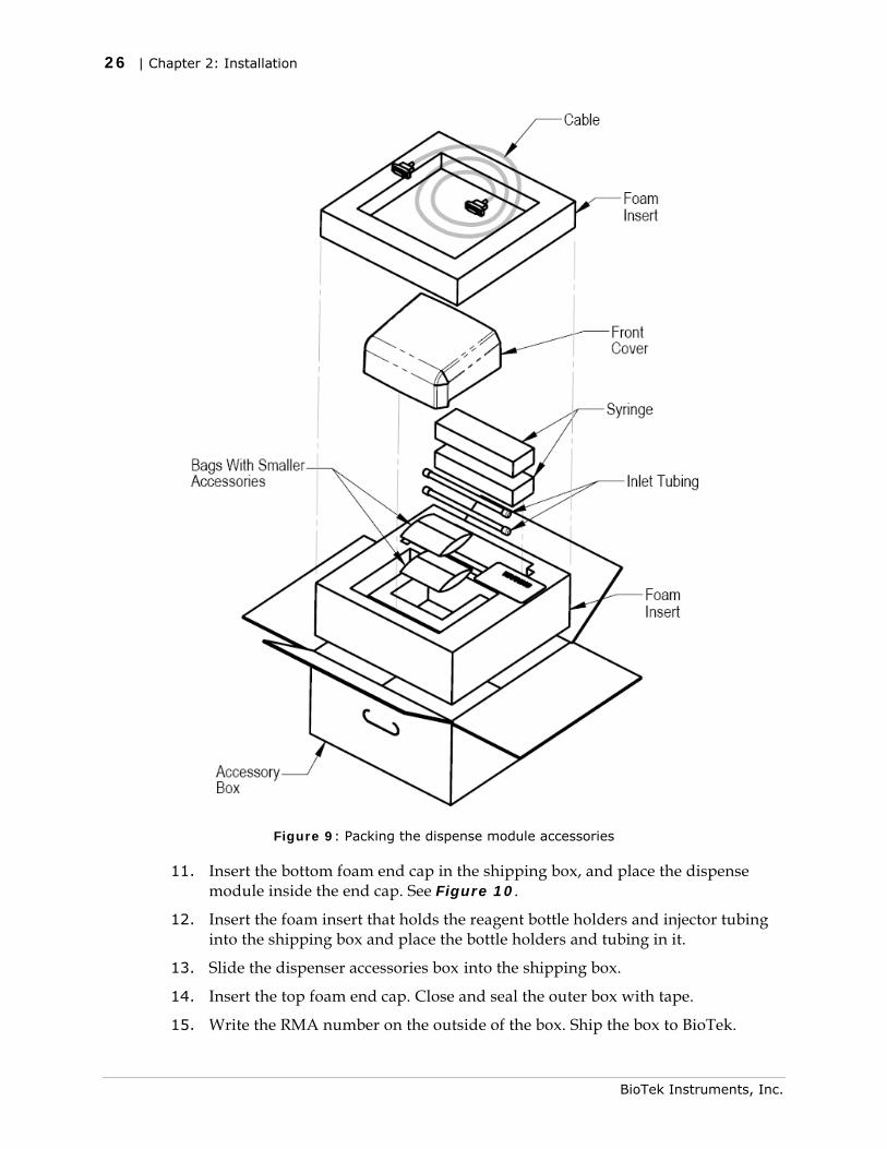
10. Insert the bottom foam end cap in the dispenser module accessories shipping box and place the accessories in the insert, as shown in Figure 9.
Synergy H1 Operator’s Manual
26 | Chapter 2: Installation
Figure 9: Packing the dispense module accessories
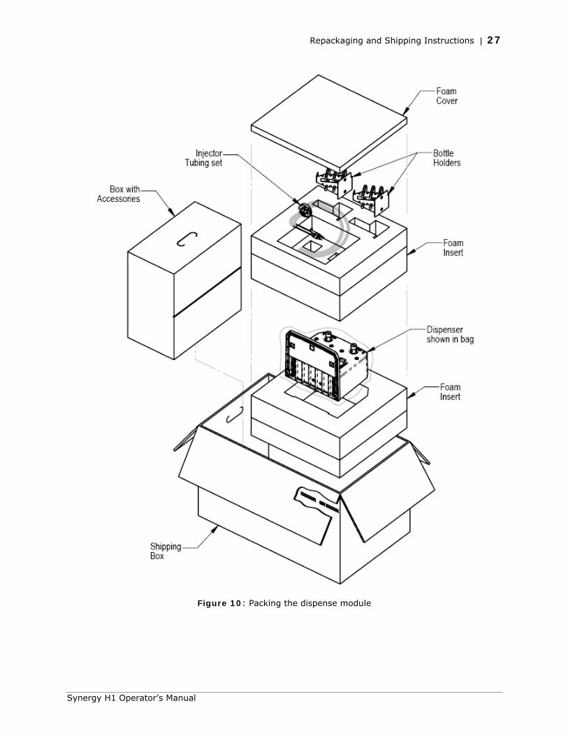
11. Insert the bottom foam end cap in the shipping box, and place the dispense module inside the end cap. See Figure 10.
12. Insert the foam insert that holds the reagent bottle holders and injector tubing into the shipping box and place the bottle holders and tubing in it.
13. Slide the dispenser accessories box into the shipping box.
14. Insert the top foam end cap. Close and seal the outer box with tape.
15. Write the RMA number on the outside of the box. Ship the box to BioTek.
BioTek Instruments, Inc.
Repackaging and Shipping Instructions | 27
Figure 10: Packing the dispense module
Synergy H1 Operator’s Manual

28 | Chapter 2: Installation
BioTek Instruments, Inc.
Chapter 3
Getting Started
This chapter describes some of the Synergy H1’s external and internal components, and provides an introduction to using BioTek Gen5 software to control the instrument.
Modular Design ............................................................... 30 External Components ....................................................... 31 Internal Components ........................................................ 31
Filter Cube ................................................................. 32 Injector System .......................................................... 33
Gen5 Software ................................................................ 36 Define the Filter Cube .................................................. 36 Protocols and Experiments ............................................ 37 Dispense Module Control .............................................. 38
Recommendations for Optimum Performance ....................... 39 General ...................................................................... 39 Luminescence Measurements ........................................ 40 Monochromator-Based Fluorescence Systems .................. 40 Models with Injectors ................................................... 40
30 | Chapter 3: Getting Started
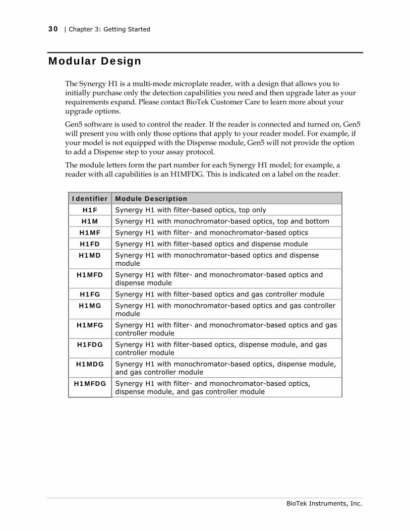
Modular Design
The Synergy H1 is a multi-mode microplate reader, with a design that allows you to initially purchase only the detection capabilities you need and then upgrade later as your requirements expand. Please contact BioTek Customer Care to learn more about your upgrade options.
Gen5 software is used to control the reader. If the reader is connected and turned on, Gen5 will present you with only those options that apply to your reader model. For example, if your model is not equipped with the Dispense module, Gen5 will not provide the option to add a Dispense step to your assay protocol.
The module letters form the part number for each Synergy H1 model; for example, a reader with all capabilities is an H1MFDG. This is indicated on a label on the reader.
Identifier Module Description
H1F Synergy H1 with filter-based optics, top only
H1M Synergy H1 with monochromator-based optics, top and bottom
H1MF Synergy H1 with filter- and monochromator-based optics
H1FD Synergy H1 with filter-based optics and dispense module
H1MD Synergy H1 with monochromator-based optics and dispense module
H1MFD Synergy H1 with filter- and monochromator-based optics and dispense module
H1FG Synergy H1 with filter-based optics and gas controller module
H1MG Synergy H1 with monochromator-based optics and gas controller module
H1MFG Synergy H1 with filter- and monochromator-based optics and gas controller module
H1FDG Synergy H1 with filter-based optics, dispense module, and gas controller module
H1MDG Synergy H1 with monochromator-based optics, dispense module, and gas controller module
H1MFDG Synergy H1 with filter- and monochromator-based optics, dispense module, and gas controller module
BioTek Instruments, Inc.
External Components | 31
Synergy H1 Operator’s Manual
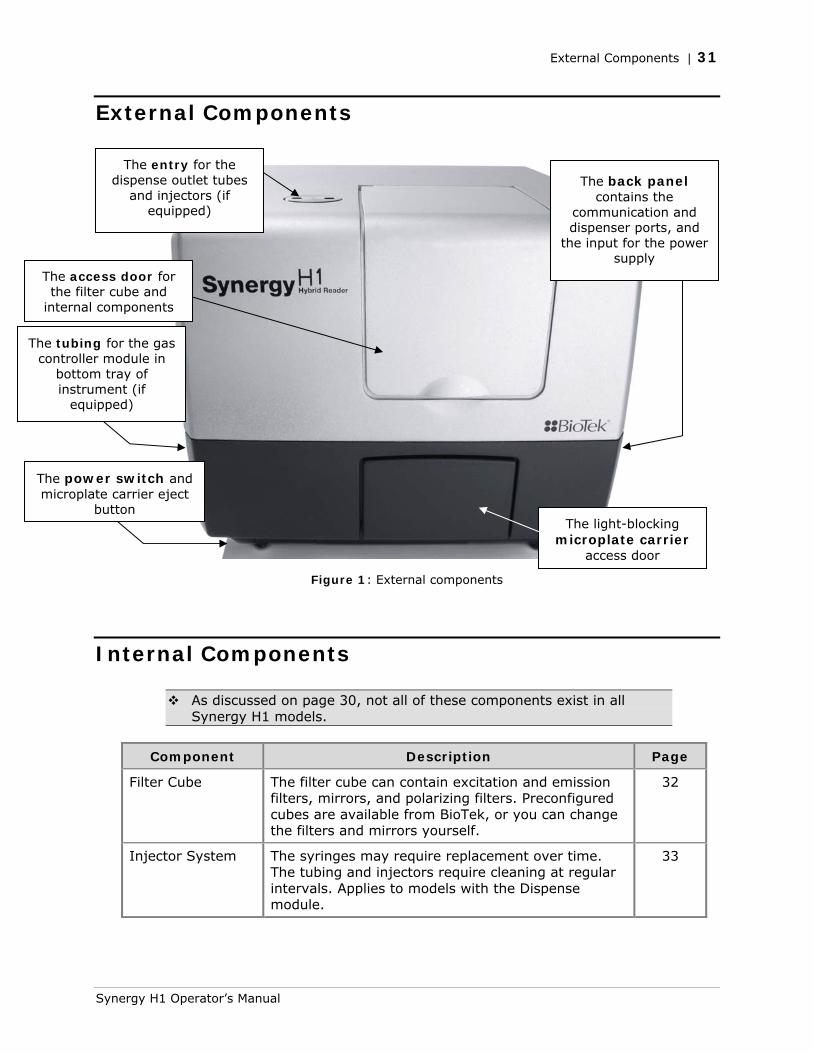
External Components
Figure 1: External components
Internal Components
As discussed on page 30, not all of these components exist in all Synergy H1 models.
Component Description Page
Filter Cube The filter cube can contain excitation and emission filters, mirrors, and polarizing filters. Preconfigured cubes are available from BioTek, or you can change the filters and mirrors yourself.
32
Injector System The syringes may require replacement over time. The tubing and injectors require cleaning at regular intervals. Applies to models with the Dispense module.
33
The power switch and microplate carrier eject
button
The access door for the filter cube and
internal components
The back panel contains the
communication and dispenser ports, and
the input for the power supply
The light-blocking microplate carrier
access door
The entry for the dispense outlet tubes
and injectors (if equipped)
The tubing for the gas controller module in
bottom tray of instrument (if
equipped)
32 | Chapter 3: Getting Started
Filter Cube
The Synergy H1 is equipped with a filter cube that contains excitation and emission filters, mirrors, and, if required, polarizing filters. Each filter cube contains two filter sets, each of which contains one excitation filter, one mirror, and one emission filter. The filter cube is accessed through a hinged door in the front of the instrument.
Do not open the door to access the filter cube during instrument operation. Doing so may result in invalid data.
The Gen5 Filter Cube Table must match the actual filter cube contents.
Excitation and Emission Filters
Gen5 keeps track of each cube’s contents and communicates this information to the instrument during operation. If you change the filter cube, you must update Gen5’s filter cube table (System > Instrument Configuration > Setup).
• Select Band Pass, Long Pass, or Short Pass, as appropriate for each filter type.
Band Pass, a standard interference filter with a defined central wavelength and bandwidth.
Long Pass, cutoff filters that transmit longer wavelengths and block shorter wavelengths.
Short Pass, cutoff filters that transmit shorter wavelengths and block longer wavelengths.
• Select PLUG to indicate the presence of a plug.
• Select HOLE to indicate an empty location.
Learn how to change the filter cube in Chapter 4, Filter and Mirrors.
See page 36 for information on updating the Gen5 Filter Cube Table.
Configuring the System for Luminescence Measurements • If your tests require that the light emitted from the samples remain unfiltered,
the Emission filter position in the filter cube should be empty.
• If you made any changes to the filter cube, you must update the Gen5 Filter Cube Table. Select PLUG to indicate the presence of a plug and HOLE to indicate an empty location.
BioTek Instruments, Inc.
Internal Components | 33
Mirrors
When taking filter-based fluorescence (FI, FP, or TRF) measurements from the top, the Synergy H1 uses mirrors to direct the excitation and emission light paths.
The mirrors are stored in the filter cube. The filter cube and the mirrors are user-changeable. That is, you can replace the entire filter cube with a different one; this is the BioTek recommended option. Alternatively, you can install different mirrors in the filter cube. Contact BioTek for more information on purchasing additional mirrors and filter cubes.
The Synergy H1’s filter cube stores up to two mirrors. There are two possible mirror types:
• A 50% mirror is a glass slide with silver dots. It works with any wavelength in the range of 200 to 850 nm.
• A dichroic mirror is wavelength specific: It requires the excitation and emission filters to fall within specific ranges. Dichroic mirrors provide better sensitivity than 50% mirrors, but they are dye-specific.
For models with Fluorescence Polarization (FP) capability, the filter cube is also equipped with a polarizing filter.
Learn more about mirrors, including how to change them, in Chapter 4, Filter and Mirrors.
Injector System
The tubing and injectors should be cleaned at least every three months. See Chapter 5, Preventive Maintenance, for instructions.
Inspect the injector system daily for leaks, preferably immediately after priming and whenever plumbing changes have been made.
If a syringe is leaking, it may need to be replaced. See Chapter 6, As Needed Maintenance, for instructions.
Synergy H1 Operator’s Manual
34 | Chapter 3: Getting Started
Dispense Module
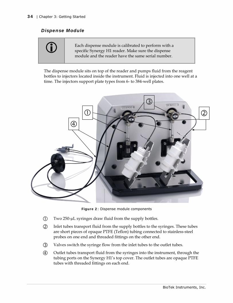
Each dispense module is calibrated to perform with a specific Synergy H1 reader. Make sure the dispense module and the reader have the same serial number.
The dispense module sits on top of the reader and pumps fluid from the reagent bottles to injectors located inside the instrument. Fluid is injected into one well at a time. The injectors support plate types from 6- to 384-well plates.
Figure 2: Dispense module components
Two 250-µL syringes draw fluid from the supply bottles.
Inlet tubes transport fluid from the supply bottles to the syringes. These tubes are short pieces of opaque PTFE (Teflon) tubing connected to stainless-steel probes on one end and threaded fittings on the other end.
Valves switch the syringe flow from the inlet tubes to the outlet tubes.
Outlet tubes transport fluid from the syringes into the instrument, through the tubing ports on the Synergy H1’s top cover. The outlet tubes are opaque PTFE tubes with threaded fittings on each end.
BioTek Instruments, Inc.
Internal Components | 35
Dispense Module Components and Materials Composition
Continuous contact with harsh chemicals is not recommended. Always rinse the fluid path with deionized water after contact with any strong acid, base, or solvent.
Components Material Composition
Tubing, syringe fittings PTFE (polytetrafluoroethylene)
Injector tips 316 stainless steel
Injector body PVC (polyvinyl chloride)
Priming plate and trough Polypropylene
Valve diaphragms Ethylene propylene (EPDM)
Valve body PEEK (polyether ether ketone)
Syringe barrel Borosilicate glass
See the Preventive Maintenance chapter for cleaning instructions
Priming the Injector System
Before running a Dispense assay, prime the system with the reagent or dispensing fluid. In addition, tip priming can be performed at the start of the assay and, sometimes, just before each dispense to a well. The tip prime compensates for any fluid loss at the injector tip due to evaporation since the last dispense. All priming activities are controlled via Gen5 (see page 38).
If the injector system is not primed adequately, air bubbles can get trapped in the system and affect injection volumes. Air bubbles in the system can also result in fluid spraying or scattering inside the reader.
Both types of primes require a fluid reservoir to be present on the microplate carrier:
• The priming plate is placed on the microplate carrier for a Prime operation (to prime the dispense system with fluid).
• The tip priming trough is placed in the rear pocket of the carrier, and is used for performing the Tip Prime before dispensing. The trough holds up to 1.5 mL of liquid and must be periodically emptied and cleaned by the user.
Do not perform tip priming when using tall plates. Generally, plates with fewer than 96 wells are too tall for error-free tip priming; and, tip priming is rarely required for these larger-volume plates.
The priming tray should be empty before priming and contain fluid after priming.
Synergy H1 Operator’s Manual
36 | Chapter 3: Getting Started
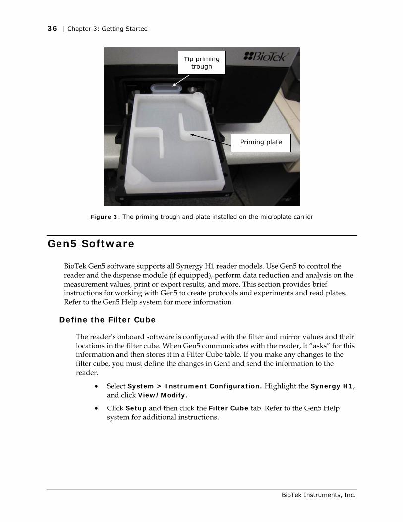
Tip priming trough
Priming plate
Figure 3: The priming trough and plate installed on the microplate carrier
Gen5 Software
BioTek Gen5 software supports all Synergy H1 reader models. Use Gen5 to control the reader and the dispense module (if equipped), perform data reduction and analysis on the measurement values, print or export results, and more. This section provides brief instructions for working with Gen5 to create protocols and experiments and read plates. Refer to the Gen5 Help system for more information.
Define the Filter Cube
The reader’s onboard software is configured with the filter and mirror values and their locations in the filter cube. When Gen5 communicates with the reader, it “asks” for this information and then stores it in a Filter Cube table. If you make any changes to the filter cube, you must define the changes in Gen5 and send the information to the reader.
• Select System > Instrument Configuration. Highlight the Synergy H1, and click View/Modify.
• Click Setup and then click the Filter Cube tab. Refer to the Gen5 Help system for additional instructions.
BioTek Instruments, Inc.
Gen5 Software | 37
Protocols and Experiments
In Gen5, a protocol contains instructions for controlling the reader and (optionally) instructions for analyzing the data retrieved from the reader. At a minimum, a protocol must specify the procedure for the assay you wish to run. After creating a protocol, create an experiment that references the protocol. You’ll run the experiment to read plates and analyze the data.
These instructions briefly describe how to create a protocol in Gen5. For more information, or if the instructions below do not match what you see in Gen5, refer to the Gen5 Getting Started Guide or help system.
1. Create a New Protocol.
• Gen5 version 2.x users: From the Task Manager, select Protocols > Create New.
• Gen5 version 1.x users: From the Welcome Screen, select Protocol.
2. Select Protocol > Procedure. If prompted to select a reader, select the Synergy H1 and click OK.
3. Select a Plate Type.
The assay plate must match the plate type selected in Gen5. Otherwise, the results of the read may be invalid.
4. Add Steps to the procedure for shaking or heating the plate, dispensing fluid, reading the plate, and more. Click Validate to verify that the reader supports the defined steps, and then click OK.
Optionally, perform the next steps to analyze and report the results:
5. Open the Plate Layout dialog and assign blanks, samples, controls, and/or standards to the plate.
6. Open the Data Reduction dialog to add data reduction steps. Categories include Transformation, Well Analysis, Curve Analysis, and more.
7. Create a report or export template, via one of the Report/Export Builder options.
8. Save the file with an identifying name.
For more information, or if the instructions below do not match what you see in Gen5, refer to the Gen5 Help System.
1. Create a New Experiment.
• Gen5 version 2.x users: From the Task Manager, select Experiments > Create using an existing protocol.
• Gen5 version 1.x users: From the Welcome Screen, select Experiment.
2. Select the desired protocol and click OK.
Synergy H1 Operator’s Manual
38 | Chapter 3: Getting Started
3. Select Plate > Read or click the Read Plate icon.
• Gen5 version 1.x only: The Plate Reading dialog will open. Enter any desired information, place the plate on the carrier, then click READ to begin the plate read. If the Save As dialog opens, enter a File name, choose a file location (Save in:) and click Save.
4. Click OK when the Load Plate dialog appears. The plate will be read.
5. When the read is complete, measurement values appear in Gen5. Use the Plate View to view the results. (Double-click a Plate in the menu tree to open the Plate View.) Select the desired data set (e.g., “485, 528”) from the Data drop-down list.
6. If you have not already done so, save the file with an identifying name.
Dispense Module Control
Applies only to models with injectors. Gen5 is used to perform several dispense module functions, such as initialize, dispense, prime, and purge. The Prime and Purge functions are introduced here. See the Gen5 Help system for more information.
Priming and purging routines are used to clean the fluid path; see also “Flushing/Purging the Fluid Path” in Preventive Maintenance.
Prime
Before running an experiment with a Dispense step, prime the system with the fluid to be used.
1. Place the priming plate on the carrier.
2. Fill the supply bottle with a sufficient volume of the fluid to be used for the prime and the assay. Insert the appropriate inlet tube into the bottle.
3. In Gen5, select System > Instrument Control > Synergy H1 and click the Dispenser tab.
4. Select the Dispenser number (1 or 2) associated with the supply bottle.
5. Enter the Volume to be used for the prime. The minimum recommended prime volume is 2000 µL.
6. Select a prime Rate, in µL/second.
7. Click Prime to start the process.
8. When finished, carefully remove the priming plate from the carrier and empty it.
If the priming plate is empty, the prime volume was too low.
BioTek Instruments, Inc.
Recommendations for Optimum Performance | 39
Purge
To save reagent, Gen5 provides the option to purge fluid from the system back into the supply bottle.
1. In Gen5, select System > Instrument Control > Synergy H1 and click the Dispenser tab.
2. Select the Dispenser number (1 or 2) associated with the supply bottle.
3. Enter the desired purge Volume in µL (e.g., 2000).
4. Select a prime Rate in µL/second.
5. Click Purge to start the process.
Recommendations for Optimum Performance
General
• Microplates should be clean and free from dust or bottom scratches. Use new microplates from sealed packages. Do not allow dust to settle on the surface of the solution; use microplate covers or seals when not reading the plate. Filter solutions to remove particulates that could cause erroneous readings.
• Although the Synergy H1 supports standard flat, U-bottom, and V-bottom microplates, the reader achieves optimum performance with flat-bottomed wells when running in Absorbance mode. See Appendix A, Specifications for more information on the supported plates.
• Non-uniformity in the optical density of the well bottoms can cause loss of accuracy, especially with U- and V-bottom polyvinyl microplates. Check for this by reading an empty microplate. Dual wavelength readings can eliminate this problem, or bring the variation in density readings to within acceptable limits for most measurements.
• Inaccuracy in pipetting has a large effect on measurements, especially if smaller volumes of liquid are used. For best results in most cases, use at least 100 μL per well in a 96-well plate and 25 µL in a 384-well plate.
• Pipetting solution into 384-well plates often traps air bubbles in the wells, which may result in inaccurate readings. A dual-wavelength reading method usually eliminates these inaccuracies. For best results, however, remove the air bubbles by degassing the plate in a vacuum chamber or spinning the plate in a centrifuge before reading.
• The inclination of the meniscus can cause loss of accuracy in some solutions, especially with small volumes. Shake the microplate before reading to help bring it within acceptable limits. Use Tween 20, if possible (or some other wetting agent) to normalize the meniscus for absorbance measurements. Some solutions develop
Synergy H1 Operator’s Manual
40 | Chapter 3: Getting Started
BioTek Instruments, Inc.
menisci over a period of several minutes. This effect varies with the brand of microplate and the solution composition. As the center of the meniscus drops and shortens the light path, the density readings change. The meniscus shape will stabilize over time.
• It is the user’s responsibility to understand the volumetric limits of the plate type in use as it applies to the assay being run.
Luminescence Measurements
For highly sensitive Luminescence assays using white plates, add a Delay step to your Procedure to “dark adapt” the plates in the Synergy H1’s reading chamber before taking measurements.
Monochromator-Based Fluorescence Systems
Although Time-Resolved Fluorescence can be performed with the monochromator, the filter-based fluorescence system is more sensitive for TRF and is the better choice.
Models with Injectors
• To keep the dispense system in top condition, flush and purge the fluid lines with deionized (DI) water every day or upon completion of an assay run, whichever is more frequent. Some reagents may crystallize or harden after use, clogging the fluid passageways. Flushing the tubing at the end of each day, letting the DI water soak, and then purging the lines at the beginning of each day ensures optimal performance of the dispense system. See the Preventive Maintenance chapter for more information.
• When dispensing volumes less than or equal to 20 µL/well, we recommend specifying a tip prime volume that is equal to the dispense volume. For dispense volumes greater than 20 µL/well, we recommend a tip prime volume of 20 µL.
• To avoid spillage and possible contamination of the instrument, empty the tip prime trough frequently and do not exceed the total fluid volume of the plate well when dispensing.
Chapter 4
Filters and Mirrors
Chapter 3, Getting Started provided an overview of the filters and mirrors installed in some Synergy H1 models. This chapter provides more detailed information on working with these components.
Filter Cube Overview ............................................................ 42 Removing a Filter Cube ..................................................... 44 Installing a Filter Cube...................................................... 44 Adding a Filter Cube to the Optics Library ............................ 44
Filters and Mirrors ................................................................ 46 Change the Filters and Mirrors ........................................... 46 Clean the Filters and Mirrors .............................................. 49 Filters Available from BioTek ............................................. 49 Mirrors Available from BioTek ............................................ 50
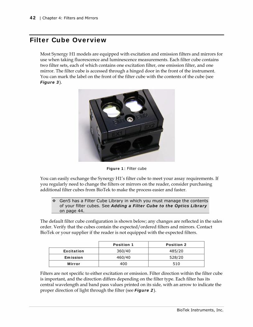
42 | Chapter 4: Filters and Mirrors
Filter Cube Overview
Most Synergy H1 models are equipped with excitation and emission filters and mirrors for use when taking fluorescence and luminescence measurements. Each filter cube contains two filter sets, each of which contains one excitation filter, one emission filter, and one mirror. The filter cube is accessed through a hinged door in the front of the instrument. You can mark the label on the front of the filter cube with the contents of the cube (see Figure 3).
Figure 1: Filter cube
You can easily exchange the Synergy H1’s filter cube to meet your assay requirements. If you regularly need to change the filters or mirrors on the reader, consider purchasing additional filter cubes from BioTek to make the process easier and faster.
Gen5 has a Filter Cube Library in which you must manage the contents of your filter cubes. See Adding a Filter Cube to the Optics Library on page 44.
The default filter cube configuration is shown below; any changes are reflected in the sales order. Verify that the cubes contain the expected/ordered filters and mirrors. Contact BioTek or your supplier if the reader is not equipped with the expected filters.
Position 1 Position 2
Excitation 360/40 485/20
Emission 460/40 528/20
Mirror 400 510
Filters are not specific to either excitation or emission. Filter direction within the filter cube is important, and the direction differs depending on the filter type. Each filter has its central wavelength and band pass values printed on its side, with an arrow to indicate the proper direction of light through the filter (see Figure 2).
BioTek Instruments, Inc.
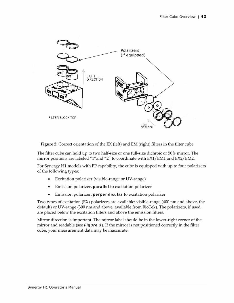
Filter Cube Overview | 43
Polarizers (if equipped)
Figure 2: Correct orientation of the EX (left) and EM (right) filters in the filter cube
The filter cube can hold up to two half-size or one full-size dichroic or 50% mirror. The mirror positions are labeled “1”and “2” to coordinate with EX1/EM1 and EX2/EM2.
For Synergy H1 models with FP capability, the cube is equipped with up to four polarizers of the following types:
• Excitation polarizer (visible-range or UV-range)
• Emission polarizer, parallel to excitation polarizer
• Emission polarizer, perpendicular to excitation polarizer
Two types of excitation (EX) polarizers are available: visible-range (400 nm and above, the default) or UV-range (300 nm and above, available from BioTek). The polarizers, if used, are placed below the excitation filters and above the emission filters.
Mirror direction is important. The mirror label should be in the lower-right corner of the mirror and readable (see Figure 3). If the mirror is not positioned correctly in the filter cube, your measurement data may be inaccurate.
Synergy H1 Operator’s Manual
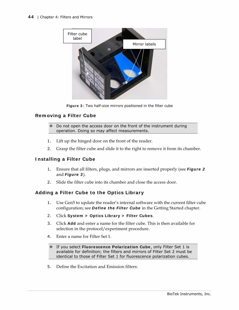
44 | Chapter 4: Filters and Mirrors
Filter cube label
Mirror labels
Figure 3: Two half-size mirrors positioned in the filter cube
Removing a Filter Cube
Do not open the access door on the front of the instrument during operation. Doing so may affect measurements.
1. Lift up the hinged door on the front of the reader.
2. Grasp the filter cube and slide it to the right to remove it from its chamber.
Installing a Filter Cube
1. Ensure that all filters, plugs, and mirrors are inserted properly (see Figure 2 and Figure 3).
2. Slide the filter cube into its chamber and close the access door.
Adding a Filter Cube to the Optics Library
1. Use Gen5 to update the reader’s internal software with the current filter cube configuration; see Define the Filter Cube in the Getting Started chapter.
2. Click System > Optics Library > Filter Cubes.
3. Click Add and enter a name for the filter cube. This is then available for selection in the protocol/experiment procedure.
4. Enter a name for Filter Set 1.
If you select Fluorescence Polarization Cube, only Filter Set 1 is available for definition; the filters and mirrors of Filter Set 2 must be identical to those of Filter Set 1 for fluorescence polarization cubes.
5. Define the Excitation and Emission filters:
BioTek Instruments, Inc.

Filter Cube Overview | 45
• Select Band Pass, Long Pass, or Short Pass and enter the wavelength and bandwidth.
• Select Plug to indicate the presence of a plug.
• Select Hole to indicate an empty location.
6. Select the mirror type and enter the excitation and emission ranges.
7. Define Filter Set 2, if necessary.
8. Click OK.
Synergy H1 Operator’s Manual
46 | Chapter 4: Filters and Mirrors
Filters and Mirrors
Synergy H1 is equipped with excitation and emission filters for obtaining fluorescence and luminescence measurements. The excitation filter selects the band of light to which the sample will be exposed. The emission filter selects the band of light with the maximum fluorescence signal of the sample, to be measured by the photomultiplier tube (PMT).
For filter-based, top-reading fluorescence analysis, the Synergy H1 uses mirrors to direct the excitation and emission light paths. Mirrors are required for fluorescence polarization (FP) measurements to direct light to the sample, because fibers cannot carry polarized light. Mirrors also provide increased gain/sensitivity for fluorescence intensity (FI) and time-resolved fluorescence (TRF) measurements.
Filters and mirrors are stored in the filter cube; see page 42 for an overview. You can replace the entire filter cube with a different one; this is the BioTek-recommended option. Alternatively, you can install different filters or mirrors in the cube. Contact BioTek for more information on purchasing additional filters and mirrors.
Change the Filters and Mirrors
You need the following tools to change a filter or mirror in a filter cube:
• 7/64" hex key
• Lens paper
• Cotton swab
• Linen or cloth gloves
When you change the filters and mirrors, update Gen5 with the new filter and mirror configuration (see Adding a Filter Cube to the Optics Library on page 44). It is critical that the Gen5 Filter Cube Table reflect the actual location and characteristics of the filters and mirrors in the installed filter cube.
If you accidently touch a mirror or polarizing filter, see the Preventive Maintenance chapter for cleaning instructions.
To remove a filter, plug, or mirror
1. Remove the filter cube as instructed on page 44.
2. Set the cube on the work surface. After you remove the filter cube top in step 4, the mirrors will fall out of the cube if the cube is not on a stable, flat surface.
3. Using a 7/64" hex key, remove the screw and washer located between the emission filter positions (Figure 4).
BioTek Instruments, Inc.
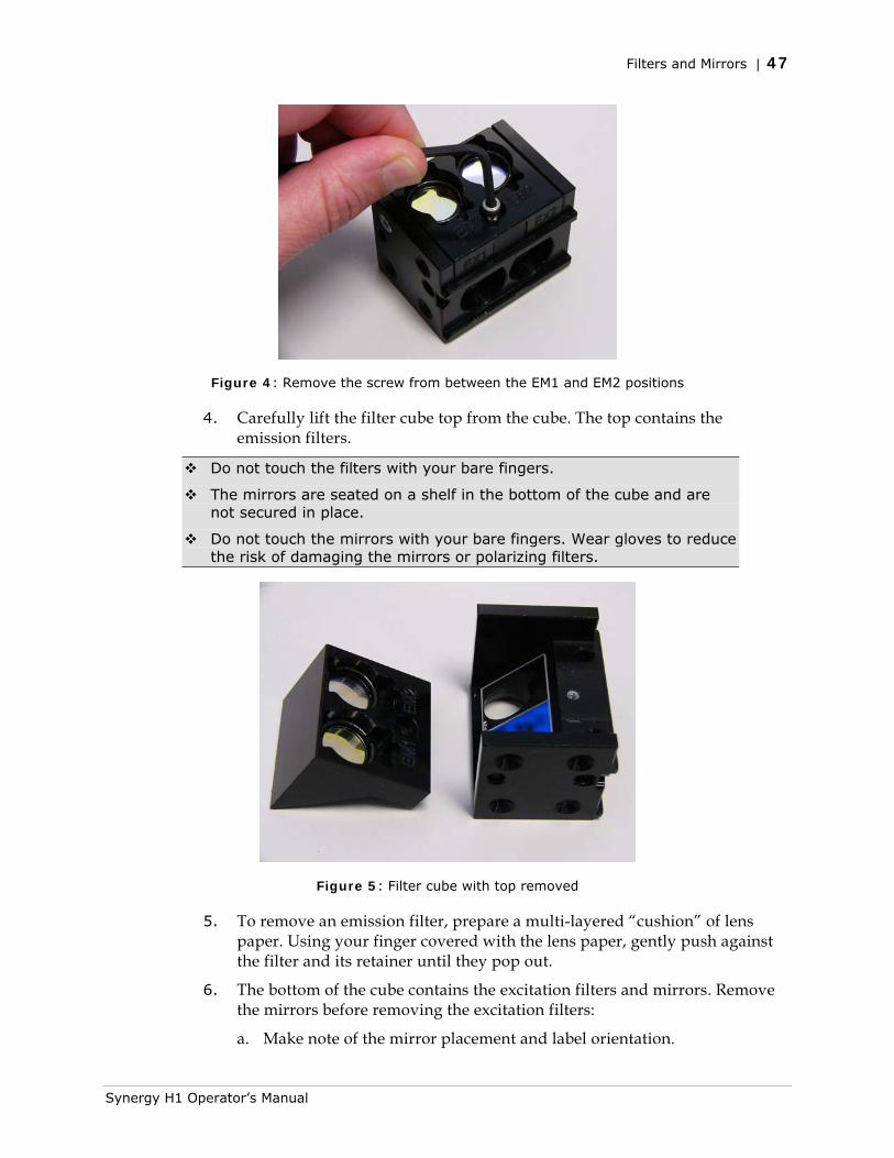
Filters and Mirrors | 47
Figure 4: Remove the screw from between the EM1 and EM2 positions
4. Carefully lift the filter cube top from the cube. The top contains the emission filters.
Do not touch the filters with your bare fingers.
The mirrors are seated on a shelf in the bottom of the cube and are not secured in place.
Do not touch the mirrors with your bare fingers. Wear gloves to reduce the risk of damaging the mirrors or polarizing filters.
Figure 5: Filter cube with top removed
5. To remove an emission filter, prepare a multi-layered “cushion” of lens paper. Using your finger covered with the lens paper, gently push against the filter and its retainer until they pop out.
6. The bottom of the cube contains the excitation filters and mirrors. Remove the mirrors before removing the excitation filters:
a. Make note of the mirror placement and label orientation.
Synergy H1 Operator’s Manual
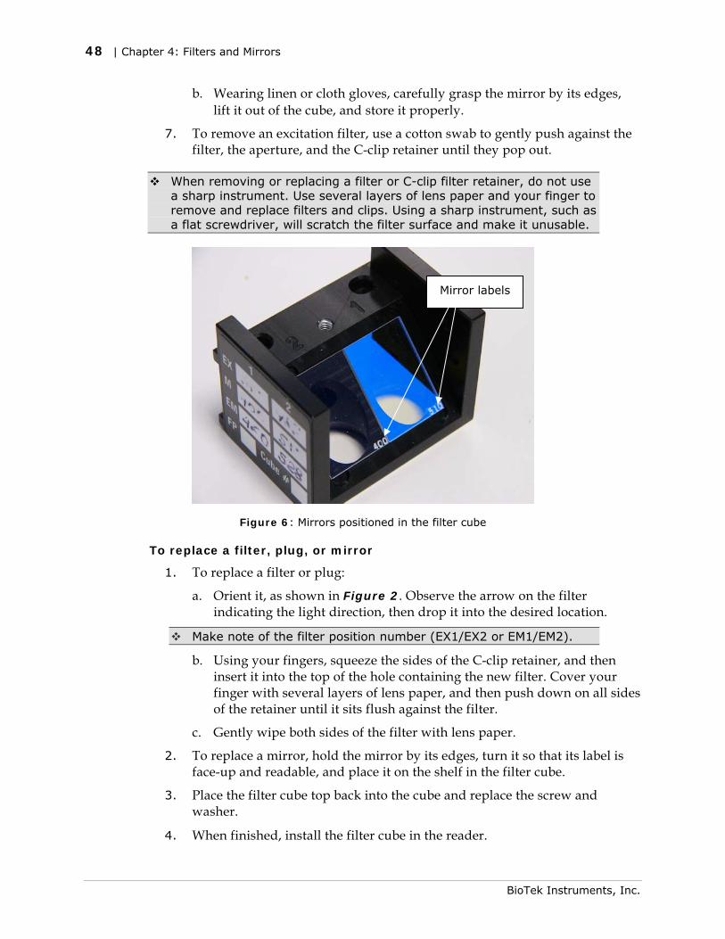
48 | Chapter 4: Filters and Mirrors
b. Wearing linen or cloth gloves, carefully grasp the mirror by its edges, lift it out of the cube, and store it properly.0
7. To remove an excitation filter, use a cotton swab to gently push against the filter, the aperture, and the C-clip retainer until they pop out.
When removing or replacing a filter or C-clip filter retainer, do not use a sharp instrument. Use several layers of lens paper and your finger to remove and replace filters and clips. Using a sharp instrument, such as a flat screwdriver, will scratch the filter surface and make it unusable.
Mirror labels
Figure 6: Mirrors positioned in the filter cube
To replace a filter, plug, or mirror
1. To replace a filter or plug:
a. Orient it, as shown in Figure 2. Observe the arrow on the filter indicating the light direction, then drop it into the desired location.
Make note of the filter position number (EX1/EX2 or EM1/EM2).
b. Using your fingers, squeeze the sides of the C-clip retainer, and then insert it into the top of the hole containing the new filter. Cover your finger with several layers of lens paper, and then push down on all sides of the retainer until it sits flush against the filter.
c. Gently wipe both sides of the filter with lens paper.
2. To replace a mirror, hold the mirror by its edges, turn it so that its label is face-up and readable, and place it on the shelf in the filter cube.
3. Place the filter cube top back into the cube and replace the screw and washer.
4. When finished, install the filter cube in the reader. 0
BioTek Instruments, Inc.
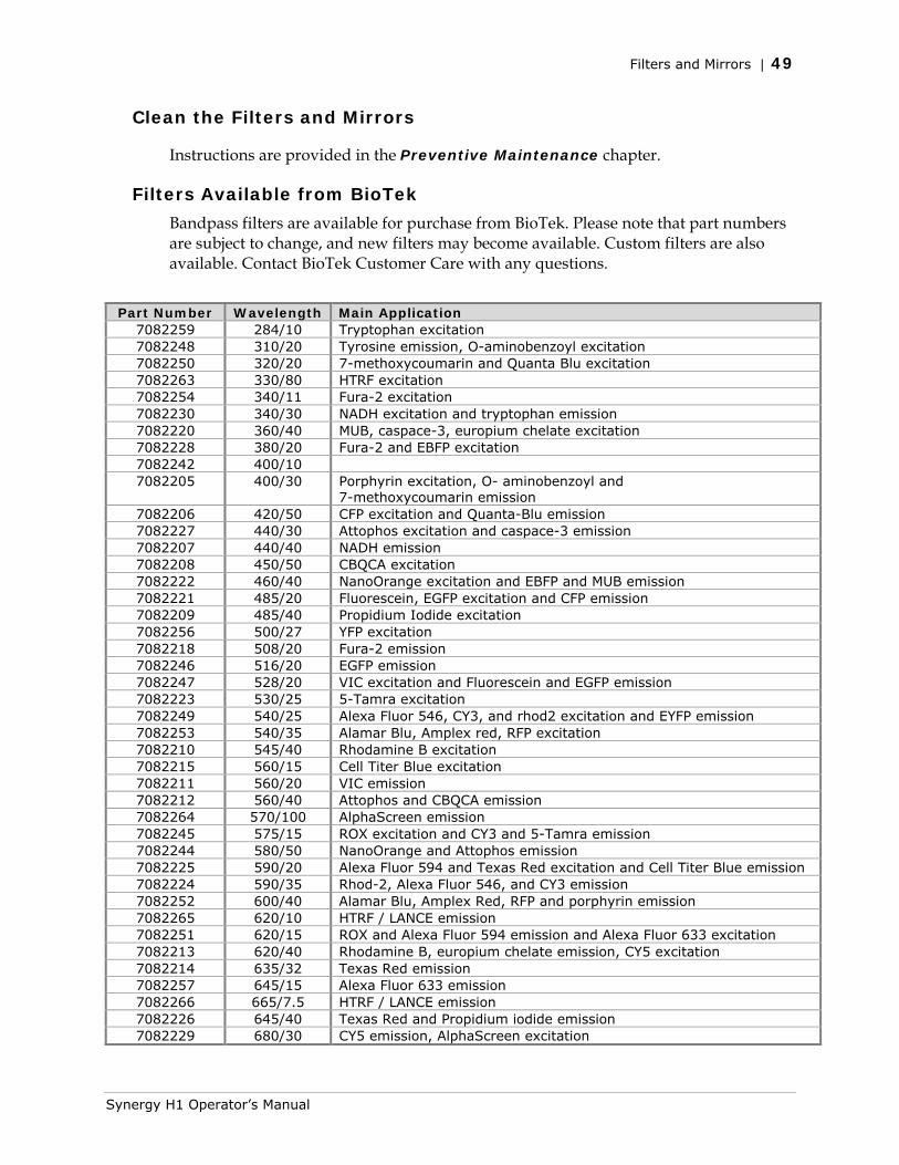
Filters and Mirrors | 49
Clean the Filters and Mirrors
Instructions are provided in the Preventive Maintenance chapter.
Filters Available from BioTek
Bandpass filters are available for purchase from BioTek. Please note that part numbers are subject to change, and new filters may become available. Custom filters are also available. Contact BioTek Customer Care with any questions.
Part Number Wavelength Main Application 7082259 284/10 Tryptophan excitation 7082248 310/20 Tyrosine emission, O-aminobenzoyl excitation 7082250 320/20 7-methoxycoumarin and Quanta Blu excitation 7082263 330/80 HTRF excitation 7082254 340/11 Fura-2 excitation 7082230 340/30 NADH excitation and tryptophan emission 7082220 360/40 MUB, caspace-3, europium chelate excitation 7082228 380/20 Fura-2 and EBFP excitation 7082242 400/10 7082205 400/30 Porphyrin excitation, O- aminobenzoyl and
7-methoxycoumarin emission 7082206 420/50 CFP excitation and Quanta-Blu emission 7082227 440/30 Attophos excitation and caspace-3 emission 7082207 440/40 NADH emission 7082208 450/50 CBQCA excitation 7082222 460/40 NanoOrange excitation and EBFP and MUB emission 7082221 485/20 Fluorescein, EGFP excitation and CFP emission 7082209 485/40 Propidium Iodide excitation 7082256 500/27 YFP excitation 7082218 508/20 Fura-2 emission 7082246 516/20 EGFP emission 7082247 528/20 VIC excitation and Fluorescein and EGFP emission 7082223 530/25 5-Tamra excitation 7082249 540/25 Alexa Fluor 546, CY3, and rhod2 excitation and EYFP emission 7082253 540/35 Alamar Blu, Amplex red, RFP excitation 7082210 545/40 Rhodamine B excitation 7082215 560/15 Cell Titer Blue excitation 7082211 560/20 VIC emission 7082212 560/40 Attophos and CBQCA emission 7082264 570/100 AlphaScreen emission 7082245 575/15 ROX excitation and CY3 and 5-Tamra emission 7082244 580/50 NanoOrange and Attophos emission 7082225 590/20 Alexa Fluor 594 and Texas Red excitation and Cell Titer Blue emission 7082224 590/35 Rhod-2, Alexa Fluor 546, and CY3 emission 7082252 600/40 Alamar Blu, Amplex Red, RFP and porphyrin emission 7082265 620/10 HTRF / LANCE emission 7082251 620/15 ROX and Alexa Fluor 594 emission and Alexa Fluor 633 excitation 7082213 620/40 Rhodamine B, europium chelate emission, CY5 excitation 7082214 635/32 Texas Red emission 7082257 645/15 Alexa Fluor 633 emission 7082266 665/7.5 HTRF / LANCE emission 7082226 645/40 Texas Red and Propidium iodide emission 7082229 680/30 CY5 emission, AlphaScreen excitation
Synergy H1 Operator’s Manual
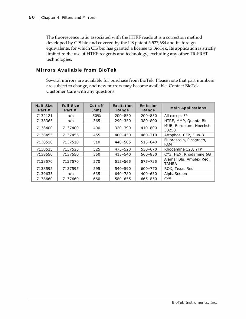
50 | Chapter 4: Filters and Mirrors
BioTek Instruments, Inc.
The fluorescence ratio associated with the HTRF readout is a correction method developed by CIS bio and covered by the US patent 5,527,684 and its foreign equivalents, for which CIS bio has granted a license to BioTek. Its application is strictly limited to the use of HTRF reagents and technology, excluding any other TR-FRET technologies.
Mirrors Available from BioTek
Several mirrors are available for purchase from BioTek. Please note that part numbers are subject to change, and new mirrors may become available. Contact BioTek Customer Care with any questions.
Half-Size Part #
Full-Size Part #
Cut-off (nm)
Excitation Range
Emission Range
Main Applications
7132121 n/a 50% 200–850 200–850 All except FP 7138365 n/a 365 290–350 380–800 HTRF, MMP, Quanta Blu
7138400 7137400 400 320–390 410–800 MUB, Europium, Hoechst 33258
7138455 7137455 455 400–450 460–710 Attophos, CFP, Fluo-3
7138510 7137510 510 440–505 515–640 Fluorescein, Picogreen, FAM
7138525 7137525 525 475–520 530–670 Rhodamine 123, YFP 7138550 7137550 550 415–540 560–850 CY3, HEX, Rhodamine 6G
7138570 7137570 570 515–565 575–735 Alamar Blu, Amplex Red, TAMRA
7138595 7137595 595 540–590 600–770 ROX, Texas Red 7139635 n/a 635 640–780 400–630 AlphaScreen 7138660 7137660 660 580–655 665–850 CY5

Chapter 5
Preventive Maintenance
This chapter provides instructions for maintaining the Synergy H1 and external dispense module (if used) in top condition, to ensure that they continue to perform to specification.
Preventive Maintenance .................................................... 52 Daily Cleaning for the Dispense Module .......................... 52 Schedule .................................................................... 53
Warnings and Precautions ................................................. 53 Clean Exposed Surfaces .................................................... 54 Inspect/Clean Excitation and Emission Filters ....................... 55 Inspect/Clean Mirrors ....................................................... 56
Materials .................................................................... 56 Procedure .................................................................. 56
Flush/Purge the Fluid Path ................................................ 58 Run a Dispense Protocol (Optional) .................................... 59 Empty/Clean the Tip Priming Trough .................................. 60 Clean the Priming Plate ..................................................... 60 Clean the Dispense Tubes and Injectors .............................. 61
Required Materials ....................................................... 61 Remove the Dispense Tubes and Injector Holders ............ 61 Clean the Dispense Tubes and Injectors ......................... 62
52 | Chapter 5: Preventive Maintenance
Preventive Maintenance
A general Preventive Maintenance regimen for all Synergy H1 models includes periodically cleaning all exposed surfaces and inspecting/cleaning the emission and excitation filters and mirrors (if used).
For models with the external dispense module, additional tasks include flushing/purging the fluid path, and cleaning the tip prime trough, priming plate, supply bottles, dispense tubing, and injectors.
Daily Cleaning for the Dispense Module
To ensure accurate performance and a long life for the dispense module and injectors, flush and purge the fluid lines with deionized (DI) water every day or after completing an assay run, whichever is more frequent. Some reagents may crystallize or harden after use and clog the fluid passageways. Take special care when using molecules that are active at very low concentrations (e.g., enzymes, inhibitors). Remove any residual reagent in the dispense lines using a suitable cleaning solution (review the reagent’s package insert for specific recommendations).
Flushing the tubing at the end of each day, letting the DI water soak overnight, and then purging the lines at the beginning of each day ensures optimal performance of the dispense system. BioTek recommends performing a visual inspection of the dispense accuracy before running an assay protocol that includes dispense steps.
BioTek also recommends flushing the module with DI water before conducting the decontamination procedure described in the As Needed Maintenance chapter.
Models with injectors: Accumulated algae, fungi, or mold may require decontamination. See the As Needed Maintenance chapter for complete decontamination instructions.
BioTek Instruments, Inc.
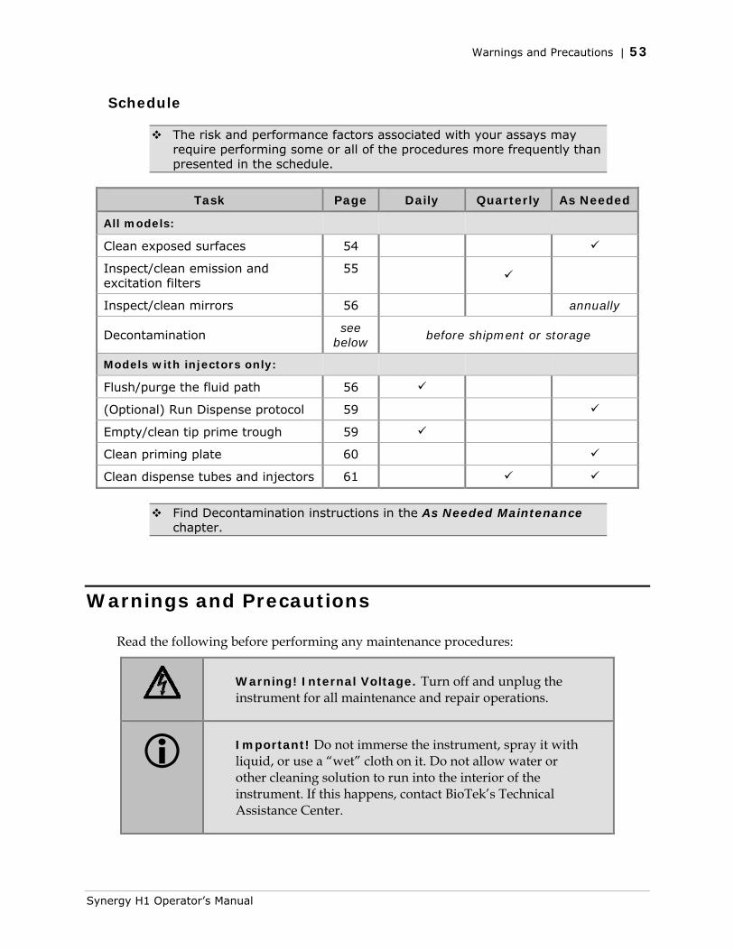
Warnings and Precautions | 53
Schedule
The risk and performance factors associated with your assays may require performing some or all of the procedures more frequently than presented in the schedule.
Task Page Daily Quarterly As Needed
All models:
Clean exposed surfaces 54
Inspect/clean emission and excitation filters
55
Inspect/clean mirrors 56 annually
Decontamination see
below before shipment or storage
Models with injectors only:
Flush/purge the fluid path 56
(Optional) Run Dispense protocol 59
Empty/clean tip prime trough 59
Clean priming plate 60
Clean dispense tubes and injectors 61
Find Decontamination instructions in the As Needed Maintenance chapter.
Warnings and Precautions
Read the following before performing any maintenance procedures:
Warning! Internal Voltage. Turn off and unplug the instrument for all maintenance and repair operations.
Important! Do not immerse the instrument, spray it with liquid, or use a “wet” cloth on it. Do not allow water or other cleaning solution to run into the interior of the instrument. If this happens, contact BioTek’s Technical Assistance Center.
Synergy H1 Operator’s Manual
54 | Chapter 5: Preventive Maintenance
Important! Do not apply lubricants to the microplate carrier or carrier track. Lubricant attracts dust and other particles, which may obstruct the carrier path and cause errors.
Warning! Wear protective gloves when handling contaminated instruments. Gloved hands should be considered contaminated at all times; keep gloved hands away from eyes, mouth, nose, and ears.
Warning! Mucous membranes are considered prime entry routes for infectious agents. Wear eye protection and a surgical mask when there is a possibility of aerosol contamination. Intact skin is generally considered an effective barrier against infectious organisms; however, small abrasions and cuts may not always be visible. Wear protective gloves when handling contaminated instruments.
Caution! The buildup of deposits left by the evaporation of spilled fluids within the read chamber can impact measurements. Be sure to keep System Test records before and after maintenance so that changes can be noted.
Warning! The instrument with all available modules weighs up to 55 pounds (24.95 kg). Use two people when lifting and carrying the instrument.
Clean Exposed Surfaces
Exposed surfaces may be cleaned (not decontaminated) with a cloth moistened (not soaked) with water or water and a mild detergent. You will need:
• Deionized or distilled water
• Clean, lint-free cotton cloths
• Mild detergent (optional)
1. Turn off and unplug the instrument.
BioTek Instruments, Inc.
Inspect/Clean Excitation and Emission Filters | 55
2. Moisten a clean cotton cloth with water, or with water and mild detergent. Do not soak the cloth.
3. Wipe the plate carrier and all exposed surfaces of the instrument.
4. Wipe all exposed surfaces of the dispense module (if used).
5. Wipe all exposed surfaces of the gas controller module (if used).
6. If detergent was used, wipe all surfaces with a cloth moistened with water.
7. Use a clean, dry cloth to dry all wet surfaces.
Models with injectors: If the Tip Priming Trough overflows or other spills occur inside the instrument, wipe the carrier and the surface beneath the carrier with a dry cotton cloth. The internal chamber and probes are not customer-accessible. If overflow is significant, contact BioTek’s Technical Assistance Center with any questions about your particular model.
Inspect/Clean Excitation and Emission Filters
Laboratory air is used to cool the lamp, and the filters can become dusty as a result. Filters should be inspected and cleaned at least every three months. You will need:
• Isopropyl, ethyl, or methyl alcohol
• 100% pure cotton balls or high-quality lens-cleaning tissue
• Cloth gloves
• Magnifying glass
Do not touch the filters with your bare fingers!
1. Turn off and unplug the instrument.
2. Open the access door on the front of the instrument. Slide the filter cube out of its compartment.
Chapter 4 contains illustrations for identifying the filters and their unique characteristics. It also contains instructions for replacing filters, if necessary.
3. Inspect the glass filters for speckled surfaces or a “halo” effect. This may indicate deterioration due to moisture exposure over a long period of time.
• If you have any concerns about the quality of the filters, contact your BioTek representative.
4. Using cotton balls or lens-cleaning tissue moistened with a small amount of high-quality alcohol, clean each filter by lightly stroking its surface in one direction. Ensure that the filters remain in their current locations.
Synergy H1 Operator’s Manual
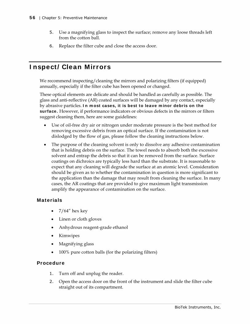
56 | Chapter 5: Preventive Maintenance
5. Use a magnifying glass to inspect the surface; remove any loose threads left from the cotton ball.
6. Replace the filter cube and close the access door.
Inspect/Clean Mirrors
We recommend inspecting/cleaning the mirrors and polarizing filters (if equipped) annually, especially if the filter cube has been opened or changed.
These optical elements are delicate and should be handled as carefully as possible. The glass and anti-reflective (AR) coated surfaces will be damaged by any contact, especially by abrasive particles. In most cases, it is best to leave minor debris on the surface. However, if performance indicators or obvious defects in the mirrors or filters suggest cleaning them, here are some guidelines:
• Use of oil-free dry air or nitrogen under moderate pressure is the best method for removing excessive debris from an optical surface. If the contamination is not dislodged by the flow of gas, please follow the cleaning instructions below.
• The purpose of the cleaning solvent is only to dissolve any adhesive contamination that is holding debris on the surface. The towel needs to absorb both the excessive solvent and entrap the debris so that it can be removed from the surface. Surface coatings on dichroics are typically less hard than the substrate. It is reasonable to expect that any cleaning will degrade the surface at an atomic level. Consideration should be given as to whether the contamination in question is more significant to the application than the damage that may result from cleaning the surface. In many cases, the AR coatings that are provided to give maximum light transmission amplify the appearance of contamination on the surface.
Materials
• 7/64” hex key
• Linen or cloth gloves
• Anhydrous reagent-grade ethanol
• Kimwipes
• Magnifying glass
• 100% pure cotton balls (for the polarizing filters)
Procedure
1. Turn off and unplug the reader.
2. Open the access door on the front of the instrument and slide the filter cube straight out of its compartment.
BioTek Instruments, Inc.
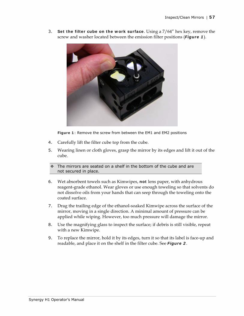
Inspect/Clean Mirrors | 57
3. Set the filter cube on the work surface. Using a 7/64” hex key, remove the screw and washer located between the emission filter positions (Figure 1).
Figure 1: Remove the screw from between the EM1 and EM2 positions
4. Carefully lift the filter cube top from the cube.
5. Wearing linen or cloth gloves, grasp the mirror by its edges and lift it out of the cube.
The mirrors are seated on a shelf in the bottom of the cube and are not secured in place.
6. Wet absorbent towels such as Kimwipes, not lens paper, with anhydrous reagent-grade ethanol. Wear gloves or use enough toweling so that solvents do not dissolve oils from your hands that can seep through the toweling onto the coated surface.
7. Drag the trailing edge of the ethanol-soaked Kimwipe across the surface of the mirror, moving in a single direction. A minimal amount of pressure can be applied while wiping. However, too much pressure will damage the mirror.
8. Use the magnifying glass to inspect the surface; if debris is still visible, repeat with a new Kimwipe.
9. To replace the mirror, hold it by its edges, turn it so that its label is face-up and readable, and place it on the shelf in the filter cube. See Figure 2.
Synergy H1 Operator’s Manual
58 | Chapter 5: Preventive Maintenance
Figure 2: Mirrors positioned in the filter cube
10. Place the filter cube top back onto the cube and replace the screw and washer.
11. When finished, reinstall the filter cube in the reader.
Flush/Purge the Fluid Path
Applies only to Synergy H1 models with injectors.
At the end of each day that the dispense module is in use, flush the fluid path using the Gen5 priming utility. Leave the fluid to soak overnight or over a weekend, and then purge the fluid before using the instrument again.
This flushing and purging routine is also recommended before disconnecting the outlet tubes from the reader, and before decontamination to remove any assay residue prior to applying isopropyl alcohol or sodium hypochlorite.
To flush the fluid path:
1. Fill two supply bottles with deionized or distilled water. Insert the supply (inlet) tubes into the bottles.
2. Place the priming plate on the carrier.
3. Select System > Instrument Control > Synergy H1.
4. Click the Dispenser tab and select Dispenser 1.
5. Set the Volume to 5000 µL. Keep the default prime rate.
BioTek Instruments, Inc.
Run a Dispense Protocol (Optional) | 59
6. Click Prime to start the process. When the process is complete, carefully remove the priming plate from the carrier and empty it.
7. Repeat the process for Dispenser 2.
Leave the water in the system overnight or until the instrument will be used again. Purge the fluid from the system (see below) and then prime with the dispense reagent before running an assay.
To purge the fluid from the system:
1. Place the inlet tubes in empty supply bottles or a beaker.
2. Select System > Instrument Control > Synergy H1.
3. Click the Dispenser tab and select Dispenser 1.
4. Set the Volume to 2000 µL.
5. Click Purge to start the process.
6. When the purge is complete, repeat the process for Dispenser 2.
After purging the system, you may wish to run a quick Dispense protocol to visually verify the dispense accuracy (see below) or the more thorough Dispense Accuracy and Precision Tests (see Chapter 7, Instrument Qualification).
Run a Dispense Protocol (Optional)
Applies only to Synergy H1 models with injectors.
After flushing/purging the system and before running an assay that requires dispense, visually inspect the dispensing accuracy.
1. Create a new protocol in Gen5. Set the Plate Type to match the plate you will use.
2. Add a Dispense step with the following parameters:
• Select Dispenser 1.
• Set Tip Priming to Before this dispense step and Volume to 10 µL.
• Set the Dispense Volume to 100 µL (or an amount to match your assay protocol).
• Adjust the Rate to support the dispensing volume.
3. Add another Dispense step with the same parameters; select Dispenser 2.
4. Add a quick Read step with the following parameters (Gen5 requires a Read step in a Dispense protocol):
• Select any Detection Method.
Synergy H1 Operator’s Manual
60 | Chapter 5: Preventive Maintenance
• Set the Read Type to Endpoint.
• Click the Full Plate button and highlight well A1.
• Select any wavelength or define one Filter Set.
5. Save the protocol with an identifying name, such as “Dispense Observation.”
6. Fill the reagent bottles with a DI H2O–Tween® solution (e.g., add 1 mL Tween® 20 to 1000 mL of deionized water).
7. Create and run an experiment based on the Dispense protocol.
8. Visually assess the fluid level in the wells for accuracy. If the well volume appears to be unevenly distributed, clean the internal dispense tubes and injectors as described in Clean the Internal Components beginning on page 61.
Empty/Clean the Tip Priming Trough
Applies only to Synergy H1 models with injectors.
The tip priming trough is a removable cup located in the rear pocket of the microplate carrier, used for performing the Tip Prime. The trough holds about 1.5 mL of liquid and must be periodically emptied and cleaned by the user. Gen5 will instruct you to do this at the start of an experiment that requires dispensing.
1. Extend the microplate carrier and carefully remove the tip priming trough from the carrier.
2. Wash the trough in hot, soapy water. Use a small brush to clean in the corners.
3. Rinse the trough thoroughly and allow it to dry completely.
4. Replace the trough in the microplate carrier.
Clean the Priming Plate
Applies only to Synergy H1 models with injectors.
Clean the priming plate regularly to prevent bacteria growth and residue buildup. Wash the plate in hot, soapy water, using a small brush to clean in the corners. Rinse thoroughly and allow it to dry completely.
BioTek Instruments, Inc.
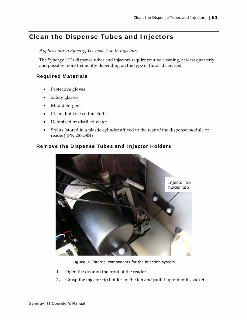
Clean the Dispense Tubes and Injectors | 61
Clean the Dispense Tubes and Injectors
Applies only to Synergy H1 models with injectors.
The Synergy H1’s dispense tubes and injectors require routine cleaning, at least quarterly and possibly more frequently depending on the type of fluids dispensed.
Required Materials
• Protective gloves
• Safety glasses
• Mild detergent
• Clean, lint-free cotton cloths
• Deionized or distilled water
• Stylus (stored in a plastic cylinder affixed to the rear of the dispense module or reader) (PN 2872304)
Remove the Dispense Tubes and Injector Holders
Injector tip holder tab
Figure 3: Internal components for the injection system
1. Open the door on the front of the reader.
2. Grasp the injector tip holder by the tab and pull it up out of its socket.
Synergy H1 Operator’s Manual
62 | Chapter 5: Preventive Maintenance
BioTek Instruments, Inc.
3. Using your fingers, remove the thumbscrews securing the light shield to the top of the reader and slide the shield up the outlets tubes.
4. Slide the injector tip holder through the hole in the top of the reader.
5. Turn each tube’s thumbscrew counterclockwise and gently pull each tube from its injector tip.
6. On the dispense module, turn each outlet tube’s thumbscrew counterclockwise to disconnect it from the injector.
Clean the Dispense Tubes and Injectors
As discussed on page 52, some reagents can crystallize and clog the tubing and injectors. Daily flushing and purging can help to prevent this, but more rigorous cleaning may be necessary if reagent has dried in the tubing or injectors.
To clean the dispense tubes, soak them in hot, soapy water to soften and dissolve any hardened particles. Flush each tube by holding it vertically under a stream of water.
To clean the injectors:
• Gently insert the stylus into each injector tip to clear any blockages. (The stylus is stored in a plastic cylinder affixed to the rear of the dispense module.)
• Stream water through the pipe to be sure it is clean. If the water does not stream out, try soaking in hot, soapy water and then reinserting the stylus.
Be careful not to bend the injector tips. A bent tip might not dispense accurately.

Chapter 6
As-Needed Maintenance
This chapter contains maintenance and component-replacement procedures that need to be performed only occasionally.
Decontamination ............................................................. 64 Required Materials ....................................................... 65 Procedure for Models without the Dispense Module .......... 65 Procedure for Models with the Dispense Module ............... 66
Routine Procedure................................................... 66 Clean Exposed Surfaces ...................................... 66 Decontaminate the Fluid Lines .............................. 67 Rinse the Fluid Lines ........................................... 68 Clean the Tubing and Injectors ............................. 68 Decontaminate the Tip Priming Trough and Priming Plate................................................................. 68
Alternate Procedure ................................................ 69 Dispense Module: Syringe Replacement .............................. 70
Syringe Maintenance Position ........................................ 70 Replace the Syringe ..................................................... 70
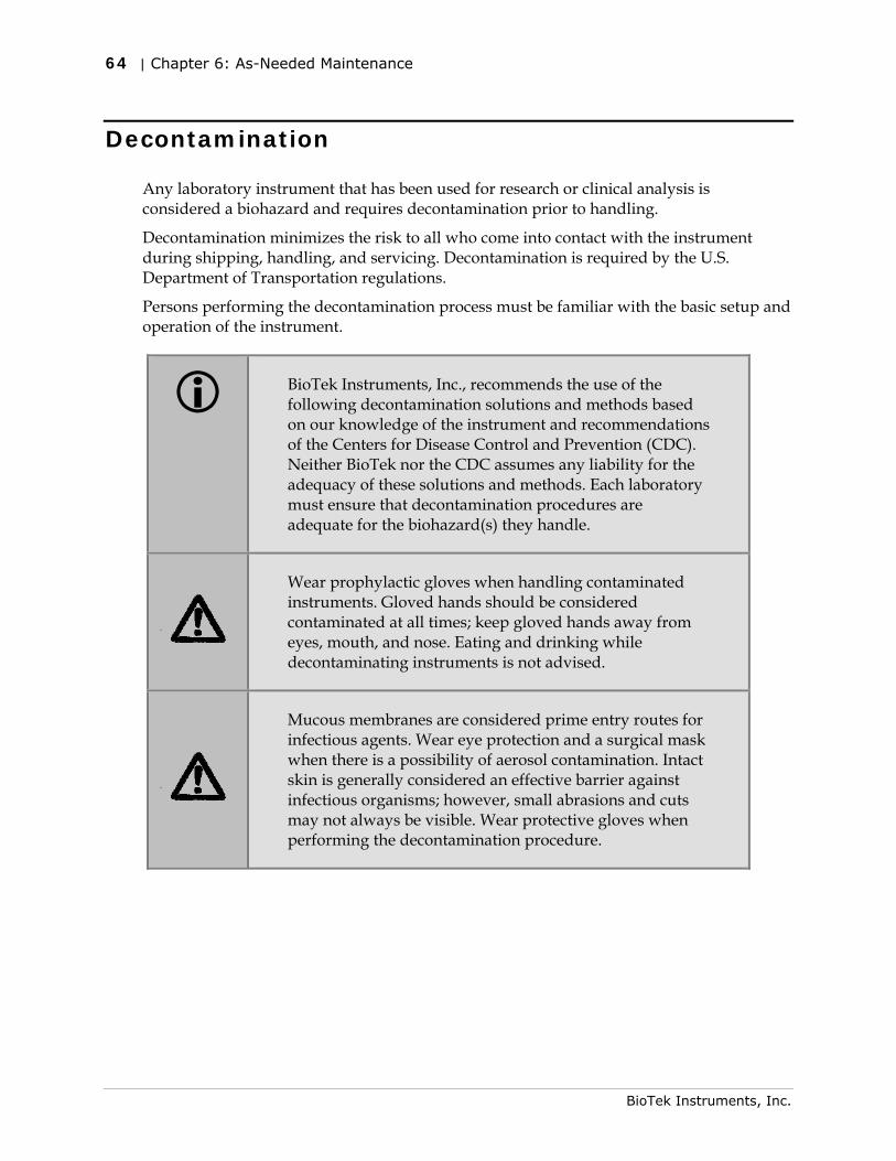
64 | Chapter 6: As-Needed Maintenance
Decontamination
Any laboratory instrument that has been used for research or clinical analysis is considered a biohazard and requires decontamination prior to handling.
Decontamination minimizes the risk to all who come into contact with the instrument during shipping, handling, and servicing. Decontamination is required by the U.S. Department of Transportation regulations.
Persons performing the decontamination process must be familiar with the basic setup and operation of the instrument.
BioTek Instruments, Inc., recommends the use of the following decontamination solutions and methods based on our knowledge of the instrument and recommendations of the Centers for Disease Control and Prevention (CDC). Neither BioTek nor the CDC assumes any liability for the adequacy of these solutions and methods. Each laboratory must ensure that decontamination procedures are adequate for the biohazard(s) they handle.
Wear prophylactic gloves when handling contaminated instruments. Gloved hands should be considered contaminated at all times; keep gloved hands away from eyes, mouth, and nose. Eating and drinking while decontaminating instruments is not advised.
Mucous membranes are considered prime entry routes for infectious agents. Wear eye protection and a surgical mask when there is a possibility of aerosol contamination. Intact skin is generally considered an effective barrier against infectious organisms; however, small abrasions and cuts may not always be visible. Wear protective gloves when performing the decontamination procedure.
BioTek Instruments, Inc.
Decontamination | 65
Required Materials
For all Synergy H1 models:
• Sodium hypochlorite (NaClO, or bleach)
• 70% isopropyl alcohol (as an alternative to bleach)
• Deionized or distilled water
• Safety glasses
• Surgical mask
• Protective gloves
• Lab coat
• Biohazard trash bags
• 125-mL beakers
• Clean, lint-free cotton cloths
Additional materials for models with the dispense module:
• Screwdriver
• Small brush for cleaning the tip priming trough and priming plate
• (Optional) Mild detergent
Procedure for Models without the Dispense Module
The sodium hypochlorite (bleach) solution is caustic; wear gloves and eye protection when handling the solution.
Do not immerse the instrument, spray it with liquid, or use a “wet” cloth. Do not allow the cleaning solution to run into the interior of the instrument. If this happens, contact the BioTek Service Department.
Turn off and unplug the instrument for all decontamination and cleaning operations.
1. Turn off and unplug the instrument.
2. Prepare an aqueous solution of 0.50% sodium hypochlorite (bleach). If the effects of bleach are a concern, 70% isopropyl alcohol may be used.
Synergy H1 Operator’s Manual
66 | Chapter 6: As-Needed Maintenance
Check the percent NaClO of the bleach you are using. Commercial bleach is typically 10.0% NaClO; prepare a 1:20 dilution. Household bleach is typically 5.0% NaClO; prepare a 1:10 dilution.
3. Moisten a cloth with the bleach solution or alcohol. Do not soak the cloth.
4. Open the plate carrier door and slide out the plate carrier.
5. Wipe the plate carrier and all exposed surfaces of the instrument.
6. Wait 20 minutes. Moisten a cloth with deionized (DI) or distilled water and wipe all surfaces of the instrument that have been cleaned with the bleach solution or alcohol.
7. Use a clean, dry cloth to dry all wet surfaces.
8. Reassemble the instrument as necessary.
9. Discard the used gloves and cloths using a biohazard trash bag and an approved biohazard container. 0.
Procedure for Models with the Dispense Module
Perform the Routine Procedure when the Synergy H1 is functioning normally. If you are unable to perform a prime due to a system failure, perform the Alternate Procedure described on page 69.
Routine Procedure
If disinfecting with sodium hypochlorite (bleach), be sure to flush repeatedly with deionized water to remove the bleach. After disinfecting with sodium hypochlorite, perform the rinse procedure provided on page 68.
If disinfecting with alcohol, do not immediately prime with deionized water, because the drying effect of the alcohol is an important aspect of its disinfectant properties.
Clean Exposed Surfaces
1. Turn off and unplug the instrument.
2. Prepare an aqueous solution of 0.50% sodium hypochlorite (bleach). If the effects of bleach are a concern, 70% isopropyl alcohol may be used.
Check the percent NaClO of the bleach you are using. Commercial bleach is typically 10.0% NaClO; prepare a 1:20 dilution. Household bleach is typically 5.0% NaClO; prepare a 1:10 dilution.
BioTek Instruments, Inc.
Decontamination | 67
3. Open the plate carrier door and slide out the plate carrier.
4. Moisten a cloth with the bleach solution or alcohol. Do not soak the cloth.
5. Wipe the plate carrier and the exposed surfaces of the external dispense module.
6. Wait 20 minutes. Moisten a cloth with deionized (DI) or distilled water and wipe all surfaces that have been cleaned with the bleach solution or alcohol.
7. Use a clean, dry cloth to dry all wet surfaces.
8. If the dispense module is installed, purge any fluid (see Flush/Purge the Fluid Path in Chapter 5) and detach the outlet tubes from the instrument. If it is not installed, attach only the dispense module’s communication cable to the instrument. Remove the supply bottles and their holders.
9. Perform the decontamination procedures described below.
Decontaminate the Fluid Lines
1. Place a beaker with 20 mL of 0.5% sodium hypochlorite solution or 70% isopropyl alcohol near SYRINGE 1 on the dispense module.
2. Place the SYRINGE 1 inlet tube in the beaker.
3. If you have not already done so, detach the dispense module’s outlet tubes from the instrument. Place the ends of the outlet tubes in an empty beaker and set the beaker next to the dispense module.
4. Launch Gen5, select System > Instrument Control, and click the Dispenser tab.
5. Select Dispenser 1, enter a Volume of 5000 µL, and keep the default dispense Rate.
6. Place the priming plate on the carrier.
7. Run two prime cycles, for a total of 10,000 µL.
8. Wait at least 20 minutes to allow the solution to disinfect the tubing.
9. Remove the inlet tube from the beaker of disinfectant solution.
10. From the Reader Control dialog, change the Volume to 1000 µL.
11. Run one prime cycle, to flush the disinfectant out of the fluid lines.
12. Empty the beaker containing the outlet tubes. Put the tubes back in the empty beaker.
13. If sodium hypochlorite (bleach) was used, perform Rinse the Fluid Lines.
Otherwise (or after performing the Rinse procedure), repeat steps 1–13 for SYRINGE 2/Dispenser 2.
Synergy H1 Operator’s Manual
68 | Chapter 6: As-Needed Maintenance
Rinse the Fluid Lines
Perform this procedure only if decontamination was performed using sodium hypochlorite.
1. Place a beaker containing at least 30 mL of deionized water on the dispense module.
2. Place the SYRINGE 1 or 2 inlet tube in the beaker.
3. If you have not already done so, place the outlet tubes in an empty beaker.
4. From the Reader Control dialog, select Dispenser 1 or 2, set the Volume to 5000 µL, and keep the default dispense Rate.
5. Run five prime cycles, for a total of 25,000 μL.
6. Pause for 10 minutes and then run one prime cycle with 5000 µL. This delay will allow any residual sodium hypochlorite to diffuse into the solution and be flushed out with the next prime.
7. Empty the beaker containing the outlet tubes.
8. Wipe all surfaces with deionized water.
9. Discard the used gloves and cloths using a biohazard trash bag and an approved biohazard container.
Clean the Tubing and Injectors
Perform the procedures under Clean the Tubing and Injectors in Chapter 5, Preventive Maintenance.
Decontaminate the Tip Priming Trough and Priming Plate
1. Remove the tip priming trough from the instrument’s microplate carrier.
2. Wash the tip priming trough and priming plate in hot, soapy water. Use a small brush or cloth to clean the corners of the trough and plate.
3. To decontaminate, soak the trough and plate in a container of 0.5% sodium hypochlorite or 70% isopropyl alcohol for at least 20 minutes.
• If decontaminating in a bleach solution, thoroughly rinse the trough and plate with DI water.
• If decontaminating with alcohol, let the trough and plate air dry.
4. Discard the used gloves and cloths using a biohazard trash bag and an approved biohazard container. 0
BioTek Instruments, Inc.
Decontamination | 69
Alternate Procedure
If you are unable to prime the Synergy H1 due to a system failure, decontaminate the instrument and the dispense module as follows:
1. Perform the procedures under Clean the Tubing and Injectors in Chapter 5, Preventive Maintenance.
2. Prepare an aqueous solution of 0.50% sodium hypochlorite (bleach). If the effects of bleach are a concern, 70% isopropyl alcohol may be used.
Check the percent NaClO of the bleach you are using. Commercial bleach is typically 10.0% NaClO; prepare a 1:20 dilution. Household bleach is typically 5.0% NaClO; prepare a 1:10 dilution.
3. Slide the microplate carrier out of the instrument.
4. Moisten a cloth with the bleach solution or alcohol. Do not soak the cloth.
5. Use the cloth to wipe:
• All exterior surfaces of the instrument
• All surfaces of the plate carrier
• The exposed surfaces of the dispense module, including the syringe valves
6. Remove the tubing and the syringes from the dispense module and soak them in the bleach or alcohol solution. Wait for 20 minutes.
7. Moisten a cloth with DI or distilled water and wipe all surfaces that have been cleaned with the bleach solution or alcohol.
8. Rinse all tubing and the syringes with DI water.
9. Use a clean, dry cloth to dry all surfaces on the instrument and the dispense module.
10. Reassemble the dispense module as necessary.
11. Discard the used gloves and cloths using a biohazard trash bag and an approved biohazard container.
Synergy H1 Operator’s Manual
70 | Chapter 6: As-Needed Maintenance
Dispense Module: Syringe Replacement
Refer to the Preventive Maintenance chapter for cleaning procedures you must perform regularly and also in the case of poor performance (for example, when Dispense Accuracy and Precision tests fail). If cleaning the dispense module does not eliminate performance problems, or if a syringe is obviously leaking, perform these instructions to replace a faulty syringe. Contact BioTek TAC to order replacement syringes.
To change a syringe, first use Gen5 to put the syringe in its maintenance position.
Syringe Maintenance Position
Do not change the syringe position or calibrate the dispensers unless instructed to do so as part of installation, upgrade, or maintenance.
Gen5 provides access to syringe setup functions for maintenance and calibration purposes. When a syringe needs to be installed or replaced, it must first be moved to its “maintenance position.”
1. In Gen5, select System > Instrument Control > Synergy H1 and click the Dispenser tab.
2. Select the appropriate Dispenser number (1 or 2) associated with the syringe.
3. Click Maintenance. The syringe plunger will move to its furthest-from-home position. The syringe can then be disconnected from the drive bracket and unscrewed from the valve.
Replace the Syringe
After using Gen5 to move the syringe into its maintenance position (refer to Figure 1):
1. Using your fingers, unscrew the bottom thumbscrew that secures the syringe, underneath the bracket. Retain this bottom thumbscrew; it is needed for the replacement syringe.
2. Unscrew the top thumbscrew to disengage the syringe from the valve.
3. Remove the new syringe from its protective box. (The syringe should already be assembled in one piece; if it is not, see “Install the Dispense Module” in the Installation chapter.)
BioTek Instruments, Inc.
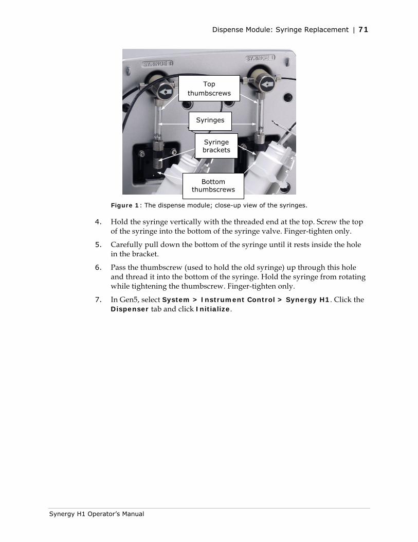
Dispense Module: Syringe Replacement | 71
Top thumbscrews
Syringes
Syringe brackets
Bottom thumbscrews
Figure 1: The dispense module; close-up view of the syringes.
4. Hold the syringe vertically with the threaded end at the top. Screw the top of the syringe into the bottom of the syringe valve. Finger-tighten only.
5. Carefully pull down the bottom of the syringe until it rests inside the hole in the bracket.
6. Pass the thumbscrew (used to hold the old syringe) up through this hole and thread it into the bottom of the syringe. Hold the syringe from rotating while tightening the thumbscrew. Finger-tighten only.
7. In Gen5, select System > Instrument Control > Synergy H1. Click the Dispenser tab and click Initialize.
Synergy H1 Operator’s Manual

72 | Chapter 6: As-Needed Maintenance
BioTek Instruments, Inc.
Chapter 7
Instrument Qualification
This chapter contains procedures for qualifying the initial and ongoing performance of the Synergy H1 and the external dispense module (if equipped).
Overview ........................................................................ 75 IQ/OQ/PQ ....................................................................... 75 Recommended Qualification Schedule ................................. 76 System Test .................................................................... 77 Absorbance Plate Test ...................................................... 83
Define Absorbance Test Plate Parameters ....................... 84 Run the Absorbance Plate Test ...................................... 85 Sample Absorbance Plate Test Report ............................ 86 Results and Troubleshooting Tips ................................... 88
Absorbance Liquid Tests ................................................... 89 Absorbance Liquid Test 1 .............................................. 89 Absorbance Liquid Test 2 .............................................. 92 Absorbance Liquid Test 3 (optional) ............................... 94
Fluorescence Liquid Tests .................................................. 97 Required Materials ....................................................... 98 Test Solutions ............................................................ 101 Procedure ................................................................. 103 Pipette Maps .............................................................. 104 Results Analysis ......................................................... 107 Troubleshooting ......................................................... 110 Gen5 Protocol Reading Parameters ............................... 111 Fluorescence Test Procedure (Methylumbelliferone) ......... 113
Luminescence Test .......................................................... 120 Harta Plate Test ......................................................... 120 Glowell Test ............................................................... 122 Gen5 Protocol Reading Parameters ............................... 123

74 | Chapter 7: Instrument Qualification
Troubleshooting ......................................................... 126 Dispense Module Tests .................................................... 127
Required Materials ...................................................... 128 Alternate Test Solutions .............................................. 128
BioTek Instruments, Inc.
Overview | 75
Overview
This chapter contains BioTek Instruments’ recommended Installation Qualification (IQ), Operational Qualification (OQ), and Performance Qualification (PQ) procedures for all models of the Synergy H1 Multi-Mode Microplate Reader.
Every Synergy H1 reader and external dispense module is fully tested at BioTek prior to shipment and should operate properly upon initial setup. If you suspect that a problem occurred during shipment, if you have received the equipment after returning it to the factory for service, and/or if regulatory requirements dictate that you qualify the equipment on a routine basis, perform the procedures outlined in this chapter.
A Product Qualification Package (PN 8040528) for the Synergy H1 is available for purchase. The package contains complete procedures, Gen5 protocols, checklists, and logbooks for performing Installation Qualification, Operational Qualification, Performance Qualification, and Preventive Maintenance. Contact your local BioTek dealer for more information.
If you are using the Gas Controller module, see the Gas Controller User Guide (PN 1211000) and the Gas Controller Production Qualification Package (1210512) for qualification instructions.
IQ/OQ/PQ
Installation Qualification confirms that the reader and its components have been supplied as ordered and ensures that they are assembled and configured properly for your lab environment.
• The recommended IQ procedure consists of setting up the instrument and its components as described in Chapter 2, Installation, and performing the System Test. For models with injectors, a quick “Injector Test” is also performed, to ensure that the dispense module is properly installed and there are no leaks.
• The IQ procedure should be performed initially (before the reader is used for the first time).
• The successful completion of the IQ procedure verifies that the instrument is installed correctly. The Operational Qualification procedure should be performed immediately following the successful IQ.
Synergy H1 Operator’s Manual
76 | Chapter 7: Instrument Qualification
Operational Qualification confirms that the equipment operates according to specification initially and over time.
• The recommended OQ procedure consists of performing the System Test, Absorbance Plate Test, Luminescence test, a series of Liquid Tests, and, if the external dispense module is used, the Dispense Accuracy and Precision Tests.
• The OQ procedure should be performed initially (before first use) and then routinely; the recommended interval is annually. It should also be performed after any major repair or upgrade to the hardware or software.
• Although out-of-tolerance failures will be detected by the OQ tests, results should be compared with those from the routine Performance Qualification tests and previous OQ tests to monitor for trends.
• The successful completion of the OQ procedure, in combination with results that are comparable to previous PQ and OQ tests, confirms that the equipment is operating according to specification initially and over time.
Performance Qualification confirms that the reader consistently meets the requirements of the tests performed at your laboratory.
• The recommended PQ procedure consists of performing the System Test, Absorbance Plate Test, Luminescence test, a series of Liquid Tests, and, if the external dispense module is used, the Dispense Accuracy and Precision Tests.
• Your facility’s operating policies may also require that you routinely perform an actual assay, to confirm that the reader will consistently give adequate results for the assays to be run on it.
• These tests should be performed routinely; the recommended interval is monthly or quarterly, depending on the test. This frequency may be adjusted depending on the trends observed over time.
• The successful completion of the PQ procedure confirms that the equipment is performing consistently under normal operating conditions.
Recommended Qualification Schedule
The schedule below defines BioTek-recommended intervals for qualifying a Synergy H1 used two to five days a week. The actual frequency, however, may be adjusted depending on your usage of the instrument and its various modules. This schedule assumes the reader is properly maintained as outlined in the Preventive Maintenance chapter.
BioTek Instruments, Inc.
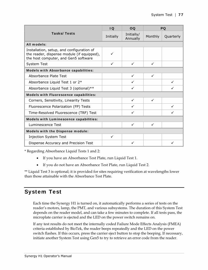
System Test | 77
Tasks/Tests IQ OQ PQ
Initially Initially/ Annually
Monthly Quarterly
All models:
Installation, setup, and configuration of the reader, dispense module (if equipped), the host computer, and Gen5 software
System Test Models with Absorbance capabilities:
Absorbance Plate Test Absorbance Liquid Test 1 or 2* Absorbance Liquid Test 3 (optional)** Models with Fluorescence capabilities:
Corners, Sensitivity, Linearity Tests Fluorescence Polarization (FP) Tests Time-Resolved Fluorescence (TRF) Test Models with Luminescence capabilities:
Luminescence Test Models with the Dispense module:
Injection System Test Dispense Accuracy and Precision Test
* Regarding Absorbance Liquid Tests 1 and 2:
• If you have an Absorbance Test Plate, run Liquid Test 1.
• If you do not have an Absorbance Test Plate, run Liquid Test 2.
** Liquid Test 3 is optional; it is provided for sites requiring verification at wavelengths lower than those attainable with the Absorbance Test Plate.
System Test
Each time the Synergy H1 is turned on, it automatically performs a series of tests on the reader’s motors, lamp, the PMT, and various subsystems. The duration of this System Test depends on the reader model, and can take a few minutes to complete. If all tests pass, the microplate carrier is ejected and the LED on the power switch remains on.
If any test results do not meet the internally coded Failure Mode Effects Analysis (FMEA) criteria established by BioTek, the reader beeps repeatedly and the LED on the power switch flashes. If this occurs, press the carrier eject button to stop the beeping. If necessary, initiate another System Test using Gen5 to try to retrieve an error code from the reader.
Synergy H1 Operator’s Manual
78 | Chapter 7: Instrument Qualification
Refer to Appendix B, Error Codes for information on error codes and for troubleshooting tips.
If the power-up System Test fails, when you initiate a System Test using Gen5, Gen5 displays a message stating that the reader has a pending system test report. Click OK in the message box to review the report; it contains information obtained up to the point of the failure.
1. Turn on the reader and launch Gen5.
2. If your assays use incubation, we recommend enabling Temperature Control and allowing the incubator to reach its set point before running the System Test. To access this feature, select System > Instrument Control and click the Pre-Heating tab.
3. Select System > Diagnostics > Run System Test.
If the test fails during execution, a message box appears in the software. Close the box; the test report contains the error code that was generated by the failure.
4. When the test is complete, a dialog appears, requesting additional information. Enter your user name and other information (if required) and then click OK.
5. The results report appears. Scroll down toward the bottom of the report; it shows either “SYSTEM TEST PASS” or “SYSTEM TEST FAIL *** ERROR (error code) DETECTED.”
6. Print the report if required.
• A sample test report is shown on the next few pages.
• Gen5 stores the results in a database, so the results can be retrieved at any time. We recommend that you print and save the reports to document that the test was performed.
7. If the test failed, look up the error code in Appendix B, Error Codes to determine its cause. If the cause is something you can fix, turn off the reader, fix the problem, and then turn the reader back on and retry the test.
If the test continues to fail, or if the cause is not something you can fix, contact BioTek’s Technical Assistance Center.
A sample test report for a Synergy H1 model with all modules installed is shown on the next few pages. Your instrument’s test report may be different. If you have any questions about the report’s contents or the test results, please print the report and then contact BioTek’s Technical Assistance Center.
BioTek Instruments, Inc.
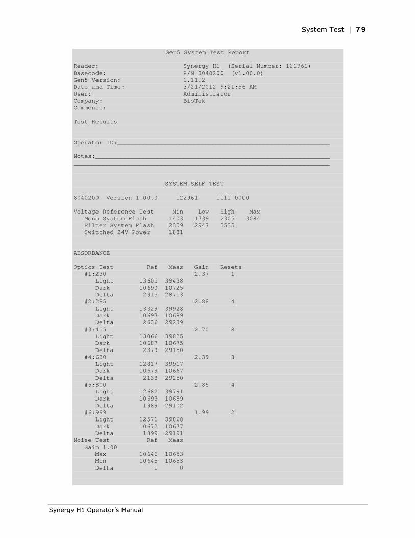
System Test | 79
Gen5 System Test Report Reader: Synergy H1 (Serial Number: 122961) Basecode: P/N 8040200 (v1.00.0) Gen5 Version: 1.11.2 Date and Time: 3/21/2012 9:21:56 AM User: Administrator Company: BioTek Comments: Test Results Operator ID:__________________________________________________________ Notes:________________________________________________________________ ______________________________________________________________________ SYSTEM SELF TEST 8040200 Version 1.00.0 122961 1111 0000 Voltage Reference Test Min Low High Max Mono System Flash 1403 1739 2305 3084 Filter System Flash 2359 2947 3535 Switched 24V Power 1881 ABSORBANCE Optics Test Ref Meas Gain Resets #1:230 2.37 1 Light 13605 39438 Dark 10690 10725 Delta 2915 28713 #2:285 2.88 4 Light 13329 39928 Dark 10693 10689 Delta 2636 29239 #3:405 2.70 8 Light 13066 39825 Dark 10687 10675 Delta 2379 29150 #4:630 2.39 8 Light 12817 39917 Dark 10679 10667 Delta 2138 29250 #5:800 2.85 4 Light 12682 39791 Dark 10693 10689 Delta 1989 29102 #6:999 1.99 2 Light 12571 39868 Dark 10672 10677 Delta 1899 29191 Noise Test Ref Meas Gain 1.00 Max 10646 10653 Min 10645 10653 Delta 1 0
Synergy H1 Operator’s Manual
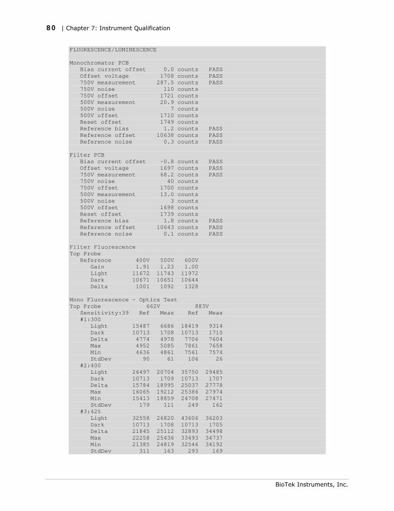
80 | Chapter 7: Instrument Qualification
FLUORESCENCE/LUMINESCENCE Monochromator PCB Bias current offset 0.0 counts PASS Offset voltage 1708 counts PASS 750V measurement 287.5 counts PASS 750V noise 110 counts 750V offset 1721 counts 500V measurement 20.9 counts 500V noise 7 counts 500V offset 1710 counts Reset offset 1749 counts Reference bias 1.2 counts PASS Reference offset 10638 counts PASS Reference noise 0.3 counts PASS Filter PCB Bias current offset -0.8 counts PASS Offset voltage 1697 counts PASS 750V measurement 68.2 counts PASS 750V noise 40 counts 750V offset 1700 counts 500V measurement 13.0 counts 500V noise 3 counts 500V offset 1698 counts Reset offset 1739 counts Reference bias 1.8 counts PASS Reference offset 10643 counts PASS Reference noise 0.1 counts PASS Filter Fluorescence Top Probe Reference 400V 500V 600V Gain 1.91 1.23 1.00 Light 11672 11743 11972 Dark 10671 10651 10644 Delta 1001 1092 1328 Mono Fluorescence - Optics Test Top Probe 662V 883V Sensitivity:39 Ref Meas Ref Meas #1:300 Light 15487 6686 18419 9314 Dark 10713 1708 10713 1710 Delta 4774 4978 7706 7604 Max 4952 5085 7861 7658 Min 4636 4861 7561 7574 StdDev 90 61 106 26 #2:400 Light 26497 20704 35750 29485 Dark 10713 1709 10713 1707 Delta 15784 18995 25037 27778 Max 16065 19212 25386 27974 Min 15413 18859 24708 27471 StdDev 179 111 249 162 #3:425 Light 32558 26820 43606 36203 Dark 10713 1708 10713 1705 Delta 21845 25112 32893 34498 Max 22258 25436 33493 34737 Min 21385 24819 32546 34192 StdDev 311 163 293 169
BioTek Instruments, Inc.

System Test | 81
#4:485 Light 29609 17058 38417 22716 Dark 10713 1709 10713 1709 Delta 18896 15349 27704 21007 Max 19287 15611 28269 21378 Min 18529 15140 26819 20430 StdDev 208 131 523 246 #5:535 Light 28155 12088 36355 16065 Dark 10713 1709 10713 1709 Delta 17442 10379 25642 14356 Max 17674 10524 26094 14463 Min 17124 10274 25135 14141 StdDev 190 82 331 86 #6:700 Light 16844 2663 19842 3062 Dark 10713 1708 10713 1708 Delta 6131 955 9129 1354 Max 6185 966 9252 1368 Min 6039 946 9007 1338 StdDev 42 7 99 9 Bottom Probe 662V 883V Sensitivity:45 Ref Meas Ref Meas #1:300 Light 15522 4603 18464 6119 Dark 10713 1710 10713 1709 Delta 4809 2893 7751 4410 Max 4913 2946 7917 4481 Min 4690 2839 7632 4356 StdDev 72 29 104 36 #2:400 Light 26365 19881 35718 28320 Dark 10713 1710 10713 1706 Delta 15652 18171 25005 26614 Max 16003 18387 25490 26966 Min 15266 17872 24655 26299 StdDev 224 173 282 231 #3:425 Light 32408 26996 43344 36132 Dark 10713 1707 10713 1704 Delta 21695 25289 32631 34428 Max 22184 25453 32958 34679 Min 21237 25128 32023 34080 StdDev 301 114 337 169 #4:485 Light 29451 18269 38459 24027 Dark 10712 1708 10713 1708 Delta 18739 16561 27746 22319 Max 19350 16690 28067 22455 Min 18338 16311 27250 22202 StdDev 322 119 303 70 #5:535 Light 28005 13453 36501 17726 Dark 10713 1710 10713 1707 Delta 17292 11743 25788 16019 Max 17601 11841 26090 16148 Min 16936 11619 25383 15936 StdDev 241 72 196 73 #6:700 Light 16817 2526 19895 2851 Dark 10713 1709 10713 1708 Delta 6104 817 9182 1143 Max 6187 825 9282 1158
Synergy H1 Operator’s Manual
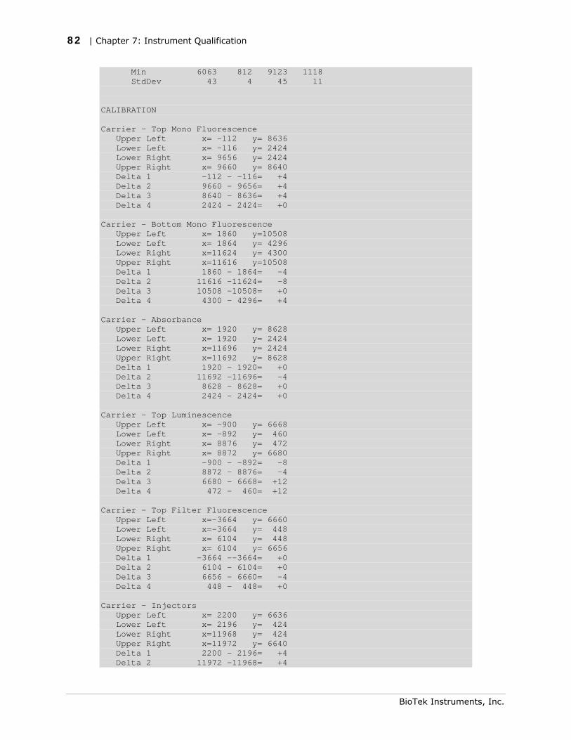
82 | Chapter 7: Instrument Qualification
Min 6063 812 9123 1118 StdDev 43 4 45 11 CALIBRATION Carrier - Top Mono Fluorescence Upper Left x= -112 y= 8636 Lower Left x= -116 y= 2424 Lower Right x= 9656 y= 2424 Upper Right x= 9660 y= 8640 Delta 1 -112 - -116= +4 Delta 2 9660 - 9656= +4 Delta 3 8640 - 8636= +4 Delta 4 2424 - 2424= +0 Carrier - Bottom Mono Fluorescence Upper Left x= 1860 y=10508 Lower Left x= 1864 y= 4296 Lower Right x=11624 y= 4300 Upper Right x=11616 y=10508 Delta 1 1860 - 1864= -4 Delta 2 11616 -11624= -8 Delta 3 10508 -10508= +0 Delta 4 4300 - 4296= +4 Carrier - Absorbance Upper Left x= 1920 y= 8628 Lower Left x= 1920 y= 2424 Lower Right x=11696 y= 2424 Upper Right x=11692 y= 8628 Delta 1 1920 - 1920= +0 Delta 2 11692 -11696= -4 Delta 3 8628 - 8628= +0 Delta 4 2424 - 2424= +0 Carrier - Top Luminescence Upper Left x= -900 y= 6668 Lower Left x= -892 y= 460 Lower Right x= 8876 y= 472 Upper Right x= 8872 y= 6680 Delta 1 -900 - -892= -8 Delta 2 8872 - 8876= -4 Delta 3 6680 - 6668= +12 Delta 4 472 - 460= +12 Carrier - Top Filter Fluorescence Upper Left x=-3664 y= 6660 Lower Left x=-3664 y= 448 Lower Right x= 6104 y= 448 Upper Right x= 6104 y= 6656 Delta 1 -3664 --3664= +0 Delta 2 6104 - 6104= +0 Delta 3 6656 - 6660= -4 Delta 4 448 - 448= +0 Carrier - Injectors Upper Left x= 2200 y= 6636 Lower Left x= 2196 y= 424 Lower Right x=11968 y= 424 Upper Right x=11972 y= 6640 Delta 1 2200 - 2196= +4 Delta 2 11972 -11968= +4
BioTek Instruments, Inc.
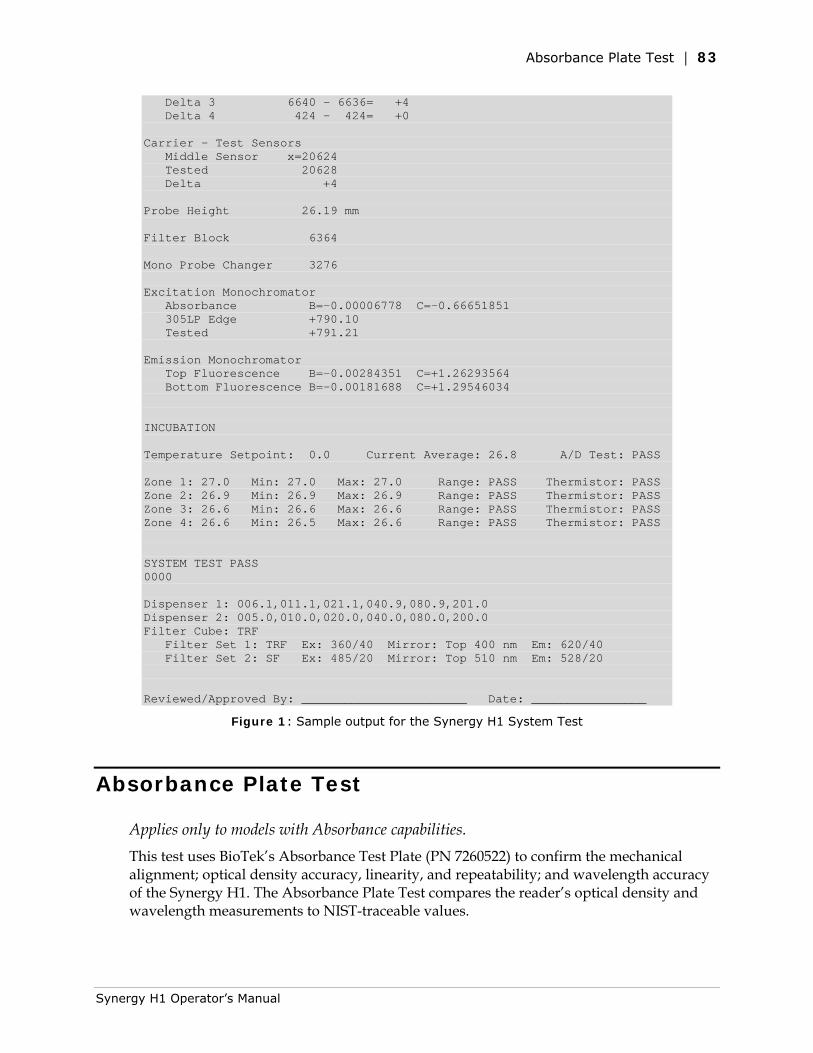
Absorbance Plate Test | 83
Delta 3 6640 - 6636= +4 Delta 4 424 - 424= +0 Carrier - Test Sensors Middle Sensor x=20624 Tested 20628 Delta +4 Probe Height 26.19 mm Filter Block 6364 Mono Probe Changer 3276 Excitation Monochromator Absorbance B=-0.00006778 C=-0.66651851 305LP Edge +790.10 Tested +791.21 Emission Monochromator Top Fluorescence B=-0.00284351 C=+1.26293564 Bottom Fluorescence B=-0.00181688 C=+1.29546034 INCUBATION Temperature Setpoint: 0.0 Current Average: 26.8 A/D Test: PASS Zone 1: 27.0 Min: 27.0 Max: 27.0 Range: PASS Thermistor: PASS Zone 2: 26.9 Min: 26.9 Max: 26.9 Range: PASS Thermistor: PASS Zone 3: 26.6 Min: 26.6 Max: 26.6 Range: PASS Thermistor: PASS Zone 4: 26.6 Min: 26.5 Max: 26.6 Range: PASS Thermistor: PASS SYSTEM TEST PASS 0000 Dispenser 1: 006.1,011.1,021.1,040.9,080.9,201.0 Dispenser 2: 005.0,010.0,020.0,040.0,080.0,200.0 Filter Cube: TRF Filter Set 1: TRF Ex: 360/40 Mirror: Top 400 nm Em: 620/40 Filter Set 2: SF Ex: 485/20 Mirror: Top 510 nm Em: 528/20 Reviewed/Approved By: _______________________ Date: ________________
Figure 1: Sample output for the Synergy H1 System Test
Absorbance Plate Test
Applies only to models with Absorbance capabilities. This test uses BioTek’s Absorbance Test Plate (PN 7260522) to confirm the mechanical alignment; optical density accuracy, linearity, and repeatability; and wavelength accuracy of the Synergy H1. The Absorbance Plate Test compares the reader’s optical density and wavelength measurements to NIST-traceable values.
Synergy H1 Operator’s Manual

84 | Chapter 7: Instrument Qualification
An alternate method for confirming accuracy, linearity, and repeatability is Liquid Test 2, described on page 92.
To run this test, you will need BioTek’s Absorbance Test Plate (PN 7260522), with its accompanying data sheet.
• The Absorbance OD Standards section contains NIST-traceable standard OD values for the filters at several different wavelengths. We recommend testing at six wavelengths; those at or close to the wavelengths used in your assays.
• The Wavelength Accuracy Standards section contains Expected Peak wavelength values for the filter in position C6 on the plate. Each value has a valid test range associated with it. For example, an Expected Peak value may be 586 nm with tolerance values of –6/+4 (or a test range of 580 to 590 nm).
The instructions provided below are guidelines. Refer to the Gen5 Help system for more information.
Define Absorbance Test Plate Parameters
1. Obtain the data sheet that came with the Test Plate.
2. Start Gen5 and select System > Diagnostics > Test Plates > Add/Modify Plates.
3. Click Add. The Absorbance Test Plate dialog appears.
4. Select the appropriate Plate Type and enter the plate’s serial number.
5. Enter the Last Certification and Next Certification dates from the calibration sticker on the Test Plate.
6. If the wavelength values in the top row of the grid in Gen5 are appropriate for your tests, enter the OD values from the data sheet into the grid. Make sure you enter the correct value for each well/wavelength combination.
If you need to change the wavelength values, click Wavelength List. Click the Gen5 Help button for assistance.
7. Select the number of Peak Wavelength tests to run (up to 4), based on the number of expected peak wavelength values provided on the certificate.
8. Enter the Expected Peak value(s) from the certificate and set the Test Range – and + values.
• If the C6 filter is Holmium or Erbium glass, the certificate contains two Spectral Bandpass tables. The Synergy H1 has a bandpass wider than 5 nm for wavelengths greater than 285 nm and less than 4 nm for 230–285 nm. As a result, we recommend you use the expected peak values in the 5.0 nm table for your tests.
For the Erbium glass, any peak can be used.
BioTek Instruments, Inc.
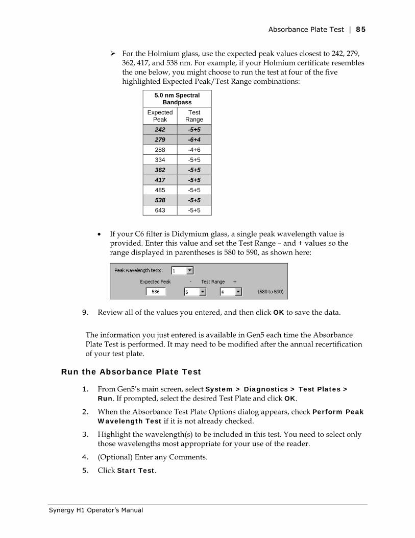
Absorbance Plate Test | 85
For the Holmium glass, use the expected peak values closest to 242, 279, 362, 417, and 538 nm. For example, if your Holmium certificate resembles the one below, you might choose to run the test at four of the five highlighted Expected Peak/Test Range combinations:
5.0 nm Spectral Bandpass
Expected Peak
Test Range
242 -5+5 279 -6+4 288 -4+6 334 -5+5 362 -5+5 417 -5+5 485 -5+5 538 -5+5 643 -5+5
• If your C6 filter is Didymium glass, a single peak wavelength value is provided. Enter this value and set the Test Range – and + values so the range displayed in parentheses is 580 to 590, as shown here:
9. Review all of the values you entered, and then click OK to save the data.
The information you just entered is available in Gen5 each time the Absorbance Plate Test is performed. It may need to be modified after the annual recertification of your test plate.
Run the Absorbance Plate Test
1. From Gen5’s main screen, select System > Diagnostics > Test Plates > Run. If prompted, select the desired Test Plate and click OK.
2. When the Absorbance Test Plate Options dialog appears, check Perform Peak Wavelength Test if it is not already checked.
3. Highlight the wavelength(s) to be included in this test. You need to select only those wavelengths most appropriate for your use of the reader.
4. (Optional) Enter any Comments.
5. Click Start Test.
Synergy H1 Operator’s Manual
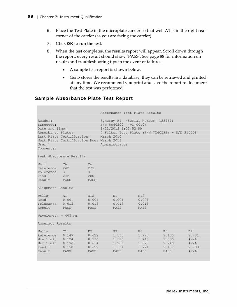
86 | Chapter 7: Instrument Qualification
6. Place the Test Plate in the microplate carrier so that well A1 is in the right rear corner of the carrier (as you are facing the carrier).
7. Click OK to run the test.
8. When the test completes, the results report will appear. Scroll down through the report; every result should show ‘PASS’. See page 88 for information on results and troubleshooting tips in the event of failures.
• A sample test report is shown below.
• Gen5 stores the results in a database; they can be retrieved and printed at any time. We recommend you print and save the report to document that the test was performed.
Sample Absorbance Plate Test Report
Absorbance Test Plate Results Reader: Synergy H1 (Serial Number: 122961) Basecode: P/N 8040200 (v1.00.0) Date and Time: 3/21/2012 1:03:52 PM Absorbance Plate: 7 Filter Test Plate (P/N 7260522) - S/N 210508 Last Plate Certification: March 2010 Next Plate Certification Due: March 2011 User: Administrator Comments: Peak Absorbance Results Well C6 C6 Reference 242 279 Tolerance 3 3 Read 242 280 Result PASS PASS Alignment Results Wells A1 A12 H1 H12 Read 0.001 0.001 0.001 0.001 Tolerance 0.015 0.015 0.015 0.015 Result PASS PASS PASS PASS Wavelength = 405 nm Accuracy Results Wells C1 E2 G3 H6 F5 D4 Reference 0.147 0.622 1.163 1.770 2.135 2.781 Min Limit 0.124 0.590 1.120 1.715 2.030 #N/A Max Limit 0.170 0.654 1.206 1.825 2.240 #N/A Read 1 0.150 0.622 1.164 1.771 2.137 2.783 Result PASS PASS PASS PASS PASS #N/A
BioTek Instruments, Inc.
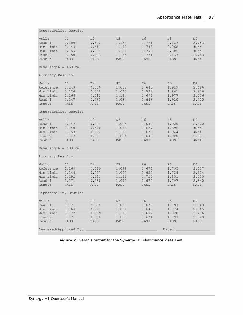
Absorbance Plate Test | 87
Repeatability Results Wells C1 E2 G3 H6 F5 D4 Read 1 0.150 0.622 1.164 1.771 2.137 2.783 Min Limit 0.143 0.611 1.147 1.748 2.068 #N/A Max Limit 0.156 0.634 1.180 1.794 2.206 #N/A Read 2 0.150 0.623 1.164 1.771 2.137 2.783 Result PASS PASS PASS PASS PASS #N/A Wavelength = 450 nm Accuracy Results Wells C1 E2 G3 H6 F5 D4 Reference 0.143 0.580 1.082 1.645 1.919 2.496 Min Limit 0.120 0.548 1.040 1.592 1.861 2.376 Max Limit 0.166 0.612 1.124 1.698 1.977 2.616 Read 1 0.147 0.581 1.084 1.648 1.920 2.500 Result PASS PASS PASS PASS PASS PASS Repeatability Results Wells C1 E2 G3 H6 F5 D4 Read 1 0.147 0.581 1.084 1.648 1.920 2.500 Min Limit 0.140 0.570 1.068 1.627 1.896 #N/A Max Limit 0.153 0.592 1.100 1.670 1.944 #N/A Read 2 0.147 0.581 1.084 1.648 1.920 2.501 Result PASS PASS PASS PASS PASS #N/A Wavelength = 630 nm Accuracy Results Wells C1 E2 G3 H6 F5 D4 Reference 0.169 0.589 1.099 1.673 1.795 2.337 Min Limit 0.146 0.557 1.057 1.620 1.739 2.224 Max Limit 0.192 0.621 1.141 1.726 1.851 2.450 Read 1 0.171 0.588 1.097 1.670 1.797 2.340 Result PASS PASS PASS PASS PASS PASS Repeatability Results Wells C1 E2 G3 H6 F5 D4 Read 1 0.171 0.588 1.097 1.670 1.797 2.340 Min Limit 0.164 0.577 1.081 1.649 1.774 2.265 Max Limit 0.177 0.599 1.113 1.692 1.820 2.416 Read 2 0.171 0.588 1.097 1.671 1.797 2.340 Result PASS PASS PASS PASS PASS PASS Reviewed/Approved By: _________________________________ Date: ________________
Figure 2: Sample output for the Synergy H1 Absorbance Plate Test.
Synergy H1 Operator’s Manual
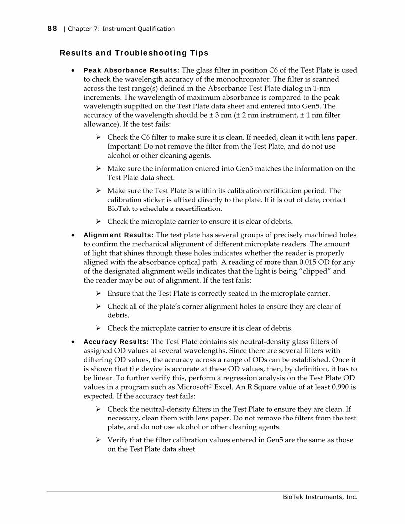
88 | Chapter 7: Instrument Qualification
Results and Troubleshooting Tips
• Peak Absorbance Results: The glass filter in position C6 of the Test Plate is used to check the wavelength accuracy of the monochromator. The filter is scanned across the test range(s) defined in the Absorbance Test Plate dialog in 1-nm increments. The wavelength of maximum absorbance is compared to the peak wavelength supplied on the Test Plate data sheet and entered into Gen5. The accuracy of the wavelength should be ± 3 nm (± 2 nm instrument, ± 1 nm filter allowance). If the test fails:
Check the C6 filter to make sure it is clean. If needed, clean it with lens paper. Important! Do not remove the filter from the Test Plate, and do not use alcohol or other cleaning agents.
Make sure the information entered into Gen5 matches the information on the Test Plate data sheet.
Make sure the Test Plate is within its calibration certification period. The calibration sticker is affixed directly to the plate. If it is out of date, contact BioTek to schedule a recertification.
Check the microplate carrier to ensure it is clear of debris.
• Alignment Results: The test plate has several groups of precisely machined holes to confirm the mechanical alignment of different microplate readers. The amount of light that shines through these holes indicates whether the reader is properly aligned with the absorbance optical path. A reading of more than 0.015 OD for any of the designated alignment wells indicates that the light is being “clipped” and the reader may be out of alignment. If the test fails:
Ensure that the Test Plate is correctly seated in the microplate carrier.
Check all of the plate’s corner alignment holes to ensure they are clear of debris.
Check the microplate carrier to ensure it is clear of debris.
• Accuracy Results: The Test Plate contains six neutral-density glass filters of assigned OD values at several wavelengths. Since there are several filters with differing OD values, the accuracy across a range of ODs can be established. Once it is shown that the device is accurate at these OD values, then, by definition, it has to be linear. To further verify this, perform a regression analysis on the Test Plate OD values in a program such as Microsoft® Excel. An R Square value of at least 0.990 is expected. If the accuracy test fails:
Check the neutral-density filters in the Test Plate to ensure they are clean. If necessary, clean them with lens paper. Do not remove the filters from the test plate, and do not use alcohol or other cleaning agents.
Verify that the filter calibration values entered in Gen5 are the same as those on the Test Plate data sheet.
BioTek Instruments, Inc.
Absorbance Liquid Tests | 89
Verify that the Test Plate is within its calibration certification period. The calibration sticker is affixed directly to the plate. If it is out of date, contact BioTek to schedule a recertification.
• Repeatability Results: This test ensures the instrument meets its repeatability specification by reading each neutral-density filter on the Test Plate twice with the filter in the same location. If the test fails:
Check the neutral-density filters on the Test Plate to ensure there is no debris that may have shifted between readings and caused changes.
Check the microplate carrier to ensure it is clear of debris.
Absorbance Liquid Tests
Applies only to models with Absorbance capabilities. Conducting Liquid Tests confirms the reader’s ability to perform to specification with liquid samples. Liquid testing differs from testing with the Absorbance Test Plate in that liquid in the wells has a meniscus, whereas the Test Plate’s neutral density glass filters do not. The optics characteristics may differ in these two cases, thus alerting the operator to different types of problems.
Absorbance Liquid Test 1
Absorbance Liquid Test 1 confirms repeatability and alignment of the reader when a solution is used in the microplate. If these tests pass, then the lens placement and optical system cleanliness are proven.
Materials
Manufacturer part numbers are subject to change.
• New 96-well, clear, flat-bottom microplate (Corning Costar #3590 recommended)
• Stock Solution A or B, which may be formulated by diluting a dye solution available from BioTek (A) or from the ingredients listed below (B).
Solution A
• BioTek QC Check Solution No. 1 (PN 7120779, 25 mL; PN 7120782, 125 mL)
• Deionized water
• 5-mL Class A volumetric pipette
• 100-mL volumetric flask
1. Pipette a 5-mL aliquot of BioTek QC Check Solution No. 1 into a 100-mL volumetric flask.
Synergy H1 Operator’s Manual
90 | Chapter 7: Instrument Qualification
2. Add 95 mL of DI water; cap and shake well. The solution should measure approximately 2.000 OD when using 200 µL in a flat-bottom microwell.
Solution B
• Deionized water
• FD&C Yellow No. 5 dye powder (typically 90% pure)
• Tween 20 (polyoxyethylene (20) sorbitan monolaurate) or BioTek wetting agent (PN 7773002) (a 10% Tween solution)
• Precision balance with capacity of 100 g minimum and readability of 0.001 g
• Weigh boat
• 1-liter volumetric flask
1. Weigh out 0.092 g of FD&C Yellow No. 5 dye powder into a weigh boat.
2. Rinse the contents into a 1-liter volumetric flask.
3. Add 0.5 mL of Tween 20, or 5 mL of BioTek’s wetting agent.
4. Fill to 1 liter with DI water; cap and shake well. The solution should measure approximately 2.000 OD when using 200 µL in a flat-bottom microwell.
Prepare the Plate
Be sure to use a new microplate, because fingerprints or scratches may cause variations in readings.
1. Using freshly prepared stock solution (Solution A or B), prepare a 1:2 dilution using deionized water (one part stock, one part deionized water; the resulting solution is a 1:2 dilution).
2. Pipette 200 μL of the concentrated solution (A or B) into the first column of wells in the microplate.
3. Pipette 200 µL of the diluted solution into the second column of wells.
After pipetting the diluted test solution into the microplate and before reading the plate, we strongly recommend shaking the plate for four minutes. This will allow any air bubbles in the solution to settle and the meniscus to stabilize. Alternatively, wait 20 minutes after pipetting the test solution before reading the plate.
BioTek Instruments, Inc.
Absorbance Liquid Tests | 91
Read the Plate
1. Using Gen5, read the microplate five times at 405 nm using the Normal read mode, single wavelength, no blanking. Save the data after each read (“Normal” plate position).
2. Without delay, rotate the microplate 180 degrees so that well A1 is in the “H12” position. Read the plate five more times, saving the data after each read (“Turnaround” plate position).
3. Print out the ten sets of raw data, or export them to an Excel spreadsheet.
Analyze the Results
1. The plate is read five times in the “Normal” position at 405 nm. Calculate the Mean OD and Standard Deviation of those five reads for each well in columns 1 and 2.
2. For each well in columns 1 and 2, calculate the Allowed Deviation using the repeatability specification for a 96-well plate: ± 1% ± 0.005 OD from 0.000 to 2.000 OD (Mean * 0.010 + 0.005). For each well, its standard deviation should be less than its allowed deviation.
Example: Five readings in well A1 of 0.802, 0.802, 0.799, 0.798, and 0.801 result in a mean of 0.8004 and a standard deviation of 0.0018. The mean multiplied by 1.0% (0.8004 * 0.010) equals 0.008, and when added to 0.005 equals 0.013; this is the allowed deviation for well A1. Since the standard deviation for well A1 is less than 0.013, the well meets the test criteria.
3. The plate is read five times in the “Turnaround” position at 405 nm. Calculate the Mean OD of those reads for each well in columns 11 and 12.
4. Perform a mathematical comparison of the Mean values for each microwell in its Normal and Turnaround positions (that is, compare A1 to H12, A2 to H11, B1 to G12,… H2 to A11). To pass the test, the differences in the compared mean values must be within the accuracy specification for a 96-well microplate: ± 1.0% ± 0.010 OD from 0.000 to 2.000 OD.
Example: If the mean value for well A1 in the Normal position is 1.902 with a specified accuracy of ± 1.0% ± 0.010 OD, then the expected range for the mean of the well in its Turnaround (H12) position is 1.873 to 1.931 OD. 1.902 x 0.010 + 0.010 = 0.029; 1.902 - 0.029 = 1.873; 1.902 + 0.029 = 1.931.
Repeatability Specification:
± 1.0% ± 0.005 OD from 0.000 to 2.000 OD
± 3.0% ± 0.005 OD from 2.000 OD to 2.500 OD
Accuracy Specification:
± 1.0% ± 0.010 OD from 0.000 to 2.000 OD
± 3.0% ± 0.010 OD from 2.000 OD to 2.500 OD
Synergy H1 Operator’s Manual
92 | Chapter 7: Instrument Qualification
Absorbance Liquid Test 2
The recommended method for testing the instrument’s alignment, repeatability, and accuracy is to use the Absorbance Test Plate (see page 83). If the Test Plate is not available, however, Liquid Test 2 can be used for these tests.
Materials
• A new 96-well, clear, flat-bottom microplate (Corning Costar #3590 is recommended)
• Ten test tubes, numbered consecutively, set up in a rack
• Calibrated hand pipette (Class A volumetric pipette recommended)
• Solution A or B (see the instructions for Liquid Test 1)
• A 0.05% solution of deionized water and Tween 20
Prepare the Dilutions
Create a percentage dilution series, beginning with 100% of the original concentrated stock solution (A or B) in the first tube, 90% of the original solution in the second tube, 80% in the third tube, all the way to 10% in the tenth tube. Dilute using the 0.05% solution of deionized water and Tween 20. This solution can also be made by diluting the BioTek wetting agent 200:1.
Tube Number: 1 2 3 4 5 6 7 8 9 10
Volume of Original Concentrated Solution (mL)
20 18 16 14 12 10 8 6 4 2
Volume of 0.05% Tween Solution (mL)
0 2 4 6 8 10 12 14 16 18
Absorbance expected if original solution is 2.0 at 200 μL
2.0 1.8 1.6 1.4 1.2 1.0 0.8 0.6 0.4 0.2
The choice of dilutions and the absorbance of the original solution can be varied. Use this table as a model for calculating the expected absorbances of a series of dilutions, given a different absorbance of the original solution.
Prepare the Plate
• Pipette 200 µL of the concentrated solution from Tube 1 into each well of the first column, A1 to H1, of a new flat-bottom microplate.
• Pipette 200 µL from each of the remaining tubes into the wells of the corresponding column of the microplate (Tube 2 into wells A2 to H2, Tube 3 into wells A3 to H3, and so on).
BioTek Instruments, Inc.
Absorbance Liquid Tests | 93
Linearity and Repeatability Tests
1. Using Gen5, read the microplate prepared above five times using Normal mode, dual wavelength at 450/630 nm. Save the data after each read.
Do not discard the plate; you will use it for the Alignment test.
2. Print out the five sets of Delta OD data, or export them to an Excel spreadsheet.
3. Calculate the results for Linearity:
• Calculate the mean absorbance for each well, and average the means for each concentration.
• Perform a regression analysis on the data to determine if there is adequate linearity.
Since it is somewhat difficult to achieve high pipetting accuracy when conducting linear dilutions, an R Square value of at least 0.99 is considered adequate.
4. Calculate the results for Repeatability:
• Calculate the mean and standard deviation for the five readings taken in Step 1 at each concentration. Only one row of data needs to be analyzed.
• For each mean below 2.000 OD, calculate the allowed deviation using the repeatability specification for a 96-well plate of ± 1.0% ± 0.005 OD. If above 2.000 OD, apply the ± 3.0% ± 0.005 specification.
• The standard deviation for each set of readings should be less than the allowed deviation.
Example: Absorbance readings of 1.950, 1.948, 1.955, 1.952, and 1.950 will result in a mean of 1.951, and a standard deviation of 0.0026. The mean (1.951) multiplied by 1.0% (1.951 x 0.010) = 0.0195, which, when added to the 0.005 (0.0195 + 0.005) = 0.0245 OD, which is the allowed deviation. Since the standard deviation is less than this value, the reader meets the test criteria.
Repeatability Specification:
± 1.0% ± 0.005 OD from 0.000 to 2.000 OD
± 3.0% ± 0.005 OD from 2.000 OD to 2.500 OD
Alignment Test
1. Using the plate prepared for the Linearity Test on the previous page, conduct a Turnaround test by reading the plate five times with the A1 well in the H12 position. Save the data after each read.
Synergy H1 Operator’s Manual
94 | Chapter 7: Instrument Qualification
This test results in values for the four corner wells that can be used to determine alignment.
2. Calculate the means of the wells A1 and H1 in the Normal plate position (data from Linearity Test) and in the Turnaround position (from Step 1).
3. Compare the mean reading for well A1 to its mean reading when in the H12 position. Next, compare the mean values for the H1 well to the same well in the A12 position. The difference in the values for any two corresponding wells should be within the accuracy specification for the instrument.
Example: If the mean of well A1 in the normal position is 1.902, where the specified accuracy is ± 1.0% ± 0.010 OD, then the expected range for the mean of the same well in the H12 position is 1.873 to 1.931 OD. (1.902 x 1.0% = 0.019 + 0.010 = 0.029, which is added to and subtracted from 1.902 for the range.)
If the four corner wells are within the accuracy range, the reader is in alignment.
Accuracy Specification:
± 1.0% ± 0.010 OD from 0.000 to 2.000 OD
± 3.0% ± 0.010 OD from 2.000 OD to 2.500 OD
Absorbance Liquid Test 3 (optional)
This test verifies operation of the reader at 340 nm, and is provided for sites requiring proof of linearity at wavelengths lower than those attainable with the Absorbance Test Plate. This test is optional because the reader has good “front end” linearity throughout its wavelength range.
Materials
Manufacturer part numbers are subject to change.
• New 96-well, clear, flat-bottom microplate (Corning Costar #3590 recommended)
• Calibrated hand pipette(s)
• Beakers and graduated cylinder
• Precision balance with readability to 0.01 g
• Buffer solution described below
Buffer Solution
• Deionized water
• Phosphate-Buffered Saline (PBS), pH 7.2–7.6, Sigma tablets, #P4417 (or equivalent)
BioTek Instruments, Inc.
Absorbance Liquid Tests | 95
• β-NADH Powder (β-Nicotinamide Adenine Dinucleotide, Reduced Form) Sigma bulk catalog number N 8129, or preweighed 10-mg vials, Sigma number N6785-10VL (or BioTek PN 98233). Store the powder according to the guidelines on its packaging.
1. Prepare a PBS solution from the Sigma tablets.
2. In a beaker, mix 50 mL of the PBS solution with 10 mg of the β-NADH powder and mix thoroughly. This is the 100% Test Solution.
3. (Optional) Read a 150-µL sample of the solution at 340 nm; it should be within 0.700 to 1.000 OD. If low, adjust up by adding more powder. Do not adjust if slightly high.
Prepare the Plate
1. Prepare the 75% Test Solution by mixing 15 mL of the 100% Test Solution with 5 mL of the PBS Solution.
2. Prepare the 50% Test Solution by mixing 10 mL of the 100% Test Solution with 10 mL of the PBS Solution.
3. Carefully pipette the three solutions into a new 96-well microplate:
• 150 µL of the 100% Test Solution into all wells of columns 1 and 2
• 150 µL of the 75% Test Solution into all wells of columns 3 and 4
• 150 µL of the 50% Test Solution into all wells of column 5 and 6
Read the Plate
1. Using Gen5, read the microplate five times using Normal mode, single wavelength at 340 nm, no blanking. Save the data after each read.
2. Print out the five sets of raw data, or export them to an Excel spreadsheet.
Analyze the Results
1. For each well, calculate the Mean OD and Standard Deviation of the five readings.
2. For each mean calculated in step 1, calculate the allowed deviation using the repeatability specification for a 96-well plate: ± 1% ± 0.005 OD from 0.000 to 2.000 OD (Mean x 0.010 + 0.005). For each well, its standard deviation should be less than its allowed deviation.
Example: Five readings in well A1 of 0.802, 0.802, 0.799, 0.798, and 0.801 result in a mean of 0.8004 and a standard deviation of 0.0018. The mean multiplied by 1.0% (0.8004 * 0.010) equals 0.008, and when added to 0.005 equals 0.013; this is the allowed deviation for well A1. Since the standard deviation for well A1 is less than 0.013, the well meets the test criteria.
Synergy H1 Operator’s Manual
96 | Chapter 7: Instrument Qualification
3. Calculate the results for Linearity:
• For each of the three Test Solutions, calculate the average Mean OD for the wells containing that solution (mean of wells A1 to H2, A3 to H4, and A5 to H6).
• Perform a regression analysis on the data to determine if there is adequate linearity. The three average Mean OD values are the “Y” values. The solution concentrations are the “X” values (1.00, 0.75, 0.50).
Since it is somewhat difficult to achieve high pipetting accuracy when conducting linear dilutions, an R Square value of at least 0.99 is considered adequate.
Repeatability Specification:
± 1.0% ± 0.005 OD from 0.000 to 2.000 OD
± 3.0% ± 0.005 OD from 2.000 OD to 2.500 OD
BioTek Instruments, Inc.
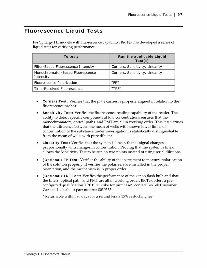
Fluorescence Liquid Tests | 97
Fluorescence Liquid Tests
For Synergy H1 models with fluorescence capability, BioTek has developed a series of liquid tests for verifying performance.
To test: Run the applicable Liquid Test(s)
Filter-Based Fluorescence Intensity Corners, Sensitivity, Linearity
Monochromator-Based Fluorescence Intensity
Corners, Sensitivity, Linearity
Fluorescence Polarization “FP”
Time-Resolved Fluorescence “TRF”
• Corners Test: Verifies that the plate carrier is properly aligned in relation to the fluorescence probes.
• Sensitivity Test: Verifies the fluorescence reading capability of the reader. The ability to detect specific compounds at low concentrations ensures that the monochromators, optical paths, and PMT are all in working order. This test verifies that the difference between the mean of wells with known lower limits of concentration of the substance under investigation is statistically distinguishable from the mean of wells with pure diluent.
• Linearity Test: Verifies that the system is linear, that is, signal changes proportionally with changes in concentration. Proving that the system is linear allows the Sensitivity Test to be run on two points instead of using serial dilutions.
• (Optional) FP Test: Verifies the ability of the instrument to measure polarization of the solution properly. It verifies the polarizers are installed in the proper orientation, and the mechanism is in proper order.
• (Optional) TRF Test: Verifies the performance of the xenon flash bulb and that the filters, optical path, and PMT are all in working order. BioTek offers a pre-configured qualification TRF filter cube for purchase*; contact BioTek Customer Care and ask about part number 8030555.
* Returnable within 90 days for a refund less a 15% restocking fee.
Synergy H1 Operator’s Manual
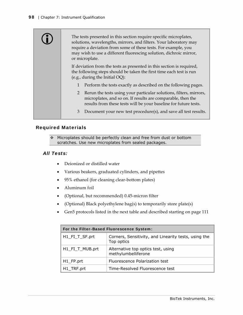
98 | Chapter 7: Instrument Qualification
The tests presented in this section require specific microplates, solutions, wavelengths, mirrors, and filters. Your laboratory may require a deviation from some of these tests. For example, you may wish to use a different fluorescing solution, dichroic mirror, or microplate.
If deviation from the tests as presented in this section is required, the following steps should be taken the first time each test is run (e.g., during the Initial OQ):
1 Perform the tests exactly as described on the following pages.
2 Rerun the tests using your particular solutions, filters, mirrors, microplates, and so on. If results are comparable, then the results from these tests will be your baseline for future tests.
3 Document your new test procedure(s), and save all test results.
Required Materials
Microplates should be perfectly clean and free from dust or bottom scratches. Use new microplates from sealed packages.
All Tests:
• Deionized or distilled water
• Various beakers, graduated cylinders, and pipettes
• 95% ethanol (for cleaning clear-bottom plates)
• Aluminum foil
• (Optional, but recommended) 0.45-micron filter
• (Optional) Black polyethylene bag(s) to temporarily store plate(s)
• Gen5 protocols listed in the next table and described starting on page 111
For the Filter-Based Fluorescence System:
H1_FI_T_SF.prt Corners, Sensitivity, and Linearity tests, using the Top optics
H1_FI_T_MUB.prt Alternative top optics test, using methylumbelliferone
H1_FP.prt Fluorescence Polarization test
H1_TRF.prt Time-Resolved Fluorescence test
BioTek Instruments, Inc.
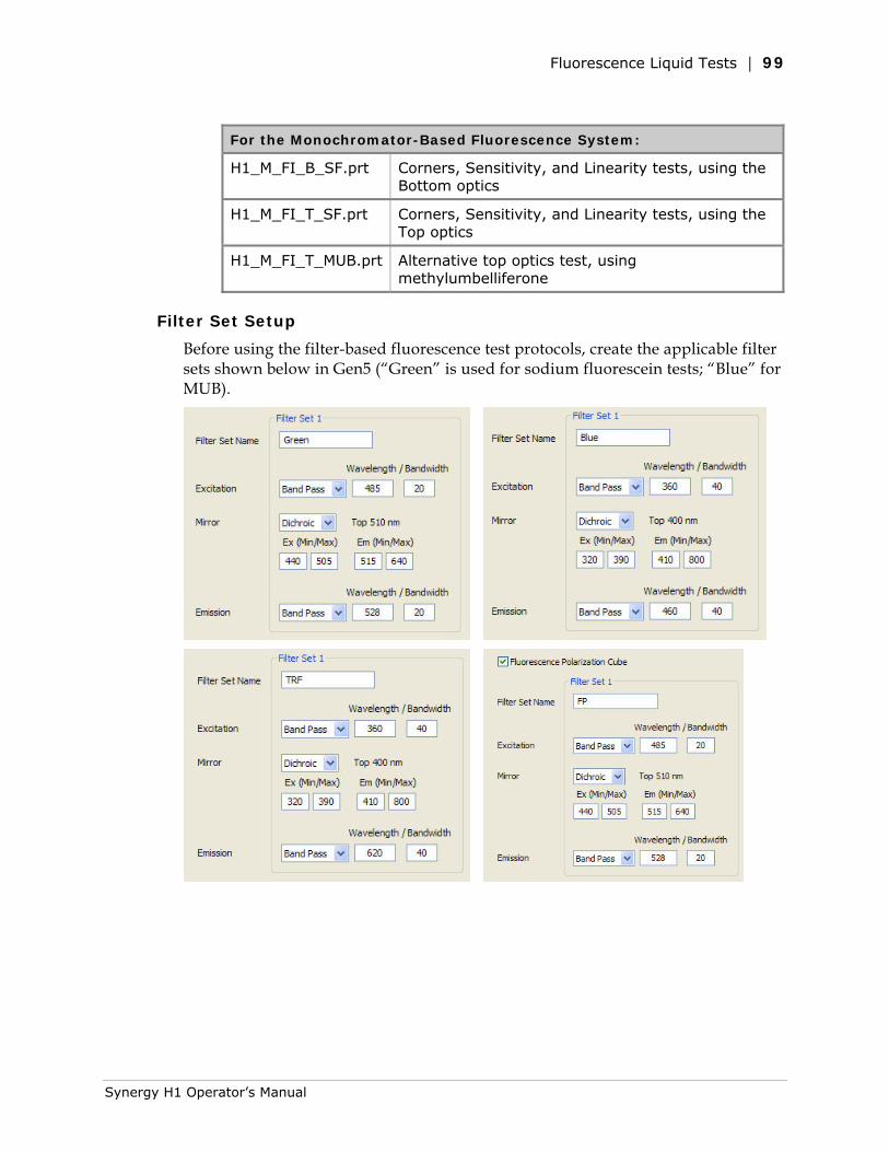
Fluorescence Liquid Tests | 99
For the Monochromator-Based Fluorescence System:
H1_M_FI_B_SF.prt Corners, Sensitivity, and Linearity tests, using the Bottom optics
H1_M_FI_T_SF.prt Corners, Sensitivity, and Linearity tests, using the Top optics
H1_M_FI_T_MUB.prt Alternative top optics test, using methylumbelliferone
Filter Set Setup
Before using the filter-based fluorescence test protocols, create the applicable filter sets shown below in Gen5 (“Green” is used for sodium fluorescein tests; “Blue” for MUB).
Synergy H1 Operator’s Manual
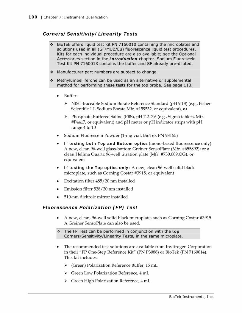
100 | Chapter 7: Instrument Qualification
Corners/Sensitivity/Linearity Tests
BioTek offers liquid test kit PN 7160010 containing the microplates and solutions used in all (SF/MUB/Eu) fluorescence liquid test procedures. Kits for each individual procedure are also available; see the Optional Accessories section in the Introduction chapter. Sodium Fluorescein Test Kit PN 7160013 contains the buffer and SF already pre-diluted.
Manufacturer part numbers are subject to change.
Methylumbelliferone can be used as an alternative or supplemental method for performing these tests for the top probe. See page 113.
• Buffer:
NIST-traceable Sodium Borate Reference Standard (pH 9.18) (e.g., Fisher-Scientific 1 L Sodium Borate Mfr. #159532, or equivalent), or
Phosphate-Buffered Saline (PBS), pH 7.2–7.6 (e.g., Sigma tablets, Mfr. #P4417, or equivalent) and pH meter or pH indicator strips with pH range 4 to 10
• Sodium Fluorescein Powder (1-mg vial, BioTek PN 98155)
• If testing both Top and Bottom optics (mono-based fluorescence only): A new, clean 96-well glass-bottom Greiner SensoPlate (Mfr. #655892); or a clean Hellma Quartz 96-well titration plate (Mfr. #730.009.QG); or equivalent
• If testing the Top optics only: A new, clean 96-well solid black microplate, such as Corning Costar #3915, or equivalent
• Excitation filter 485/20 nm installed
• Emission filter 528/20 nm installed
• 510-nm dichroic mirror installed
Fluorescence Polarization (FP) Test
• A new, clean, 96-well solid black microplate, such as Corning Costar #3915. A Greiner SensoPlate can also be used.
The FP Test can be performed in conjunction with the top Corners/Sensitivity/Linearity Tests, in the same microplate.
• The recommended test solutions are available from Invitrogen Corporation in their “FP One-Step Reference Kit” (PN P3088) or BioTek (PN 7160014). This kit includes:
(Green) Polarization Reference Buffer, 15 mL
Green Low Polarization Reference, 4 mL
Green High Polarization Reference, 4 mL
BioTek Instruments, Inc.
Fluorescence Liquid Tests | 101
The kit also includes two red polarization solutions, not used.
• Excitation filter 485/20 nm and emission filter 528/20 nm installed
• 510-nm dichroic mirror and polarizers installed
Time-Resolved Fluorescence (TRF) Test
BioTek offers a pre-configured qualification TRF filter cube for purchase; see page 97.
• 15-mL conical-bottom, polypropylene sample tube
• Excitation filter 360/40 nm and emission filter 620/40 nm installed
• 400-nm dichroic mirror installed
• A new, clean 96-well solid white microplate, such as Corning Costar #3912
• The recommended test solution (FluoSpheres carboxylate-modified microspheres, 0.2 µm europium luminescent, 2 μL) is available from Invitrogen Corporation (PN F20881) or BioTek (PN 7160011)
Test Solutions
Corners/Sensitivity/Linearity Tests
If using BioTek’s sodium fluorescein powder (PN 98155), be sure to hold the vial upright and open it carefully; the material may be concentrated at the top. If a centrifuge is available, spin down the tube before opening.
When diluting the sodium fluorescein powder in buffer, it takes time for the powder to completely dissolve. Allow the solution to dissolve for five minutes, with intermittent vortexing, before preparing the titration dyes.
Wrap the vial containing the stock solution in foil to prevent exposure to light. Discard unused solution after seven days. Discard any open, unused buffer solution after seven days.
1. The Sodium Borate solution does not require further preparation; proceed
to step 2. If you are using PBS, prepare the solution:
• (Optional, but recommended) Using a 0.45-micron filter, filter 200 mL of deionized or distilled water.
• Follow the manufacturer’s instructions on the PBS packaging to create 200 mL, dissolving the necessary amount of PBS into the filtered water.
Synergy H1 Operator’s Manual
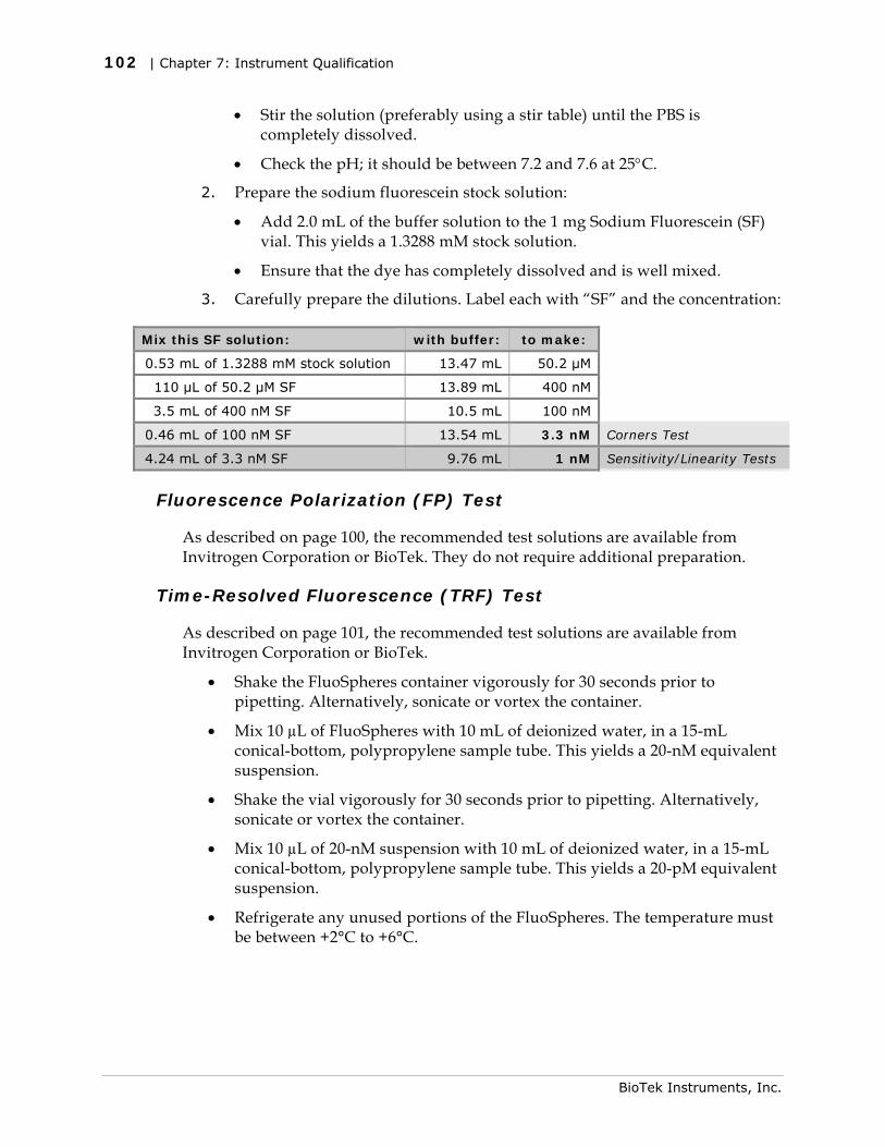
102 | Chapter 7: Instrument Qualification
• Stir the solution (preferably using a stir table) until the PBS is completely dissolved.
• Check the pH; it should be between 7.2 and 7.6 at 25°C.
2. Prepare the sodium fluorescein stock solution:
• Add 2.0 mL of the buffer solution to the 1 mg Sodium Fluorescein (SF) vial. This yields a 1.3288 mM stock solution.
• Ensure that the dye has completely dissolved and is well mixed.
3. Carefully prepare the dilutions. Label each with “SF” and the concentration:
Mix this SF solution: with buffer: to make:
0.53 mL of 1.3288 mM stock solution 13.47 mL 50.2 μM
110 µL of 50.2 μM SF 13.89 mL 400 nM
3.5 mL of 400 nM SF 10.5 mL 100 nM
0.46 mL of 100 nM SF 13.54 mL 3.3 nM Corners Test
4.24 mL of 3.3 nM SF 9.76 mL 1 nM Sensitivity/Linearity Tests
Fluorescence Polarization (FP) Test
As described on page 100, the recommended test solutions are available from Invitrogen Corporation or BioTek. They do not require additional preparation.
Time-Resolved Fluorescence (TRF) Test
As described on page 101, the recommended test solutions are available from Invitrogen Corporation or BioTek.
• Shake the FluoSpheres container vigorously for 30 seconds prior to pipetting. Alternatively, sonicate or vortex the container.
• Mix 10 µL of FluoSpheres with 10 mL of deionized water, in a 15-mL conical-bottom, polypropylene sample tube. This yields a 20-nM equivalent suspension.
• Shake the vial vigorously for 30 seconds prior to pipetting. Alternatively, sonicate or vortex the container.
• Mix 10 µL of 20-nM suspension with 10 mL of deionized water, in a 15-mL conical-bottom, polypropylene sample tube. This yields a 20-pM equivalent suspension.
• Refrigerate any unused portions of the FluoSpheres. The temperature must be between +2°C to +6°C.
BioTek Instruments, Inc.
Fluorescence Liquid Tests | 103
The prepared TRF plate can be kept for a maximum of seven days, if covered and stored in the dark between +2°C to +6°C.
Allow the plate to sit at room temperature for approximately 15 minutes prior to use.
Shake the plate gently prior to the read.
Procedure
1. If you have not already done so, create the Gen5 protocols as described starting on page 111.
2. If you have not already done so, prepare the solutions for the tests you plan to perform. See page 101.
Refer to Pipette Maps on page 104 for the remaining steps.
3. Perform the Corners/Sensitivity/Linearity tests using the Top optics of the filter-based fluorescence system:
• Pipette the solutions for the Corners, Sensitivity, and Linearity Tests into a clean 96-well quartz or glass-bottom microplate.
• Create an experiment based on the H1_FI_T_SF.prt protocol. Read the plate and then save the experiment.
4. If your reader is equipped with Fluorescence Polarization capability:
• Pipette the solutions for the “FP” test into the same plate used in step 3.
• Create an experiment based on the H1_FP.prt protocol. Read the plate and then save the experiment.
5. If your reader is equipped with the monochromator-based fluorescence system, perform the Corners/Sensitivity/Linearity tests for that system:
• Using the same plate as was used in step 4, pipette 50 µL/well of buffer into wells C1–F5 and C10–F12.
• Create experiments based on the H1_M_FI_B_SF.prt (for bottom optics) and H1_FI_T_SF.prt (for top optics) protocols. Read the plate and then save the experiments.
6. If your reader is equipped with Time-Resolved Fluorescence capability:
• Pipette the solutions for the “TRF” test into a new 96-well solid white plate.
• Create an experiment based on the H1_TRF.prt protocol. Read the plate and then save the experiment.
7. Calculate and evaluate results as described under Results Analysis, starting on page 107.
Synergy H1 Operator’s Manual
104 | Chapter 7: Instrument Qualification
Pipette Maps
Seal the plates with foil or store them in black polyethylene bags until use. When using a clear-bottom plate, if the base of the plate is touched, clean the entire base with alcohol (95% ethanol) and then wipe with a lint-free cloth. Before placing the plate in the instrument, blow the bottom of the plate with an aerosol duster.
The Corners, Sensitivity, Linearity, and “FP” pipette maps are designed so that multiple tests can be run using the same microplate. Some examples:
• Corners, Sensitivity, and Linearity tests for the bottom optics can be performed using the same quartz or glass-bottom plate.
• Corners/Sensitivity/Linearity (top optics) and the FP test can be performed using the same solid black plate.
• Corners/Sensitivity/Linearity (top optics) for the filter- and monochromator-based fluorescence systems can be performed using the same solid black plate.
Corners Test
You can omit the buffer when using a solid black plate or the Greiner SensoPlate.
• Pipette 200 µL of the 3.3 nM SF solution into the “corner” wells.
• Pipette 200 µL of the buffer in the wells surrounding the SF.
Sensitivity and Linearity Tests
Use an eight-channel pipette with just four tips installed. Perform these instructions carefully, and refer to the plate map.
• Pipette 150 µL of the buffer into columns 2–5 and 10–12. Discard the tips.
• Pipette 150 µL of the 1 nM SF solution into column 1.
• Pipette 150 µL of the 1 nm SF solution into column 2. Mix the wells using the pipette. Do not discard the tips.
• Aspirate 150 µL from column 2 and dispense into column 3. Mix the wells using the pipette. Do not discard the tips.
• Aspirate 150 µL from column 3 and dispense into column 4. Mix the wells using the pipette. Do not discard the tips.
BioTek Instruments, Inc.
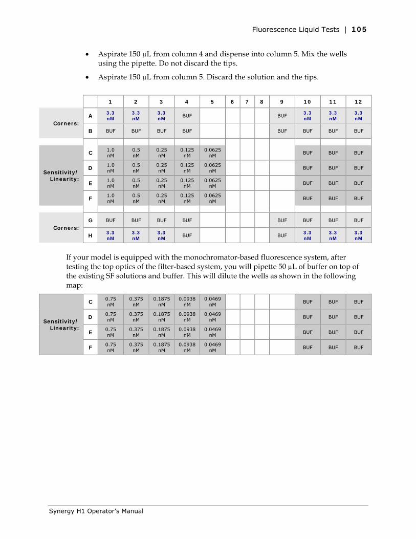
Fluorescence Liquid Tests | 105
• Aspirate 150 µL from column 4 and dispense into column 5. Mix the wells using the pipette. Do not discard the tips.
• Aspirate 150 µL from column 5. Discard the solution and the tips.
1 2 3 4 5 6 7 8 9 10 11 12
Corners: A 3.3
nM 3.3 nM
3.3 nM
BUF BUF 3.3 nM
3.3 nM
3.3 nM
B BUF BUF BUF BUF BUF BUF BUF BUF
Sensitivity/Linearity:
C 1.0 nM
0.5 nM
0.25 nM
0.125 nM
0.0625 nM
BUF BUF BUF
D 1.0 nM
0.5 nM
0.25 nM
0.125 nM
0.0625 nM
BUF BUF BUF
E 1.0 nM
0.5 nM
0.25 nM
0.125 nM
0.0625 nM
BUF BUF BUF
F 1.0 nM
0.5 nM
0.25 nM
0.125 nM
0.0625 nM
BUF BUF BUF
Corners: G BUF BUF BUF BUF BUF BUF BUF BUF
H 3.3 nM
3.3 nM
3.3 nM
BUF BUF 3.3 nM
3.3 nM
3.3 nM
If your model is equipped with the monochromator-based fluorescence system, after testing the top optics of the filter-based system, you will pipette 50 µL of buffer on top of the existing SF solutions and buffer. This will dilute the wells as shown in the following map:
Sensitivity/Linearity:
C 0.75 nM
0.375 nM
0.1875 nM
0.0938 nM
0.0469 nM
BUF BUF BUF
D 0.75 nM
0.375 nM
0.1875 nM
0.0938 nM
0.0469 nM
BUF BUF BUF
E 0.75 nM
0.375 nM
0.1875 nM
0.0938 nM
0.0469 nM
BUF BUF BUF
F 0.75 nM
0.375 nM
0.1875 nM
0.0938 nM
0.0469 nM
BUF BUF BUF
Synergy H1 Operator’s Manual
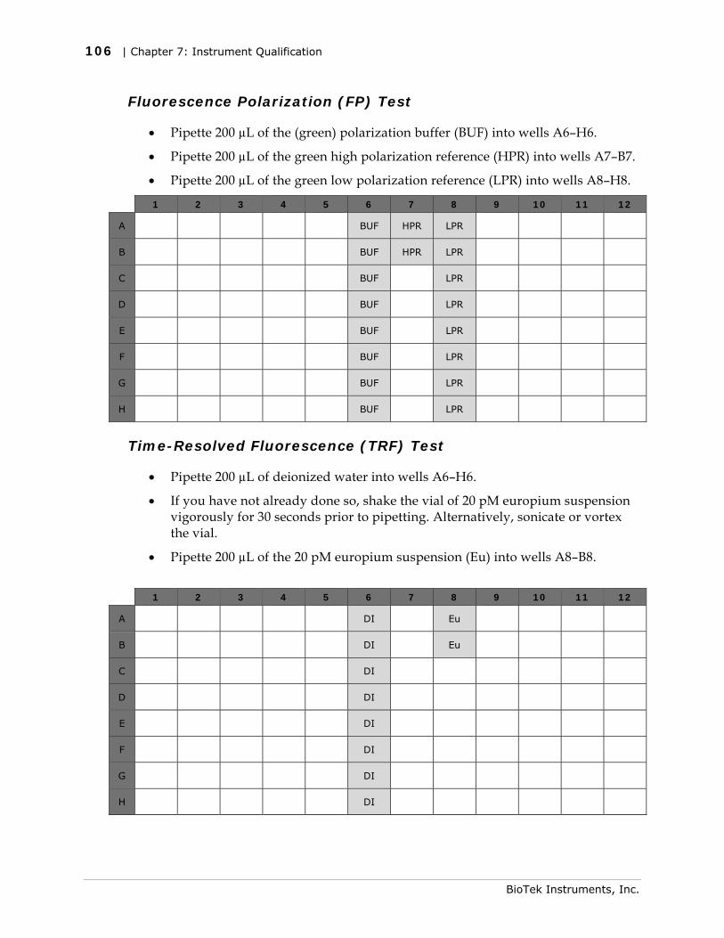
106 | Chapter 7: Instrument Qualification
Fluorescence Polarization (FP) Test
• Pipette 200 µL of the (green) polarization buffer (BUF) into wells A6–H6.
• Pipette 200 µL of the green high polarization reference (HPR) into wells A7–B7.
• Pipette 200 µL of the green low polarization reference (LPR) into wells A8–H8.
1 2 3 4 5 6 7 8 9 10 11 12
A BUF HPR LPR
B BUF HPR LPR
C BUF LPR
D BUF LPR
E BUF LPR
F BUF LPR
G BUF LPR
H BUF LPR
Time-Resolved Fluorescence (TRF) Test
• Pipette 200 µL of deionized water into wells A6–H6.
• If you have not already done so, shake the vial of 20 pM europium suspension vigorously for 30 seconds prior to pipetting. Alternatively, sonicate or vortex the vial.
• Pipette 200 µL of the 20 pM europium suspension (Eu) into wells A8–B8.
1 2 3 4 5 6 7 8 9 10 11 12
A DI Eu
B DI Eu
C DI
D DI
E DI
F DI
G DI
H DI
BioTek Instruments, Inc.
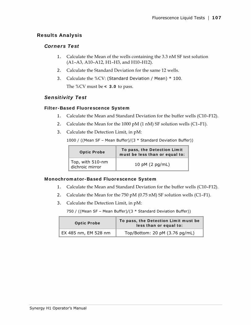
Fluorescence Liquid Tests | 107
Results Analysis
Corners Test
1. Calculate the Mean of the wells containing the 3.3 nM SF test solution (A1–A3, A10–A12, H1–H3, and H10–H12).
2. Calculate the Standard Deviation for the same 12 wells.
3. Calculate the %CV: (Standard Deviation / Mean) * 100.
The %CV must be < 3.0 to pass.
Sensitivity Test
Filter-Based Fluorescence System
1. Calculate the Mean and Standard Deviation for the buffer wells (C10–F12).
2. Calculate the Mean for the 1000 pM (1 nM) SF solution wells (C1–F1).
3. Calculate the Detection Limit, in pM:
1000 / ((Mean SF – Mean Buffer)/(3 * Standard Deviation Buffer))
Optic Probe To pass, the Detection Limit
must be less than or equal to:
Top, with 510-nm dichroic mirror
10 pM (2 pg/mL)
Monochromator-Based Fluorescence System
1. Calculate the Mean and Standard Deviation for the buffer wells (C10–F12).
2. Calculate the Mean for the 750 pM (0.75 nM) SF solution wells (C1–F1).
3. Calculate the Detection Limit, in pM:
750 / ((Mean SF – Mean Buffer)/(3 * Standard Deviation Buffer))
Optic Probe To pass, the Detection Limit must be
less than or equal to:
EX 485 nm, EM 528 nm Top/Bottom: 20 pM (3.76 pg/mL)
Synergy H1 Operator’s Manual
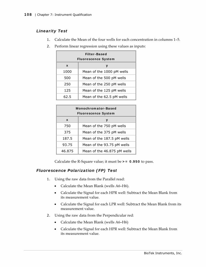
108 | Chapter 7: Instrument Qualification
Linearity Test
1. Calculate the Mean of the four wells for each concentration in columns 1–5.
2. Perform linear regression using these values as inputs:
Filter-Based
Fluorescence System
x y
1000 Mean of the 1000 pM wells
500 Mean of the 500 pM wells
250 Mean of the 250 pM wells
125 Mean of the 125 pM wells
62.5 Mean of the 62.5 pM wells
Monochromator-Based
Fluorescence System
x y
750 Mean of the 750 pM wells
375 Mean of the 375 pM wells
187.5 Mean of the 187.5 pM wells
93.75 Mean of the 93.75 pM wells
46.875 Mean of the 46.875 pM wells
3. Calculate the R-Square value; it must be >= 0.950 to pass.
Fluorescence Polarization (FP) Test
1. Using the raw data from the Parallel read:
• Calculate the Mean Blank (wells A6–H6).
• Calculate the Signal for each HPR well: Subtract the Mean Blank from its measurement value.
• Calculate the Signal for each LPR well: Subtract the Mean Blank from its measurement value.
2. Using the raw data from the Perpendicular red:
• Calculate the Mean Blank (wells A6–H6)
• Calculate the Signal for each HPR well: Subtract the Mean Blank from its measurement value.
BioTek Instruments, Inc.
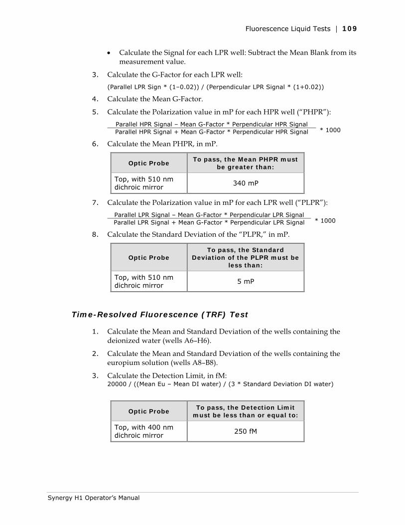
Fluorescence Liquid Tests | 109
• Calculate the Signal for each LPR well: Subtract the Mean Blank from its measurement value.
3. Calculate the G-Factor for each LPR well: (Parallel LPR Sign * (1–0.02)) / (Perpendicular LPR Signal * (1+0.02))
4. Calculate the Mean G-Factor.
5. Calculate the Polarization value in mP for each HPR well (“PHPR”): Parallel HPR Signal – Mean G-Factor * Perpendicular HPR Signal
* 1000 Parallel HPR Signal + Mean G-Factor * Perpendicular HPR Signal
6. Calculate the Mean PHPR, in mP.
Optic Probe To pass, the Mean PHPR must
be greater than:
Top, with 510 nm dichroic mirror
340 mP
7. Calculate the Polarization value in mP for each LPR well (“PLPR”): Parallel LPR Signal – Mean G-Factor * Perpendicular LPR Signal
* 1000 Parallel LPR Signal + Mean G-Factor * Perpendicular LPR Signal
8. Calculate the Standard Deviation of the “PLPR,” in mP.
Optic Probe To pass, the Standard
Deviation of the PLPR must be less than:
Top, with 510 nm dichroic mirror
5 mP
Time-Resolved Fluorescence (TRF) Test
1. Calculate the Mean and Standard Deviation of the wells containing the deionized water (wells A6–H6).
2. Calculate the Mean and Standard Deviation of the wells containing the europium solution (wells A8–B8).
3. Calculate the Detection Limit, in fM: 20000 / ((Mean Eu – Mean DI water) / (3 * Standard Deviation DI water)
Optic Probe To pass, the Detection Limit
must be less than or equal to:
Top, with 400 nm dichroic mirror
250 fM
Synergy H1 Operator’s Manual
110 | Chapter 7: Instrument Qualification
Troubleshooting
If any tests fail, please try the following suggestions. If the test(s) continue to fail, print the results and contact BioTek’s Technical Assistance Center.
• Are the solutions fresh? Discard the plate after seven days.
• Are the excitation/emission filters clean? Are they in the proper locations and in the proper orientation in the filter cube?
• If the Corners Test continues to fail, the hardware may be misaligned. Contact BioTek TAC.
• Are you using new/clean plates? If the base of a clear-bottom plate is touched, clean the entire base with alcohol (95% ethanol) and then wipe with a lint-free cloth. Before placing the plate in the instrument, blow the bottom of the plate with an aerosol duster. If the test fails again, the optical probe(s) may need to be cleaned. Contact BioTek’s Technical Assistance Center for instructions.
• Review the pipetting instructions to verify the plate was correctly prepared.
• Does the Plate Type setting in the Gen5 protocol match the plate you used?
• For injector models, spilled fluid inside the reader may be fluorescing, which can corrupt your test results. If you suspect this is a problem, contact BioTek TAC.
• When testing Fluorescence Polarization capability using a solid black plastic microplate, if the standard deviation for the buffer wells is too high, try either moving the buffer wells to another column, or using the Greiner SensoPlate (see Required Materials). With some black plastic plates, the wells in the center of the plate may be slightly distorted due to the plate molding process, and this can affect the standard deviation.
• The Read steps in the protocols use the Gen5 Automatic Gain Adjustment feature to determine optimum gain/sensitivity values for the plate. If an AutoGain Result value is outside the range of 50–200, this may indicate a problem.
If the value is less than 50:
The stock solution/dilution concentrations may be too high. Try creating fresh solutions/dilutions, and rerun the test using a new, clean plate.
If all of the tests are passing but the Gain/Sensitivity value is low, the PMT in your reader may just be very sensitive. Contact BioTek’s Technical Assistance Center to confirm that this may be the case.
If the value is greater than 200:
The stock solution/dilution concentrations may be too low. Try creating fresh solutions/dilutions, and rerun the test using a new, clean plate.
For injector models, spilled fluid inside the reader may be fluorescing, which can corrupt your test results. If you suspect this is a problem, contact BioTek TAC.
The PMT or optical path(s) may be deteriorating, or the optics or other hardware may be misaligned. Contact BioTek’s Technical Assistance Center.
BioTek Instruments, Inc.
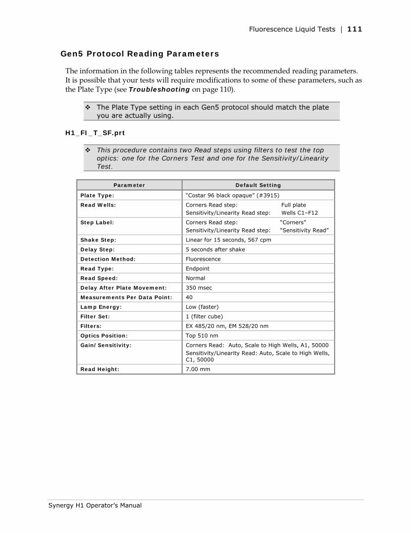
Fluorescence Liquid Tests | 111
Gen5 Protocol Reading Parameters
The information in the following tables represents the recommended reading parameters. It is possible that your tests will require modifications to some of these parameters, such as the Plate Type (see Troubleshooting on page 110).
The Plate Type setting in each Gen5 protocol should match the plate you are actually using.
H1_FI_T_SF.prt
This procedure contains two Read steps using filters to test the top optics: one for the Corners Test and one for the Sensitivity/Linearity Test.
Parameter Default Setting
Plate Type: “Costar 96 black opaque” (#3915)
Read Wells: Corners Read step: Full plate Sensitivity/Linearity Read step: Wells C1–F12
Step Label: Corners Read step: “Corners” Sensitivity/Linearity Read step: “Sensitivity Read”
Shake Step: Linear for 15 seconds, 567 cpm
Delay Step: 5 seconds after shake
Detection Method: Fluorescence
Read Type: Endpoint
Read Speed: Normal
Delay After Plate Movement: 350 msec
Measurements Per Data Point: 40
Lamp Energy: Low (faster)
Filter Set: 1 (filter cube)
Filters: EX 485/20 nm, EM 528/20 nm
Optics Position: Top 510 nm
Gain/Sensitivity: Corners Read: Auto, Scale to High Wells, A1, 50000 Sensitivity/Linearity Read: Auto, Scale to High Wells, C1, 50000
Read Height: 7.00 mm
Synergy H1 Operator’s Manual
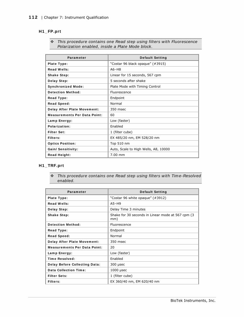
112 | Chapter 7: Instrument Qualification
H1_FP.prt
This procedure contains one Read step using filters with Fluorescence Polarization enabled, inside a Plate Mode block.
Parameter Default Setting
Plate Type: “Costar 96 black opaque” (#3915)
Read Wells: A6–H8
Shake Step: Linear for 15 seconds, 567 cpm
Delay Step: 5 seconds after shake
Synchronized Mode: Plate Mode with Timing Control
Detection Method: Fluorescence
Read Type: Endpoint
Read Speed: Normal
Delay After Plate Movement: 350 msec
Measurements Per Data Point: 60
Lamp Energy: Low (faster)
Polarization: Enabled
Filter Set: 1 (filter cube)
Filters: EX 485/20 nm, EM 528/20 nm
Optics Position: Top 510 nm
Gain/Sensitivity: Auto, Scale to High Wells, A8, 10000
Read Height: 7.00 mm
H1_TRF.prt
This procedure contains one Read step using filters with Time-Resolved enabled.
Parameter Default Setting
Plate Type: “Costar 96 white opaque” (#3912)
Read Wells: A5–H9
Delay Step: Delay Time 3 minutes
Shake Step: Shake for 30 seconds in Linear mode at 567 cpm (3 mm)
Detection Method: Fluorescence
Read Type: Endpoint
Read Speed: Normal
Delay After Plate Movement: 350 msec
Measurements Per Data Point: 20
Lamp Energy: Low (faster)
Time Resolved: Enabled
Delay Before Collecting Data: 300 µsec
Data Collection Time: 1000 µsec
Filter Sets: 1 (filter cube)
Filters: EX 360/40 nm, EM 620/40 nm
BioTek Instruments, Inc.
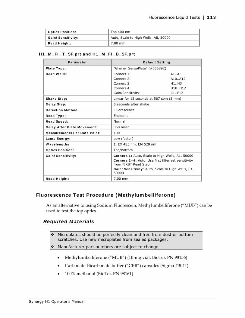
Fluorescence Liquid Tests | 113
Optics Position: Top 400 nm
Gain/Sensitivity: Auto, Scale to High Wells, A8, 50000
Read Height: 7.00 mm
H1_M_FI_T_SF.prt and H1_M_FI_B_SF.prt
Parameter Default Setting
Plate Type: “Greiner SensoPlate” (#655892)
Read Wells: Corners 1: A1..A3 Corners 2: A10..A12 Corners 3: H1..H3 Corners 4: H10..H12 Gain/Sensitivity: C1..F12
Shake Step: Linear for 15 seconds at 567 cpm (3 mm)
Delay Step: 5 seconds after shake
Detection Method: Fluorescence
Read Type: Endpoint
Read Speed: Normal
Delay After Plate Movement: 350 msec
Measurements Per Data Point: 100
Lamp Energy: Low (faster)
Wavelengths 1, EX 485 nm, EM 528 nm
Optics Position: Top/Bottom
Gain/Sensitivity: Corners 1: Auto, Scale to High Wells, A1, 50000 Corners 2–4: Auto, Use first filter set sensitivity from FIRST Read Step Gain/Sensitivity: Auto, Scale to High Wells, C1, 50000
Read Height: 7.00 mm
Fluorescence Test Procedure (Methylumbelliferone)
As an alternative to using Sodium Fluorescein, Methylumbelliferone (“MUB”) can be used to test the top optics.
Required Materials
Microplates should be perfectly clean and free from dust or bottom scratches. Use new microplates from sealed packages.
Manufacturer part numbers are subject to change.
• Methylumbelliferone (“MUB”) (10-mg vial, BioTek PN 98156)
• Carbonate-Bicarbonate buffer (“CBB”) capsules (Sigma #3041)
• 100% methanol (BioTek PN 98161)
Synergy H1 Operator’s Manual
114 | Chapter 7: Instrument Qualification
• A new, clean 96-well solid black microplate, such as Corning Costar #3915, or equivalent. A Greiner SensoPlate (Mfr. #655892) may also be used. If your reader is equipped with the filter- and monochromator-based fluorescence systems, the same plate is used to test both systems.
• 360/40 nm Excitation filter installed
• 460/40 nm Emission filter installed
• 400 nm dichroic mirror installed
• Deionized or distilled water
• Various beakers, graduated cylinders, and pipettes
• 95% ethanol (for cleaning clear-bottom plates)
• Aluminum foil
• (Optional, but recommended) 0.45-micron filter
• (Optional) Black polyethylene bag(s) to temporarily store plate(s)
• Gen5 protocol(s) described on page 118
• H1_FI_T_MUB.prt tests the filter-based fluorescence system
• H1_M_FI_T_MUB.prt tests the monochromator-based fluorescence system
Test Solutions
We recommend that you filter solutions to remove particulates that could cause erroneous readings. Do not allow dust to settle on the surface of the solution; use microplate covers or seals when not reading the plate.
Wrap the vial containing the MUB stock solution in foil to prevent exposure to light.
Discard any open, unused solutions after seven days.
1. Prepare the buffer (CBB) solution:
• (Optional, but recommended) Using a 0.45-micron filter, filter 200 mL of deionized or distilled water.
• Open and dissolve the contents of two CBB capsules (do not dissolve the outer gelatin capsule) into 200 mL of the water.
• Stir the solution (preferably using a stir table) until the CBB is completely dissolved.
BioTek Instruments, Inc.
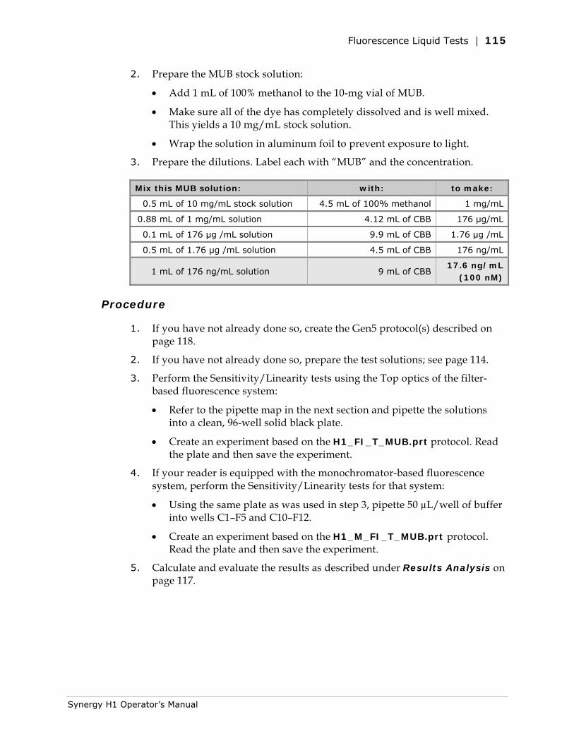
Fluorescence Liquid Tests | 115
2. Prepare the MUB stock solution:
• Add 1 mL of 100% methanol to the 10-mg vial of MUB.
• Make sure all of the dye has completely dissolved and is well mixed. This yields a 10 mg/mL stock solution.
• Wrap the solution in aluminum foil to prevent exposure to light.
3. Prepare the dilutions. Label each with “MUB” and the concentration.
Mix this MUB solution: with: to make:
0.5 mL of 10 mg/mL stock solution 4.5 mL of 100% methanol 1 mg/mL
0.88 mL of 1 mg/mL solution 4.12 mL of CBB 176 μg/mL
0.1 mL of 176 μg /mL solution 9.9 mL of CBB 1.76 μg /mL
0.5 mL of 1.76 μg /mL solution 4.5 mL of CBB 176 ng/mL
1 mL of 176 ng/mL solution 9 mL of CBB 17.6 ng/mL
(100 nM)
Procedure
1. If you have not already done so, create the Gen5 protocol(s) described on page 118.
2. If you have not already done so, prepare the test solutions; see page 114.
3. Perform the Sensitivity/Linearity tests using the Top optics of the filter-based fluorescence system:
• Refer to the pipette map in the next section and pipette the solutions into a clean, 96-well solid black plate.
• Create an experiment based on the H1_FI_T_MUB.prt protocol. Read the plate and then save the experiment.
4. If your reader is equipped with the monochromator-based fluorescence system, perform the Sensitivity/Linearity tests for that system:
• Using the same plate as was used in step 3, pipette 50 µL/well of buffer into wells C1–F5 and C10–F12.
• Create an experiment based on the H1_M_FI_T_MUB.prt protocol. Read the plate and then save the experiment.
5. Calculate and evaluate the results as described under Results Analysis on page 117.
Synergy H1 Operator’s Manual
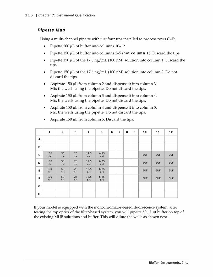
116 | Chapter 7: Instrument Qualification
Pipette Map
Using a multi-channel pipette with just four tips installed to process rows C–F:
• Pipette 200 µL of buffer into columns 10–12.
• Pipette 150 µL of buffer into columns 2–5 (not column 1). Discard the tips.
• Pipette 150 µL of the 17.6 ng/mL (100 nM) solution into column 1. Discard the tips.
• Pipette 150 µL of the 17.6 ng/mL (100 nM) solution into column 2. Do not discard the tips.
• Aspirate 150 µL from column 2 and dispense it into column 3. Mix the wells using the pipette. Do not discard the tips.
• Aspirate 150 µL from column 3 and dispense it into column 4. Mix the wells using the pipette. Do not discard the tips.
• Aspirate 150 µL from column 4 and dispense it into column 5. Mix the wells using the pipette. Do not discard the tips.
• Aspirate 150 µL from column 5. Discard the tips.
1 2 3 4 5 6 7 8 9 10 11 12
A
B
C 100 nM
50 nM
25 nM
12.5 nM
6.25 nM
BUF BUF BUF
D 100 nM
50 nM
25 nM
12.5 nM
6.25 nM
BUF BUF BUF
E 100 nM
50 nM
25 nM
12.5 nM
6.25 nM
BUF BUF BUF
F 100 nM
50 nM
25 nM
12.5 nM
6.25 nM
BUF BUF BUF
G
H
If your model is equipped with the monochromator-based fluorescence system, after testing the top optics of the filter-based system, you will pipette 50 µL of buffer on top of the existing MUB solutions and buffer. This will dilute the wells as shown next.
BioTek Instruments, Inc.
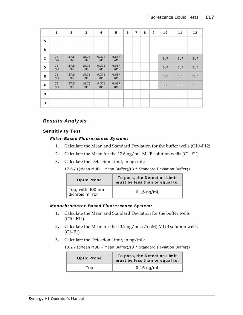
Fluorescence Liquid Tests | 117
1 2 3 4 5 6 7 8 9 10 11 12
A
B
C 75 nM
37.5 nM
18.75 nM
9.375 nM
4.687 nM
BUF BUF BUF
D 75 nM
37.5 nM
18.75 nM
9.375 nM
4.687 nM
BUF BUF BUF
E 75 nM
37.5 nM
18.75 nM
9.375 nM
4.687 nM
BUF BUF BUF
F 75 nM
37.5 nM
18.75 nM
9.375 nM
4.687 nM
BUF BUF BUF
G
H
Results Analysis
Sensitivity Test
Filter-Based Fluorescence System:
1. Calculate the Mean and Standard Deviation for the buffer wells (C10–F12).
2. Calculate the Mean for the 17.6 ng/mL MUB solution wells (C1–F1).
3. Calculate the Detection Limit, in ng/mL: 17.6 / ((Mean MUB – Mean Buffer)/(3 * Standard Deviation Buffer))
Optic Probe To pass, the Detection Limit
must be less than or equal to:
Top, with 400 nm dichroic mirror
0.16 ng/mL
Monochromator-Based Fluorescence System:
1. Calculate the Mean and Standard Deviation for the buffer wells (C10–F12).
2. Calculate the Mean for the 13.2 ng/mL (75 nM) MUB solution wells (C1–F1).
3. Calculate the Detection Limit, in ng/mL: 13.2 / ((Mean MUB – Mean Buffer)/(3 * Standard Deviation Buffer))
Optic Probe To pass, the Detection Limit
must be less than or equal to:
Top 0.16 ng/mL
Synergy H1 Operator’s Manual
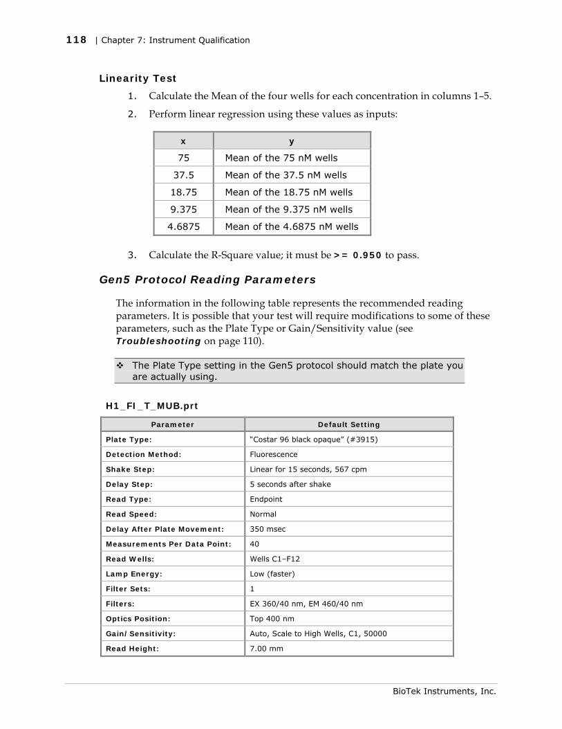
118 | Chapter 7: Instrument Qualification
Linearity Test
1. Calculate the Mean of the four wells for each concentration in columns 1–5.
2. Perform linear regression using these values as inputs:
x y
75 Mean of the 75 nM wells
37.5 Mean of the 37.5 nM wells
18.75 Mean of the 18.75 nM wells
9.375 Mean of the 9.375 nM wells
4.6875 Mean of the 4.6875 nM wells
3. Calculate the R-Square value; it must be >= 0.950 to pass.
Gen5 Protocol Reading Parameters
The information in the following table represents the recommended reading parameters. It is possible that your test will require modifications to some of these parameters, such as the Plate Type or Gain/Sensitivity value (see Troubleshooting on page 110).
The Plate Type setting in the Gen5 protocol should match the plate you are actually using.
H1_FI_T_MUB.prt
Parameter Default Setting
Plate Type: “Costar 96 black opaque” (#3915)
Detection Method: Fluorescence
Shake Step: Linear for 15 seconds, 567 cpm
Delay Step: 5 seconds after shake
Read Type: Endpoint
Read Speed: Normal
Delay After Plate Movement: 350 msec
Measurements Per Data Point: 40
Read Wells: Wells C1–F12
Lamp Energy: Low (faster)
Filter Sets: 1
Filters: EX 360/40 nm, EM 460/40 nm
Optics Position: Top 400 nm
Gain/Sensitivity: Auto, Scale to High Wells, C1, 50000
Read Height: 7.00 mm
BioTek Instruments, Inc.
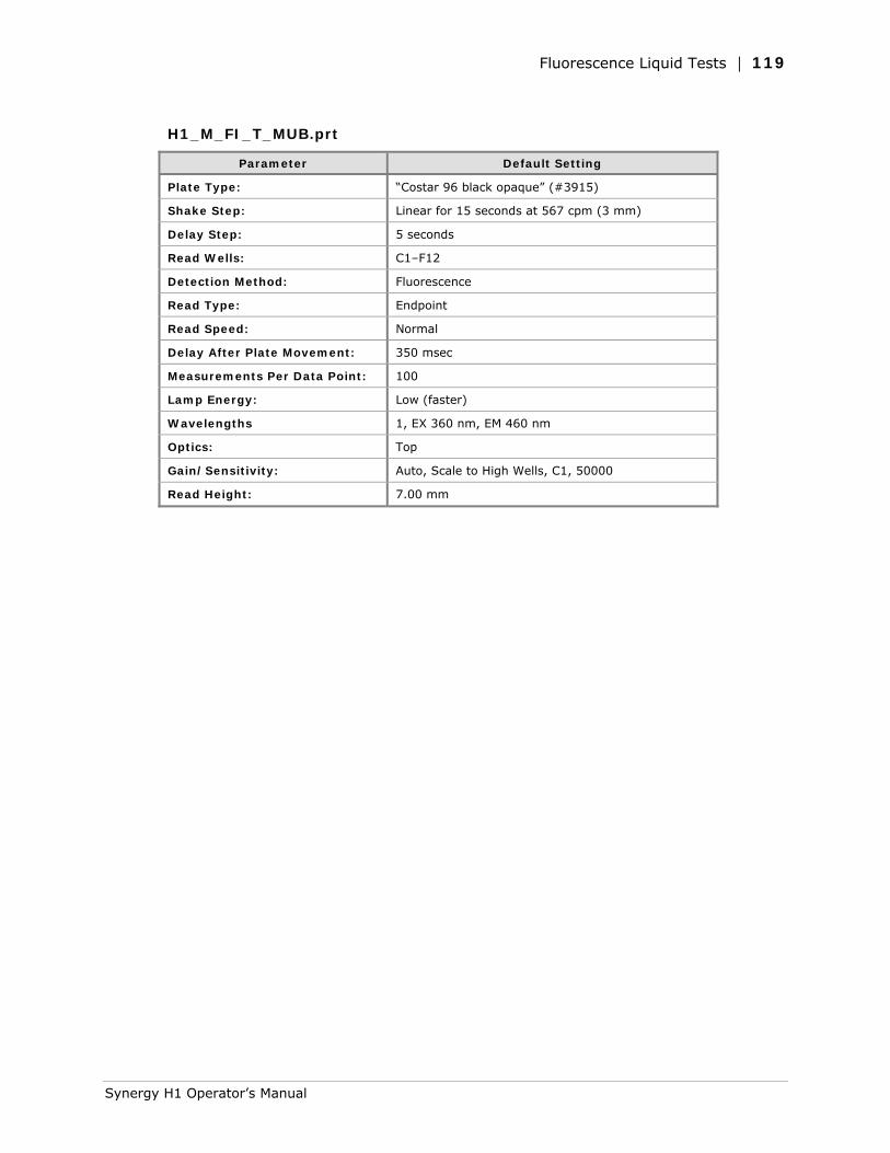
Fluorescence Liquid Tests | 119
H1_M_FI_T_MUB.prt
Parameter Default Setting
Plate Type: “Costar 96 black opaque” (#3915)
Shake Step: Linear for 15 seconds at 567 cpm (3 mm)
Delay Step: 5 seconds
Read Wells: C1–F12
Detection Method: Fluorescence
Read Type: Endpoint
Read Speed: Normal
Delay After Plate Movement: 350 msec
Measurements Per Data Point: 100
Lamp Energy: Low (faster)
Wavelengths 1, EX 360 nm, EM 460 nm
Optics: Top
Gain/Sensitivity: Auto, Scale to High Wells, C1, 50000
Read Height: 7.00 mm
Synergy H1 Operator’s Manual
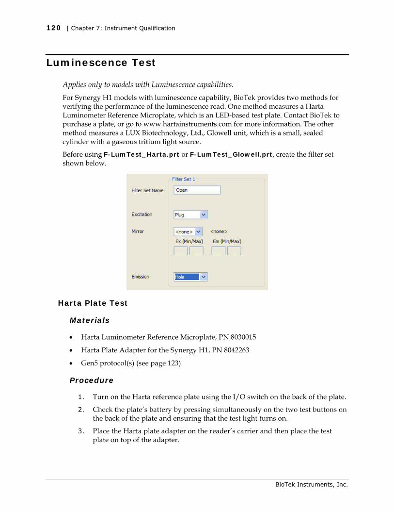
120 | Chapter 7: Instrument Qualification
Luminescence Test
Applies only to models with Luminescence capabilities. For Synergy H1 models with luminescence capability, BioTek provides two methods for verifying the performance of the luminescence read. One method measures a Harta Luminometer Reference Microplate, which is an LED-based test plate. Contact BioTek to purchase a plate, or go to www.hartainstruments.com for more information. The other method measures a LUX Biotechnology, Ltd., Glowell unit, which is a small, sealed cylinder with a gaseous tritium light source.
Before using F-LumTest_Harta.prt or F-LumTest_Glowell.prt, create the filter set shown below.
Harta Plate Test
Materials
• Harta Luminometer Reference Microplate, PN 8030015
• Harta Plate Adapter for the Synergy H1, PN 8042263
• Gen5 protocol(s) (see page 123)
Procedure
1. Turn on the Harta reference plate using the I/O switch on the back of the plate.
2. Check the plate’s battery by pressing simultaneously on the two test buttons on the back of the plate and ensuring that the test light turns on.
3. Place the Harta plate adapter on the reader’s carrier and then place the test plate on top of the adapter.
BioTek Instruments, Inc.
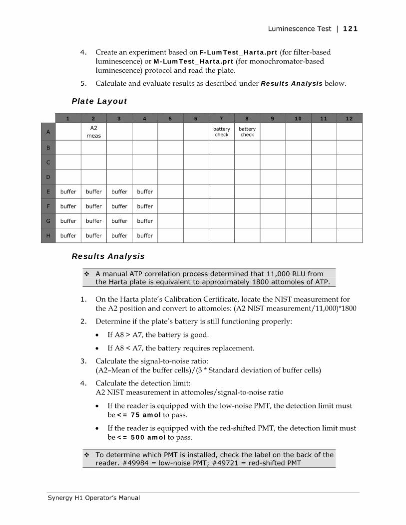
Luminescence Test | 121
4. Create an experiment based on F-LumTest_Harta.prt (for filter-based luminescence) or M-LumTest_Harta.prt (for monochromator-based luminescence) protocol and read the plate.
5. Calculate and evaluate results as described under Results Analysis below.
Plate Layout
1 2 3 4 5 6 7 8 9 10 11 12
A A2
meas battery
check battery check
B
C
D
E buffer buffer buffer buffer
F buffer buffer buffer buffer
G buffer buffer buffer buffer
H buffer buffer buffer buffer
Results Analysis
A manual ATP correlation process determined that 11,000 RLU from the Harta plate is equivalent to approximately 1800 attomoles of ATP.
1. On the Harta plate’s Calibration Certificate, locate the NIST measurement for the A2 position and convert to attomoles: (A2 NIST measurement/11,000)*1800
2. Determine if the plate’s battery is still functioning properly:
• If A8 > A7, the battery is good.
• If A8 < A7, the battery requires replacement.
3. Calculate the signal-to-noise ratio: (A2–Mean of the buffer cells)/(3 * Standard deviation of buffer cells)
4. Calculate the detection limit: A2 NIST measurement in attomoles/signal-to-noise ratio
• If the reader is equipped with the low-noise PMT, the detection limit must be <= 75 amol to pass.
• If the reader is equipped with the red-shifted PMT, the detection limit must be <= 500 amol to pass.
To determine which PMT is installed, check the label on the back of the reader. #49984 = low-noise PMT; #49721 = red-shifted PMT
Synergy H1 Operator’s Manual
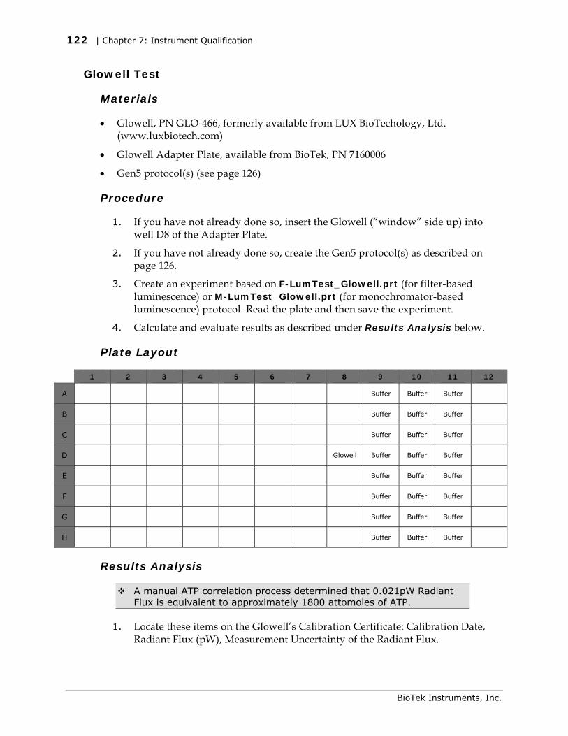
122 | Chapter 7: Instrument Qualification
Glowell Test
Materials
• Glowell, PN GLO-466, formerly available from LUX BioTechology, Ltd. (www.luxbiotech.com)
• Glowell Adapter Plate, available from BioTek, PN 7160006
• Gen5 protocol(s) (see page 126)
Procedure
1. If you have not already done so, insert the Glowell (“window” side up) into well D8 of the Adapter Plate.
2. If you have not already done so, create the Gen5 protocol(s) as described on page 126.
3. Create an experiment based on F-LumTest_Glowell.prt (for filter-based luminescence) or M-LumTest_Glowell.prt (for monochromator-based luminescence) protocol. Read the plate and then save the experiment.
4. Calculate and evaluate results as described under Results Analysis below.
Plate Layout
1 2 3 4 5 6 7 8 9 10 11 12
A Buffer Buffer Buffer
B Buffer Buffer Buffer
C Buffer Buffer Buffer
D Glowell Buffer Buffer Buffer
E Buffer Buffer Buffer
F Buffer Buffer Buffer
G Buffer Buffer Buffer
H Buffer Buffer Buffer
Results Analysis
A manual ATP correlation process determined that 0.021pW Radiant Flux is equivalent to approximately 1800 attomoles of ATP.
1. Locate these items on the Glowell’s Calibration Certificate: Calibration Date, Radiant Flux (pW), Measurement Uncertainty of the Radiant Flux.
BioTek Instruments, Inc.
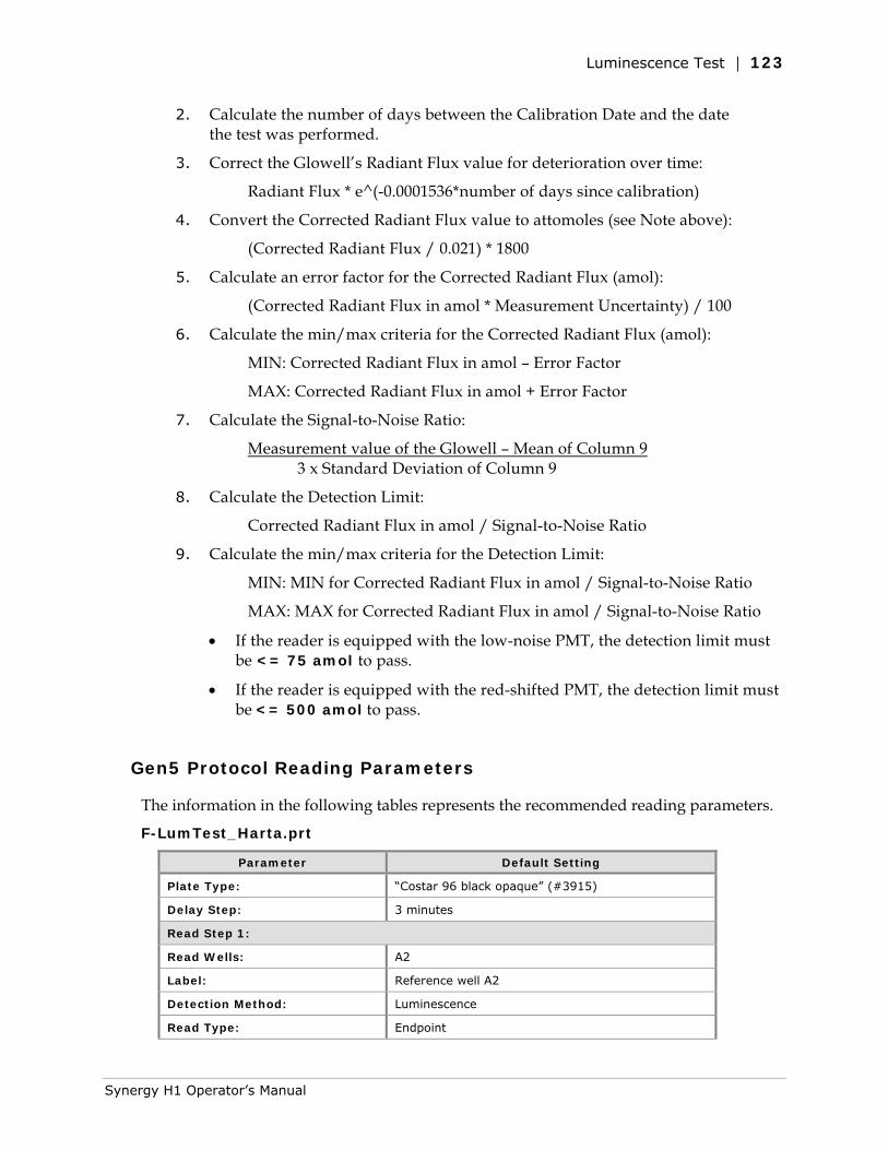
Luminescence Test | 123
2. Calculate the number of days between the Calibration Date and the date the test was performed.
3. Correct the Glowell’s Radiant Flux value for deterioration over time:
Radiant Flux * e^(-0.0001536*number of days since calibration)
4. Convert the Corrected Radiant Flux value to attomoles (see Note above):
(Corrected Radiant Flux / 0.021) * 1800
5. Calculate an error factor for the Corrected Radiant Flux (amol):
(Corrected Radiant Flux in amol * Measurement Uncertainty) / 100
6. Calculate the min/max criteria for the Corrected Radiant Flux (amol):
MIN: Corrected Radiant Flux in amol – Error Factor
MAX: Corrected Radiant Flux in amol + Error Factor
7. Calculate the Signal-to-Noise Ratio:
Measurement value of the Glowell – Mean of Column 9 3 x Standard Deviation of Column 9
8. Calculate the Detection Limit:
Corrected Radiant Flux in amol / Signal-to-Noise Ratio
9. Calculate the min/max criteria for the Detection Limit:
MIN: MIN for Corrected Radiant Flux in amol / Signal-to-Noise Ratio
MAX: MAX for Corrected Radiant Flux in amol / Signal-to-Noise Ratio
• If the reader is equipped with the low-noise PMT, the detection limit must be <= 75 amol to pass.
• If the reader is equipped with the red-shifted PMT, the detection limit must be <= 500 amol to pass.
Gen5 Protocol Reading Parameters
The information in the following tables represents the recommended reading parameters.
F-LumTest_Harta.prt
Parameter Default Setting
Plate Type: “Costar 96 black opaque” (#3915)
Delay Step: 3 minutes
Read Step 1:
Read Wells: A2
Label: Reference well A2
Detection Method: Luminescence
Read Type: Endpoint
Synergy H1 Operator’s Manual
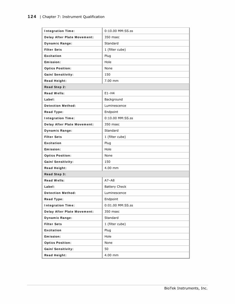
124 | Chapter 7: Instrument Qualification
Integration Time: 0:10.00 MM:SS.ss
Delay After Plate Movement: 350 msec
Dynamic Range: Standard
Filter Sets 1 (filter cube)
Excitation Plug
Emission: Hole
Optics Position: None
Gain/Sensitivity: 150
Read Height: 7.00 mm
Read Step 2:
Read Wells: E1–H4
Label: Background
Detection Method: Luminescence
Read Type: Endpoint
Integration Time: 0:10.00 MM:SS.ss
Delay After Plate Movement: 350 msec
Dynamic Range: Standard
Filter Sets 1 (filter cube)
Excitation Plug
Emission: Hole
Optics Position: None
Gain/Sensitivity: 150
Read Height: 4.00 mm
Read Step 3:
Read Wells: A7–A8
Label: Battery Check
Detection Method: Luminescence
Read Type: Endpoint
Integration Time: 0:01.00 MM:SS.ss
Delay After Plate Movement: 350 msec
Dynamic Range: Standard
Filter Sets 1 (filter cube)
Excitation Plug
Emission: Hole
Optics Position: None
Gain/Sensitivity: 50
Read Height: 4.00 mm
BioTek Instruments, Inc.
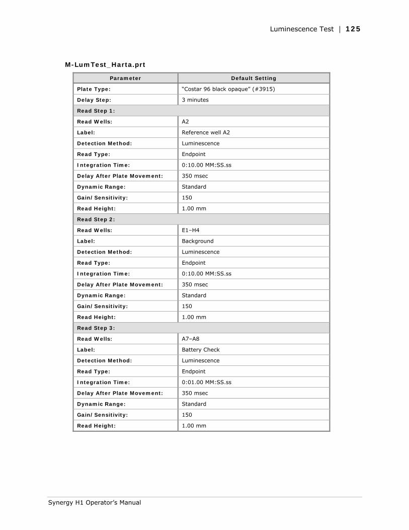
Luminescence Test | 125
M-LumTest_Harta.prt
Parameter Default Setting
Plate Type: “Costar 96 black opaque” (#3915)
Delay Step: 3 minutes
Read Step 1:
Read Wells: A2
Label: Reference well A2
Detection Method: Luminescence
Read Type: Endpoint
Integration Time: 0:10.00 MM:SS.ss
Delay After Plate Movement: 350 msec
Dynamic Range: Standard
Gain/Sensitivity: 150
Read Height: 1.00 mm
Read Step 2:
Read Wells: E1–H4
Label: Background
Detection Method: Luminescence
Read Type: Endpoint
Integration Time: 0:10.00 MM:SS.ss
Delay After Plate Movement: 350 msec
Dynamic Range: Standard
Gain/Sensitivity: 150
Read Height: 1.00 mm
Read Step 3:
Read Wells: A7–A8
Label: Battery Check
Detection Method: Luminescence
Read Type: Endpoint
Integration Time: 0:01.00 MM:SS.ss
Delay After Plate Movement: 350 msec
Dynamic Range: Standard
Gain/Sensitivity: 150
Read Height: 1.00 mm
Synergy H1 Operator’s Manual
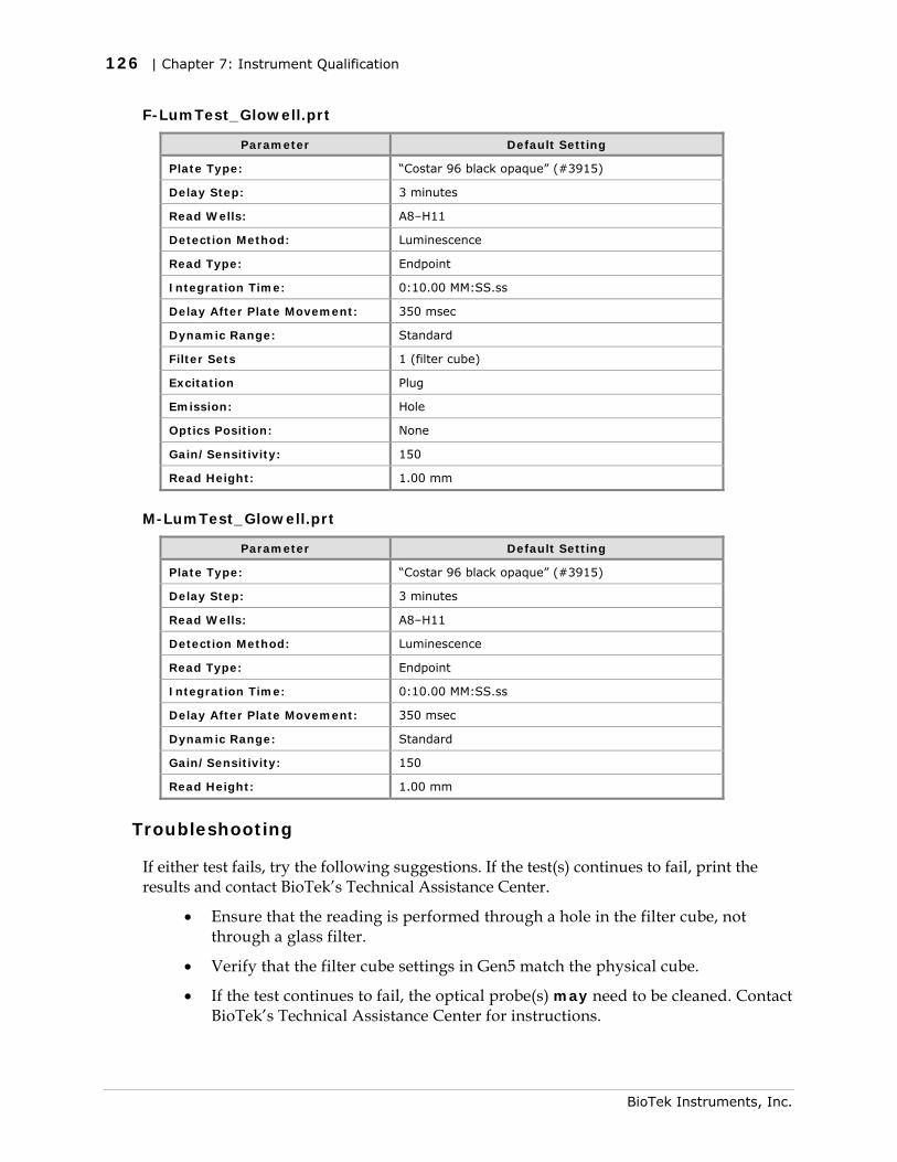
126 | Chapter 7: Instrument Qualification
F-LumTest_Glowell.prt
Parameter Default Setting
Plate Type: “Costar 96 black opaque” (#3915)
Delay Step: 3 minutes
Read Wells: A8–H11
Detection Method: Luminescence
Read Type: Endpoint
Integration Time: 0:10.00 MM:SS.ss
Delay After Plate Movement: 350 msec
Dynamic Range: Standard
Filter Sets 1 (filter cube)
Excitation Plug
Emission: Hole
Optics Position: None
Gain/Sensitivity: 150
Read Height: 1.00 mm
M-LumTest_Glowell.prt
Parameter Default Setting
Plate Type: “Costar 96 black opaque” (#3915)
Delay Step: 3 minutes
Read Wells: A8–H11
Detection Method: Luminescence
Read Type: Endpoint
Integration Time: 0:10.00 MM:SS.ss
Delay After Plate Movement: 350 msec
Dynamic Range: Standard
Gain/Sensitivity: 150
Read Height: 1.00 mm
Troubleshooting
If either test fails, try the following suggestions. If the test(s) continues to fail, print the results and contact BioTek’s Technical Assistance Center.
• Ensure that the reading is performed through a hole in the filter cube, not through a glass filter.
• Verify that the filter cube settings in Gen5 match the physical cube.
• If the test continues to fail, the optical probe(s) may need to be cleaned. Contact BioTek’s Technical Assistance Center for instructions.
BioTek Instruments, Inc.
Dispense Module Tests | 127
Glowell only:
• Is the plate properly inserted into the adapter? The “window”side should be facing up. If necessary, clean the Glowell according to the manufacturer’s instructions.
• Is the adapter plate clean? If dust has collected in the wells, try cleaning the plate using compressed air or an aerosol duster.
• Is the test failing because the standard deviation of the empty background (“buffer”) wells is 0 (resulting in a division-by-zero error in the spreadsheet)? If yes, try pipetting 100 µL of deionized water into all wells of Columns 9, 10, and 11 (the background wells).
Dispense Module Tests
Applies only to models with the Dispense module. BioTek Instruments, Inc., has developed a set of tests that you can perform to ensure that the dispense module performs to specification initially and over time. We recommend that you perform these tests before first use (e.g., during the Initial OQ), and then every three months.
• The Accuracy Test is a measure of the mean volume per well for multiple dispenses. The actual weight of the dispensed fluid is compared to the expected weight and must be within a certain percentage to pass. Pass/Fail criteria depends on the per-well volume dispensed: 2.0% for 80 µL, 5.0% for 20 µL, and 20.0% for 5 µL. It is assumed that one gram is equal to one milliliter. The test uses a single green dye test solution and one 96-well microplate (per injector) to test the three different volumes. The balance is tared with the empty plate, and then the 80 µL dispense is performed for columns 1–4. The fluid is weighed and the balance is tared again (with the plate on the balance). This process is repeated for the 20 µL and 5 µL dispenses. It is assumed that the solutions used are at room temperature. A precision balance (three-place) is used to weigh the plate.
• The Precision Test is a measure of the variation among volumes dispensed to multiple wells. For each volume dispensed (80 µL, 20 µL, and 5 µL) to four columns, the %CV (coefficient of variation) of 32 absorbance readings is calculated. Pass/Fail criteria depends on the per-well volume dispensed: 2.0% for 80 µL, 7.0% for 20 µL, and 10.0% for 5 µL. The plate is read in an absorbance reader at 405/750 nm for columns 1–4 and at 630/750 nm for columns 5–12.
The two tests are performed simultaneously and use the same plate.
Each dispense module is calibrated to perform with a specific Synergy H1 reader. Make sure the dispense module and reader have the same serial number.
Synergy H1 Operator’s Manual
128 | Chapter 7: Instrument Qualification
Required Materials
Manufacturer part numbers are subject to change.
• Absorbance reader with capability of reading at 405, 630, and 750 nm. The reader must have an accuracy specification of ± 1.0% ± 0.010 OD or better and a repeatability specification of ± 1.0% ± 0.005 OD or better.
The Synergy H1 may be used if it is equipped with Absorbance capabilities and has passed the Absorbance Plate Test or Absorbance Liquid Test 2, and Absorbance Liquid Test 1.
• Microplate shaker (if the absorbance reader does not support shaking)
• Precision balance with capacity of 100 g minimum and readability of 0.001 g
• 50–200 µL hand pipette and disposable tips
• Deionized water
• Supply bottles
• 250-mL beaker
• New 96-well, clear, flat-bottom microplates
• BioTek’s Green Test Dye Solution (PN 7773003) undiluted, or one of the alternate test solutions listed in the next section
• 100-mL graduated cylinder and 10-mL pipettes (if not using BioTek’s Green Test Dye Solution)
• Gen5 software installed on the host PC
• Gen5 protocols as defined by the procedure on page 133 or 135.
Alternate Test Solutions
80 µL of test solution with 150 µL of deionized water should read between 1.300 and 1.700 OD at 405/750 nm. The solutions should be at room temperature.
If you do not have BioTek’s Green Test Dye Solution (PN 7773003), prepare a dye solution using one of the following methods:
BioTek Instruments, Inc.
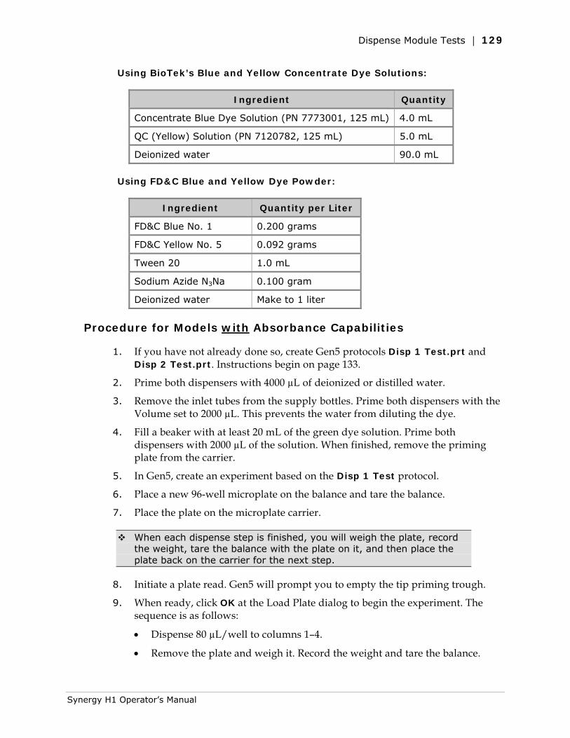
Dispense Module Tests | 129
Using BioTek’s Blue and Yellow Concentrate Dye Solutions:
Ingredient Quantity
Concentrate Blue Dye Solution (PN 7773001, 125 mL) 4.0 mL
QC (Yellow) Solution (PN 7120782, 125 mL) 5.0 mL
Deionized water 90.0 mL
Using FD&C Blue and Yellow Dye Powder:
Ingredient Quantity per Liter
FD&C Blue No. 1 0.200 grams
FD&C Yellow No. 5 0.092 grams
Tween 20 1.0 mL
Sodium Azide N3Na 0.100 gram
Deionized water Make to 1 liter
Procedure for Models with Absorbance Capabilities
1. If you have not already done so, create Gen5 protocols Disp 1 Test.prt and Disp 2 Test.prt. Instructions begin on page 133.
2. Prime both dispensers with 4000 µL of deionized or distilled water.
3. Remove the inlet tubes from the supply bottles. Prime both dispensers with the Volume set to 2000 µL. This prevents the water from diluting the dye.
4. Fill a beaker with at least 20 mL of the green dye solution. Prime both dispensers with 2000 µL of the solution. When finished, remove the priming plate from the carrier.
5. In Gen5, create an experiment based on the Disp 1 Test protocol.
6. Place a new 96-well microplate on the balance and tare the balance.
7. Place the plate on the microplate carrier.
When each dispense step is finished, you will weigh the plate, record the weight, tare the balance with the plate on it, and then place the plate back on the carrier for the next step.
8. Initiate a plate read. Gen5 will prompt you to empty the tip priming trough.
9. When ready, click OK at the Load Plate dialog to begin the experiment. The sequence is as follows:
• Dispense 80 µL/well to columns 1–4.
• Remove the plate and weigh it. Record the weight and tare the balance.
Synergy H1 Operator’s Manual
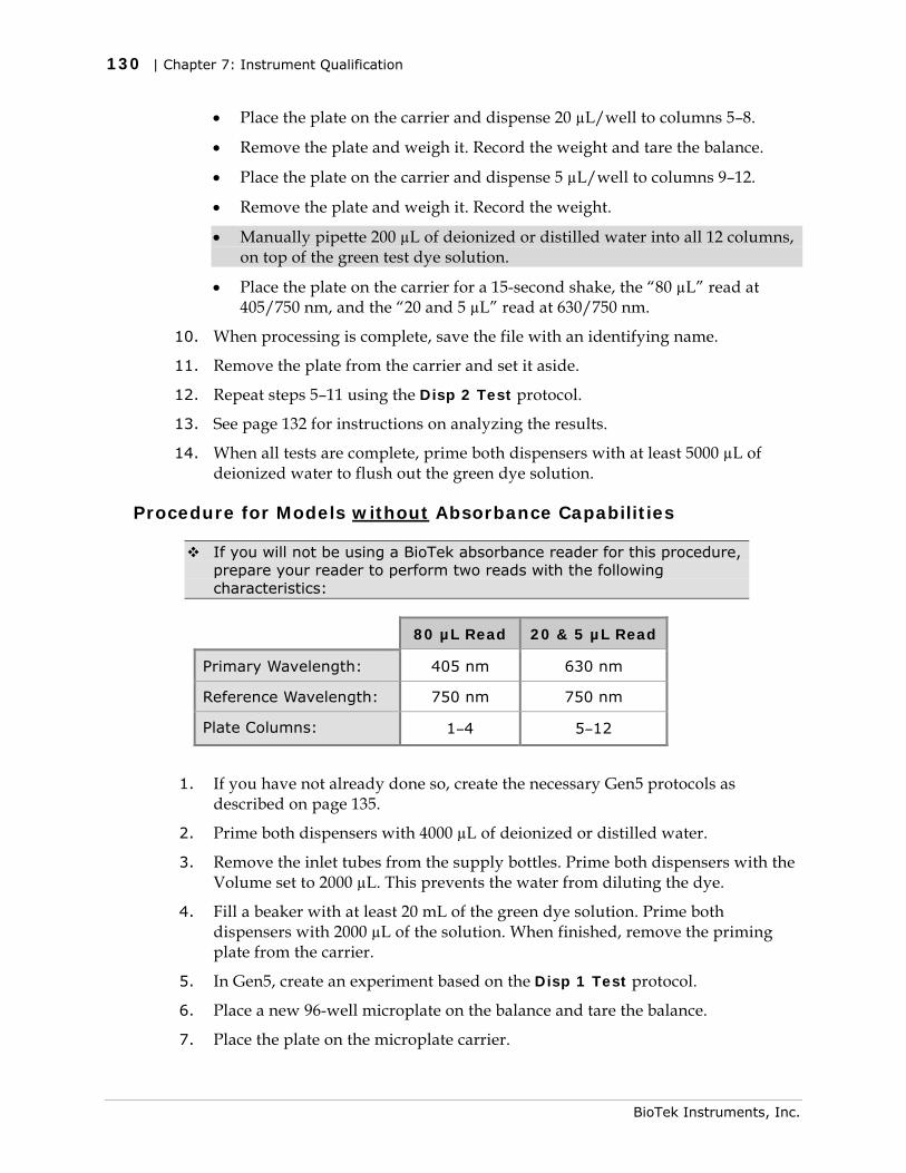
130 | Chapter 7: Instrument Qualification
• Place the plate on the carrier and dispense 20 µL/well to columns 5–8.
• Remove the plate and weigh it. Record the weight and tare the balance.
• Place the plate on the carrier and dispense 5 µL/well to columns 9–12.
• Remove the plate and weigh it. Record the weight.
• Manually pipette 200 µL of deionized or distilled water into all 12 columns, on top of the green test dye solution.
• Place the plate on the carrier for a 15-second shake, the “80 µL” read at 405/750 nm, and the “20 and 5 µL” read at 630/750 nm.
10. When processing is complete, save the file with an identifying name.
11. Remove the plate from the carrier and set it aside.
12. Repeat steps 5–11 using the Disp 2 Test protocol.
13. See page 132 for instructions on analyzing the results.
14. When all tests are complete, prime both dispensers with at least 5000 µL of deionized water to flush out the green dye solution.
Procedure for Models without Absorbance Capabilities
If you will not be using a BioTek absorbance reader for this procedure, prepare your reader to perform two reads with the following characteristics:
80 µL Read 20 & 5 µL Read
Primary Wavelength: 405 nm 630 nm
Reference Wavelength: 750 nm 750 nm
Plate Columns: 1–4 5–12
1. If you have not already done so, create the necessary Gen5 protocols as described on page 135.
2. Prime both dispensers with 4000 µL of deionized or distilled water.
3. Remove the inlet tubes from the supply bottles. Prime both dispensers with the Volume set to 2000 µL. This prevents the water from diluting the dye.
4. Fill a beaker with at least 20 mL of the green dye solution. Prime both dispensers with 2000 µL of the solution. When finished, remove the priming plate from the carrier.
5. In Gen5, create an experiment based on the Disp 1 Test protocol.
6. Place a new 96-well microplate on the balance and tare the balance.
7. Place the plate on the microplate carrier.
BioTek Instruments, Inc.
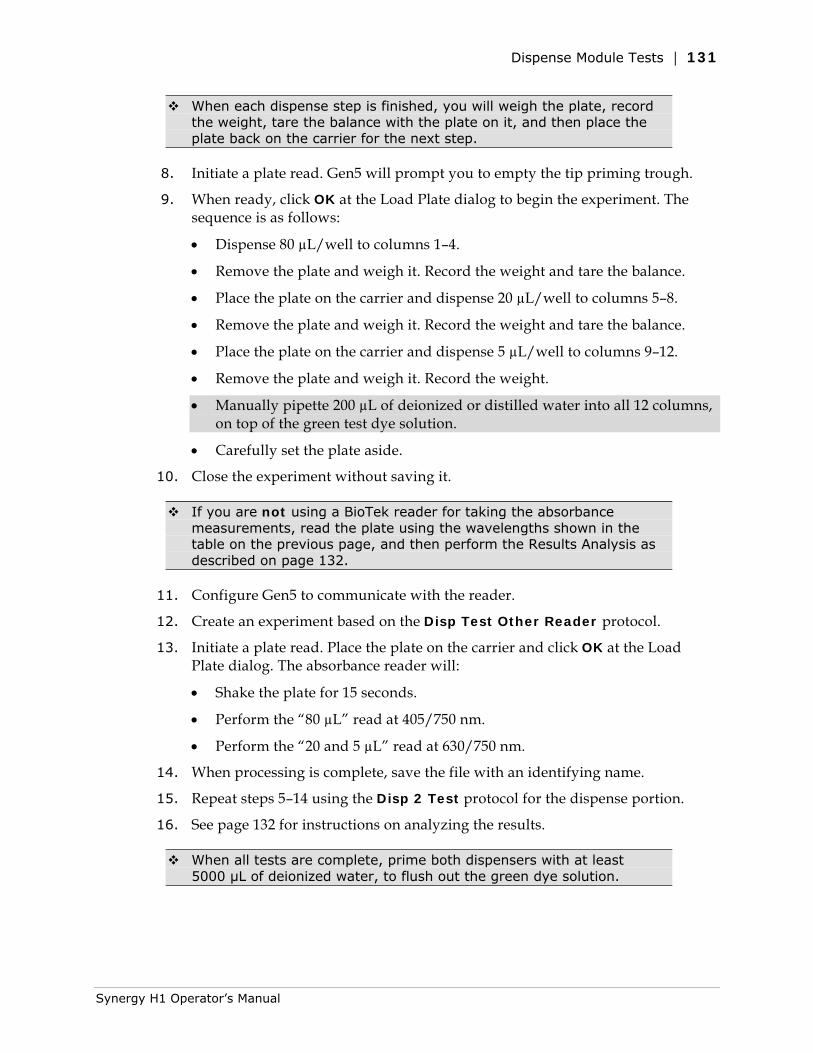
Dispense Module Tests | 131
When each dispense step is finished, you will weigh the plate, record the weight, tare the balance with the plate on it, and then place the plate back on the carrier for the next step.
8. Initiate a plate read. Gen5 will prompt you to empty the tip priming trough.
9. When ready, click OK at the Load Plate dialog to begin the experiment. The sequence is as follows:
• Dispense 80 µL/well to columns 1–4.
• Remove the plate and weigh it. Record the weight and tare the balance.
• Place the plate on the carrier and dispense 20 µL/well to columns 5–8.
• Remove the plate and weigh it. Record the weight and tare the balance.
• Place the plate on the carrier and dispense 5 µL/well to columns 9–12.
• Remove the plate and weigh it. Record the weight.
• Manually pipette 200 µL of deionized or distilled water into all 12 columns, on top of the green test dye solution.
• Carefully set the plate aside.
10. Close the experiment without saving it.
If you are not using a BioTek reader for taking the absorbance measurements, read the plate using the wavelengths shown in the table on the previous page, and then perform the Results Analysis as described on page 132.
11. Configure Gen5 to communicate with the reader.
12. Create an experiment based on the Disp Test Other Reader protocol.
13. Initiate a plate read. Place the plate on the carrier and click OK at the Load Plate dialog. The absorbance reader will:
• Shake the plate for 15 seconds.
• Perform the “80 µL” read at 405/750 nm.
• Perform the “20 and 5 µL” read at 630/750 nm.
14. When processing is complete, save the file with an identifying name.
15. Repeat steps 5–14 using the Disp 2 Test protocol for the dispense portion.
16. See page 132 for instructions on analyzing the results.
When all tests are complete, prime both dispensers with at least 5000 µL of deionized water, to flush out the green dye solution.
Synergy H1 Operator’s Manual
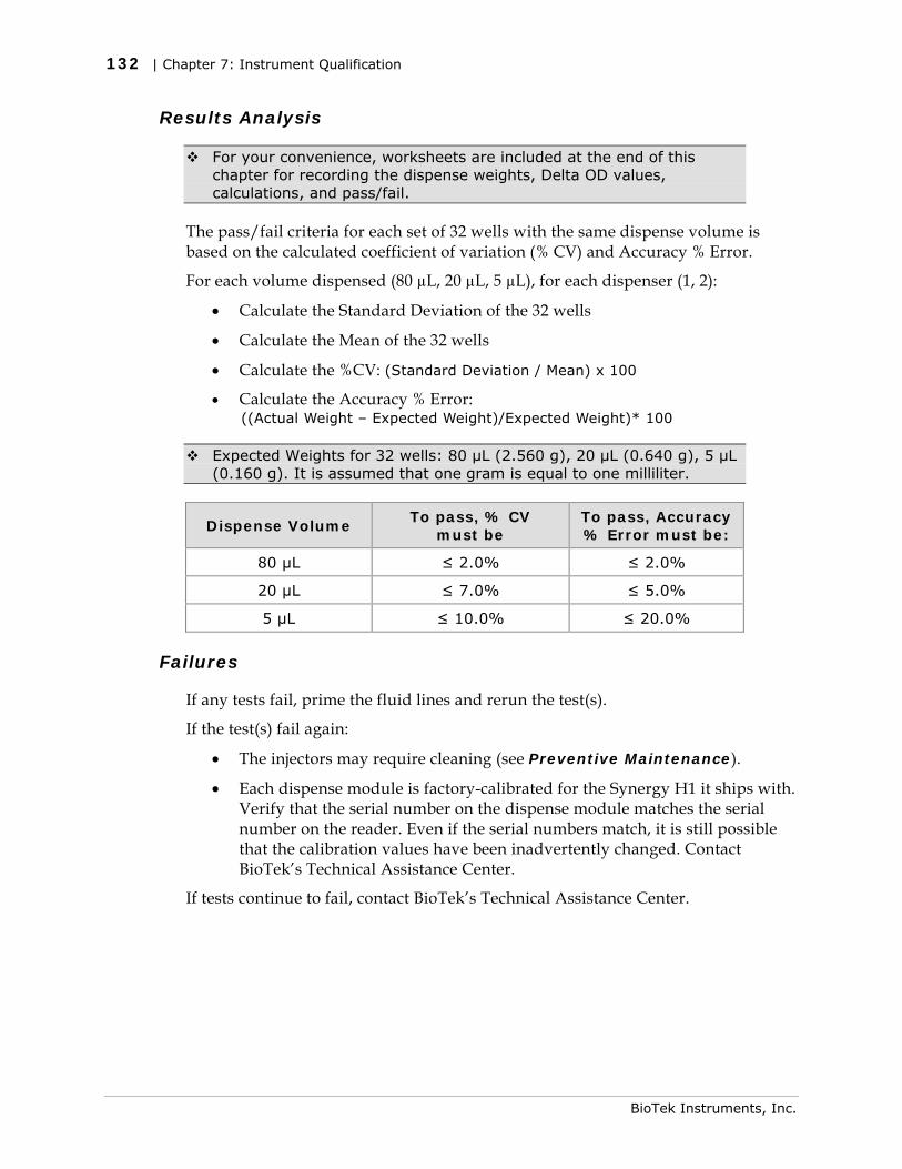
132 | Chapter 7: Instrument Qualification
Results Analysis
For your convenience, worksheets are included at the end of this chapter for recording the dispense weights, Delta OD values, calculations, and pass/fail.
The pass/fail criteria for each set of 32 wells with the same dispense volume is based on the calculated coefficient of variation (% CV) and Accuracy % Error.
For each volume dispensed (80 µL, 20 µL, 5 µL), for each dispenser (1, 2):
• Calculate the Standard Deviation of the 32 wells
• Calculate the Mean of the 32 wells
• Calculate the %CV: (Standard Deviation / Mean) x 100
• Calculate the Accuracy % Error: ((Actual Weight – Expected Weight)/Expected Weight)* 100
Expected Weights for 32 wells: 80 µL (2.560 g), 20 µL (0.640 g), 5 µL (0.160 g). It is assumed that one gram is equal to one milliliter.
Dispense Volume To pass, % CV
must be To pass, Accuracy % Error must be:
80 µL ≤ 2.0% ≤ 2.0%
20 µL ≤ 7.0% ≤ 5.0%
5 µL ≤ 10.0% ≤ 20.0%
Failures
If any tests fail, prime the fluid lines and rerun the test(s).
If the test(s) fail again:
• The injectors may require cleaning (see Preventive Maintenance).
• Each dispense module is factory-calibrated for the Synergy H1 it ships with. Verify that the serial number on the dispense module matches the serial number on the reader. Even if the serial numbers match, it is still possible that the calibration values have been inadvertently changed. Contact BioTek’s Technical Assistance Center.
If tests continue to fail, contact BioTek’s Technical Assistance Center.
BioTek Instruments, Inc.
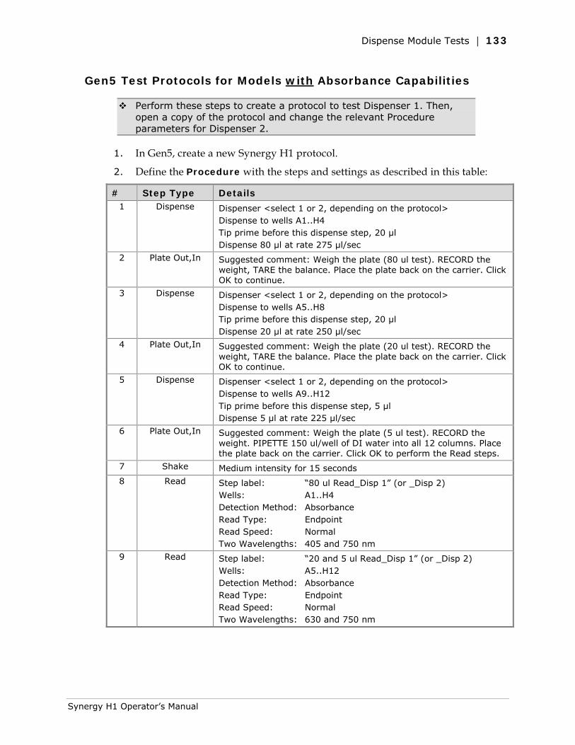
Dispense Module Tests | 133
Gen5 Test Protocols for Models with Absorbance Capabilities
Perform these steps to create a protocol to test Dispenser 1. Then, open a copy of the protocol and change the relevant Procedure parameters for Dispenser 2.
1. In Gen5, create a new Synergy H1 protocol.
2. Define the Procedure with the steps and settings as described in this table:
# Step Type Details 1 Dispense Dispenser <select 1 or 2, depending on the protocol>
Dispense to wells A1..H4 Tip prime before this dispense step, 20 µl Dispense 80 µl at rate 275 µl/sec
2 Plate Out,In Suggested comment: Weigh the plate (80 ul test). RECORD the weight, TARE the balance. Place the plate back on the carrier. Click OK to continue.
3 Dispense Dispenser <select 1 or 2, depending on the protocol> Dispense to wells A5..H8 Tip prime before this dispense step, 20 µl Dispense 20 µl at rate 250 µl/sec
4 Plate Out,In Suggested comment: Weigh the plate (20 ul test). RECORD the weight, TARE the balance. Place the plate back on the carrier. Click OK to continue.
5 Dispense Dispenser <select 1 or 2, depending on the protocol> Dispense to wells A9..H12 Tip prime before this dispense step, 5 µl Dispense 5 µl at rate 225 µl/sec
6 Plate Out,In Suggested comment: Weigh the plate (5 ul test). RECORD the weight. PIPETTE 150 ul/well of DI water into all 12 columns. Place the plate back on the carrier. Click OK to perform the Read steps.
7 Shake Medium intensity for 15 seconds
8 Read Step label: “80 ul Read_Disp 1” (or _Disp 2) Wells: A1..H4 Detection Method: Absorbance Read Type: Endpoint Read Speed: Normal Two Wavelengths: 405 and 750 nm
9 Read Step label: “20 and 5 ul Read_Disp 1” (or _Disp 2) Wells: A5..H12 Detection Method: Absorbance Read Type: Endpoint Read Speed: Normal Two Wavelengths: 630 and 750 nm
Synergy H1 Operator’s Manual
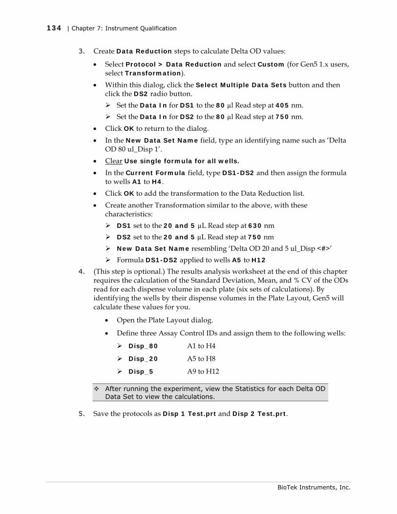
134 | Chapter 7: Instrument Qualification
3. Create Data Reduction steps to calculate Delta OD values:
• Select Protocol > Data Reduction and select Custom (for Gen5 1.x users, select Transformation).
• Within this dialog, click the Select Multiple Data Sets button and then click the DS2 radio button.
Set the Data In for DS1 to the 80 µl Read step at 405 nm. Set the Data In for DS2 to the 80 µl Read step at 750 nm.
• Click OK to return to the dialog. • In the New Data Set Name field, type an identifying name such as ‘Delta
OD 80 ul_Disp 1’. • Clear Use single formula for all wells. • In the Current Formula field, type DS1-DS2 and then assign the formula
to wells A1 to H4. • Click OK to add the transformation to the Data Reduction list. • Create another Transformation similar to the above, with these
characteristics: DS1 set to the 20 and 5 µL Read step at 630 nm DS2 set to the 20 and 5 µL Read step at 750 nm New Data Set Name resembling ‘Delta OD 20 and 5 ul_Disp <#>’ Formula DS1-DS2 applied to wells A5 to H12
4. (This step is optional.) The results analysis worksheet at the end of this chapter requires the calculation of the Standard Deviation, Mean, and % CV of the ODs read for each dispense volume in each plate (six sets of calculations). By identifying the wells by their dispense volumes in the Plate Layout, Gen5 will calculate these values for you.
• Open the Plate Layout dialog.
• Define three Assay Control IDs and assign them to the following wells:
Disp_80 A1 to H4
Disp_20 A5 to H8
Disp_5 A9 to H12
After running the experiment, view the Statistics for each Delta OD Data Set to view the calculations.
5. Save the protocols as Disp 1 Test.prt and Disp 2 Test.prt.
BioTek Instruments, Inc.
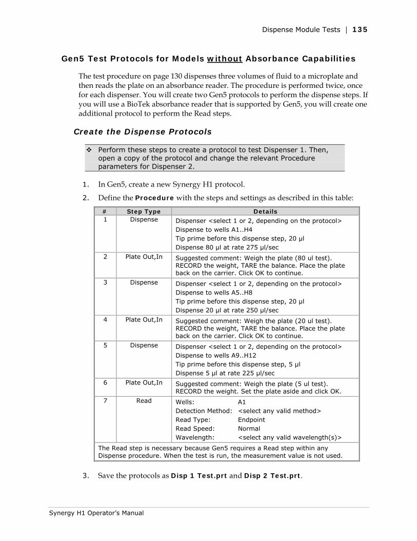
Dispense Module Tests | 135
Gen5 Test Protocols for Models without Absorbance Capabilities
The test procedure on page 130 dispenses three volumes of fluid to a microplate and then reads the plate on an absorbance reader. The procedure is performed twice, once for each dispenser. You will create two Gen5 protocols to perform the dispense steps. If you will use a BioTek absorbance reader that is supported by Gen5, you will create one additional protocol to perform the Read steps.
Create the Dispense Protocols
Perform these steps to create a protocol to test Dispenser 1. Then, open a copy of the protocol and change the relevant Procedure parameters for Dispenser 2.
1. In Gen5, create a new Synergy H1 protocol.
2. Define the Procedure with the steps and settings as described in this table:
# Step Type Details 1 Dispense Dispenser <select 1 or 2, depending on the protocol>
Dispense to wells A1..H4 Tip prime before this dispense step, 20 µl Dispense 80 µl at rate 275 µl/sec
2 Plate Out,In Suggested comment: Weigh the plate (80 ul test). RECORD the weight, TARE the balance. Place the plate back on the carrier. Click OK to continue.
3 Dispense Dispenser <select 1 or 2, depending on the protocol> Dispense to wells A5..H8 Tip prime before this dispense step, 20 µl Dispense 20 µl at rate 250 µl/sec
4 Plate Out,In Suggested comment: Weigh the plate (20 ul test). RECORD the weight, TARE the balance. Place the plate back on the carrier. Click OK to continue.
5 Dispense Dispenser <select 1 or 2, depending on the protocol> Dispense to wells A9..H12 Tip prime before this dispense step, 5 µl Dispense 5 µl at rate 225 µl/sec
6 Plate Out,In Suggested comment: Weigh the plate (5 ul test). RECORD the weight. Set the plate aside and click OK.
7 Read Wells: A1 Detection Method: <select any valid method> Read Type: Endpoint Read Speed: Normal Wavelength: <select any valid wavelength(s)>
The Read step is necessary because Gen5 requires a Read step within any Dispense procedure. When the test is run, the measurement value is not used.
3. Save the protocols as Disp 1 Test.prt and Disp 2 Test.prt.
Synergy H1 Operator’s Manual
136 | Chapter 7: Instrument Qualification
Create the Read Protocol (if needed)
1. In Gen5, create a new protocol for the BioTek reader.
2. Define the Procedure with the steps and settings as described in this table:
# Step Type Details 1 Shake Medium intensity for 15 seconds
2 Read Step label: “80 ul Read” Wells: A1..H4 Detection Method: Absorbance Read Type: Endpoint Read Speed: Normal Two Wavelengths: 405 and 750 nm
3 Read Step label: “20 and 5 ul Read” Wells: A5..H12 Detection Method: Absorbance Read Type: Endpoint Read Speed: Normal Two Wavelengths: 630 and 750 nm
3. Create Data Reduction steps to calculate Delta OD values:
• Select Protocol > Data Reduction and select Custom (for Gen5 1.x users, select Transformation).
• Within this dialog, click the Select Multiple Data Sets button and then click the DS2 radio button.
Set the Data In for DS1 to the 80 µl Read step at 405 nm.
Set the Data In for DS2 to the 80 µl Read step at 750 nm.
• Click OK to return to the dialog.
• In the New Data Set Name field, type an identifying name such as ‘Delta OD 80 ul_Disp 1’.
• Clear Use single formula for all wells.
• In the Current Formula field, type DS1-DS2 and then assign the formula to wells A1 to H4.
• Click OK to add the transformation to the Data Reduction list.
• Create another Transformation similar to the above, with these characteristics:
DS1 set to the 20 and 5 µL Read step at 630 nm
DS2 set to the 20 and 5 µL Read step at 750 nm
New Data Set Name resembling ‘Delta OD 20 and 5 ul_Disp <#>’
Formula DS1-DS2 applied to wells A5 to H12
BioTek Instruments, Inc.
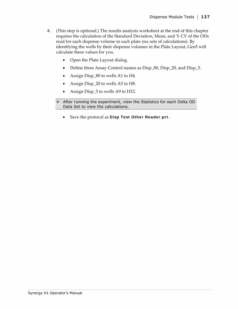
Dispense Module Tests | 137
4. (This step is optional.) The results analysis worksheet at the end of this chapter requires the calculation of the Standard Deviation, Mean, and % CV of the ODs read for each dispense volume in each plate (six sets of calculations). By identifying the wells by their dispense volumes in the Plate Layout, Gen5 will calculate these values for you.
• Open the Plate Layout dialog.
• Define three Assay Control names as Disp_80, Disp_20, and Disp_5.
• Assign Disp_80 to wells A1 to H4.
• Assign Disp_20 to wells A5 to H8.
• Assign Disp_5 to wells A9 to H12.
After running the experiment, view the Statistics for each Delta OD Data Set to view the calculations.
• Save the protocol as Disp Test Other Reader.prt.
Synergy H1 Operator’s Manual

138 | Chapter 7: Instrument Qualification
BioTek Instruments, Inc.
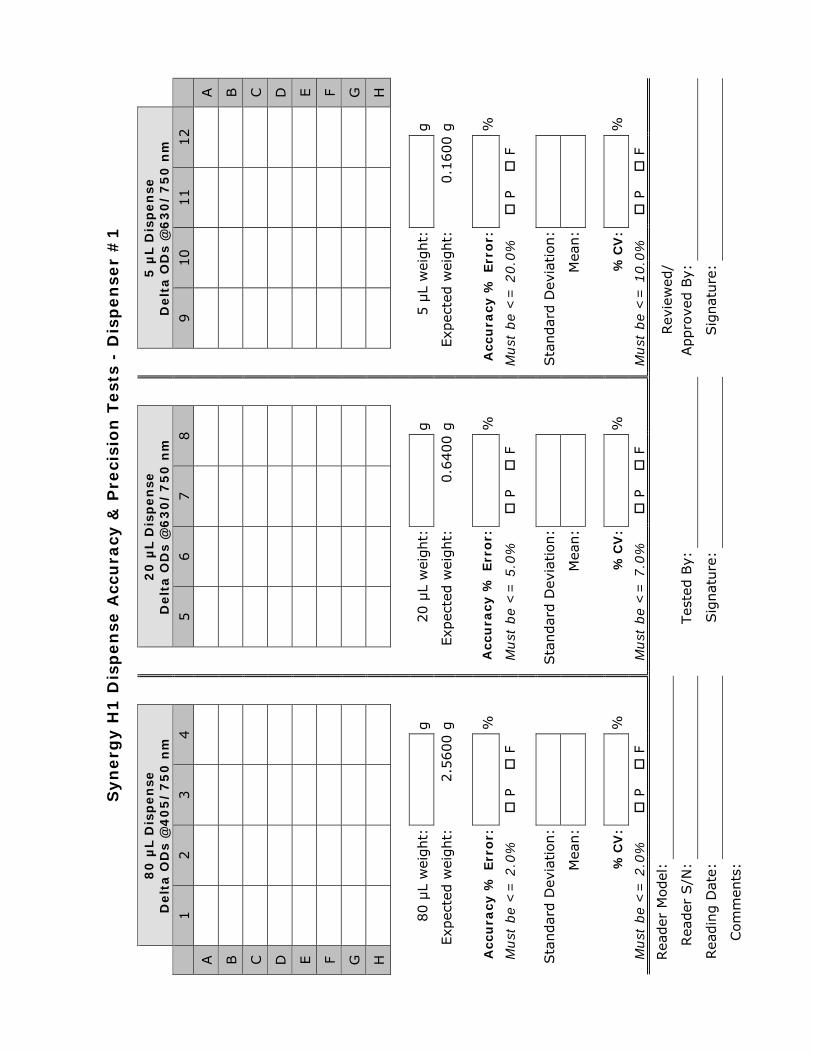
Syn
erg
y H
1 D
isp
en
se A
ccu
racy
& P
reci
sio
n T
est
s -
Dis
pen
ser
#1
8
0 µ
L D
isp
en
se
Delt
a O
Ds
@4
05
/7
50
nm
2
0 µ
L D
isp
en
se
Delt
a O
Ds
@6
30
/7
50
nm
5
µL D
isp
en
se
Delt
a O
Ds
@6
30
/7
50
nm
1
2
3
4
5
6
7
8
9
10
11
12
A
A
B
B
C
C
D
D
E
E
F
F
G
G
H
H
80 µ
L w
eight:
g
20 µ
L w
eight:
g
5 µ
L w
eight:
g
Exp
ecte
d w
eight:
2.5
600 g
Exp
ecte
d w
eight:
0.6
400 g
Exp
ecte
d w
eight:
0.1
600 g
Acc
ura
cy %
Err
or:
%
Acc
ura
cy %
Err
or:
%
Acc
ura
cy %
Err
or:
%
Must
be
<=
2.0
%
P
F
M
ust
be
<=
5.0
%
P
F
M
ust
be
<=
20.0
%
P
F
Sta
ndar
d D
evia
tion:
Sta
ndar
d D
evia
tion:
Sta
ndar
d D
evia
tion:
Mea
n:
Mea
n:
Mea
n:
%C
V:
%
%
CV
: %
%C
V:
%
Must
be
<=
2.0
%
P
F
M
ust
be
<=
7.0
%
P
F
M
ust
be
<=
10.0
%
P
F
Rea
der
Model
:
Tes
ted B
y:
Rev
iew
ed/
Appro
ved B
y:
Rea
der
S/N
:
Rea
din
g D
ate:
Sig
nat
ure
:
Sig
nat
ure
:
Com
men
ts:
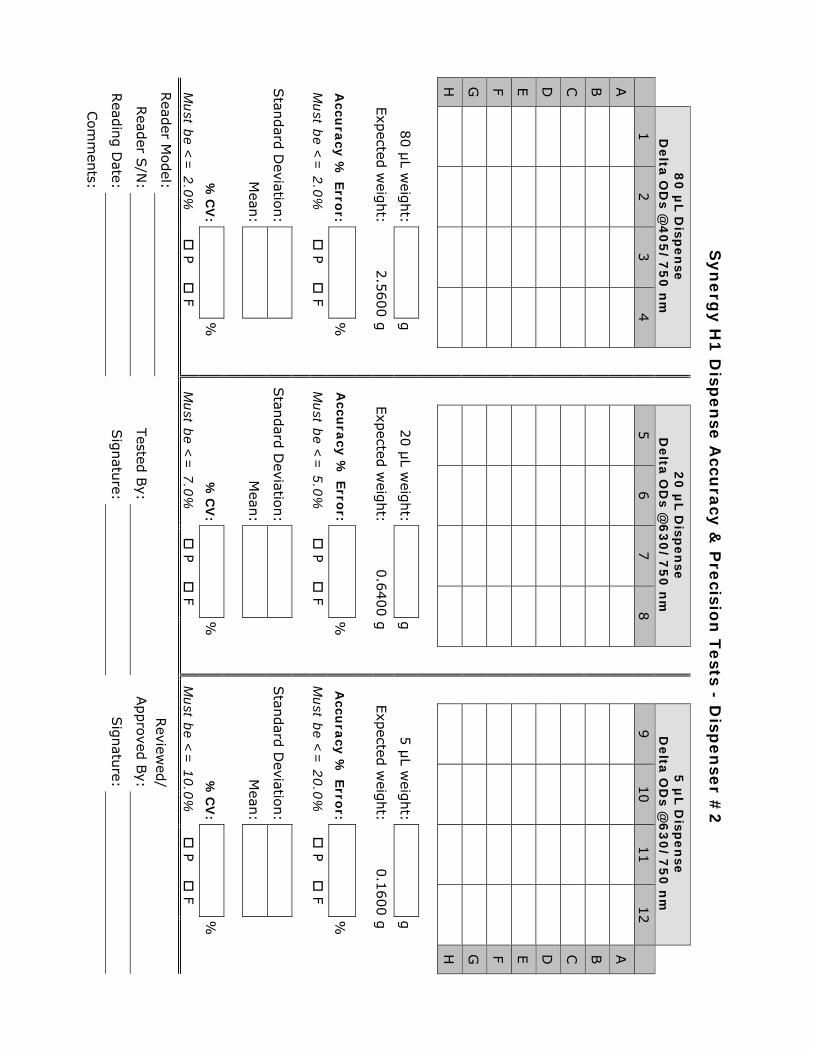
Syn
erg
y H
1 D
ispen
se A
ccura
cy &
Pre
cision
Tests - D
ispen
ser #
2
8
0 µ
L D
ispen
se
Delta
OD
s @4
05
/7
50
nm
2
0 µ
L D
ispen
se
Delta
OD
s @6
30
/7
50
nm
5
µL D
ispen
se
Delta
OD
s @6
30
/7
50
nm
1
2
3
4
5
6
7
8
9
10
11
12
A
A
B
B
C
C
D
D
E
E
F
F
G
G
H
H
80 µ
L weig
ht:
g
2
0 µ
L weig
ht:
g
5
µL w
eight:
g
Exp
ected w
eight:
2.5
600 g
Exp
ected w
eight:
0.6
400 g
Exp
ected w
eight:
0.1
600 g
Accu
racy
% E
rror:
%
A
ccura
cy %
Erro
r: %
Accu
racy
% E
rror:
%
Must b
e <=
2.0
%
P F
M
ust b
e <=
5.0
%
P F
M
ust b
e <=
20.0
%
P F
Stan
dard
Deviatio
n:
Stan
dard
Deviatio
n:
Stan
dard
Deviatio
n:
Mean
:
M
ean:
Mean
:
%C
V:
%
%
CV
: %
%C
V:
%
Must b
e <=
2.0
%
P F
M
ust b
e <=
7.0
%
P F
M
ust b
e <=
10.0
%
P F
Read
er Model:
Tested
By:
Review
ed/
Appro
ved B
y:
Read
er S/N
:
Read
ing D
ate: Sig
natu
re: Sig
natu
re:
Com
men
ts:

Appendix A
Specifications
This appendix contains BioTek’s published specifications for the Synergy H1.
General Specifications .......................................................... 140 Absorbance Specifications .................................................... 141 Dispense/Read Specifications ................................................ 142 Fluorescence Specifications (Mono-Based) .............................. 142 Fluorescence Specifications (Filter-Based) ............................... 143 Luminescence Specifications ................................................. 144
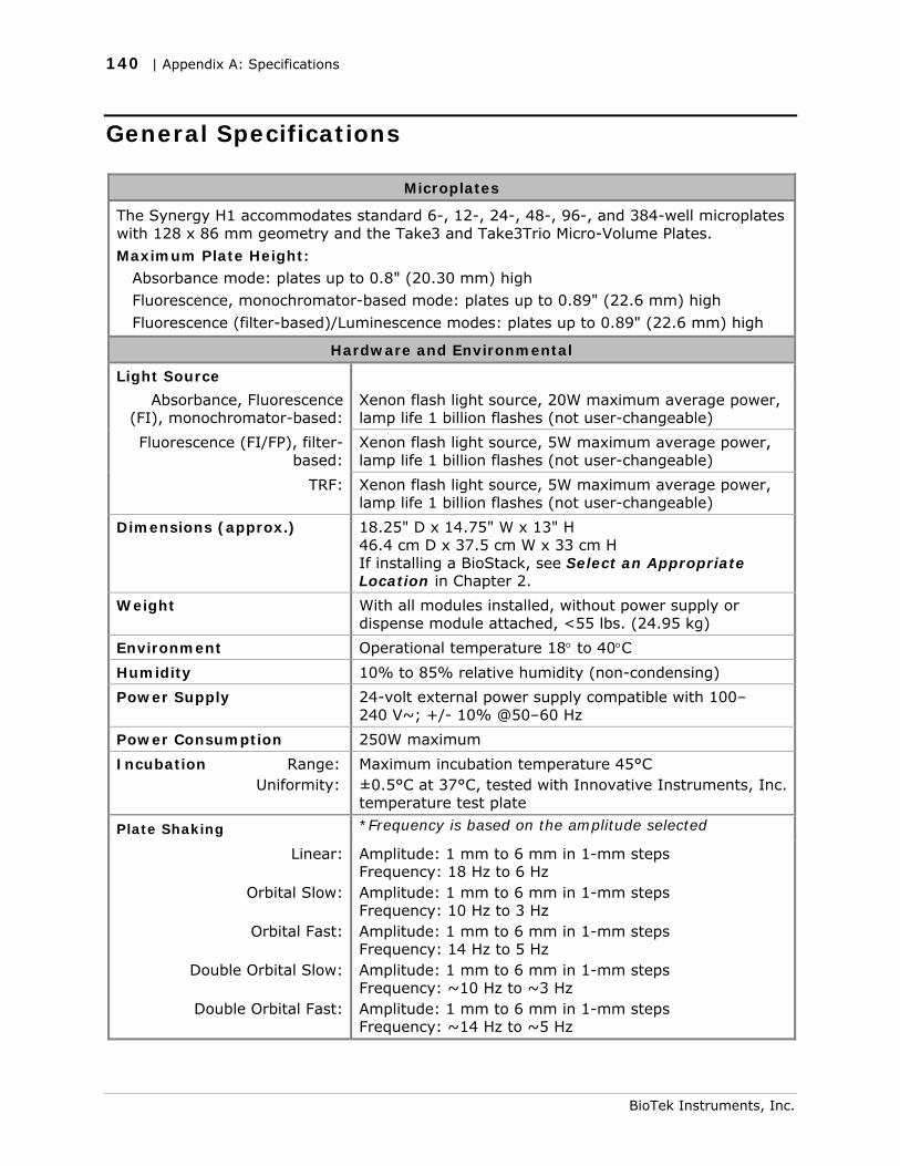
140 | Appendix A: Specifications
General Specifications
Microplates
The Synergy H1 accommodates standard 6-, 12-, 24-, 48-, 96-, and 384-well microplates with 128 x 86 mm geometry and the Take3 and Take3Trio Micro-Volume Plates.
Maximum Plate Height:
Absorbance mode: plates up to 0.8" (20.30 mm) high
Fluorescence, monochromator-based mode: plates up to 0.89" (22.6 mm) high
Fluorescence (filter-based)/Luminescence modes: plates up to 0.89" (22.6 mm) high
Hardware and Environmental
Light Source
Absorbance, Fluorescence (FI), monochromator-based:
Xenon flash light source, 20W maximum average power, lamp life 1 billion flashes (not user-changeable)
Fluorescence (FI/FP), filter-based:
Xenon flash light source, 5W maximum average power, lamp life 1 billion flashes (not user-changeable)
TRF: Xenon flash light source, 5W maximum average power, lamp life 1 billion flashes (not user-changeable)
Dimensions (approx.) 18.25" D x 14.75" W x 13" H 46.4 cm D x 37.5 cm W x 33 cm H If installing a BioStack, see Select an Appropriate Location in Chapter 2.
Weight With all modules installed, without power supply or dispense module attached, <55 lbs. (24.95 kg)
Environment Operational temperature 18° to 40°C
Humidity 10% to 85% relative humidity (non-condensing)
Power Supply 24-volt external power supply compatible with 100– 240 V~; +/- 10% @50–60 Hz
Power Consumption 250W maximum
Incubation Range: Uniformity:
Maximum incubation temperature 45°C ±0.5°C at 37°C, tested with Innovative Instruments, Inc. temperature test plate
Plate Shaking *Frequency is based on the amplitude selected
Linear:
Orbital Slow:
Orbital Fast:
Double Orbital Slow:
Double Orbital Fast:
Amplitude: 1 mm to 6 mm in 1-mm steps Frequency: 18 Hz to 6 Hz Amplitude: 1 mm to 6 mm in 1-mm steps Frequency: 10 Hz to 3 Hz Amplitude: 1 mm to 6 mm in 1-mm steps Frequency: 14 Hz to 5 Hz Amplitude: 1 mm to 6 mm in 1-mm steps Frequency: ~10 Hz to ~3 Hz Amplitude: 1 mm to 6 mm in 1-mm steps Frequency: ~14 Hz to ~5 Hz
BioTek Instruments, Inc.
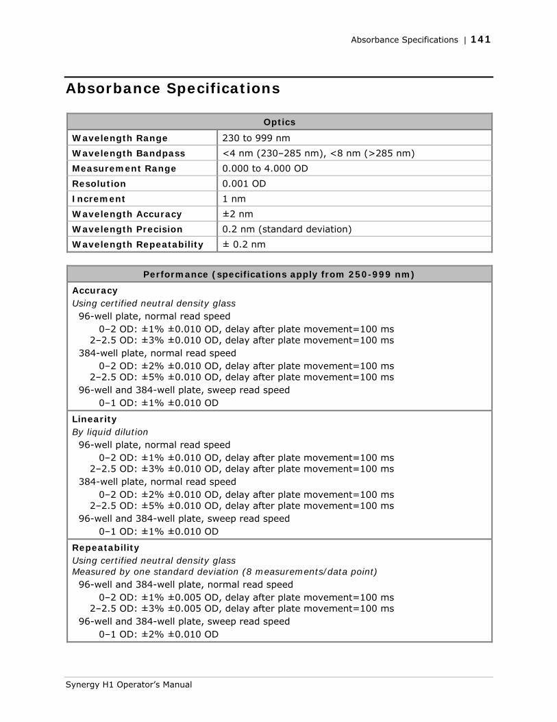
Absorbance Specifications | 141
Absorbance Specifications
Optics
Wavelength Range 230 to 999 nm
Wavelength Bandpass <4 nm (230–285 nm), <8 nm (>285 nm)
Measurement Range 0.000 to 4.000 OD
Resolution 0.001 OD
Increment 1 nm
Wavelength Accuracy ±2 nm
Wavelength Precision 0.2 nm (standard deviation)
Wavelength Repeatability ± 0.2 nm
Performance (specifications apply from 250-999 nm)
Accuracy Using certified neutral density glass 96-well plate, normal read speed 0–2 OD: ±1% ±0.010 OD, delay after plate movement=100 ms 2–2.5 OD: ±3% ±0.010 OD, delay after plate movement=100 ms 384-well plate, normal read speed 0–2 OD: ±2% ±0.010 OD, delay after plate movement=100 ms 2–2.5 OD: ±5% ±0.010 OD, delay after plate movement=100 ms 96-well and 384-well plate, sweep read speed 0–1 OD: ±1% ±0.010 OD
Linearity By liquid dilution 96-well plate, normal read speed 0–2 OD: ±1% ±0.010 OD, delay after plate movement=100 ms 2–2.5 OD: ±3% ±0.010 OD, delay after plate movement=100 ms 384-well plate, normal read speed 0–2 OD: ±2% ±0.010 OD, delay after plate movement=100 ms 2–2.5 OD: ±5% ±0.010 OD, delay after plate movement=100 ms 96-well and 384-well plate, sweep read speed 0–1 OD: ±1% ±0.010 OD
Repeatability Using certified neutral density glass Measured by one standard deviation (8 measurements/data point) 96-well and 384-well plate, normal read speed 0–2 OD: ±1% ±0.005 OD, delay after plate movement=100 ms 2–2.5 OD: ±3% ±0.005 OD, delay after plate movement=100 ms 96-well and 384-well plate, sweep read speed 0–1 OD: ±2% ±0.010 OD
Synergy H1 Operator’s Manual
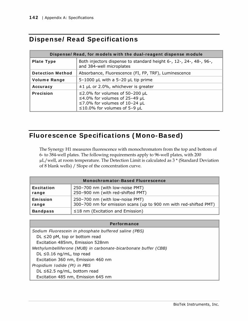
142 | Appendix A: Specifications
Dispense/Read Specifications
Dispense/Read, for models with the dual-reagent dispense module
Plate Type Both injectors dispense to standard height 6-, 12-, 24-, 48-, 96-, and 384-well microplates
Detection Method Absorbance, Fluorescence (FI, FP, TRF), Luminescence
Volume Range 5–1000 µL with a 5–20 µL tip prime
Accuracy ±1 µL or 2.0%, whichever is greater
Precision ≤2.0% for volumes of 50–200 µL ≤4.0% for volumes of 25–49 µL ≤7.0% for volumes of 10–24 µL ≤10.0% for volumes of 5–9 µL
Fluorescence Specifications (Mono-Based)
The Synergy H1 measures fluorescence with monochromators from the top and bottom of 6- to 384-well plates. The following requirements apply to 96-well plates, with 200 µL/well, at room temperature. The Detection Limit is calculated as 3 * (Standard Deviation of 8 blank wells) / Slope of the concentration curve.
Monochromator-Based Fluorescence
Excitation range
250–700 nm (with low-noise PMT) 250–900 nm (with red-shifted PMT)
Emission range
250–700 nm (with low-noise PMT) 300–700 nm for emission scans (up to 900 nm with red-shifted PMT)
Bandpass ≤18 nm (Excitation and Emission)
Performance
Sodium Fluorescein in phosphate buffered saline (PBS) DL ≤20 pM, top or bottom read Excitation 485nm, Emission 528nm Methylumbelliferone (MUB) in carbonate-bicarbonate buffer (CBB) DL ≤0.16 ng/mL, top read Excitation 360 nm, Emission 460 nm Propidium Iodide (PI) in PBS DL ≤62.5 ng/mL, bottom read Excitation 485 nm, Emission 645 nm
BioTek Instruments, Inc.
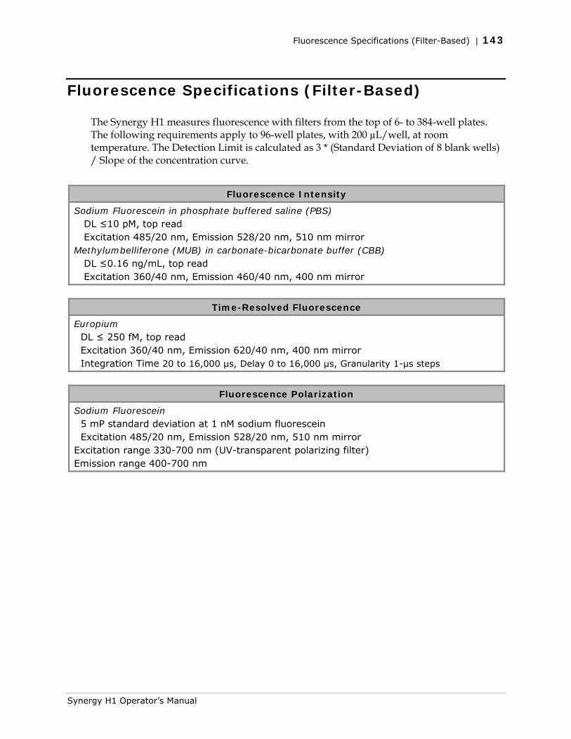
Fluorescence Specifications (Filter-Based) | 143
Fluorescence Specifications (Filter-Based)
The Synergy H1 measures fluorescence with filters from the top of 6- to 384-well plates. The following requirements apply to 96-well plates, with 200 µL/well, at room temperature. The Detection Limit is calculated as 3 * (Standard Deviation of 8 blank wells) / Slope of the concentration curve.
Fluorescence Intensity
Sodium Fluorescein in phosphate buffered saline (PBS) DL ≤10 pM, top read Excitation 485/20 nm, Emission 528/20 nm, 510 nm mirror Methylumbelliferone (MUB) in carbonate-bicarbonate buffer (CBB) DL ≤0.16 ng/mL, top read Excitation 360/40 nm, Emission 460/40 nm, 400 nm mirror
Time-Resolved Fluorescence
Europium DL ≤ 250 fM, top read Excitation 360/40 nm, Emission 620/40 nm, 400 nm mirror Integration Time 20 to 16,000 µs, Delay 0 to 16,000 µs, Granularity 1-µs steps
Fluorescence Polarization
Sodium Fluorescein 5 mP standard deviation at 1 nM sodium fluorescein Excitation 485/20 nm, Emission 528/20 nm, 510 nm mirror Excitation range 330-700 nm (UV-transparent polarizing filter) Emission range 400-700 nm
Synergy H1 Operator’s Manual
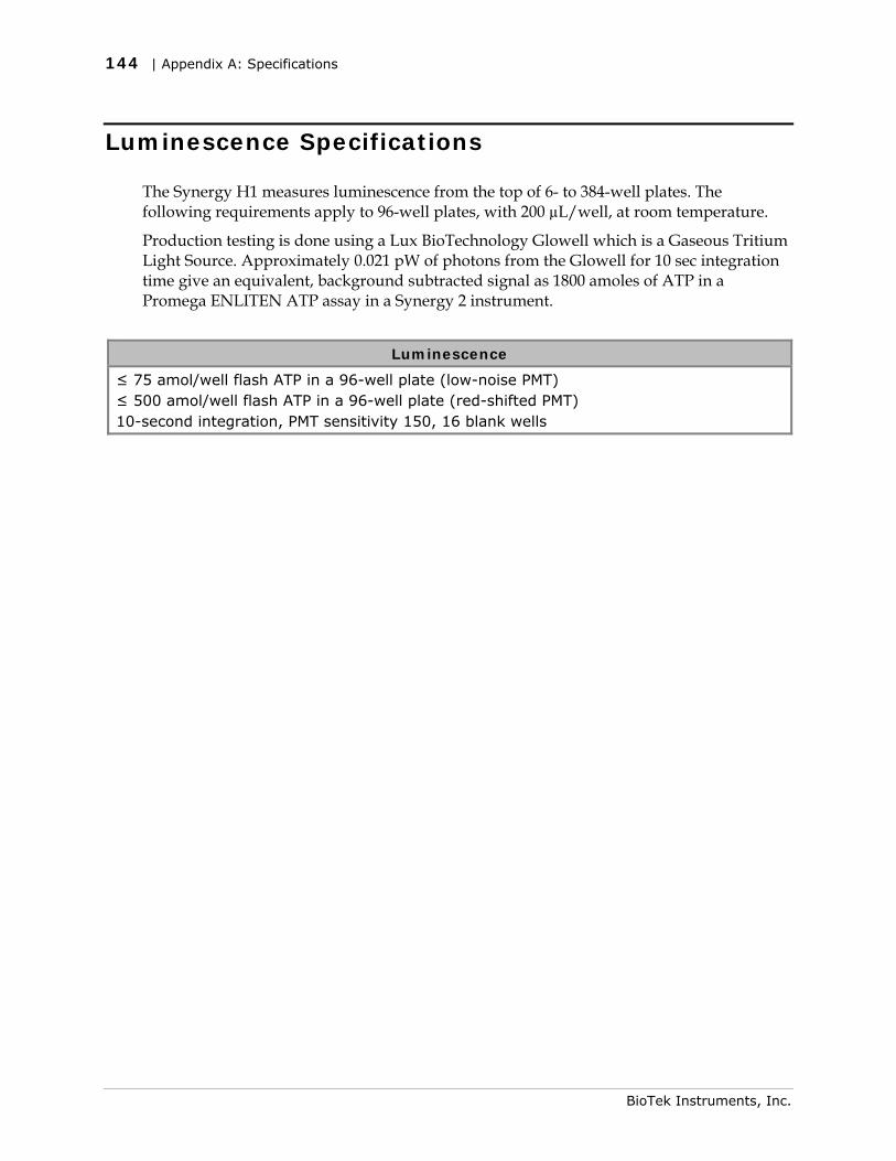
144 | Appendix A: Specifications
BioTek Instruments, Inc.
Luminescence Specifications
The Synergy H1 measures luminescence from the top of 6- to 384-well plates. The following requirements apply to 96-well plates, with 200 µL/well, at room temperature.
Production testing is done using a Lux BioTechnology Glowell which is a Gaseous Tritium Light Source. Approximately 0.021 pW of photons from the Glowell for 10 sec integration time give an equivalent, background subtracted signal as 1800 amoles of ATP in a Promega ENLITEN ATP assay in a Synergy 2 instrument.
Luminescence
≤ 75 amol/well flash ATP in a 96-well plate (low-noise PMT) ≤ 500 amol/well flash ATP in a 96-well plate (red-shifted PMT) 10-second integration, PMT sensitivity 150, 16 blank wells
Appendix B
Error Codes
This appendix lists and describes Synergy H1 error codes that may appear in Gen5.
Overview ........................................................................... 146 Contact Info: BioTek Service/TAC ..................................... 146
Error Codes ........................................................................ 147
146 | Appendix B: Error Codes
Overview
When a problem occurs during operation with the Synergy H1, an error code appears in Gen5. Error codes typically contain four characters, such as “4168,” and in most cases are accompanied by descriptive text, such as “PMT overload error.” With many errors, the instrument will beep repeatedly; press the carrier eject button to stop this alarm.
Some problems can be solved easily, such as “2B0A: Priming plate not detected” (place a priming plate on the carrier). Some problems can be solved only by trained BioTek service personnel. This appendix lists the most common and easily resolved error codes that you may encounter.
Error codes beginning with “A” (e.g., A100) indicate conditions that require immediate attention. If this type of code appears, turn the instrument off and on. If the System Test does not conclude successfully, record the error code and contact BioTek’s Technical Assistance Center.
If an error code appears in Gen5, you may want to run a System Test for diagnostic purposes. In Gen5, select System > Diagnostics > Run System Test.
If an error message appears while an experiment is in process and after having received measurement data, it is your responsibility to determine if the data is valid.
Contact Info: BioTek Service/TAC
Use this appendix to diagnose problems and solve them if possible. If you need further assistance, contact BioTek’s Technical Assistance Center.
Phone: 800-242-4685 (toll free in the U.S.) 802-655-4740 (outside the U.S.)
Fax: 802-654-0638
E-Mail: [email protected]
For errors that are displayed during operation of the Synergy H1 with the BioStack Microplate Stacker, refer to the BioStack Operator’s Manual.
BioTek Instruments, Inc.
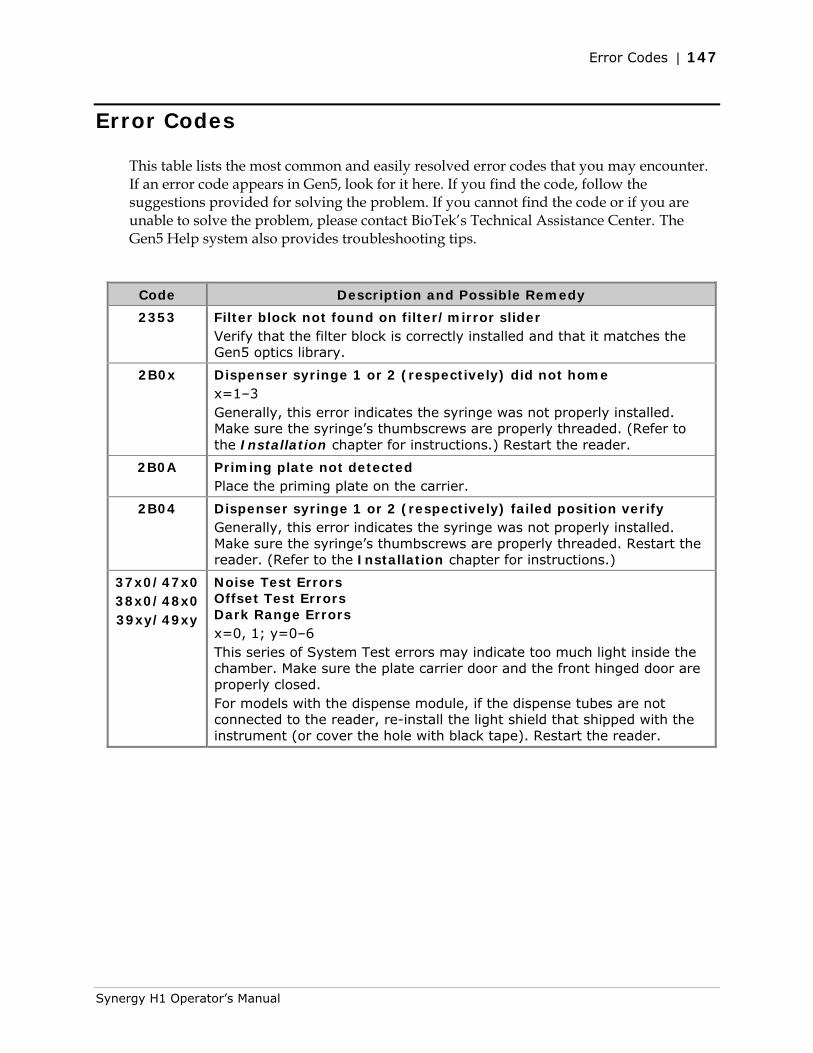
Error Codes | 147
Error Codes
This table lists the most common and easily resolved error codes that you may encounter. If an error code appears in Gen5, look for it here. If you find the code, follow the suggestions provided for solving the problem. If you cannot find the code or if you are unable to solve the problem, please contact BioTek’s Technical Assistance Center. The Gen5 Help system also provides troubleshooting tips.
Code Description and Possible Remedy
2353
Filter block not found on filter/mirror slider Verify that the filter block is correctly installed and that it matches the Gen5 optics library.
2B0x Dispenser syringe 1 or 2 (respectively) did not home x=1–3 Generally, this error indicates the syringe was not properly installed. Make sure the syringe’s thumbscrews are properly threaded. (Refer to the Installation chapter for instructions.) Restart the reader.
2B0A Priming plate not detected Place the priming plate on the carrier.
2B04 Dispenser syringe 1 or 2 (respectively) failed position verify Generally, this error indicates the syringe was not properly installed. Make sure the syringe’s thumbscrews are properly threaded. Restart the reader. (Refer to the Installation chapter for instructions.)
37x0/47x0 38x0/48x0 39xy/49xy
Noise Test Errors Offset Test Errors Dark Range Errors x=0, 1; y=0–6 This series of System Test errors may indicate too much light inside the chamber. Make sure the plate carrier door and the front hinged door are properly closed. For models with the dispense module, if the dispense tubes are not connected to the reader, re-install the light shield that shipped with the instrument (or cover the hole with black tape). Restart the reader.
Synergy H1 Operator’s Manual
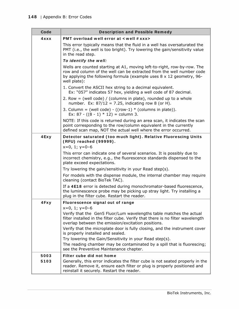
148 | Appendix B: Error Codes
BioTek Instruments, Inc.
Code Description and Possible Remedy
4xxx PMT overload well error at <well #xxx>
This error typically means that the fluid in a well has oversaturated the PMT (i.e., the well is too bright). Try lowering the gain/sensitivity value in the read step.
To identify the well:
Wells are counted starting at A1, moving left-to-right, row-by-row. The row and column of the well can be extracted from the well number code by applying the following formula (example uses 8 x 12 geometry, 96-well plate):
1. Convert the ASCII hex string to a decimal equivalent. Ex: “057” indicates 57 hex, yielding a well code of 87 decimal.
2. Row = (well code) / (columns in plate), rounded up to a whole number. Ex: 87/12 = 7.25, indicating row 8 (or H).
3. Column = (well code) - ((row-1) * (columns in plate)). Ex: 87 - ((8 - 1) * 12) = column 3.
NOTE: If this code is returned during an area scan, it indicates the scan point corresponding to the row/column equivalent in the currently defined scan map, NOT the actual well where the error occurred.
4Exy Detector saturated (too much light). Relative Fluorescing Units (RFU) reached (99999). x=0, 1; y=0–6
This error can indicate one of several scenarios. It is possibly due to incorrect chemistry, e.g., the fluorescence standards dispensed to the plate exceed expectations.
Try lowering the gain/sensitivity in your Read step(s).
For models with the dispense module, the internal chamber may require cleaning (contact BioTek TAC).
If a 4E18 error is detected during monochromator-based fluorescence, the luminescence probe may be picking up stray light. Try installing a plug in the filter cube. Restart the reader.
4Fxy Fluorescence signal out of range x=0, 1; y=0–6 Verify that the Gen5 Fluor/Lum wavelengths table matches the actual filter installed in the filter cube. Verify that there is no filter wavelength overlap between the emission/excitation positions. Verify that the microplate door is fully closing, and the instrument cover is properly installed and sealed. Try lowering the Gain/Sensitivity in your Read step(s). The reading chamber may be contaminated by a spill that is fluorescing; see the Preventive Maintenance chapter.
5003 5103
Filter cube did not home Generally, this error indicates the filter cube is not seated properly in the reader. Remove it, ensure each filter or plug is properly positioned and reinstall it securely. Restart the reader.
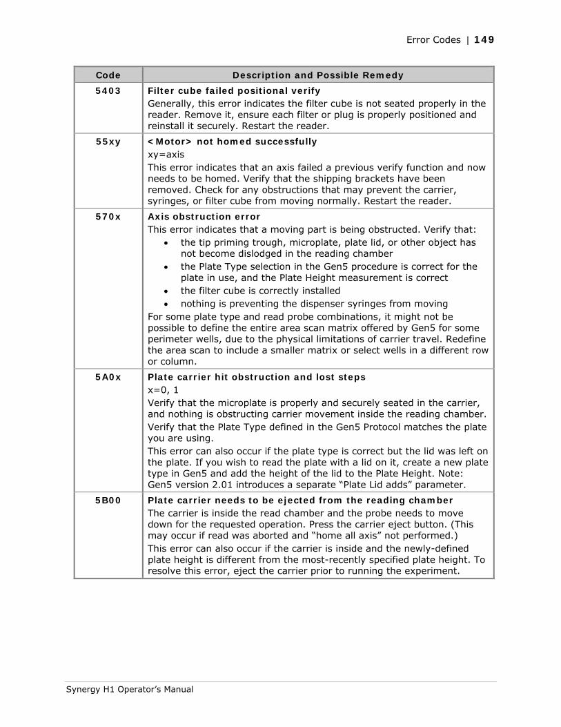
Error Codes | 149
Synergy H1 Operator’s Manual
Code Description and Possible Remedy
5403 Filter cube failed positional verify Generally, this error indicates the filter cube is not seated properly in the reader. Remove it, ensure each filter or plug is properly positioned and reinstall it securely. Restart the reader.
55xy <Motor> not homed successfully xy=axis This error indicates that an axis failed a previous verify function and now needs to be homed. Verify that the shipping brackets have been removed. Check for any obstructions that may prevent the carrier, syringes, or filter cube from moving normally. Restart the reader.
570x Axis obstruction error This error indicates that a moving part is being obstructed. Verify that:
• the tip priming trough, microplate, plate lid, or other object has not become dislodged in the reading chamber
• the Plate Type selection in the Gen5 procedure is correct for the plate in use, and the Plate Height measurement is correct
• the filter cube is correctly installed • nothing is preventing the dispenser syringes from moving
For some plate type and read probe combinations, it might not be possible to define the entire area scan matrix offered by Gen5 for some perimeter wells, due to the physical limitations of carrier travel. Redefine the area scan to include a smaller matrix or select wells in a different row or column.
5A0x Plate carrier hit obstruction and lost steps x=0, 1 Verify that the microplate is properly and securely seated in the carrier, and nothing is obstructing carrier movement inside the reading chamber. Verify that the Plate Type defined in the Gen5 Protocol matches the plate you are using. This error can also occur if the plate type is correct but the lid was left on the plate. If you wish to read the plate with a lid on it, create a new plate type in Gen5 and add the height of the lid to the Plate Height. Note: Gen5 version 2.01 introduces a separate “Plate Lid adds” parameter.
5B00 Plate carrier needs to be ejected from the reading chamber The carrier is inside the read chamber and the probe needs to move down for the requested operation. Press the carrier eject button. (This may occur if read was aborted and “home all axis” not performed.) This error can also occur if the carrier is inside and the newly-defined plate height is different from the most-recently specified plate height. To resolve this error, eject the carrier prior to running the experiment.

150 | Appendix B: Error Codes
BioTek Instruments, Inc.

Appendix C
Instrument Dimensions for Robotic Interface
This section shows the location of the microplate carrier in reference to the exterior surfaces of the Synergy H1 and the mounting holes on the bottom. Use the illustrations to facilitate system setup with a robotic instrument, such as the BioStack Microplate Stacker. Dimensions are in inches.
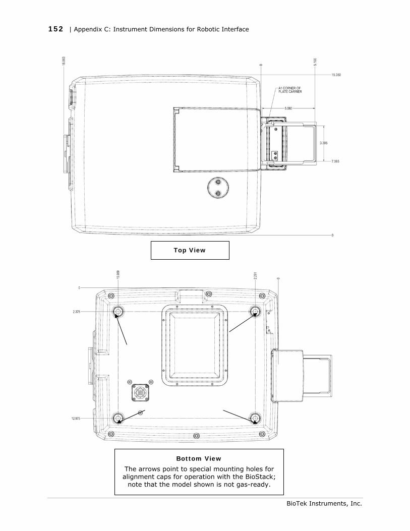
152 | Appendix C: Instrument Dimensions for Robotic Interface
Top View
Bottom View
The arrows point to special mounting holes for alignment caps for operation with the BioStack;
note that the model shown is not gas-ready.
BioTek Instruments, Inc.
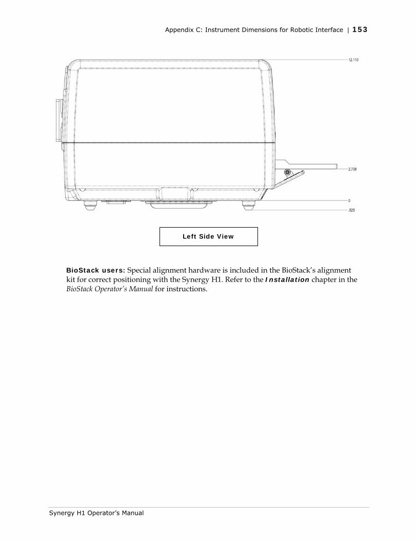
Appendix C: Instrument Dimensions for Robotic Interface | 153
Left Side View
BioStack users: Special alignment hardware is included in the BioStack’s alignment kit for correct positioning with the Synergy H1. Refer to the Installation chapter in the BioStack Operator’s Manual for instructions.
Synergy H1 Operator’s Manual

154 | Appendix C: Instrument Dimensions for Robotic Interface
BioTek Instruments, Inc.

Index
Absorbance Liquid Test 1, 89 Absorbance Liquid Test 2, 92 Absorbance Liquid Test 3, 94 Absorbance Plate Test
sample report, 86 Absorbance Test Plate
defining parameters, 84 didymium glass, 85 holmium glass, 84
absorbance tests. See liquid tests, absorbance
accessories, 4 Applications Support, 6 biohazards, x BioStack
using with Synergy H1, 11, 151 carrier eject button, 17 changing a filter cube, 44 changing filters, 46 changing mirrors, 46 cleaning
exposed surfaces, 54 filters, 55 mirrors, 56
components external, 31 internal, 31
contact BioTek Customer Service, v general, v Sales, v Service, v TAC, v
decontamination alternate procedure for injectors, 69 dispense module, 66 overview, 64 prior to shipping, 22
dispense module about, 34 components, 34 daily cleaning, 52 flushing, 58 installing, 13 maintenance, 52 maintenance schedule, 53 materials composition, 35 prime, 38 purge, 39 purging, 58 replacing a syringe, 70 unpacking, 10
dispense tests accuracy, 127 overview, 127 precision, 127
dispense tubes cleaning, 61 removing, 61
electrical grounding, ix emission filters
introduction, 46 environmental conditions, x error codes
description of, 147 overview, 146

152 | Index
excitation filters introduction, 46
experiments, 37 external components, 31 Failure Mode Effects Analysis, 77 filter cube
adding to library, 44 changing, 44 default configuration, 42 defining, 36 description, 32 installing, 44 overview, 42 removing, 44
Filter Cube Library. See Optics Library filter set setup, 99
luminescence, 120 filters
available from BioTek, 49 changing, 46 cleaning, 55 removing, 46 replacing, 48
fluorescence liquid tests filter set setup, 99 Gen5 protocol parameters, 111, 118 test kit, 100 troubleshooting, 110 using methylumbelliferone, 113
flushing the dispense module, 58 FMEA. See Failure Mode Effects
Analysis FP test
description, 97 gas controller module
about, 2 installing, 13
Gen5 defining filter cube in, 36 experiments, 37 installing, 17 protocols, 37
Glowell, 122 grounding, ix H1F, 30 H1FD, 30 H1FDG, 30
H1FG, 30 H1M, 30 H1MD, 30 H1MDG, 30 H1MF, 30 H1MFD, 30 H1MFDG, 30 H1MFDG, 8 H1MFG, 30 H1MG, 30 Harta Luminometer Reference
Microplate, 120 injector system
overview, 33 priming, 35 test, 19
injectors cleaning, 61 removing, 61
installation, 7 connecting host computer, 16 dispense module, 13 establish communications, 17 gas controller module, 13 installing Gen5, 17 power supply, 12 selecting a location, 11 shipping hardware, 11 unpack the dispense module, 10 unpack the reader, 9
installation qualification, 75 internal components, 31 internal voltage, ix liquid tests
absorbance, 89 luminescence measurements
setup, 32 luminescence tests
filter set setup, 120 Glowell, 122 Harta plate, 120 overview, 120 protocol parameters, 123 troubleshooting, 126
maintenance schedule, 53
methylumbelliferone fluorescence tests
BioTek Instruments, Inc.

Index | 153
Operator’s Manual
overview, 113 protocol parameters, 118
mirrors available from BioTek, 50 changing, 46 cleaning, 56 overview, 33 removing, 46 replacing, 48
modules, 30 MUB. See methylumbelliferone
fluorescence tests operational qualification, 76 Optics Library, 44
adding filter cube, 44 part numbers, 30 performance qualification, 76 polarizers, 43 power supply, 12 preventive maintenance
dispense module, 52 overview, 52
priming plate cleaning, 60
priming the injector system, 35 product qualification package, 75 product registration, viii protocol parameters
fluorescence, 111, 118 luminescence, 123
protocols, 37 purging the dispense module, 58 qualification
description, 75 schedule, 76
reader dimensions, 151 remove a filter, 46 remove a mirror, 46 removing a filter cube, 44 repackaging the reader, 21 replace a filter, 48
replace a mirror, 48 serial port/cable (RS-232), 16 shipping hardware, 11 shipping the reader, 21 specifications
absorbance, 141 dispense, 142 environment, 140 filter-based fluorescence, 143 general, 140 hardware, 140 luminescence, 144 microplates, 140 mono-based fluorescence, 142
spilled fluids, ix Support
Applications, 6 syringe
replacing, 70 System Test, 18
automatic, 77 failure, 78 initiate a, 77 sample report, 83
TAC. See Technical Assistance Center Technical Assistance Center (TAC), 6 temperature control, 2 test communication, 17 tip priming trough
cleaning, 60 emptying, 60
TRF test description, 97
unpack the dispense module, 10 unpack the reader, 9 USB cable
about, 16 installing driver, 17
voltage, ix warnings, viii warranty, viii

154 | Index
BioTek Instruments, Inc.