Embed Size (px)
Citation preview
Synthetic Aperture Radar Modeling using MATLAB and Simulink
Naivedya Mishra
Team Lead
Uurmi Systems Pvt. Ltd. Hyderabad
Agenda
• What is Synthetic Aperture Radar?
• SAR Imaging Process
• Challenges in Design and Simulation
• Modeling in MATLAB
• System Block Diagram
• Algorithm Flow
• Modeling in Simulink
• Key modules involved
• Conversion Simulink-HDL
• Major modules involved
• SimRF Model for Raw Data Generation
• Results and Discussions
• Simulator GUI Snapshots
• Other Results 2
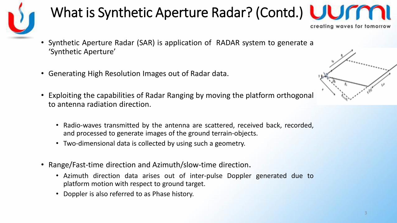
• Synthetic Aperture Radar (SAR) is application of RADAR system to generate a‘Synthetic Aperture’
• Generating High Resolution Images out of Radar data.
• Exploiting the capabilities of Radar Ranging by moving the platform orthogonalto antenna radiation direction.
• Radio-waves transmitted by the antenna are scattered, received back, recorded,and processed to generate images of the ground terrain-objects.
• Two-dimensional data is collected by using such a geometry.
• Range/Fast-time direction and Azimuth/slow-time direction.• Azimuth direction data arises out of inter-pulse Doppler generated due to
platform motion with respect to ground target.
• Doppler is also referred to as Phase history.
3
What is Synthetic Aperture Radar? (Contd.)
What is Synthetic Aperture Radar? (Contd.)
• Range and azimuth data are processed to generate SAR image
• Advantages of Synthetic Aperture Radar
• Key advantage being an active sensor system.
• All-Weather Performance, Independent of atmospheric conditions (day, night, fog, rain etc.).
• Foliage Penetration for certain operating Frequencies.
• Long range operation (~200 meters up to few hundred kilometers).
• High resolution imaging (1 meter at orbital altitude of ~500Kms).
4
SAR Imaging Process
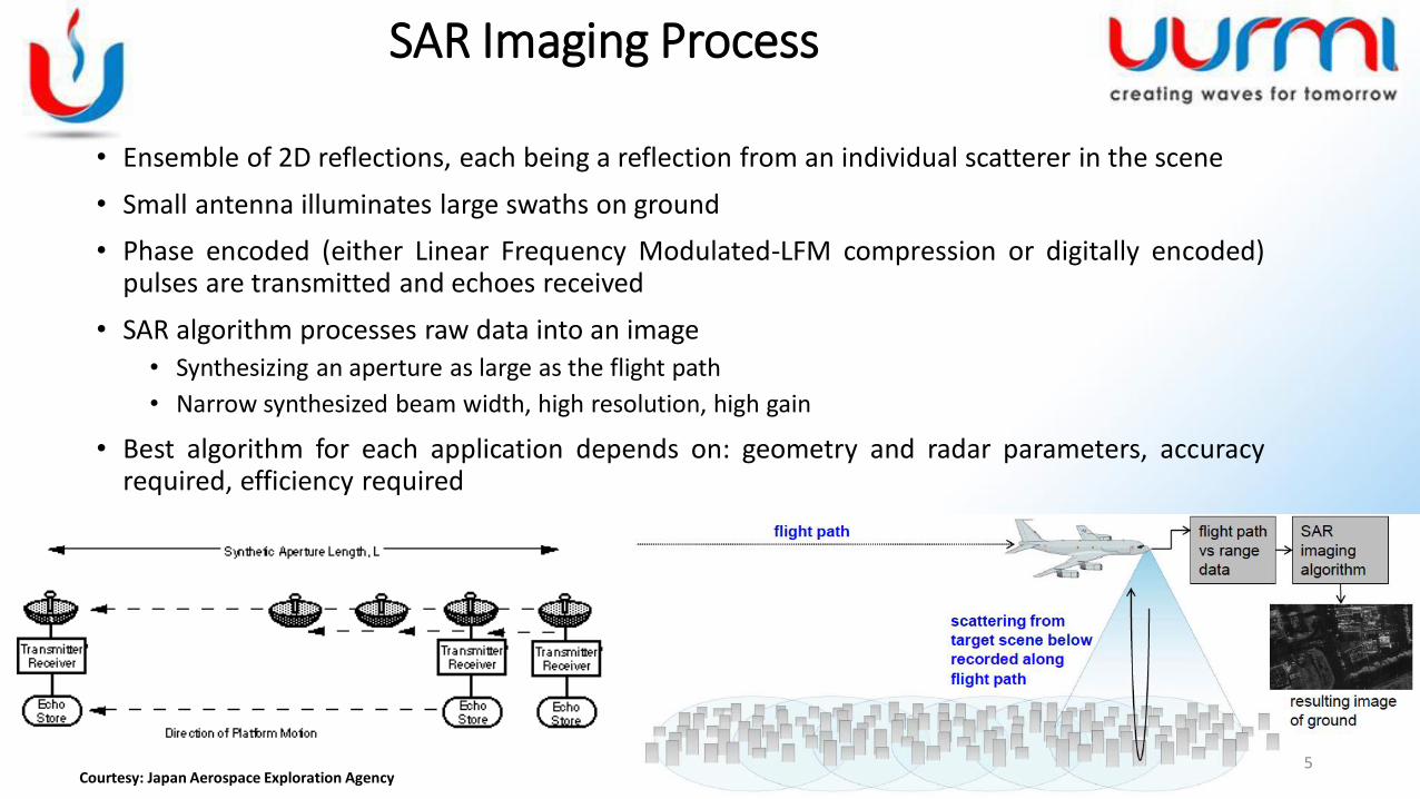
• Ensemble of 2D reflections, each being a reflection from an individual scatterer in the scene
• Small antenna illuminates large swaths on ground
• Phase encoded (either Linear Frequency Modulated-LFM compression or digitally encoded)pulses are transmitted and echoes received
• SAR algorithm processes raw data into an image
• Synthesizing an aperture as large as the flight path
• Narrow synthesized beam width, high resolution, high gain
• Best algorithm for each application depends on: geometry and radar parameters, accuracyrequired, efficiency required
5Courtesy: Japan Aerospace Exploration Agency
• The problem is primarily a System development problem
• The problem includes
• Proof of Concept development• Signal Processing Algorithm development • Hardware(RF + Baseband Processing)
• Most of the solutions focus on specific targets either RF or Baseband
• The fundamental advantage MATLAB provides is an end-to-end simulation and design of the system.
• Looking at fundamental implementation level, a simple example can be datatype.
6
Challenges in Design and Simulation
• The ease MATLAB provides in including equations, generating data pertaining to the equations helps ease the entire chain.
• The typical chain of any prototype development has simulation as its very prominent component.
• Especially, in design of radar systems where the cost of hardware implementation is very high.
• MATLAB provides a platform wherein the entire simulation can be performed in short time.
7
Challenges in Design and Simulation
Modeling in MATLAB
• Entire development can be summarized into 2 parts• Simulator Development to generate SAR Raw Data
• Processing Algorithm Development to process the Raw Data generated from the Simulator
• Simulator development involves:• Transmit waveform design and description
• Platform trajectory description
• Target description
• Platform motion and echo return capturing
• Processing Algorithm Development• Involves carrier removal
• Range Processing
• Motion compensation(optional/depending on requirement)
• Squint Angle Correction(optional/depending on requirement)
• Azimuth Processing8
9
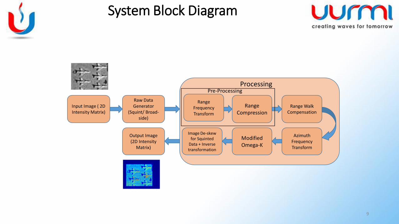
Input Image ( 2D Intensity Matrix)
Raw Data Generator
(Squint/ Broad-side)
Range Walk Compensation
Modified Omega-K
Processing
Range Compression
Image De-skew for Squinted
Data + Inverse transformation
Range Frequency Transform
Azimuth Frequency Transform
Output Image (2D Intensity
Matrix)
Pre-Processing
System Block Diagram
10
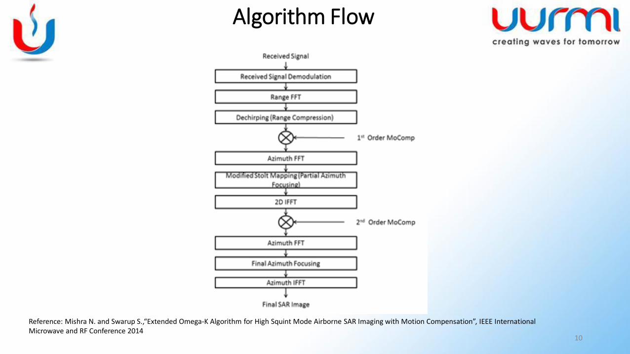
Algorithm Flow
Reference: Mishra N. and Swarup S.,“Extended Omega-K Algorithm for High Squint Mode Airborne SAR Imaging with Motion Compensation”, IEEE International Microwave and RF Conference 2014
11
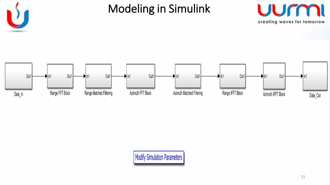
Modeling in Simulink
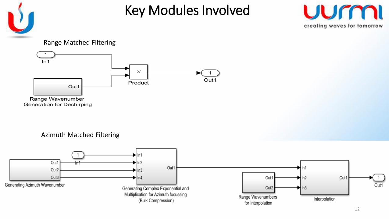
Range Matched Filtering
Azimuth Matched Filtering
12
Key Modules Involved
13
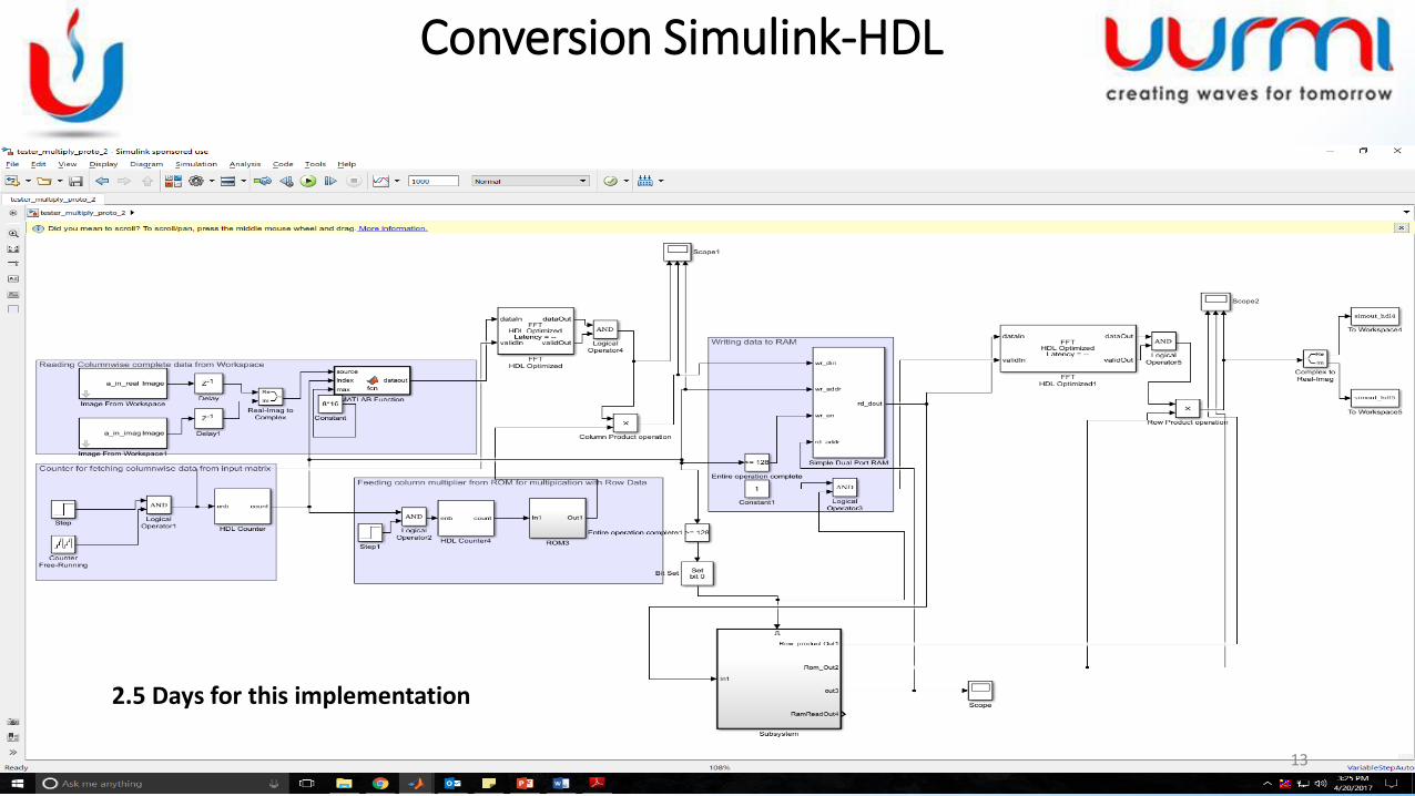
Conversion Simulink-HDL
2.5 Days for this implementation
14
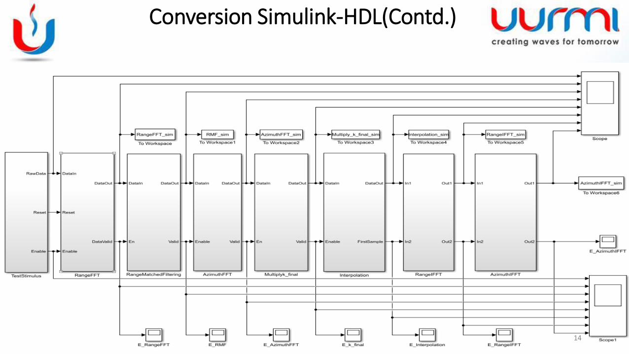
Conversion Simulink-HDL(Contd.)
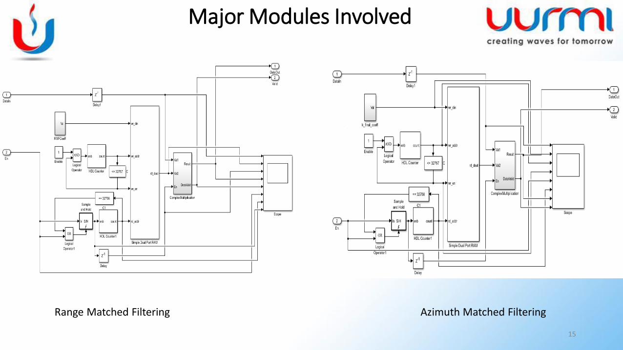
Range Matched Filtering Azimuth Matched Filtering
15
Major Modules Involved
16
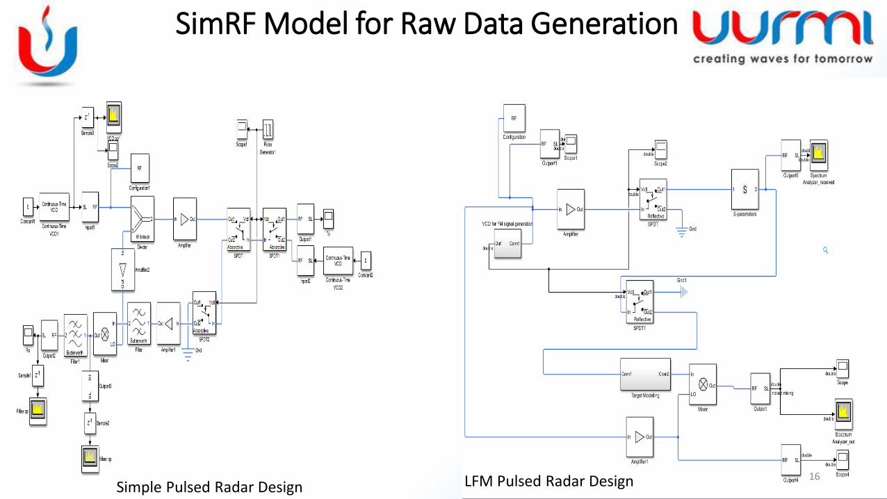
SimRF Model for Raw Data Generation
Simple Pulsed Radar Design LFM Pulsed Radar Design
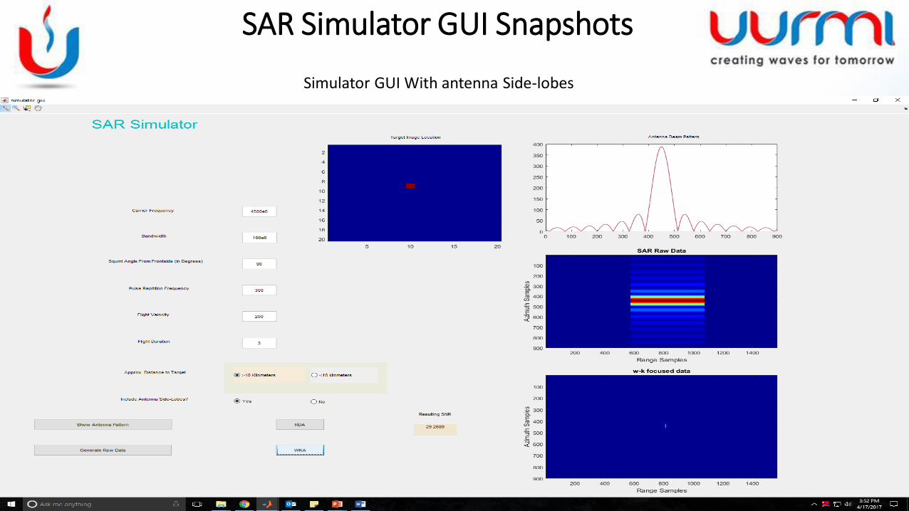
SAR Simulator GUI Snapshots
17
Simulator GUI With antenna Side-lobes
18
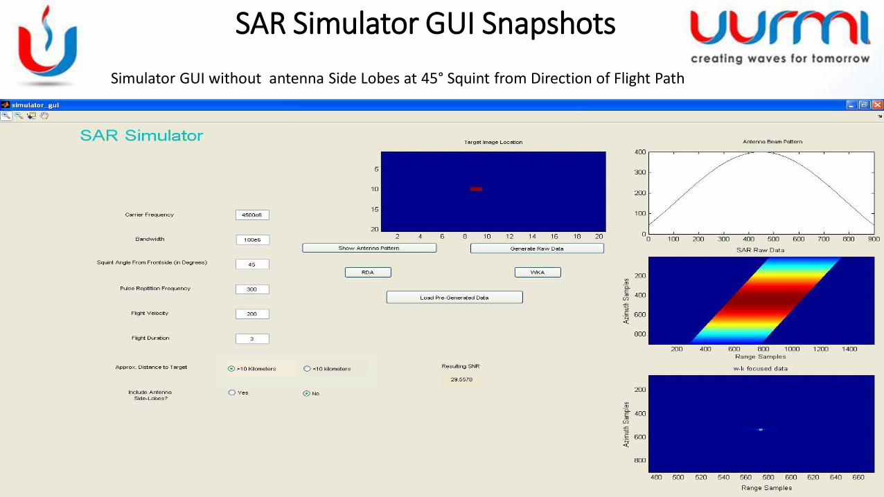
Simulator GUI without antenna Side Lobes at 45° Squint from Direction of Flight Path
SAR Simulator GUI Snapshots
19
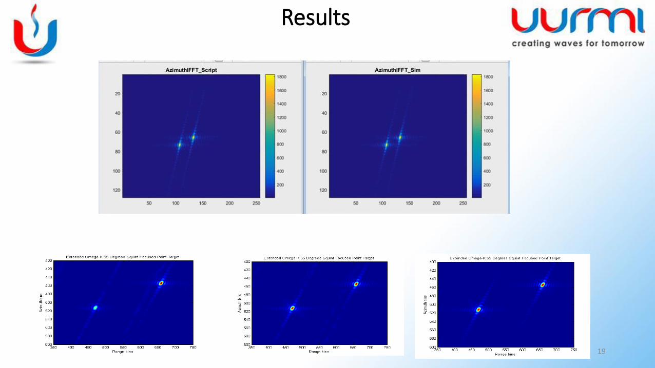
Results
20
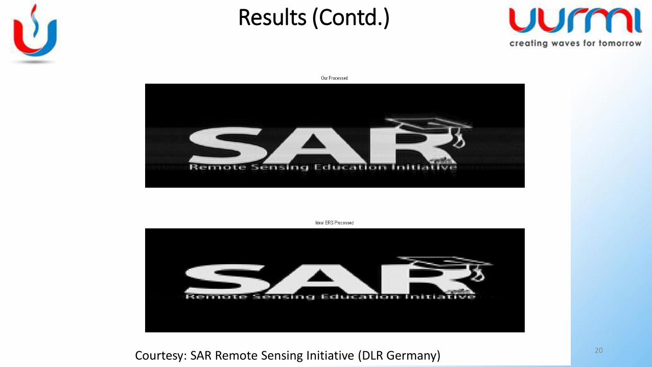
Results (Contd.)
Courtesy: SAR Remote Sensing Initiative (DLR Germany)
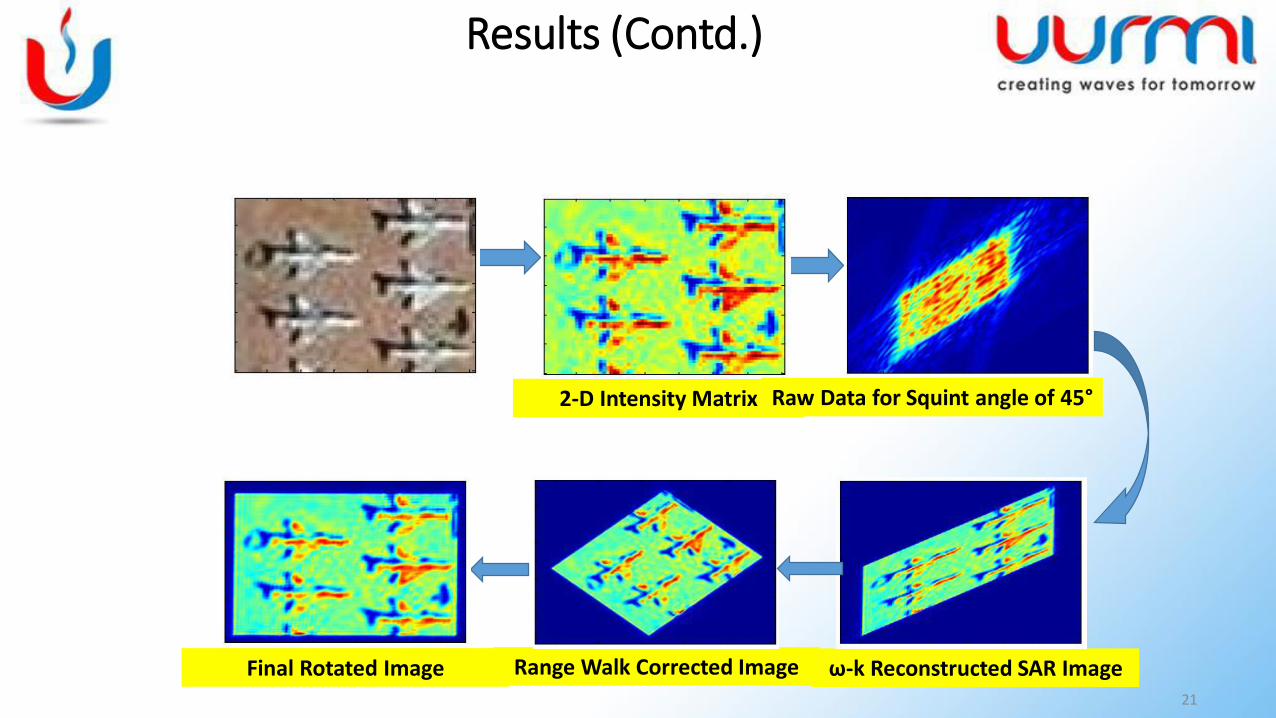
21
2-D Intensity Matrix
Range Walk Corrected Image ω-k Reconstructed SAR ImageFinal Rotated Image
Raw Data for Squint angle of 45°
Results (Contd.)
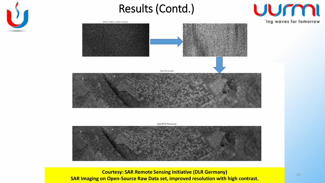
Courtesy: SAR Remote Sensing Initiative (DLR Germany)SAR Imaging on Open-Source Raw Data set, improved resolution with high contrast.
22
Results (Contd.)
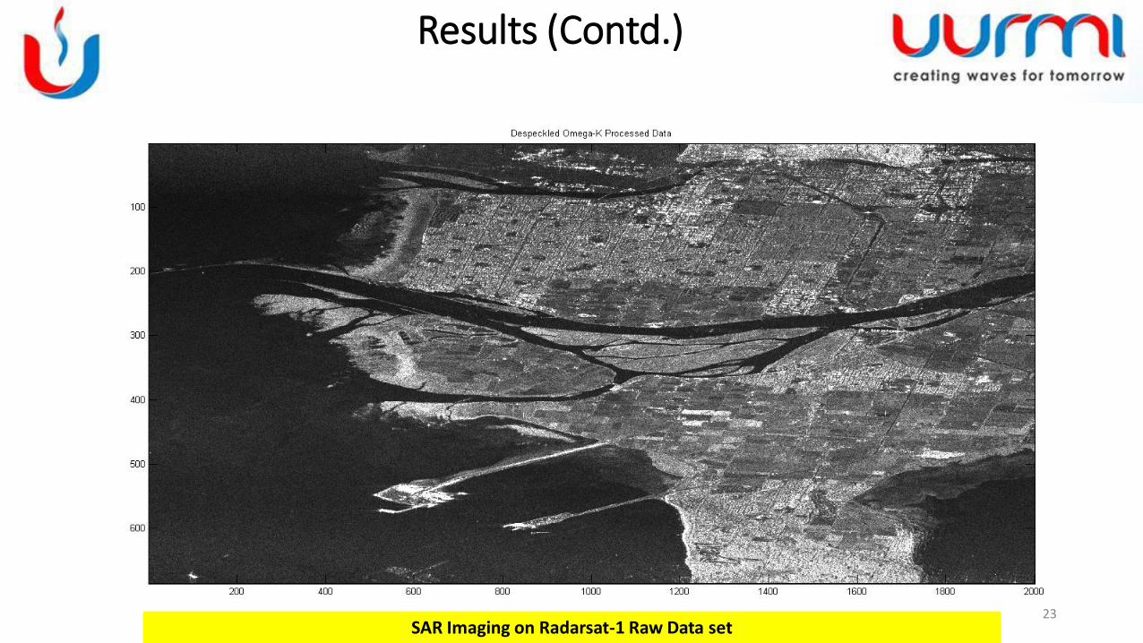
SAR Imaging on Radarsat-1 Raw Data set23
Results (Contd.)
• Mishra N. and Swarup S.,“Extended Omega-K Algorithm for High Squint Mode Airborne SAR Imaging with Motion Compensation”, IEEE International Microwave and RF Conference 2014
• Vandewal M. et.al., “Efficient and Precise Processing for Squinted Spotlight SAR through a Modified Stolt Mapping”, EURASIP Journal on Advances in Signal Processing 2007.
• Nguyen M.P., “Second Order Motion Compensation for Squinted Spotlight Synthetic Aperture Radar”, Asia-Pacific Conference on Synthetic Aperture Radar 2013(APSAR).
• Cumming I.G., Wong F.H.,“Digital Processing of Synthetic Aperture Radar Data: Algorithms and Implementation”,Artech House, 2004.
• MATLAB-Simulink Documentation
24
References