Embed Size (px)
Citation preview
1System Analysis and Design
Data Flow Diagram
System Analysis and Design
2 System Analysis and Design
Data Flow diagram
• The dataflow diagram is a modeling tool that allows us to picture a system as a network of functional processes, connected to one another by “pipelines” and “holding tanks” of data
3 System Analysis and Design
Data Flow Diagrams
• Context Diagrams– Top-level view of an information system that
shows the system’s boundaries and scope
– Do not show any data stores in a context diagram because data stores are internal to the system.
– Begin by reviewing the system requirements to
identify all external data sources and destinations
4 System Analysis and Design
Context Diagrams
– Record the name of the entities and the name and content of the data flows, and the direction of the data flows.
– What makes one system more complex than another is the number of components, the number of levels, and the degree of interaction among its processes, entities, data stores, and data flows
System Analysis and DesignSlide 5
• Shows the overall business process as just one process.
• The process is given the number zero.
• Shows all the outside entities that receive information from or contribute information to the system
Context Diagrams
6 System Analysis and Design
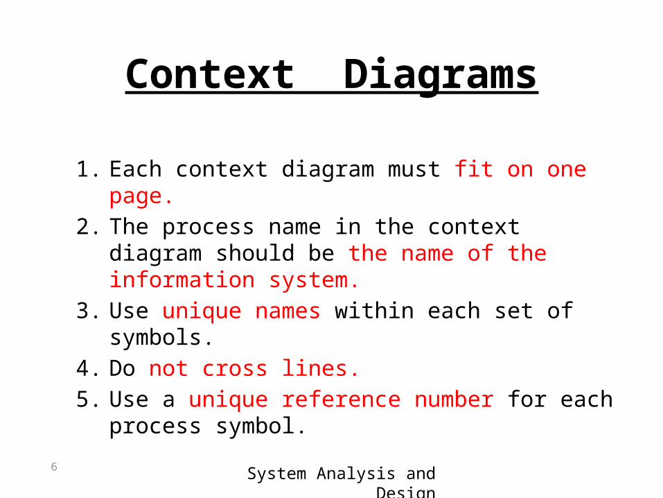
1. Each context diagram must fit on one page.2. The process name in the context diagram
should be the name of the information system.3. Use unique names within each set of symbols.4. Do not cross lines.5. Use a unique reference number for each
process symbol.
Context Diagrams

7 System Analysis and Design
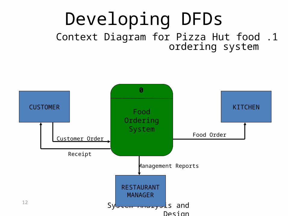
Developing DFDs1 .Context Diagram for Pizza Hut food ordering
system
CUSTOMER KITCHEN
RESTAURANTMANAGER
FoodOrderingSystem
0
Customer Order
Receipt
Food Order
Management Reports
System Analysis and Design
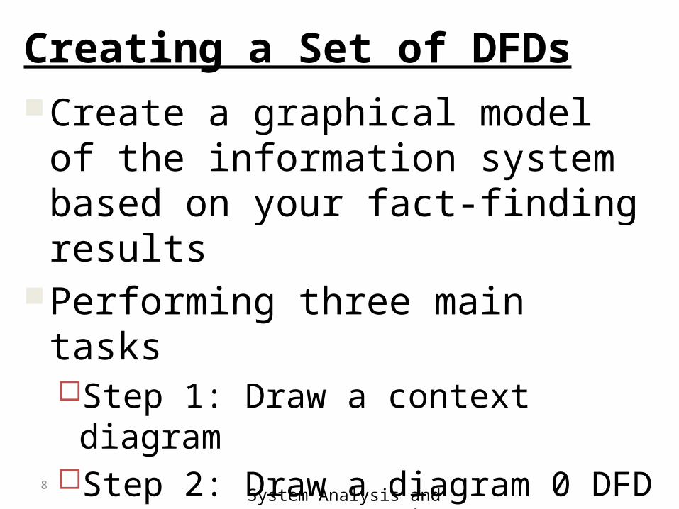
Creating a Set of DFDsCreate a graphical model of the
information system based on your fact-finding results
Performing three main tasksStep 1: Draw a context diagramStep 2: Draw a diagram 0 DFDStep 3: Draw the lower-level diagrams
8
System Analysis and Design
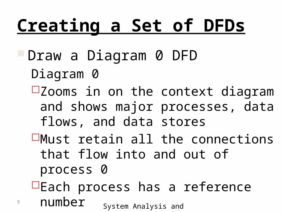
Creating a Set of DFDs Draw a Diagram 0 DFD
Diagram 0Zooms in on the context diagram and shows
major processes, data flows, and data storesMust retain all the connections that flow into
and out of process 0Each process has a reference numberDiverging data flow
9
System Analysis and Design
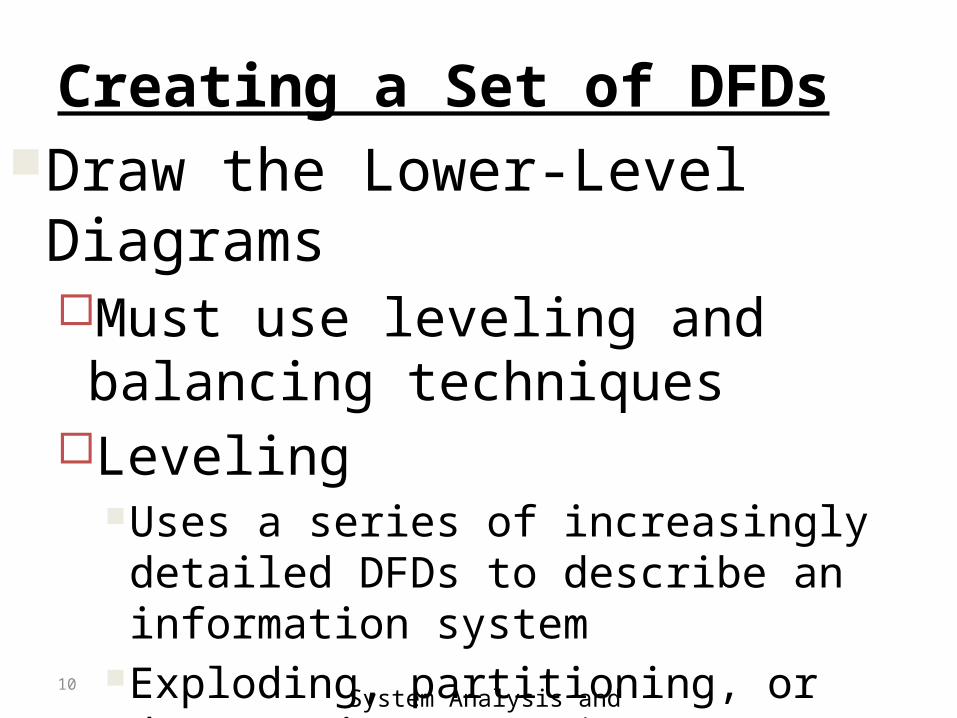
Creating a Set of DFDsDraw the Lower-Level Diagrams
Must use leveling and balancing techniques
LevelingUses a series of increasingly detailed DFDs to
describe an information systemExploding, partitioning, or decomposing
10
System Analysis and Design
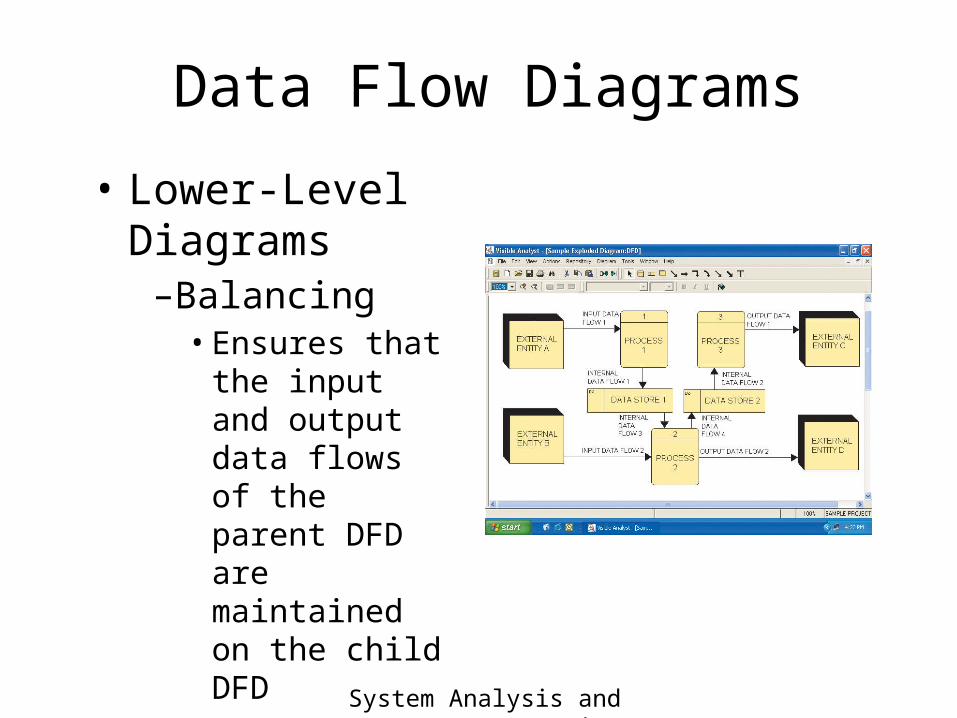
Data Flow Diagrams
• Lower-Level Diagrams–Balancing• Ensures that the
input and output data flows of the parent DFD are maintained on the child DFD
12 System Analysis and Design
Developing DFDs1 .Context Diagram for Pizza Hut food ordering
system
CUSTOMER KITCHEN
RESTAURANTMANAGER
FoodOrderingSystem
0
Customer Order
Receipt
Food Order
Management Reports
13 System Analysis and Design
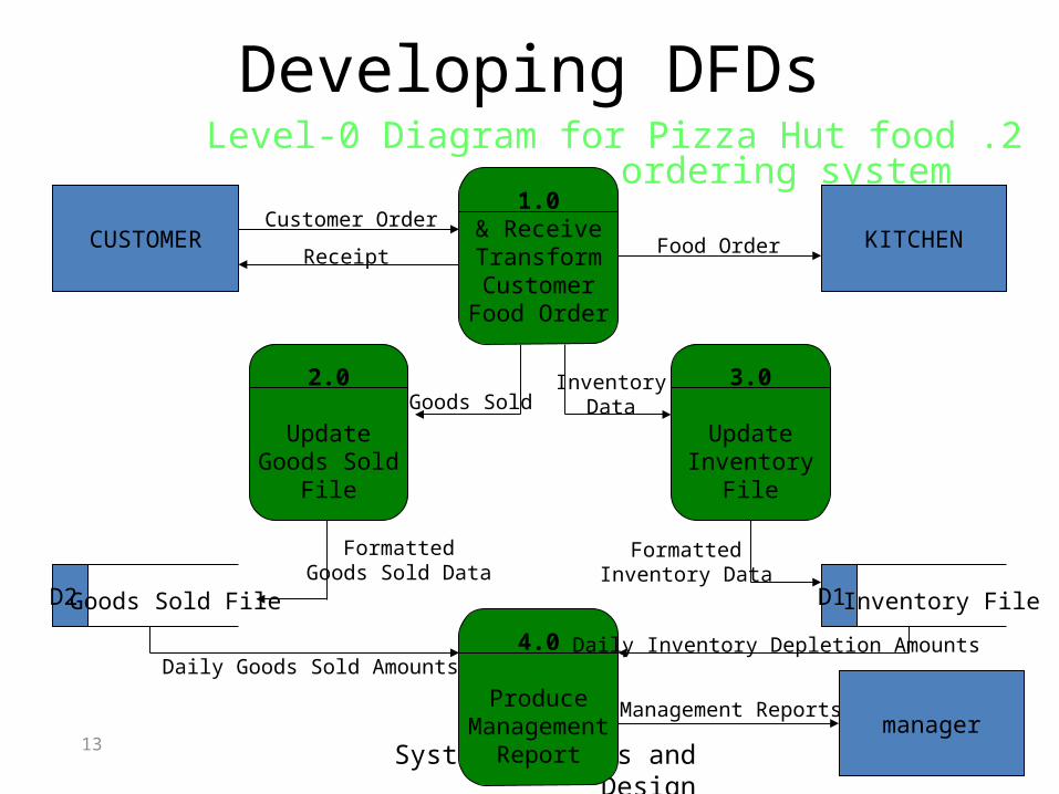
Developing DFDs2 .Level-0 Diagram for Pizza Hut food ordering
system
CUSTOMER KITCHEN
manager
1.0Receive &
TransformCustomer
Food Order
3.0
UpdateInventory
File
2.0
UpdateGoods Sold
File
D1 Inventory File D2 Goods Sold File
4.0
ProduceManagement
Report
Customer Order
Receipt Food Order
InventoryDataGoods Sold
FormattedInventory Data
FormattedGoods Sold Data
Daily Goods Sold AmountsDaily Inventory Depletion Amounts
Management Reports
14 System Analysis and Design
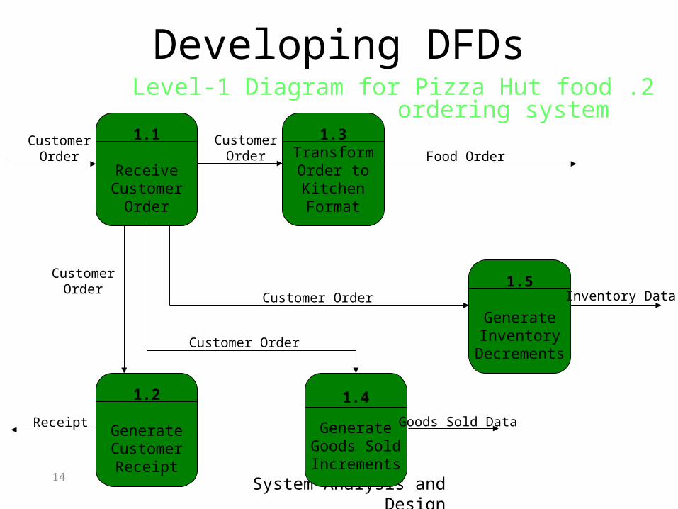
Developing DFDs2 .Level-1 Diagram for Pizza Hut food ordering
system1.1
ReceiveCustomer
Order
1.3TransformOrder toKitchenFormat
1.2
GenerateCustomerReceipt
1.4
GenerateGoods SoldIncrements
1.5
GenerateInventory
Decrements
CustomerOrder
CustomerOrder Food Order
CustomerOrder
Customer Order
Customer Order Inventory Data
Goods Sold DataReceipt
15System Analysis and Design
Rules Governing Data Flow Diagramming
16 System Analysis and Design
Rules Governing Data Flow Diagramming Process
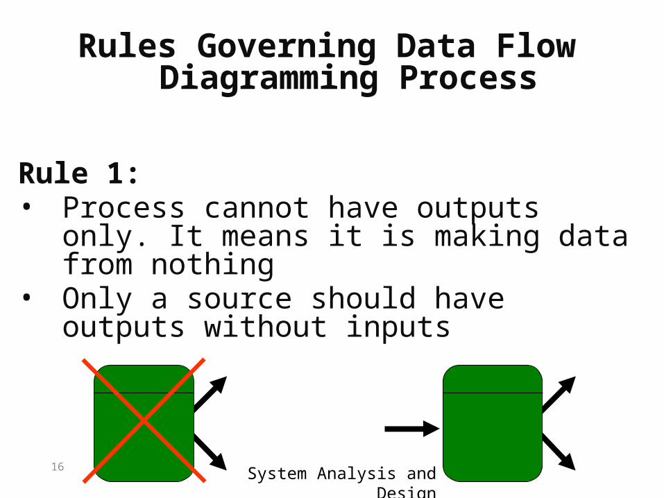
Rule 1:• Process cannot have outputs only. It
means it is making data from nothing• Only a source should have outputs
without inputs
17 System Analysis and Design
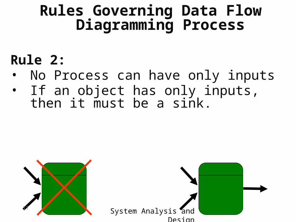
Rule 2:• No Process can have only inputs• If an object has only inputs, then it
must be a sink.
Rules Governing Data Flow Diagramming Process
18 System Analysis and Design
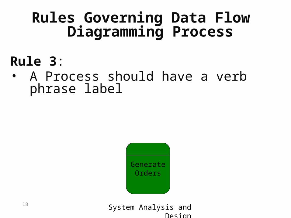
Rule 3:• A Process should have a verb phrase
label
GenerateOrders
Rules Governing Data Flow Diagramming Process
19 System Analysis and Design
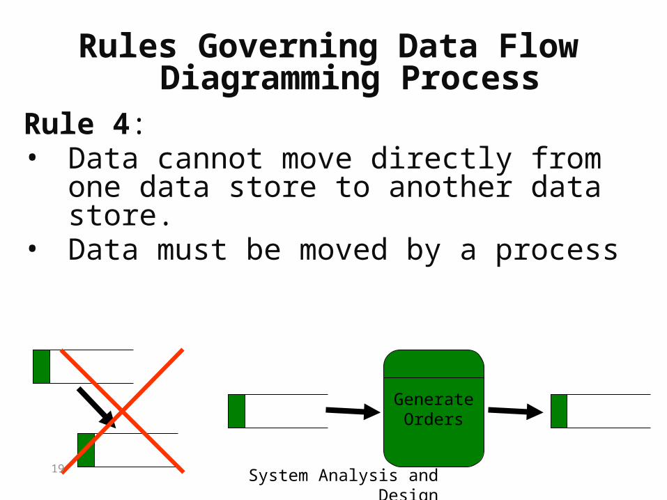
Rule 4:• Data cannot move directly from one
data store to another data store.• Data must be moved by a process
GenerateOrders
Rules Governing Data Flow Diagramming Process
20 System Analysis and Design
Rules Governing Data Flow Diagramming Process
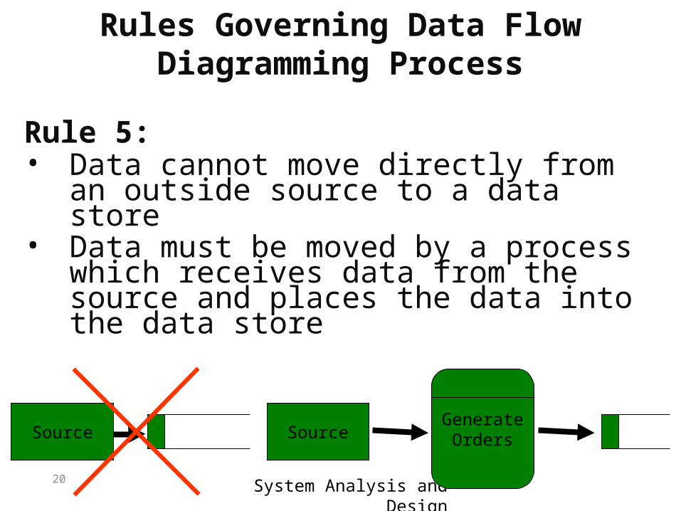
Rule 5:• Data cannot move directly from an
outside source to a data store• Data must be moved by a process
which receives data from the source and places the data into the data store
GenerateOrdersSource Source
21 System Analysis and Design
Rules Governing Data Flow Diagramming Process
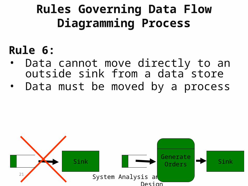
Rule 6:• Data cannot move directly to an
outside sink from a data store• Data must be moved by a process
GenerateOrders SinkSink
22 System Analysis and Design
Rules Governing Data Flow Diagramming Process
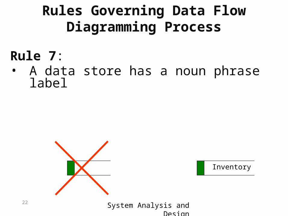
Rule 7:• A data store has a noun phrase label
Inventory
23 System Analysis and Design
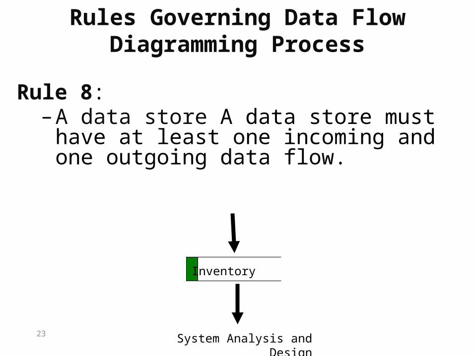
Rules Governing Data Flow Diagramming Process
Rule 8:–A data store A data store must have at least
one incoming and one outgoing data flow.
Inventory
24 System Analysis and Design
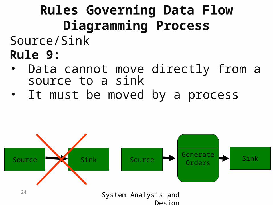
Rules Governing Data Flow Diagramming Process
Source/SinkRule 9:• Data cannot move directly from a
source to a sink• It must be moved by a process
SinkSource Source SinkGenerateOrders
25 System Analysis and Design
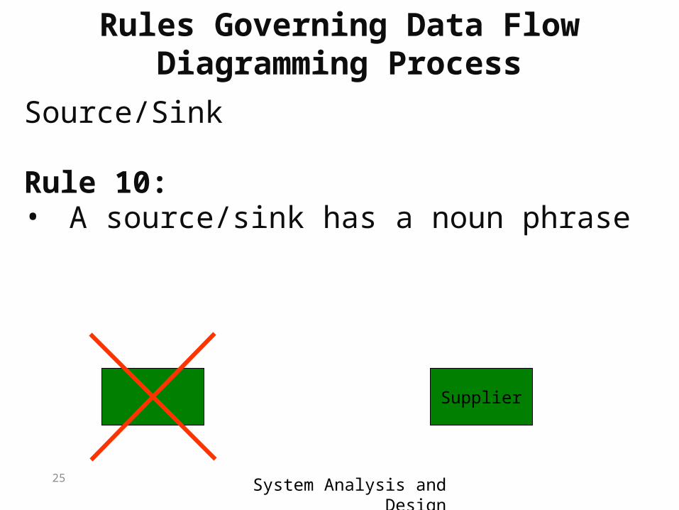
Rules Governing Data Flow Diagramming Process
Source/Sink
Rule 10:• A source/sink has a noun phrase
Supplier
26 System Analysis and Design
Rules Governing Data Flow Diagramming Process
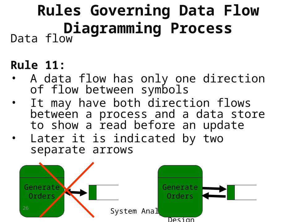
Data flow
Rule 11:• A data flow has only one direction of flow
between symbols• It may have both direction flows between a
process and a data store to show a read before an update
• Later it is indicated by two separate arrows
GenerateOrders
GenerateOrders
27 System Analysis and Design
Rules Governing Data Flow Diagramming Process
Data flow
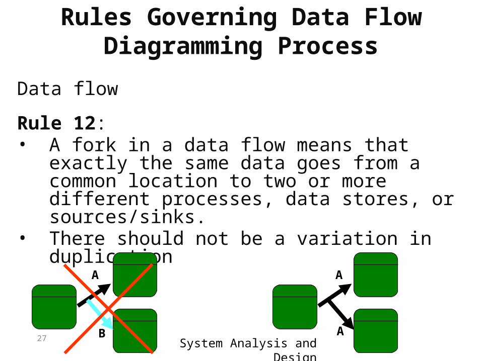
Rule 12:• A fork in a data flow means that exactly the
same data goes from a common location to two or more different processes, data stores, or sources/sinks.
• There should not be a variation in duplication
A
B
A
A
28 System Analysis and Design
Rules Governing Data Flow Diagramming Process
Data flow
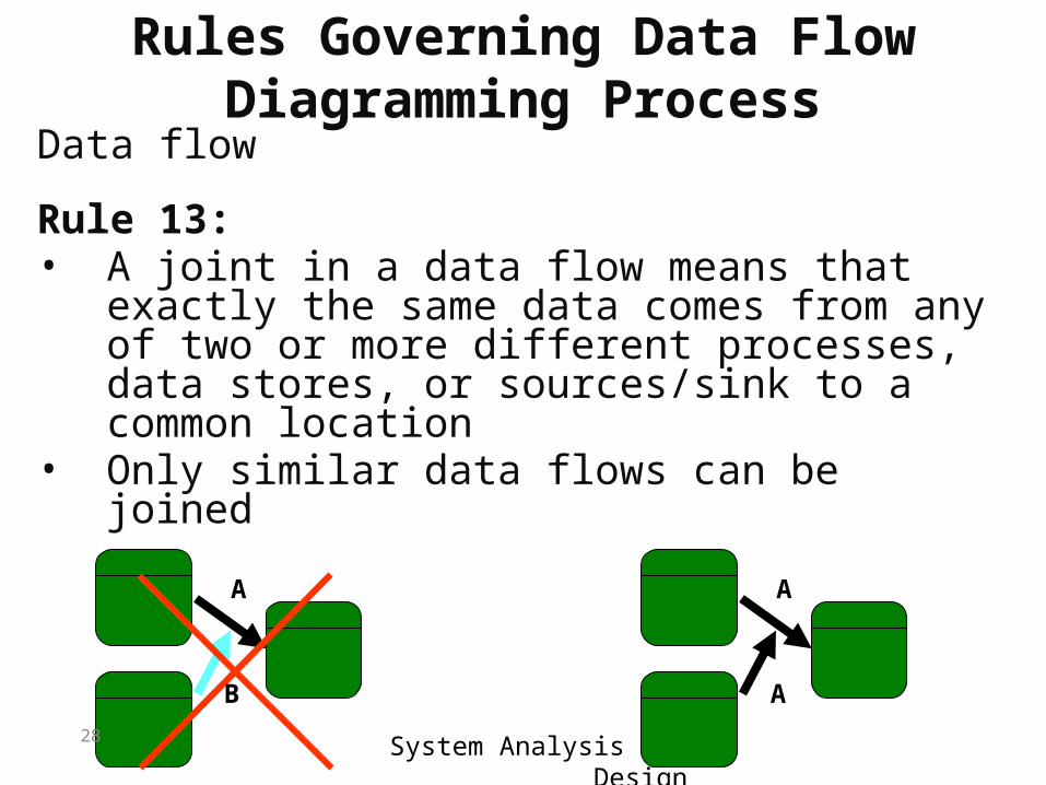
Rule 13:• A joint in a data flow means that exactly the
same data comes from any of two or more different processes, data stores, or sources/sink to a common location
• Only similar data flows can be joined
A
B
A
A
29 System Analysis and Design
Rules Governing Data Flow Diagramming Process
Data flow
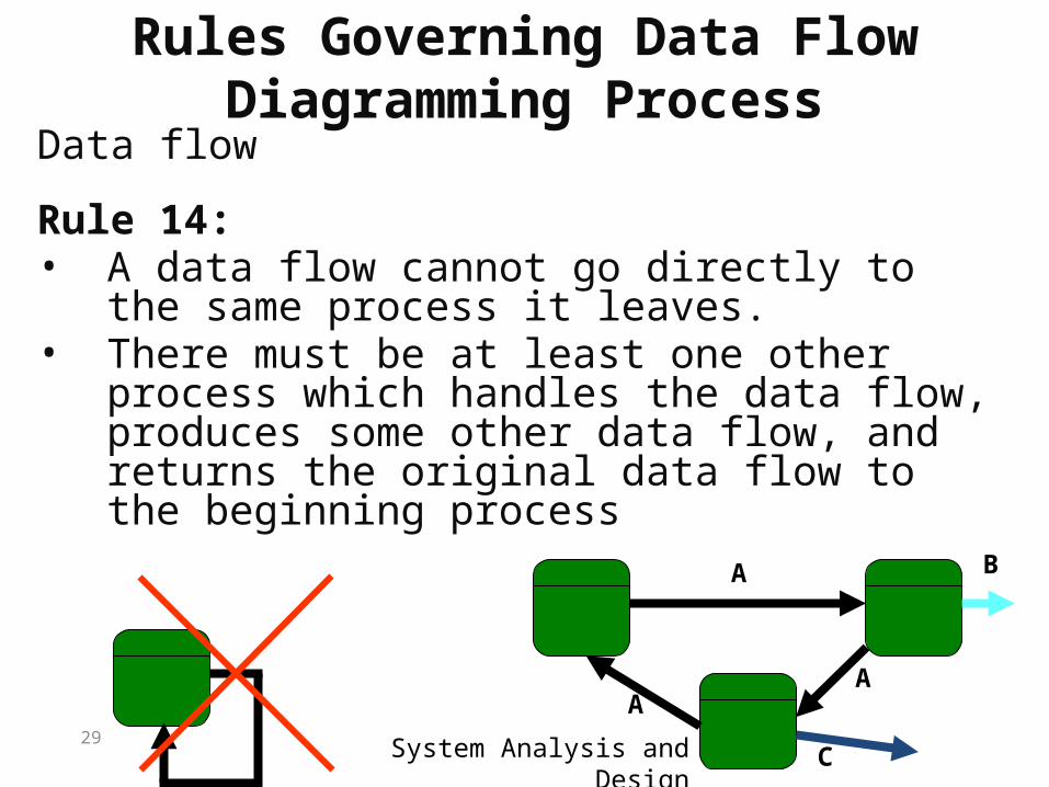
Rule 14:• A data flow cannot go directly to the same
process it leaves.• There must be at least one other process
which handles the data flow, produces some other data flow, and returns the original data flow to the beginning process
A
AA
B
C
30 System Analysis and Design
Rules Governing Data Flow Diagramming Process
Data flow
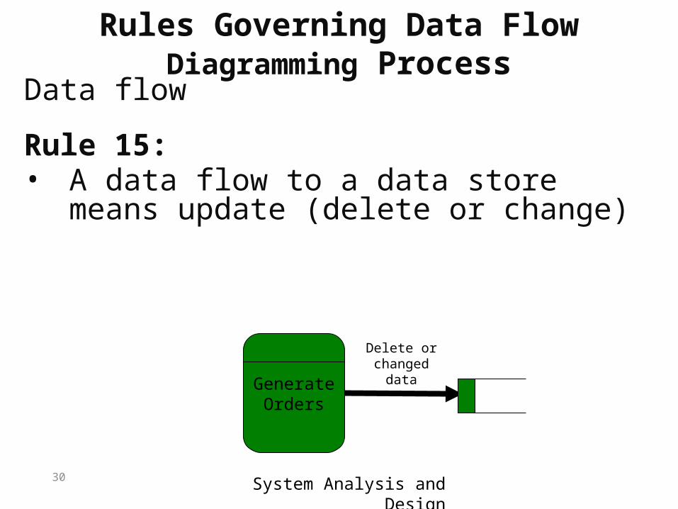
Rule 15:• A data flow to a data store means
update (delete or change)
GenerateOrders
Delete or changed
data
31 System Analysis and Design
Rules Governing Data Flow Diagramming Process
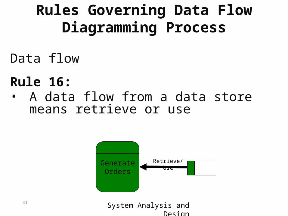
Data flow
Rule 16:• A data flow from a data store means
retrieve or use
GenerateOrders
Retrieve/Use
32 System Analysis and Design
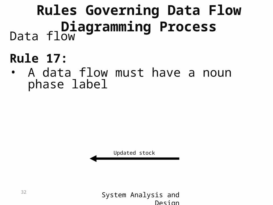
Data flow
Rule 17:• A data flow must have a noun phase
label
Updated stock
Rules Governing Data Flow Diagramming Process
33System Analysis and Design
DFDs Exercises
System Analysis and Design34
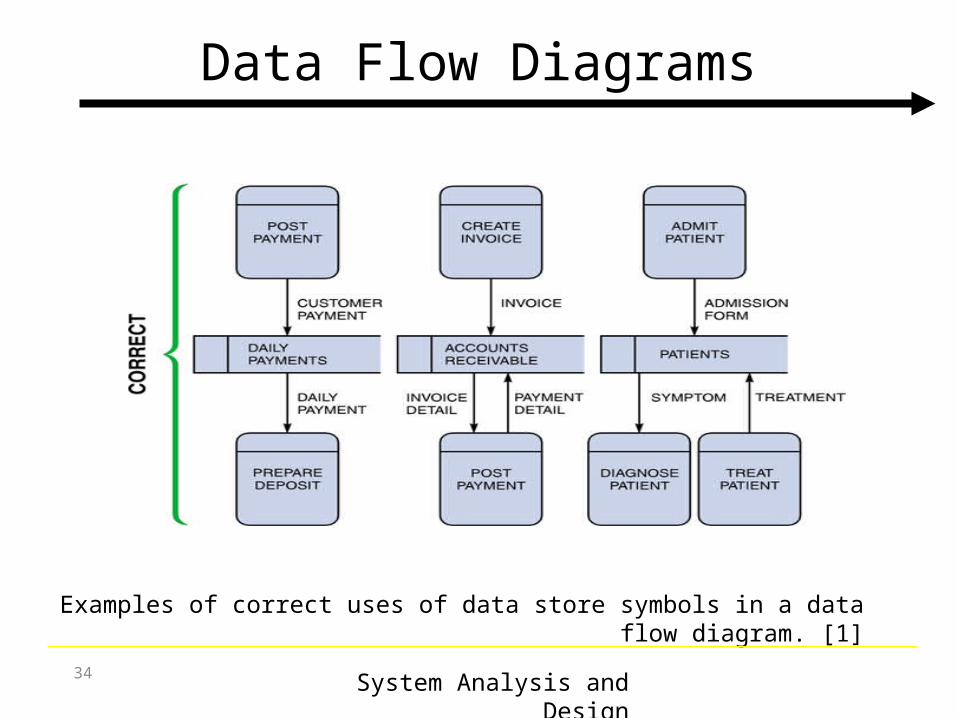
Data Flow Diagrams
Examples of correct uses of data store symbols in a data flow diagram. [1]
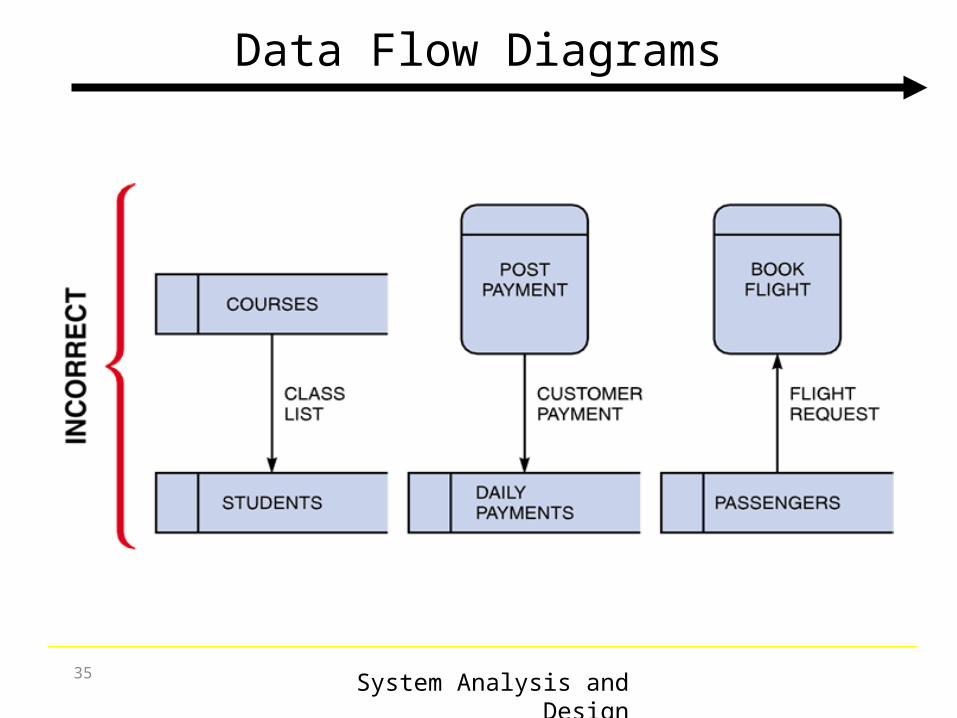
System Analysis and Design35
Data Flow Diagrams
System Analysis and Design36
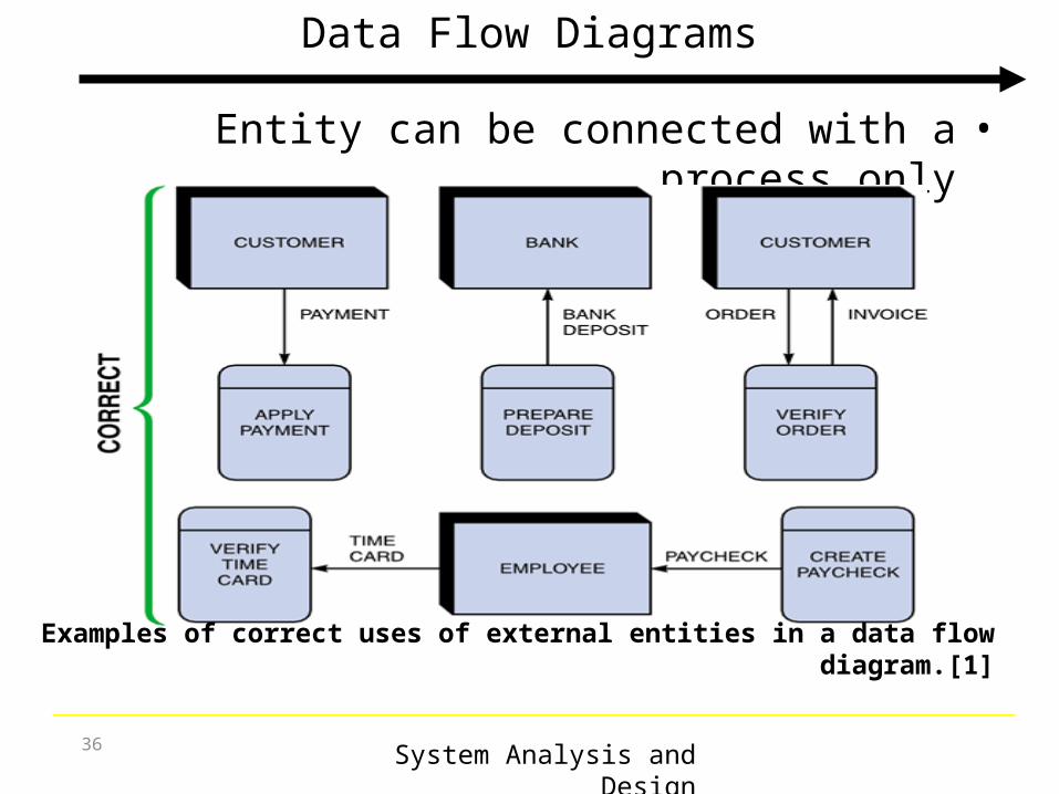
Data Flow Diagrams
•Entity can be connected with a process only
Examples of correct uses of external entities in a data flow diagram.[1]
System Analysis and Design37
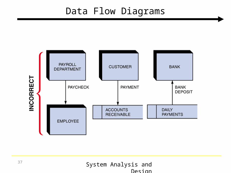
Data Flow Diagrams
System Analysis and Design38
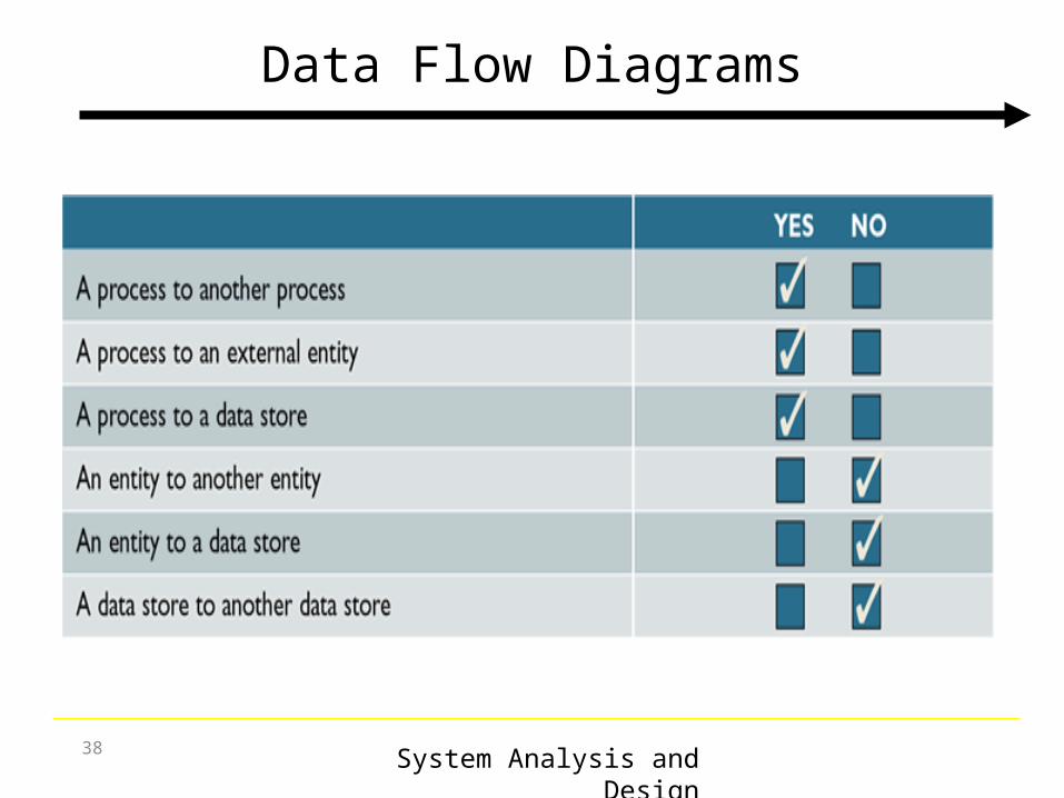
Data Flow Diagrams
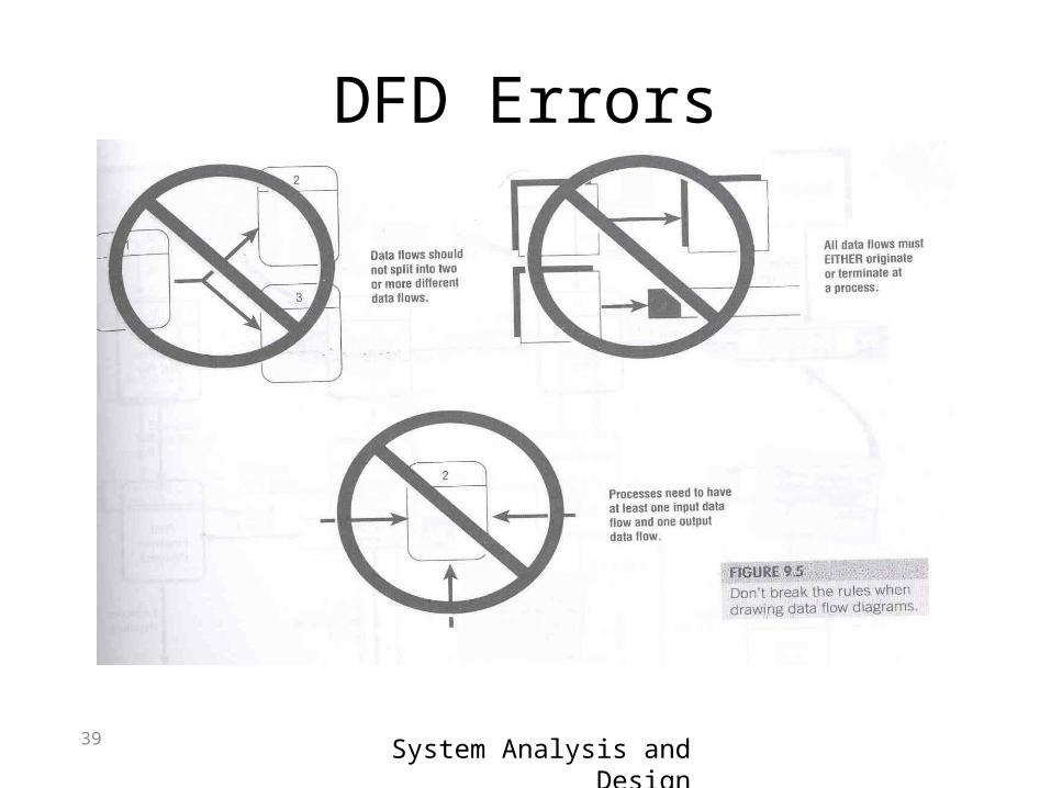
39 System Analysis and Design
DFD Errors
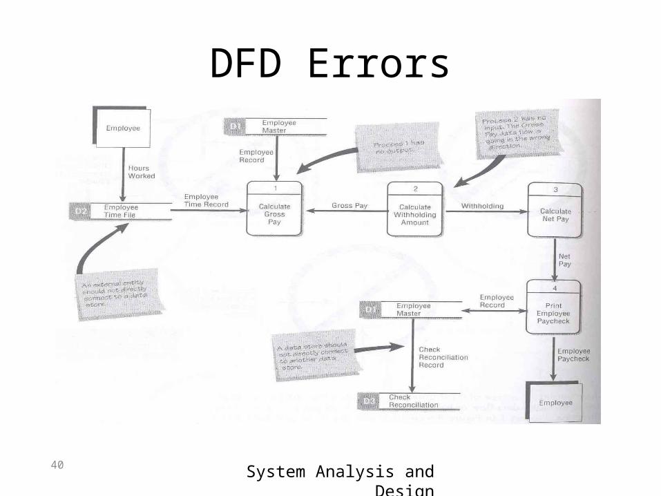
40 System Analysis and Design
DFD Errors