Embed Size (px)
Citation preview
Slide 2 - 1 ADS 2009 (version 1.0) Copyright Agilent Technologies 2009
System Design Fundamentals
Slide 2 - 2 ADS 2009 (version 1.0) Copyright Agilent Technologies 2009
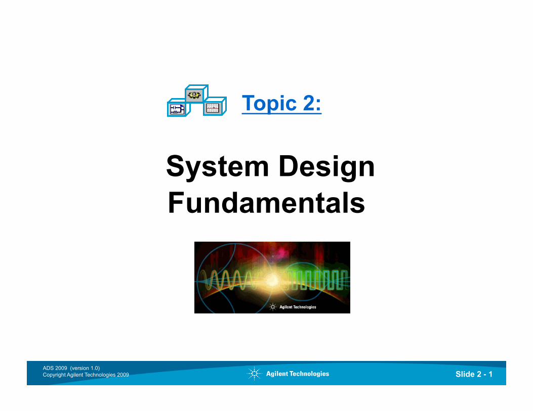
Main Window: File or Project View
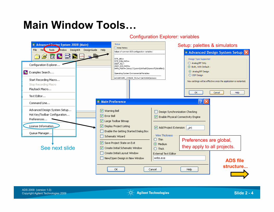
More on Main...
VS
Right Click
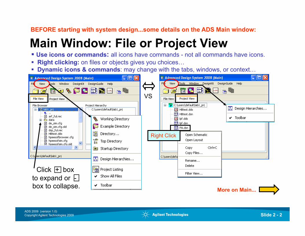
BEFORE starting with system design...some details on the ADS Main window:
Slide 2 - 3 ADS 2009 (version 1.0) Copyright Agilent Technologies 2009
Main Window and the File commands… Design Kits (foundry specific)
Design Guide (like templates)
Next, Tools…
BEFORE starting with system design...some details on the ADS Main window:
Main window is for managing files and projects
Slide 2 - 4 ADS 2009 (version 1.0) Copyright Agilent Technologies 2009
ADS file structure...
Main Window Tools…
See next slide
Slide 2 - 5 ADS 2009 (version 1.0) Copyright Agilent Technologies 2009
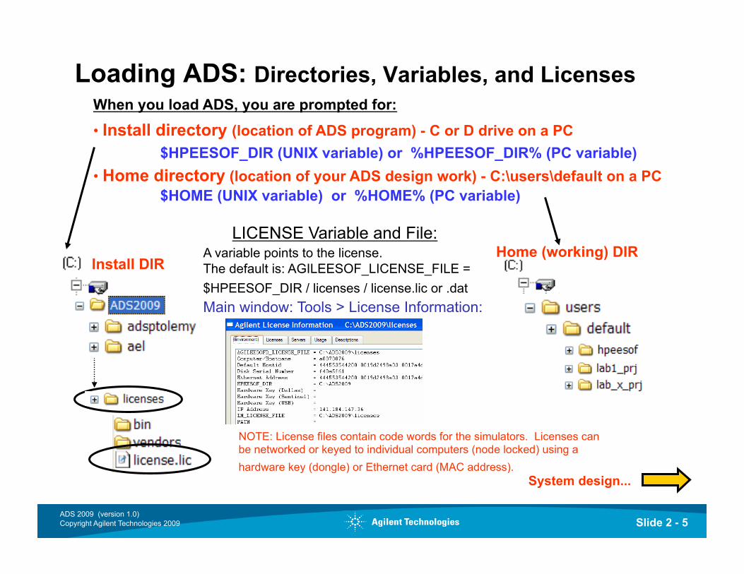
Loading ADS: Directories, Variables, and Licenses
A variable points to the license. The default is: AGILEESOF_LICENSE_FILE = $HPEESOF_DIR / licenses / license.lic or .dat
Install DIR Home (working) DIR
NOTE: License files contain code words for the simulators. Licenses can be networked or keyed to individual computers (node locked) using a hardware key (dongle) or Ethernet card (MAC address).
LICENSE Variable and File:
System design...
Main window: Tools > License Information:
Slide 2 - 6 ADS 2009 (version 1.0) Copyright Agilent Technologies 2009
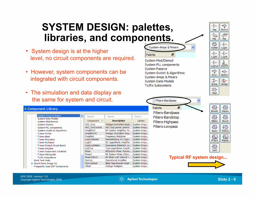
SYSTEM DESIGN: palettes, libraries, and components.
• System design is at the higher level, no circuit components are required.
• However, system components can be integrated with circuit components.
• The simulation and data display are the same for system and circuit.
Typical RF system design...
Slide 2 - 7 ADS 2009 (version 1.0) Copyright Agilent Technologies 2009
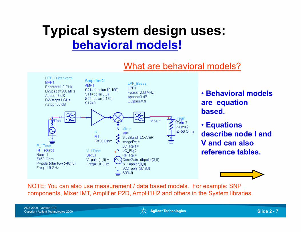
Typical system design uses: behavioral models!
• Behavioral models are equation based.
• Equations describe node I and V and can also reference tables.
What are behavioral models?
NOTE: You can also use measurement / data based models. For example: SNP components, Mixer IMT, Amplifier P2D, AmpH1H2 and others in the System libraries.
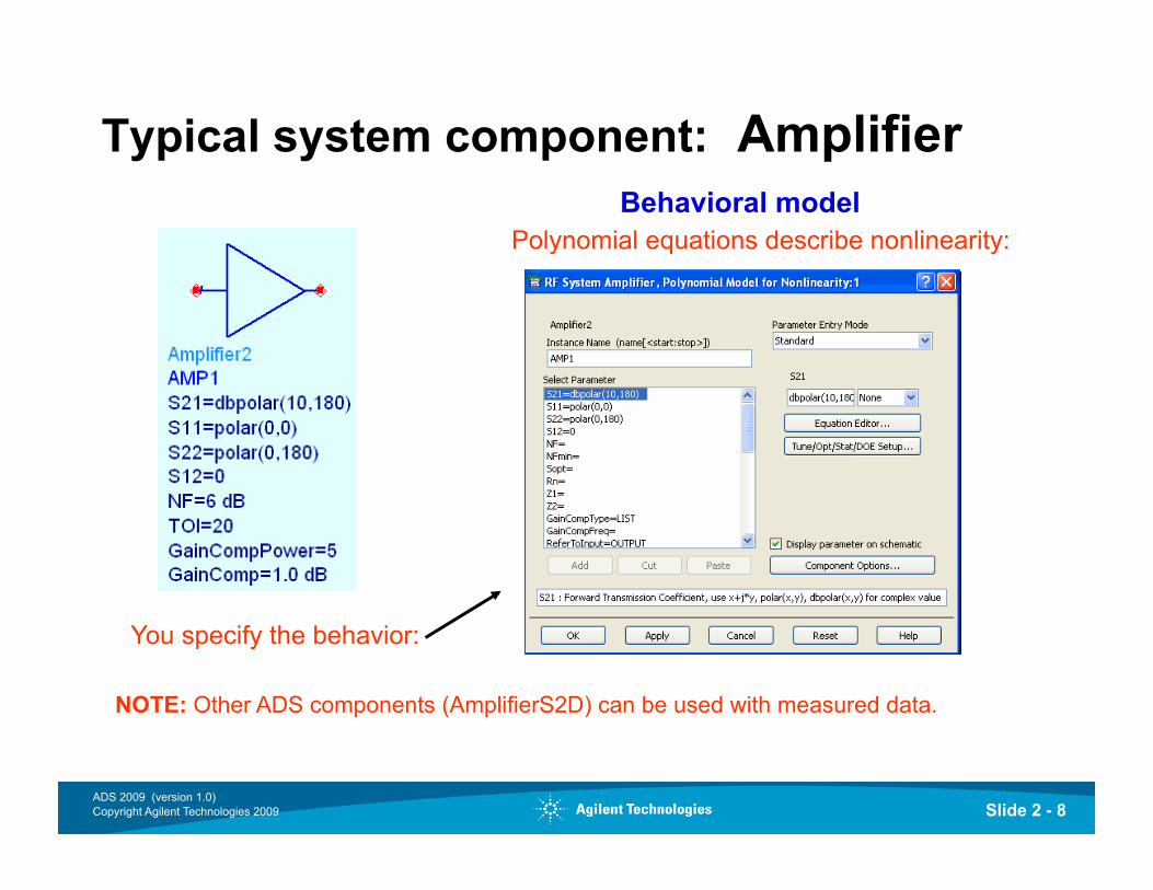
Slide 2 - 8 ADS 2009 (version 1.0) Copyright Agilent Technologies 2009
Typical system component: Amplifier
You specify the behavior:
Polynomial equations describe nonlinearity: Behavioral model
NOTE: Other ADS components (AmplifierS2D) can be used with measured data.
Slide 2 - 9 ADS 2009 (version 1.0) Copyright Agilent Technologies 2009
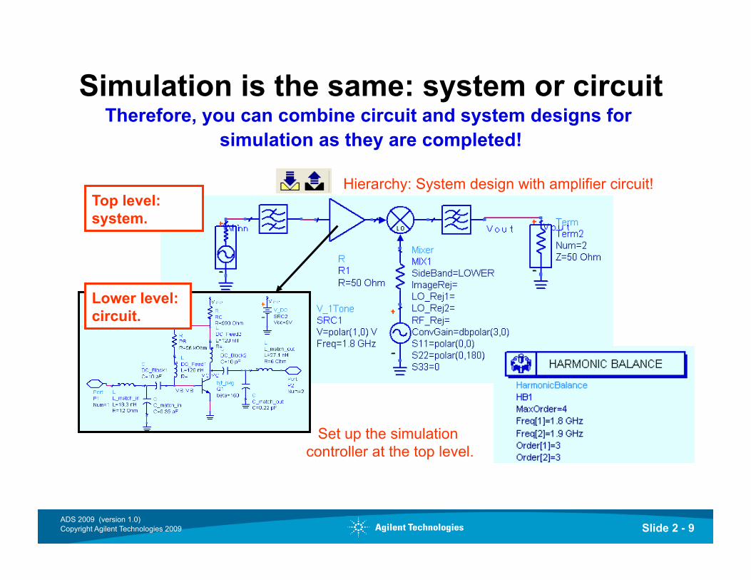
Simulation is the same: system or circuit Therefore, you can combine circuit and system designs for
simulation as they are completed!
Top level: system.
Lower level: circuit.
Hierarchy: System design with amplifier circuit!
Set up the simulation controller at the top level.
Slide 2 - 10 ADS 2009 (version 1.0) Copyright Agilent Technologies 2009
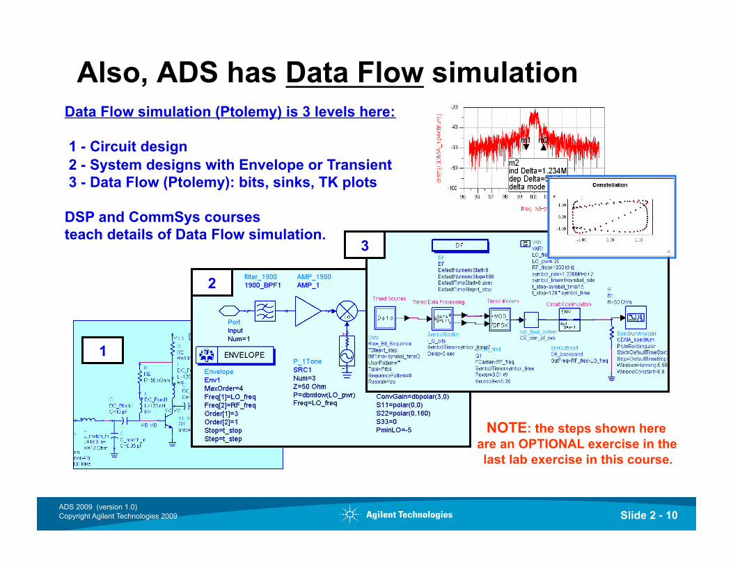
Also, ADS has Data Flow simulation Data Flow simulation (Ptolemy) is 3 levels here:
1 - Circuit design 2 - System designs with Envelope or Transient 3 - Data Flow (Ptolemy): bits, sinks, TK plots
DSP and CommSys courses teach details of Data Flow simulation.
NOTE: the steps shown here are an OPTIONAL exercise in the last lab exercise in this course.
1
3
2
Slide 2 - 11 ADS 2009 (version 1.0) Copyright Agilent Technologies 2009
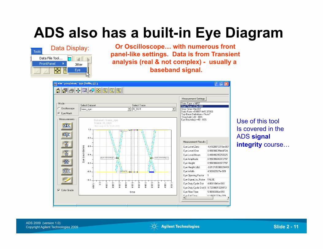
ADS also has a built-in Eye Diagram Or Oscilloscope… with numerous front
panel-like settings. Data is from Transient analysis (real & not complex) - usually a
baseband signal.
Use of this tool Is covered in the ADS signal integrity course…
Data Display:
Slide 2 - 12 ADS 2009 (version 1.0) Copyright Agilent Technologies 2009
Lab 2:
System Design Fundamentals
Slide 2 - 13 ADS 2009 (version 1.0) Copyright Agilent Technologies 2009
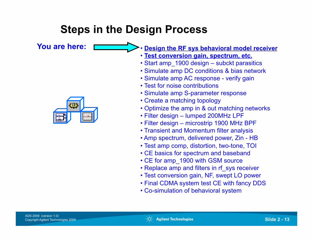
Steps in the Design Process • Design the RF sys behavioral model receiver • Test conversion gain, spectrum, etc. • Start amp_1900 design – subckt parasitics • Simulate amp DC conditions & bias network • Simulate amp AC response - verify gain • Test for noise contributions • Simulate amp S-parameter response • Create a matching topology • Optimize the amp in & out matching networks • Filter design – lumped 200MHz LPF • Filter design – microstrip 1900 MHz BPF • Transient and Momentum filter analysis • Amp spectrum, delivered power, Zin - HB • Test amp comp, distortion, two-tone, TOI • CE basics for spectrum and baseband • CE for amp_1900 with GSM source • Replace amp and filters in rf_sys receiver • Test conversion gain, NF, swept LO power • Final CDMA system test CE with fancy DDS • Co-simulation of behavioral system
You are here:
Slide 2 - 14 ADS 2009 (version 1.0) Copyright Agilent Technologies 2009
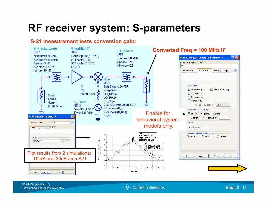
RF receiver system: S-parameters
Converted Freq = 100 MHz IF S-21 measurement tests conversion gain:
Enable for behavioral system
models only.
Plot results from 2 simulations: 10 dB and 20dB amp S21
Slide 2 - 15 ADS 2009 (version 1.0) Copyright Agilent Technologies 2009
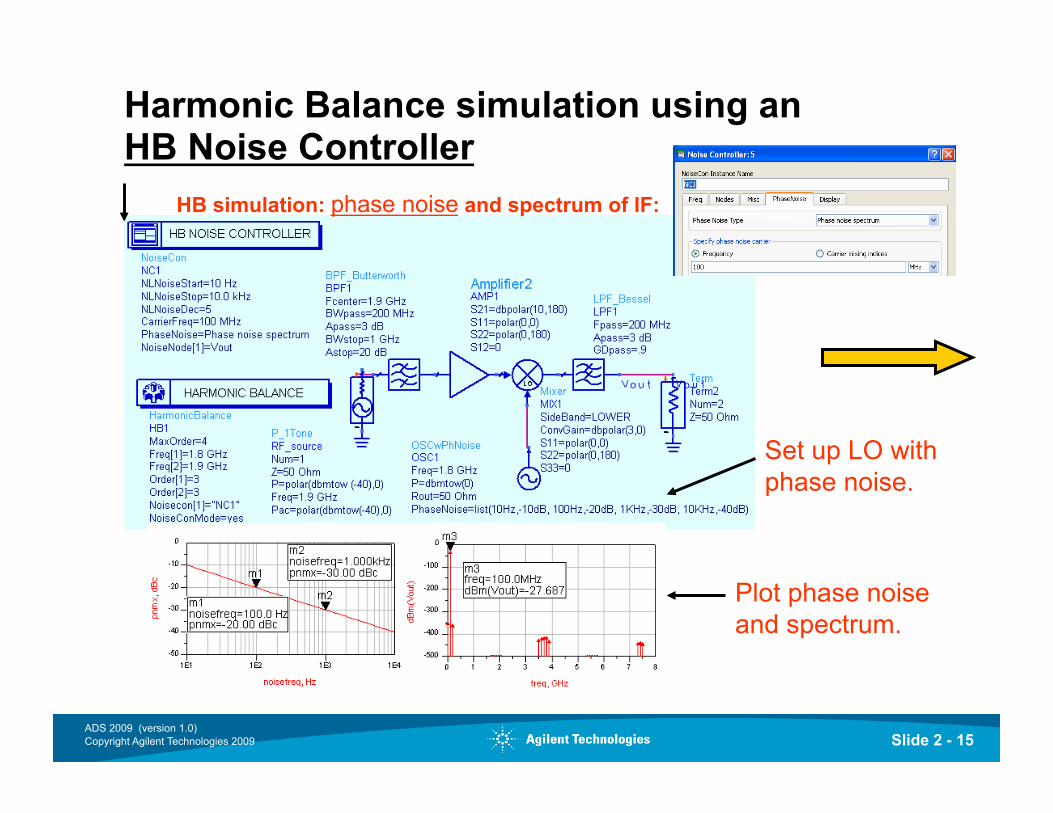
Harmonic Balance simulation using an HB Noise Controller
Set up LO with phase noise.
Plot phase noise and spectrum.
HB simulation: phase noise and spectrum of IF:
Slide 2 - 16 ADS 2009 (version 1.0) Copyright Agilent Technologies 2009
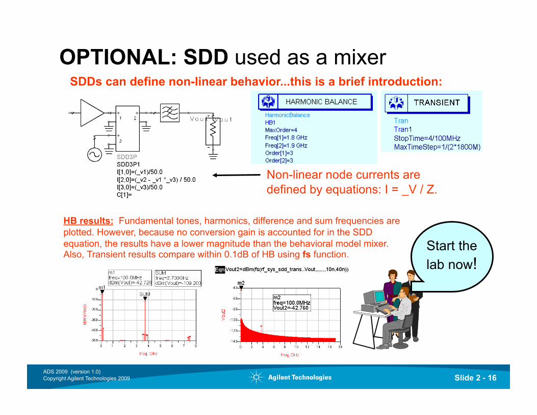
OPTIONAL: SDD used as a mixer
Start the lab now!
Non-linear node currents are defined by equations: I = _V / Z.
SDDs can define non-linear behavior...this is a brief introduction:
HB results: Fundamental tones, harmonics, difference and sum frequencies are plotted. However, because no conversion gain is accounted for in the SDD equation, the results have a lower magnitude than the behavioral model mixer. Also, Transient results compare within 0.1dB of HB using fs function.


![jQuery Fundamentals · jQuery Fundamentals Rebecca Murphey [] jQuery Fundamentals Rebecca Murphey [] Copyright © 2010](https://img.pdfslide.net/doc/110x75/5eb897bf41e49d450f44be28/jquery-fundamentals-jquery-fundamentals-rebecca-murphey-jquery-fundamentals.jpg)