Embed Size (px)
Citation preview
System Grounding in Industrial Plants F. M. D O R E Y
M E M B E R A I E E
THE QUESTION OF electric system grounding in industrial plants
is one that should be considered not only on new plant installations and on modernization of existing plant facilities, but also should be considered with respect to operating existing plant electric systems that were designed originally for ungrounded operation.
NATURE AND CAUSE OF OVERVOLTAGES
THE SOURCES of overvoltages are many and of varied character. The most prominent ones include:
1. Lightning. 2. Static. 3. Physical contact with a higher voltage system. 4. Switching surges. 5. Resonance effects in series inductive-capacitive
circuits. 6. Repetitive restrike (intermittent grounds).
Much has been written concerning overvoltage due to reasons 1, 2, 3, and 4 and the beneficial results obtainable when the system is operated as a grounded system. The scope of this article will be limited to reasons 5 and 6.
RESONANT EFFECTS IN SERIES INDUCTIVE-CAPACITIVE CIRCUITS
UNGROUNDED NEUTRAL a-c systems are most commonly subject to overvoltages originating from this cause.
It is important to recognize that ungrounded neutral systems are actually capacitively coupled to ground rather than truly divorced from ground. Such systems are ungrounded in the sense that no interconnection with ground has been made purposely, but every element of the electric system incorporates some capacitance to ground which constitutes an inherent capacitive impedance interconnection between the electric system conductors and ground.
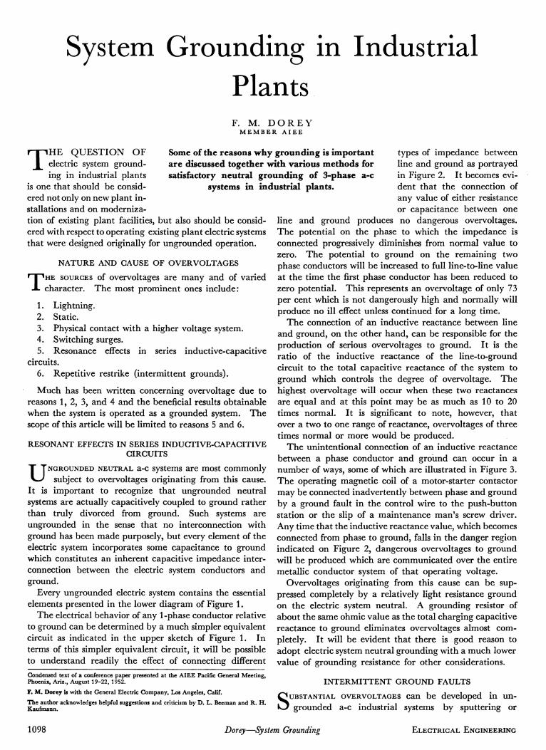
Every ungrounded electric system contains the essential elements presented in the lower diagram of Figure 1.
The electrical behavior of any 1-phase conductor relative to ground can be determined by a much simpler equivalent circuit as indicated in the upper sketch of Figure 1. In terms of this simpler equivalent circuit, it will be possible to understand readily the effect of connecting different Condensed text of a conference paper presented at the ΑΙΕΕ Pacific General Meeting, Phoenix, Ariz., August 19-22, 1952. F. M. Dorey is with the General Electric Company, Los Angeles, Calif. The author acknowledges helpful suggestions and criticism by D. L. Beeman and R. H. Kaufmann.
types of impedance between line and ground as portrayed in Figure 2. It becomes evident that the connection of any value of either resistance or capacitance between one
line and ground produces no dangerous overvoltages. The potential on the phase to which the impedance is connected progressively diminishes from normal value to zero. The potential to ground on the remaining two phase conductors will be increased to full line-to-line value at the time the first phase conductor has been reduced to zero potential. This represents an overvoltage of only 73 per cent which is not dangerously high and normally will produce no ill effect unless continued for a long time.
The connection of an inductive reactance between line and ground, on the other hand, can be responsible for the production of serious overvoltages to ground. It is the ratio of the inductive reactance of the line-to-ground circuit to the total capacitive reactance of the system to ground which controls the degree of overvoltage. The highest overvoltage will occur when these two reactances are equal and at this point may be as much as 10 to 20 times normal. It is significant to note, however, that over a two to one range of reactance, overvoltages of three times normal or more would be produced.
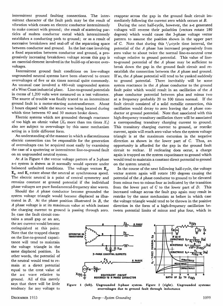
The unintentional connection of an inductive reactance between a phase conductor and ground can occur in a number of ways, some of which are illustrated in Figure 3. The operating magnetic coil of a motor-starter contactor may be connected inadvertently between phase and ground by a ground fault in the control wire to the push-button station or the slip of a maintenance man's screw driver. Any time that the inductive reactance value, which becomes connected from phase to ground, falls in the danger region indicated on Figure 2, dangerous overvoltages to ground will be produced which are communicated over the entire metallic conductor system of that operating voltage.
Overvoltages originating from this cause can be suppressed completely by a relatively light resistance ground on the electric system neutral. A grounding resistor of about the same ohmic value as the total charging capacitive reactance to ground eliminates overvoltages almost completely. It will be evident that there is good reason to adopt electric system neutral grounding with a much lower value of grounding resistance for other considerations.
INTERMITTENT GROUND FAULTS
SUBSTANTIAL OVERVOLTAGES can be developed in ungrounded a-c industrial systems by sputtering or
Some of the reasons why grounding is important are discussed together with various methods for satisfactory neutral grounding of 3-phase a-c
systems in industrial plants.
1098 Dorey—System Grounding ELECTRICAL ENGINEERING
intermittent ground faulting connections. The intermittent character of the fault path may be the result of vibration which causes an electric conductor intermittently to make contact with ground; the result of scattering particles of molten conductor metal which intermittently establishes a conducting path to ground; or as a result of successive breakdown and seal-off of the separating space between conductor and ground. In the last case involving a fixed separation between conductor and ground, a progressively increasing breakdown voltage across this gap is an essential element involved in the build-up of severe over-voltages.
Intermittent ground fault conditions on low-voltage ungrounded neutral systems have been observed to create overvoltages of five or six times normal quite commonly. An unusual case involved a 480-volt ungrounded system of a West Coast industrial plant. Line-to-ground potentials in excess of 1,200 volts were measured on a test voltmeter. The source of trouble was finally traced to an intermittent ground fault in a motor-starting autotransformer. About 2 hours elapsed while the source was being located during which time between 40 and 50 motors broke down.
Electric systems which are grounded through reactance of too high an ohmic value (X0 more than ten times Xi) also are subject to overvoltage by this same mechanism acting in a little different form.
An understanding of the manner in which a discontinuous electric connection can be responsible for the generation of overvoltages can be acquired most easily by examining the case of a sputtering or intermittent line-to-ground fault on an ungrounded neutral system.
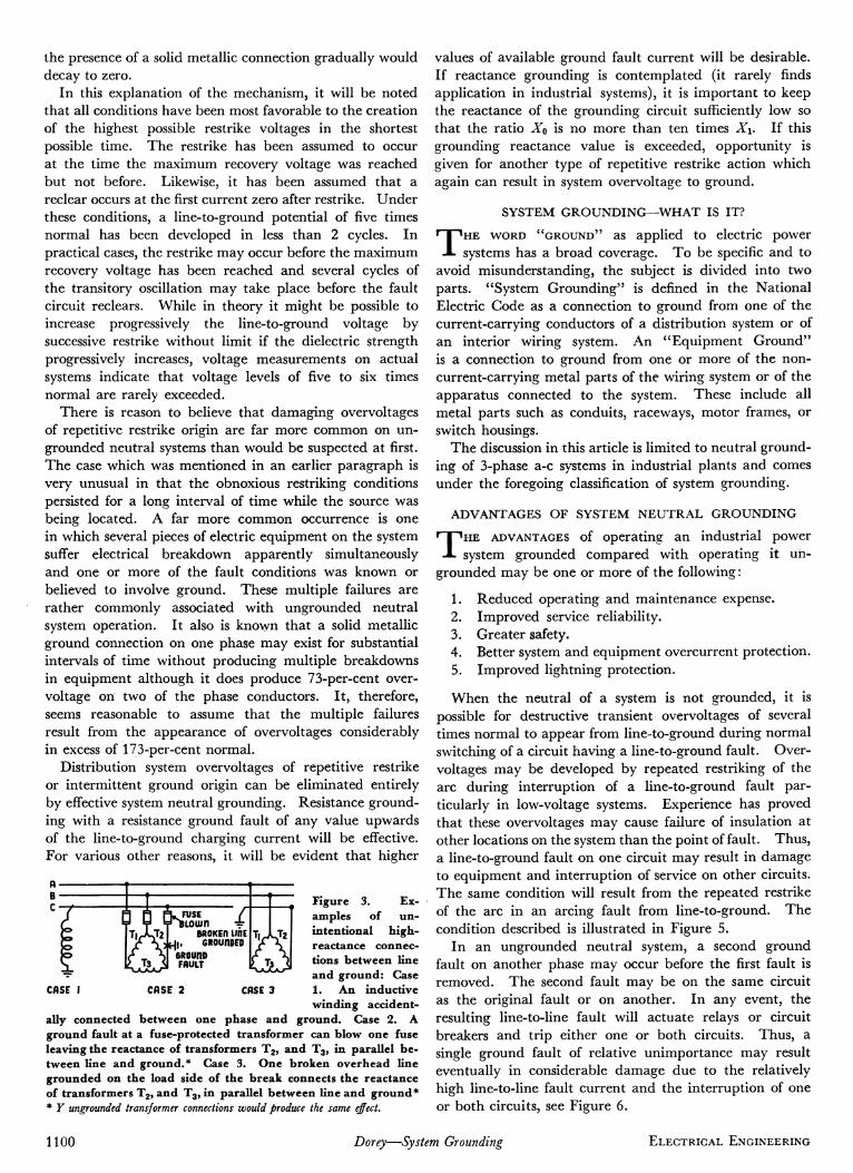
At A in Figure 4 the vector voltage pattern of a 3-phase a-c system is shown as it normally would operate under balanced unfaulted conditions. The voltage vectors Ea, Eô, and Ec rotate about the neutral at synchronous speed. The electric neutral is a point of central symmetry and remains constant at ground potential if the individual phase voltages are pure fundamental-frequency sine waves.
Should the A phase conductor become grounded the system voltage triangle would become displaced as illustrated in B. At the phase position illustrated in B, the A phase voltage is at its maximum value at which instant the charging current to ground is passing through zero. In case the fault circuit contains a small gap or an arc, the arc current would become a extinguished at this point. Note that the trapped charge on the line-to-ground capacitance will tend to maintain the voltage triangle in the same displaced position. In other words, the potential of the neutral would tend to remain at a direct potential equal to the crest value of the a-c wave relative to ground. All of this merely says that there will be little tendency for any voltage to
GEflERATOR OR TRRflSFORfflER
reappear across the gap in the ground fault circuit immediately following the current zero which occurs at B.
During the next half-cycle, however, the a-c generated voltages will reverse their polarities (vectors rotate 180 degrees) which would cause the 3-phase voltage vector pattern to assume the position shown in the upper part of C. Note that during this V2-cycle time interval, the potential of the A phase has increased progressively from zero value to about twice the normal line-to-neutral crest voltage relative to ground potential. This value of line-to-ground potential of the A phase may be sufficient to break down the gap in the ground fault circuit and reestablish the connection between the A phase and ground. If so, the A phase potential will tend to be yanked suddenly to ground potential. There inevitably will be some system reactance in the A phase conductor to the ground fault point which would result in an oscillation of the A phase conductor potential between plus and minus two at a frequency probably 20 to 100 times normal. If the fault circuit consisted of a solid metallic connection, this oscillation would decay to zero leaving the A phase conductor at ground potential. Note that associated with this high-frequency transitory oscillation there will be associated a corresponding transitory charging current to ground. This transitory charging current to ground, or restrike current, again will reach zero value when the system voltage triangle is at the maximum excursion in the negative direction as shown in the lower part of C. Thus, an opportunity is afforded for the gap in the ground fault circuit to reclear. If reclearing does occur, a charge again is trapped on the system capacitance to ground which would tend to maintain a constant direct potential to ground on the system neutral.
In the course of the next following half-cycle, the voltage vector system again will rotate 180 degrees causing the potential of the A phase conductor to ground to be elevated from minus two to minus four as indicated by the transition from the lower part of C to the lower part of D. This increased voltage across the fault gap again may result in restrike by the same mechanism as before in which case the voltage triangle would tend to be thrown in the positive direction in the form of a high-frequency oscillation between potential limits of minus and plus four, which in
Xs P PHASE
Xs - Λ Κ Ρ —
T Ça
x9?/s
* ! ·
I l l T y T
Xco - 'TRP—
3-PHASE ESSENTIAL ELEfflEnTS
Xs VWV n PHASE
Χ % : * a YT"
EQUIVflLEnT CIRCUIT REFERRED TO A PHASE COflDUCTOR
\/S^TXC0/5)2
(Ea)
RATIO OF ZF TO X C O / 3
Figure 1 (left). Ungrounded 3-phase system. Figure 2 (right). Ungrounded systems: overvoltages due to ground fault through inductance
DECEMBER 1953 Dorey—System Grounding 1099
the presence of a solid metallic connection gradually would decay to zero.
In this explanation of the mechanism, it will be noted that all conditions have been most favorable to the creation of the highest possible restrike voltages in the shortest possible time. The restrike has been assumed to occur at the time the maximum recovery voltage was reached but not before. Likewise, it has been assumed that a reclear occurs at the first current zero after restrike. Under these conditions, a line-to-ground potential of five times normal has been developed in less than 2 cycles. In practical cases, the restrike may occur before the maximum recovery voltage has been reached and several cycles of the transitory oscillation may take place before the fault circuit reclears. While in theory it might be possible to increase progressively the line-to-ground voltage by successive restrike without limit if the dielectric strength progressively increases, voltage measurements on actual systems indicate that voltage levels of five to six times normal are rarely exceeded.
There is reason to believe that damaging overvoltages of repetitive restrike origin are far more common on ungrounded neutral systems than would be suspected at first. The case which was mentioned in an earlier paragraph is very unusual in that the obnoxious restriking conditions persisted for a long interval of time while the source was being located. A far more common occurrence is one in which several pieces of electric equipment on the system suffer electrical breakdown apparently simultaneously and one or more of the fault conditions was known or believed to involve ground. These multiple failures are rather commonly associated with ungrounded neutral system operation. It also is known that a solid metallic ground connection on one phase may exist for substantial intervals of time without producing multiple breakdowns in equipment although it does produce 73-per-cent over-voltage on two of the phase conductors. It, therefore, seems reasonable to assume that the multiple failures result from the appearance of overvoltages considerably in excess of 173-per-cent normal.
Distribution system overvoltages of repetitive restrike or intermittent ground origin can be eliminated entirely by effective system neutral grounding. Resistance grounding with a resistance ground fault of any value upwards of the line-to-ground charging current will be effective. For various other reasons, it will be evident that higher
Y FUSE Loujn
BROKEn ΙΙΠΕ )kj | . GROUnDED
6R0UnD FAULT ö
Ex-
CASE I CASE 2 CASE 3
Figure 3. amples of unintentional high-reactance connections between line and ground: Case 1. An inductive winding accident
ally connected between one phase and ground. Case 2. A ground fault at a fuse-protected transformer can blow one fuse leaving the reactance of transformers T2, and T3, in parallel between line and ground.* Case 3. One broken overhead line grounded on the load side of the break connects the reactance of transformers T2, and T3, in parallel between line and ground* * Y ungrounded transformer connections would produce the same effect.
values of available ground fault current will be desirable. If reactance grounding is contemplated (it rarely finds application in industrial systems), it is important to keep the reactance of the grounding circuit sufficiently low so that the ratio XQ is no more than ten times X\. If this grounding reactance value is exceeded, opportunity is given for another type of repetitive restrike action which again can result in system overvoltage to ground.
SYSTEM GROUNDING—WHAT IS IT?
THE WORD ''GROUND" as applied to electric power systems has a broad coverage. To be specific and to
avoid misunderstanding, the subject is divided into two parts. "System Grounding" is defined in the National Electric Gode as a connection to ground from one of the current-carrying conductors of a distribution system or of an interior wiring system. An "Equipment Ground" is a connection to ground from one or more of the non-current-carrying metal parts of the wiring system or of the apparatus connected to the system. These include all metal parts such as conduits, raceways, motor frames, or switch housings.
The discussion in this article is limited to neutral grounding of 3-phase a-c systems in industrial plants and comes under the foregoing classification of system grounding.
ADVANTAGES OF SYSTEM NEUTRAL GROUNDING
THE ADVANTAGES of operating an industrial power system grounded compared with operating it un
grounded may be one or more of the following :
1. Reduced operating and maintenance expense. 2. Improved service reliability. 3. Greater safety. 4. Better system and equipment overcurrent protection. 5. Improved lightning protection.
When the neutral of a system is not grounded, it is possible for destructive transient overvoltages of several times normal to appear from line-to-ground during normal switching of a circuit having a line-to-ground fault. Overvoltages may be developed by repeated restriking of the arc during interruption of a line-to-ground fault particularly in low-voltage systems. Experience has proved that these overvoltages may cause failure of insulation at other locations on the system than the point of fault. Thus, a line-to-ground fault on one circuit may result in damage to equipment and interruption of service on other circuits. The same condition will result from the repeated restrike of the arc in an arcing fault from line-to-ground. The condition described is illustrated in Figure 5.
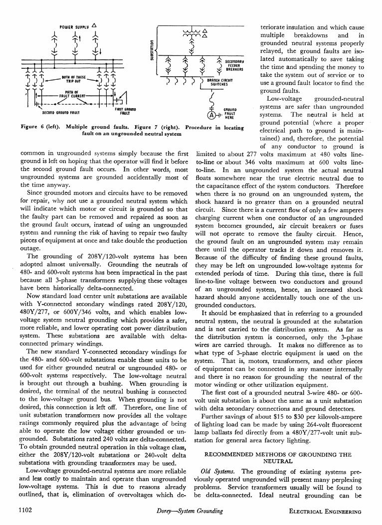
In an ungrounded neutral system, a second ground fault on another phase may occur before the first fault is removed. The second fault may be on the same circuit as the original fault or on another. In any event, the resulting line-to-line fault will actuate relays or circuit breakers and trip either one or both circuits. Thus, a single ground fault of relative unimportance may result eventually in considerable damage due to the relatively high line-to-line fault current and the interruption of one or both circuits, see Figure 6.
1100 Dorey—System Grounding ELECTRICAL ENGINEERING

h-JcYClE _ | « - £ CYCLE-*t fa
Ea NORIML
When the system neutral is properly grounded, these transient overvoltages are greatly reduced and experience shows that multiple ground faults are rare. Thus, from this consideration grounded neutral systems have lower operating cost and better service reliability.
When the neutral of a system is not grounded, a ground fault on one phase causes full line-to-line voltage to appear throughout the system between ground and the two un-faulted phases. This voltage is 73 per cent higher than normal.
Usually the insulation between each line and ground is adequate to withstand full line-to-line voltage. However, if this voltage is applied for long periods, it may result in failure of insulation which may have deteriorated due to age or severe service condition.
While multiple failures from this cause are less frequent than from transient overvoltages, nevertheless when one does occur, it means more maintenance and operating expense and lower service reliability. Properly grounded systems overcome these disadvantages.
Line-to-ground faults on ungrounded neutral systems cause a very small ground fault current to flow through the capacitance of cables, transformers, and other electric equipment on the system. This current may have a magnitude from a few amperes to 25 amperes or more on larger systems. This is not, in general, enough to actuate protective devices, but it may do considerable damage if allowed to flow for a long period of time.
In a system with neutral properly grounded, and with adequate overcurrent relaying, the ground fault current will be higher but it will be removed quickly. This often results in less damage at the point of fault and reduces the cost of repair.
Even though a plant operator may have experienced no displaced neutral, no excessive burning due to charging current, nor multiple faults due to transient overvoltages, it still costs money to find ground faults in an ungrounded neutral system. Ground detectors on an ungrounded neutral system will indicate the existence of a ground fault but will not give its location.
Several devices are available for determining the approximate location of ground faults but they, in general, require skill to operate and may not be too practical in the average industrial plant. The usual procedure in locating a ground fault is to open each circuit individually until the faulted current is located. Should there be two faults on the same phase of different feeders, all feeders must be opened and then closed one at a time to find the faulted feeder. This is costly and reduces service reliability because service is dropped while looking for the fault. Take the case of Figure 7 with a ground fault at A. While one can see from the diagram where the fault
unGROunKD POWER SOURCE
Ea Ml Uli FAULTED
CIRCUIT
i TRPnsiEnT OVERVOLTAGES may CRUSE SECORO FRUIT HERE.
m Slfl6lE LinE-TO-GROUnO FAULT
BREAKER MTERRUPTMG FAULT
Figure 4 (left). Overvoltages developed by repetitive restrike on ungrounded systems. Figure 5 (above). Transient overvoltages during interruption of line-to-ground fault on ungrounded
system
is, one usually cannot see where the ground fault is in an actual ungrounded plant power system. The first step is to open the secondary feeders one at a time. This will tell which feeder the fault is on. This means dropping at least one feeder if you are lucky and hit the grounded feeder first or all feeders if the ground is on the last feeder opened. After finding which feeder the fault is on, then the branch circuits are opened one at a time and finally the motors and loads taken off one at a time. If this is done during production hours, one readily can see how much production loss there will be just to find a ground fault in an ungrounded system. This is contrasted with a grounded neutral system where only the motor A, Figure 7, would have been tripped out and hence no other production machines interfered with.
Often it is argued, however, that with an ungrounded system one ground fault can be left on the system until it is convenient to locate it without interfering with production. Under modern working conditions this may mean after the regular shift, if the plant has only one shift. In some continuous processes like a paper mill, this means the fault locating can be done only on week ends. In processes that run the year round, such as a glass plant, it means that ground faults can be hunted only during vacations. In single-shift plants, hunting ground faults after regular working hours may mean overtime pay.
Because of the factors just mentioned, the tendency is to let the ground faults in an ungrounded system go until the plant shuts down or it is convenient to locate the fault. This practice, however, results in most cases in even poorer service continuity. While it is true that the grounded motor, Figure 7, was not affected with the first ground fault, the system having this one ground is subject to a double outage should a second ground fault occur on another phase.
When this happens, two circuits are tripped out. Now there are two emergency outages, and double the loss of production that would have occurred in grounded neutral system where the ground faults are isolated automatically. With service crews generally available, it takes more than twice as long to repair two ground faults at once than it does to repair two nonconcurrent faults particularly if the two concurrent faults are in isolated parts of the plants.
Experience has shown that double ground faults are
DECEMBER 1953 Dorey—System Grounding 1101
POU)ER SUPPLÌ*
A ί X "5 X il ΐ ""ili
>L >L ^
. BOTH OF THESE TRIP OUT "
PATH OF - FAULT CURREHT-
T *T T * ) ) )
>L >U >1^
IT 3 _£
3 I Y
SEConoflRy FEEDER
BREAKERS
.) ) .) ) )
Nl . ^ _ _ _ : ^ .
sEcono GROuno FAULT FIRST GROUIID
FAULT
BRRnCH CIRCUIT SWITCHES
GROUnD . FAULT
HERE
Figure 6 (left). Multiple ground faults. Figure 7 (right). fault on an ungrounded neutral system
Procedure in locating
common in ungrounded systems simply because the first ground is left on hoping that the operator will find it before the second ground fault occurs. In other words, most ungrounded systems are grounded accidentally most of the time anyway.
Since grounded motors and circuits have to be removed for repair, why not use a grounded neutral system which will indicate which motor or circuit is grounded so that the faulty part can be removed and repaired as soon as the ground fault occurs, instead of using an ungrounded system and running the risk of having to repair two faulty pieces of equipment at once and take double the production outage.
The grounding of 208Y/l20-volt systems has been adopted almost universally. Grounding the neutrals of 480- and 600-volt systems has been impractical in the past because all 3-phase transformers supplying these voltages have been historically delta-connected.
Now standard load center unit substations are available with Y-connected secondary windings rated 208Y/120, 480Y/277, or 600Y/346 volts, and which enables low-voltage system neutral grounding which provides a safer, more reliable, and lower operating cost power distribution system. These substations are available with delta-connected primary windings.
The new standard Y-connected secondary windings for the 480- and 600-volt substations enable these units to be used for either grounded neutral or ungrounded 480- or 600-volt systems respectively. The low-voltage neutral is brought out through a bushing. When grounding is desired, the terminal of the neutral bushing is connected to the low-voltage ground bus. When grounding is not desired, this connection is left off. Therefore, one line of unit substation transformers now provides all the voltage ratings commonly required plus the advantage of being able to operate the low voltage either grounded or ungrounded. Substations rated 240 volts are delta-connected. To obtain grounded neutral operation in this voltage class, either the 208Y/l20-volt substations or 240-volt delta substations with grounding transformers may be used.
Low-voltage grounded-neutral systems are more reliable and less costly to maintain and operate than ungrounded low-voltage systems. This is due to reasons already outlined, that is, elimination of overvoltages which de
teriorate insulation and which cause multiple breakdowns and in grounded neutral systems properly relayed, the ground faults are isolated automatically to save taking the time and spending the money to take the system out of service or to use a ground fault locator to find the ground faults.
Low-voltage grounded-neutral systems are safer than ungrounded systems. The neutral is held at ground potential (where a proper electrical path to ground is maintained) and, therefore, the potential of any conductor to ground is
limited to about 277 volts maximum at 480 volts line-to-line or about 346 volts maximum at 600 volts line-to-line. In an ungrounded system the actual neutral floats somewhere near the true electric neutral due to the capacitance effect of the system conductors. Therefore when there is no ground on an ungrounded system, the shock hazard is no greater than on a grounded neutral circuit. Since there is a current flow of only a few amperes charging current when one conductor of an ungrounded system becomes grounded, air circuit breakers or fuses will not operate to remove the faulty circuit. Hence, the ground fault on an ungrounded system may remain there until the operator tracks it down and removes it. Because of the difficulty of finding these ground faults, they may be left on ungrounded low-voltage systems for extended periods of time. During this time, there is full line-to-line voltage between two conductors and ground of an ungrounded system, hence, an increased shock hazard should anyone accidentally touch one of the ungrounded conductors.
It should be emphasized that in referring to a grounded neutral system, the neutral is grounded at the substation and is not carried to the distribution system. As far as the distribution system is concerned, only the 3-phase wires are carried through. It makes no difference as to what type of 3-phase electric equipment is used on the system. That is, motors, transformers, and other pieces of equipment can be connected in any manner internally and there is no reason for grounding the neutral of the motor winding or other utilization equipment.
The first cost of a grounded neutral 3-wire 480- or 600-volt unit substation is about the same as a unit substation with delta secondary connections and ground detectors.
Further savings of about $15 to $30 per kilovolt-ampere of lighting load can be made by using 264-volt fluorescent lamp ballasts fed directly from a 480Y/277-volt unit substation for general area factory lighting.
RECOMMENDED METHODS OF GROUNDING THE NEUTRAL
Old Systems. The grounding of existing systems previously operated ungrounded will present many perplexing problems. Service transformers usually will be found to be delta-connected. Ideal neutral grounding can be
1102 Dorey—System Grounding ELECTRICAL ENGINEERING
accomplished using a separate grounding transformer. Mid-phase grounding is a next best solution but limited to cases using banked single-phase transformers. Gorner-of-the-delta grounding also will achieve most of the desired objectives but with a somewhat greater number of undesirable compromises.
Unless the existing system is in good condition, of reasonably modern design, and adequate from a short-circuit standpoint, the best long-range plan for the customer well may be a modernization program using new load-center unit substations.
Grounding Transformer. Application of a grounding transformer is one possible solution. It is desirable that sufficient ground fault current be available to actuate instantaneous trip coils on feeder circuit breakers. This would be 15 times the rating of the largest feeder circuit breaker, thus the size and cost of a suitable grounding transformer will be a sizeable item.
Corner-of-Delta Grounding. The grounding of one phase conductor often is proposed as a solution to the system grounding problem. While this procedure will satisfy most of the system grounding objectives, it contains several rather serious disadvantages, namely:
1. Throughout the system, two phases are forced to operate continuously with a line-to-ground potential 73 per cent greater than necessary; while the third operates with zero electrical stress.
2. The National Electrical Code requires that motor circuits containing only two overload relays be so wired that the overload units are in the ungrounded conductors. Meeting this requirement could be an annoying costly proposition.
3. A ground fault on the grounded phase conductor causes no protector operation yet allows diversion of load current to the building ground system at the point of fault contact with attendant sputtering and local heating.
4. Sustained operation of circuits with 100-per-cent zero sequence voltage (one conductor at ground potential) may be responsible for induction of stray signals into adjacent signal or communication circuits.
In view of these compromises involved in corner-of-delta grounding, it would be well to recommend strongly that the user adopt neutral grounding conceding corner-of-delta grounding as a compromise solution, which well might prove to be more expensive than neutral grounding on an over-all basis.
Mid-Phase Grounding. Grounding of the mid-point of one phase of the delta is applicable to banked single-phase transformers. While this method of grounding is less desirable than neutral grounding, it is better than corner-of-the-delta grounding. All phase conductors are "hot" to ground. One conductor would operate at 150 per cent while the other two would operate at 87 per cent of the ideal potential to ground.
Keep in mind that this grounding method is applicable to banks of single-phase transformers. It offers no advantage in the case of 3-phase transformers. It never would it be considered for a load center substation.
CONCLUSIONS
PROPER SYSTEM GROUNDING pays dividends on low- as well as medium-voltage systems. The number of
industrial plants operated with grounded electric systems has been expanding rapidly. Many critical industrial process plants such as glass, paper, steel, and cement are operating with their low-voltage system grounded. From these critical process plants as well as others, the operating data show improved electric system performance and fewer equipment outages after the grounding of the distribution system.
The problem now is one of education to overcome the inertia of years of ungrounded system experience. Without a doubt, the ungrounded system originated as a happenstance rather than a planned affair. The three terminals of the source were simply connected through to the three terminals of the load machines. The 480-volt Y transformer is now a listed standard load center substation with many manufacturers. This is suitable for universal service, grounded or ungrounded. Plant engineers who now believe that ungrounded operation is better should be strongly urged to adopt the 480-volt Y substation. It will meet their present desired ungrounded service requirements and 2 or 3 years hence, when they become convinced of the merits of the grounded operation, the stations can be converted by merely grounding the low-voltage neutral bushing to ground. The number of unit substations sold by the electrical industry in the last 4 years has shown an astounding rise in the proportion of transformers with a neutral bushing brought out so that the system can be operated as a grounded neutral system if so desired.
This marks a very definite trend by the electrical industry; the grounded neutral system for industrial plant operation will become more and more universal as time passes and every electrical engineer concerned with industrial plant electrical operation should be well aware of the merits.
Reactor Sphere Completed The Atomic Energy Commission has announced that the
large steel sphere at the Knolls Atomic Power Laboratory, West Milton, N. Y., has been completed. The sphere will be used for test operations by the General Electric Company on a prototype atomic power plant for submarines.
Closing of the last openings at top and bottom marked the end of 10 months' work. A total of 682 steel plates were joined together to make the structure which, together with its supporting columns, weighs 3,850 tons. The sphere is 225 feet in diameter and is higher than an 18-story building.
Purpose of the housing is to provide insurance against the escape of radioactive material in the remote chance that numerous safety devices fail simultaneously. The atomic reactor will be installed in a land-based submarine hull section. Water will surround part of this hull inside the sphere to simulate actual sea-going conditions.
DECEMBER 1953 Dorey—System Grounding 1103