Embed Size (px)
Citation preview

PT100UNR-IEN083510 | 98-0016810 | Version 1.0 EN
System MonitoringPT100U-NRInstallation Guide

SMA Solar Technology AG Table of Contents
Installation Guide PT100UNR-IEN083510 3
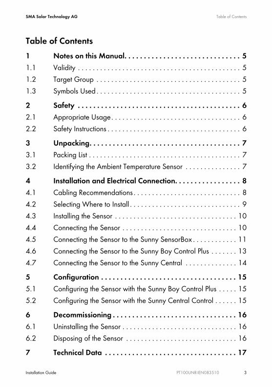
Table of Contents1 Notes on this Manual. . . . . . . . . . . . . . . . . . . . . . . . . . . . . . 51.1 Validity . . . . . . . . . . . . . . . . . . . . . . . . . . . . . . . . . . . . . . . . . . . . 51.2 Target Group . . . . . . . . . . . . . . . . . . . . . . . . . . . . . . . . . . . . . . . 51.3 Symbols Used . . . . . . . . . . . . . . . . . . . . . . . . . . . . . . . . . . . . . . . 52 Safety . . . . . . . . . . . . . . . . . . . . . . . . . . . . . . . . . . . . . . . . . . 62.1 Appropriate Usage. . . . . . . . . . . . . . . . . . . . . . . . . . . . . . . . . . . 62.2 Safety Instructions . . . . . . . . . . . . . . . . . . . . . . . . . . . . . . . . . . . . 63 Unpacking. . . . . . . . . . . . . . . . . . . . . . . . . . . . . . . . . . . . . . . 73.1 Packing List . . . . . . . . . . . . . . . . . . . . . . . . . . . . . . . . . . . . . . . . . 73.2 Identifying the Ambient Temperature Sensor . . . . . . . . . . . . . . . 74 Installation and Electrical Connection. . . . . . . . . . . . . . . . . 84.1 Cabling Recommendations . . . . . . . . . . . . . . . . . . . . . . . . . . . . . 84.2 Selecting Where to Install . . . . . . . . . . . . . . . . . . . . . . . . . . . . . . 94.3 Installing the Sensor . . . . . . . . . . . . . . . . . . . . . . . . . . . . . . . . . 104.4 Connecting the Sensor . . . . . . . . . . . . . . . . . . . . . . . . . . . . . . . 104.5 Connecting the Sensor to the Sunny SensorBox . . . . . . . . . . . . 114.6 Connecting the Sensor to the Sunny Boy Control Plus . . . . . . . 134.7 Connecting the Sensor to the Sunny Central . . . . . . . . . . . . . . 145 Configuration . . . . . . . . . . . . . . . . . . . . . . . . . . . . . . . . . . . 155.1 Configuring the Sensor with the Sunny Boy Control Plus . . . . . 155.2 Configuring the Sensor with the Sunny Central Control . . . . . . 156 Decommissioning . . . . . . . . . . . . . . . . . . . . . . . . . . . . . . . . 166.1 Uninstalling the Sensor . . . . . . . . . . . . . . . . . . . . . . . . . . . . . . . 166.2 Disposing of the Sensor . . . . . . . . . . . . . . . . . . . . . . . . . . . . . . 167 Technical Data . . . . . . . . . . . . . . . . . . . . . . . . . . . . . . . . . . 17
Table of Contents SMA Solar Technology AG
4 PT100UNR-IEN083510 Installation Guide
8 Accessories . . . . . . . . . . . . . . . . . . . . . . . . . . . . . . . . . . . . . 179 Contact . . . . . . . . . . . . . . . . . . . . . . . . . . . . . . . . . . . . . . . . 18
SMA Solar Technology AG Notes on this Manual
Installation Guide PT100UNR-IEN083510 5
1 Notes on this ManualThis manual describes how to install and commission the temperature sensor. Store this manual where it will be accessible at all times.
1.1 ValidityThis manual is valid for the PT100U-NR upgrade kit.
1.2 Target GroupThis manual is for qualified personnel.
1.3 Symbols UsedThe following types of safety instructions and general information appear in this document as described below.
DANGER!
DANGER indicates a safety instruction which, if not followed, will result in certain death or serious injury.WARNING!
WARNING indicates a safety instruction which, if not followed, could result in death or serious injury.CAUTION!
CAUTION indicates a safety instruction which, if not followed, could result in minor or moderate injury.ATTENTION!
ATTENTION indicates a safety instruction which, if not followed, could result in damage to property.Information'Information' provides valuable tips for the optimal operation of your product.
Safety SMA Solar Technology AG
6 PT100UNR-IEN083510 Installation Guide
2 Safety2.1 Appropriate UsageThe PT100U ambient temperature sensor consists of a PT100 measurement resistor which is installed in a lP65 plastic enclosure. The PT100U temperature sensor enables measurements in either a 2- or 4-wire system as desired. The measuring range of the ambient temperature sensor is between -30 °C and +80 °C. To process the ambient data, the sensor must be connected to the Sunny Boy Control Plus or the Sunny Central Control. The sensor is only suitable for use with original SMA accessories or with accessories recommended by SMA Solar Technology AG.Appropriate usage also includes observing all further documentation relating to this device and its components.
2.2 Safety InstructionsATTENTION!Damage to the sensors as a result of incorrect connection to the Sunny Boy Control Plus or Sunny Central Control.The Sunny Boy Control Plus installation guide and the wiring diagram provided must be used for establishing the electrical connections and connectors.
ATTENTION!Destruction of the PV system by a lightning strike.
All devices installed on a rooftop must be integrated into the existing lightning protection of the PV system.Overvoltage protectorProtect your PV system components against overvoltage from outside by connecting the sensors to an overvoltage protector. For using the sensors with the Sunny Central, the corresponding overvoltage protectors can be ordered as an option from Sunny Central.
SMA Solar Technology AG Unpacking
Installation Guide PT100UNR-IEN083510 7
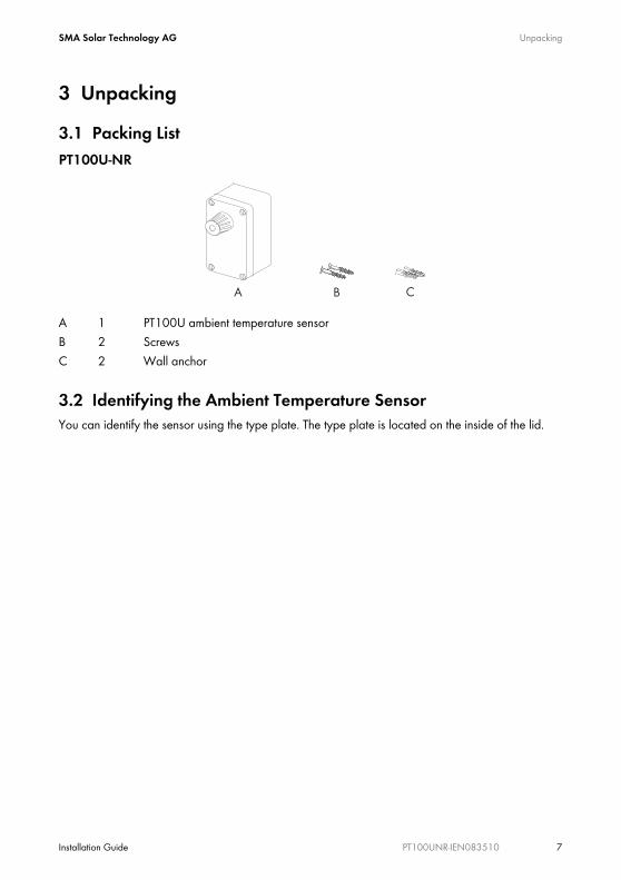
3 Unpacking3.1 Packing ListPT100U-NR
3.2 Identifying the Ambient Temperature SensorYou can identify the sensor using the type plate. The type plate is located on the inside of the lid.
A 1 PT100U ambient temperature sensorB 2 ScrewsC 2 Wall anchor
Installation and Electrical Connection SMA Solar Technology AG
8 PT100UNR-IEN083510 Installation Guide
4 Installation and Electrical ConnectionThe PT100U ambient temperature sensor can be connected to the Sunny Boy Control Plus or the Sunny Central Control via a 2- or 4-wire system as desired. The connection cable is not included and is routed into the enclosure interior via a cable gland.
4.1 Cabling RecommendationsThe cable length and quality will affect the signal quality. To achieve a good quality signal, observe the following cabling instructions:OutdoorsFor outdoors, use a cable with the following basic properties.
• Cross-section: min. 4 x 0.25mm², min. 4 x AWG 24• External cable diameter: min. 4.5mm, max. 7mm• UV-resistant
We recommend the following cable types:• Lapp cable: Unitronic S-LifY11Y 4 x 0.34mm², order no.: 7038 861• UL-listed Lapp cable: UNITRONIC S-LifY11Y 4 x 0.34mm², order no.: 7038 865
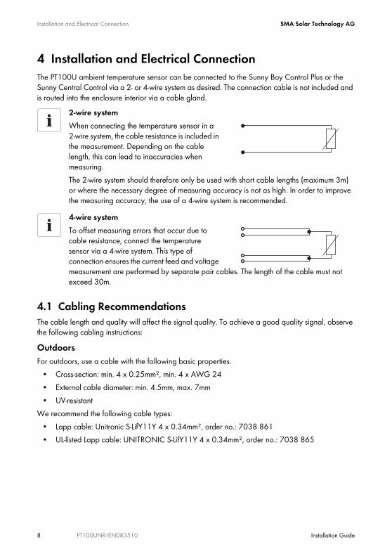
2-wire systemWhen connecting the temperature sensor in a 2-wire system, the cable resistance is included in the measurement. Depending on the cable length, this can lead to inaccuracies when measuring.The 2-wire system should therefore only be used with short cable lengths (maximum 3m) or where the necessary degree of measuring accuracy is not as high. In order to improve the measuring accuracy, the use of a 4-wire system is recommended.4-wire systemTo offset measuring errors that occur due to cable resistance, connect the temperature sensor via a 4-wire system. This type of connection ensures the current feed and voltage measurement are performed by separate pair cables. The length of the cable must not exceed 30m.
SMA Solar Technology AG Installation and Electrical Connection
Installation Guide PT100UNR-IEN083510 9
IndoorsIf you protect the cable against UV radiation for use outdoors by means of a suitable cable channel, you can also use a non-UV-resistant (indoor) cable with the basic properties mentioned above.We recommend the following cable types:
• Lapp cable: Unitronic LiYY 4 x 0.5mm², order no.: 0028 504• UL-listed Lapp cable: UNITRONIC LiYY UL/CSA 4 x AWG22/7, order no.: 0022 604• Helukabel: TRONIC LiYY 4 x 0.5mm², order no.: 18087
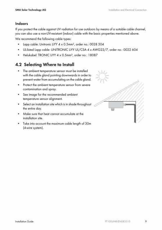
4.2 Selecting Where to Install• The ambient temperature sensor must be installed
with the cable gland pointing downwards in order to prevent water from accumulating on the cable gland.
• Protect the ambient temperature sensor from severe contamination and spray.
• See image for the recommended ambient temperature sensor alignment.
• Select an installation site which is in shade throughout the entire day.
• Make sure that heat cannot accumulate at the installation site.
• Take into account the maximum cable length of 30m (4-wire system).
Installation and Electrical Connection SMA Solar Technology AG
10 PT100UNR-IEN083510 Installation Guide
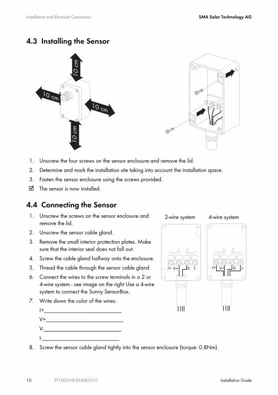
4.3 Installing the Sensor
1. Unscrew the four screws on the sensor enclosure and remove the lid.2. Determine and mark the installation site taking into account the installation space.3. Fasten the sensor enclosure using the screws provided.☑ The sensor is now installed.
4.4 Connecting the Sensor1. Unscrew the screws on the sensor enclosure and
remove the lid. 2. Unscrew the sensor cable gland.3. Remove the small interior protection plates. Make
sure that the interior seal does not fall out.4. Screw the cable gland halfway onto the enclosure.5. Thread the cable through the sensor cable gland.6. Connect the wires to the screw terminals in a 2 or
4-wire system - see image on the right Use a 4-wire system to connect the Sunny SensorBox.
7. Write down the color of the wires:I+__________________________V+__________________________V-__________________________I-__________________________
8. Screw the sensor cable gland tightly into the sensor enclosure (torque: 0.8Nm).
2-wire system 4-wire system
I+ V+ V- I- I+ V+ V- I-
SMA Solar Technology AG Installation and Electrical Connection
Installation Guide PT100UNR-IEN083510 11
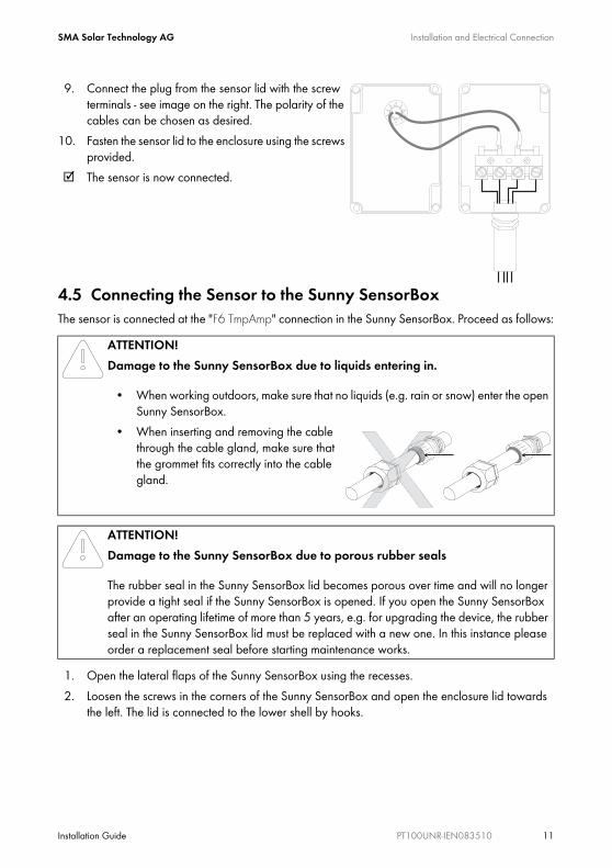
9. Connect the plug from the sensor lid with the screw terminals - see image on the right. The polarity of the cables can be chosen as desired.
10. Fasten the sensor lid to the enclosure using the screws provided.
☑ The sensor is now connected.
4.5 Connecting the Sensor to the Sunny SensorBoxThe sensor is connected at the "F6 TmpAmp" connection in the Sunny SensorBox. Proceed as follows:
1. Open the lateral flaps of the Sunny SensorBox using the recesses.2. Loosen the screws in the corners of the Sunny SensorBox and open the enclosure lid towards
the left. The lid is connected to the lower shell by hooks.
ATTENTION!Damage to the Sunny SensorBox due to liquids entering in.
• When working outdoors, make sure that no liquids (e.g. rain or snow) enter the open Sunny SensorBox.
• When inserting and removing the cable through the cable gland, make sure that the grommet fits correctly into the cable gland.
ATTENTION!Damage to the Sunny SensorBox due to porous rubber seals
The rubber seal in the Sunny SensorBox lid becomes porous over time and will no longer provide a tight seal if the Sunny SensorBox is opened. If you open the Sunny SensorBox after an operating lifetime of more than 5 years, e.g. for upgrading the device, the rubber seal in the Sunny SensorBox lid must be replaced with a new one. In this instance please order a replacement seal before starting maintenance works.
Installation and Electrical Connection SMA Solar Technology AG
12 PT100UNR-IEN083510 Installation Guide
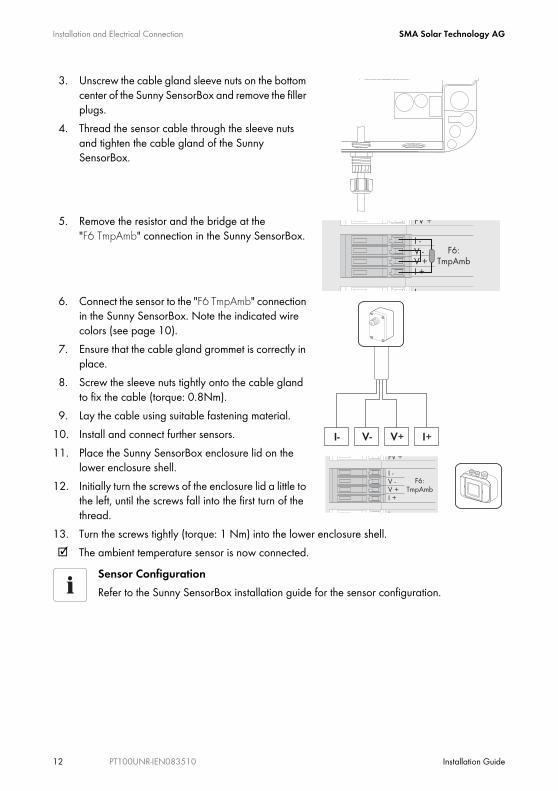
3. Unscrew the cable gland sleeve nuts on the bottom center of the Sunny SensorBox and remove the filler plugs.
4. Thread the sensor cable through the sleeve nuts and tighten the cable gland of the Sunny SensorBox.
5. Remove the resistor and the bridge at the "F6 TmpAmb" connection in the Sunny SensorBox.
6. Connect the sensor to the "F6 TmpAmb" connection in the Sunny SensorBox. Note the indicated wire colors (see page 10).
7. Ensure that the cable gland grommet is correctly in place.
8. Screw the sleeve nuts tightly onto the cable gland to fix the cable (torque: 0.8Nm).
9. Lay the cable using suitable fastening material.10. Install and connect further sensors.11. Place the Sunny SensorBox enclosure lid on the
lower enclosure shell.12. Initially turn the screws of the enclosure lid a little to
the left, until the screws fall into the first turn of the thread.
13. Turn the screws tightly (torque: 1 Nm) into the lower enclosure shell.☑ The ambient temperature sensor is now connected.
Sensor ConfigurationRefer to the Sunny SensorBox installation guide for the sensor configuration.
SMA Solar Technology AG Installation and Electrical Connection
Installation Guide PT100UNR-IEN083510 13
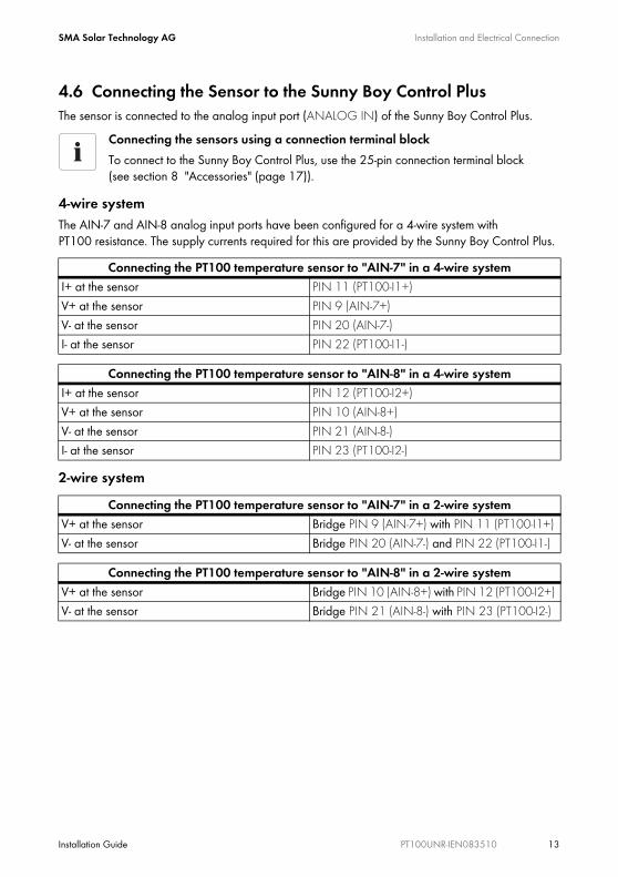
4.6 Connecting the Sensor to the Sunny Boy Control PlusThe sensor is connected to the analog input port (ANALOG IN) of the Sunny Boy Control Plus.
4-wire systemThe AIN-7 and AIN-8 analog input ports have been configured for a 4-wire system with PT100 resistance. The supply currents required for this are provided by the Sunny Boy Control Plus.
2-wire system
Connecting the sensors using a connection terminal blockTo connect to the Sunny Boy Control Plus, use the 25-pin connection terminal block (see section 8 "Accessories" (page 17)).
Connecting the PT100 temperature sensor to "AIN-7" in a 4-wire systemI+ at the sensor PIN 11 (PT100-I1+)V+ at the sensor PIN 9 (AIN-7+)V- at the sensor PIN 20 (AIN-7-)I- at the sensor PIN 22 (PT100-I1-)
Connecting the PT100 temperature sensor to "AIN-8" in a 4-wire systemI+ at the sensor PIN 12 (PT100-I2+)V+ at the sensor PIN 10 (AIN-8+)V- at the sensor PIN 21 (AIN-8-)I- at the sensor PIN 23 (PT100-I2-)
Connecting the PT100 temperature sensor to "AIN-7" in a 2-wire systemV+ at the sensor Bridge PIN 9 (AIN-7+) with PIN 11 (PT100-I1+) V- at the sensor Bridge PIN 20 (AIN-7-) and PIN 22 (PT100-I1-)
Connecting the PT100 temperature sensor to "AIN-8" in a 2-wire systemV+ at the sensor Bridge PIN 10 (AIN-8+) with PIN 12 (PT100-I2+) V- at the sensor Bridge PIN 21 (AIN-8-) with PIN 23 (PT100-I2-)
Installation and Electrical Connection SMA Solar Technology AG
14 PT100UNR-IEN083510 Installation Guide
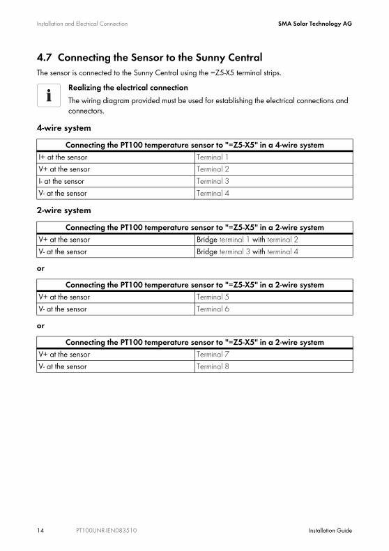
4.7 Connecting the Sensor to the Sunny CentralThe sensor is connected to the Sunny Central using the =Z5-X5 terminal strips.
4-wire system
2-wire system
or
or
Realizing the electrical connectionThe wiring diagram provided must be used for establishing the electrical connections and connectors.
Connecting the PT100 temperature sensor to "=Z5-X5" in a 4-wire systemI+ at the sensor Terminal 1V+ at the sensor Terminal 2I- at the sensor Terminal 3V- at the sensor Terminal 4
Connecting the PT100 temperature sensor to "=Z5-X5" in a 2-wire systemV+ at the sensor Bridge terminal 1 with terminal 2V- at the sensor Bridge terminal 3 with terminal 4
Connecting the PT100 temperature sensor to "=Z5-X5" in a 2-wire systemV+ at the sensor Terminal 5V- at the sensor Terminal 6
Connecting the PT100 temperature sensor to "=Z5-X5" in a 2-wire systemV+ at the sensor Terminal 7V- at the sensor Terminal 8
SMA Solar Technology AG Configuration
Installation Guide PT100UNR-IEN083510 15
5 Configuration
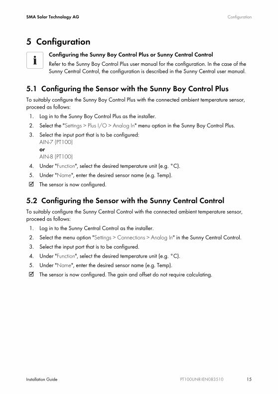
5.1 Configuring the Sensor with the Sunny Boy Control PlusTo suitably configure the Sunny Boy Control Plus with the connected ambient temperature sensor, proceed as follows:1. Log in to the Sunny Boy Control Plus as the installer.2. Select the "Settings > Plus I/O > Analog In" menu option in the Sunny Boy Control Plus.3. Select the input port that is to be configured:
AIN-7 (PT100) or AIN-8 (PT100)
4. Under "Function", select the desired temperature unit (e.g. °C).5. Under "Name", enter the desired sensor name (e.g. Temp).☑ The sensor is now configured.
5.2 Configuring the Sensor with the Sunny Central ControlTo suitably configure the Sunny Central Control with the connected ambient temperature sensor, proceed as follows:1. Log in to the Sunny Central Control as the installer.2. Select the menu option "Settings > Connections > Analog In" in the Sunny Central Control.3. Select the input port that is to be configured.4. Under "Function", select the desired temperature unit (e.g. °C).5. Under "Name", enter the desired sensor name (e.g. Temp).☑ The sensor is now configured. The gain and offset do not require calculating.
Configuring the Sunny Boy Control Plus or Sunny Central ControlRefer to the Sunny Boy Control Plus user manual for the configuration. In the case of the Sunny Central Control, the configuration is described in the Sunny Central user manual.
Decommissioning SMA Solar Technology AG
16 PT100UNR-IEN083510 Installation Guide
6 Decommissioning6.1 Uninstalling the Sensor1. Reset the sensor configuration in the communication device.2. Detach the sensor cable from the communication device.3. Unscrew the screws on the sensor enclosure and remove the lid.4. Remove the enclosure from the wall.☑ The sensor is now uninstalled.
6.2 Disposing of the SensorAt the end of its service life, dispose of the sensor in accordance with the applicable disposal regulations for electronic waste at the installation site at that time. Alternatively, send it back to SMA Solar Technology with shipping paid by the sender, and labeled "ZUR ENTSORGUNG" ("for disposal")
SMA Solar Technology AG Technical Data
Installation Guide PT100UNR-IEN083510 17
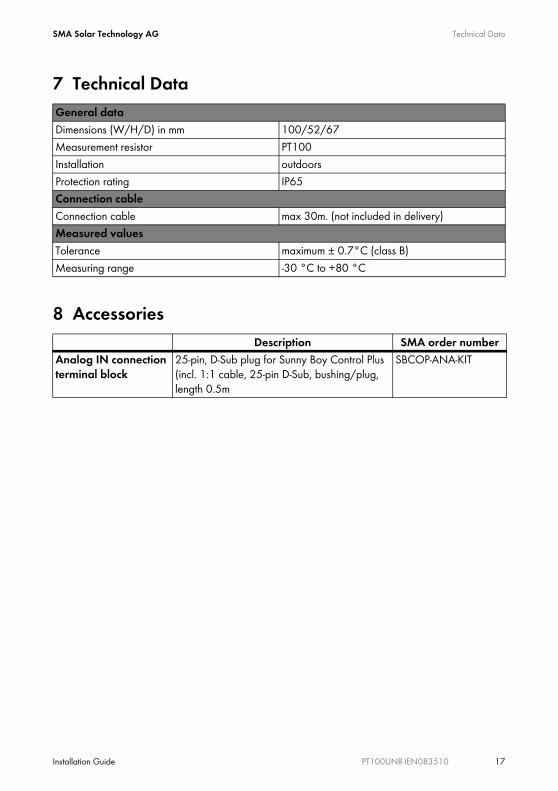
7 Technical Data
8 Accessories
General dataDimensions (W/H/D) in mm 100/52/67Measurement resistor PT100Installation outdoorsProtection rating IP65Connection cableConnection cable max 30m. (not included in delivery)Measured valuesTolerance maximum ± 0.7°C (class B)Measuring range -30 °C to +80 °C
Description SMA order numberAnalog IN connection terminal block
25-pin, D-Sub plug for Sunny Boy Control Plus (incl. 1:1 cable, 25-pin D-Sub, bushing/plug, length 0.5m
SBCOP-ANA-KIT
Contact SMA Solar Technology AG
18 PT100UNR-IEN083510 Installation Guide
9 ContactIf you have technical problems concerning our products, contact our Service Line. We need the following information to provide you with the necessary assistance:
• Sensor model• Communication device• Measured values
SMA Solar Technology AGSonnenallee 134266 Niestetal, Germanywww.SMA.de
Serviceline Inverters: +49 561 9522 1499Communication: +49 561 9522 2499Fax: +49 561 9522 4699E-Mail: [email protected]
Sunny CentralSMA Solar Technology AG Sonnenallee 134266 Niestetal, GermanyTel. +49 561 9522 299Fax +49 561 9522 3299 [email protected] www.SMA.de
SMA Solar Technology AG Legal Restrictions
Installation Guide PT100UNR-IEN083510 19
The information contained in this document is the property of SMA Solar Technology AG. Publishing its content, either partially or in full, requires the written permission of SMA Solar Technology AG. Any internal company copying of the document for the purposes of evaluating the product or its correct implementation is allowed and does not require permission.
Exclusion of liabilityThe general terms and conditions of delivery of SMA Solar Technology AG shall apply.The content of these documents is continually checked and amended, where necessary. However, discrepancies cannot be excluded. No guarantee is made for the completeness of these documents. The latest version is available online at www.SMA.de or from the usual sales channels.Guarantee or liability claims for damages of any kind are excluded if they are caused by one or more of the following: • Damages during transportation• Improper or inappropriate use of the product• Operating the product in an unintended environment• Operating the product whilst ignoring relevant, statutory safety regulations in the deployment location• Ignoring safety warnings and instructions contained in all documents relevant to the product• Operating the product under incorrect safety or protection conditions• Altering the product or supplied software without authority• The product malfunctions due to operating attached or neighboring devices beyond statutory limit values• In case of unforeseen calamity or force majeureThe use of supplied software produced by SMA Solar Technology AG is subject to the following conditions:• SMA Solar Technology AG rejects any liability for direct or indirect damages arising from the use of software developed by
SMA Solar Technology AG. This also applies to the provision or non-provision of support activities.• Supplied software not developed by SMA Solar Technology AG is subject to the respective licensing and liability agreements
of the manufacturer.
SMA Factory WarrantyThe current guarantee conditions come enclosed with your device. These are also available online at www.SMA.de and can be downloaded or are available on paper from the usual sales channels if required.
TrademarksAll trademarks are recognized even if these are not marked separately. Missing designations do not mean that a product or brand is not a registered trademark.The Bluetooth® word mark and logos are registered trademarks owned by Bluetooth SIG, Inc. and any use of such marks by SMA Solar Technology is under license.SMA Solar Technology AGSonnenallee 134266 NiestetalGermanyTel. +49 561 9522-0Fax +49 561 9522-100www.SMA.deE-Mail: [email protected]© 2004 to 2009 SMA Solar Technology AG. All rights reserved

SMA Solar Technology AG
Sonnenallee 1
34266 Niestetal, Germany
Tel.: +49 561 9522 4000
Fax: +49 561 9522 4040
E-Mail: [email protected]
Freecall: 0800 SUNNYBOY
Freecall: 0800 78669269
www.SMA.de