Embed Size (px)
Citation preview
INNOVATIVE SYSTEMS SOLUTIONS
USG
BO
RA
L.C
OM
H 2 INTRODUCTIONH 11 MULTIFRAME™H 14 SERVICES SEPARATIONH 15 PARTIWALL®H 18 INTRWALL®
MULTI-RESIDENTIAL
H
SYST
EMS+
April 2015 | USG Boral Systems+H 2
H MULTI-RESIDENTIAL
INTRODUCTION
USG Boral offers a range of BCA compliant fire and acoustic rated building systems for the Multi-Residential sector. These include:
• Partiwall® separating walls for Class 1 attached dwellings
• IntRwall® separating walls for Class 2 and 3 buildings with concrete slabs
• Multiframe™ timber framed construction system for low rise buildings Class 2 and 3.
A brief overview of the above systems and BCA requirements for Multi-Residential buildings is provided below. For more information on various systems refer to the relevant USG Boral publications and usgboral.com
BCA REQUIREMENTSNOTE
Extracts of BCA requirements provided below are intended for guidance only and should not be used as a substitute for professional advice. Refer to BCA for the full set of performance requirements for Multi-Residential buildings.
FIRE RESISTANCEFIRE RESISTANCE LEVELSIn accordance with BCA, certain elements in multi-residential buildings must achieve stipulated Fire Resistance Levels (FRL).
Class 1 BuildingsSeparating walls between Class 1 buildings (ie attached villa units and townhouses) must have an FRL of not less than 60/60/60.
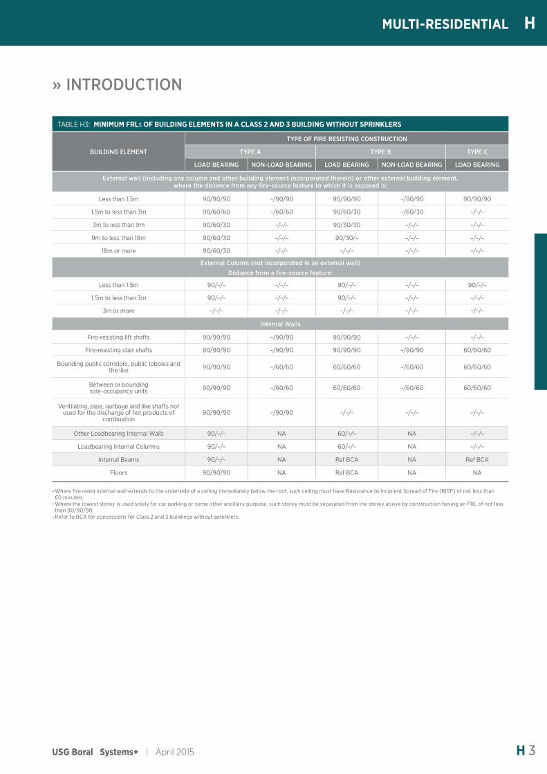
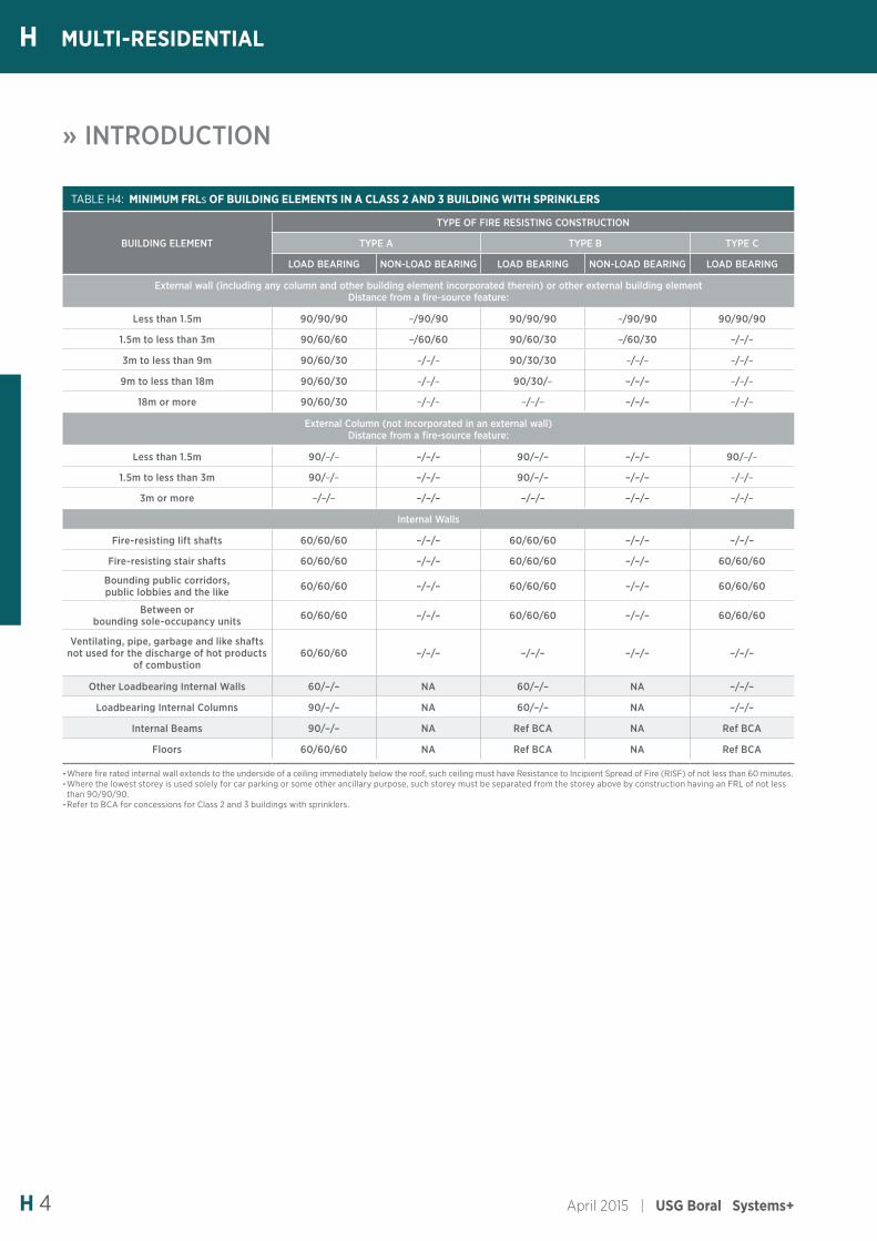
Class 2 and 3 BuildingsBuilding elements in Class 2 and 3 buildings (ie apartments, boarding houses, hotels) must have minimum FRLs depending the type of fire resisting construction ranging from Type A (the most fire resistant) to Type C (the least fire resistant):
TABLE H1: TYPES OF FIRE RESISTING CONSTRUCTION FOR CLASS 2 AND 3 BUILDINGS
RISE IN STOREYS TYPE OF CONSTRUCTION
4 or more A
3 A
2 B
1 C
Refer to BCA for: -Calculations of rise in storeys. -Treatment of buildings with multiple classifications. -Concession for Class 2 and 3 Buildings.
Minimum FRL’s for Class 2 and 3 buildings are outlined in
tables H3 and H4
Class 9c BuildingsRefer to the BCA for fire resistance requirements for Class 9c buildings.
FIRE HAZARD PROPERTIES OF LINING MATERIALSUnder the BCA, wall and ceiling lining materials are assigned a group number from Group 1 (best performing) to Group 4 (worst performing) based on their Fire Hazard Properties.
The following table outlines permitted group numbers of wall and ceiling lining materials in Class 2 buildings:
TABLE H2: PERMITTED GROUPS FOR WALL AND CEILING MATERIALS
CLASS OF BUILDING
FIRE-ISOLATED EXITS & FIRE
CONTROL ROOMS
PUBLIC CORRIDORS
SOLE OCCUPANCY
UNITS
OTHER AREAS
WALL/ CEILING WALL CEILING WALL CEILING WALL/
CEILING
Unsprinklered 1 1, 2 1, 2 1, 2, 3 1, 2, 3 1, 2, 3
Sprinklered 1 1, 2, 3 1, 2, 3 1, 2, 3 1, 2, 3 1, 2, 3
SMOKE-PROOF WALLSPublic corridors in Class 2 or 3 buildings must be divided at intervals of not more than 40m with smoke-proof walls complying with Specification C2.5 of BCA.
STRUCTURAL TESTS FOR LIGHTWEIGHT CONSTRUCTIONFire-resisting walls of lightweight construction must satisfy the structural test criteria outlined in Specification C1.8 of BCA.
NON-COMBUSTIBLE MATERIALSUnder Clause C1.12 of BCA, plasterboard is deemed to be a non-combustible material. Where Class 2 building is constructed using timber framing, insulation in the cavity of a fire-resisting wall must be non-combustible.
USG Boral Systems+ | April 2015 H 3
HMULTI-RESIDENTIAL
» INTRODUCTION
TABLE H3: MINIMUM FRLs OF BUILDING ELEMENTS IN A CLASS 2 AND 3 BUILDING WITHOUT SPRINKLERS
BUILDING ELEMENT
TYPE OF FIRE RESISTING CONSTRUCTION
TYPE A TYPE B TYPE C
LOAD BEARING NON-LOAD BEARING LOAD BEARING NON-LOAD BEARING LOAD BEARING
External wall (including any column and other building element incorporated therein) or other external building element, where the distance from any fire-source feature to which it is exposed is:
Less than 1.5m 90/90/90 –/90/90 90/90/90 –/90/90 90/90/90
1.5m to less than 3m 90/60/60 –/60/60 90/60/30 –/60/30 –/–/–
3m to less than 9m 90/60/30 –/–/– 90/30/30 –/–/– –/–/–
9m to less than 18m 90/60/30 –/–/– 90/30/– –/–/– –/–/–
18m or more 90/60/30 –/–/– –/–/– –/–/– –/–/–
External Column (not incorporated in an external wall)Distance from a fire-source feature:
Less than 1.5m 90/–/– –/–/– 90/–/– –/–/– 90/–/–
1.5m to less than 3m 90/–/– –/–/– 90/–/– –/–/– –/–/–
3m or more –/–/– –/–/– –/–/– –/–/– –/–/–
Internal Walls
Fire-resisting lift shafts 90/90/90 –/90/90 90/90/90 –/–/– –/–/–
Fire-resisting stair shafts 90/90/90 –/90/90 90/90/90 –/90/90 60/60/60
Bounding public corridors, public lobbies and the like 90/90/90 –/60/60 60/60/60 –/60/60 60/60/60
Between or bounding sole-occupancy units 90/90/90 –/60/60 60/60/60 –/60/60 60/60/60
Ventilating, pipe, garbage and like shafts not used for the discharge of hot products of
combustion90/90/90 –/90/90 –/–/– –/–/– –/–/–
Other Loadbearing Internal Walls 90/–/– NA 60/–/– NA –/–/–
Loadbearing Internal Columns 90/–/– NA 60/–/– NA –/–/–
Internal Beams 90/–/– NA Ref BCA NA Ref BCA
Floors 90/90/90 NA Ref BCA NA NA
-Where fire rated internal wall extends to the underside of a ceiling immediately below the roof, such ceiling must have Resistance to Incipient Spread of Fire (RISF) of not less than 60 minutes. -Where the lowest storey is used solely for car parking or some other ancillary purpose, such storey must be separated from the storey above by construction having an FRL of not less than 90/90/90. -Refer to BCA for concessions for Class 2 and 3 buildings without sprinklers.
April 2015 | USG Boral Systems+H 4
H MULTI-RESIDENTIAL
» INTRODUCTION
TABLE H4: MINIMUM FRLs OF BUILDING ELEMENTS IN A CLASS 2 AND 3 BUILDING WITH SPRINKLERS
BUILDING ELEMENT
TYPE OF FIRE RESISTING CONSTRUCTION
TYPE A TYPE B TYPE C
LOAD BEARING NON-LOAD BEARING LOAD BEARING NON-LOAD BEARING LOAD BEARING
External wall (including any column and other building element incorporated therein) or other external building element Distance from a fire-source feature:
Less than 1.5m 90/90/90 –/90/90 90/90/90 –/90/90 90/90/90
1.5m to less than 3m 90/60/60 –/60/60 90/60/30 –/60/30 –/–/–
3m to less than 9m 90/60/30 –/–/– 90/30/30 –/–/– –/–/–
9m to less than 18m 90/60/30 –/–/– 90/30/– –/–/– –/–/–
18m or more 90/60/30 –/–/– –/–/– –/–/– –/–/–
External Column (not incorporated in an external wall) Distance from a fire-source feature:
Less than 1.5m 90/–/– –/–/– 90/–/– –/–/– 90/–/–
1.5m to less than 3m 90/–/– –/–/– 90/–/– –/–/– –/–/–
3m or more –/–/– –/–/– –/–/– –/–/– –/–/–
Internal Walls
Fire-resisting lift shafts 60/60/60 –/–/– 60/60/60 –/–/– –/–/–
Fire-resisting stair shafts 60/60/60 –/–/– 60/60/60 –/–/– 60/60/60
Bounding public corridors, public lobbies and the like 60/60/60 –/–/– 60/60/60 –/–/– 60/60/60
Between or bounding sole-occupancy units 60/60/60 –/–/– 60/60/60 –/–/– 60/60/60
Ventilating, pipe, garbage and like shafts not used for the discharge of hot products
of combustion60/60/60 –/–/– –/–/– –/–/– –/–/–
Other Loadbearing Internal Walls 60/–/– NA 60/–/– NA –/–/–
Loadbearing Internal Columns 90/–/– NA 60/–/– NA –/–/–
Internal Beams 90/–/– NA Ref BCA NA Ref BCA
Floors 60/60/60 NA Ref BCA NA Ref BCA
-Where fire rated internal wall extends to the underside of a ceiling immediately below the roof, such ceiling must have Resistance to Incipient Spread of Fire (RISF) of not less than 60 minutes. -Where the lowest storey is used solely for car parking or some other ancillary purpose, such storey must be separated from the storey above by construction having an FRL of not less than 90/90/90. -Refer to BCA for concessions for Class 2 and 3 buildings with sprinklers.
USG Boral Systems+ | April 2015 H 5
HMULTI-RESIDENTIAL
» INTRODUCTION
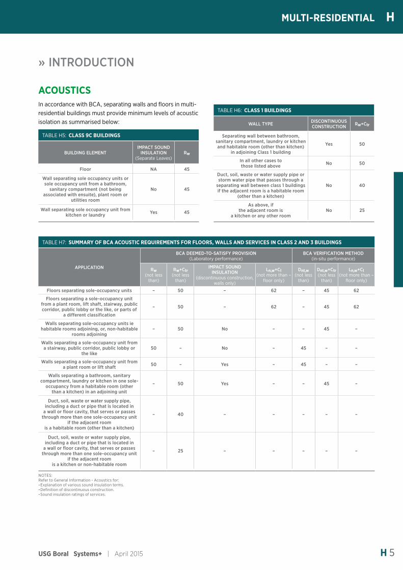
NOTES:Refer to General Information - Acoustics for: -Explanation of various sound insulation terms. -Definition of discontinuous construction. -Sound insulation ratings of services.
TABLE H7: SUMMARY OF BCA ACOUSTIC REQUIREMENTS FOR FLOORS, WALLS AND SERVICES IN CLASS 2 AND 3 BUILDINGS
APPLICATION
BCA DEEMED-TO-SATISFY PROVISION (Laboratory performance)
BCA VERIFICATION METHOD (in-situ performance)
Rw (not less
than)
Rw+Ctr (not less
than)
IMPACT SOUND INSULATION
(discontinuous construction, walls only)
Ln,w+CI (not more than –
floor only)
Dnt,w (not less
than)
Dnt,w+Ctr (not less
than)
Ln,w+CI (not more than –
floor only)
Floors separating sole-occupancy units – 50 – 62 – 45 62
Floors separating a sole-occupancy unit from a plant room, lift shaft, stairway, public corridor, public lobby or the like, or parts of
a different classification
– 50 – 62 – 45 62
Walls separating sole-occupancy units ie habitable rooms adjoining, or, non-habitable
rooms adjoining– 50 No – – 45 –
Walls separating a sole-occupancy unit from a stairway, public corridor, public lobby or
the like50 – No – 45 – –
Walls separating a sole-occupancy unit from a plant room or lift shaft 50 – Yes – 45 – –
Walls separating a bathroom, sanitary compartment, laundry or kitchen in one sole-
occupancy from a habitable room (other than a kitchen) in an adjoining unit
– 50 Yes – – 45 –
Duct, soil, waste or water supply pipe, including a duct or pipe that is located in
a wall or floor cavity, that serves or passes through more than one sole-occupancy unit
if the adjacent room is a habitable room (other than a kitchen)
– 40 – – – – –
Duct, soil, waste or water supply pipe, including a duct or pipe that is located in
a wall or floor cavity, that serves or passes through more than one sole-occupancy unit
if the adjacent room is a kitchen or non-habitable room
– 25 – – – – –
ACOUSTICSIn accordance with BCA, separating walls and floors in multi-residential buildings must provide minimum levels of acoustic isolation as summarised below:
TABLE H5: CLASS 9C BUILDINGS
BUILDING ELEMENTIMPACT SOUND
INSULATION (Separate Leaves)
Rw
Floor NA 45
Wall separating sole occupancy units or sole occupancy unit from a bathroom,
sanitary compartment (not being associated with ensuite), plant room or
utilities room
No 45
Wall separating sole occupancy unit from kitchen or laundry Yes 45
TABLE H6: CLASS 1 BUILDINGS
WALL TYPE DISCONTINUOUS CONSTRUCTION Rw+Ctr
Separating wall between bathroom, sanitary compartment, laundry or kitchen and habitable room (other than kitchen)
in adjoining Class 1 building
Yes 50
In all other cases to those listed above No 50
Duct, soil, waste or water supply pipe or storm water pipe that passes through a
separating wall between class 1 buildings if the adjacent room is a habitable room
(other than a kitchen)
No 40
As above, if the adjacent room is
a kitchen or any other roomNo 25
April 2015 | USG Boral Systems+H 6
H MULTI-RESIDENTIAL
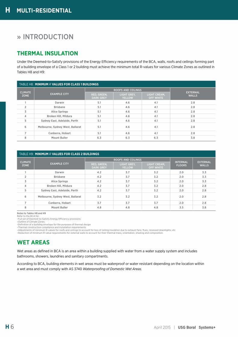
THERMAL INSULATIONUnder the Deemed-to-Satisfy provisions of the Energy Efficiency requirements of the BCA, walls, roofs and ceilings forming part of a building envelope of a Class 1 or 2 building must achieve the minimum total R-values for various Climate Zones as outlined in Tables H8 and H9:
» INTRODUCTION
TABLE H8: MINIMUM R VALUES FOR CLASS 1 BUILDINGS
CLIMATE ZONE EXAMPLE CITY
ROOFS AND CEILINGSEXTERNAL
WALLSRED, GREEN, DARK GREY
LIGHT GREY, YELLOW
LIGHT CREAM, OFF WHITE
1 Darwin 5.1 4.6 4.1 2.8
2 Brisbane 5.1 4.6 4.1 2.8
3 Alice Springs 5.1 4.6 4.1 2.8
4 Broken Hill, Mildura 5.1 4.6 4.1 2.8
5 Sydney East, Adelaide, Perth 5.1 4.6 4.1 2.8
6 Melbourne, Sydney West, Ballarat 5.1 4.6 4.1 2.8
7 Canberra, Hobart 5.1 4.6 4.1 2.8
8 Mount Buller 6.3 6.3 6.3 3.8
TABLE H9: MINIMUM R VALUES FOR CLASS 2 BUILDINGS
CLIMATE ZONE EXAMPLE CITY
ROOFS AND CEILINGSINTERNAL FLOORS
EXTERNAL WALLSRED, GREEN,
DARK GREYLIGHT GREY,
YELLOWLIGHT CREAM,
OFF WHITE
1 Darwin 4.2 3.7 3.2 2.0 3.3
2 Brisbane 4.2 3.7 3.2 2.0 3.3
3 Alice Springs 4.2 3.7 3.2 2.0 3.3
4 Broken Hill, Mildura 4.2 3.7 3.2 2.0 2.8
5 Sydney East, Adelaide, Perth 4.2 3.7 3.2 2.0 2.8
6 Melbourne, Sydney West, Ballarat 3.2 3.2 3.2 2.0 2.8
7 Canberra, Hobart 3.7 3.7 3.7 2.0 2.8
8 Mount Buller 4.8 4.8 4.8 3.5 3.8
Notes to Tables H8 and H9Refer to the BCA for: -Full set of Deemed-to-Satisfy Energy Efficiency provisions -Outline of Climate Zones -Definition of a building envelope for the purposes of thermal design -Thermal construction compliance and installation requirements -Adjustments of minimum R-values for roofs and ceilings to account for loss of ceiling insulation due to exhaust fans, flues, recessed downlights, etc -Reduction of minimum R-value requirements for external walls to account for their thermal mass, orientation, shading and composition.
WET AREASWet areas as defined in BCA is an area within a building supplied with water from a water supply system and includes bathrooms, showers, laundries and sanitary compartments.
According to BCA, building elements in wet areas must be waterproof or water resistant depending on the location within a wet area and must comply with AS 3740 Waterproofing of Domestic Wet Areas.
USG Boral Systems+ | April 2015 H 7
HMULTI-RESIDENTIAL
» INTRODUCTION
NOTE
Partiwall system is designed to provide fire protection to the adjacent dwelling and not to dwellings above or below. As such, Partiwall system is not suitable for use in timber framed Class 2 or 3 buildings.
DESIGN OPTIONSPartiwall systems are available in three basic fire rated configurations:
TABLE H10: PARTIWALL SYSTEM TYPES
SYSTEM TYPE FIRE BARRIER FRL
PWT60.1 1x25mm SHAFTLINER 60/60/60
PWT90.1 1x25mm SHAFTLINER + 1x16mm FIRESTOP 90/90/90
PWT90.2 2x25mm SHAFTLINER 90/90/90
All fire rated configurations are available with a wide range of outer linings, including hybrid linings with different impact and/or water resistance properties on each side of the wall.
All Partiwall systems listed in this manual achieve acoustic ratings equal to or exceeding Rw+Ctr= 50 and provide acoustic impact isolation as defined in the BCA (Discontinuous Construction).
While only timber framed Partiwall systems have been listed in this manual, Partiwall is also available in steel framed configurations. Contact USG Boral for more information.
MATERIALSFIRE BARRIER• 25mm Shaftliner
• 25mm H-studs or 50mm I-studs
• Rondo 25mm or 50mm steel track
• Partiwall aluminium clips
• USG Boral Firepack® mineral wool packer.
LININGS• 10mm/13mm Soundstop plasterboard
• 10mm/13mm Impactstop plasterboard
• 10mm/13mm Wet Area plasterboard
• 10mm Fiberock
• 6mm Villaboard® fibre cement.
USG BORAL MULTI-RESIDENTIAL SYSTEMS
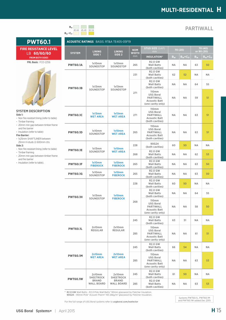
PARTIWALL®DESCRIPTIONUSG Boral Partiwall is a family of separating wall systems for Class 1 buildings.
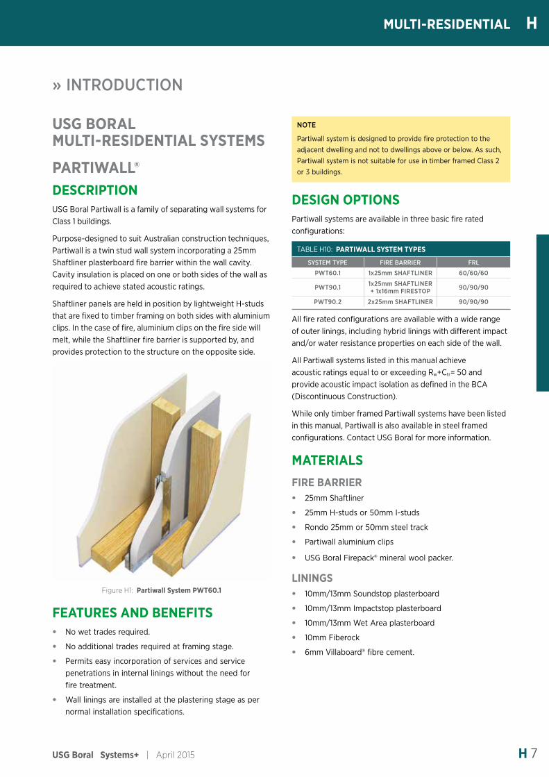
Purpose-designed to suit Australian construction techniques, Partiwall is a twin stud wall system incorporating a 25mm Shaftliner plasterboard fire barrier within the wall cavity. Cavity insulation is placed on one or both sides of the wall as required to achieve stated acoustic ratings.
Shaftliner panels are held in position by lightweight H-studs that are fixed to timber framing on both sides with aluminium clips. In the case of fire, aluminium clips on the fire side will melt, while the Shaftliner fire barrier is supported by, and provides protection to the structure on the opposite side.
Figure H1: Partiwall System PWT60.1
FEATURES AND BENEFITS• No wet trades required.
• No additional trades required at framing stage.
• Permits easy incorporation of services and service penetrations in internal linings without the need for fire treatment.
• Wall linings are installed at the plastering stage as per normal installation specifications.
April 2015 | USG Boral Systems+H 8
H MULTI-RESIDENTIAL
INSULATION• R2.0 Pink Wall Batts® 90mm glasswool by Fletcher Insulation
• 110mm USG Boral Partiwall Acoustic Batt
• 90mm Pink® Acousti-Therm® HD glasswool 24kg/m3 by Fletcher Insulation.
SEALANTH.B. Fuller Firesound sealant.
FASTENERSRefer Partiwall brochure for fastener types used in construction of Partiwall system.
DESIGN CONSIDERATIONSMAXIMUM HEIGHTS AND LOADS• Overall height of Shaftliner fire barrier must not
exceed 12.0m.
• Spacing between aluminium clips supporting H-studs or I-studs must not exceed 3.0m vertically and 600mm horizontally.
• Timber framing is to be designed for normal service conditions and must comply with AS 1684 Timber Framed Construction.
• Partiwall is suitable for wind classification N1 and N2 as determined by AS 4055 Wind Loads for Housing. Where Partiwall is proposed for higher wind classification areas contact USG Boral for advice.
FIRE RATING• Linings in the occupancy areas do not need be fire rated
and are constructed using the normal installation and finishing methods outlined in USG Boral Plasterboard Installation Manual.
• Normal service penetrations are allowed through outer linings and are not required to be fire rated.
• Service penetrations through Shaftliner fire barrier are allowed only in the roof space (refer Partiwall brochure for details of approved penetrations). There should be no other penetrations through the fire barrier.
• Use only the specified Partiwall aluminium clips to attach the H-studs or I-studs to framing members. Other than the clips, there should be no attachments to the fire barrier.
ACOUSTICS• All Partiwall systems outlined in this manual are covered
by acoustical opinion RT&A TE-405-05F19 from Acoustical Consultants Renzo Tonin & Assoc.
• Partiwall® satisfies BCA acoustic requirements for separating walls of Rw+Ctr=50 and acoustic impact isolation, and Rw+Ctr=25 and Rw+Ctr=40 acoustic separation of adjoining soil and waste pipes within the wall cavity. To maintain acoustic performance, service pipes must not be in contact with the Shaftliner fire barrier.
• Small penetrations in outer linings (ie switches, power points, light fittings and pipes) do not need to be acoustically sealed, however Shaftliner fire barrier base and internal lining junctions with floors must be sealed with H.B. Fuller Firesound sealant.
• Stair stringers and treads should be kept clear of the separating wall in order to reduce the likelihood of stair impact sound travelling through the wall.
WET AREASWet areas (as defined in the BCA) must be waterproofed as per the wet area details contained in USG Boral Installation Manual.
Partiwall Systems extending into wet areas must incorporate water resistant linings.
INSTALLATIONPartiwall system must be installed strictly in accordance with USG Boral installation specifications in order to achieve design fire and acoustic ratings. Refer to Partiwall brochure for installation specifications.
» INTRODUCTION
USG Boral Systems+ | April 2015 H 9
HMULTI-RESIDENTIAL
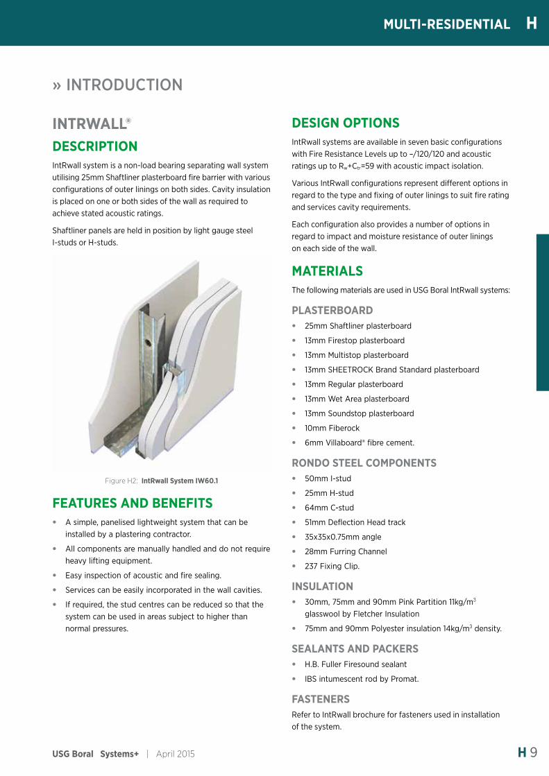
INTRWALL®DESCRIPTIONIntRwall system is a non-load bearing separating wall system utilising 25mm Shaftliner plasterboard fire barrier with various configurations of outer linings on both sides. Cavity insulation is placed on one or both sides of the wall as required to achieve stated acoustic ratings.
Shaftliner panels are held in position by light gauge steel I-studs or H-studs.
Figure H2: IntRwall System IW60.1
FEATURES AND BENEFITS• A simple, panelised lightweight system that can be
installed by a plastering contractor.
• All components are manually handled and do not require heavy lifting equipment.
• Easy inspection of acoustic and fire sealing.
• Services can be easily incorporated in the wall cavities.
• If required, the stud centres can be reduced so that the system can be used in areas subject to higher than normal pressures.
DESIGN OPTIONSIntRwall systems are available in seven basic configurations with Fire Resistance Levels up to –/120/120 and acoustic ratings up to Rw+Ctr=59 with acoustic impact isolation.
Various IntRwall configurations represent different options in regard to the type and fixing of outer linings to suit fire rating and services cavity requirements.
Each configuration also provides a number of options in regard to impact and moisture resistance of outer linings on each side of the wall.
MATERIALSThe following materials are used in USG Boral IntRwall systems:
PLASTERBOARD• 25mm Shaftliner plasterboard
• 13mm Firestop plasterboard
• 13mm Multistop plasterboard
• 13mm SHEETROCK Brand Standard plasterboard
• 13mm Regular plasterboard
• 13mm Wet Area plasterboard
• 13mm Soundstop plasterboard
• 10mm Fiberock
• 6mm Villaboard® fibre cement.
RONDO STEEL COMPONENTS• 50mm I-stud
• 25mm H-stud
• 64mm C-stud
• 51mm Deflection Head track
• 35x35x0.75mm angle
• 28mm Furring Channel
• 237 Fixing Clip.
INSULATION• 30mm, 75mm and 90mm Pink Partition 11kg/m3
glasswool by Fletcher Insulation
• 75mm and 90mm Polyester insulation 14kg/m3 density.
SEALANTS AND PACKERS• H.B. Fuller Firesound sealant
• IBS intumescent rod by Promat.
FASTENERSRefer to IntRwall brochure for fasteners used in installation of the system.
» INTRODUCTION
April 2015 | USG Boral Systems+H 10
H MULTI-RESIDENTIAL
DESIGN CONSIDERATIONSFIRE RATING• IntRwall system IW90.1A has been fire tested at CSIRO
laboratories at North Ryde in Sydney and system IW60.1B has been tested at Warrington Fire Research facility in Melbourne. Refer to IntRwall tables for fire test reports and assessments numbers for various IntRwall systems.
• Penetrations in single layer Shaftliner systems are not permitted.
• Services penetrations in double-layer Shaftliner fire barrier and/or fire resistant outer linings must be treated to maintain fire rating. Refer IntRwall brochure for details.
• Services penetrations in non-fire resistant outer linings are not required to be fire rated.
• Where IBS rod is specified in the top track, it must be installed in order to achieve the stated Fire Resistance Levels.
STRUCTURALThe IntRwall system has been tested in USG Boral NATA accredited laboratory in Port Melbourne and satisfies the requirements of the BCA Specification C1.8 to a maximum height of 3.0m. For greater wall heights refer to USG Boral.
System IW90.1 meets BCA serviceability requirements for walls of shafts and fire isolated exits (max deflection L/240 @ 350Pa lateral pressure). All IntRwall systems meet BCA requirements for walls generally (max deflection L/240 @ 250Pa lateral pressure).
For maximum heights of independent studs in IntRwall systems refer to Steel Stud Walls Lined One Side.
NOTE
In high-rise apartment construction, confirmation of internal design pressures should be obtained from the project Structural Engineer, especially where there are large openings such as sliding glass doors onto balconies. Consult USG Boral for stud sizes, heights and spacing for design pressures other than those specified above.
ACOUSTICSIntRwall system has been the subject of a series of acoustic tests at the CSIRO Acoustic Laboratory at Highett, Victoria.
All IntRwall systems outlined in this manual are covered by Acoustical Opinion RT&A TE405-05F20 from Acoustic Consultants Renzo Tonin & Assoc.
IntRwall systems with free standing framing on either side satisfy BCA Discontinuous Construction requirement where separating wall must provide impact sound isolation.
If services (duct, soil, waste or water supply pipe) are to be located within an IntRwall system and the adjacent dwelling is a habitable room (other than a kitchen), minimum construction on the adjacent dwelling’s side in order to achieve BCA acoustic isolation requirement of Rw+Ctr=40 must be as follows:
• 13mm Regular plasterboard (or heavier)
• 64mm free-standing studs
• 20mm gap between Shaftliner barrier and free standing studs
• 75mm Glasswool insulation 11kg/m3 or 75mm Polyester insulation 14kg/m3
All IntRwall systems achieve minimum Rw+Ctr=25 required for separation of services where the adjacent room is a kitchen or non-habitable room.
WET AREASWet areas (as defined in the BCA) must be waterproofed as per the wet area details contained in USG Boral Installation Manual.
IntRwall Systems extending into wet areas must incorporate water resistant linings.
LIMITATIONS• IntRwall is not suitable for use in lift shafts or in other
applications where it would be subjected to cyclical loading.
• Independent studs must be checked for pressure and other imposed loads (including shelf loads) as determined by the Project Structural Engineer.
• Penetrations in Shaftliner panels are not permitted unless it is a tested system. Contact USG Boral for further information.
INSTALLATIONIntRwall system must be installed strictly in accordance with USG Boral installation specification in order to achieve design fire and acoustic ratings. Refer to IntRwall brochure for installation specification and details.
» INTRODUCTION
USG Boral Systems+ | April 2015 H 11
HMULTI-RESIDENTIAL
MULTIFRAME™DESCRIPTIONMultiframe is a family of timber framed wall and ceiling systems satisfying BCA Fire Resistance and Acoustic requirements for low rise multi-residential buildings Class 2 and 3 (refer to BCA for height restrictions for timber framed Multi-Residential buildings).
DESIGN OPTIONSMultiframe includes a range of wall and ceiling systems as outlined below. Refer the relevant sections of this manual for configurations and acoustic ratings of various systems.
TABLE H11: SEPARATING WALLS
SYSTEM TYPE NON-LOAD BEARING FRL LOAD BEARING FRL
TT60.6 –/60/60 60/60/60
TT90.1 –/90/90 90/90/90
TT120.1 –/120/120 120/120/120
TABLE H12: CORRIDOR WALLS
SYSTEM TYPE NON-LOAD BEARING FRL LOAD BEARING FRL
TT60.6 –/60/60 60/60/60
TT90.1 –/90/90 90/90/90
TF90.1 –/90/90 90/90/90
TF120.1 –/120/120 120/120/120
TABLE H13: LOAD BEARING INTERNAL WALLS
SYSTEM TYPE NON-LOAD BEARING FRL LOAD BEARING FRL
TB90.1 –/90/90 90/90/90
TB120.1 –/120/120 120/120/120
TABLE H14: EXTERNAL WALLS - LIGHTWEIGHT
SYSTEM TYPE NON-LOAD BEARING FRL LOAD BEARING FRL
OWT.1 Non-fire rated Non fire rated
OWT30.1 NA 30/30/30
OWT60.2 NA 60/60/60
OWT90.1 NA 90/90/90 from outside only
OWT.90.3 NA 90/90/90
TABLE H15: EXTERNAL WALLS - BRICK VENEER
SYSTEM TYPE FRL FORM INSIDE FRL FROM OUTSIDE
BVT.1 –/–/– Brick veneer FRL as req’d
BV30.1 30/30/30 Brick veneer FRL 30/30/30
BV60.1 60/60/60 Brick veneer FRL 60/60/60
BV90.1 90/90/90 Brick veneer FRL 90/90/90
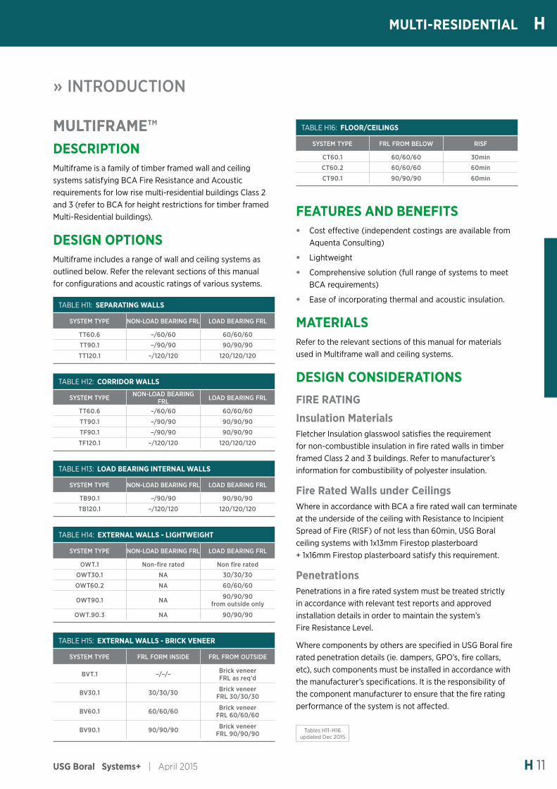
TABLE H16: FLOOR/CEILINGS
SYSTEM TYPE FRL FROM BELOW RISF
CT60.1 60/60/60 30min
CT60.2 60/60/60 60min
CT90.1 90/90/90 60min
FEATURES AND BENEFITS• Cost effective (independent costings are available from
Aquenta Consulting)
• Lightweight
• Comprehensive solution (full range of systems to meet BCA requirements)
• Ease of incorporating thermal and acoustic insulation.
MATERIALSRefer to the relevant sections of this manual for materials used in Multiframe wall and ceiling systems.
DESIGN CONSIDERATIONSFIRE RATING
Insulation MaterialsFletcher Insulation glasswool satisfies the requirement for non-combustible insulation in fire rated walls in timber framed Class 2 and 3 buildings. Refer to manufacturer’s information for combustibility of polyester insulation.
Fire Rated Walls under CeilingsWhere in accordance with BCA a fire rated wall can terminate at the underside of the ceiling with Resistance to Incipient Spread of Fire (RISF) of not less than 60min, USG Boral ceiling systems with 1x13mm Firestop plasterboard + 1x16mm Firestop plasterboard satisfy this requirement.
PenetrationsPenetrations in a fire rated system must be treated strictly in accordance with relevant test reports and approved installation details in order to maintain the system’s Fire Resistance Level.
Where components by others are specified in USG Boral fire rated penetration details (ie. dampers, GPO’s, fire collars, etc), such components must be installed in accordance with the manufacturer’s specifications. It is the responsibility of the component manufacturer to ensure that the fire rating performance of the system is not affected.
» INTRODUCTION
Tables H11-H16 updated Dec 2015
April 2015 | USG Boral Systems+H 12
H MULTI-RESIDENTIAL
» INTRODUCTION
ACOUSTICS
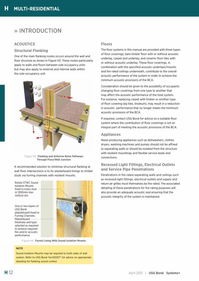
Structural FlankingOne of the main flanking routes occurs around the wall and floor structure as shown in Figure H3. These routes particularly apply to walls and floors between sole occupancy units but may also apply to external and internal walls within the sole-occupancy unit.
Figure H3: Flanking and Airborne Noise Pathways Through Floor/Wall Junction
A recommended solution to minimise structural flanking at wall floor intersections is to fix plasterboard linings to timber studs via furring channels with resilient mounts.
Figure H4: Furred Lining With Sound Isolation Mounts
NOTE:
Sound Isolation Mounts may be required to both sides of wall system. Refer to USG Boral TecASSIST® for advice on appropriate detailing for flanking sound control.
FloorsThe floor systems in this manual are provided with three types of floor coverings; bare timber floor with or without acoustic underlay, carpet and underlay, and ceramic floor tiles with or without acoustic underlay. These floor coverings, in combination with the specified acoustic underlays/mounts and fire rated ceilings underneath, contribute to the overall acoustic performance of the system in order to achieve the minimum acoustic provisions of the BCA.
Consideration should be given to the possibility of occupants changing floor coverings from one type to another that may affect the acoustic performance of the total system. For instance, replacing carpet with timber or another type of floor covering (eg tiles, linoleum), may result in a reduction in acoustic performance that no longer meets the minimum acoustic provisions of the BCA.
If required, contact USG Boral for advice on a suitable floor system where the contribution of floor coverings is not an integral part of meeting the acoustic provisions of the BCA.
AppliancesNoise producing appliances such as dishwashers, clothes dryers, washing machines and pumps should not be affixed to separating walls or should be isolated from the structure with resilient mountings and flexible service leads and connections.
Recessed Light Fittings, Electrical Outlets and Service Pipe PenetrationsPenetrations in fire rated separating walls and ceilings such as recessed light fittings, electrical outlets and supply and return air grilles must themselves be fire rated. The associated detailing of these penetrations for fire rating purposes will also provide an adequate acoustic seal ensuring that the acoustic integrity of the system is maintained.
USG Boral Systems+ | April 2015 H 13
HMULTI-RESIDENTIAL
» INTRODUCTION
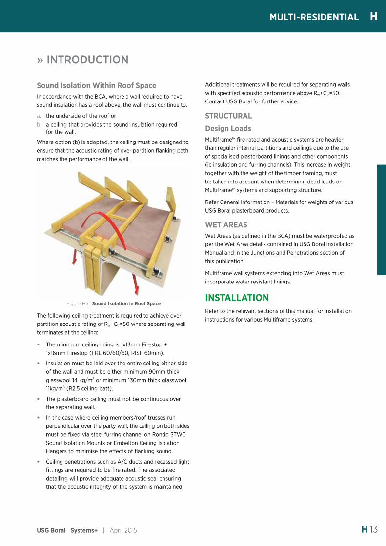
Sound Isolation Within Roof SpaceIn accordance with the BCA, where a wall required to have sound insulation has a roof above, the wall must continue to:
a. the underside of the roof or
b. a ceiling that provides the sound insulation required for the wall.
Where option (b) is adopted, the ceiling must be designed to ensure that the acoustic rating of over partition flanking path matches the performance of the wall.
Figure H5: Sound Isolation in Roof Space
The following ceiling treatment is required to achieve over partition acoustic rating of Rw+Ctr=50 where separating wall terminates at the ceiling:
• The minimum ceiling lining is 1x13mm Firestop + 1x16mm Firestop (FRL 60/60/60, RISF 60min).
• Insulation must be laid over the entire ceiling either side of the wall and must be either minimum 90mm thick glasswool 14 kg/m3 or minimum 130mm thick glasswool, 11kg/m3 (R2.5 ceiling batt).
• The plasterboard ceiling must not be continuous over the separating wall.
• In the case where ceiling members/roof trusses run perpendicular over the party wall, the ceiling on both sides must be fixed via steel furring channel on Rondo STWC Sound Isolation Mounts or Embelton Ceiling Isolation Hangers to minimise the effects of flanking sound.
• Ceiling penetrations such as A/C ducts and recessed light fittings are required to be fire rated. The associated detailing will provide adequate acoustic seal ensuring that the acoustic integrity of the system is maintained.
Additional treatments will be required for separating walls with specified acoustic performance above Rw+Ctr=50. Contact USG Boral for further advice.
STRUCTURAL
Design LoadsMultiframe™ fire rated and acoustic systems are heavier than regular internal partitions and ceilings due to the use of specialised plasterboard linings and other components (ie insulation and furring channels). This increase in weight, together with the weight of the timber framing, must be taken into account when determining dead loads on Multiframe™ systems and supporting structure.
Refer General Information – Materials for weights of various USG Boral plasterboard products.
WET AREASWet Areas (as defined in the BCA) must be waterproofed as per the Wet Area details contained in USG Boral Installation Manual and in the Junctions and Penetrations section of this publication.
Multiframe wall systems extending into Wet Areas must incorporate water resistant linings.
INSTALLATIONRefer to the relevant sections of this manual for installation instructions for various Multiframe systems.
April 2015 | USG Boral Systems+H 14
H MULTI-RESIDENTIAL
» INTRODUCTION
SERVICES SEPARATIONAs demonstrated in Table H17, fire rated linings of USG Boral Multiframe systems incorporating lagged or unlagged pipes meet or exceed the minimum BCA requirement of Rw+Ctr=25 and Rw+Ctr=40 respectively:
-
TABLE H17: Rw+Ctr ACOUSTIC RATINGS OF USG BORAL MULTIFRAME™ PLASTERBOARD LININGS
PLASTERBOARD LINING CONFIGURATION
UNLAGGED PIPES
LAGGED/CLAD PIPES
1x16mm Firestop 30 40
1x16mm Firestop + 1x10mm Regular 32 42
2x13mm Firestop 33 42
1x13mm Firestop + 1x16mm Firestop® 34 42
2x16mm Firestop 34 43
For lagged and clad pipes, any insulation that is listed as part of the system assembly is acceptable. -Acoustic ratings based on pipe lagged and clad with Soundlag 4525C from Pyrotek Noise Control or similar.
Designers should be aware of the reduction in acoustic performance of wall and ceiling linings due to penetrations such as downlights, exhaust grills, etc.
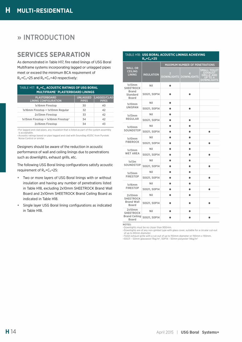
The following USG Boral lining configurations satisfy acoustic requirement of Rw+Ctr=25:
• Two or more layers of USG Boral linings with or without insulation and having any number of penetrations listed in Table H18, excluding 2x10mm SHEETROCK Brand Wall Board and 2x10mm SHEETROCK Brand Ceiling Board as indicated in Table H18.
• Single layer USG Boral lining configurations as indicated in Table H18.
TABLE H18: USG BORAL ACOUSTIC LININGS ACHIEVING Rw+Ctr=25
WALL OR CEILING LINING INSULATION
MAXIMUM NUMBER OF PENETRATIONS
2 DOWNLIGHTS
4 DOWNLIGHTS
SMALL TOILET EXHAUST
GRILLE AND UP TO 4
DOWNLIGHTS
1x13mm SHEETROCK
Brand Standard
Board
Nil •50G11, 50P14 • •
1x10mm UNISPAN
Nil •50G11, 50P14 • •
1x13mm REGULAR
Nil •50G11, 50P14 • •
1x10mm SOUNDSTOP
Nil • •50G11, 50P14 • • •
1x10mm FIBEROCK
Nil • •50G11, 50P14 • • •
1x13mm WET AREA
Nil • •50G11, 50P14 • • •
1x13m SOUNDSTOP
Nil • •50G11, 50P14 • • •
1x13mm FIRESTOP
Nil • •50G11, 50P14 • • •
1x16mm FIRESTOP
Nil • •50G11, 50P14 • • •
2x10mm SHEETROCK Brand Wall
Board
Nil • •50G11, 50P14 • • •
2x10mm SHEETROCK Brand Ceiling
Board
Nil • •50G11, 50P14 • • •
NOTES: -Downlights must be no closer than 900mm. -Downlights are of any non-gimbal type with glass cover, suitable for a circular cut-out of up to 80mm diameter. -Toilet exhaust grille with a cut-out of up to 150mm diameter or 150mm x 150mm. -50G11 – 50mm glasswool 11kg/m3, 50P14 – 50mm polyester 14kg/m3
Rw40-44 45-49 50-54
Rw+Ctr
HMULTI-RESIDENTIAL
USG Boral Systems+ | April 2015 H 15
ACOUSTIC RATINGS BASIS: RT&A TE405-05F19
SYSTEM LINING SIDE 1
LINING SIDE 2
NOM WIDTH
mm
STUD SIZE (GAP) mm 70 (20) 70 (40)
or 90 (20)
INSULATION* Rw Rw+Ctr Rw Rw+Ctr
PWT60.1A 1x10mm SOUNDSTOP
1x10mm SOUNDSTOP 265
R2.0 GW Wall Batts
(both cavities)NA NA 63 50
PWT60.1B 1x13mm SOUNDSTOP
1x13mm SOUNDSTOP
231R2.0 GW
Wall Batts (both cavities)
62 52 NA NA
271
R2.0 GW Wall Batts
(both cavities)NA NA 64 55
110mm USG Boral
PARTIWALL Acoustic Batt
(one cavity only)
NA NA 59 51
PWT60.1C 1x13mm WET AREA
1x13mm WET AREA 271
110mm USG Boral
PARTIWALL Acoustic Batt (both cavities)
NA NA 63 51
PWT60.1D 1x10mm SOUNDSTOP
1x10mm WET AREA 265
110mm USG Boral
PARTIWALL Acoustic Batt (both cavities)
NA NA 63 51
PWT60.1E 1x13mm SOUNDSTOP
1x10mm WET AREA
228 90G24 (both cavities) 60 50 NA NA
268R2.0 GW
Wall Batts (both cavities)
NA NA 62 53
PWT60.1F 1x10mm FIBEROCK
1x10mm FIBEROCK 265
R2.0 GW Wall Batts
(both cavities)NA NA 63 50
PWT60.1G 1x10mm SOUNDSTOP
1x10mm FIBEROCK 265
R2.0 GW Wall Batts
(both cavities)NA NA 63 50
PWT60.1H 1x13mm SOUNDSTOP
1x10mm FIBEROCK
228R2.0 GW
Wall Batts (both cavities)
60 50 NA NA
268
R2.0 GW Wall Batts
(both cavities)NA NA 64 55
110mm USG Boral
PARTIWALL Acoustic Batt
(one cavity only)
NA NA 58 50
PWT60.1L 2x10mm REGULAR
2x10mm REGULAR
245R2.0 GW
Wall Batts (both cavities)
63 51 NA NA
285
110mm USG Boral
PARTIWALL Acoustic Batt
(one cavity only)
NA NA 61 51
PWT60.1M 2x10mm WET AREA
2x10mm WET AREA
245R2.0 GW
Wall Batts (both cavities)
66 54 NA NA
285
110mm USG Boral
PARTIWALL Acoustic Batt
(one cavity only)
NA NA 63 53
PWT60.1W2x10mm
SHEETROCK BRAND
WALL BOARD
2x10mm SHEETROCK
BRAND WALL BOARD
245R2.0 GW
Wall Batts (both cavities)
61 50 NA NA
285R2.0 GW
Wall Batts (both cavities)
NA NA 63 53
SYSTEM DESCRIPTIONSide 1: - Non fire resistant lining (refer to table) - Timber framing - 20mm min gap between timber frame and fire barrier
- Insulation (refer to table)Fire Barrier: - 1x25mm SHAFTLINER between 25mm H-studs @ 600mm ctrs
Side 2: - Non fire resistant lining (refer to table) - Timber framing - 20mm min gap between timber frame and fire barrier
- Insulation (refer to table).
PWT60.1FIRE RESISTANCE LEVEL
LB 60/60/60FROM BOTH SIDES
PARTIWALL
For the full range of USG Boral systems refer to usgboral.com/eselector
* R2.0 GW Wall Batts - R2.0 Pink Wall Batts® 90mm glasswool by Fletcher Insulation. 90G24 – 90mm Pink® Acousti-Therm® HD 24kg/m3 glasswool by Fletcher Insulation.
FRL Basis: FCO-2256
HMULTI-RESIDENTIAL
Systems PWT60.1L, PWT60.1M and PWT60.1W added Dec 2015
Rw40-44 45-49 50-54
Rw+Ctr
H MULTI-RESIDENTIAL
April 2015 | USG Boral Systems+H 16
ACOUSTIC RATINGS BASIS: RT&A TE405-05F19
SYSTEM LINING SIDE 1
LINING SIDE 2
NOM WIDTH
mm
STUD SIZE (GAP) mm 70 (20) 70 (40)
or 90 (20)
INSULATION* Rw Rw+Ctr Rw Rw+Ctr
PWT90.1A 1x10mm REGULAR
1x10mm REGULAR 285
R2.0 GW Wall Batts
(both cavities)NA NA 63 50
PWT90.1B 1x10mm SOUNDSTOP
1x10mm SOUNDSTOP
245R2.0 GW
Wall Batts (both cavities)
64 52 NA NA
285R2.0 GW
Wall Batts (both cavities)
NA NA 67 55
PWT90.1C 1x13mm SOUNDSTOP
1x13mm SOUNDSTOP 290
R2.0 GW Wall Batts
(one cavity only)NA NA 62 50
PWT90.1D 1x10mm WET AREA
1x10mm WET AREA 285
R2.0 GW Wall Batts
(both cavities)NA NA 64 51
PWT90.1E 1x10mm REGULAR
1x10mm WET AREA 285
R2.0 GW Wall Batts
(both cavities)NA NA 63 50
PWT90.1F 1x10mm SOUNDSTOP
1x10mm WET AREA 285
R2.0 GW Wall Batts
(both cavities)NA NA 64 51
PWT90.1G 1x13mm SOUNDSTOP
1x10mm WET AREA
245R2.0 GW
Wall Batts (both cavities)
63 53 NA NA
285R2.0 GW
Wall Batts (one cavity only)
NA NA 59 50
PWT90.1H 1x10mm FIBEROCK
1x10mm FIBEROCK
245R2.0 GW
Wall Batts (both cavities)
64 52 NA NA
285R2.0 GW
Wall Batts (both cavities)
NA NA 67 55
PWT90.1I 1x10mm REGULAR
1x10mm FIBEROCK 285
R2.0 GW Wall Batts
(both cavities)NA NA 64 51
PWT90.1J 1x10mm SOUNDSTOP
1x10mm FIBEROCK
245R2.0 GW
Wall Batts (both cavities)
64 52 NA NA
285R2.0 GW
Wall Batts (both cavities)
NA NA 67 55
PWT90.1K 1x13mm SOUNDSTOP
1x10mm FIBEROCK 285
R2.0 GW Wall Batts
(one cavity only)NA NA 61 52
PWT90.1L 1x6mm VILLABOARD
1x6mm VILLABOARD 275
R2.0 GW Wall Batts
(both cavities)NA NA 66 53
PWT90.1M 1x10mm REGULAR
1x6mm VILLABOARD 280
R2.0 GW Wall Batts
(both cavities)NA NA 63 50
PWT90.1N 1x10mm SOUNDSTOP
1x6mm VILLABOARD 280
R2.0 GW Wall Batts
(both cavities)NA NA 66 53
110mm USG Boral
PARTIWALL Acoustic Batt
(one cavity only)
NA NA 62 50
PWT90.1AA
1x13mm SHEETROCK
BRAND STANDARD
BOARD
1x13mm SHEETROCK
BRAND STANDARD
BOARD
290R2.0 GW
Wall Batts (both cavities)
NA NA 65 52
PWT90.1AB
1x13mm SHEETROCK
BRAND STANDARD
BOARD
1x13mm WET AREA 290
R2.0 GW Wall Batts
(one cavity only)NA NA 67 54
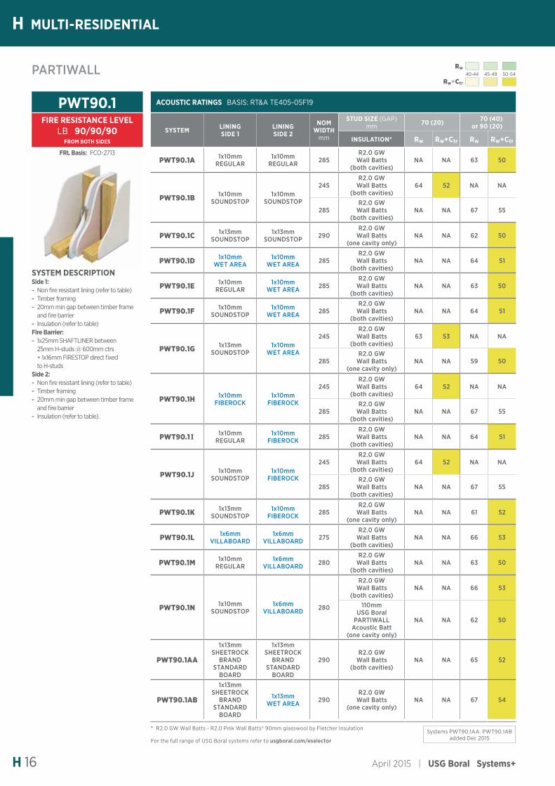
SYSTEM DESCRIPTIONSide 1: - Non fire resistant lining (refer to table) - Timber framing - 20mm min gap between timber frame and fire barrier
- Insulation (refer to table)Fire Barrier: - 1x25mm SHAFTLINER between 25mm H-studs @ 600mm ctrs + 1x16mm FIRESTOP direct fixed to H-studs
Side 2: - Non fire resistant lining (refer to table) - Timber framing - 20mm min gap between timber frame and fire barrier
- Insulation (refer to table).
PWT90.1FIRE RESISTANCE LEVEL
LB 90/90/90FROM BOTH SIDES
PARTIWALL
For the full range of USG Boral systems refer to usgboral.com/eselector
* R2.0 GW Wall Batts - R2.0 Pink Wall Batts® 90mm glasswool by Fletcher Insulation
FRL Basis: FCO-2713
Systems PWT90.1AA. PWT90.1AB added Dec 2015
Rw40-44 45-49 50-54
Rw+Ctr
HMULTI-RESIDENTIAL
USG Boral Systems+ | April 2015 H 17
ACOUSTIC RATINGS BASIS: RT&A TE405-05F19
SYSTEM LINING SIDE 1
LINING SIDE 2
NOM WIDTH
mm
STUD SIZE (GAP) mm 70 (20) 70 (40)
or 90 (20)
INSULATION* Rw Rw+Ctr Rw Rw+Ctr
PWT90.2A 1x10mm REGULAR
1x10mm REGULAR 290 R2.0 GW Wall Batts
(both cavities) NA NA 64 51
PWT90.2B 1x10mm SOUNDSTOP
1x10mm SOUNDSTOP
250 R2.0 GW Wall Batts (both cavities) 64 52 NA NA
290
R2.0 GW Wall Batts (both cavities) NA NA 68 56
110mm USG Boral PARTIWALL
Acoustic Batt (one cavity only)
NA NA 62 51
PWT90.2C 1x13mm SOUNDSTOP
1x13mm SOUNDSTOP 296 R2.0 GW Wall Batts
(one cavity only) NA NA 62 50
PWT90.2D 1x10mm WET AREA
1x10mm WET AREA 290 R2.0 GW Wall Batts
(both cavities) NA NA 64 51
PWT90.2E 1x10mm REGULAR
1x10mm WET AREA 290 R2.0 GW Wall Batts
(both cavities) NA NA 64 51
PWT90.2F 1x10mm SOUNDSTOP
1x10mm WET AREA 290 R2.0 GW Wall Batts
(both cavities) NA NA 65 52
PWT90.2G 1x13mm SOUNDSTOP
1x10mm WET AREA
253 R2.0 GW Wall Batts (both cavities) 64 54 NA NA
293 R2.0 GW Wall Batts (one cavity only) NA NA 60 51
PWT90.2H 1x13mm SOUNDSTOP
1x13mm WET AREA
256 R2.0 GW Wall Batts (both cavities) 66 56 NA NA
296 R2.0 GW Wall Batts (one cavity only) NA NA 62 53
PWT90.2I 1x10mm FIBEROCK
1x10mm FIBEROCK
250 R2.0 GW Wall Batts (both cavities) 64 52 NA NA
290
R2.0 GW Wall Batts (both cavities) NA NA 68 56
110mm USG Boral PARTIWALL
Acoustic Batt (one cavity only)
NA NA 62 51
PWT90.2J 1x10mm REGULAR
1x10mm FIBEROCK 290 R2.0 GW Wall Batts
(both cavities) NA NA 64 51
PWT90.2K 1x10mm SOUNDSTOP
1x10mm FIBEROCK
250 R2.0 GW Wall Batts (both cavities) 64 52 NA NA
290
R2.0 GW Wall Batts (both cavities) NA NA 68 56
110mm USG Boral PARTIWALL
Acoustic Batt (one cavity only)
NA NA 62 51
PWT90.2L 1x13mm SOUNDSTOP
1x10mm FIBEROCK 293 R2.0 GW Wall Batts
(one cavity only) NA NA 62 53
PWT90.2M 1x6mm VILLABOARD
1x6mm VILLABOARD
242 R2.0 GW Wall Batts (both cavities) 64 50 NA NA
282 R2.0 GW Wall Batts (both cavities) NA NA 68 55
PWT90.2N 1x10mm REGULAR
1x6mm VILLABOARD 286 R2.0 GW Wall Batts
(both cavities) NA NA 65 52
PWT90.2AB1x10mm
SHEETROCK BRAND
WALL BOARD
1x10mm SHEETROCK
BRAND WALL BOARD
290
110mm USG Boral PARTIWALL
Acoustic Batts (both cavities)
NA NA 63 50
PWT90.2AC1x10mm
SHEETROCK BRAND
WALL BOARD
1x10mm WET AREA 290
110mm USG Boral PARTIWALL
Acoustic Batts (both cavities)
NA NA 64 52
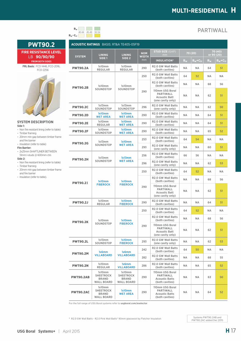
SYSTEM DESCRIPTIONSide 1: - Non fire resistant lining (refer to table) - Timber framing - 20mm min gap between timber frame and fire barrier
- Insulation (refer to table)Fire Barrier: - 2x25mm SHAFTLINER BETWEEN 51mm I-studs @ 600mm ctrs
Side 2: - Non fire resistant lining (refer to table) - Timber framing - 20mm min gap between timber frame and fire barrier
- Insulation (refer to table).
PWT90.2FIRE RESISTANCE LEVEL
LB 90/90/90FROM BOTH SIDES
PARTIWALL
For the full range of USG Boral systems refer to usgboral.com/eselector
* R2.0 GW Wall Batts - R2.0 Pink Wall Batts® 90mm glasswool by Fletcher Insulation
FRL Basis: FCO-1446, FCO-2016, FCO-2256
Systems PWT90.2AB and PWT90.2AC added Dec 2015
Rw40-44 45-49 50-54
Rw+Ctr
H MULTI-RESIDENTIAL
April 2015 | USG Boral Systems+H 18
INTRWALL
ACOUSTIC RATINGS BASIS: RT&A TE405-05F20
SYSTEM LINING SIDE 1
LINING SIDE 2
NOM WALL WIDTH (GAP)
mmINSULATION* Rw Rw+Ctr
IW60.1A1x13mm
SHEETROCK BRAND STANDARD
1x13mm SHEETROCK
BRAND STANDARD161 (20) 75G11, 75P14
(stud cavity) 55 46
IW60.1B 1x13mm REGULAR
1x13mm REGULAR 177 (36) 90G11, 90P14
(stud cavity) 59 51
IW60.1C 1x13mm SOUNDSTOP
1x13mm SOUNDSTOP 161 (20) 75G11, 75P14
(stud cavity) 60 51
IW60.1D 1x13mm WET AREA
1x13mm WET AREA 177 (36) 90G11, 90P14
(stud cavity) 60 51
IW60.1E 1x13mm WET AREA
1x13mm SHEETROCK
BRAND STANDARD177 (36) 90G11, 90P14
(stud cavity) 59 51
IW60.1F 1x13mm WET AREA
1x13mm REGULAR 177 (36) 90G11, 90P14
(stud cavity) 60 51
IW60.1G 1x13mm WET AREA
1x13mm SOUNDSTOP 177 (36) 90G11, 90P14
(stud cavity) 60 51
IW60.1H 1x13mm FIBEROCK
1x13mm FIBEROCK 171 (36) 90G11, 90P14
(stud cavity) 61 53
IW60.1I 1x13mm FIBEROCK
1x13mm SHEETROCK
BRAND STANDARD177 (36) 90G11, 90P14
(stud cavity) 60 52
IW60.1J 1x13mm FIBEROCK
1x13mm REGULAR 177 (36) 90G11, 90P14
(stud cavity) 61 52
IW60.1K 1x13mm FIBEROCK
1x13mm SOUNDSTOP 177 (36) 90G11, 90P14
(stud cavity) 61 53
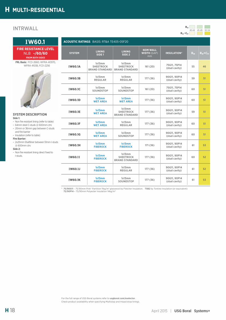
SYSTEM DESCRIPTIONSide 1: - Non fire resistant lining (refer to table) - 64mm steel C-studs @ 600mm ctrs - 20mm or 36mm gap between C-studs and fire barrier
- Insulation (refer to table)Fire Barrier: - 2x25mm Shaftliner between 51mm I-studs @ 600mm ctrs
Side 2: - Non fire resistant lining direct fixed to I-studs.
IW60.1FIRE RESISTANCE LEVEL
NLB -/60/60FROM BOTH SIDES
* 75/90G11 – 75/90mm Pink® Partition 11kg/m3 glasswool by Fletcher Insulation. TSB2 by Tontine Insulation (or equivalent) 75/90P14 – 75/90mm Polyester Insulation 14kg/m3
FRL Basis: FCO-2660, WFRA 40970, WFRA 41038, FCO-2256
For the full range of USG Boral systems refer to usgboral.com/eselector.Check product availability when specifying Multistop and Impactstop linings.
Rw40-44 45-49 50-54
Rw+Ctr
HMULTI-RESIDENTIAL
USG Boral Systems+ | April 2015 H 19
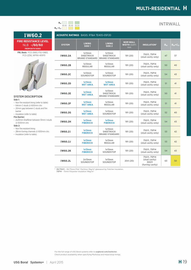
ACOUSTIC RATINGS BASIS: RT&A TE405-05F20
SYSTEM LINING SIDE 1
LINING SIDE 2
NOM WALL WIDTH (GAP)
mmINSULATION* Rw Rw+Ctr
IW60.2A1x13mm
SHEETROCK BRAND STANDARD
1x13mm SHEETROCK
BRAND STANDARD191 (20) 75G11, 75P14
(stud cavity only) 47 37
IW60.2B 1x13mm REGULAR
1x13mm REGULAR 191 (20) 75G11, 75P14
(stud cavity only) 50 40
IW60.2C 1x13mm SOUNDSTOP
1x13mm SOUNDSTOP 191 (20) 75G11, 75P14
(stud cavity only) 54 43
IW60.2D 1x13mm WET AREA
1x13mm WET AREA 191 (20) 75G11, 75P14
(stud cavity only) 51 41
IW60.2E 1x13mm WET AREA
1x13mm SHEETROCK
BRAND STANDARD191 (20) 75G11, 75P14
(stud cavity only) 50 41
IW60.2F 1x13mm WET AREA
1x13mm REGULAR 191 (20) 75G11, 75P14
(stud cavity only) 51 41
IW60.2G 1x13mm WET AREA
1x13mm SOUNDSTOP 191 (20) 75G11, 75P14
(stud cavity only) 52 40
IW60.2H 1x13mm FIBEROCK
1x13mm FIBEROCK 191 (20) 75G11, 75P14
(stud cavity only) 54 43
IW60.2I 1x13mm FIBEROCK
1x13mm SHEETROCK
BRAND STANDARD191 (20) 75G11, 75P14
(stud cavity only) 53 42
IW60.2J 1x13mm FIBEROCK
1x13mm REGULAR 191 (20) 75G11, 75P14
(stud cavity only) 53 42
IW60.2K 1x13mm FIBEROCK
1x13mm SOUNDSTOP 191 (20) 75G11, 75P14
(stud cavity only) 54 43
IW60.2L 2x13mm SOUNDSTOP
1x13mm SOUNDSTOP 204 (20)
75G11, 75P14 (stud cavity)
30G11 (furring cavity)
63 50
INTRWALL
SYSTEM DESCRIPTIONSide 1: - Non fire resistant lining (refer to table) - 64mm C-studs @ 600mm ctrs - 20mm gap between C-studs and fire barrier
- Insulation (refer to table)Fire Barrier: - 2x25mm Shaftliner between 51mm I-studs @ 600mm ctrs
Side 2: - Non fire resistant lining - 28mm furring channels @ 600mm ctrs - Insulation (refer to table).
IW60.2FIRE RESISTANCE LEVEL
NLB -/60/60FROM BOTH SIDES
* 30/75G11 – 30/75mm Pink® Partition 11kg/m3 glasswool by Fletcher Insulation. 75P14 – 75mm Polyester Insulation 14kg/m3
FRL Basis: FCO-2660, FSU-0883, FCO-2256, WFRA 40970
For the full range of USG Boral systems refer to usgboral.com/eselector.Check product availability when specifying Multistop and Impactstop linings.
Rw40-44 45-49 50-54
Rw+Ctr
H MULTI-RESIDENTIAL
April 2015 | USG Boral Systems+H 20
INTRWALL
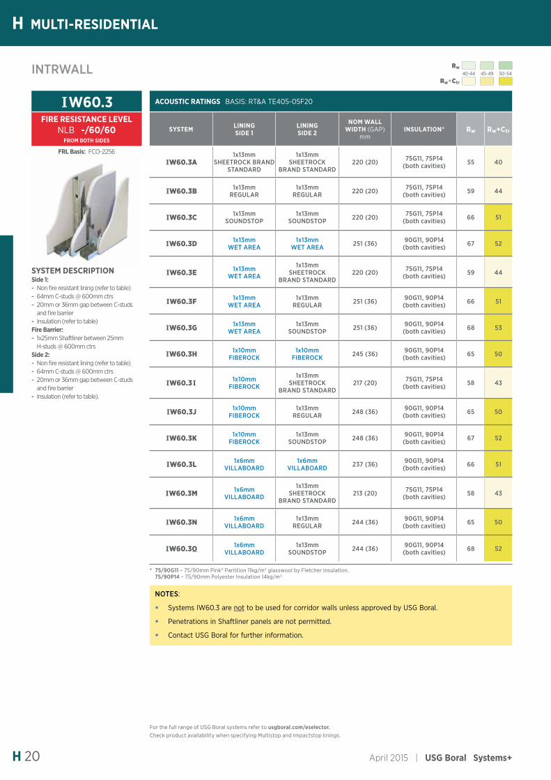
ACOUSTIC RATINGS BASIS: RT&A TE405-05F20
SYSTEM LINING SIDE 1
LINING SIDE 2
NOM WALL WIDTH (GAP)
mmINSULATION* Rw Rw+Ctr
IW60.3A1x13mm
SHEETROCK BRAND STANDARD
1x13mm SHEETROCK
BRAND STANDARD220 (20) 75G11, 75P14
(both cavities) 55 40
IW60.3B 1x13mm REGULAR
1x13mm REGULAR 220 (20) 75G11, 75P14
(both cavities) 59 44
IW60.3C 1x13mm SOUNDSTOP
1x13mm SOUNDSTOP 220 (20) 75G11, 75P14
(both cavities) 66 51
IW60.3D 1x13mm WET AREA
1x13mm WET AREA 251 (36) 90G11, 90P14
(both cavities) 67 52
IW60.3E 1x13mm WET AREA
1x13mm SHEETROCK
BRAND STANDARD220 (20) 75G11, 75P14
(both cavities) 59 44
IW60.3F 1x13mm WET AREA
1x13mm REGULAR 251 (36) 90G11, 90P14
(both cavities) 66 51
IW60.3G 1x13mm WET AREA
1x13mm SOUNDSTOP 251 (36) 90G11, 90P14
(both cavities) 68 53
IW60.3H 1x10mm FIBEROCK
1x10mm FIBEROCK 245 (36) 90G11, 90P14
(both cavities) 65 50
IW60.3I 1x10mm FIBEROCK
1x13mm SHEETROCK
BRAND STANDARD217 (20) 75G11, 75P14
(both cavities) 58 43
IW60.3J 1x10mm FIBEROCK
1x13mm REGULAR 248 (36) 90G11, 90P14
(both cavities) 65 50
IW60.3K 1x10mm FIBEROCK
1x13mm SOUNDSTOP 248 (36) 90G11, 90P14
(both cavities) 67 52
IW60.3L 1x6mm VILLABOARD
1x6mm VILLABOARD 237 (36) 90G11, 90P14
(both cavities) 66 51
IW60.3M 1x6mm VILLABOARD
1x13mm SHEETROCK
BRAND STANDARD213 (20) 75G11, 75P14
(both cavities) 58 43
IW60.3N 1x6mm VILLABOARD
1x13mm REGULAR 244 (36) 90G11, 90P14
(both cavities) 65 50
IW60.3O 1x6mm VILLABOARD
1x13mm SOUNDSTOP 244 (36) 90G11, 90P14
(both cavities) 68 52
SYSTEM DESCRIPTIONSide 1: - Non fire resistant lining (refer to table) - 64mm C-studs @ 600mm ctrs - 20mm or 36mm gap between C-studs and fire barrier
- Insulation (refer to table)Fire Barrier: - 1x25mm Shaftliner between 25mm H-studs @ 600mm ctrs
Side 2: - Non fire resistant lining (refer to table) - 64mm C-studs @ 600mm ctrs - 20mm or 36mm gap between C-studs and fire barrier
- Insulation (refer to table).
IW60.3FIRE RESISTANCE LEVEL
NLB -/60/60FROM BOTH SIDES
* 75/90G11 – 75/90mm Pink® Partition 11kg/m3 glasswool by Fletcher Insulation. 75/90P14 – 75/90mm Polyester Insulation 14kg/m3
FRL Basis: FCO-2256
NOTES:
• Systems IW60.3 are not to be used for corridor walls unless approved by USG Boral.
• Penetrations in Shaftliner panels are not permitted.
• Contact USG Boral for further information.
For the full range of USG Boral systems refer to usgboral.com/eselector.Check product availability when specifying Multistop and Impactstop linings.
Rw40-44 45-49 50-54
Rw+Ctr
HMULTI-RESIDENTIAL
USG Boral Systems+ | April 2015 H 21
* 75G11 – 75mm Pink® Partition 11kg/m3 glasswool by Fletcher Insulation. 75P14 – 75mm Polyester Insulation 14kg/m3
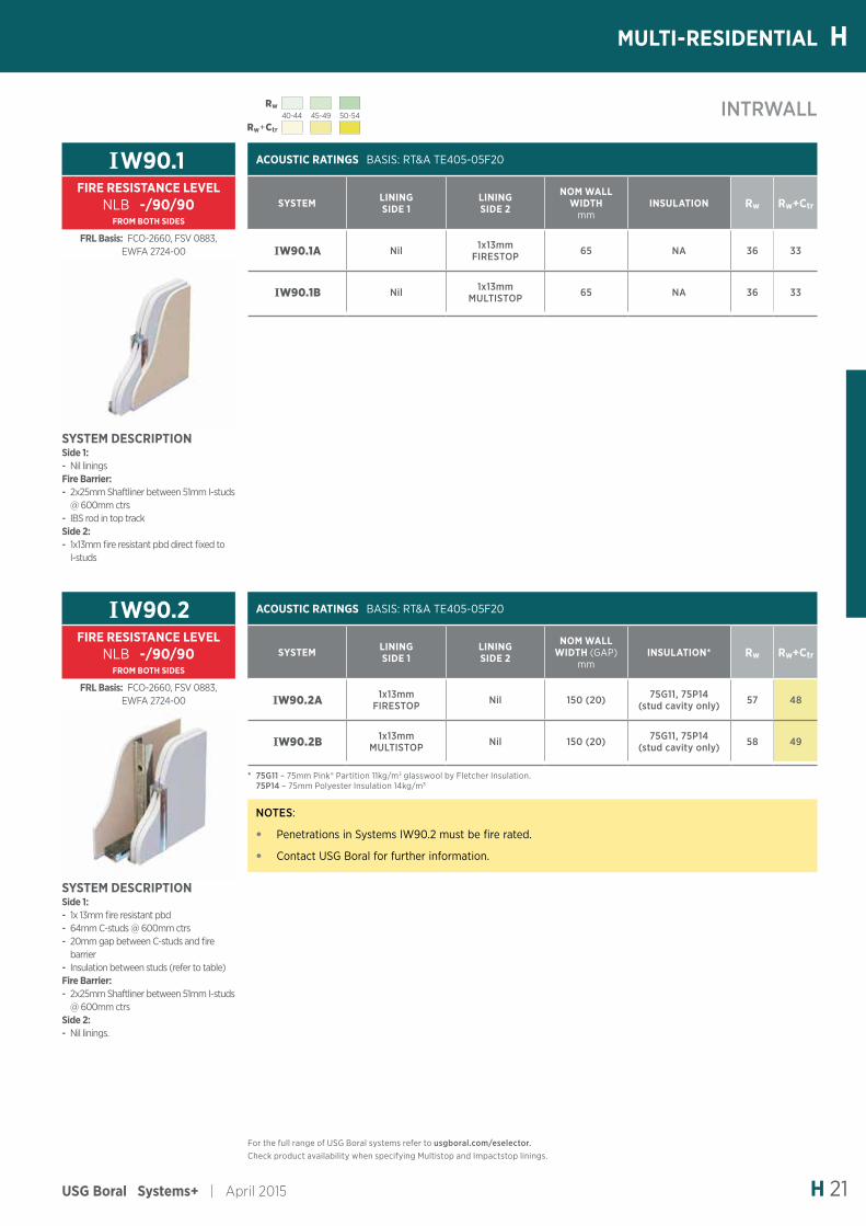
ACOUSTIC RATINGS BASIS: RT&A TE405-05F20
SYSTEM LINING SIDE 1
LINING SIDE 2
NOM WALL WIDTH
mmINSULATION Rw Rw+Ctr
IW90.1A Nil 1x13mm FIRESTOP 65 NA 36 33
IW90.1B Nil 1x13mm MULTISTOP 65 NA 36 33
ACOUSTIC RATINGS BASIS: RT&A TE405-05F20
SYSTEM LINING SIDE 1
LINING SIDE 2
NOM WALL WIDTH (GAP)
mmINSULATION* Rw Rw+Ctr
IW90.2A 1x13mm FIRESTOP Nil 150 (20) 75G11, 75P14
(stud cavity only) 57 48
IW90.2B 1x13mm MULTISTOP Nil 150 (20) 75G11, 75P14
(stud cavity only) 58 49
SYSTEM DESCRIPTIONSide 1: - Nil linings
Fire Barrier: - 2x25mm Shaftliner between 51mm I-studs @ 600mm ctrs
- IBS rod in top trackSide 2: - 1x13mm fire resistant pbd direct fixed to I-studs
SYSTEM DESCRIPTIONSide 1: - 1x 13mm fire resistant pbd - 64mm C-studs @ 600mm ctrs - 20mm gap between C-studs and fire barrier
- Insulation between studs (refer to table)Fire Barrier: - 2x25mm Shaftliner between 51mm I-studs @ 600mm ctrs
Side 2: - Nil linings.
IW90.1FIRE RESISTANCE LEVEL
NLB -/90/90FROM BOTH SIDES
IW90.2FIRE RESISTANCE LEVEL
NLB -/90/90FROM BOTH SIDES
INTRWALL
FRL Basis: FCO-2660, FSV 0883, EWFA 2724-00
FRL Basis: FCO-2660, FSV 0883, EWFA 2724-00
NOTES:
• Penetrations in Systems IW90.2 must be fire rated.
• Contact USG Boral for further information.
For the full range of USG Boral systems refer to usgboral.com/eselector.Check product availability when specifying Multistop and Impactstop linings.
Rw40-44 45-49 50-54
Rw+Ctr
H MULTI-RESIDENTIAL
April 2015 | USG Boral Systems+H 22
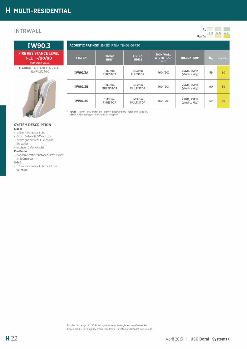
ACOUSTIC RATINGS BASIS: RT&A TE405-05F20
SYSTEM LINING SIDE 1
LINING SIDE 2
NOM WALL WIDTH (GAP)
mmINSULATION* Rw Rw+Ctr
IW90.3A 1x13mm FIRESTOP
1x13mm FIRESTOP 160 (20) 75G11, 75P14
(stud cavity) 59 50
IW90.3B 1x13mm MULTISTOP
1x13mm MULTISTOP 160 (20) 75G11, 75P14
(stud cavity) 60 51
IW90.3C 1x13mm FIRESTOP
1x13mm MULTISTOP 160 (20) 75G11, 75P14
(stud cavity) 59 50
SYSTEM DESCRIPTIONSide 1: - 1x 13mm fire resistant pbd - 64mm C-studs @ 600mm ctrs - 20mm gap between C-studs and fire barrier
- Insulation (refer to table)Fire Barrier: - 2x25mm Shaftliner between 51mm I-studs @ 600mm ctrs
Side 2: - 1x 13mm fire resistant pbd direct fixed to I-studs.
IW90.3FIRE RESISTANCE LEVEL
NLB -/90/90FROM BOTH SIDES
INTRWALL
* 75G11 – 75mm Pink® Partition 11kg/m3 glasswool by Fletcher Insulation. 75P14 – 75mm Polyester Insulation 14kg/m3
FRL Basis: FCO-2660, FCO-2434, EWFA 2724-00
For the full range of USG Boral systems refer to usgboral.com/eselector.Check product availability when specifying Multistop and Impactstop linings.
Rw40-44 45-49 50-54
Rw+Ctr
HMULTI-RESIDENTIAL
USG Boral Systems+ | April 2015 H 23
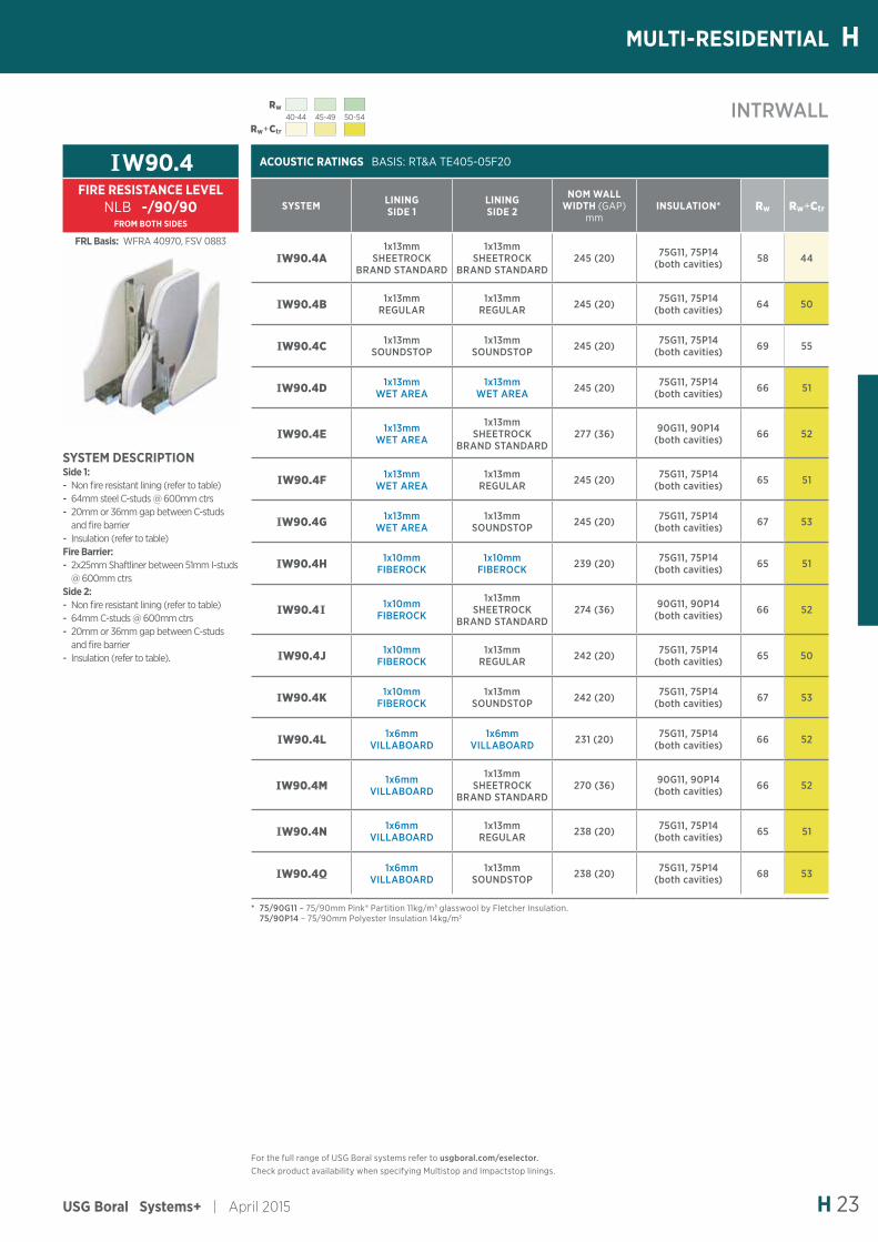
INTRWALL
ACOUSTIC RATINGS BASIS: RT&A TE405-05F20
SYSTEM LINING SIDE 1
LINING SIDE 2
NOM WALL WIDTH (GAP)
mmINSULATION* Rw Rw+Ctr
IW90.4A1x13mm
SHEETROCK BRAND STANDARD
1x13mm SHEETROCK
BRAND STANDARD245 (20) 75G11, 75P14
(both cavities) 58 44
IW90.4B 1x13mm REGULAR
1x13mm REGULAR 245 (20) 75G11, 75P14
(both cavities) 64 50
IW90.4C 1x13mm SOUNDSTOP
1x13mm SOUNDSTOP 245 (20) 75G11, 75P14
(both cavities) 69 55
IW90.4D 1x13mm WET AREA
1x13mm WET AREA 245 (20) 75G11, 75P14
(both cavities) 66 51
IW90.4E 1x13mm WET AREA
1x13mm SHEETROCK
BRAND STANDARD277 (36) 90G11, 90P14
(both cavities) 66 52
IW90.4F 1x13mm WET AREA
1x13mm REGULAR 245 (20) 75G11, 75P14
(both cavities) 65 51
IW90.4G 1x13mm WET AREA
1x13mm SOUNDSTOP 245 (20) 75G11, 75P14
(both cavities) 67 53
IW90.4H 1x10mm FIBEROCK
1x10mm FIBEROCK 239 (20) 75G11, 75P14
(both cavities) 65 51
IW90.4I 1x10mm FIBEROCK
1x13mm SHEETROCK
BRAND STANDARD274 (36) 90G11, 90P14
(both cavities) 66 52
IW90.4J 1x10mm FIBEROCK
1x13mm REGULAR 242 (20) 75G11, 75P14
(both cavities) 65 50
IW90.4K 1x10mm FIBEROCK
1x13mm SOUNDSTOP 242 (20) 75G11, 75P14
(both cavities) 67 53
IW90.4L 1x6mm VILLABOARD
1x6mm VILLABOARD 231 (20) 75G11, 75P14
(both cavities) 66 52
IW90.4M 1x6mm VILLABOARD
1x13mm SHEETROCK
BRAND STANDARD270 (36) 90G11, 90P14
(both cavities) 66 52
IW90.4N 1x6mm VILLABOARD
1x13mm REGULAR 238 (20) 75G11, 75P14
(both cavities) 65 51
IW90.4O 1x6mm VILLABOARD
1x13mm SOUNDSTOP 238 (20) 75G11, 75P14
(both cavities) 68 53
SYSTEM DESCRIPTIONSide 1: - Non fire resistant lining (refer to table) - 64mm steel C-studs @ 600mm ctrs - 20mm or 36mm gap between C-studs and fire barrier
- Insulation (refer to table)Fire Barrier: - 2x25mm Shaftliner between 51mm I-studs @ 600mm ctrs
Side 2: - Non fire resistant lining (refer to table) - 64mm C-studs @ 600mm ctrs - 20mm or 36mm gap between C-studs and fire barrier
- Insulation (refer to table).
IW90.4FIRE RESISTANCE LEVEL
NLB -/90/90FROM BOTH SIDES
* 75/90G11 – 75/90mm Pink® Partition 11kg/m3 glasswool by Fletcher Insulation. 75/90P14 – 75/90mm Polyester Insulation 14kg/m3
FRL Basis: WFRA 40970, FSV 0883
For the full range of USG Boral systems refer to usgboral.com/eselector.Check product availability when specifying Multistop and Impactstop linings.
Rw40-44 45-49 50-54
Rw+Ctr
H MULTI-RESIDENTIAL
April 2015 | USG Boral Systems+H 24
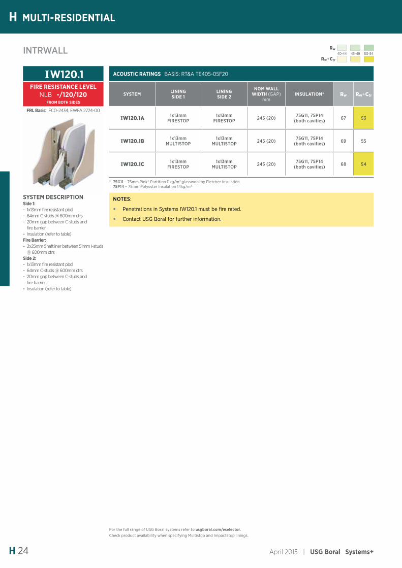
ACOUSTIC RATINGS BASIS: RT&A TE405-05F20
SYSTEM LINING SIDE 1
LINING SIDE 2
NOM WALL WIDTH (GAP)
mmINSULATION* Rw Rw+Ctr
IW120.1A 1x13mm FIRESTOP
1x13mm FIRESTOP 245 (20) 75G11, 75P14
(both cavities) 67 53
IW120.1B 1x13mm MULTISTOP
1x13mm MULTISTOP 245 (20) 75G11, 75P14
(both cavities) 69 55
IW120.1C 1x13mm FIRESTOP
1x13mm MULTISTOP 245 (20) 75G11, 75P14
(both cavities) 68 54
SYSTEM DESCRIPTIONSide 1: - 1x13mm fire resistant pbd - 64mm C-studs @ 600mm ctrs - 20mm gap between C-studs and fire barrier
- Insulation (refer to table)Fire Barrier: - 2x25mm Shaftliner between 51mm I-studs @ 600mm ctrs
Side 2: - 1x13mm fire resistant pbd - 64mm C-studs @ 600mm ctrs - 20mm gap between C-studs and fire barrier
- Insulation (refer to table).
IW120.1FIRE RESISTANCE LEVEL
NLB -/120/120FROM BOTH SIDES
* 75G11 – 75mm Pink® Partition 11kg/m3 glasswool by Fletcher Insulation. 75P14 – 75mm Polyester Insulation 14kg/m3
FRL Basis: FCO-2434, EWFA 2724-00
INTRWALL
NOTES:
• Penetrations in Systems IW120.1 must be fire rated.
• Contact USG Boral for further information.
For the full range of USG Boral systems refer to usgboral.com/eselector.Check product availability when specifying Multistop and Impactstop linings.
![September 2015 Generic Seismic Design - USG Boral · SEISMIC DESIGN STATEMENT Jacobs (formerly Sinclair Knight Merz [SKM]) has provided USG Boral with structural design services in](https://img.pdfslide.net/doc/110x75/5e6da852d29167699605df08/september-2015-generic-seismic-design-usg-boral-seismic-design-statement-jacobs.jpg)