Embed Size (px)
Citation preview

LBT90-SR Rev. A
T90-II HydroSeeder ®Parts and Operator’s Manual
Model SR Serial No. _____________
9281 LeSaint Drive • Fairfield, Ohio 45014Phone (513) 874-2818 • Fax (513) 874-2914
Sales: 1-800-543-7166
ActivateYour WarrantyBy Registering
TODAY!!!

NOTES
II
ACTIVATE YOUR FINN EQUIPMENT WARRANTY
IMPORTANT INFORMATION ON ACTIVATING YOUR FINN EQUIPMENT WARRANTY!!!
IT IS IMPERATIVE THAT YOU, THE PURCHASER, COMPLETE THE FOLLOWING STEP IN ORDER TO ACTIVATE THE FINN CORPORATION LIMITED WARRANTY.
COMPLETE THE “EQUIPMENT REGISTRATION” FORM ONTHE NEXT PAGE AND MAIL TO THE FINN CORPORATION.
IF FINN CORPORATION DOES NOT HAVE YOUR COMPLETED REGISTRATIONFORM ON FILE, YOUR WARRANTY CLAIM WILL BE DENIED.
Once your Finn equipment has been registered, your Finn Limited Warranty willbe activated per the warranty statement on the other side of this notice.
<<What should you do if you need repairs or parts under Warranty?>>
1. NOTIFY FINN CORPORATION OF THE FAILURE OF MATERIAL OR WORKMANSHIP
1-800-543-7166 Extension (246)[email protected]
2. AFTER YOU OR YOUR SERVICE DEALER NOTIFY FINN, FINN WILL:
VERIFY THAT WE HAVE YOUR “REGISTRATION” ON FILE
VERIFY THAT THE WARRANTY PERIOD IS IN EFFECT
VERIFY THAT THE RELATED PART(s) ARE INCLUDED IN THE SCOPE OF WARRANTY (PENDING FINN’S INSPECTION OF DEFECTIVE PARTS)
SEND YOU REPLACEMENT PART(S) AND A “WARRANTY INFORMATION PACKET"
REQUEST YOU FOLLOW ALL INSTRUCTIONS AS NOTED IN THE “PACKET”
▪ FilloutthePartsTag.(Completely)▪ AttachthePartsTagtothedefectivepart(s).▪ Returnthepart(s)andthecompletedWarrantyClaimFormtoFinn Corporationusingthereturnshippinglabel.(Within 2 weeks)
▪ TapetheOrangeidentifiersheet,markedwiththeW/RMA#onthe outsideoftheboxyouareshippingthedefectivepart(s)toFinnin.
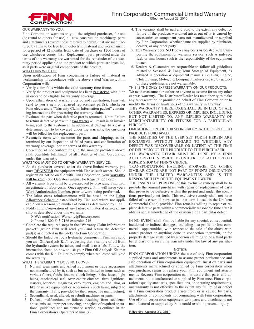
Finn Corporation Commercial Limited WarrantyEffective August 23, 2010
OUR WARRANTY TO YOU:Finn Corporation warrants to you, the original purchaser, for use (or rental to others for use) all new construction machinery, parts and attachments (except those referred to herein) that are manufac-tured by Finn to be free from defects in material and workmanship for a period of 12 months from date of purchase or 1200 hours of use, whichever comes first. Replacement parts provided under the terms of this warranty are warranted for the remainder of the war-ranty period applicable to the product to which parts are installed, as if parts were original components of the product.WHAT FINN WILL DO:Upon notification of Finn concerning a failure of material or workmanship in accordance with the above stated Warranty, Finn Corporation will:• Verify claim falls within the valid warranty time frame.• Verify the product and equipment has been registered with Finn
in order to be eligible for warranty coverage.• Upon affirmation of warranty period and registration, Finn will
send to you a new or repaired replacement part(s), whichever Finn elects and a “Warranty Claim Information packet” contain-ing instructions for processing the warranty claim.
• Evaluate the part when defective part is returned. Note: Failure to return defective part within two weeks will result in an invoice being sent to the customer. In addition, if damage to a part is determined not to be covered under the warranty, the customer will be billed for the replacement part.
• Reconcile costs with customer for parts and shipping, as de-termined by our inspection of failed parts, and confirmation of warranty coverage, per the terms of this warranty.
• Correction of nonconformities, in the manner provided above, shall constitute fulfillment of all liabilities of Finn Corporation under this warranty.
WHAT YOU MUST DO TO OBTAIN WARRANTY SERVICE:• As the purchaser covered under the above limited warranty you
must REGISTER the equipment with Finn as such owner. Should registration not be on file with Finn Corporation, your warranty will be void. (See Operators manual for Registration Form)
• All warranty labor must be pre-approved by providing Finn with an estimate of labor costs. Once approved, Finn will issue you a Work Authorization Number, prior to work being performed.
• The labor costs reimbursement will be based on the Labor Allowance Schedule established by Finn and where not appli-cable, on a reasonable number of hours as determined by Finn.
• Notify Finn Corporation of any failure of material or workman-ship as described under this warranty.Web notification: [email protected] 1-800-543-7166 extension 246
• Complete the required steps in the “Warranty Claim Information packet” (which Finn will send you) and return the defective part(s) as directed in the packet to Finn Corporation.
• Should the failed part be a hydraulic component, Finn may send you an “Oil Analysis Kit”, requesting that a sample of oil from the hydraulic system be taken, and mail it to a lab. Follow the instruction sheet, on how to use your Finn Oil Analysis Kit that comes with the Kit. Failure to comply when requested will void the warranty.
WHAT THE WARRANTY DOES NOT COVER: 1. Normal wear parts and Allied Equipment or trade accessories
not manufactured by it, such as but not limited to items such as various filters, fluids, brakes, clutch linings, belts, hoses, light bulbs, mechanical seal, over center clutches, tires, ignitions, starters, batteries, magnetos, carburetors, engines and labor, or like or unlike equipment or accessories. (Such being subject to the warranty, if any, provided by their respective manufacture).
2. Secondhand, used, altered, or rebuilt machines or parts. 3. Defects, malfunctions or failures resulting from accidents,
abuse, misuse, improper servicing, or neglect of required opera-tional guidelines and maintenance service, as outlined in the Finn Corporation’s Operators Manual(s).
4. The warranty shall be null and void to the extent any defect or failure of the products warranted arises out of or is caused by accessories or component parts not manufactured or supplied by Finn Corporation, whether same are supplied by purchaser, dealers, or any other party.
5. This Warranty does NOT cover any costs associated with trans-porting the equipment for warranty service, such as mileage, fuel, or man hours; such is the responsibility of the equipment owner.
6. Dealers & Customers are responsible to follow all guidelines related to Seasonal & Long Term Storage of Equipment, as advised in operation & equipment manuals. i.e. Finn, Engine, Clutch, Pump, Motor, etc. Equipment failures caused by neglect of these guidelines are not warrantable.
THIS IS THE ONLY EXPRESS WARRANTY ON OUR PRODUCTS:We neither assume nor authorize anyone to assume for us any other express warranty. The Distributor/Dealer has no authority to make any representation or promise on behalf of Finn Corporation or to modify the terms or limitations of this warranty in any way.THIS WARRANTY THEREFORE SHALL BE IN LIEU OF ALL OTHER WARRANTIES, EXPRESS OR IMPLIED, INCLUDING, BUT NOT LIMITED TO, ANY IMPLIED WARRANTY OF MERCHANTABILITY OR FITNESS FOR A PARTICULAR PURPOSE.LIMITATIONS ON OUR RESPONSIBILITY WITH RESPECT TO PRODUCTS PURCHASED:THE REMEDIES OF THE USER SET FORTH HEREIN ARE EXCLUSIVE, WITHOUT REGARD TO WHETHER ANY DEFECT WAS DISCOVERABLE OR LATENT AT THE TIME OF DELIVERY OF THE PRODUCT TO THE PURCHASER.ALL WARRANTY REPAIR MUST BE DONE BY A FINN AUTHORIZED SERVICE PROVIDER OR AUTHORIZED REPAIR SHOP OF FINN’S CHOICE.TRANSPORTATION, HAULING, STORAGE, OR OTHER SIMILAR COSTS ARE NOT PART OF FINN’S OBLIGATION UNDER THE LIMITED WARRANTIES AND IS THE RESPONSIBILITY OF THE EQUIPMENT OWNER.THE ESSENTIAL PURPOSE of this exclusive remedy shall be to provide the original purchaser with repair or replacement of parts that prove to be defective within the period and under the condi-tions previously set forth. This exclusive remedy shall not have failed of its essential purpose (as that term is used in the Uniform Commercial Code) provided Finn remains willing to repair or re-place defective parts within a commercially reasonable time after it obtains actual knowledge of the existence of a particular defect.
IN NO EVENT shall Finn be liable for any special, consequential, incidental or indirect damages, including lost profits or lost com-mercial opportunities, with respect to the sale of the above war-ranted product or anything done in connection therewith, or for property damage sustained by a person claiming to be a third party beneficiary of a surviving warranty under the law of any jurisdic-tion.
NOTICE:FINN CORPORATION URGES the use of only Finn corporation supplied parts and attachments to assure proper performance and safe operation of Finn corporation equipment. Insist on parts and attachments manufactured or supplied by Finn corporation when you purchase, repair or replace your Finn equipment and attach-ments. Because Finn corporation cannot assure that parts and at-tachments not manufactured or supplied by Finn meet Finn corpo-ration's quality standards, specifications, or operating requirements, our warranty is not effective to the extent any failure of or defect in a Finn corporation product arises from or is caused by parts, attachments or components not originating with Finn corporation. Use of Finn corporation equipment with parts and attachments not manufactured or supplied by Finn could result in personal injury.
Effective August 23, 2010

INDEX
Safety First . . . . . . . . . . . . . . . . . . . . . . . . . . . . . . . . . . . . . . . . . . . . . . . . . 1
Safety Summary Section . . . . . . . . . . . . . . . . . . . . . . . . . . . . . . . . . . . . 2-5
Definition of Hydroseeding. . . . . . . . . . . . . . . . . . . . . . . . . . . . . . . . . . . . . 6
The Finn HydroSeeder® & How It Works . . . . . . . . . . . . . . . . . . . . . . . . . 6
Mounting The HydroSeeder® . . . . . . . . . . . . . . . . . . . . . . . . . . . . . . . . 6-7
Attachments . . . . . . . . . . . . . . . . . . . . . . . . . . . . . . . . . . . . . . . . . . . . . . 7-8
Pre-Start Check . . . . . . . . . . . . . . . . . . . . . . . . . . . . . . . . . . . . . . . . . . . . . 8
Equipment Check. . . . . . . . . . . . . . . . . . . . . . . . . . . . . . . . . . . . . . . . . . 8-9
Two Valve Operation . . . . . . . . . . . . . . . . . . . . . . . . . . . . . . . . . . . . . .10-11
Starting Procedure . . . . . . . . . . . . . . . . . . . . . . . . . . . . . . . . . . . . . . . . . . 12
Area Coverage - Material Capacity . . . . . . . . . . . . . . . . . . . . . . . . . . 12-13
Tank Capacity Chart. . . . . . . . . . . . . . . . . . . . . . . . . . . . . . . . . . . . . . . . . 14
Loading. . . . . . . . . . . . . . . . . . . . . . . . . . . . . . . . . . . . . . . . . . . . . . . . 14-15
Prior to Application . . . . . . . . . . . . . . . . . . . . . . . . . . . . . . . . . . . . . . . . . . 16
Discharge Nozzle Selection . . . . . . . . . . . . . . . . . . . . . . . . . . . . . . . . . . . 16
Application of Slurry . . . . . . . . . . . . . . . . . . . . . . . . . . . . . . . . . . . . . . 16-18
I.General Application Techniques . . . . . . . . . . . . . . . . . . . . . . . . . 16-17
II. Discharge Through the Boom. . . . . . . . . . . . . . . . . . . . . . . . . . . . . 17
III.Procedures When Using Hoses . . . . . . . . . . . . . . . . . . . . . . . . 17-18
Reloading Procedure . . . . . . . . . . . . . . . . . . . . . . . . . . . . . . . . . . . . . . . . 18
Liming With The HydroSeeder® . . . . . . . . . . . . . . . . . . . . . . . . . . . . 18-19
Cleaning and Maintenance . . . . . . . . . . . . . . . . . . . . . . . . . . . . . . . . 20-21
After First 4-8 Hours of Operation . . . . . . . . . . . . . . . . . . . . . . . . . . . 20
Daily . . . . . . . . . . . . . . . . . . . . . . . . . . . . . . . . . . . . . . . . . . . . . . . . . . 20
Weekly or Every 40 Hours of Operation. . . . . . . . . . . . . . . . . . . . 20-21
Seasonal & Winter Storage Maintenance. . . . . . . . . . . . . . . . . . . . . . 21
Hydraulic System . . . . . . . . . . . . . . . . . . . . . . . . . . . . . . . . . . . . . . . . . . . 21
Lubrication & Fluids Chart . . . . . . . . . . . . . . . . . . . . . . . . . . . . . . . . . 22-23
Continued . . .
HydroSeeder® is a registered trademark of the Finn Corporation
INDEX Continued . . .
Clump Maintenance . . . . . . . . . . . . . . . . . . . . . . . . . . . . . . . . . . . . . . 24-25
Pump Maintenance . . . . . . . . . . . . . . . . . . . . . . . . . . . . . . . . . . . . . . 26-27
Clutch Maintenance . . . . . . . . . . . . . . . . . . . . . . . . . . . . . . . . . . . . . . 27-29
Trouble Shooting Your HydroSeeder®. . . . . . . . . . . . . . . . . . . . . . . . 29-33
T90 Skid-Mount/Trailer HydroSeeder® Technical Specifications . . . 34-35
Notes . . . . . . . . . . . . . . . . . . . . . . . . . . . . . . . . . . . . . . . . . . . . . . . . . . . . 36
PARTS SECTION . . . . . . . . . . . . . . . . . . . . . . . . . . . . . . . . . . . . . . . 37-69
T90 Trailer Pictorial Reference . . . . . . . . . . . . . . . . . . . . . . . . . . . . . . . . 38
T90 Skid Pictorial Reference . . . . . . . . . . . . . . . . . . . . . . . . . . . . . . . . . . 39
Trailer . . . . . . . . . . . . . . . . . . . . . . . . . . . . . . . . . . . . . . . . . . . . . . . . . 40-41
Skid . . . . . . . . . . . . . . . . . . . . . . . . . . . . . . . . . . . . . . . . . . . . . . . . . . 42-43
Operator's Platform . . . . . . . . . . . . . . . . . . . . . . . . . . . . . . . . . . . . . . 44-45
Wheel and Hub Assembly . . . . . . . . . . . . . . . . . . . . . . . . . . . . . . . . . 46-47
Agitator Assembly . . . . . . . . . . . . . . . . . . . . . . . . . . . . . . . . . . . . . . . 48-49
Hydraulic Agitator Drive . . . . . . . . . . . . . . . . . . . . . . . . . . . . . . . . . . . . . . 50
Trailer Wiring . . . . . . . . . . . . . . . . . . . . . . . . . . . . . . . . . . . . . . . . . . . . . . 51
Hydraulic System . . . . . . . . . . . . . . . . . . . . . . . . . . . . . . . . . . . . . . . . 52-53
Hose Reel Assembly (Option) . . . . . . . . . . . . . . . . . . . . . . . . . . . . . . 54-55
Hydraulic System w/ Hose Reel. . . . . . . . . . . . . . . . . . . . . . . . . . . . . 56-57
Discharge Boom Assembly . . . . . . . . . . . . . . . . . . . . . . . . . . . . . . . . 58-59
Control Box Wiring . . . . . . . . . . . . . . . . . . . . . . . . . . . . . . . . . . . . . . . 60-61
Piping . . . . . . . . . . . . . . . . . . . . . . . . . . . . . . . . . . . . . . . . . . . . . . . . . 62-63
Clutch/Pump Assembly . . . . . . . . . . . . . . . . . . . . . . . . . . . . . . . . . . . 64-65
Engine & Radiator . . . . . . . . . . . . . . . . . . . . . . . . . . . . . . . . . . . . . . . 66-67
Engine Wiring. . . . . . . . . . . . . . . . . . . . . . . . . . . . . . . . . . . . . . . . . . . . . . 68
Hose Reel Nozzles/Remote Valve/Tool Box . . . . . . . . . . . . . . . . . . . . . . 69
Decals . . . . . . . . . . . . . . . . . . . . . . . . . . . . . . . . . . . . . . . . . . . . . . . . 70-71
1
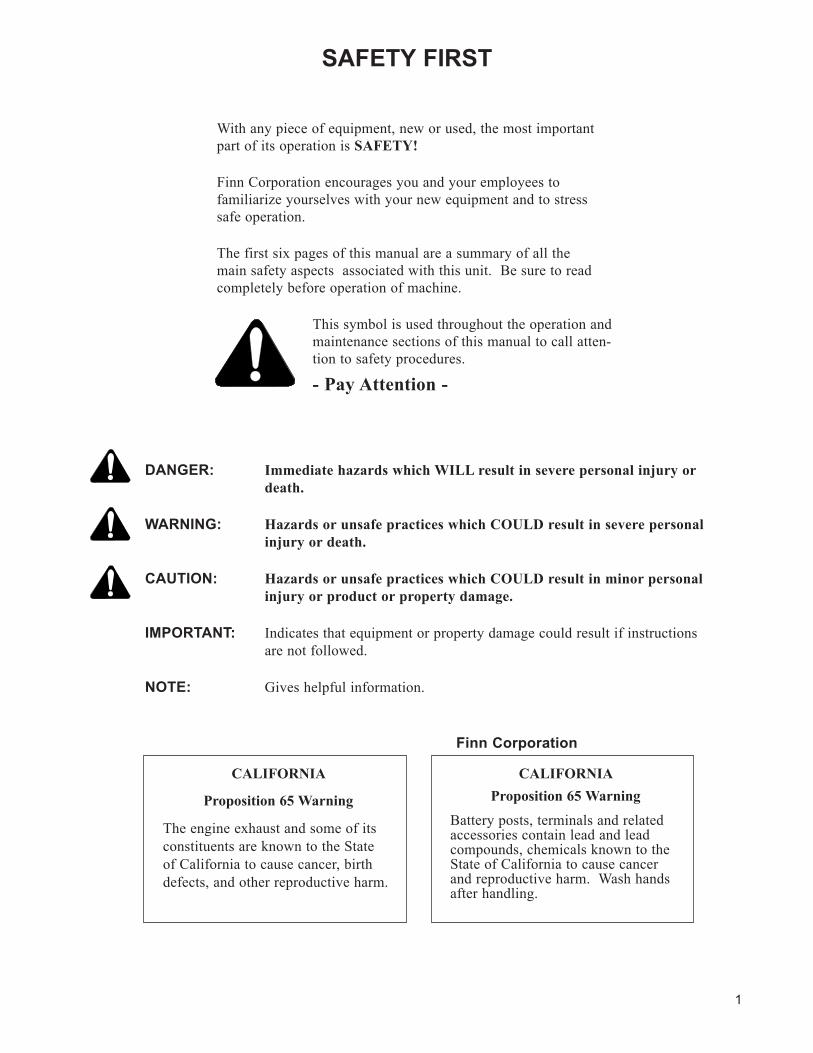
SAFETY FIRST
With any piece of equipment, new or used, the most important part of its operation is SAFETY!
Finn Corporation encourages you and your employees to familiarize yourselves with your new equipment and to stress safe operation.
The first six pages of this manual are a summary of all the main safety aspects associated with this unit. Be sure to read completely before operation of machine.
This symbol is used throughout the operation and maintenance sections of this manual to call atten-tion to safety procedures.
- Pay Attention -
DANGER: Immediate hazards which WILL result in severe personal injury or death.
WARNING: Hazards or unsafe practices which COULD result in severe personal injury or death.
CAUTION: Hazards or unsafe practices which COULD result in minor personal injury or product or property damage.
IMPORTANT: Indicates that equipment or property damage could result if instructions are not followed.
NOTE: Gives helpful information.
Finn Corporation
CALIFORNIA
Proposition 65 Warning
The engine exhaust and some of its constituents are known to the State of California to cause cancer, birth defects, and other reproductive harm.
CALIFORNIAProposition 65 Warning
Battery posts, terminals and related accessories contain lead and lead compounds, chemicals known to the State of California to cause cancer and reproductive harm. Wash hands after handling.
2
HYDROSEEDER® SAFETY SUMMARY SECTIONIt is important that all operators of this machine are familiar with all of the safety aspects mentioned below and have read the entire Operator’s Manual before operating the machine. Always keep a copy of this manual with the machine. It is the responsibility of the operator of the machine to fully understand this safety sheet. Remember that YOU are the key to safety. Good safety practices protect not only you but also the people work-ing with and around you. Keep in mind that this safety sheet is written for this type of machine only. Practice all other usual and customary safe working precautions; and above all, remember that safety is up to you.
The FINN HydroSeeder® is designed to mix and apply water, seed, fertilizer, agricultural lime and hydraulic mulch to the prepared seedbed. The resultant slurry from mixing one or more of the above materials may react causing harmful or deadly gasses within the tank. Heat, evaporation or extended emptying period can/will accelerate the formation of these gasses. Please contact your supplier(s) of these slurry components regarding their potential reactivity.
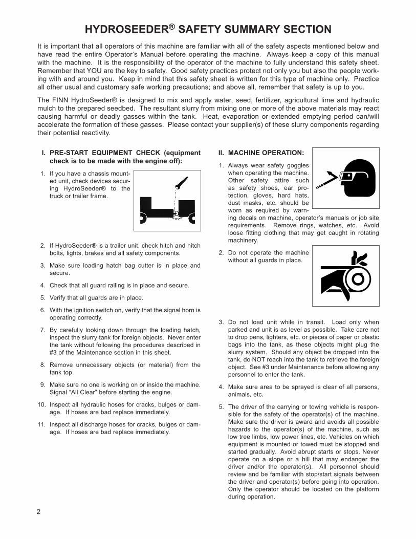
I.PRE-START EQUIPMENT CHECK (equipmentcheckistobemadewiththeengineoff):
1. If you have a chassis mount-ed unit, check devices secur-ing HydroSeeder® to the truck or trailer frame.
2. If HydroSeeder® is a trailer unit, check hitch and hitch bolts, lights, brakes and all safety components.
3. Make sure loading hatch bag cutter is in place and secure.
4. Check that all guard railing is in place and secure.
5. Verify that all guards are in place.
6. With the ignition switch on, verify that the signal horn is operating correctly.
7. By carefully looking down through the loading hatch, inspect the slurry tank for foreign objects. Never enter the tank without following the procedures described in #3 of the Maintenance section in this sheet.
8. Remove unnecessary objects (or material) from the tank top.
9. Make sure no one is working on or inside the machine. Signal “All Clear” before starting the engine.
10. Inspect all hydraulic hoses for cracks, bulges or dam-age. If hoses are bad replace immediately.
11. Inspect all discharge hoses for cracks, bulges or dam-age. If hoses are bad replace immediately.
II. MACHINE OPERATION:
1. Always wear safety goggles when operating the machine. Other safety attire such as safety shoes, ear pro-tection, gloves, hard hats, dust masks, etc. should be worn as required by warn-ing decals on machine, operator’s manuals or job site requirements. Remove rings, watches, etc. Avoid loose fitting clothing that may get caught in rotating machinery.
2. Do not operate the machine without all guards in place.
3. Do not load unit while in transit. Load only when parked and unit is as level as possible. Take care not to drop pens, lighters, etc. or pieces of paper or plastic bags into the tank, as these objects might plug the slurry system. Should any object be dropped into the tank, do NOT reach into the tank to retrieve the foreign object. See #3 under Maintenance before allowing any personnel to enter the tank.
4. Make sure area to be sprayed is clear of all persons, animals, etc.
5. The driver of the carrying or towing vehicle is respon-sible for the safety of the operator(s) of the machine. Make sure the driver is aware and avoids all possible hazards to the operator(s) of the machine, such as low tree limbs, low power lines, etc. Vehicles on which equipment is mounted or towed must be stopped and started gradually. Avoid abrupt starts or stops. Never operate on a slope or a hill that may endanger the driver and/or the operator(s). All personnel should review and be familiar with stop/start signals between the driver and operator(s) before going into operation. Only the operator should be located on the platform during operation.
3
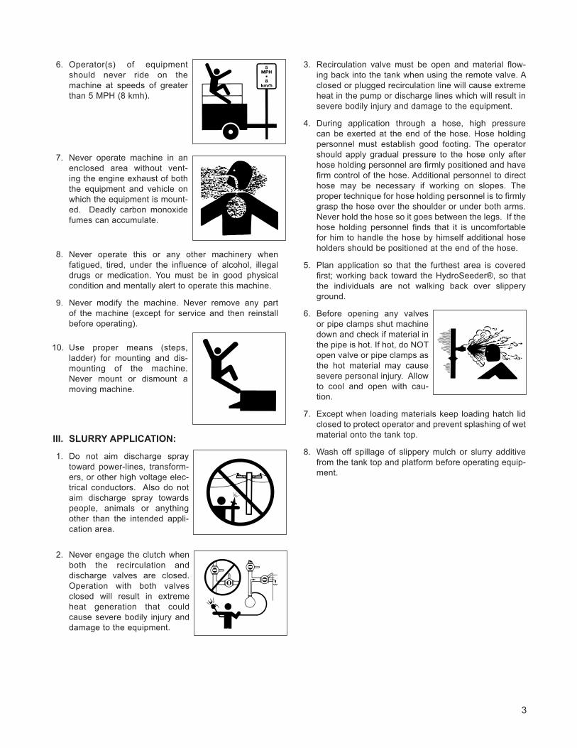
6. Operator(s) of equipment should never ride on the machine at speeds of greater than 5 MPH (8 kmh).
7. Never operate machine in an enclosed area without vent-ing the engine exhaust of both the equipment and vehicle on which the equipment is mount-ed. Deadly carbon monoxide fumes can accumulate.
8. Never operate this or any other machinery when fatigued, tired, under the influence of alcohol, illegal drugs or medication. You must be in good physical condition and mentally alert to operate this machine.
9. Never modify the machine. Never remove any part of the machine (except for service and then reinstall before operating).
10. Use proper means (steps, ladder) for mounting and dis-mounting of the machine. Never mount or dismount a moving machine.
III. SLURRY APPLICATION:
1. Do not aim discharge spray toward power-lines, transform-ers, or other high voltage elec-trical conductors. Also do not aim discharge spray towards people, animals or anything other than the intended appli-cation area.
2. Never engage the clutch when both the recirculation and discharge valves are closed. Operation with both valves closed will result in extreme heat generation that could cause severe bodily injury and damage to the equipment.
3. Recirculation valve must be open and material flow-ing back into the tank when using the remote valve. A closed or plugged recirculation line will cause extreme heat in the pump or discharge lines which will result in severe bodily injury and damage to the equipment.
4. During application through a hose, high pressure can be exerted at the end of the hose. Hose holding personnel must establish good footing. The operator should apply gradual pressure to the hose only after hose holding personnel are firmly positioned and have firm control of the hose. Additional personnel to direct hose may be necessary if working on slopes. The proper technique for hose holding personnel is to firmly grasp the hose over the shoulder or under both arms. Never hold the hose so it goes between the legs. If the hose holding personnel finds that it is uncomfortable for him to handle the hose by himself additional hose holders should be positioned at the end of the hose.
5. Plan application so that the furthest area is covered first; working back toward the HydroSeeder®, so that the individuals are not walking back over slippery ground.
6. Before opening any valves or pipe clamps shut machine down and check if material in the pipe is hot. If hot, do NOT open valve or pipe clamps as the hot material may cause severe personal injury. Allow to cool and open with cau-tion.
7. Except when loading materials keep loading hatch lid closed to protect operator and prevent splashing of wet material onto the tank top.
8. Wash off spillage of slippery mulch or slurry additive from the tank top and platform before operating equip-ment.
4
MAINTENANCE:
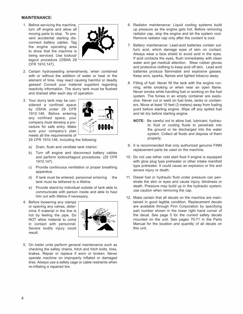
1. Before servicing the machine, turn off engine and allow all moving parts to stop. To pre-vent accidental starting dis-connect battery cables. Tag the engine operating area to show that the machine is being serviced. Use lockout/tagout procedure (OSHA 29 CFR 1910.147).
2. Certain hydroseeding amendments, when combined with or without the addition of water or heat or the element of time, may react causing harmful or deadly gasses! Consult your material suppliers regarding reactivity information. The slurry tank must be flushed and drained after each day of operation.
3. Your slurry tank may be con-sidered a confined space by OSHA under 29 CFR 1910.146. Before entering any confined space, your company must develop a pro-cedure for safe entry. Make sure your company’s plan meets all the requirements of 29 CFR 1910.146. Including the following:
a) Drain, flush and ventilate tank interior.b) Turn off engine and disconnect battery cables
and perform lockout/tagout procedures. (29 CFR 1910.147)
c) Provide continuous ventilation or proper breathing apparatus.
d) If tank must be entered, personnel entering the tank must be tethered to a lifeline.
e) Provide stand-by individual outside of tank able to communicate with person inside and able to haul him out with lifeline if necessary.
4. Before loosening any clamps or opening any valves, deter-mine if material in the line is hot by feeling the pipe. Do NOT allow material to come in contact with personnel. Severe bodily injury could result.
5. On trailer units perform general maintenance such as checking the safety chains, hitch and hitch bolts, tires, brakes. Repair or replace if worn or broken. Never operate machine on improperly inflated or damaged tires. Always use a safety cage or cable restraints when re-inflating a repaired tire.
6. Radiator maintenance: Liquid cooling systems build up pressure as the engine gets hot. Before removing radiator cap, stop the engine and let the system cool. Remove radiator cap only after the coolant is cool.
7. Battery maintenance: Lead-acid batteries contain sul-furic acid, which damage eyes of skin on contact. Always wear a face shield to avoid acid in the eyes. If acid contacts the eyes, flush immediately with clean water and get medical attention. Wear rubber gloves and protective clothing to keep acid off skin. Lead acid batteries produce flammable and explosive gasses. Keep arcs, sparks, flames and lighted tobacco away.
8. Filling of fuel: Never fill the tank with the engine run-ning, while smoking or when near an open flame. Never smoke while handling fuel or working on the fuel system. The fumes in an empty container are explo-sive. Never cut or weld on fuel lines, tanks or contain-ers. Move at least 10 feet (3 meters) away from fueling point before starting engine. Wipe off any spilled fuel and let dry before starting engine.
NOTE: Be careful not to allow fuel, lubricant, hydrau-lic fluid or cooling fluids to penetrate into the ground or be discharged into the water system. Collect all fluids and dispose of them properly.
9. It is recommended that only authorized genuine FINN replacement parts be used on the machine.
10. Do not use either cold start fluid if engine is equipped with glow plug type preheater or other intake manifold type preheater. It could cause an explosion or fire and severe injury or death.
11. Diesel fuel or hydraulic fluid under pressure can pen-etrate the skin or eyes and cause injury, blindness or death. Pressure may build up in the hydraulic system; use caution when removing the cap.
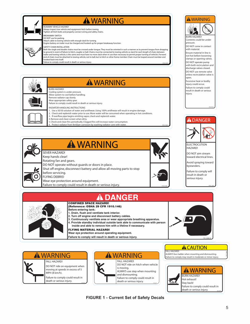
12. Make certain that all decals on the machine are main-tained in good legible condition. Replacement decals are available through Finn Corporation by specifying part number shown in the lower right hand corner of the decal. See page 5 for the current safety decals mounted on the unit. See pages 70-71 in the Parts Manual for the location and quantity of all decals on this unit.
5
FIGURE1-CurrentSetofSafetyDecals
6
OPERATION AND MAINTENANCE MANUAL FOR
THE FINN T90 HYDROSEEDER®
This manual gives you step-by-step instructions for the operation and maintenance of the Finn T90 HydroSeeder®. For best results and to insure longer life of the equipment, please follow the instructions carefully. For your safety read the entire manual before operating this unit.
DEFINITION OF HYDROSEEDING:Hydroseeding is the process whereby seed, fertilizer and/or lime and wood fiber mulch (using water as a carry-ing medium) are applied on the soil to establish vegetation.
THE FINN HYDROSEEDER® AND HOW IT WORKS:The Finn T90 HydroSeeder® will apply seed, fertilizer and/or lime, wood fiber mulch, or stabilizing materials in any prescribed or desired combination. The materials placed in the HydroSeeder® slurry-tank are mixed with water and kept in suspension by a dual agitation process, recirculation of slurry and mechanical agitation, thus forming a slurry that is pumped to the discharge assembly and directed onto the seed bed by the operator. This equipment is designed to accomplish hydroseeding in one easy operation with maximum efficiency.
MOUNTING THE HYDROSEEDER®:For speed and mobility of operation, the HydroSeeder® should be mounted on a truck or trailer, however, it is important to select a carrier with sufficient capacity to handle the added weight.
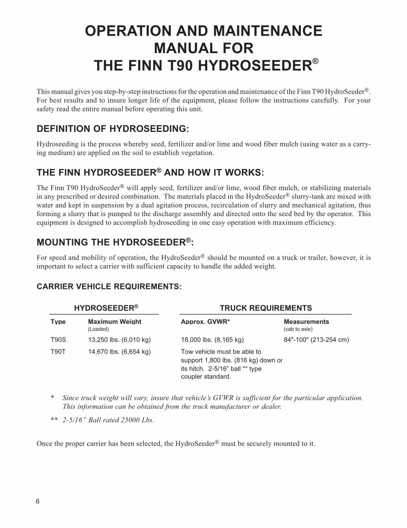
CARRIER VEHICLE REqUIREMENTS:
* Since truck weight will vary, insure that vehicle’s GVWR is sufficient for the particular application. This information can be obtained from the truck manufacturer or dealer.
** 2-5/16” Ball rated 25000 Lbs.
Once the proper carrier has been selected, the HydroSeeder® must be securely mounted to it.
Type Maximum Weight Approx. GVWR* Measurements(Loaded) (cab to axle)
T90S 13,250 lbs. (6,010 kg) 18,000 lbs. (8,165 kg) 84"-100" (213-254 cm)
T90T 14,670 lbs. (6,654 kg) Tow vehicle must be able to support 1,800 lbs. (816 kg) down on its hitch. 2-5/16” ball ** typecoupler standard.
HYDROSEEDER® TRUCK REQUIREMENTS
7
CAUTION: Your FINN HydroSeeder®shouldbemountedbyaqualifiedtruckbodyinstaller.
When mounting the T90 HydroSeeder® to the truck, any one of the following methods of mounting is accept-able:
A. Bolt the HydroSeeder® directly to the truck bed. Installer must insure that the bed as well as the bed to truck and HydroSeeder® to bed connections are adequate for the full load weights that are shown on page 6.
B. Mount the HydroSeeder® to the truck frame.
Note: The T90 HydroSeeder® has mounting legs that are 44” (111.76 cm) across and therefore require an adapter frame or a chassis bed of adequate strength to mount to the truck’s 34” (86.36 cm) wide rails.
IMPORTANT: Mounting the HydroSeeder® to the truck must allow for tire clearance as well as frame twist. Place hard wood spacers along the length of truck rails or use Finn spring mounting kit (#011562) or equivalent.
C. Place chains over the HydroSeeder® and around truck bed and secure with binders. Secure the HydroSeeder® with blocks tied to the truck bed.
IMPORTANT: When using a truck with a tilt bed be sure to chain the truck bed down to prevent the bed from being accidentally hoisted.
ATTACHMENTS:1. Extension hoses for reaching remote areas are available in 50 ft. (15m) lengths. All connections are
camlock quick operating fittings. The hose is connected to the end of the discharge boom in place of a nozzle. The nozzle is connected to the end of the hose and controlled by the person on the ground. The flow is controlled by a second person on the HydroSeeder®. This allows for a full pressure and volume operation.
2. For lower pressure applications, or for close up work, i.e. around buildings, the remote valve attachment can be used. The attachment includes semi-rigid hose with quick disconnect fittings along with a hand held valve which fits the end of the hose and accepts the standard nozzle assemblies. The hose is con-nected to the outlet on the discharge pipe above the pump. The machine is run at 1/2 to 3/4 throttle and material is applied where desired.
DANGER: Therecirculationvalvemustbeopenwhenusingaremotevalve.Ifvalveisnotopen,extremeheatwilloccurresultingindamageand/orbodilyinjury.
8
3. Hose Reel. The live hose reel will mount either on the HydroSeeder® or on the truck frame. The 200 foot (60.96 m)capacity electric rewind reel will wind up and store empty hose. It can be electrically connected to the HydroSeeder® battery.
4. Fill pumps with the capacity of 5,500 GPH (19,000 l/h) or 9,000 GPH (34,000 l/h) can either be car-ried on the truck or mounted on the HydroSeeder®.
5. Hardened pump parts. Pump casing, impeller, and suction cover treated with special material designed to resist wear.
6. Rear spray bar. The spray bar option is not designed for slurry application but for the dispersion of liquids for dust control, watering, feeding and washing applications. Rear spray bar can be arranged so that operation is remotely controlled from the truck cab.
PRE-START CHECK:Safety check to insure operator safety:
1. A. Skid Unit - Check condition of all mounting hardware securing HydroSeeder® to truck frame rails.
B. Trailer Unit - Inspect hitch, safety chains, lights, brakes and breakaway switch.
2. Make sure bag cutter is in place and secure.
3. Inspect that all railings are in place and secure.
4. Insure that all guards are in place.
EqUIPMENT CHECK:
CAUTION: Equipmentcheckismadewiththeengineoffandallrotatingpartsstopped.
1. Verify that the tool kit contains all the prescribed items (see tool kit list in parts section, page 67).
2. Inspect the “slurry-tank” for foreign objects. See numbers 2 and 3 in Maintenance Section (IV) of the Safety Summary Section, page 4.
3. Check fuel level.
4. Check the hydraulic oil level (see hydraulic system page 21 for oil specifications).
5. Check engine oil level. For oil type refer to the engine manual.
6. Check fluid level in radiator and overflow tank.
7. Inspect air cleaner for dust and dirt, clean if necessary.
8. Secure the drain plug on the outside-bottom of the slurry-tank.
9. Check to be certain pump drain plug is in place.
10. Verify that the suction line shut-off valve is completely open.
11. Engage and disengage clutch to determine if it “snaps” in and out.
9
12. Install discharge assembly (if stored in location other than standard operating position).A. Check and clean nozzle of any obstructions.B. Tighten the wing bolt at the opening around the top of discharge assembly and insure that
discharge assembly is secure.13. Check pump discharge and recirculation valve handles for free movement.
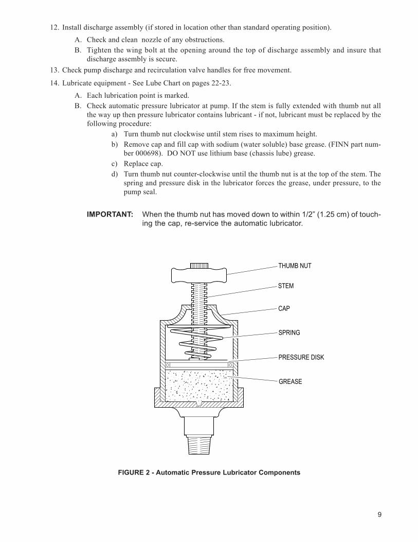
14. Lubricate equipment - See Lube Chart on pages 22-23.A. Each lubrication point is marked.B. Check automatic pressure lubricator at pump. If the stem is fully extended with thumb nut all
the way up then pressure lubricator contains lubricant - if not, lubricant must be replaced by the following procedure:
a) Turn thumb nut clockwise until stem rises to maximum height.b) Remove cap and fill cap with sodium (water soluble) base grease. (FINN part num-
ber 000698). DO NOT use lithium base (chassis lube) grease.c) Replace cap.d) Turn thumb nut counter-clockwise until the thumb nut is at the top of the stem. The
spring and pressure disk in the lubricator forces the grease, under pressure, to the pump seal.
IMPORTANT: When the thumb nut has moved down to within 1/2” (1.25 cm) of touch-ing the cap, re-service the automatic lubricator.
THUMB NUT
STEM
CAP
SPRING
PRESSURE DISK
GREASE
FIGURE2-AutomaticPressureLubricatorComponents
10
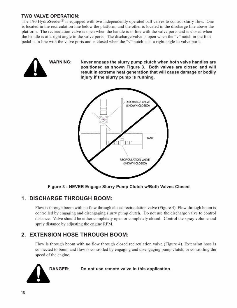
TWO VALVE OPERATION: The T90 HydroSeeder® is equipped with two independently operated ball valves to control slurry flow. One is located in the recirculation line below the platform, and the other is located in the discharge line above the platform. The recirculation valve is open when the handle is in line with the valve ports and is closed when the handle is at a right angle to the valve ports. The discharge valve is open when the “v” notch in the foot pedal is in line with the valve ports and is closed when the “v” notch is at a right angle to valve ports.
WARNING: NeverengagetheslurrypumpclutchwhenbothvalvehandlesarepositionedasshownFigure3. Bothvalvesareclosedandwillresultinextremeheatgenerationthatwillcausedamageorbodilyinjuryiftheslurrypumpisrunning.
Figure3-NEVEREngageSlurryPumpClutchw/BothValvesClosed
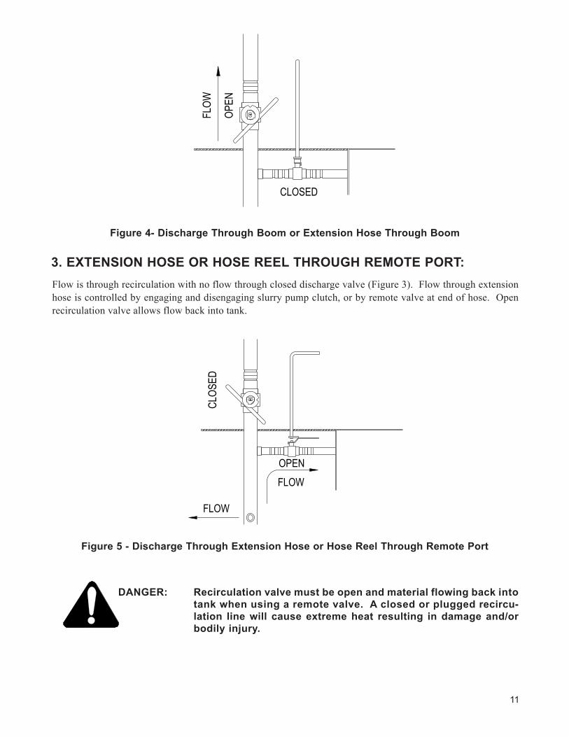
1. DISCHARGE THROUGH BOOM: Flow is through boom with no flow through closed recirculation valve (Figure 4). Flow through boom is
controlled by engaging and disengaging slurry pump clutch. Do not use the discharge valve to control distance. Valve should be either completely open or completely closed. Control the spray volume and spray distance by adjusting the engine RPM.
2. EXTENSION HOSE THROUGH BOOM: Flow is through boom with no flow through closed recirculation valve (Figure 4). Extension hose is
connected to boom and flow is controlled by engaging and disengaging pump clutch, or controlling the speed of the engine.
DANGER: Donotuseremotevalveinthisapplication.
11
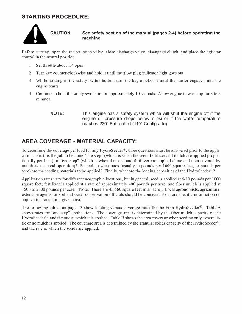
3. EXTENSION HOSE OR HOSE REEL THROUGH REMOTE PORT: Flow is through recirculation with no flow through closed discharge valve (Figure 3). Flow through extension hose is controlled by engaging and disengaging slurry pump clutch, or by remote valve at end of hose. Open recirculation valve allows flow back into tank.
DANGER: Recirculationvalvemustbeopenandmaterialflowingbackintotankwhenusingaremotevalve.Aclosedorpluggedrecircu-lation linewill causeextremeheat resulting indamageand/orbodilyinjury.
Figure4-DischargeThroughBoomorExtensionHoseThroughBoom
Figure5-DischargeThroughExtensionHoseorHoseReelThroughRemotePort
FLOW
OPEN
CLOSED
CLOS
ED
FLOW
FLOWOPEN
12
STARTING PROCEDURE:
CAUTION: Seesafetysectionofthemanual(pages2-4)beforeoperatingthemachine.
Before starting, open the recirculation valve, close discharge valve, disengage clutch, and place the agitator control in the neutral position.
1 Set throttle about 1/4 open.
2 Turn key counter-clockwise and hold it until the glow plug indicator light goes out.
3 While holding in the safety switch button, turn the key clockwise until the starter engages, and the engine starts.
4 Continue to hold the safety switch in for approximately 10 seconds. Allow engine to warm up for 3 to 5 minutes.
NOTE: This engine has a safety system which will shut the engine off if the engine oil pressure drops below 7 psi or if the water temperature reaches 230˚ Fahrenheit (110˚ Centigrade).
AREA COVERAGE - MATERIAL CAPACITY:To determine the coverage per load for any HydroSeeder®, three questions must be answered prior to the appli-cation. First, is the job to be done “one step” (which is when the seed, fertilizer and mulch are applied propor-tionally per load) or “two step” (which is when the seed and fertilizer are applied alone and then covered by mulch as a second operation)? Second, at what rates (usually in pounds per 1000 square feet, or pounds per acre) are the seeding materials to be applied? Finally, what are the loading capacities of the HydroSeeder®?
Application rates vary for different geographic locations, but in general, seed is applied at 6-10 pounds per 1000 square feet; fertilizer is applied at a rate of approximately 400 pounds per acre; and fiber mulch is applied at 1500 to 2000 pounds per acre. (Note: There are 43,560 square feet in an acre). Local agronomists, agricultural extension agents, or soil and water conservation officials should be contacted for more specific information on application rates for a given area.
The following tables on page 13 show loading versus coverage rates for the Finn HydroSeeder®. Table A shows rates for “one step” applications. The coverage area is determined by the fiber mulch capacity of the HydroSeeder®, and the rate at which it is applied. Table B shows the area coverage when seeding only, where lit-tle or no mulch is applied. The coverage area is determined by the granular solids capacity of the HydroSeeder®, and the rate at which the solids are applied.
13
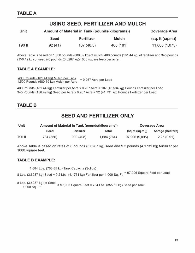
TABLE A
USINGSEED,FERTILIzERANDMULCH
Above Table is based on 1,500 pounds (680.39 kg) of mulch, 400 pounds (181.44 kg) of fertilizer and 345 pounds (156.49 kg) of seed ((8 pounds (3.6287 kg)/1000 square feet) per acre.
TABLE A EXAMPLE:
400 Pounds (181.44 kg) Mulch per Tank 1,500 Pounds (680.39 kg) Mulch per Acre = 0.267 Acre per Load
400 Pounds (181.44 kg) Fertilizer per Acre x 0.267 Acre = 107 (48.534 kg) Pounds Fertilizer per Load345 Pounds (156.49 kg) Seed per Acre x 0.267 Acre = 92 (41.731 kg) Pounds Fertilizer per Load
TABLE B
SEEDANDFERTILIzERONLy
Above Table is based on rates of 8 pounds (3.6287 kg) seed and 9.2 pounds (4.1731 kg) fertilizer per 1000 square feet.
TABLE B EXAMPLE:
1,684 Lbs. (763.85 kg) Tank Capacity (Solids)
8 Lbs. (3.6287 kg) Seed + 9.2 Lbs. (4.1731 kg) Fertilizer per 1,000 Sq. Ft. = 97,906 Square Feet per Load
8 Lbs. (3.6287 kg) of Seed 1,000 Sq. Ft. X 97,906 Square Feet = 784 Lbs. (355.62 kg) Seed per Tank
Unit Coverage Area
Seed Fertilizer Mulch (sq. ft.(sq.m.))
T90 II 92 (41) 107 (48.5) 400 (181) 11,600 (1,075)
Amount of Material in Tank (pounds(kilograms))
UnitSeed Fertilizer Total (sq. ft.(sq.m.)) Acrage (Hectare)
T90 II 784 (356) 900 (408) 1,684 (764) 97,906 (9,095) 2.25 (0.91)
Amount of Material in Tank (pounds(kilograms)) Coverage Area
14
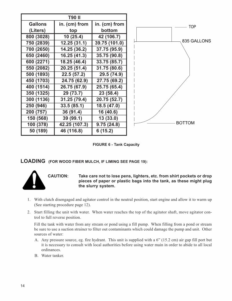
LOADING (FORWOODFIBERMULCH,IFLIMINGSEEPAGE19):
CAUTION: Takecarenottolosepens,lighters,etc.fromshirtpocketsordroppiecesofpaperorplasticbagsintothetank,asthesemightplugtheslurrysystem.
1. With clutch disengaged and agitator control in the neutral position, start engine and allow it to warm up (See starting procedure page 12).
2. Start filling the unit with water. When water reaches the top of the agitator shaft, move agitator con-trol to full reverse position.Fill the tank with water from any stream or pond using a fill pump. When filling from a pond or stream be sure to use a suction strainer to filter out contaminants which could damage the pump and unit. Other sources of water:A. Any pressure source, eg. fire hydrant. This unit is supplied with a 6” (15.2 cm) air gap fill port but
it is necessary to consult with local authorities before using water main in order to abide to all local ordinances.
B. Water tanker.
FIGURE6-TankCapacity
BOTTOM
TOP
835 GALLONS
T90 II Gallons in. (cm) from in. (cm) from(Liters) top bottom
800 (3028) 10 (25.4) 42 (106.7)750 (2839) 12.25 (31.1) 39.75 (101.0)700 (2650) 14.25 (36.2) 37.75 (95.9)650 (2460) 16.25 (41.3) 35.75 (90.8)600 (2271) 18.25 (46.4) 33.75 (85.7)550 (2082) 20.25 (51.4) 31.75 (80.6)500 (1893) 22.5 (57.2) 29.5 (74.9)450 (1703) 24.75 (62.9) 27.75 (69.2)400 (1514) 26.75 (67.9) 25.75 (65.4)350 (1325) 29 (73.7) 23 (58.4)300 (1136) 31.25 (79.4) 20.75 (52.7)250 (946) 33.5 (85.1) 18.5 (47.0)200 (757) 36 (91.4) 16 (40.6)150 (568) 39 (99.1) 13 (33.0)100 (378) 42.25 (107.3) 9.75 (24.8)50 (189) 46 (116.8) 6 (15.2)
15
3. Piping System Cleanout Procedure (Purging Line):A. Remove discharge nozzle and gasket from discharge boom.B. Aim discharge boom assembly into an open area away from any persons, obstructions or high
voltage power lines.C. Open discharge valve and close recirculation valve.D. Increase engine speed to approximately 1/2 to 3/4.E. Engage clutch with a firm snap. Do NOT slip clutch.F. When discharge stream is clear, open recirculation valve and close discharge valve. After
recirculation stream is clear disengage clutch.G. Replace gasket in discharge boom.
4. Continue filling tank with water.
5. Increase engine speed to full RPM.
6. Start loading dry material, loading the lightest material first. Agitator control should be in full reverse for mixing.
A. Seed - Cut the seed bag and dump contents into the slurry tank. (When using inoculant, add it in the tank along with the seed.) When using quick swelling seeds load them just prior to application.
B. Wood Fiber Mulch - Empty the entire bag in or cut bag and drop in the sections of fiber. The amount of mulch to be used should be loaded by the time the water level is at 3/4 full. If agitator stalls or a high pitch squeal comes from the hydraulic system, reverse agitation to forward for a moment to clear the obstruction, then return agitation to reverse.
CAUTION: Hydraulic system will overheat if agitator shaft is jammed forextended period. This will damage hydraulic oil and systemcomponents.
C. Fertilizer - Stand over hatch opening and drop the bag onto the bagcutter. Grasp both ends of the bag and dump material.
D. All other additives - Consult with manufacturer for proper loading technique.7. When all materials are loaded and in suspension, and the tank is full, move the agitator to neutral then
full speed forward to insure all material is mixed. It may be necessary to change the agitator direction more than once to insure a thorough mixture.
8. After material is thoroughly mixed, slow agitator in forward direction to 1/2 to 3/4 speed or enough to create movement in all of the corners of the tank. Do not over agitate the slurry. Always discharge the material with the agitator control in forward position.
9. Close the hatch lid on the slurry tank.
NOTE: The slurry should not be recirculated for more than 15 minutes prior to discharge to reduce wear and keep seed from swelling.
NOTE: If foaming occurs, reduce agitator speed.
16
PRIOR TO APPLICATION:1. Operator should familiarize self with area to be seeded and develop a plan to insure uniform applica-
tion.
2. Develop a plan for communication between operator and driver of the carrying or towing vehicle to sig-nal for start, stop, turn, etc. through the use of the signal horn.
3. Operator takes up position on the platform. From this point application will be controlled by the use of the clutch, valve, discharge assembly and throttle.
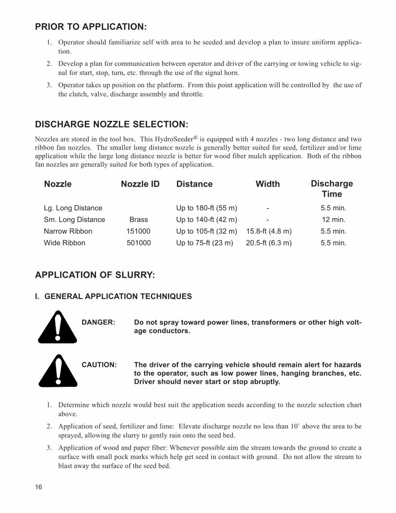
DISCHARGENOzzLESELECTION:Nozzles are stored in the tool box. This HydroSeeder® is equipped with 4 nozzles - two long distance and two ribbon fan nozzles. The smaller long distance nozzle is generally better suited for seed, fertilizer and/or lime application while the large long distance nozzle is better for wood fiber mulch application. Both of the ribbon fan nozzles are generally suited for both types of application.
APPLICATION OF SLURRY:
I. GENERAL APPLICATION TECHNIqUES
DANGER: Donotspraytowardpowerlines,transformersorotherhighvolt-ageconductors.
CAUTION: Thedriverofthecarryingvehicleshouldremainalertforhazardstotheoperator,suchaslowpowerlines,hangingbranches,etc.Drivershouldneverstartorstopabruptly.
1. Determine which nozzle would best suit the application needs according to the nozzle selection chart above.
2. Applicationofseed,fertilizerandlime:Elevatedischargenozzlenolessthan10˚abovetheareatobesprayed, allowing the slurry to gently rain onto the seed bed.
3. Application of wood and paper fiber: Whenever possible aim the stream towards the ground to create a surface with small pock marks which help get seed in contact with ground. Do not allow the stream to blast away the surface of the seed bed.
Nozzle Nozzle ID Distance Width
Lg. Long Distance Up to 180-ft (55 m) - 5.5 min.Sm. Long Distance Brass Up to 140-ft (42 m) - 12 min.Narrow Ribbon 151000 Up to 105-ft (32 m) 15.8-ft (4.8 m) 5.5 min.Wide Ribbon 501000 Up to 75-ft (23 m) 20.5-ft (6.3 m) 5.5 min.
DischargeTime
17
4. Generally the most remote area of the seed bed should be covered first. Distance is controlled by engine speed and nozzle selection. Do NOT partially close the valve to control the distance.
5. While moving along area to be seeded, the operator should move the nozzle back and forth in a slow, even arc.
6. If application is to be interrupted for a short period of time, leave the valves open and disengage the clutch. Re-engage the clutch to continue application.
7. It may be necessary to slow the agitator as the tank empties to reduce foaming.
II. DISCHARGE THROUGH THE BOOM:
1. Move the discharge valve handle to the open position, the recirculation valve handle to the closed posi-tion, and engage the clutch. At this time, should the operator want to stop spraying for a short period, disengage the clutch; then re-engage to continue spraying.
2. When the tank is empty, or when discontinuing discharge for an extended period of time, disengage the clutch, then immediately move the discharge valve to the closed position, and idle the engine. This will maintain moisture in the discharge piping and help prevent plugging. Move the agitator control to the neutral position.
III. PROCEDURES WHEN USING HOSES:
Always pump clear water through the hose before pumping mulch. If the inside hose liner is dry, it will dewater the mulch causing plugging.
A. PUMP TAKE OFF SYSTEM OR HOSE REEL WITH REMOTE VALVE :
1. Open recirculation valve and close discharge valve and close remote valve at the end of the hose.
2. Engage clutch. When stream is flowing freely through the recirculation line, open the pump take off valve.
CAUTION: Thehighpressureon thehosecanexert strong forces causinghoseoperator to losecontrolofhoseor footing. Thehosewillrequire additional holders on slopes. Open the pump take offvalveandtheremotevalveslowlyandonlyafterthehoseoperatorisfirmlypositionedandhasfirmcontrolofhose.
3. With the engine at 3/4 speed, open the remote valve at the end of the hose to discharge the load.
4. When finished spraying, close the remote valve, disengage the clutch, and stop the engine. If using fiber mulch, retain as much water as possible in the hose by elevating the ends or by coupling the ends together.
5. If another load is to be done, see reloading procedure on page 18. If finished for the day, follow the clean up procedure and flush out the hose.
DANGER: Therecirculationvalvemustbeopenwhenusingaremotevalve.Ifnotopen,extremeheatwhichwillcausedamageand/orbodilyinjurywilloccur.
18
B. EXTENSION HOSE SYSTEM - WITHOUT REMOTE VALVE:
1. Connect the extension hose into the end of the discharge boom.
2. A person controlling the end of the hose directs a second operator at the machine to control the clutch and adjust the engine speed.
CAUTION: Sincetheextensionhosewillbeseeingthefulloutputofthepumpwith the recirculation closed, the equipment operator and indi-vidualattheendofthehoseshouldexerciseextremecarewhenoperatingunitonhighpressure.Thehighpressureonthehosecan exert strong forces causing hose operator to lose controlof hose or footing. The hosewill require additional holders onslopes. Engagetheclutchonlyafter thehoseoperator is firmlypositionedandhasfirmcontrolofhose.
3. When hose operator is ready, signal the second operator to engage clutch and slowly increase the engine RPM until the desired discharge pressure is reached.
4. When finished spraying, disengage the clutch, stop the engine, and close the discharge valve. If using fiber mulch, retain as much water as possible in the hose by elevating the ends or by coupling the ends together.
5. If another load is to be done, see reloading procedure below. If finished for the day, follow clean up procedure and flush out the hose.
RELOADING PROCEDURE:1. Start at step 2 in loading procedure on page 14.
2. After last load of the day refer to the cleaning and maintenance section of the manual on pages 20-21.
LIMING WITH THE HYDROSEEDER®:In using large concentrations of granular solids through the HydroSeeder®, it is advisable to keep the slurry moving through the pump at all times. This keeps the solids from settling in the lines, and creating a stoppage. This unit was designed for the application of agricultural grade lime only.
PROCEDURE:1. With clutch disengaged and agitator control in neutral position, start engine and allow it to warm up (see
starting procedure on page 12)
2. Start filling the unit with water. When water reaches the top of the agitator shaft move agitator control to approximately 1/2 speed reverse.
3. Open both the recirculation and discharge valves.
4. Remove the discharge nozzle and gasket from the discharge boom.
5. Aim the discharge boom assembly into an open area away from any persons, obstructions or high voltage power lines.
6. Move the throttle to approximately 1/2 engine speed.
19
7. Engage the clutch, and move the throttle to full engine speed. A stream of water should be coming from the end of the recirculation pipe beside the hatch opening, as well as from the boom.
8. As soon as both streams are clear, close the discharge valve and make sure water is being recirculated back to the tank.
9. Decrease throttle to 3/4 speed. Increase agitator speed to full reverse. DO NOT DISENGAGE CLUTCH!
10. 20 lbs. (9.02 kg) of granular solids displaces approximately 1 gal. (3.8 l) of water. When filling the tank with water the volume of granular solids must be accounted for. For example; If using the maximum recommended capacity of 2,500 lbs (1,134 kg), 125 gal. (473.17) (2,500 / 20) would have to be subtract-ed from the total tank capacity 940 gal.(3,558.27 l) - 125 gal.(473.17 l) = 815 gal.(3,085.09 l) If 1,000 lbs. (453.59 kg) of solids were used, 50 gal. (189.27 l) (1,000 / 20) would have to be subtracted 940 gal. (3,558.27 l) - 50 gal. (189.27 l) = 890 gal. (3,369 l). 11. Fill the tank to the required capacity for the rate of granular solids to be applied.
12. Load the material (see “Loading” page 15, steps 5-8).
13. When ready to apply slurry, install gasket and nozzle into boom.
14. Move agitator control to 3/4 speed, forward.
15. With the clutch still engaged, open the discharge valve.
CAUTION: Todecreasepumpwearandincreasedischargedistance, itmaynowbedesirable toclose the recirculationvalve. However, therecirculationvalvemustbeopenBEFOREclosingthedischargevalveiftheapplicationofslurryistobeinterrupted.Extremeheat,whichwill causedamage and/or bodily injury,will occur if bothvalvesareclosed.
16. Apply the slurry (see “Application of Slurry” pages 16-17).
17. If another load is to be applied, start again at step “1”. If finished, follow the clean-up procedure.
20
CLEANING AND MAINTENANCE:
AFTER FIRST 4-8 HOURS OF OPERATION:
1. Check and adjust clutch - see page 27.
2. Re-torque wheel lugs - again after 7 days. (Trailer option only).
DAILY:
1. Cleaning the HydroSeeder®
A. Fill the slurry tank to the center of the agitator shaft.B. Move agitator lever to full speed to flush off inside of tank top and walls.C. Remove discharge nozzle and gasket from discharge boom.D. While pointing discharge toward an open area, move discharge valve handle to discharge posi-
tion and engage clutch. Allow to discharge until clear water is coming out.E. Move recirculation valve handle to recirculation and allow to run momentarily.F. Disengage clutch, idle the engine, move valve handle to discharge position, move agitator handle
to neutral and turn off the engine.G. Always remove the drain plug and allow the tank to drain.H. In freezing weather leave main tank drain plug out and remove pump drain plug. Move all slurry
valves to open position.I. Wash the outside of HydroSeeder®, including the radiator, to remove any corrosive materials.J. If using lime - the daily maintenance should be performed after every load.K. Cleaning out extension hoses.
2. Lubricating the HydroSeeder® (see lube chart pages 22-23).
IMPORTANT: Lubrication should be performed IMMEDIATELY AFTER cleaning of equipment. Engine not running.
A. Lubricate the agitator shaft bearings located on the outside front and rear of the slurry-tank.B. Service the automatic lubricator on the pump as needed (for service see page 9).C. Check the engine oil and replenish when necessary. Change oil and filter after first 50 hours
then 200 hours thereafter. Consult the engine operator’s manual for the correct grade of oil and the engine break-in procedure.
NOTE: Change engine oil and filter at least once anually even if the 200 hours have not been met.
D. Lubricate the swivel on the discharge assembly.
WEEKLY OR EVERY 40 HOURS OF OPERATING TIME:
1. Clean the air cleaner following the instructions in the engine operator’s manual.
2. Lubricate all the points on the HydroSeeder® as outlined in the daily maintenance section and, in addi-tion, lubricate the four grease fittings on the clutch/pump.
21
3. Check the level in the hydraulic oil reservoir - maintain level at sight gauge.
4. Check the clutch adjustment to insure that it “snaps” in and out of engagement. Adjust the clutch with the engine off.
5. Check the anti-freeze in the radiator.
6. Inspect the slurry-tank for build up of residue in the suction area and clear if necessary.
7. Check and clean engine radiator. Flush with clear low pressure water and blow dry with compressed air. Do NOT use high pressure water spray.
SEASONAL AND WINTER STORAGE MAINTENANCE:1. Drain the slurry tank of all water prior to storage and leave the drain plug disconnected.
2. Park unit in suitable location and chock wheels to prevent inadvertent movement.
3. If possible cover machine with tarp or park inside of an enclosure.
4. Store the HydroSeeder® with all slurry valve handles in the open position. To prevent damage from freezing, it is advisable to remove all slurry valves and store in a heated area.
5. Pour one quart of mineral oil or environmentally safe lubricant into the pump housing and spin pump by hand to prevent rust in the pump. Remove drain plug.
6. Chip and steel brush any interior rust spots in the slurry-tank and touch up with paint. See numbers 2 and 3 in Maintenance Section (IV) of the Safety Summary Section page 4.
7. Lubricate all fittings.
8. Check anti-freeze in radiator.
9. Lubricate equipment again just prior to starting operation after storage.
10. Change hydraulic oil and filter. (400 hours)
11. Disconnect battery cables. In cold weather, remove battery and store in safe warm place.
12. Add fuel stabilizer to fuel tank.
HYDRAULIC SYSTEM:The hydraulic system on your Finn HydroSeeder® is designed to give trouble free service, if maintained. The most important areas of maintenance are the hydraulic oil and filtration. The reservoir holds 19 gallons of ISO Grade 46 hydraulic oil. The hydraulic oil should be replaced per the lubrication schedule or if the oil becomes milky or it gives off a burnt odor. The hydraulic oil filter must be replaced on schedule with a 25 micron absolute filter - Finn part #021618. The hydraulic system relief is factory set at 2,100 psi.
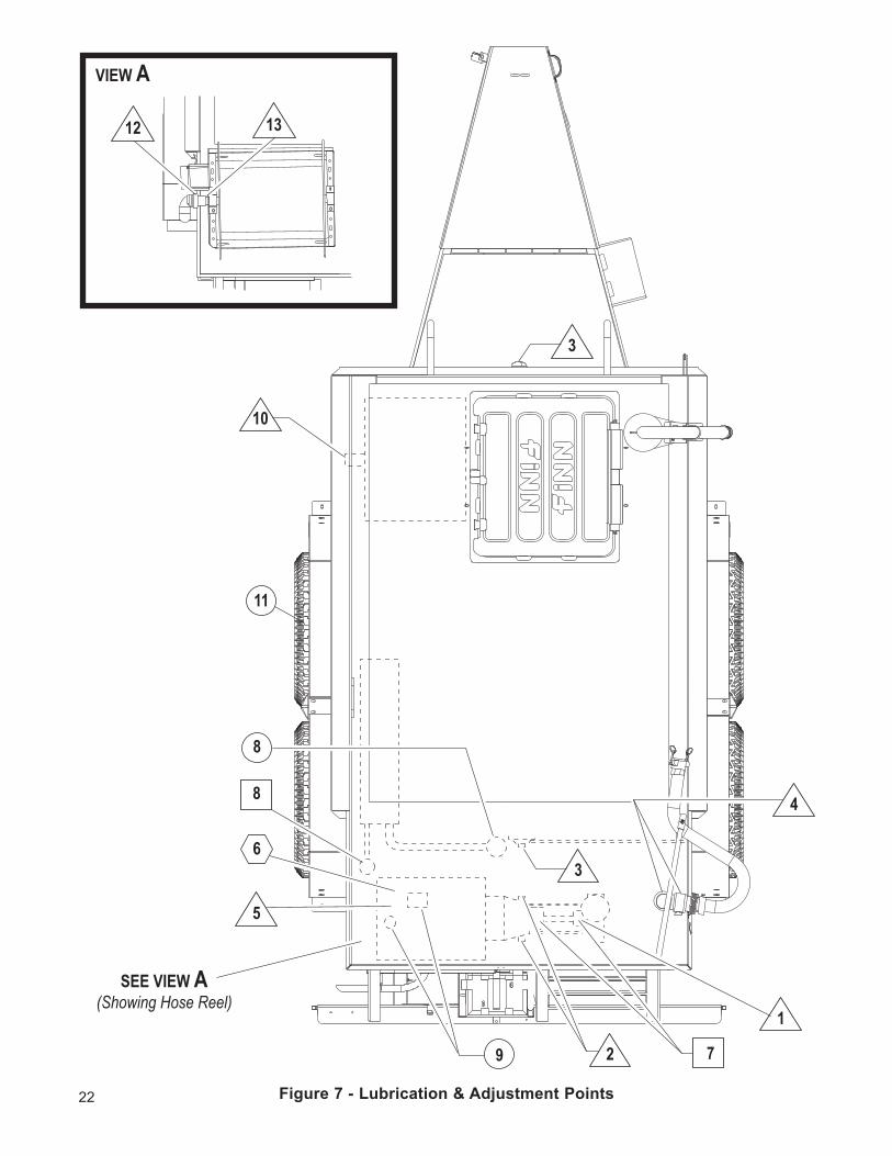
Figure7-Lubrication&AdjustmentPoints22
3
10
5
2
1
48
7
6
8
9
11
12 13
VIEW A
SEE VIEW A(Showing Hose Reel)
3
23
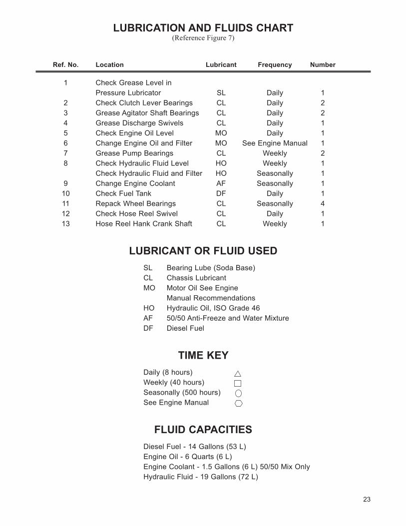
LUBRICATION AND FLUIDS CHART(Reference Figure 7)
Ref.No. Location Lubricant Frequency Number
1 Check Grease Level in Pressure Lubricator SL Daily 1 2 Check Clutch Lever Bearings CL Daily 2 3 Grease Agitator Shaft Bearings CL Daily 2 4 Grease Discharge Swivels CL Daily 1 5 Check Engine Oil Level MO Daily 1 6 Change Engine Oil and Filter MO See Engine Manual 1 7 Grease Pump Bearings CL Weekly 2 8 Check Hydraulic Fluid Level HO Weekly 1 Check Hydraulic Fluid and Filter HO Seasonally 1 9 Change Engine Coolant AF Seasonally 1 10 Check Fuel Tank DF Daily 1 11 Repack Wheel Bearings CL Seasonally 4 12 Check Hose Reel Swivel CL Daily 1 13 Hose Reel Hank Crank Shaft CL Weekly 1
LUBRICANT OR FLUID USEDSL Bearing Lube (Soda Base)CL Chassis LubricantMO Motor Oil See Engine Manual RecommendationsHO Hydraulic Oil, ISO Grade 46AF 50/50 Anti-Freeze and Water MixtureDF Diesel Fuel
TIME KEYDaily (8 hours)Weekly (40 hours)Seasonally (500 hours)See Engine Manual
FLUID CAPACITIESDiesel Fuel - 14 Gallons (53 L)Engine Oil - 6 Quarts (6 L)Engine Coolant - 1.5 Gallons (6 L) 50/50 Mix OnlyHydraulic Fluid - 19 Gallons (72 L)
24
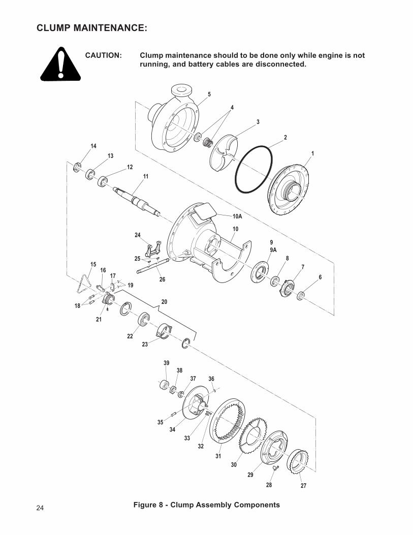
CLUMP MAINTENANCE:
CAUTION: Clumpmaintenanceshouldtobedoneonlywhileengineisnotrunning,andbatterycablesaredisconnected.
Figure8-ClumpAssemblyComponents
1
5
3
2
4
6
99A
78
10
11
14
12
13
19
20
24
25
26
22
1516
17
18
23
21
272829
3031
3233
3435
363738
39
10A
25
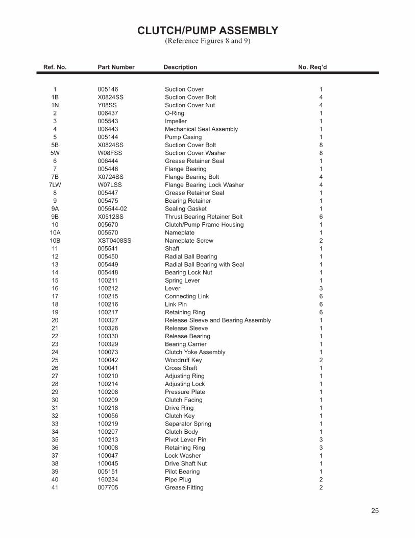
CLUTCH/PUMPASSEMBLy(Reference Figures 8 and 9)
Ref.No. PartNumber Description No.Req’d
1 005146 Suction Cover 1 1B X0824SS Suction Cover Bolt 4 1N Y08SS Suction Cover Nut 4 2 006437 O-Ring 1 3 005543 Impeller 1 4 006443 Mechanical Seal Assembly 1 5 005144 Pump Casing 1 5B X0824SS Suction Cover Bolt 8 5W W08FSS Suction Cover Washer 8 6 006444 Grease Retainer Seal 1 7 005446 Flange Bearing 1 7B X0724SS Flange Bearing Bolt 4 7LW W07LSS Flange Bearing Lock Washer 4 8 005447 Grease Retainer Seal 1 9 005475 Bearing Retainer 1 9A 005544-02 Sealing Gasket 1 9B X0512SS Thrust Bearing Retainer Bolt 6 10 005670 Clutch/Pump Frame Housing 1 10A 005570 Nameplate 1 10B XST0408SS Nameplate Screw 2 11 005541 Shaft 1 12 005450 Radial Ball Bearing 1 13 005449 Radial Ball Bearing with Seal 1 14 005448 Bearing Lock Nut 1 15 100211 Spring Lever 1 16 100212 Lever 3 17 100215 Connecting Link 6 18 100216 Link Pin 6 19 100217 Retaining Ring 6 20 100327 Release Sleeve and Bearing Assembly 1 21 100328 Release Sleeve 1 22 100330 Release Bearing 1 23 100329 Bearing Carrier 1 24 100073 Clutch Yoke Assembly 1 25 100042 Woodruff Key 2 26 100041 Cross Shaft 1 27 100210 Adjusting Ring 1 28 100214 Adjusting Lock 1 29 100208 Pressure Plate 1 30 100209 Clutch Facing 1 31 100218 Drive Ring 1 32 100056 Clutch Key 1 33 100219 Separator Spring 1 34 100207 Clutch Body 1 35 100213 Pivot Lever Pin 3 36 100008 Retaining Ring 3 37 100047 Lock Washer 1 38 100045 Drive Shaft Nut 1 39 005151 Pilot Bearing 1 40 160234 Pipe Plug 2 41 007705 Grease Fitting 2
26
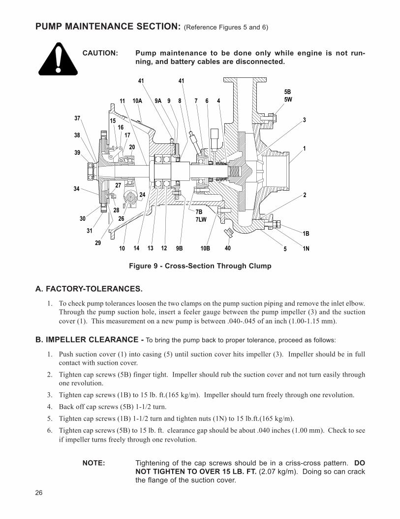
PUMP MAINTENANCE SECTION: (Reference Figures 5 and 6)
CAUTION: Pumpmaintenance to be done only while engine is not run-ning,andbatterycablesaredisconnected.
A. FACTORY-TOLERANCES.
1. To check pump tolerances loosen the two clamps on the pump suction piping and remove the inlet elbow. Through the pump suction hole, insert a feeler gauge between the pump impeller (3) and the suction cover (1). This measurement on a new pump is between .040-.045 of an inch (1.00-1.15 mm).
B. IMPELLER CLEARANCE - To bring the pump back to proper tolerance, proceed as follows:
1. Push suction cover (1) into casing (5) until suction cover hits impeller (3). Impeller should be in full contact with suction cover.
2. Tighten cap screws (5B) finger tight. Impeller should rub the suction cover and not turn easily through one revolution.
3. Tighten cap screws (1B) to 15 lb. ft.(165 kg/m). Impeller should turn freely through one revolution.4. Back off cap screws (5B) 1-1/2 turn.5. Tighten cap screws (1B) 1-1/2 turn and tighten nuts (1N) to 15 lb.ft.(165 kg/m).6. Tighten cap screws (5B) to 15 lb. ft. clearance gap should be about .040 inches (1.00 mm). Check to see
if impeller turns freely through one revolution.
NOTE: Tightening of the cap screws should be in a criss-cross pattern. DO NOT TIGHTEN TO OVER 15 LB. FT. (2.07 kg/m). Doing so can crack the flange of the suction cover.
1
2
3
1B
1N
5B5W
5
467
41
899A
41
10A11
20
1516
17
39
38
37
34
30
31
29
27
2826
10 14 13 12 9B 10B
7B7LW
40
24
Figure9-Cross-SectionThroughClump
27
C. CLEANING.
1. To clean pump impeller (3), loosen the two victaulic pipe clamps and remove the suction pipe assembly. The eye of the impeller can then be seen through the suction cover plate (1) and is readily accessible for cleaning.
2. To remove impeller, remove the eight bolts (5B) holding the suction cover (1) in place. Remove suction cover, being careful not to damage the O-Ring gasket (2).
3. Take the impeller wrench, which is stored in the toolbox, and position it so that the hole is aligned with anyoftheeighttappedholesinthefrontofthepumpcasing(5).The90˚legofthewrenchshouldfacein towards the impeller and be positioned between any two of the impeller fins. Bolt the wrench securely in place with one of the suction cover bolts (5B). Using a pipe wrench on the shaft (11), unscrew the impeller turning the shaft in a clockwise direction. Be careful not to unscrew the impeller too far before removing the puller wrench.
D.INSTALLINGNEWSEALASSEMBLy(#4) (Do not unwrap the new seal assembly until you are ready to install. All parts of the assembly are packed in sequence of installation.)
1. To replace the seal assembly (4), perform the above operations under cleaning and remove pump casing (5) by removing the three bolts (10B) holding the casing to the clutch housing (10).
2. After cleaning all parts including pump shaft, begin the reassembly of the pump. Install seal grease retainer (6) with the cavity portion of the seal facing outward. Rebolt the casing onto the clutch hous-ing using the three cap screw (10B). Using a light oil lubricant (3 in 1), install the ceramic seat with its neoprene holder into the seal recess making sure it is square with the shaft. Lubricate the inside of the bellows assembly with a light oil and check to be sure the steel ring is stuck (glued) to the end of the assembly. Slide the bellows assembly onto the shaft and push till the steel ring is against the ceramic seat.
3. Install the seal spring on the hub of the impeller. After coating the threads on the pump shaft with an anti-seize compound, install the impeller - seating it securely.
4. Utilizing the rubber O-Ring gasket (2) reinstall suction cover using the eight cover bolts (5B). At this time, check to see that the pump runs freely. If the impeller rubs the cover plate, you do not have the impeller tight on the shaft or the cover plate needs readjustment - see “impeller clearance”. Tighten these bolts uniformly using 15 ft. pounds (2.07 kg/m) on the torque wrench.
5. After reinstalling the suction pipe assembly, lubricate and tighten the victaulic clamps. Service the auto-matic lubricator.
CLUTCH MAINTENANCE SECTION: (REFERENCE FIGURES 8 AND 9)
CAUTION: Clutchmaintenance tobedoneonlywhile engine isnot run-ning,andbatterycablesaredisconnected.
A. ADJUSTMENT - If the clutch does not pull, overheats, or the clutch operating lever jumps out, the clutch must be adjusted. Proceed as follows:
1. Remove the hand hole nameplate (10A) in the housing (10) and rotate the clutch until the adjusting lock collar and lock screw (28) can be reached. Remove or disengage the adjusting lock (28) being careful not to drop it into the housing.
2. Turn the adjusting ring (27) counter clockwise to obtain recommended operating lever pressure.
28
HANDLE PRESSURE: Variation in handle length directly affects the pressure required at the handle for proper clutch adjust-
ment. See the table below to determine the correct handle pressure.
IMPORTANT: A new clutch generally requires several adjustments until the friction surfaces are worn in. Do not let a clutch slip as this will glaze the fric-tion plates and may ruin them.
B. LUBRICATION.1. Lubricant: Use any high grade, Lithium Base #2, short fiber grease having an operating temperature of
200˚F(93˚C),recommendedforrollerbearingsmaybeused.
IMPORTANT: Do not mix Sodium or Calcium base grease with Lithium grease.
2. Anti-Friction Bearings: Shaft bearings should be lubricated after each 50 hours of operation through fittings (41) with a short fiber, high grade, high temperature, Lithium Base #2 lubricant having an operatingtemperatureof200˚F(93˚C).Usethesamelubricanttooccasionallylubricatethetwofittings at the cross shaft (26).
3. Clutch Lever and Linkage: Levers and linkage should be lubricated with engine oil after every 500 hours of operation.
IMPORTANT: Lubricate sparingly to avoid oil on clutch facings.
C.REMOVALOFCLUTCH/PUMPFROMENGINE.1. Remove the clamps and piping from the suction and discharge side of the pump.2. Place a jack under the bell housing of the engine to support the rear of the engine after the clutch/
pump has been remvoed. 3. Engage the clutch handle, atop the operator’s platform, to hold clutch facings in place when removing
the clutch from the engine. Unbolt the rod which connects the clutch operating lever to the operator’s platform clutch handle
4. Attach a suitable lifting device to the clutch/pump frame housing (10). Remove the hex head cap screws that secure the clutch housing to the engine flywheel housing and the two bolts holding the housing to the HydroSeeder® frame.
IMPORTANT: Caution should be exercised when removing clutch/pump housing from the engine so that the facings and pilot bearing are not damaged.
5. Support the housing assembly on blocks with the output end of the shaft down.
6. Remove the hand hole nameplate (10A) from the housing for improved access to internal parts.
D. CLUTCH FACING PLATES (ITEM 30) REPLACEMENT: A common indication that the facings’ friction surface is worn out is that the adjusting ring cannot be turned any tighter. To replace the facing plates remove the clutch/pump from the engine as described above and proceed as follows:
Reference PressureHandle Length at Lever
7-1/2" 7-5/8" 110 to 130 Lbs
Clutch Size
29
1. Disengage the clutch operating lever and remove the old facing plates (30).2. Insert the new facing plates (three segments) in between the clutch body (34) and the pressure plate (29),
and center the facings as close as possible.3. Lock the clutch facings between the pressure plates as follows:
A. Remove the drive ring (31) from the engine flywheel so that it can be used to center the fac-ings.
B. With the clutch assembly resting on a workbench, turn the clutch adjusting ring COUNTER-CLOCKWISE until the pressure plate (29) almost contacts the clutch facing (30).
C. Place clutch driving ring over clutch facings with teeth in driving ring in mesh with teeth of clutch facings, and locate driving ring centrally relative to the pressure plate and clutch body.
NOTE: If driving ring is not properly located relative to the pressure plate and clutch body, the clutch cannot be assembled to the flywheel as the teeth of clutch facings will not enter the teeth of driving ring even though the clutch drive shaft enters the pilot bearing.
D. Engage the clutch by applying pressure on top of release sleeve and collar assembly (20) and lock clutch facings between the pressure plate and clutch body. If clutch facings are still free to move, disengage the clutch and turn adjusting ring COUNTER-CLOCKWISE just enough to lock the clutch facings in place when clutch is engaged.
NOTE: The clutch must now be engaged until the clutch assembly is attached to the engine.
4. Remove clutch driving ring (31) from the clutch facings and attach it to the flywheel with the specified bolts and lock washers.
5. Before re-installing clutch onto engine lubricate the release sleeve (21) through the grease fitting mount-ed on its side.
6. To re-install the clutch/pump assembly onto the engine, reverse the procedure outline under C. Removal of Clutch/Pump from engine on page 28.
7. When clutch/pump are re-installed check handle engage pressure and adjust if necessary.
TROUBLE SHOOTING YOUR HYDROSEEDER®:Because of the tremendous work load usually placed upon the HydroSeeder®, minor malfunctions will occur from time to time. If these are not remedied immediately, they could lead to poor performance and damage to the equipment. This section describes possible problems and the action to correct them.
1. Foam in the tank and air entrainment.
The mixture of dry materials with water will sometimes cause excessive foaming while others will cause air entrainment. This is noticed primarily in the erratic discharge and a drop in pressure and distance.
Some solutions are:A. As the slurry level drops in the tank, slow the agitator.B. Add 2 or 3 ounces (4 to 6 cl) of an antifoaming agent to the tank.C. If you can determine which additive is causing the air problem, either add it last or not at all -
unless it’s the water.D. Limit recirculation time as much as possible.
30
2. Plugging or clogging:
DANGER: Turnoffengineanddisconnectbatterycablesbeforeworkingonequipment.Seriousinjuryordeathcanresultfrommovingpartsorhighpressurespray.
Sometimes when a stoppage occurs, you will not be able to find anything in the line. When this happens, it means that the system became airbound instead of plugged. To remedy this, see “Foaming”. Plugging can occur in any one of four places; the valve and recirculation nozzle, the discharge nozzle, the pump area and the sump area. The plugging is caused by either foreign objects or dewatered fiber.
A. Obstruction in the discharge nozzle is determined by a change or stoppage of the spray pattern.a) Disengage clutch.b) Remove the nozzle.c) Clear the nozzle with the nozzle cleaning rod attached to the underside of the guard rail.
DANGER: Severeinjurycanresultfromopeningclampswhenpipingishot.Beforelooseninganyclamps,determineifthepipeishot. Ifso,letitcoolbeforeattemptingrepair.
B. If the recirculation system is not working:a) Disengage the clutch and shut down the engine.b) Remove the two clamps on each side of the recirculation valve.c) Slide the rubber seals back and remove the valve assembly.d) Check the valve assembly, the recirculation nozzle in the discharge pipe, and the recirculation
pipe going into the tank. Clear any obstructions.e) Replace the valve assembly and slide the seals back into place. Lubricate the outside of the
seals.f) Replace the clamps.
3. Obstruction in the pump, which can be determined by a drop in pressure. If the drop in pressure is accompanied by a frothy or whitish discharge stream, the blockage is in the suction line or sump area. To clear the pump:
A. Disengage the clutch and stop the engine.B. Loosen the suction pipe clamps. If there is material in the tank, shut off the suction line valveC. Remove the clamp closest to the pump.
NOTE: If no water comes out, it means the obstruction is in the sump area.
E. Reach into the pump and remove the obstruction. If it is jammed, the pump suction cover may have to be removed.
F. Reassemble removing pipe “plug” in process.G. Open suction line valve.
4. Obstruction in the sump area, which is located at the bottom of the tank on the inside where the suc-tion pipe is attached:
A. The easiest way to clear the sump is to back flush through the discharge plumbing with the water supply hose.
B. Another method is to remove the drain plug and run a long pole through the opening and into the sump area. Remove the obstruction and replace the drain cap.
C. Use a pipe or pole through the loading hatch opening to dislodge the obstruction.
31
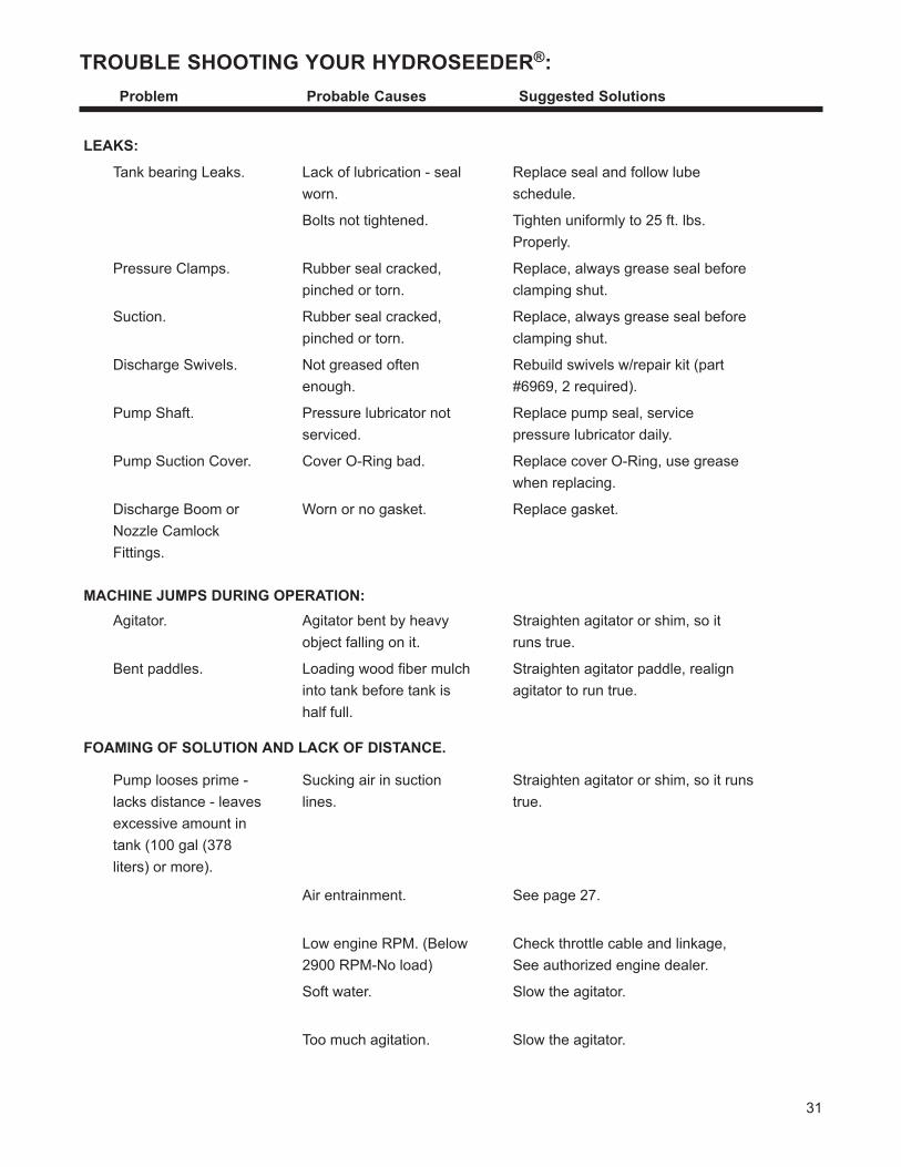
TROUBLE SHOOTING YOUR HYDROSEEDER®: Problem ProbableCauses SuggestedSolutions
LEAKS:
Tank bearing Leaks. Lack of lubrication - seal worn.
Replace seal and follow lube schedule.
Bolts not tightened. Tighten uniformly to 25 ft. lbs. Properly.
Pressure Clamps. Rubber seal cracked, pinched or torn.
Replace, always grease seal before clamping shut.
Suction. Rubber seal cracked, pinched or torn.
Replace, always grease seal before clamping shut.
Discharge Swivels. Not greased often enough.
Rebuild swivels w/repair kit (part #6969, 2 required).
Pump Shaft. Pressure lubricator not serviced.
Replace pump seal, service pressure lubricator daily.
Pump Suction Cover. Cover O-Ring bad. Replace cover O-Ring, use grease when replacing.
Discharge Boom or Nozzle Camlock Fittings.
Worn or no gasket. Replace gasket.
MACHINE JUMPS DURING OPERATION:Agitator. Agitator bent by heavy
object falling on it.Straighten agitator or shim, so it runs true.
Bent paddles. Loading wood fiber mulch into tank before tank is half full.
Straighten agitator paddle, realign agitator to run true.
FOAMING OF SOLUTION AND LACK OF DISTANCE.
Pump looses prime - lacks distance - leaves excessive amount in tank (100 gal (378 liters) or more).
Sucking air in suction lines.
Straighten agitator or shim, so it runs true.
Air entrainment. See page 27.
Low engine RPM. (Below 2900 RPM-No load)
Check throttle cable and linkage, See authorized engine dealer.
Soft water. Slow the agitator.
Too much agitation. Slow the agitator.
32
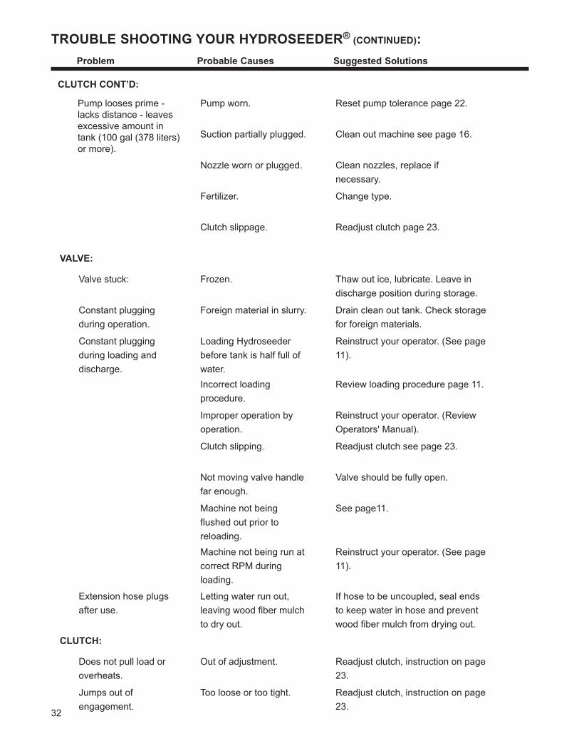
TROUBLE SHOOTING YOUR HYDROSEEDER® (CONTINUED): Problem ProbableCauses SuggestedSolutions
Pump worn. Reset pump tolerance page 22.
Suction partially plugged. Clean out machine see page 16.
Nozzle worn or plugged. Clean nozzles, replace if necessary.
Fertilizer. Change type.
Clutch slippage. Readjust clutch page 23.
VALVE:
Valve stuck: Frozen. Thaw out ice, lubricate. Leave in discharge position during storage.
Constant plugging during operation.
Foreign material in slurry. Drain clean out tank. Check storage for foreign materials.
Constant plugging during loading and discharge.
Loading Hydroseeder before tank is half full of water.
Reinstruct your operator. (See page 11).
Incorrect loading procedure.
Review loading procedure page 11.
Improper operation by operation.
Reinstruct your operator. (Review Operators' Manual).
Clutch slipping. Readjust clutch see page 23.
Not moving valve handle far enough.
Valve should be fully open.
Machine not being flushed out prior to reloading.
See page11.
Machine not being run at correct RPM during loading.
Reinstruct your operator. (See page 11).
Extension hose plugs after use.
Letting water run out, leaving wood fiber mulch to dry out.
If hose to be uncoupled, seal ends to keep water in hose and prevent wood fiber mulch from drying out.
CLUTCH:
Does not pull load or overheats.
Out of adjustment. Readjust clutch, instruction on page 23.
Jumps out of engagement.
Too loose or too tight. Readjust clutch, instruction on page 23.
CLUTCH CONT’D:
Pump looses prime -lacks distance - leavesexcessive amount intank (100 gal (378 liters)or more).
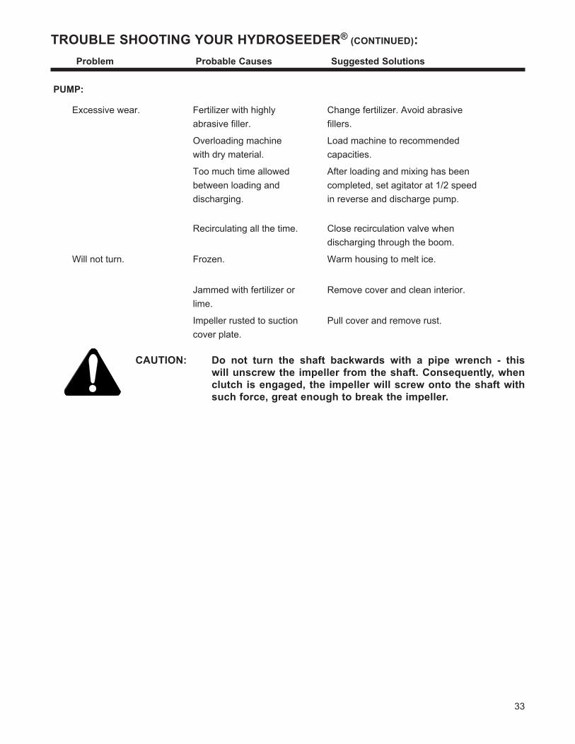
33
TROUBLE SHOOTING YOUR HYDROSEEDER® (CONTINUED): Problem ProbableCauses SuggestedSolutions
CAUTION: Do not turn the shaft backwards with a pipe wrench - thiswillunscrewtheimpellerfromtheshaft.Consequently,whenclutchisengaged,theimpellerwillscrewontotheshaftwithsuchforce,greatenoughtobreaktheimpeller.
PUMP:
Excessive wear. Fertilizer with highly abrasive filler.
Change fertilizer. Avoid abrasive fillers.
Overloading machine with dry material.
Load machine to recommended capacities.
Too much time allowed between loading and discharging.
After loading and mixing has been completed, set agitator at 1/2 speed in reverse and discharge pump.
Recirculating all the time. Close recirculation valve when discharging through the boom.
Will not turn. Frozen. Warm housing to melt ice.
Jammed with fertilizer or lime.
Remove cover and clean interior.
Impeller rusted to suction cover plate.
Pull cover and remove rust.
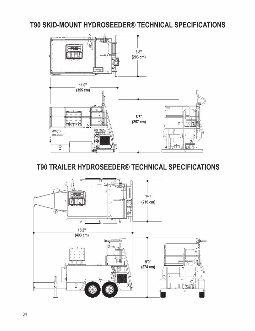
34
T90 SKID-MOUNT HYDROSEEDER® TECHNICAL SPECIFICATIONS
T90 TRAILER HYDROSEEDER® TECHNICAL SPECIFICATIONS
16′2″(493 cm)
7′1″(216 cm)
9′0″(274 cm)
11′0″(355 cm)
6′8″(203 cm)
8′5″(257 cm)
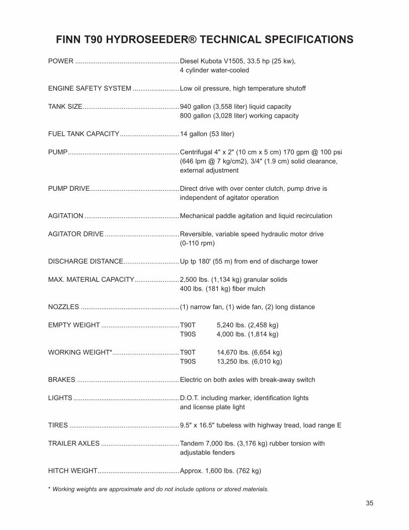
35
FINN T90 HYDROSEEDER® TECHNICAL SPECIFICATIONS
POWER ........................................................Diesel Kubota V1505, 33.5 hp (25 kw), 4 cylinder water-cooled
ENGINE SAFETY SYSTEM .........................Low oil pressure, high temperature shutoff
TANK SIZE ....................................................940 gallon (3,558 liter) liquid capacity 800 gallon (3,028 liter) working capacity
FUEL TANK CAPACITY ................................14 gallon (53 liter)
PUMP ............................................................Centrifugal 4" x 2" (10 cm x 5 cm) 170 gpm @ 100 psi (646 lpm @ 7 kg/cm2), 3/4" (1.9 cm) solid clearance, external adjustment
PUMP DRIVE ................................................Direct drive with over center clutch, pump drive is independent of agitator operation
AGITATION ...................................................Mechanical paddle agitation and liquid recirculation
AGITATOR DRIVE ........................................Reversible, variable speed hydraulic motor drive (0-110 rpm)
DISCHARGE DISTANCE ..............................Up tp 180' (55 m) from end of discharge tower
MAX. MATERIAL CAPACITY ........................2,500 lbs. (1,134 kg) granular solids 400 lbs. (181 kg) fiber mulch
NOZZLES ..................................................... (1) narrow fan, (1) wide fan, (2) long distance
EMPTY WEIGHT ..........................................T90T 5,240 lbs. (2,458 kg) T90S 4,000 lbs. (1,814 kg)
WORKING WEIGHT* ....................................T90T 14,670 lbs. (6,654 kg) T90S 13,250 lbs. (6,010 kg)
BRAKES .......................................................Electric on both axles with break-away switch
LIGHTS .........................................................D.O.T. including marker, identification lights and license plate light
TIRES ...........................................................9.5" x 16.5" tubeless with highway tread, load range E
TRAILER AXLES ..........................................Tandem 7,000 lbs. (3,176 kg) rubber torsion with adjustable fenders
HITCH WEIGHT ............................................Approx. 1,600 lbs. (762 kg)
* Working weights are approximate and do not include options or stored materials.

NOTES
36

37
T90HydroSeeder®
Parts ManualModel SR
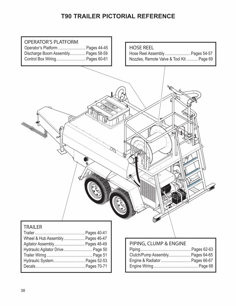
38
TRAILERTrailer ............................................... Pages 40-41Wheel & Hub Assembly.................... Pages 46-47Agitator Assembly............................. Pages 48-49Hydraulic Agitator Drive ........................... Page 50Trailer Wiring ........................................... Page 51Hydraulic System.............................. Pages 52-53Decals............................................... Pages 70-71
PIPING, CLUMP & ENGINEPiping................................................ Pages 62-63Clutch/Pump Assembly..................... Pages 64-65Engine & Radiator ............................ Pages 66-67Engine Wiring .......................................... Page 68
HOSE REELHose Reel Assembly ........................ Pages 54-57Nozzles, Remote Valve & Tool Kit ........... Page 69
OPERATOR’S PLATFORMOperator’s Platform .......................... Pages 44-45Discharge Boom Assembly............... Pages 58-59Control Box Wiring............................ Pages 60-61
T90 TRAILER PICTORIAL REFERENCE
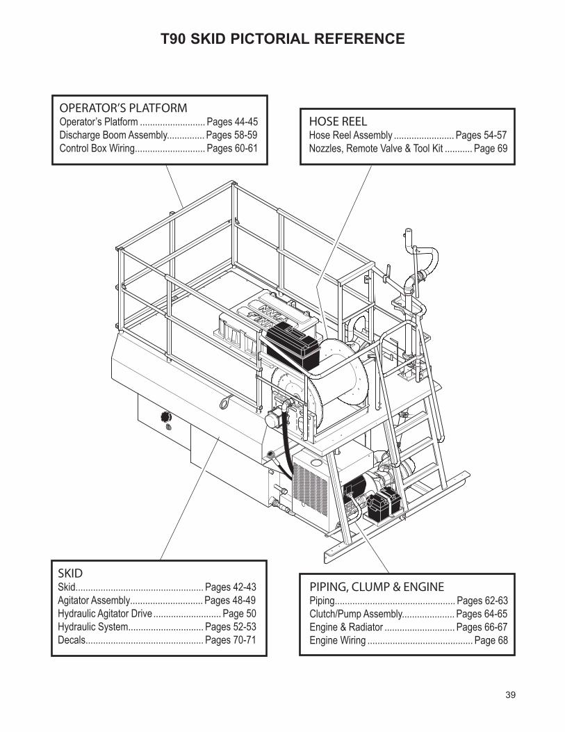
39
T90 SKID PICTORIAL REFERENCE
SKIDSkid................................................... Pages 42-43Agitator Assembly............................. Pages 48-49Hydraulic Agitator Drive ........................... Page 50Hydraulic System.............................. Pages 52-53Decals............................................... Pages 70-71
PIPING, CLUMP & ENGINEPiping................................................ Pages 62-63Clutch/Pump Assembly..................... Pages 64-65Engine & Radiator ............................ Pages 66-67Engine Wiring .......................................... Page 68
HOSE REELHose Reel Assembly ........................ Pages 54-57Nozzles, Remote Valve & Tool Kit ........... Page 69
OPERATOR’S PLATFORMOperator’s Platform .......................... Pages 44-45Discharge Boom Assembly............... Pages 58-59Control Box Wiring............................ Pages 60-61
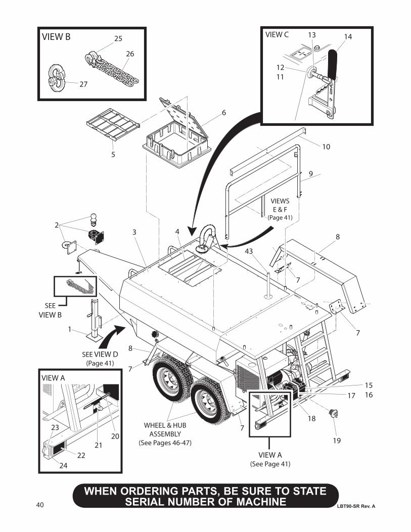
40
WHENORDERINGPARTS,BESURETOSTATESERIAL NUMBER OF MACHINE LBT90-SR Rev. A
VIEW A
VIEW B 25
26
27
2
1
3 48
7
WHEEL & HUBASSEMBLY
(See Pages 46-47)
8
7
151617
187
VIEW A(See Page 41)
6
5
SEEVIEW B
1211
13 14VIEW C
SEE VIEW D(Page 41)
9
192021
2224
23
10
VIEWSE & F
(Page 41)
7
43
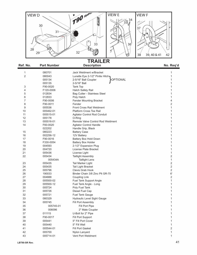
41
WHENORDERINGPARTS,BESURETOSTATESERIAL NUMBER OF MACHINELBT90-SR Rev. A
TRAILERRef.No. PartNumber Description No.Req’d
1 080701 Jack Weldment w/Bracket 1 2 080043 Lunette Eye 2-1/2" Pintle Hitch 1 005134 2-5/16" Ball Coupler 1 005135 2-5/16" Ball 1 3 F90-0020 Tank Top 1 4 F120-0006 Hatch Safety Rail 1 5 012834 Bag Cutter - Stainless Steel 1 6 012833 Poly Hatch 1 7 F90-0006 Fender Mounting Bracket 4 8 F90-0011 Fender 2 9 005536 Front Cross Rail Weldment 1 10 005462-01 Platform Cross Toe Rail 1 11 005515-01 Agitator Control Rod Conduit 1 12 005178 O-Ring 1 13 005516-01 Remote Valve Control Rod Weldment 1 14 F60-0020 Agitator Control Handle 1 022202 Handle Grip, Black 1 15 080223 Battery Case 1 16 002256-12 12V Battery 1 17 F90-0016 Battery Box Hold Down 1 18 F330-0054 Battery Box Holder 1 19 004593 2-1/2" Expansion Plug 1 20 004720 License Plate Bracket 1 21 005436 License Light 1 22 005434 Taillight Assembly 2 005434A Taillight Lens 1 23 005435 Tail Marker Light 2 24 005435 Tail Light Bracket 2 25 005796 Clevis Grab Hook 2 26 190033 Binder Chain 3/8 Zinc Plt GR-70 6' 27 004888 Coupling Link 2 28 005500-02 Fuel Tank Support Angle 1 29 005500-12 Fuel Tank Angle - Long 1 30 005724 Poly Fuel Tank 1 31 005726 Diesel Fuel Cap 1 32 005721 Fuel Tank Gauge 1 33 080329 Hydraulic Level Sight Gauge 1 34 005745 Fill Port Assembly 1 35 005745-01 Fill Port Pipe 1 36 006096 2" Male Coupler 1 37 011115 U-Bolt for 2" Pipe 1 38 F90-0017 Fill Port Support 1 39 005441 5" Fill Port Cover 1 40 005440 5" Fill Well 1 41 005544-01 Fill Port Gasket 2 42 005700 Nylon Lanyard 1 43 005714-01 Vent Port Weldment 1
}OPTIONAL
VIEW D
30
31
32
33
2829
VIEW E VIEW F
35
36
34
37
38 39, 40 & 41 42
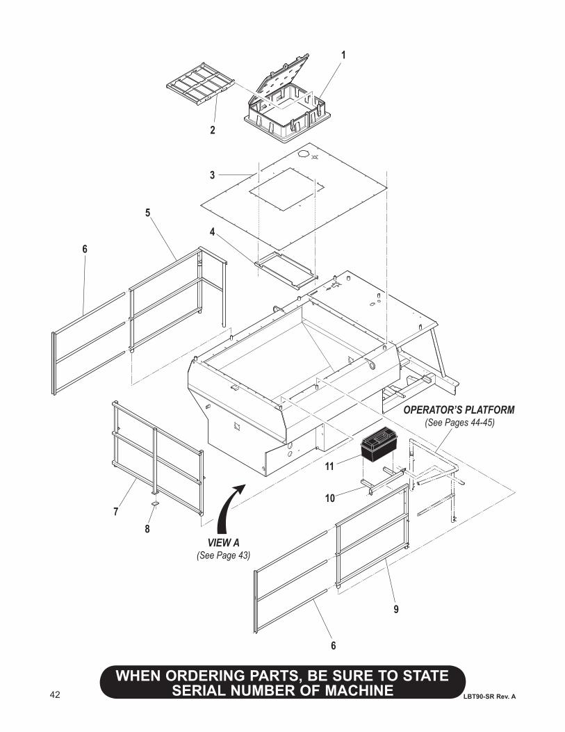
42
WHENORDERINGPARTS,BESURETOSTATESERIAL NUMBER OF MACHINE LBT90-SR Rev. A
1
2
3
45
6
7
9
6
10
11
OPERATOR’S PLATFORM(See Pages 44-45)
VIEW A(See Page 43)
8
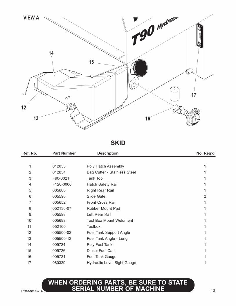
43
WHENORDERINGPARTS,BESURETOSTATESERIAL NUMBER OF MACHINELBT90-SR Rev. A
SKIDRef.No. PartNumber Description No.Req’d
1 012833 Poly Hatch Assembly 1 2 012834 Bag Cutter - Stainless Steel 1 3 F90-0021 Tank Top 1 4 F120-0006 Hatch Safety Rail 1 5 005600 Right Rear Rail 1 6 005596 Slide Gate 2 7 005652 Front Cross Rail 1 8 052136-07 Rubber Mount Pad 1 9 005598 Left Rear Rail 1 10 005698 Tool Box Mount Weldment 1 11 052160 Toolbox 1 12 005500-02 Fuel Tank Support Angle 1 13 005500-12 Fuel Tank Angle - Long 1 14 005724 Poly Fuel Tank 1 15 005726 Diesel Fuel Cap 1 16 005721 Fuel Tank Gauge 1 17 080329 Hydraulic Level Sight Gauge 1
VIEW A
1415
16
17
12
13
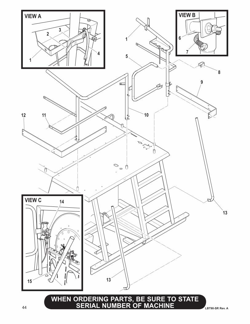
44
WHENORDERINGPARTS,BESURETOSTATESERIAL NUMBER OF MACHINE LBT90-SR Rev. A
VIEW A VIEW B
VIEW C
1
23
4
1
5
6
8
9
101112
13
13
14
15
7
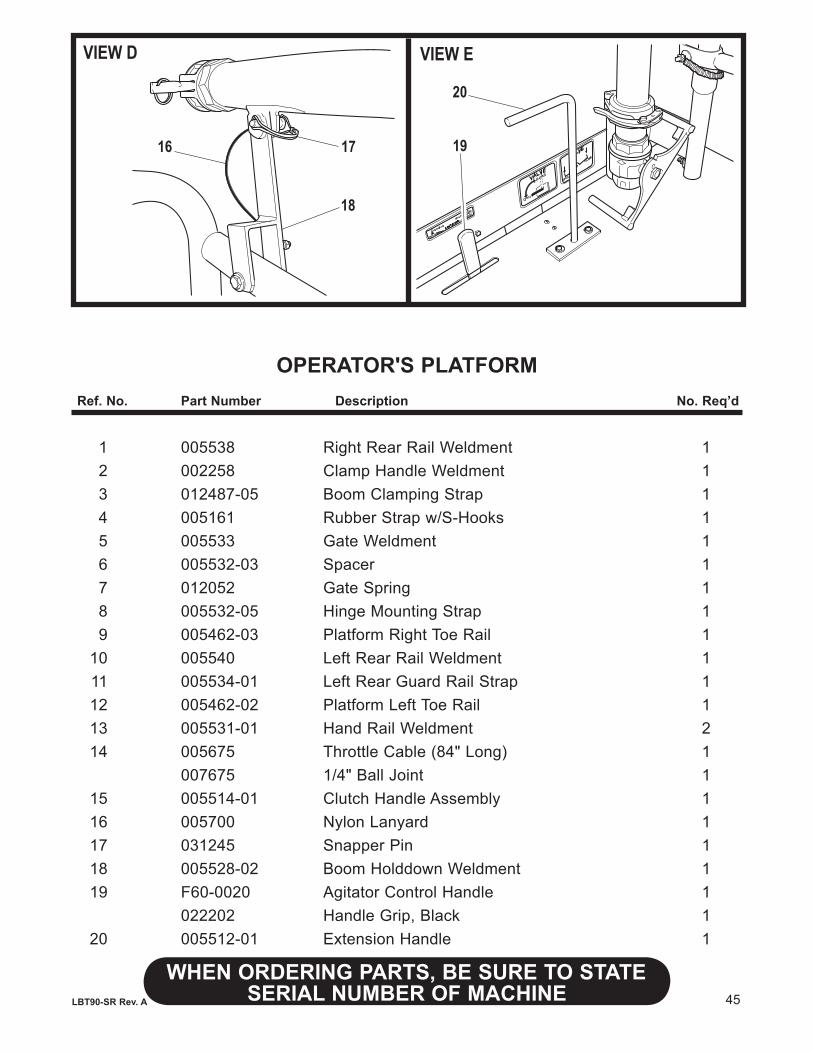
45
WHENORDERINGPARTS,BESURETOSTATESERIAL NUMBER OF MACHINELBT90-SR Rev. A
OPERATOR'S PLATFORMRef.No. PartNumber Description No.Req’d
1 005538 Right Rear Rail Weldment 1 2 002258 Clamp Handle Weldment 1 3 012487-05 Boom Clamping Strap 1 4 005161 Rubber Strap w/S-Hooks 1 5 005533 Gate Weldment 1 6 005532-03 Spacer 1 7 012052 Gate Spring 1 8 005532-05 Hinge Mounting Strap 1 9 005462-03 Platform Right Toe Rail 1 10 005540 Left Rear Rail Weldment 1 11 005534-01 Left Rear Guard Rail Strap 1 12 005462-02 Platform Left Toe Rail 1 13 005531-01 Hand Rail Weldment 2 14 005675 Throttle Cable (84" Long) 1 007675 1/4" Ball Joint 1 15 005514-01 Clutch Handle Assembly 1 16 005700 Nylon Lanyard 1 17 031245 Snapper Pin 1 18 005528-02 Boom Holddown Weldment 1 19 F60-0020 Agitator Control Handle 1 022202 Handle Grip, Black 1 20 005512-01 Extension Handle 1
VIEW D VIEW E
16 17
18
19
20
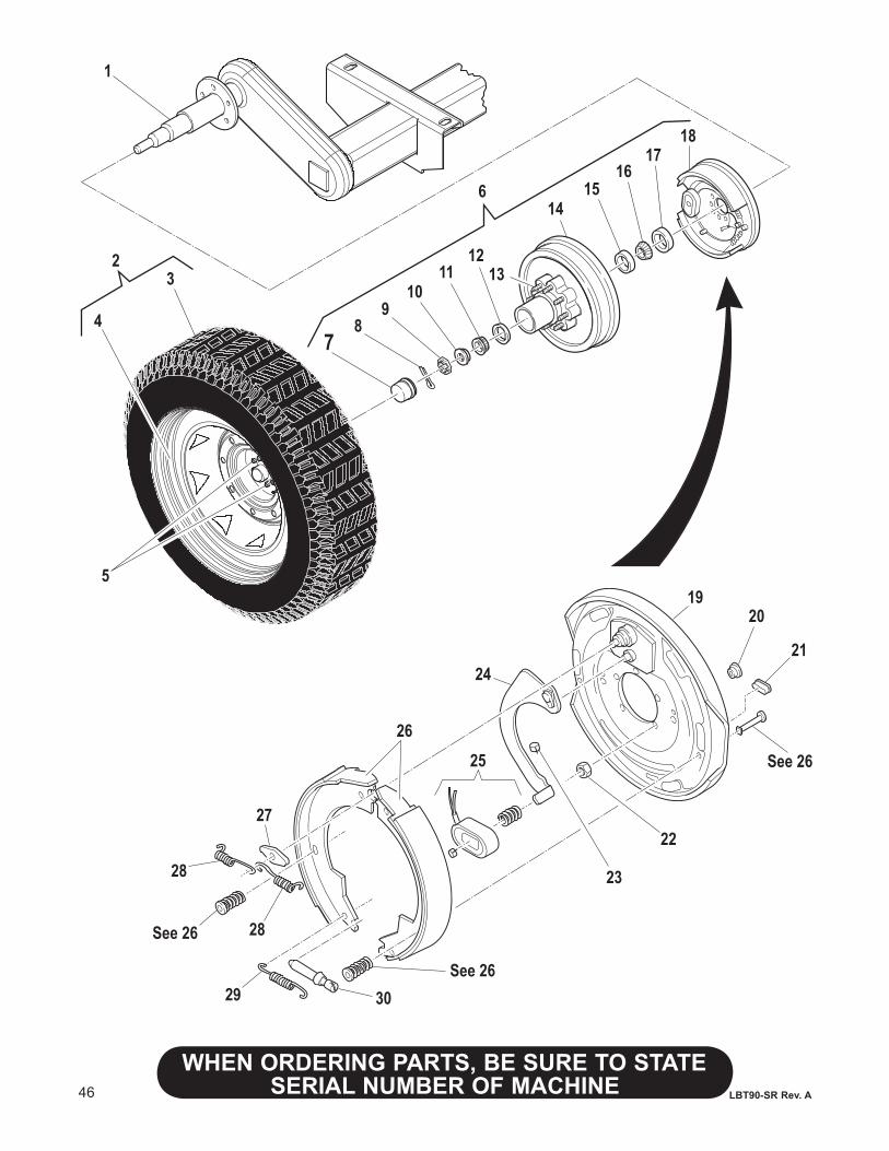
46
WHENORDERINGPARTS,BESURETOSTATESERIAL NUMBER OF MACHINE LBT90-SR Rev. A
1
3
4
6
2
5
7
12
89
1011 13
1415
16
1817
1920
21
See 26
22
23
25
24
26
27
28
29
28
30
See 26
See 26
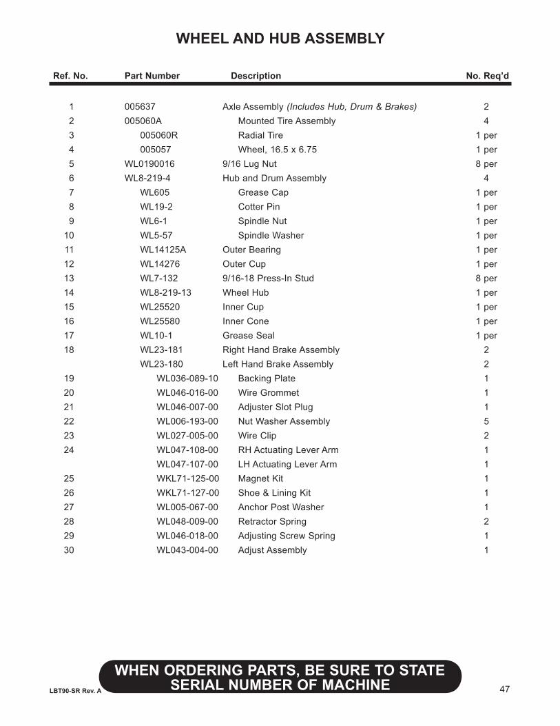
47
WHENORDERINGPARTS,BESURETOSTATESERIAL NUMBER OF MACHINELBT90-SR Rev. A
WHEEL AND HUB ASSEMBLY
Ref.No. PartNumber Description No.Req’d
1 005637 Axle Assembly (Includes Hub, Drum & Brakes) 2 2 005060A Mounted Tire Assembly 4 3 005060R Radial Tire 1 per 4 005057 Wheel, 16.5 x 6.75 1 per 5 WL0190016 9/16 Lug Nut 8 per 6 WL8-219-4 Hub and Drum Assembly 4 7 WL605 Grease Cap 1 per 8 WL19-2 Cotter Pin 1 per 9 WL6-1 Spindle Nut 1 per 10 WL5-57 Spindle Washer 1 per 11 WL14125A Outer Bearing 1 per 12 WL14276 Outer Cup 1 per 13 WL7-132 9/16-18 Press-In Stud 8 per 14 WL8-219-13 Wheel Hub 1 per 15 WL25520 Inner Cup 1 per 16 WL25580 Inner Cone 1 per 17 WL10-1 Grease Seal 1 per 18 WL23-181 Right Hand Brake Assembly 2 WL23-180 Left Hand Brake Assembly 2 19 WL036-089-10 Backing Plate 1 20 WL046-016-00 Wire Grommet 1 21 WL046-007-00 Adjuster Slot Plug 1 22 WL006-193-00 Nut Washer Assembly 5 23 WL027-005-00 Wire Clip 2 24 WL047-108-00 RH Actuating Lever Arm 1 WL047-107-00 LH Actuating Lever Arm 1 25 WKL71-125-00 Magnet Kit 1 26 WKL71-127-00 Shoe & Lining Kit 1 27 WL005-067-00 Anchor Post Washer 1 28 WL048-009-00 Retractor Spring 2 29 WL046-018-00 Adjusting Screw Spring 1 30 WL043-004-00 Adjust Assembly 1
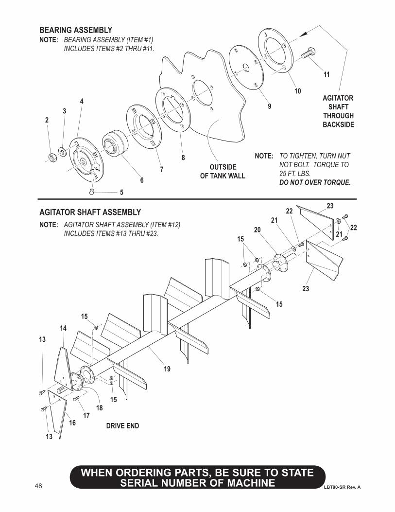
48
WHENORDERINGPARTS,BESURETOSTATESERIAL NUMBER OF MACHINE LBT90-SR Rev. A
BEARING ASSEMBLYNOTE: BEARING ASSEMBLY (ITEM #1) INCLUDES ITEMS #2 THRU #11.
23
4
56
78
OUTSIDEOF TANK WALL
AGITATORSHAFT
THROUGHBACKSIDE
9
10
11
NOTE: TO TIGHTEN, TURN NUT NOT BOLT. TORQUE TO 25 FT. LBS. DO NOT OVER TORQUE.
AGITATOR SHAFT ASSEMBLYNOTE: AGITATOR SHAFT ASSEMBLY (ITEM #12) INCLUDES ITEMS #13 THRU #23.
1314
15
13
1617
1815
19
1520
2122
23
2221
23
15
DRIVE END
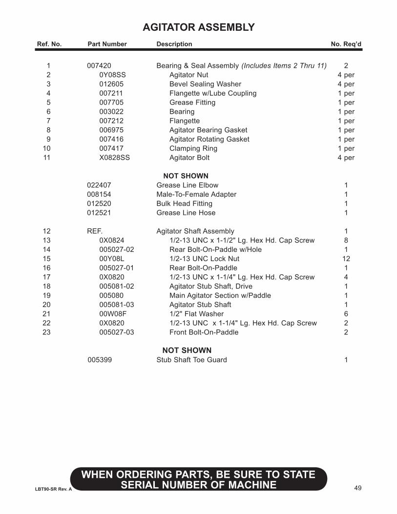
49
WHENORDERINGPARTS,BESURETOSTATESERIAL NUMBER OF MACHINELBT90-SR Rev. A
AGITATOR ASSEMBLYRef.No. PartNumber Description No.Req’d
1 007420 Bearing & Seal Assembly (Includes Items 2 Thru 11) 2 2 0Y08SS Agitator Nut 4 per 3 012605 Bevel Sealing Washer 4 per 4 007211 Flangette w/Lube Coupling 1 per 5 007705 Grease Fitting 1 per 6 003022 Bearing 1 per 7 007212 Flangette 1 per 8 006975 Agitator Bearing Gasket 1 per 9 007416 Agitator Rotating Gasket 1 per 10 007417 Clamping Ring 1 per 11 X0828SS Agitator Bolt 4 per NOT SHOWN 022407 Grease Line Elbow 1 008154 Male-To-Female Adapter 1 012520 Bulk Head Fitting 1 012521 Grease Line Hose 1
12 REF. Agitator Shaft Assembly 1 13 0X0824 1/2-13 UNC x 1-1/2" Lg. Hex Hd. Cap Screw 8 14 005027-02 Rear Bolt-On-Paddle w/Hole 1 15 00Y08L 1/2-13 UNC Lock Nut 12 16 005027-01 Rear Bolt-On-Paddle 1 17 0X0820 1/2-13 UNC x 1-1/4" Lg. Hex Hd. Cap Screw 4 18 005081-02 Agitator Stub Shaft, Drive 1 19 005080 Main Agitator Section w/Paddle 1 20 005081-03 Agitator Stub Shaft 1 21 00W08F 1/2" Flat Washer 6 22 0X0820 1/2-13 UNC x 1-1/4" Lg. Hex Hd. Cap Screw 2 23 005027-03 Front Bolt-On-Paddle 2
NOT SHOWN 005399 Stub Shaft Toe Guard 1
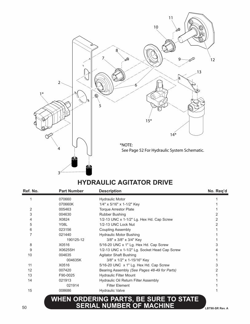
50
WHENORDERINGPARTS,BESURETOSTATESERIAL NUMBER OF MACHINE LBT90-SR Rev. A
HYDRAULIC AGITATOR DRIVE
1*
2
4
5
7
8
6
9
10
11
12
3
13
14*
15*
*NOTE: See Page 52 For Hydraulic System Schematic.
Ref.No. PartNumber Description No.Req’d
1 070660 Hydraulic Motor 1 070660K 1/4" x 5/16" x 1-1/2" Key 1 2 005463 Torque Arrestor Plate 1 3 004630 Rubber Bushing 2 4 X0824 1/2-13 UNC x 1-1/2" Lg. Hex Hd. Cap Screw 2 5 Y08L 1/2-13 UNC Lock Nut 2 6 023156 Coupling Assembly 1 7 021440 Hydraulic Motor Bushing 1 190125-12 3/8" x 3/8" x 3/4" Key 1 8 X0516 5/16-20 UNC x 1" Lg. Hex Hd. Cap Screw 3 9 X0625SH 1/2-13 UNC x 1-1/2" Lg. Socket Head Cap Screw 4 10 004635 Agitator Shaft Bushing 1 004635K 3/8" x 1/2" x 1-15/16" Key 1 11 X0516 5/16-20 UNC x 1" Lg. Hex Hd. Cap Screw 3 12 007420 Bearing Assembly (See Pages 48-49 for Parts) 2 13 F90-0025 Hydraulic Filter Mount 1 14 021913 Hydraulic Oil Return Filter Assembly 1 021914 Filter Element 1 15 008686 Hydraulic Valve 1
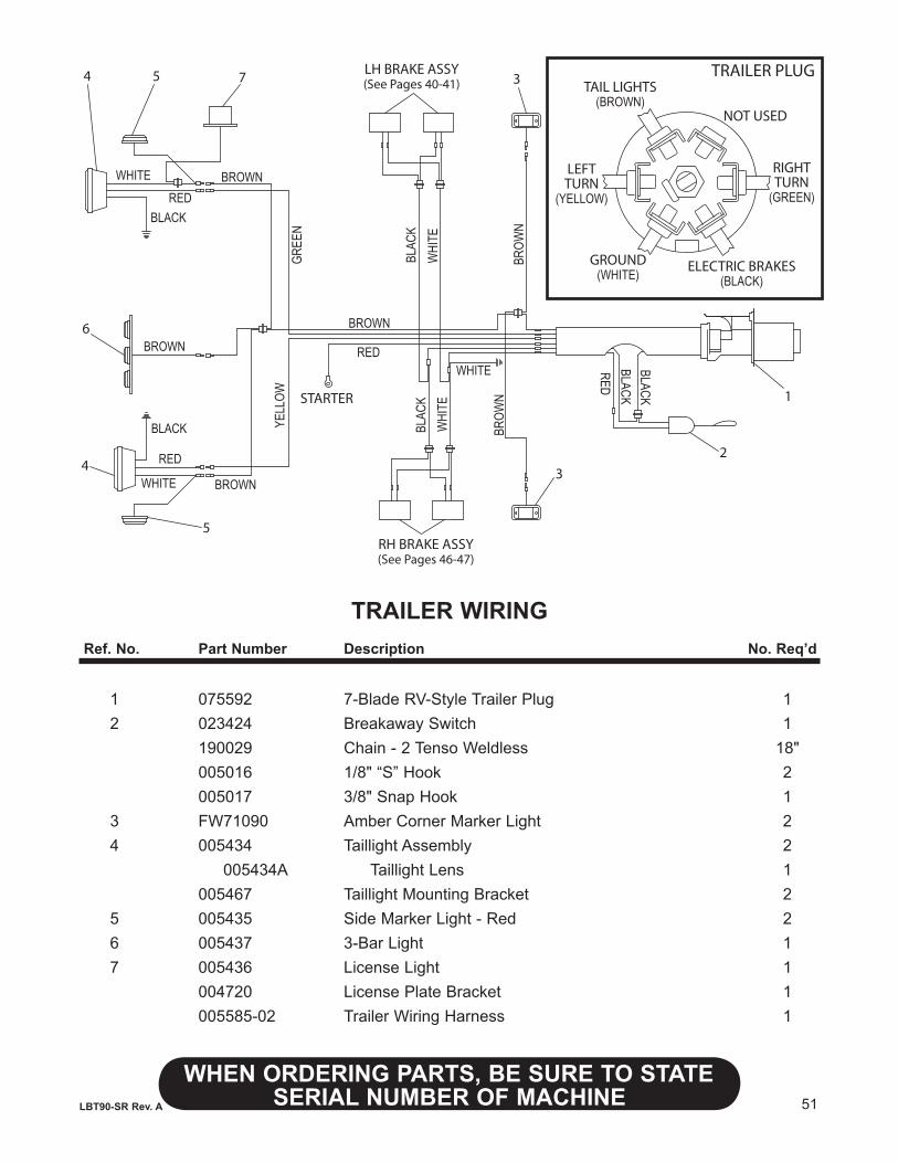
51
WHENORDERINGPARTS,BESURETOSTATESERIAL NUMBER OF MACHINELBT90-SR Rev. A
TRAILER WIRINGRef.No. PartNumber Description No.Req’d
1 075592 7-Blade RV-Style Trailer Plug 1 2 023424 Breakaway Switch 1 190029 Chain - 2 Tenso Weldless 18" 005016 1/8" “S” Hook 2 005017 3/8" Snap Hook 1 3 FW71090 Amber Corner Marker Light 2 4 005434 Taillight Assembly 2 005434A Taillight Lens 1 005467 Taillight Mounting Bracket 2 5 005435 Side Marker Light - Red 2 6 005437 3-Bar Light 1 7 005436 License Light 1 004720 License Plate Bracket 1 005585-02 Trailer Wiring Harness 1
BROW
N
RED
RED
BLACK
BLACK
WHITE
WHITE
GREE
NYE
LLOW STARTER
BLACK
BROWN
BROWN
WHITE
1
2
BROW
N
BROWN
BROWN
RED
RED
BLACK BLAC
KW
HITE
WHI
TEBL
ACK
3
3
4
4
5
5
6
7LH BRAKE ASSY(See Pages 40-41)
RH BRAKE ASSY(See Pages 46-47)
NOT USED
RIGHTTURN
(GREEN)
ELECTRIC BRAKES(BLACK)
GROUND(WHITE)
LEFTTURN
(YELLOW)
TAIL LIGHTS(BROWN)
TRAILER PLUG
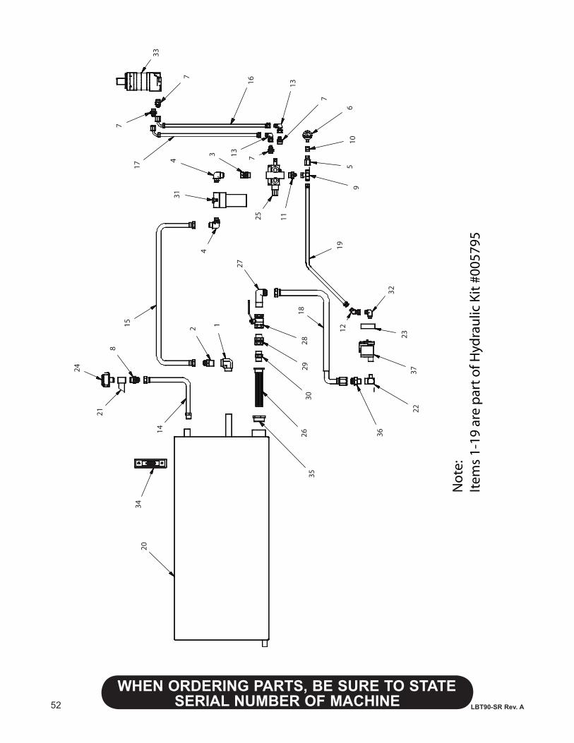
52
WHENORDERINGPARTS,BESURETOSTATESERIAL NUMBER OF MACHINE LBT90-SR Rev. A
13
7
13
167
25 11
96
105
314
34
1517
7
1219
32
23
22
36
18
37
27
3029
28
3420
78
24
21
352614
2 1
33
No
te:
Item
s 1-
19 a
re p
art
of H
ydra
ulic
Kit
#00
5795
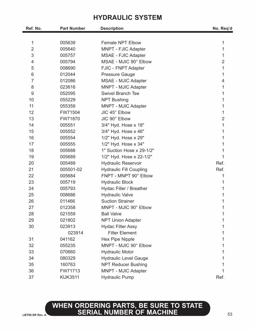
53
WHENORDERINGPARTS,BESURETOSTATESERIAL NUMBER OF MACHINELBT90-SR Rev. A
HYDRAULIC SYSTEM Ref.No. PartNumber Description No.Req’d
1 005639 Female NPT Elbow 1 2 005640 MNPT - FJIC Adapter 1 3 005757 MSAE - FJIC Adapter 1 4 005794 MSAE - MJIC 90° Elbow 2 5 008690 FJIC - FNPT Adapter 1 6 012044 Pressure Gauge 1 7 012086 MSAE - MJIC Adapter 4 8 023616 MNPT - MJIC Adapter 1 9 052095 Swivel Branch Tee 1 10 055229 NPT Bushing 1 11 055359 MNPT - MJIC Adapter 1 12 FW71504 JIC 45° Elbow 1 13 FW71870 JIC 90° Elbow 2 14 005551 3/4" Hyd. Hose x 18" 1 15 005552 3/4" Hyd. Hose x 46" 1 16 005554 1/2" Hyd. Hose x 29" 1 17 005555 1/2" Hyd. Hose x 34" 1 18 005688 1" Suction Hose x 29-1/2" 1 19 005689 1/2" Hyd. Hose x 22-1/2" 1 20 005489 Hydraulic Reservoir Ref. 21 005501-02 Hydraulic Fill Coupling Ref. 22 005684 FNPT - MNPT 90° Elbow 1 23 005719 Hydraulic Block 1 24 005793 Hydac Filler / Breather 1 25 008686 Hydraulic Valve 1 26 011466 Suction Strainer 1 27 012358 MNPT - MJIC 90° Elbow 1 28 021559 Ball Valve 1 29 021802 NPT Union Adapter 1 30 023913 Hydac Filter Assy 1 023914 Filter Element 1 31 041162 Hex Pipe Nipple 1 32 055235 MNPT - MJIC 90° Elbow 1 33 070660 Hydraulic Motor 1 34 080329 Hydraulic Level Gauge 1 35 160763 NPT Reducer Bushing 1 36 FW71713 MNPT - MJIC Adapter 1 37 KUK3511 Hydraulic Pump Ref.
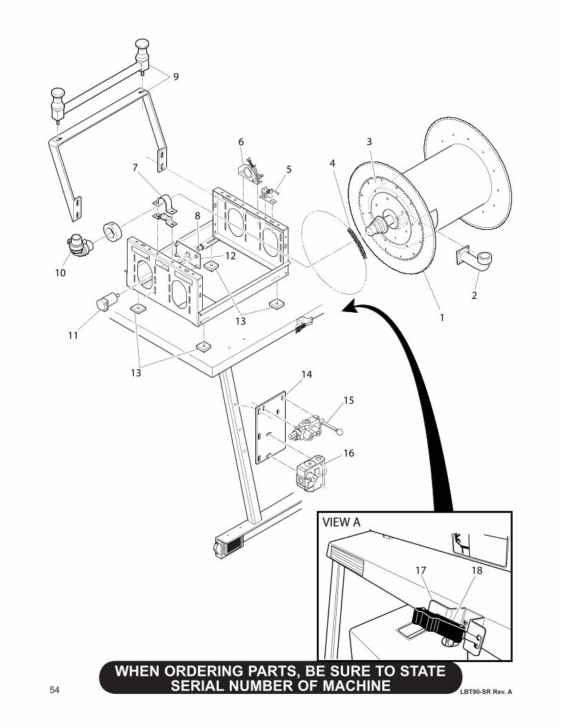
54
WHENORDERINGPARTS,BESURETOSTATESERIAL NUMBER OF MACHINE LBT90-SR Rev. A
17 18
VIEW A
6
1
2
3
457
9
10
11
8
13
13
12
14
15
16
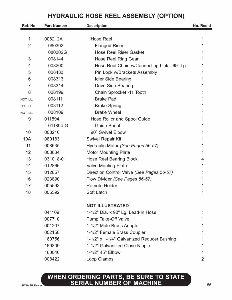
55
WHENORDERINGPARTS,BESURETOSTATESERIAL NUMBER OF MACHINELBT90-SR Rev. A
HYDRAULIC HOSE REEL ASSEMBLY (OPTION)Ref.No. PartNumber Description No.Req’d
1 008212A Hose Reel 1 2 080302 Flanged Riser 1 080302G Hose Reel Riser Gasket 1 3 008144 Hose Reel Ring Gear 1 4 008200 Hose Reel Chain w/Connecting Link - 69" Lg. 1 5 008433 Pin Lock w/Brackets Assembly 1 6 008313 Idler Side Bearing 1 7 008314 Drive Side Bearing 1 8 008199 Chain Sprocket -11 Tooth 1 NOT ILL. 008111 Brake Pad 1 NOT ILL. 008112 Brake Spring 1 NOT ILL. 008109 Brake Wheel 1 9 011894 Hose Roller and Spool Guide 1 011894-G Guide Spool 1 10 008210 90º Swivel Elbow 1 10A 080183 Swivel Repair Kit 1 11 008635 Hydraulic Motor (See Pages 56-57) 1 12 008634 Motor Mounting Plate 1 13 031018-01 Hose Reel Bearing Block 4 14 012866 Valve Mouting Plate 1 15 012857 Direction Control Valve (See Pages 56-57) 1 16 023890 Flow Divider (See Pages 56-57) 1 17 005593 Remote Holder 1 18 005592 Soft Latch 1
NOT ILLUSTRATED 041109 1-1/2" Dia. x 90" Lg. Lead-In Hose 1 007710 Pump Take-Off Valve 1 001207 1-1/2" Male Brass Adapter 1 002158 1-1/2" Female Brass Coupler 1 160756 1-1/2" x 1-1/4" Galvanized Reducer Bushing 1 160309 1-1/2" Galvanized Close Nipple 1 160040 1-1/2" 45º Elbow 1 008422 Loop Clamps 2
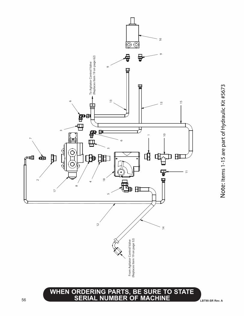
56
WHENORDERINGPARTS,BESURETOSTATESERIAL NUMBER OF MACHINE LBT90-SR Rev. A
Not
e: It
ems
1-15
are
par
t of H
ydra
ulic
Kit
#567
3
913
8
4 18
1
7
6
3
6
3
12
5
1416
11
15
10
2
913
17
To A
git
ato
r C
on
tro
l Val
ve(R
epla
ces
Item
19
on
pag
e 62
)
Fro
m A
git
ato
r C
on
tro
l Val
ve(R
epla
ces
Item
19
on
pag
e 52
)
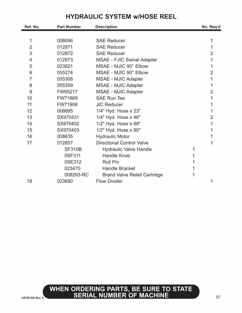
57
WHENORDERINGPARTS,BESURETOSTATESERIAL NUMBER OF MACHINELBT90-SR Rev. A
HyDRAULICSySTEMw/HOSEREEL Ref.No. PartNumber Description No.Req’d
1 008696 SAE Reducer 1 2 012871 SAE Reducer 1 3 012872 SAE Reducer 2 4 012873 MSAE - FJIC Swivel Adapter 1 5 023621 MSAE - MJIC 90° Elbow 1 6 055274 MSAE - MJIC 90° Elbow 2 7 055308 MSAE - MJIC Adapter 1 8 055359 MSAE - MJIC Adapter 1 9 FW65217 MSAE - MJIC Adapter 2 10 FW71869 SAE Run Tee 1 11 FW71908 JIC Reducer 1 12 008695 1/4" Hyd. Hose x 23" 1 13 SX970331 1/4" Hyd. Hose x 46" 2 14 SX970402 1/2" Hyd. Hose x 68" 1 15 SX970403 1/2" Hyd. Hose x 80" 1 16 008635 Hydraulic Motor 1 17 012857 Directional Control Valve 1 SF310B Hydraulic Valve Handle 1 0SF311 Handle Knob 1 0SE312 Roll Pin 1 023470 Handle Bracket 1 008293-RC Brand Valve Relief Cartridge 1 18 023890 Flow Divider 1
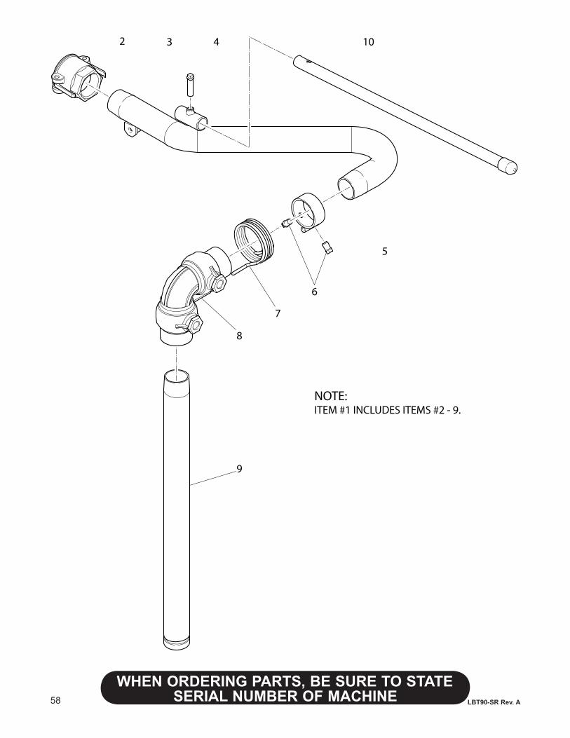
58
WHENORDERINGPARTS,BESURETOSTATESERIAL NUMBER OF MACHINE LBT90-SR Rev. A
2 3 4 10
5
6
7
8
9
NOTE:ITEM #1 INCLUDES ITEMS #2 - 9.
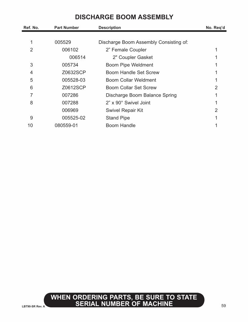
59
WHENORDERINGPARTS,BESURETOSTATESERIAL NUMBER OF MACHINELBT90-SR Rev. A
DISCHARGE BOOM ASSEMBLYRef.No. PartNumber Description No.Req’d
1 005529 Discharge Boom Assembly Consisting of: 2 006102 2” Female Coupler 1 006514 2" Coupler Gasket 1 3 005734 Boom Pipe Weldment 1 4 Z0632SCP Boom Handle Set Screw 1 5 005528-03 Boom Collar Weldment 1 6 Z0612SCP Boom Collar Set Screw 2 7 007286 Discharge Boom Balance Spring 1 8 007288 2” x 90° Swivel Joint 1 006969 Swivel Repair Kit 2 9 005525-02 Stand Pipe 1 10 080559-01 Boom Handle 1
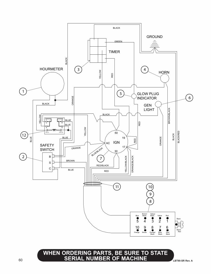
60
WHENORDERINGPARTS,BESURETOSTATESERIAL NUMBER OF MACHINE LBT90-SR Rev. A
B
S
C
50
17
19
30
AC
BLACK
RE
D
RED
YE
LLO
W
YE
LLO
W/B
LAC
K
BR
OW
N/B
LAC
K
BLU
E
BLUE
RED/BLACK
BLUE/BLACK
OR
AN
GE
/BLA
CK
BROWN
ORANGE
OR
AN
GE
BLA
CK
BLA
CK
/RE
D
RE
D
OR
AN
GE
BLA
CK
GREEN
RE
D
YE
LLO
W
BLACK
HOURMETER
GROUND
TIMER
HORN
GLOW PLUG INDICA T OR
GENLIGHT
IGNSAFETY SWITCH
5 4 3 2 1
10 9 8 7 6
BlueBrown/Black
Y ellow/Black Y ellow Red
Orange Brown Orange/Black
Blue/Black
Red/Black
Black
RedBlack/
65
YE
LLO
W
BLUE
BLUE
BLUE
BLACK
10
9
8
11
7
43
2
1
1
5
9
4
8
12
13 (-) 14 (+)
12
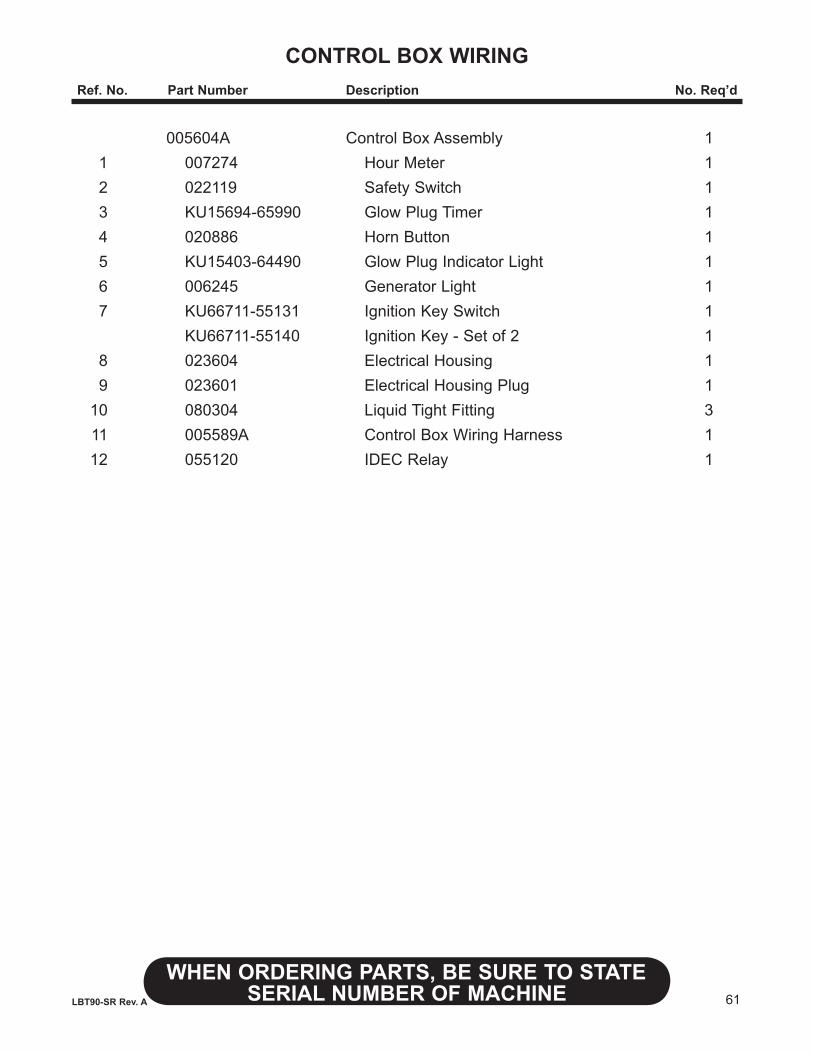
61
WHENORDERINGPARTS,BESURETOSTATESERIAL NUMBER OF MACHINELBT90-SR Rev. A
CONTROL BOX WIRINGRef.No. PartNumber Description No.Req’d
005604A Control Box Assembly 1 1 007274 Hour Meter 1 2 022119 Safety Switch 1 3 KU15694-65990 Glow Plug Timer 1 4 020886 Horn Button 1 5 KU15403-64490 Glow Plug Indicator Light 1 6 006245 Generator Light 1 7 KU66711-55131 Ignition Key Switch 1 KU66711-55140 Ignition Key - Set of 2 1 8 023604 Electrical Housing 1 9 023601 Electrical Housing Plug 1 10 080304 Liquid Tight Fitting 3 11 005589A Control Box Wiring Harness 1 12 055120 IDEC Relay 1
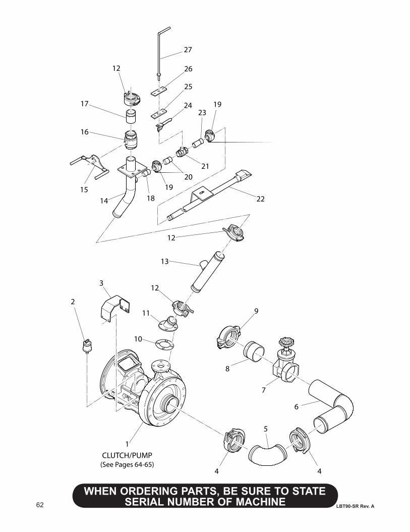
62
WHENORDERINGPARTS,BESURETOSTATESERIAL NUMBER OF MACHINE LBT90-SR Rev. A
1
2
3
4 4
5
7
8
6
9
10
11
12
12
1415
16
17
12
1819
2021
24
25
26
27
2319
22
CLUTCH/PUMP(See Pages 64-65)
13
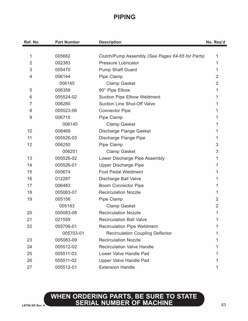
63
WHENORDERINGPARTS,BESURETOSTATESERIAL NUMBER OF MACHINELBT90-SR Rev. A
PIPING
Ref.No. PartNumber Description No.Req’d
1 005682 Clutch/Pump Assembly (See Pages 64-65 for Parts) 1 2 002383 Pressure Lubricator 1 3 005470 Pump Shaft Guard 1 4 006144 Pipe Clamp 2 006145 Clamp Gasket 2 5 006359 90° Pipe Elbow 1 6 005524-02 Suction Pipe Elbow Weldment 1 7 008280 Suction Line Shut-Off Valve 1 8 005523-06 Connector Pipe 1 9 006710 Pipe Clamp 1 006145 Clamp Gasket 1 10 008469 Discharge Flange Gasket 1 11 005526-03 Discharge Flange Pipe 1 12 006250 Pipe Clamp 3 006251 Clamp Gasket 3 13 005526-02 Lower Discharge Pipe Assembly 1 14 005526-01 Upper Discharge Pipe 1 15 005674 Foot Pedal Weldment 1 16 012287 Discharge Ball Valve 1 17 006483 Boom Connector Pipe 1 18 005083-07 Recirculation Nozzle 1 19 005156 Pipe Clamp 2 005183 Clamp Gasket 2 20 005083-08 Recirculation Nozzle 1 21 021559 Recirculation Ball Valve 1 22 005706-01 Recirculation Pipe Weldment 1 005703-01 Recirculation Coupling Deflector 1 23 005083-09 Recirculation Nozzle 1 24 005512-02 Recirculation Valve Handle 1 25 005511-03 Lower Valve Handle Pad 1 26 005511-02 Upper Valve Handle Pad 1 27 005512-01 Extension Handle 1
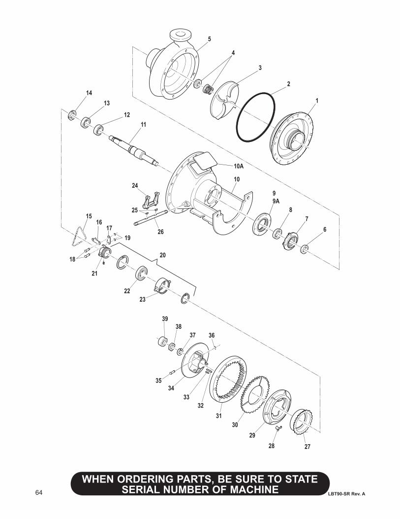
64
WHENORDERINGPARTS,BESURETOSTATESERIAL NUMBER OF MACHINE LBT90-SR Rev. A
1
5
3
2
4
6
99A
78
10
11
14
12
13
19
20
24
25
26
22
1516
17
18
23
21
272829
3031
3233
3435
363738
39
10A
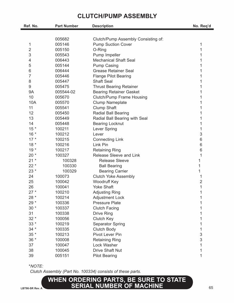
65
WHENORDERINGPARTS,BESURETOSTATESERIAL NUMBER OF MACHINELBT90-SR Rev. A
CLUTCH/PUMPASSEMBLy Ref.No. PartNumber Description No.Req’d
005682 Clutch/Pump Assembly Consisting of: 1 005146 Pump Suction Cover 1 2 005150 O-Ring 1 3 005543 Pump Impeller 1 4 006443 Mechanical Shaft Seal 1 5 005144 Pump Casing 1 6 006444 Grease Retainer Seal 1 7 005446 Flange Pilot Bearing 1 8 005447 Shaft Seal 1 9 005475 Thrust Bearing Retainer 1 9A 005544-02 Bearing Retainer Gasket 1 10 005670 Clutch/Pump Frame Housing 1 10A 005570 Clump Nameplate 1 11 005541 Clump Shaft 1 12 005450 Radial Ball Bearing 1 13 005449 Radial Ball Bearing with Seal 1 14 005448 Bearing Locknut 1 15 * 100211 Lever Spring 1 16 * 100212 Lever 3 17 * 100215 Connecting Link 6 18 * 100216 Link Pin 6 19 * 100217 Retaining Ring 6 20 * 100327 Release Sleeve and Link 1 21 * 100328 Release Sleeve 1 22 * 100330 Ball Bearing 1 23 * 100329 Bearing Carrier 1 24 100073 Clutch Yoke Assembly 1 25 100042 Woodruff Key 2 26 100041 Yoke Shaft 1 27 * 100210 Adjusting Ring 1 28 * 100214 Adjustment Lock 1 29 * 100336 Pressure Plate 1 30 * 100337 Clutch Facing 1 31 100338 Drive Ring 1 32 * 100056 Clutch Key 1 33 * 100219 Separator Spring 1 34 * 100335 Clutch Body 1 35 * 100213 Pivot Lever Pin 3 36 * 100008 Retaining Ring 3 37 100047 Lock Washer 1 38 100045 Drive Shaft Nut 1 39 005151 Pilot Bearing 1
*NOTE: Clutch Assembly (Part No. 100334) consists of these parts.
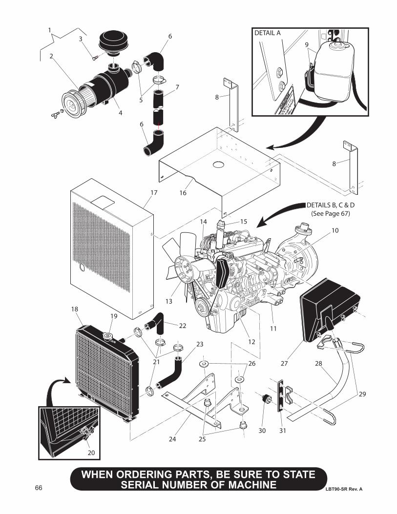
66
WHENORDERINGPARTS,BESURETOSTATESERIAL NUMBER OF MACHINE LBT90-SR Rev. A
DETAIL A
9
8
8
10
DETAILS B, C & D(See Page 67)
11
12
13
14 15
1617
18
21
22
23
2524
26 2827
29
3130
20
19
13
2
5
4
6
7
6
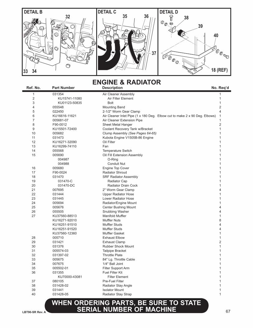
67
WHENORDERINGPARTS,BESURETOSTATESERIAL NUMBER OF MACHINELBT90-SR Rev. A
ENGINE&RADIATOR Ref.No. PartNumber Description No.Req’d 1 031354 Air Cleaner Assembly 1 2 KU15741-11080 Air Filter Element 1 3 KU01123-50835 Bolt 1 4 055548 Mounting Band 2 5 022450 2-1/2" Worm Gear Clamp 4 6 KU16616-11621 Air Cleaner Inlet Pipe (1 x 180 Deg. Elbow cut to make 2 x 90 Deg. Elbows) 1 7 005681-07 Air Cleaner Extension Pipe 1 8 F90-0012 Sheet Metal Hanger 2 9 KU15501-72400 Coolant Recovery Tank w/Bracket 1 10 005682 Clump Assembly (See Pages 64-65) 1 11 031473 Kubota Engine V1505B-86 Engine 1 12 KU16271-32090 Oil Filter 1 13 KU16299-74110 Fan 1 14 055568 Temperature Switch 1 15 005690 Oil Fill Extension Assembly 1 004987 O-Ring 1 004988 Conduit Nut 1 16 005680 Engine Top Cover 1 17 F90-0024 Radiator Shroud 1 18 031470 SRF Radiator Assembly 1 19 031470-C Radiator Cap 1 20 031470-DC Radiator Drain Cock 1 21 007695 2" Worm Gear Clamp 4 22 031444 Upper Radiator Hose 1 23 031445 Lower Radiator Hose 1 24 005694 Radiator/Engine Mount 1 25 005676 Center Bushing Mount 4 26 055505 Snubbing Washer 4 27 KU37560-88513 Manifold Muffler 1 KU16271-92010 Muffler Nuts 8 KU16251-91510 Muffler Studs 4 KU16251-91520 Muffler Studs 4 KU37560-12360 Muffler Gasket 1 28 005710 Exhaust Elbow 1 29 031421 Exhaust Clamp 2 30 031376 Rubber Shock Mount 1 31 005574-03 Tailpipe Bracket 1 32 031397-02 Throttle Plate 1 33 005675 84" Lg. Throttle Cable 1 34 007675 1/4" Ball Joint 1 35 005502-01 Filter Support Arm 1 36 031355 Fuel Filter Kit 1 KU70000-43081 Filter Element 1 37 080105 Pre-Fuel Filter 1 38 031428-02 Radiator Stay Angle 1 39 031441 Isolator Mount 1 40 031428-05 Radiator Stay Strap 1
DETAIL B DETAIL C32
33 34
35 36
37
DETAIL D38
39
40
18 (REF)
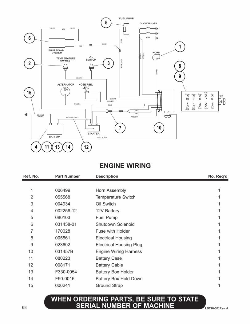
68
WHENORDERINGPARTS,BESURETOSTATESERIAL NUMBER OF MACHINE LBT90-SR Rev. A
ENGINE WIRINGRef.No. PartNumber Description No.Req’d
1 006499 Horn Assembly 1 2 055568 Temperature Switch 1 3 004934 Oil Switch 1 4 002256-12 12V Battery 1 5 080103 Fuel Pump 1 6 031458-01 Shutdown Solenoid 1 7 170028 Fuse with Holder 1 8 005561 Electrical Housing 1 9 023602 Electrical Housing Plug 1 10 031457B Engine Wiring Harness 1 11 080223 Battery Case 1 12 008171 Battery Cable 1 13 F330-0054 Battery Box Holder 1 14 F90-0016 Battery Box Hold Down 1 15 000241 Ground Strap 1
5030
STARTERBATTERY
ALTERNATOR
GLOW PLUGS
FUEL PUMP
HORN
TEMPERATURESWITCH
OILSWITCH
BATTERY CABLEGROUNDSTRAP
12 Ga. B
LUE
BROWN
WHITE
YELLOW
GR
EE
N
BLACK
ORANGE
BLA
CK
RED
12 Ga. BLACK
BROWN
BLUE
RED
5 4 3 2 110 9 8 7 6
Orange Brown Green Blue Red
Blue Black Green Yellow Red
Black12 Ga.
16 Ga.12 Ga.
16 Ga.
RED
GR
EE
N
BLUE
SHUT DOWNSYSTEM
BLUE
WHITE
6
2
7
HOSE REELLEAD
15
4 11 13 14 12
3
5
10
1
8
9
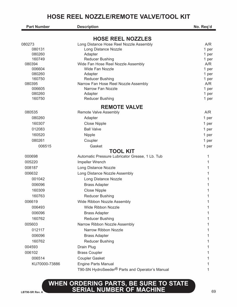
69
WHENORDERINGPARTS,BESURETOSTATESERIAL NUMBER OF MACHINELBT90-SR Rev. A
HOSEREELNOzzLE/REMOTEVALVE/TOOLKIT PartNumber Description No.Req’d
HOSEREELNOzzLES 080273 Long Distance Hose Reel Nozzle Assembly A/R 080131 Long Distance Nozzle 1 per 080260 Adapter 1 per 160749 Reducer Bushing 1 per 080394 Wide Fan Hose Reel Nozzle Assembly A/R 006604 Wide Fan Nozzle 1 per 080260 Adapter 1 per 160750 Reducer Bushing 1 per 080395 Narrow Fan Hose Reel Nozzle Assembly A/R 006605 Narrow Fan Nozzle 1 per 080260 Adapter 1 per 160750 Reducer Bushing 1 per
REMOTE VALVE 080535 Remote Valve Assembly A/R 080260 Adapter 1 per 160307 Close Nipple 1 per 012083 Ball Valve 1 per 160520 Nipple 1 per 080261 Coupler 1 per 006515 Gasket 1 per TOOL KIT 000698 Automatic Pressure Lubricator Grease, 1 Lb. Tub 1 005220 Impeller Wrench 1 008187 Long Distance Nozzle 1 006632 Long Distance Nozzle Assembly 1 001042 Long Distance Nozzle 1 006096 Brass Adapter 1 160309 Close Nipple 1 160763 Reducer Bushing 1 006619 Wide Ribbon Nozzle Assembly 1 006493 Wide Ribbon Nozzle 1 006096 Brass Adapter 1 160762 Reducer Bushing 1 005603 Narrow Ribbon Nozzle Assembly 1 012117 Narrow Ribbon Nozzle 1 006096 Brass Adapter 1 160762 Reducer Bushing 1 004593 Drain Plug 1 006102 Brass Coupler 1 006514 Coupler Gasket 1 KU70000-73886 Engine Parts Manual 1 T90-SN HydroSeeder® Parts and Operator’s Manual 1
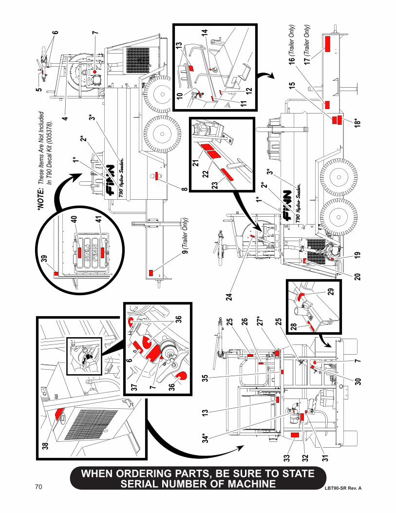
70
WHENORDERINGPARTS,BESURETOSTATESERIAL NUMBER OF MACHINE LBT90-SR Rev. A
39
40 41
5
6 7
89
1013
1112
14
1516
18*
1920
2425 27
*
25
7
313233
34*
1335
38
4
2322
21
37 7 36
6
36
28
29
30
26
1*2*
3*
1*2*
3*
(Tra
iler O
nly)
17(T
raile
r Only
)
(Tra
iler O
nly)
*NOT
E: T
hese
Item
s Are
Not
Inclu
ded
I
n T9
0 De
cal K
it (00
5378
).
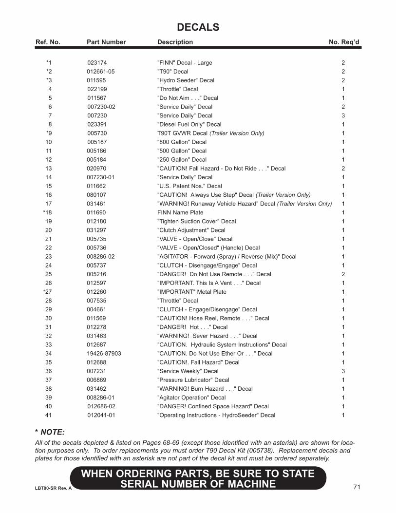
71
WHENORDERINGPARTS,BESURETOSTATESERIAL NUMBER OF MACHINELBT90-SR Rev. A
DECALSRef.No. PartNumber Description No.Req’d
*1 023174 "FINN" Decal - Large 2 *2 012661-05 "T90" Decal 2 *3 011595 "Hydro Seeder" Decal 2 4 022199 "Throttle" Decal 1 5 011567 "Do Not Aim . . ." Decal 1 6 007230-02 "Service Daily" Decal 2 7 007230 "Service Daily" Decal 3 8 023391 "Diesel Fuel Only" Decal 1 *9 005730 T90T GVWR Decal (Trailer Version Only) 1 10 005187 "800 Gallon" Decal 1 11 005186 "500 Gallon" Decal 1 12 005184 "250 Gallon" Decal 1 13 020970 "CAUTION! Fall Hazard - Do Not Ride . . ." Decal 2 14 007230-01 "Service Daily" Decal 1 15 011662 "U.S. Patent Nos." Decal 1 16 080107 "CAUTION! Always Use Step" Decal (Trailer Version Only) 1 17 031461 "WARNING! Runaway Vehicle Hazard" Decal (Trailer Version Only) 1 *18 011690 FINN Name Plate 1 19 012180 "Tighten Suction Cover" Decal 1 20 031297 "Clutch Adjustment" Decal 1 21 005735 "VALVE - Open/Close" Decal 1 22 005736 "VALVE - Open/Closed" (Handle) Decal 1 23 008286-02 "AGITATOR - Forward (Spray) / Reverse (Mix)" Decal 1 24 005737 "CLUTCH - Disengage/Engage" Decal 1 25 005216 "DANGER! Do Not Use Remote . . ." Decal 2 26 012597 "IMPORTANT. This Is A Vent . . ." Decal 1 *27 012260 "IMPORTANT" Metal Plate 1 28 007535 "Throttle" Decal 1 29 004661 "CLUTCH - Engage/Disengage" Decal 1 30 011569 "CAUTION! Hose Reel, Remote . . ." Decal 1 31 012278 "DANGER! Hot . . ." Decal 1 32 031463 "WARNING! Sever Hazard . . ." Decal 1 33 012687 "CAUTION. Hydraulic System Instructions" Decal 1 34 19426-87903 "CAUTION. Do Not Use Ether Or . . ." Decal 1 35 012688 "CAUTION!. Fall Hazard" Decal 1 36 007231 "Service Weekly" Decal 3 37 006869 "Pressure Lubricator" Decal 1 38 031462 "WARNING! Burn Hazard . . ." Decal 1 39 008286-01 "Agitator Operation" Decal 1 40 012686-02 "DANGER! Confined Space Hazard" Decal 1 41 012041-01 "Operating Instructions - HydroSeeder" Decal 1
* NOTE:All of the decals depicted & listed on Pages 68-69 (except those identified with an asterisk) are shown for loca-tion purposes only. To order replacements you must order T90 Decal Kit (005738). Replacement decals and plates for those identified with an asterisk are not part of the decal kit and must be ordered separately.