Embed Size (px)
Citation preview
© TA2 Consortium 2011 Page 1 of (53)
ICT-214793
TA2
Together Anywhere, Together Anytime
Large Scale Integrating Project
ICT – Networked Media
D4.5 Component Architecture
Due date of deliverable: 30 September 2011
Actual submission date: 7 November 2011
Start date of project: 1 February 2008 Duration: 48 months
Lead contractor for this deliverable: ALC
Version for submission of 27 October 2011
Confidentiality status: “Public”
Ref. Ares(2011)1185095 - 08/11/2011
D4.5 Component Architecture
Page 2 of (53) © TA2 Consortium 2011
Abstract
This document constitutes a final description of the functional architecture of the TA2 platform. It describes the implementation of the different TA2 client and server side components and their communication strategy. Using the different concept demonstrators as basic scenarios, it is shown how these components can be combined to deliver the functionality required in a number of different shared activities that are intended to enable social relationships between groups of people that know each other well to be nurtured. This document is of a ‘public’ nature.
Target audience
This is a public document. It is designed to be read by the wider academic and industrial community interested in the approach taken within TA2 to deliver orchestrated communications between groups of people in several locations.
Disclaimer
This document contains material, which is the copyright of certain TA2 consortium parties, and may not be reproduced or copied without permission. All TA2 consortium parties have agreed to full publication of this document. The commercial use of any information contained in this document may require a license from the proprietor of that information.
Neither the TA2 consortium as a whole, nor a certain party of the TA2 consortium warrant that the information contained in this document is capable of use, or that use of the information is free from risk, and accept no liability for loss or damage suffered by any person using this information.
This document does not represent the opinion of the European Community, and the European Community is not responsible for any use that might be made of its content.
Impressum
Full project title: Together Anywhere, Together Anytime
Title of the workpackage: Application Design and Implementation
Document title: D4.5 Component Architecture
Editor: Orlando Verde, Alcatel-Lucent
Workpackage Leader: Orlando Verde, Alcatel-Lucent
Project Co-ordinator: Peter Stollenmayer, Eurescom
Technical Project Leader: Doug Williams, BT
This project is co-funded by the European Union through the ICT programme under FP7.
Copyright notice
© 2011 Participants in project TA2
Confidentiality status: “Public”
D4.5 Component Architecture
© TA2 Consortium 2011 Page 3 of (53)
Executive SummaryThis document describes the technical architecture used in the “Together Anywhere, Together Anytime”(TA2) project to support a range of concept demonstrators that are designed to enhance social relationships between remote groups of people who know each other well. The concept demonstrators include a shared activity, which provides a common focus for all parties, together with the ability to communicate in real time.
The main technical components are described and the document shows how, in different configurations,the architecture can support a range of different real time shared communications. The architecture is capable of handling both real time and recorded streams of both audio and video and of compositing these inputs at each end point independently. In addition, the architecture is able to intelligently decide how to compose the video output at each end based on analysis of the audio and video signals.
Both the architecture and the functionality of the main components of the architecture are described.
The key capabilities that the architecture supports include:
HD video: video transmitted at one of the accepted HD resolutions and with minimal delay, that provides peripheral awareness of people at each end and, if necessary, some indication of eye contact and the ability to transmit and interpret gesture and body language.
HD audio: audio transmitted using multichannel (at least stereo) full audio bandwidth (>24 kHz) in order to support relaxed hands free communications with sound presented through HiFi speakers and captured through microphones arrays.
Multiple HD cameras: in order to capture different views of each end.
A shared focus: an activity which is common to all ends of the experience that provides a common fun shared activity that aids in the building of social bonds between the participants.
Orchestration: a means of selecting the camera view that provides the ‘best’ representation of the remote ends to all parties involved in the shared experience.
In turn, these capabilities demand the additional capabilities:
Dynamic Screen Composition: This is the composition (following instructions from the orchestrator) on to one or more screens at each location, of combinations of real-time and file based media including the video streams from the cameras and local or centrally stored media such as elements of the game or shared photos or videos.
Automatic Audio and Video Analysis: Real time analysis of audio and video signals is used by the orchestrator to decide which of the possible combination of sources of media and video streams provides the “best” representation of the shared activity to each end. In addition analysis is also used to control games with gestures and body movements.
The document is prepared as an explanatory guideline for building such systems but is not intended as a complete and rigid blue print. A number of key architectural decisions are identified and the capabilities exhibited by some of the components that make this TA2 architecture, to our knowledge at least, uniquely capable, are described.
D4.5 Component Architecture
Page 4 of (53) © TA2 Consortium 2011
The more notable capabilities of the architecture are derived from the following components:
The Visual Composition Engine, a highly capable composition engine instructed using the Synchronised Multimedia Integration Language (SMIL) that allows very rich visual compositions to be built from a range of different visual sources including real time video streams, recorded video, Flash files and still images.
The Orchestration Engine that interprets cues derived from audio and video analysis and instructs the VCE on how to compose the screen outputs that best represent the shared activity to each endpoint.
The Video Router, a connection matrix between multiple sources and destinations which can replicate and switch streams all under external control. Additionally streams can be recorded and can either be reinserted into the output streams or post processed and made available off line.
The Audio Communication Engine (ACE) which, in combination with the multi way control and appropriately designed microphone and speaker set-ups provides excellent, stable, audio communication channels between all parties.
In allowing these components to operate as an integrated system we recognise and commend the following:
The use of XML –RPC as a cross platform protocol that allows efficient communication between components.
The use of SMIL as a mark-up language that allows multiple media components to be composed both temporally and spatially against a common timeline.
The development of an adaptation to SMIL state to enable the dynamic adaptation of SMIL layouts.
The use of MPEG AAC Enhanced Low Delay (AAC-ELD) as a core component for facilitating HD audio communication.
The logical separation of intelligent functionality into a single entity (the orchestrator) that controls the behaviour of other components.
The separation of client and network functions.
The use of a single component to provide set up, session control and to act as a hub for communications between components.
The use of Python scripts which, in the hands of those suitably skilled, enables simple control scripts to be written to perform “simple” but important system control and set up functions.
Whilst the architecture has been developed from a necessarily limited number of use cases we believe its intrinsically componentised nature means that it can support a wide range of other applications as well and for this reason we believe the insights expressed through this document may well have wide ranging applicability.
D4.5 Component Architecture
© TA2 Consortium 2011 Page 5 of (53)
List of AuthorsCoezijn, Etienne; Philips
Färber, Nikolaus; Fraunhofer IIS
Hughes, Peter; BT
Jansen, Jack; CWI
Kaiser, Rene; Joanneum Research
Kegel, Ian; BT
Korchagin, Danil; IDIAP
Stevens, Tim; BT
Ursu, Marian; Goldsmiths, University of London
Verde, Orlando; Alcatel-Lucent
Williams, Doug; BT
D4.5 Component Architecture
Page 6 of (53) © TA2 Consortium 2011
List of abbreviations
AAC-ELD Advanced Audio Codec – Enhanced Low Delay
ACDE Audio Cue Detection Engine
ACE Audio Communication Engine
CE-HTML Consumer Electronics Hypertext Markup Language
CM Communication Manager
DiRAC Directional Audio Capture
GPL GNU Public License
HbbTV Hybrid Broadcast Broadband TV
HTML HyperText Markup Langauge
HTTP Hypertext Transfer Protocol
IP Internet Protocol
LAMP Linux, Apache, MySQL, PHP
LGPL Lesser GNU Public License
MCU Multipoint Control Unit
PHP Hypertext Preprocessor
RTP Real-time Transport Protocol
RTSP Real Time Streaming Protocol
SMIL Synchronised Media Integration Language
SSL Secure Sockets Layer
TA2 Together Anywhere, Together Anytime
UCDE Unified Cue Detection Engine
UDP Universal Datagram Protocol
VCDE Visual Cue Detection Engine
VCE Visual Composition Engine
VR Video router
XML Extensible Markup Language
XML-RPC Remote Procedure Calling formatted in XML
XMPP Extensible Messaging and Presence Protocol
D4.5 Component Architecture
© TA2 Consortium 2011 Page 7 of (53)
Table of contents
Executive Summary ................................................................................................................................... 3
List of Authors............................................................................................................................................ 5
List of abbreviations................................................................................................................................... 6
Table of contents......................................................................................................................................... 7
Table of Figures.......................................................................................................................................... 8
1 Introduction ........................................................................................................................................ 9
2 Component architecture .................................................................................................................. 11
2.1 Client-side components .............................................................................................................. 12
2.2 Server-side components ............................................................................................................. 15
2.3 Communication between components........................................................................................ 16
3 Descriptions of the components....................................................................................................... 17
3.1 Application layer ........................................................................................................................ 17
3.2 Video layer ................................................................................................................................. 25
3.3 Analysis layer............................................................................................................................. 32
3.4 Audio layer................................................................................................................................. 34
3.5 Control layer............................................................................................................................... 39
4 Reflections ......................................................................................................................................... 50
5 Conclusion......................................................................................................................................... 51
6 References ......................................................................................................................................... 53
D4.5 Component Architecture
Page 8 of (53) © TA2 Consortium 2011
Table of FiguresFigure 1: TA2 Component Reference Architecture ................................................................................... 11
Figure 2: Example of TA2-Lite deployment with involved hardware components................................... 18
Figure 3: Illustration of Storytelling Application for TA2-Lite ................................................................ 19
Figure 4: Software Architecture of Storytelling-App................................................................................. 20
Figure 5: Architecture for the Music tuition use case ................................................................................ 21
Figure 6: Showing the layout of the output of the VCE............................................................................ 22
Figure 7: Proposed game flow diagram for Space Alert ............................................................................ 23
Figure 8: Mock-up examples of screen layouts for different mini-games ................................................. 24
Figure 9: The VCE architecture ................................................................................................................. 26
Figure 10: The effect of absolute delay on speech, in the absence of echo or any other form of quality degradation taken from the ITU recommendation G114............................................................................ 29
Figure 11: The straight through Glass to Glass video transmission chain, excluding components such as the Video Router and the VCE................................................................................................................... 30
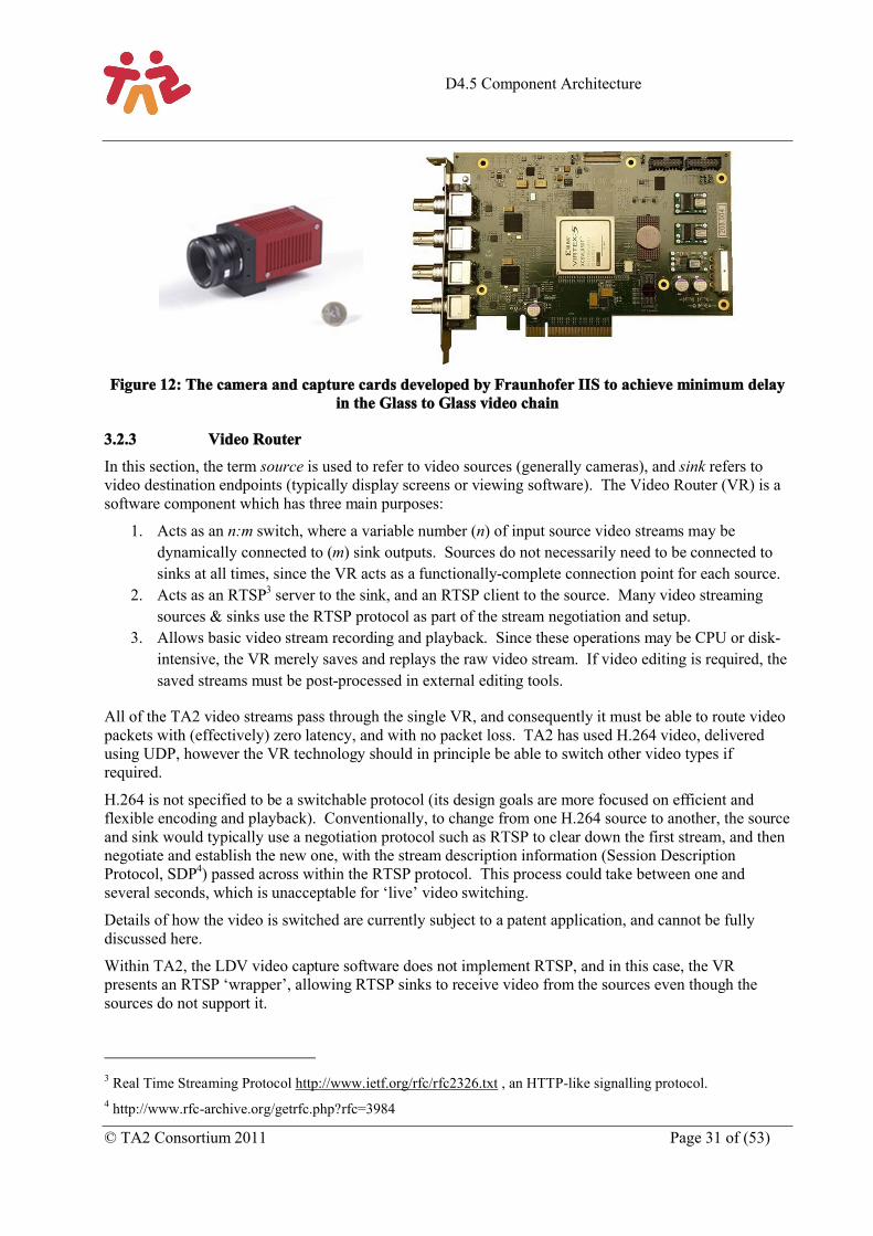
Figure 12: The camera and capture cards developed by Fraunhofer to achieve minimum delay in the Glass to Glass video chain ................................................................................................................................... 31
Figure 13: Real-time architecture of Analysis Engine ............................................................................... 33
Figure 14: Components of the Audio Communication Engine (ACE) ...................................................... 35
Figure 15: Basic block diagram of ACE-MCU allowing control of mixing process ................................ 36
Figure 16: Interaction of ACE and ACE-MCU with other components in the architecture. .................... 37
Figure 17: The uWand Interactive Pointer ................................................................................................. 41
Figure 18: The Connected Lobby showing the user’s contact list ............................................................. 41
Figure 19: The Connected Lobby within the TA2 architecture.................................................................. 42
Figure 20: Platform startup and basic application start ............................................................................. 44
Figure 21: Application teardown process.................................................................................................. 45
Figure 22: User login and self-view application. ....................................................................................... 46
Figure 23: Architecture of the orchestration engine................................................................................... 47
D4.5 Component Architecture
© TA2 Consortium 2011 Page 9 of (53)
1 IntroductionThe research project “Together Anywhere, Together Anytime” (TA2) seeks to understand how technology can “enhance relationships between groups of people who are separated in space and time”. This document describes a reference architecture derived from the work undertaken in the TA2 project.
TA2 has adopted a user centred design approach to answer this question and has defined a number of use cases and then designed and built the technology to embody each use case in a concept demonstrator. The concept demonstrators are described in a sister document D3.5 “Summary Report – Application Design and Implementation”.
The reference architecture is designed to support the real time communication use cases in the TA2 project. These involve rich communication (video and speech), together with a shared application which can be enjoyed by multiple people, at multiple ends, captured by multiple cameras. The architecture is capable of handling both real time and recorded streams of both audio and video and of compositing these inputs at each end point independently. In addition the architecture is able to intelligently decide how to compose the video output at each end based on analysis of the audio and video signals captured.
This document describes the architecture as a five layer model as shown in Figure 1 and goes on to describe some of the key design decisions taken in both the architecture and in the specification of components within each layer.
As part of the TA2 project we have assimilated understanding of group based social behaviour and also of computer mediated communications. This has helped us identify specific capabilities that, if enabled,might lead to experiences that would effectively enhance relationships between groups. Thesecapabilities include:
HD video: video transmitted at one of the accepted HD resolutions and with minimal delay, that provides either and both of peripheral awareness of people at each end and if necessary some indication of eye contact and the ability to transmit and interpret gesture and body language.
HD audio: audio transmitted using multichannel (at least stereo) full audio bandwidth (>24 kHz)in order to support relaxed hands free communications with sound presented through HiFi speakers and captured through microphones arrays.
Multiple HD cameras: in order to capture different views of each end. A shared focus: an activity which is common to all ends of the experience that provides a
common fun shared activity that aids in the building of social bonds between the participants. Orchestration: a means of selecting the camera view that provides the ‘best’ representation of
the remote ends to all parties involved in the shared experience.
In turn, these capabilities demand the additional capabilities:
Dynamic Screen Composition: This is the composition (following instructions from the orchestrator) on to one or more screens at each location, of combinations of real-time and file based media including the video streams from the cameras and local or centrally stored media such as elements of the game or shared photos or videos.
Automatic Audio video Analysis: Real time analysis of audio and video signals is used by the orchestrator to decide which of the possible combination of sources of media and video streams provides the “best” representation of the shared activity to each end.
D4.5 Component Architecture
Page 10 of (53) © TA2 Consortium 2011
We regard the following as the key design decisions that have enabled this architecture to achieve these functional goals. The reader is invited to look out for these in the text:
The wide scale adoption of XML-RPC as a transport protocol to link different components.
The use of SMIL to define the temporal and spatial layouts of the output screens.
The development of an adaptation to SMIL state to enable the dynamic adaptation of SMIL layouts.
The use of MPEG AAC Enhanced Low Delay (AAC-ELD) as a core component for facilitating HD audio communication.
The separation of client and network functions.
The logical separation of intelligent functionality into a single entity (the orchestrator) that controls the behaviour of other components.
The use of a single component to provide set up, session control and to act as a hub for communications between components.
The development of video router, a connection matrix between multiple sources and destinationswhich can replicate and switch streams all under external control. Additionally streams can be recorded and can either be reinserted into the output streams or post processed and made available off line.
The development of a highly capable SMIL driven composition engine which allows very rich visual compositions to be built from a range of different visual sources including real time video streams, recorded video, Flash files and still images.
D4.5 Component Architecture
© TA2 Consortium 2011 Page 11 of (53)
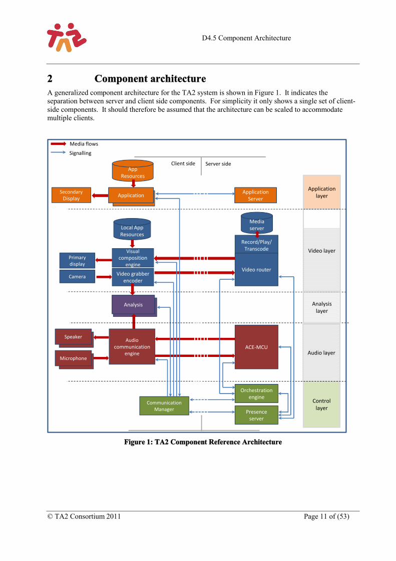
2 Component architectureA generalized component architecture for the TA2 system is shown in Figure 1. It indicates the separation between server and client side components. For simplicity it only shows a single set of client-side components. It should therefore be assumed that the architecture can be scaled to accommodate multiple clients.
Figure 1: TA2 Component Reference Architecture
Video layer
Audio layer
Control layer
Media server
Record/Play/Transcode
Video router
Visual composition
engine
Video grabber encoder
Analysis
Local App Resources
Primary display
Camera
ACE-MCUAudio
communicationengine
Speaker
Microphone
Orchestration engine
Presence server
Communication Manager
Client side Server side
Media flows
Signalling
Application layerApplication
App Resources
Application Server
Secondary Display
Analysis layer
D4.5 Component Architecture
Page 12 of (53) © TA2 Consortium 2011
The system can be considered as comprising five different layers:
The Application Layer contains components which could be proprietary to each application in which the TA2 system is being used. Each application may be different, but all will generally have local resources as input, as well as user interactions (not shown). In addition to application-specific resources presented on the Video Layer, the Application Layer may be responsible for a secondary screen as an output – for example a tablet PC or smartphone at each client location.
The Video Layer contains all the video processing components in the TA2 system. Its key inputs are video streams from one or more cameras at each client, as well as repositories of generic or application-specific resources (for example images, graphics, pre-recorded video, or interactive components such as Flash movies). Repositories can exist on the server side to provide input of pre-recorded video streams for multiple clients. The layer’s key output is the primary screen: usually the main domestic TV on which video compositions will be rendered.
The Audio Layer contains all the audio processing components in the TA2 system. Its key inputs are audio streams from multiple microphones at each client, and its key outputs are speakers through which sound is reproduced – usually in a domestic living room.
The Analysis layer contains a single module (Analysis) that takes both audio and video streams to generate cues relating to the activity taking place at each client location.
The Control Layer components are responsible for coordinating media processing components on all other layers, both by marshaling signals passed between them and, most importantly, by controlling their operation in order to create the optimal experience for participants at each client.
The following sub-sections summarise the capabilities of each component. Detailed descriptions will be given in section 3.
2.1 Client-side components
2.1.1 Applications
The TA2 system runs one or more applications locally. These are required to implement specific functionality, such as gameplay or media presentation, and generally provide the main mechanism for interaction between the TA2 system and its users. TA2 applications can also provide services which are common to multiple games or experiences (such as a buddy list).
Each Application implements an agreed interface with the Communication Manager. This is used to register the application’s existence and to communicate with the Orchestration Engine in order to co-ordinate both the game and the audiovisual experience.
Each Application may also implement a proprietary interface to a central Application Server in the network, for the purpose of coordinating state between multiple instances in different locations.
Applications include:
o Lobby: an application which registers and displays the presence of TA2 system participants on a secondary display, allowing other applications to be selected and people to be invited to participate in them.
o Space Alert: a co-operative board game adapted for the TA2 system, in which players on a stranded space ship must work together and solve challenges in order to make their way home to Earth. The Space Alert application is mostly presented in the primary display by means of Flash resources which are provided to the VCE. Its standalone application exists
D4.5 Component Architecture
© TA2 Consortium 2011 Page 13 of (53)
primarily to manage user interaction with the game via a secondary touch-screen and a proprietary RFID card reader.
o Storytelling: an application running on an iPad which allows reading a book together while being separated in space. Reading the book is synchronized, such that pages are turned at both sides. Sound effects and graphic are triggered on the iPad and appear on the video screen used for HD-Videoconferencing (i.e. the TV).
2.1.2 VCE: Visual Composition Engine
The VCE enables the composition of visual images at each TA2 location. It provides decoding and rendering to screen of real-time video at the lowest possible delay.
The VCE is capable of compositing the real-time video signals with pre-recorded media from a local repository. It can also incorporate other forms of content, such as Flash, from applications running locally. This enables a wide variety of visual presentations to be configured. It supports composition effects such as alpha blending for increased flexibility.
The VCE receives control and composition instructions from the Communication Manager. Composition information is expressed using the Synchronised Media Integration Language (SMIL), which has been extended to define how real-time and pre-recorded media can be composited spatially and temporally.
The VCE also provides an analogue stereo audio output (not shown in Figure 1) to the Audio Communication Engine (ACE) in order to feed through audio signals which accompany pre-recorded media from the local store.
2.1.3 Video Grabber/Encoder
The Video Grabber/Encoder is a high performance component designed to capture images from an HD video camera, encode them and transmit them to the Video Router with minimal added delay.
The Video Grabber captures digital or analogue video from a single camera using a hardware capture card. The SDI (Serial Digital Interface) standard is the preferred form of camera output, although signals can also be captured from low-cost HD webcam devices over USB. Optionally, a proprietary low-delay capture card can be used which enables encoding to begin before a complete frame has been buffered.
The Video Encoder is an H.264 encoder optimised for low-delay video transmission. It reduces delay by minimal buffering and uses Gradual Decoder Refresh (GDR) where possible to optimise packet transmission over contended networks.
A separate Video Grabber/Encoder is required for each HD video camera. Alternatively, lower cost IP cameras can be employed as the side cameras, if the environment can be set up such than an acceptable, matched HD image can be obtained.
Each Video Grabber/Encoder exposes a control interface to the Communication Manager for configuration of codec parameters and simple start/stop functions.
2.1.4 Analysis
The Analysis component processes live images from the Video Grabber/Encoder and audio samples from the ACE in order to generate cue information about the local environment of the TA2 System. One Analysis module is required for each camera to be analysed. In practice, it is usually sufficient that only the master (central) camera in a TA2 system will be analysed.
D4.5 Component Architecture
Page 14 of (53) © TA2 Consortium 2011
The Analysis component resides on the same platform as the Video Grabber/Decoder and thus receives images via a shared memory region on that platform. It receives audio samples from the ACE via a TCP socket connection.
Analysis consists of three sub-components: the Audio Cue Detection Engine (ACDE), the Visual Cue Detection Engine (VCDE) and the Unified Cue Detection Engine (UCDE). While the ACDE and VCDE are responsible for processing their respective feeds, the UCDE combines their output into a consistent set of cues.
The Analysis component has a bidirectional interface with the Communication Manager, which passes its cue information to the Orchestration Engine.
2.1.5 ACE: Audio Communication Engine
The ACE enables low-delay real-time audio communication between two or more locations. Specifically, it is responsible for capture, encoding, transmission, decoding and output.
The ACE captures audio from an array of between two and four microphones, passing these signals to the Analysis component (the master if more than one Analysis component is implemented).
The ACE encodes and transmits the audio signals as a two three distinct channels (left, right, and optionally centre).
As a core component it uses the MPEG AAC Enhanced Low Delay (AAC-ELD) audio codec – the same codec also employed in Apple Facetime.
The ACE performs echo control on the audio it captures and renders, and also allows external audio signals (not shown in Figure 1) to be mixed with real-time audio signals, via stereo analogue inputs on the ACE sound card. These are used e.g. for sound effect from the game application.
For transmission over IP, it incorporates Error Concealment (EC) and a sophisticated Jitter Buffer Management (JBM) to handle packet loss and delay variations. By adaptively changing the playout time using Time Scale Modification (TCM) it achieves an optimal trade-off between late-loss and buffering-delay.
The ACE exposes a control interface to the Communication Manager for configuration of codec parameters and the audio mixer.
2.1.6 Communication Manager
The CM is responsible for coordinating TA2 system components at a particular location and their interface with other locations and services in the network.
The CM has control interfaces with the ACE, VCE and Video Grabber/Encoders and these are used to exchange control information and composition instructions (including SMIL composition information). It has a bidirectional interface with the Analysis component(s) to co-ordinate the transmission of detected cue information to the Orchestration Engine.
All TA2 Applications running locally have a bidirectional interface into the CM, allowing them to register and synchronize the flow of the application with the process of orchestration, and receive cue information from the local Analysis component(s) if required.
Specifically, the CM includes two distinct modules:
o CM-LC (Local Control) – This is the primary CM module, a multi-threaded application which is responsible for all communications with local components within the TA2 system, and between local components and the Orchestration Engine in the network.
D4.5 Component Architecture
© TA2 Consortium 2011 Page 15 of (53)
o CM-SC (Session Control) – This module communicates with a network-based XMPP Presence Server to exchange presence and capability information relating to participants and locations with TA2 systems. It is also responsible for using standards-based protocols for establishing communications sessions between two or more TA2 systems.
2.2 Server-side components
2.2.1 Video Router and Stream Recorder/Player/Transcoder
The Video Router is a network-based video switching device which directs multiple video streams from a small number of TA2 clients to a selection of other clients in a manner which can be configured in real time.
The Video Router has a control interface from the Orchestration Engine, which provides it with real time instructions to copy one or more incoming streams to particular clients.
The Stream Recorder/Player/Transcoder is a network-based video recorder capable of recording multiple video streams to disk in real time, and playing selected streams back on demand. It works closely with the Video Router, which is responsible for the configuration of streams to be recorded or played back. It is also capable of performing offline transcoding of video streams such that they can be used by third party applications outside the TA2 system.
2.2.2 Audio Communication Engine Multipoint Control Unit (ACE-MCU)
The ACE-MCU (Multipoint Control Unit) is a centralised mixer for multiple audio streams from a small number of TA2 clients.
The ACE-MCU is responsible for decoding, mixing and re-encoding audio streams from each TA2 client.
In addition, it expose a control interface to the Communication Manager for the basic start/stop controls, plus the configuration of stereo panning and the volume control of audio streams. Using this interface it is, for example, possible to move a participant to the left side of the stereo image, or to completely mute one stream, e.g. to allow a secret conversation between client A and B while client C is not allowed to listen.
2.2.3 Orchestration Engine
The Orchestration Engine is a network-based component which is responsible for choosing at each moment the audio and video presentation to show at each TA2 client based on real-time physical and contextual information.
Physical information consists of the current position of each camera, person and screen in each room. Contextual information consists of high-level events produced by the Orchestration Engine’s Cue Lifter, informing of some new state of the system.
The Cue Lifter is a software component which lifts raw cues received from the Analysis component (e.g. person A started to talk) to higher-level states (e.g. person A and B are in a dialogue). Furthermore, application-related states (e.g. someone wins or loses the game being played) may be received from the applications at each client.
The output of the Orchestration Engine is a set of SMIL composition instructions, which are sent to each client and are then rendered by the local VCE.
The Orchestration Engine communicates with local components at each client through a control interface with each client’s Communication Manager.
D4.5 Component Architecture
Page 16 of (53) © TA2 Consortium 2011
2.2.4 Presence Server
The Presence Server is a standards-compliant XMPP server in the network which allows each TA2 client to register the presence of both users and system components, plus a limited amount of profile information. This information is then seamlessly provided to other TA2 clients.
TA2 server-side components also register with the Presence Server so that it is possible for each client to know when sufficient system resources are available to begin a session.
The Presence Server also acts as a multi-point SIP server, allowing multi-party sessions to be set up between multiple users at multiple TA2 endpoints. Once sessions are established, video and audio communication traffic is handled by the Video Router and ACE-MCU.
2.3 Communication between componentsStandardised interfaces and communication protocols are required for reliable communication between components in any complex system. The following subsections provide a brief summary of the main protocols used within the above architecture:
2.3.1 XML-RPC
XML-RPC is a stateless, (and in this implementation) blocking protocol running over HTTP, and is independent of the operating systems and architectures of the client and server computers. Method calls are able to pass both text and binary data in a reasonably efficient manner, and receive responses in a return payload. Method calls are subject to the same network limitations as other HTTP traffic: they are able to traverse NAT routing, but may be blocked by firewalls and (since they are generally sent in the clear), may be subject to packet snooping. Clients and servers must agree on the port being used, and firewalls must allow traffic on that port.
XML-RPC is used for communication between the Control Layer and components in all other layers. The multi-threaded Communication Manager acts as both a server and client for XML-RPC calls, and has the key role of relaying instructions from the Orchestration Engine to the relevant system components.
2.3.2 XMPP, Jingle and Muji
The Extensible Messaging and Presence Protocol (XMPP) is an open-standard protocol for instant messaging, presence information and contact list maintenance based on XML. It is widely used across the Internet and can be used to connect with both public and enterprise communications services. Jingle is an extension to XMPP which implements peer-to-peer session control for multimedia communication sessions. Jingle can be easily bridged with SIP, the widely-used signalling protocol which is distributed within domestic PCs, home gateways and personal devices. Muji (Multi-user Jingle) is proposed extension to XMPP to enable initiation and management of multi-party conferences within an XMPP multi-user chatroom.
In the TA2 system, the Presence Server is implemented using a standard XMPP server, and each Communication Manager implements an XMPP client which provides services to other components at the client end. These services include session initiation using Jingle and a simplified approach to Muji which makes use of multi-user chatrooms.
D4.5 Component Architecture
© TA2 Consortium 2011 Page 17 of (53)
3 Descriptions of the componentsThis section mirrors section 2 and provides more detailed descriptions of the components in each of the layers of the TA2 architecture shown in Figure 1.
3.1 Application layerThe applications that have been used as use cases, and for which specific applications are created in the application layer, are described in more detail in the accompanying public deliverable D3.5. This section is not designed to repeat information included in D3.5 but to illustrate how a range of real world implementations can be achieved in accordance with the generalised component architecture described in Figure 1. We highlight three real time use cases storytelling, music tuition and family game.
3.1.1 Storytelling
Grandparents love to keep an eye on grandchildren and tell them stories. Children love to hear their favourite stories over and over again. Grandparents normally have the time to take care of their grandchildren, but many times they cannot do so as the families are not living together. TA2 decided to target this intimate activity – storytelling – as one of its concept demonstrator. The TA2 system, seen as a medium for storytelling, will allow grandparents to tell stories in an engaging way to their grandchildren, and the other way around, when they are not living together. We try to reduce the spatial separation to a point where we approximate the feeling for both attendees as if they were together in the same room. At the same time we also try to enhance the overall storytelling experience by using multimedia extensions (sound, images, animation). Its value could be quite high as it could bring together two fragments of the family that in today’s world are becoming more and more divided.
The Storytelling demonstrators use a reduced number of components. It does not use orchestration nor analysis and has simple visual composition requirements and is designed to only connect two location so it has no need of a video router. This enables a much simpler implementation which was a requirement for the goal of putting the demonstrator into the homes of real users. A PC is used for HD-Videoconferencing and an iPad-app is used for the interactive storybook. The physical layout is shown in Figure 2.
D4.5 Component Architecture
Page 18 of (53) © TA2 Consortium 2011
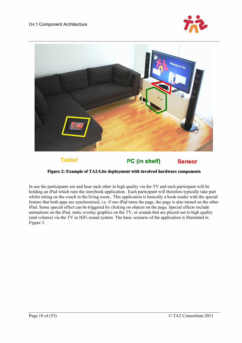
Figure 2: Example of TA2-Lite deployment with involved hardware components
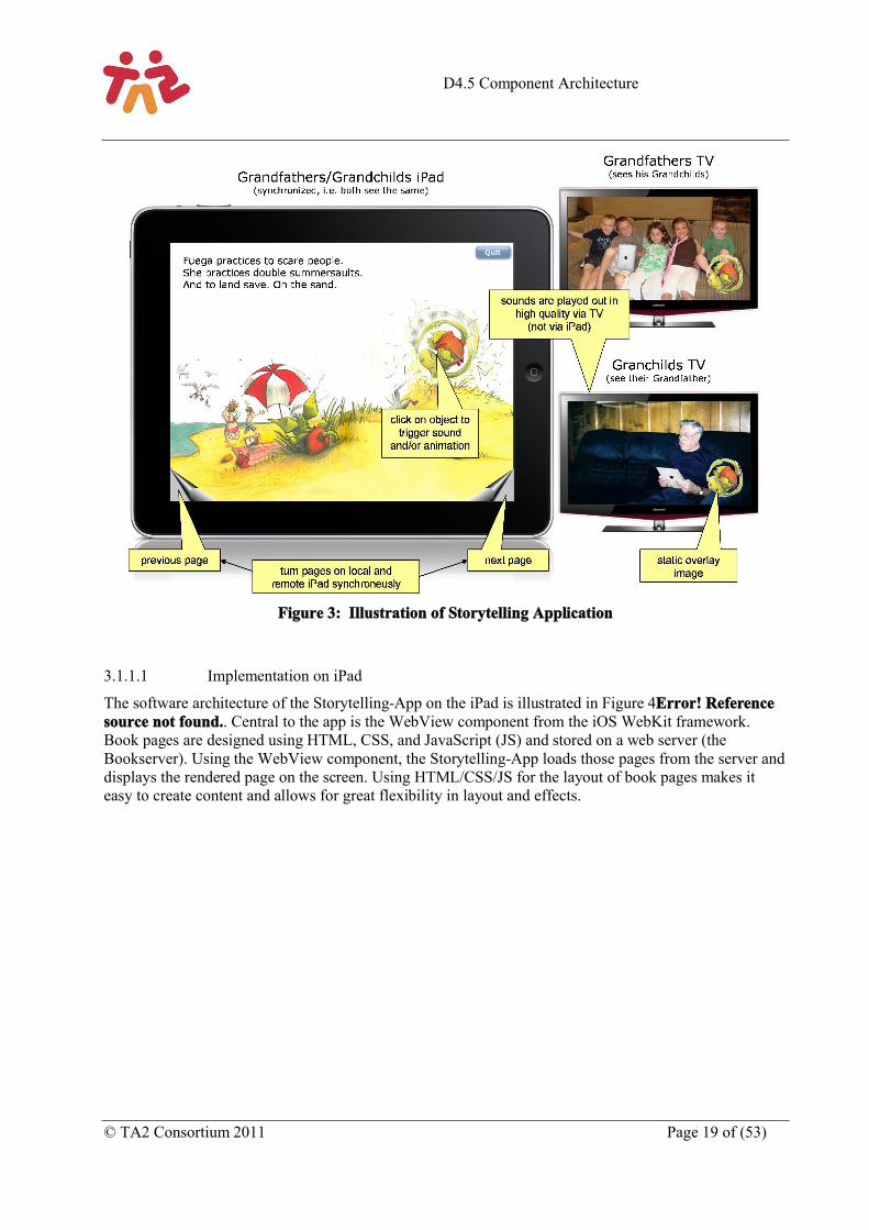
In use the participants see and hear each other in high quality via the TV and each participant will be holding an iPad which runs the storybook application. Each participant will therefore typically take part whilst sitting on the couch in the living room.. This application is basically a book reader with the special feature that both apps are synchronized, i.e. if one iPad turns the page, the page is also turned on the other iPad. Some special effect can be triggered by clicking on objects on the page. Special effects include animations on the iPad, static overlay graphics on the TV, or sounds that are played out in high quality (and volume) via the TV or HiFi sound system. The basic scenario of the application is illustrated inFigure 3.
D4.5 Component Architecture
© TA2 Consortium 2011 Page 19 of (53)
Figure 3: Illustration of Storytelling Application
3.1.1.1 Implementation on iPad
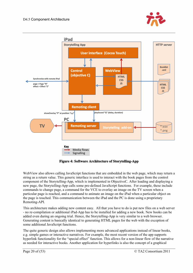
The software architecture of the Storytelling-App on the iPad is illustrated in Figure 4Error! Reference source not found.. Central to the app is the WebView component from the iOS WebKit framework. Book pages are designed using HTML, CSS, and JavaScript (JS) and stored on a web server (the Bookserver). Using the WebView component, the Storytelling-App loads those pages from the server and displays the rendered page on the screen. Using HTML/CSS/JS for the layout of book pages makes it easy to create content and allows for great flexibility in layout and effects.
D4.5 Component Architecture
Page 20 of (53) © TA2 Consortium 2011
Figure 4: Software Architecture of Storytelling-App
WebView also allows calling JavaScript functions that are embedded in the web page, which may return a string as a return value. This generic interface is used to interact with the book pages from the control component of the Storytelling-App, which is implemented in ObjectiveC. After loading and displaying a new page, the Storytelling-App calls some pre-defined JavaScript functions. For example, these include commands to change page, a command for the VCE to overlay an image on the TV screen when a particular page is reached, and a command to animate an image on the iPad when a particular object on the page is touched. This communication between the iPad and the PC is done using a proprietary Remoting-API.
This architecture makes adding new content easy. All that you have to do is put new files on a web server - no re-compilation or additional iPad-App has to be installed for adding a new book. New books can be added even during an ongoing trial. Hence, the Storytelling-App is very similar to a web browser. Generating content is basically identical to generating HTML pages for the web with the exception of some additional JavaScript functions.
The quite generic design also allows implementing more advanced applications instead of linear books, e.g. simple games or interactive narratives. For example, the most recent version of the app supports hyperlink functionality for the “special effect” function. This allows for a non-linear flow of the narrative as needed for interactive books. Another application for hyperlinks is also the concept of a graphical
HTTP serverStorytelling App
User interface (Cocoa Touch)
Control(objective C)
WebView
Remoting client
Storytelling add-onRemoting server
HTMLCSSJS
Booklist.xml
*.wav*.png
HTMLCSSJS
iPad
PCTV
Synchronise with remote iPad
page = Page “N”effect = Effect “Z”
showOverlay “P” at position “x,y” playSound “Q” (delay, duration)
Media flowsSignalling
Key
D4.5 Component Architecture
© TA2 Consortium 2011 Page 21 of (53)
“Book Shelf” for the selection of books. By touching the cover of a book, the user is forwarded to the start of the book following the embedded hyperlink. Under experimental study is also the possibility to drag objects on the page – synchronized in real-time on both iPads.
3.1.2 Music tuition
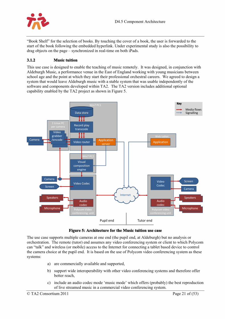
This use case is designed to enable the teaching of music remotely. It was designed, in conjunction with Aldeburgh Music, a performance venue in the East of England working with young musicians between school age and the point at which they start their professional orchestral careers. We agreed to design a system that would leave Aldeburgh music with a stable system that was usable independently of the software and components developed within TA2. The TA2 version includes additional optional capability enabled by the TA2 project as shown in Figure 5.
Figure 5: Architecture for the Music tuition use case
The use case supports multiple cameras at one end (the pupil end, at Aldeburgh) but no analysis or orchestration. The remote (tutor) end assumes any video conferencing system or client to which Polycom can “talk” and wireless (or mobile) access to the Internet for connecting a tablet based device to control the camera choice at the pupil end. It is based on the use of Polycom video conferencing system as these systems:
a) are commercially available and supported,
b) support wide interoperability with other video conferencing systems and therefore offer better reach,
c) include an audio codec mode ‘music mode’ which offers (probably) the best reproduction of live streamed music in a commercial video conferencing system.
1 Linux PCper camera
Win7 PC2
Win7 PC1
Web tablet
Polycom Video conferencing unit
Internet
Microphone
Audio codec
Speakers
Video Codec Screen
Microphone
Speakers
Visual composition
engine
Video router
Record play transcode
Data store
Camera
Camera
ApplicationApplication server
Polycom video conferencing unit
Audio codec
Video Codec
Camera
Video grabber/encode
Media flowsSignalling
Key
Screen
Pupil end Tutor end
D4.5 Component Architecture
Page 22 of (53) © TA2 Consortium 2011
The system is a hybrid system, and shows how components within the TA2 architecture can be integrated with commercial video conferencing systems to bring additional functionality. In this case the TA2 video components (the grabber, router and composition engine) enable multiple cameras (in this case cheap HD web cams) to be switched remotely by the tutor so they can observe different views of the student.
The audio layer is offered entirely by the Polycom system. Thus there is no audio communication engine and the codec used is not AAC-ELD but one of a choice of codecs negotiated by the Polycom system on call set up. The best codec choice is the Siren 22 codec in music mode (music mode switches off certain suppression filters designed to help in the clear transmission of voice) which offers the best reproduction of music.
The video layer is asymmetric. The pupil sees a straight-through view of the tutor only with the Polycom system providing the video layer. This design decision allowed the pupil-end to be reasonably unconstrained in terms of the equipment required. The only requirement was that the remote (pupil) end was able to connect to a Polycom system.
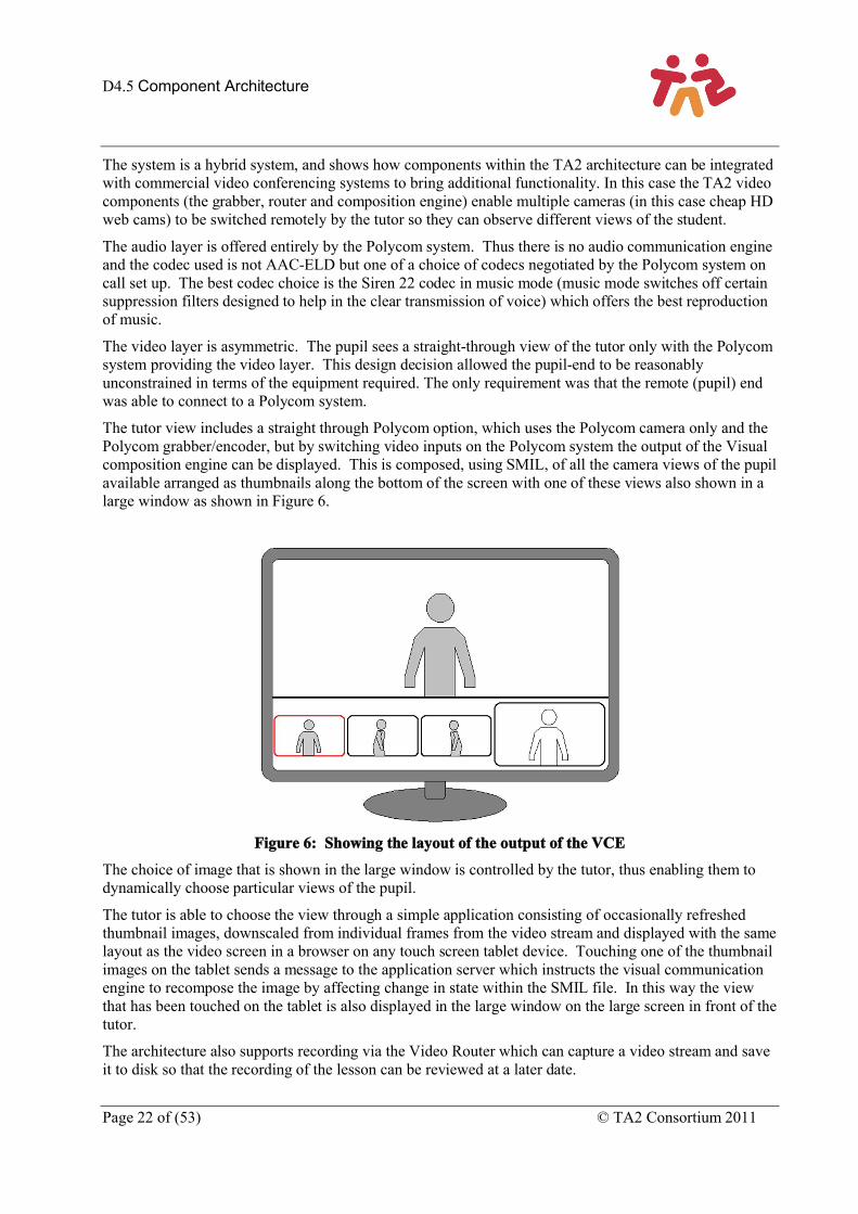
The tutor view includes a straight through Polycom option, which uses the Polycom camera only and the Polycom grabber/encoder, but by switching video inputs on the Polycom system the output of the Visual composition engine can be displayed. This is composed, using SMIL, of all the camera views of the pupil available arranged as thumbnails along the bottom of the screen with one of these views also shown in a large window as shown in Figure 6.
Figure 6: Showing the layout of the output of the VCE
The choice of image that is shown in the large window is controlled by the tutor, thus enabling them to dynamically choose particular views of the pupil.
The tutor is able to choose the view through a simple application consisting of occasionally refreshed thumbnail images, downscaled from individual frames from the video stream and displayed with the same layout as the video screen in a browser on any touch screen tablet device. Touching one of the thumbnail images on the tablet sends a message to the application server which instructs the visual communication engine to recompose the image by affecting change in state within the SMIL file. In this way the view that has been touched on the tablet is also displayed in the large window on the large screen in front of the tutor.
The architecture also supports recording via the Video Router which can capture a video stream and save it to disk so that the recording of the lesson can be reviewed at a later date.
D4.5 Component Architecture
© TA2 Consortium 2011 Page 23 of (53)
3.1.3 Family Game
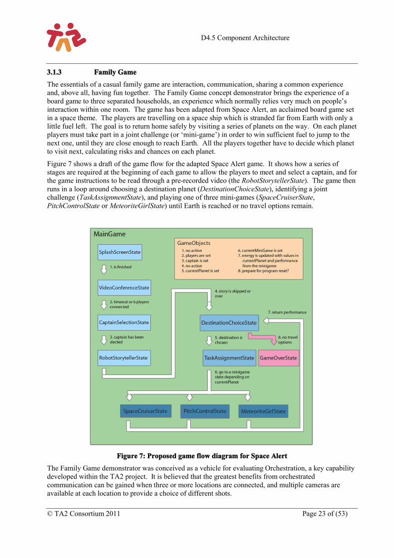
The essentials of a casual family game are interaction, communication, sharing a common experience and, above all, having fun together. The Family Game concept demonstrator brings the experience of a board game to three separated households, an experience which normally relies very much on people’s interaction within one room. The game has been adapted from Space Alert, an acclaimed board game set in a space theme. The players are travelling on a space ship which is stranded far from Earth with only a little fuel left. The goal is to return home safely by visiting a series of planets on the way. On each planet players must take part in a joint challenge (or ‘mini-game’) in order to win sufficient fuel to jump to the next one, until they are close enough to reach Earth. All the players together have to decide which planet to visit next, calculating risks and chances on each planet.
Figure 7 shows a draft of the game flow for the adapted Space Alert game. It shows how a series of stages are required at the beginning of each game to allow the players to meet and select a captain, and for the game instructions to be read through a pre-recorded video (the RobotStorytellerState). The game then runs in a loop around choosing a destination planet (DestinationChoiceState), identifying a joint challenge (TaskAssignmentState), and playing one of three mini-games (SpaceCruiserState, PitchControlState or MeteoriteGirlState) until Earth is reached or no travel options remain.
Figure 7: Proposed game flow diagram for Space Alert
The Family Game demonstrator was conceived as a vehicle for evaluating Orchestration, a key capability developed within the TA2 project. It is believed that the greatest benefits from orchestrated communication can be gained when three or more locations are connected, and multiple cameras are available at each location to provide a choice of different shots.
D4.5 Component Architecture
Page 24 of (53) © TA2 Consortium 2011
3.1.3.1 Family Game Implementation
Family Game makes use of a very similar technical architecture to that shown in Figure 1, and the components referenced below are as described in Section 3.
For the Application Layer, a central Application Server (the Wowza Media Server – www.wowza.com) is used to synchronise the state of the game between each endpoint, and to maintain global information such as energy levels.
The Space Alert application itself is mostly presented in the primary display: it consists of an Adobe Flash application which is loaded by the VCE as a local resource in the Video Layer and rendered in conjunction with the orchestrated live video streams from different locations. A proprietary SMIL file defining the screen layouts required for the different stages in the game has also been defined – and the same file is loaded by the VCE at each endpoint.
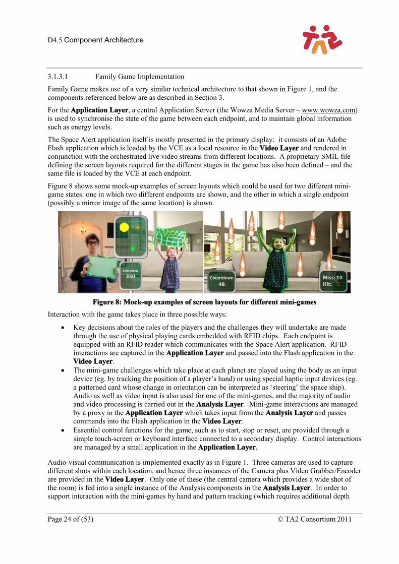
Figure 8 shows some mock-up examples of screen layouts which could be used for two different mini-game states: one in which two different endpoints are shown, and the other in which a single endpoint (possibly a mirror image of the same location) is shown.
Figure 8: Mock-up examples of screen layouts for different mini-games
Interaction with the game takes place in three possible ways:
Key decisions about the roles of the players and the challenges they will undertake are made through the use of physical playing cards embedded with RFID chips. Each endpoint is equipped with an RFID reader which communicates with the Space Alert application. RFID interactions are captured in the Application Layer and passed into the Flash application in the Video Layer.
The mini-game challenges which take place at each planet are played using the body as an input device (eg. by tracking the position of a player’s hand) or using special haptic input devices (eg. a patterned card whose change in orientation can be interpreted as ‘steering’ the space ship). Audio as well as video input is also used for one of the mini-games, and the majority of audio and video processing is carried out in the Analysis Layer. Mini-game interactions are managed by a proxy in the Application Layer which takes input from the Analysis Layer and passes commands into the Flash application in the Video Layer.
Essential control functions for the game, such as to start, stop or reset, are provided through a simple touch-screen or keyboard interface connected to a secondary display. Control interactions are managed by a small application in the Application Layer.
Audio-visual communication is implemented exactly as in Figure 1. Three cameras are used to capture different shots within each location, and hence three instances of the Camera plus Video Grabber/Encoder are provided in the Video Layer. Only one of these (the central camera which provides a wide shot of the room) is fed into a single instance of the Analysis components in the Analysis Layer. In order to support interaction with the mini-games by hand and pattern tracking (which requires additional depth
D4.5 Component Architecture
© TA2 Consortium 2011 Page 25 of (53)
information), a Microsoft Kinect sensor is connected to the Analysis components at each endpoint in addition to the conventional camera.
The Video Router receives incoming streams from each Video Grabber/Encoder at each endpoint, and is responsible for sending several of these streams to the VCE at each endpoint. Similarly, in the Audio Layer, an array of microphones is used to capture audio which is encoded and transmitted to the ACE-MCU via the Audio Communication Engine (ACE), as well as being provided to the Analysis Layer. Audio is mixed for each location in the ACE-MCU and re-transmitted back to the appropriate ACE, which then renders it through a 3-channel amplifier and speaker system.
In the Control Layer, the Orchestration Engine is responsible for managing the presentation of audio-visual communication in the game on two different levels:
The Dispatcher component within the Orchestration Engine maintains the state of the system as a whole, controlling the mapping between video sources and destinations in the Video Router, and controlling state information within the SMIL being rendered by each VCE. As the game moves from one state to the next, it signals the Orchestration Engine which ensures the correct video streams are available at each endpoint, and then instructs the VCE to change the composition as appropriate.
Within some states of the game, the Orchestration Engine is enabled for dynamic orchestration. Under these circumstances it will use real time cue information being passed from the Communication Manager at each endpoint to elicit camera selection decisions. While dynamic orchestration is enabled, the configuration of the Video Router and the SMIL state information at each VCE may be continuously adjusted by the Orchestration Engine.
Also as shown in Figure 1, the Communication Manager acts as the conduit for all XML-RPC messaging between components at each endpoint and components on the server side. Due to the complexity of the system in requiring multiple flows of real-time audio-visual data, the Communication Manager makes full use of the Presence Server to establish sessions with server-side components, as will be described later in this document.
To facilitate the logon process for multiple participants in a Family Game session, provision has been made for a Lobby application to run in the Application Layer in parallel with the Space Alert application components described above. The Lobby will also make use of the simple touch-screen or keyboard interface connected to the secondary display described above, and will hand off control of user interaction to the Space Alert applications when they start.
3.2 Video layerThe video layer includes the video grabber encoder, the visual composition engine and the video router. The video layer handles all the capture, encoding and transmission of visual content. It is designed to be highly capable - and can a manage a number of different types of visual content (live video, still images recorded video and Flash animations for example, and is able to composite these very effectively. It follows the instructions received from the control layer.
3.2.1 Visual Composition Engine (VCE)
The Visual Composition Engine is not only responsible for the video communication output chain but also for display of pre-recorded media: text, graphics, movies and even audio clips. The VCE should allow compositing of all these items in an aesthetic way. The VCE should be designed in such a way that it can provide the required dynamic composition goals, while still meeting the performance requirements. The VCE is a component that provides all the mechanisms for displaying video and media: it knows how to render these items. The policy, on the other hand (that determines when to render which media), is set
D4.5 Component Architecture
Page 26 of (53) © TA2 Consortium 2011
by the Orchestration and Activity components. Therefore, the VCE needs to provide an API of sufficiently high abstraction to these components to allow them to communicate their requirements. And there is a third party involved: the visual design of the activity is the realm of the graphics designer or user interface designer. This design is encoded in a (long-lived) document pertaining to the current activity that is used to drive the VCE.
3.2.1.1 Overall Description
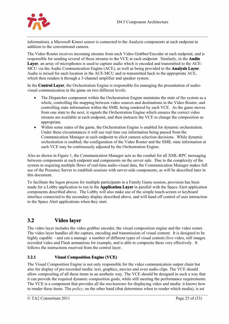
The VCE architecture is sketched in Figure 9. It has the capability for rendering and compositing a number of media sources, either real time or from file, to a display.
Figure 9: The VCE architecture
3.2.1.2 Scheduler Component
The control module of the VCE is a SMIL scheduler. The SMIL language1 not only provides visual composition but also has a rich set of temporal composition operators. SMIL has traditionally been used to allow multimedia presentations to be rendered at viewing time, as opposed to rendering at authoring time, as is the case for formats like QuickTime or MPEG-4. This feature enables authors to let presentations adapt to user interaction, bandwidth availability, and the environment. For playback of multimedia presentations, it has been shown that a declarative composition language like SMIL has advantages over static container formats. With the VCE we explore these advantages in the realm of multimedia videoconferencing and game playing, by allowing real-time modifications of running presentations.
Based on the timing instructions encoded in the SMIL document the scheduler instantiates rendering components for the various media items, at the right time and with the right parameters (screen position, colour settings, etc.). Live video display is handled by a specialized renderer, and treated identical to other media types. This enables the power of SMIL spatial and temporal composition to be used in a conferencing setting, without loss of generality: live video can partake in visual transitions and animations, and can be stopped and restarted on demand.
The use of SMIL enables a clean separation of composition mechanism and policy, thereby isolating the orchestration component from low-level timing and rendering issues: orchestration can schedule
1 SMIL 3.0 specification can be found at http://www.w3.org/TR/SMIL3/
SMIL scheduler
XMLRPC handler
SMIL state
Media renderer
SMIL document
store
RTP receiver(s)
CompositionDisplay
Local media
store(s)
D4.5 Component Architecture
© TA2 Consortium 2011 Page 27 of (53)
compositions to happen in the future without having to worry about real-time issues. In addition, SMIL Animation and Transitions provide mechanisms for implementing “eye candy” aesthetics in a relatively easy way. The composition engine is alpha-aware, hence partially transparent media and non-rectangular media are supported.
For the SMIL scheduler, composition engine, media renderers and support components such as XML parser we have used the open source Ambulant SMIL player2 as our basis. Ambulant is multithreaded, with locking at a level that allows us to make use of multiple cores in the renderers. It is also easily extended with the special-purpose live-video renderer needed for TA2.
3.2.1.3 Interface Exported to other TA2 Components
To allow interaction between the SMIL presentation and the external components the VCE uses an XMLRPC interface and SMIL State (a feature introduced in SMIL 3.0). Traditionally, the adaptations of which a SMIL presentation was capable had to be determined at authoring time, but SMIL State introduces a mechanism whereby external agents can change and add media items, and rendering parameters at rendering time. Values in the SMIL store can be used to control parameters in the presentation – to enforce the policies on video composition dictated by the orchestration engine. Moreover, changing a value in the data store can raise an event that can be used as a trigger to start or stop media rendering. Value changes are propagated immediately similar to the way a spreadsheet works. SMIL State is somewhat analogous to how DOM access allows changes to an HTML document at display time (albeit through a completely different mechanism).
SMIL State defines an interaction mechanism from the document point-of-view, but its model for communicating with external agents does not match very well with the TA2 requirements. Therefore we have a small XMLRPC server that listens for incoming commands, and modifies variables in the SMIL State data store. The new value is then propagated to the renderer component. The API exported by the XMLRPC server is tailored to the needs of the Orchestration and the game components, implementing the mechanisms to enable its policy decisions.
In particular, the current real-time composition-based functionality provided by the VCE include:
CutToCamera: to switch between one of the incoming video streams for better conveying social communication between locations
CropDisplayedVideo: to crop the received video for better framing a person, an action, or a communication pattern (e.g., a conversation in the room)
PlayOptionalMedia: to synchronize auxiliary graphics (e.g., images, text, other videos) for integrating the game play. For example by providing status related to the game on the television screen.
3.2.1.4 Video Output Component
Live video output merits special attention because it is the most critical when it comes to performance. Video output is received by an RTP receiver thread running as a DirectShow input filter and H.264-decoded. From this point there are two options, to be decided by the designer of the TA2 activity (i.e. the VCE can handle these options sequentially, and even simultaneously).
One option is to use direct rendering. The video frames are displayed on the screen directly, bypassing the composition redraw code. The position and size are controlled by the composition code, however. This method of display has the disadvantage that displaying other media items on top of the video is no longer possible, but it results in lower video delay.
2 http://www.ambulantplayer.org
D4.5 Component Architecture
Page 28 of (53) © TA2 Consortium 2011
The other option is to use composited rendering. This incurs a slight performance penalty, in the form of higher latency, but has the advantage that the visual designer has more freedom: static media items can be composited on top of video, and video can partake in visual transitions such as fades and wipes.
Video feeds to the VCEs are initially set up using RTSP: the video router component has a small RTSP server and the VCE a client. Because the live video components are treated just as any other media renderer there are no architectural limitations on the number of simultaneous incoming video feeds: the available hardware is the only factor determining how many video feeds can be displayed simultaneously. Video feeds can also be decoded without display, in a sort of standby mode. This may seem like a waste of resources, but it has one great advantage: if the orchestrator decides to switch the current displayed video to a stream that is in standby mode this switch can happen instantaneous, because the new video data has already been received and decoded. If the stream to be switched to is not in standby mode such a switch would take at least a few hundred milliseconds. And that number could get much higher (up to 8 seconds) in the case of aggressively optimized H.264 streams, as we are using in TA2.
3.2.1.5 Flash Component
Some TA2 activities will use a secondary screen to interact with the user, but some may be designed to use the primary screen. For these activities (read: games) there needs to be a way to have tighter realtime control over the screen output than is possible through XMLRPC calls (which can take in the order of 10 milliseconds). For this, the VCE includes a renderer that can play back Adobe Flash presentations. The design is very similar as for the live video renderer: the Flash renderer is started from the SMIL presentation but operates largely autonomous after that. Flash output graphics are rendered by the compositing renderer, and hence it is possible to have Flash rendered on top of live video, or vice versa. All with (partial) transparency, animations and transitions supported.
3.2.1.6 Role of the VCE in a TA2 Application
The SMIL document models the videoconferencing communication (real-time transmission of the video) and the current activity (the game), and has been created by the designer of the activity. This ensures that the “look and feel” of the videoconferencing matches that of the game, and that the interaction points between VCE and other components such as orchestration are well-defined. Upon start of the activity, the VCE is instructed (through an XMLRPC call) to open the SMIL document belonging to the activity. The scheduler creates a time graph based on the SMIL document, and then interprets this time graph. Whenever a media item has to be rendered, the scheduler determines which renderer is appropriate for the media item and creates it. From this point on, the renderer is semi-autonomous, which makes it relatively easy to ensure the parallelism needed to ensure good video and Flash performance. As the activity proceeds, other components such as Orchestration will issue commands to the XMLRPC server, which will implement them through SMIL State. Eventually the TA2 users will get fed up and return to the Lobby. From the VCE point of view, this is simply another activity: it will receive an XMLRPC request to open a new SMIL document and everything starts all over.
Using SMIL for our visual input and output ensures we have a good basis for specifying (and implementing) our synchronization requirements, and with SMIL State we have a mechanism that enables interaction between the SMIL scheduler, renderers and composition on the one hand and the remaining TA2 components on the other hand.
3.2.2 Video Grabber/Encoder
The Video Grabber/Encoder captures and encodes the video signal prior to sending over the network to the remote locations. Its job is to provide fast and efficient encoding of the image. There is a balance to be drawn here as the most efficient coding (that which requires the fewest bits to transmit a picture of a given quality) is not the fastest way of performing encoding. In this work in anticipation of broader bandwidth connections where bandwidth budget is not really a key issue, we have chosen to focus on
D4.5 Component Architecture
© TA2 Consortium 2011 Page 29 of (53)
optimising the speed of the encoding. End-to-end delay has a significant effect on real time communications; we are all familiar with the stilted conversations between newscaster and reporter over a satellite link and also perhaps with the occasional poor telephone link when dialling internationally. In these instances the end to end delay is typically several hundred milliseconds and it makes natural communications very difficult.
The International Telecommunications Union (recommendation G114) advises that:
“For non-speech applications such as interactive data or video, there are no agreed-upon assessment tools like the E-model, so the effects of delay on such applications must be carefully monitored. Although a few applications may be slightly affected by end-to-end (i.e., "mouth-to-ear" in the case of speech) delays of less than 150 ms, if delays can be kept below this figure, most applications, both speech and non-speech, will experience essentially transparent interactivity.”
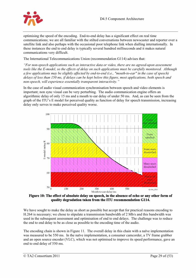
In the case of audio visual communication synchronisation between speech and video elements is important; non sync visual can be very perturbing. The audio communication engine offers an algorithmic delay of only 15 ms and a mouth to ear delay of under 50 ms. And, as can be seen from the graph of the ITU’s E model for perceived quality as function of delay for speech transmission, increasing delay only serves to make perceived quality worse.
Figure 10: The effect of absolute delay on speech, in the absence of echo or any other form of quality degradation taken from the ITU recommendation G114.
We have sought to make the delay as short as possible but accept that for practical reasons encoding to H.264 is necessary; we chose to stipulate a transmission bandwidth of 2 Mb/s and this bandwidth was used in the subsequent assessment and optimisation of end to end delays. The challenge was to reduce the end to end delay to be as close as possible to the encoding time of the audio.
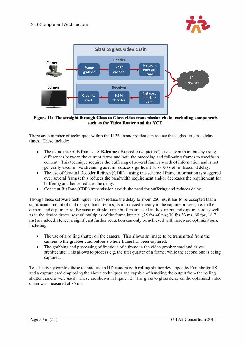
The encoding chain is shown in Figure 11. The overall delay in this chain with a naïve implementation was measured to be 550 ms. In the naïve implementation, a consumer camcorder, a TV frame grabber and an open source encoder (VLC), which was not optimised to improve its speed performance, gave an end to end delay of 550 ms.
D4.5 Component Architecture
Page 30 of (53) © TA2 Consortium 2011
Figure 11: The straight through Glass to Glass video transmission chain, excluding components such as the Video Router and the VCE.
There are a number of techniques within the H.264 standard that can reduce these glass to glass delay times. These include:
The avoidance of B frames. A B-frame ('Bi-predictive picture') saves even more bits by using differences between the current frame and both the preceding and following frames to specify its content. This technique requires the buffering of several frames worth of information and is not generally used in live streaming as it introduces significant 10 s-100 s of millisecond delay.
The use of Gradual Decoder Refresh (GDR) – using this scheme I frame information is staggered over several frames; this reduces the bandwidth requirement and/or decreases the requirement for buffering and hence reduces the delay.
Constant Bit Rate (CBR) transmission avoids the need for buffering and reduces delay.
Though these software techniques help to reduce the delay to about 260 ms, it has to be accepted that a significant amount of that delay (about 160 ms) is introduced already in the capture process, i.e. in the camera and capture card. Because multiple frame buffers are used in the camera and capture card as well as in the device driver, several multiples of the frame interval (25 fps 40 ms; 30 fps 33 ms, 60 fps, 16.7ms) are added. Hence, a significant further reduction can only be achieved with hardware optimizations, including
The use of a rolling shutter on the camera. This allows an image to be transmitted from the camera to the grabber card before a whole frame has been captured.
The grabbing and processing of fractions of a frame in the video grabber card and driver architecture. This allows to process e.g. the first quarter of a frame, while the second one is being captured.
To effectively employ these techniques an HD camera with rolling shutter developed by Fraunhofer IIS and a capture card employing the above techniques and capable of handling the output from the rolling shutter camera were used. These are shown in Figure 12. The glass to glass delay on the optimised video chain was measured at 85 ms.
D4.5 Component Architecture
© TA2 Consortium 2011 Page 31 of (53)
Figure 12: The camera and capture cards developed by Fraunhofer IIS to achieve minimum delay in the Glass to Glass video chain
3.2.3 Video Router
In this section, the term source is used to refer to video sources (generally cameras), and sink refers to video destination endpoints (typically display screens or viewing software). The Video Router (VR) is a software component which has three main purposes:
1. Acts as an n:m switch, where a variable number (n) of input source video streams may be dynamically connected to (m) sink outputs. Sources do not necessarily need to be connected to sinks at all times, since the VR acts as a functionally-complete connection point for each source.
2. Acts as an RTSP3 server to the sink, and an RTSP client to the source. Many video streaming sources & sinks use the RTSP protocol as part of the stream negotiation and setup.
3. Allows basic video stream recording and playback. Since these operations may be CPU or disk-intensive, the VR merely saves and replays the raw video stream. If video editing is required, the saved streams must be post-processed in external editing tools.
All of the TA2 video streams pass through the single VR, and consequently it must be able to route video packets with (effectively) zero latency, and with no packet loss. TA2 has used H.264 video, delivered using UDP, however the VR technology should in principle be able to switch other video types if required.
H.264 is not specified to be a switchable protocol (its design goals are more focused on efficient and flexible encoding and playback). Conventionally, to change from one H.264 source to another, the source and sink would typically use a negotiation protocol such as RTSP to clear down the first stream, and then negotiate and establish the new one, with the stream description information (Session Description Protocol, SDP4) passed across within the RTSP protocol. This process could take between one and several seconds, which is unacceptable for ‘live’ video switching.
Details of how the video is switched are currently subject to a patent application, and cannot be fully discussed here.
Within TA2, the LDV video capture software does not implement RTSP, and in this case, the VR presents an RTSP ‘wrapper’, allowing RTSP sinks to receive video from the sources even though the sources do not support it.
3 Real Time Streaming Protocol http://www.ietf.org/rfc/rfc2326.txt , an HTTP-like signalling protocol.4 http://www.rfc-archive.org/getrfc.php?rfc=3984
D4.5 Component Architecture
Page 32 of (53) © TA2 Consortium 2011
External control of the VR is via wrapper programming interface. Control commands are sent from other TA2 components, and comprise three groups:
1. Create and connect sources and sinks. Most of the camera sources used in TA2 do not support RTSP, and therefore when started they will stream their RTP video data to the VR regardless of whether the VR wishes them to or not. However in order for the VR to be able to route the feeds from those cameras, the VR must be instructed to create a source endpoint.
2. Connect or switch between various input and output endpoints.3. Ancillary functions: record and playback streams, and enumerate the connection lists.
The recording/playback interface allows individual streams to be serialised to disk and played back. Separate external tools have been developed to convert the serialised recordings into viewable and editable video files, although this is an offline process that cannot be performed in real time.
3.3 Analysis layerThe Analysis Engine architecture is built around several modules (as illustrated in Figure 13) comprising a face detector, a multiple face tracker, multiple person identification, head pose and visual focus of attention estimation, an audio real-time framework with spatial localisation, a large vocabulary continuous speech recognizer and keyword spotter, depth estimation, pointing and wiping detectors, pattern detector and tracker, multimodal association and fusion5. The system is designed to be used in open, unconstrained environments to allow multiple people to enter, interact and leave the observable world with no constraints.
5 The operation of these modules is described in a number of articles (Danil Korchagin P. M., 2011) (Danil Korchagin P. N., 2010) (Korchagin, 2011) (Odobez C. S.-M., 2011) (Odobez S. D.-M., 2011) (Stefan Duffner, 2011)
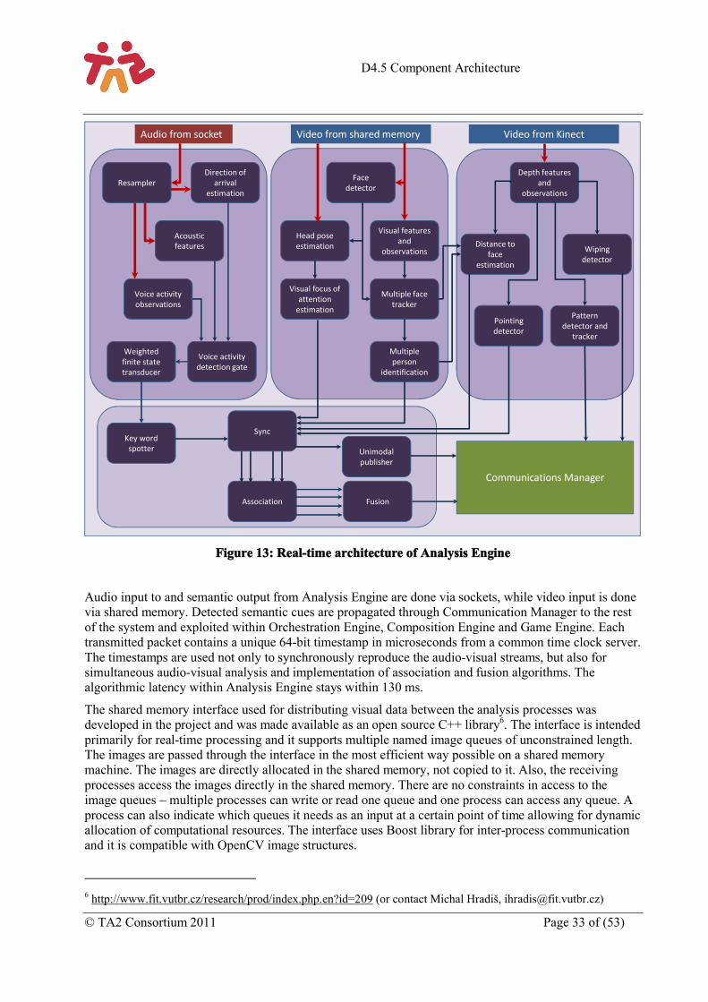
D4.5 Component Architecture
© TA2 Consortium 2011 Page 33 of (53)
Figure 13: Real-time architecture of Analysis Engine
Audio input to and semantic output from Analysis Engine are done via sockets, while video input is done via shared memory. Detected semantic cues are propagated through Communication Manager to the rest of the system and exploited within Orchestration Engine, Composition Engine and Game Engine. Each transmitted packet contains a unique 64-bit timestamp in microseconds from a common time clock server. The timestamps are used not only to synchronously reproduce the audio-visual streams, but also for simultaneous audio-visual analysis and implementation of association and fusion algorithms. The algorithmic latency within Analysis Engine stays within 130 ms.
The shared memory interface used for distributing visual data between the analysis processes was developed in the project and was made available as an open source C++ library6. The interface is intended primarily for real-time processing and it supports multiple named image queues of unconstrained length. The images are passed through the interface in the most efficient way possible on a shared memory machine. The images are directly allocated in the shared memory, not copied to it. Also, the receiving processes access the images directly in the shared memory. There are no constraints in access to the image queues – multiple processes can write or read one queue and one process can access any queue. A process can also indicate which queues it needs as an input at a certain point of time allowing for dynamic allocation of computational resources. The interface uses Boost library for inter-process communication and it is compatible with OpenCV image structures.
6 http://www.fit.vutbr.cz/research/prod/index.php.en?id=209 (or contact Michal Hradiš, [email protected])
ResamplerDirection of
arrivalestimation
Acoustic features
Voice activity observations
Weighted finite state transducer
Voice activity detection gate
Key word spotter
Sync
Unimodalpublisher
Association Fusion
Facedetector
Visual features and
observations
Head pose estimation
Visual focus of attention
estimation
Multiple face tracker
Multiple person
identification
Depth features and
observations
Wiping detector
Distance to face
estimation
Pointing detector
Pattern detector and
tracker
Video from KinectVideo from shared memoryAudio from socket
Communications Manager
D4.5 Component Architecture
Page 34 of (53) © TA2 Consortium 2011
In addition to the shared memory interface, we offer a pre-processing module which can be used to compute image transformations. This module supports scaling, cropping, colour-space conversions and other image processing operations. The transformations are defined by names of the image queues (sourceQueueName_! operation_arg1_arg2_!_operation_arg1_!_resultName). This pre-processing module allows common transformations to be computed only once and with high efficiency which is achieved by employing Intel Integrated Performance Primitives library.
In the Analysis Engine, the shared memory interface is used to distribute the full-resolution frontal camera view, depth map and colour image from Kinect and their transformations between more than 6 separate analysis processes. Both the shared memory interface and pre-processing module can be used on Windows and Linux.
3.4 Audio layerMost TA2 scenarios rely on live audio and video communication in order to create a feeling of togetherness between friends in remote locations. Audio is particularly important for natural communication, but still challenging to implement when full audio bandwidth, low delay, low bit rate, hands-free operation, and multichannel capability are considered. This section describes the audio transmission chain that is be used for the implementation of the TA2 concept demonstrators. It describes the internal components of the Audio Communication Engine (ACE) and the interfaces to external components in the TA2 architecture. More detailed information can be found in Deliverable D5.9 (Audio Transmission Chain – Second Release)
The ACE has been implemented within a distributed system on a dedicated PC and also in the somewhat simplified set up used for the Storytelling Application in an implementation where the ACE is one of many components running on single PC. In this case the ACE is implemented as a threaded module.
3.4.1 Components of the Audio Communication Engine
The functionality of the audio transmission chain is defined by the software modules within the ACE. As illustrated in Figure 14, these can be classified in three categories: codec, IP transport, and acoustic interface. The audio codec, implementing AAC-ELD can be seen as the core of the audio transmission chain. For the transmission of a stereo signal, it offers the full audio bandwidth (48 kHz sampling rate) at a bit rate of 128 kbit/s and 15 ms algorithmic delay. For transport over an IP network, the ACE offers RTP encapsulation and adaptive playout with Jitter Buffer Management (JBM) for minimal end-to-end delay. Besides the codec and IP transport, the acoustic interface is the third module of the ACE. It refers to the physical setup of microphones and loudspeakers as well as additional signal processing between those and the audio codec. One important functionality is the echo control (EC) as well as the processing of the microphone signals using Directional Audio Coding (DirAC). The ACE as used in the Family-Game demonstrator uses a 4-channel microphone array, which is processed into 3 audio channels (left, centre, right) for encoding, transmission, and reproduction. For Storytelling, the ACE uses stereo only.
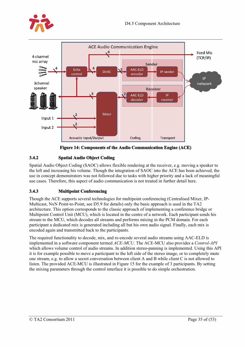
D4.5 Component Architecture
© TA2 Consortium 2011 Page 35 of (53)
Figure 14: Components of the Audio Communication Engine (ACE)
3.4.2 Spatial Audio Object Coding
Spatial Audio Object Coding (SAOC) allows flexible rendering at the receiver, e.g. moving a speaker to the left and increasing his volume. Though the integration of SAOC into the ACE has been achieved, the use in concept demonstrators was not followed due to tasks with higher priority and a lack of meaningful use cases. Therefore, this aspect of audio communication is not treated in further detail here.
3.4.3 Multipoint Conferencing
Though the ACE supports several technologies for multipoint conferencing (Centralised Mixer, IP-Multicast, NxN Point-to-Point, see D5.9 for details) only the basic approach is used in the TA2 architecture. This option corresponds to the classic approach of implementing a conference bridge or Multipoint Control Unit (MCU), which is located in the centre of a network. Each participant sends his stream to the MCU, which decodes all streams and performs mixing in the PCM domain. For each participant a dedicated mix is generated including all but his own audio signal. Finally, each mix is encoded again and transmitted back to the participants.
The required functionality to decode, mix, and re-encode several audio streams using AAC-ELD is implemented in a software component termed ACE-MCU. The ACE-MCU also provides a Control-APIwhich allows volume control of audio streams. In addition stereo-panning is implemented. Using this API it is for example possible to move a participant to the left side of the stereo image, or to completely mute one stream, e.g. to allow a secret conversation between client A and B while client C is not allowed to listen. The provided ACE-MCU is illustrated in Figure 15 for the example of 3 participants. By setting the mixing parameters through the control interface it is possible to do simple orchestration.
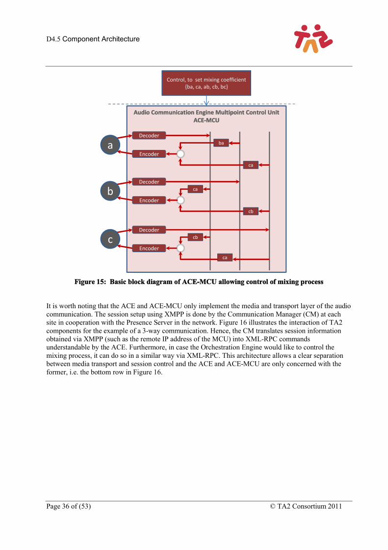
D4.5 Component Architecture
Page 36 of (53) © TA2 Consortium 2011
Figure 15: Basic block diagram of ACE-MCU allowing control of mixing process
It is worth noting that the ACE and ACE-MCU only implement the media and transport layer of the audio communication. The session setup using XMPP is done by the Communication Manager (CM) at each site in cooperation with the Presence Server in the network. Figure 16 illustrates the interaction of TA2 components for the example of a 3-way communication. Hence, the CM translates session information obtained via XMPP (such as the remote IP address of the MCU) into XML-RPC commands understandable by the ACE. Furthermore, in case the Orchestration Engine would like to control the mixing process, it can do so in a similar way via XML-RPC. This architecture allows a clear separation between media transport and session control and the ACE and ACE-MCU are only concerned with the former, i.e. the bottom row in Figure 16.
Audio Communication Engine Multipoint Control UnitACE-MCU
Control, to set mixing coefficient{ba, ca, ab, cb, bc}
Decoder
Encoder
Decoder
Encoder
Decoder
Encoder
ba
ca
ca
cb
cb
ca
a
b
c
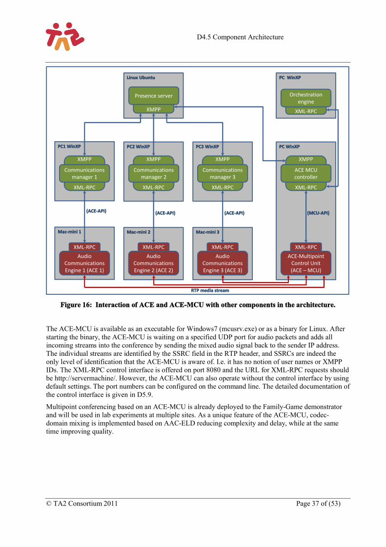
D4.5 Component Architecture
© TA2 Consortium 2011 Page 37 of (53)
Figure 16: Interaction of ACE and ACE-MCU with other components in the architecture.
The ACE-MCU is available as an executable for Windows7 (mcusrv.exe) or as a binary for Linux. After starting the binary, the ACE-MCU is waiting on a specified UDP port for audio packets and adds all incoming streams into the conference by sending the mixed audio signal back to the sender IP address. The individual streams are identified by the SSRC field in the RTP header, and SSRCs are indeed the only level of identification that the ACE-MCU is aware of. I.e. it has no notion of user names or XMPP IDs. The XML-RPC control interface is offered on port 8080 and the URL for XML-RPC requests should be http://servermachine/. However, the ACE-MCU can also operate without the control interface by using default settings. The port numbers can be configured on the command line. The detailed documentation of the control interface is given in D5.9.
Multipoint conferencing based on an ACE-MCU is already deployed to the Family-Game demonstrator and will be used in lab experiments at multiple sites. As a unique feature of the ACE-MCU, codec-domain mixing is implemented based on AAC-ELD reducing complexity and delay, while at the same time improving quality.
PC WinXP
PC WinXP
XML-RPC
Linux Ubuntu
XMPP
PC3 WinXPPC2 WinXPPC1 WinXP
XMPP
XML-RPC
XMPP
XML-RPC
XMPP
XML-RPC
XMPP
XML-RPC
Mac-mini 1 Mac-mini 2 Mac-mini 3
Presence server
Communications manager 1
Communications manager 2
Communications manager 3
ACE MCU controller
Audio Communications Engine 1 (ACE 1)
Audio Communications Engine 2 (ACE 2)
Audio Communications Engine 3 (ACE 3)
ACE-Multipoint Control Unit (ACE – MCU)
Orchestration engine
XML-RPCXML-RPCXML-RPCXML-RPC
(MCU-API)(ACE-API)(ACE-API) (ACE-API)
RTP media stream
D4.5 Component Architecture
Page 38 of (53) © TA2 Consortium 2011
3.4.4 Summary
The ACE is targeted towards the implementation of the TA2 concept demonstrators, in particular Family-Game and Storytelling. The provided functionality can be summarized as follows:
Spatial Audio Communication– 4-channel microphone array with – Multi-channel echo control– DirAC processing to 3-channel speaker setup (left, center, right)– Encoding of 3-channel AAC-ELD with 14 kHz audio bandwidth at 192 kbit/s– Low delay streaming with <50 ms end-to-end delay on LAN
Stereo Configuration for Storytelling– Stereo microphones using ORTF equivalence stereophony– Stereo AAC-ELD with 14 kHz audio bandwidth at 128 kbit/s– Custom build sensor housing for easy deployment in homes– Echo control and IP-streaming as above
C/C++ API– Two API levels, the core ACE library (CDuplex) and a demo application (CAceApplication)– Doxygen Documentation
Network API– Control of operation from remote host via LAN using XML-RPC– SDK with stub code for easy implementation
Audio IO– Forwarding of echo controlled microphone signals via TCP/IP (to Analysis-PC)– Reception of two analog input sources for sound effects (from VCE and Application-PC).
Echo controlled output after upmix to three channels. Support for setting additional delay and dynamic volume control Multipoint Conferencing
– Multipoint Control Unit (MCU) for ACE clients (ACE-MCU)– XML-RPC control interface for basic orchestration– Codec-domain mixing
Spatial Audio Object Coding (SAOC)– Interactive rendering of multiple objects (speakers) at low bit rate– Real time demonstrator for communication scenarios
The audio transmission chain, as made available to the TA2 project, provides a unique feature set and provides a competitive position compared to the state of the art. It is a significant step forward towards natural communication in the context of shared experiences with online applications. The fact that it is used by four TA2 partners (CWI, BT, ALU, GOLD) as part of the Family-Game demonstrator as well as by Interactive Institute as part of the Storytelling demonstrator for longitudinal in-situ studies, shows its usefulness and maturity. We therefore believe that the audio transmission chain as a technology component for the TA2 project has helped to “make communication and engagement easier among families and friends separated in space”.
D4.5 Component Architecture
© TA2 Consortium 2011 Page 39 of (53)
3.5 Control layerAs described in Section 2.1.6 the following functions are performed in the control layer:
The Control layer simplifies the flow of communications between different components. By having a single hub marshalling the communications the number of APIs required is reduced. (In a free-for-all system where all components could talk to each other the number of APIs would increase as the square of the number of components. In this case the number of APIs increases linearly with the number of components.
The Control Layer manages presence information and initiates communication between end points.
The Control Layer provides instructions (largely to the VCE) using inputs from analysis, that affects the way the mediated communication is presented by instruction selecting particular camera shots. This provides very clear separation of the decision making from the execution of the decisions. This has helped define a clear focus of development for the Orchestration Engine (which makes the decisions) and the Visual Composition Engine and the Video router which execute them.
These functions are controlled through the Communications Manager, the Presence Server and the Orchestration Engine respectively.
3.5.1 Communications manager
The Communication Manager (CM) communicates with local components within the TA2 system and manages data flows between them.
3.5.1.1 Pass-through XML-RPC method calls.
In the TA2 platform XML-RPC communications between the VCE, Analysis engine and the Orchestrator pass through the Communication Manager (CM). At present for most RPC calls this is facilitated in the CM as a two stage process, with the Abyss RPC server processing forwarding the message payload on to the destination as a tandem RPC call. This approach has the benefits that the CM - the only TA2 platform component with any location knowledge - can parse the message payload if necessary and append location or other unique platform data. This is done in all messages from the Analysis engine to the orchestrator – e.g. Analysis.PersonNbChange, Analysis.FacePosition etc.
The drawback to this approach is we are using XML-RPC as a blocking protocol, and thus the tandem call must be completed before the server can handle a further call. For most calls this does not represent any significant problem. However, some calls from the Analysis engine can be very frequent, and in order to prevent excessive blocking the forwarding call is passed to a separate thread via a queuing process to smooth out the peaks. Further developments of the CM are likely to extend this process to all XML-RPC communications.
3.5.1.2 The Local Controller
The local controller part of the Communications Manager is responsible for all aspects of control of the TA2 platform components. This includes platform startup, application startup, setting up audio and video connections with the ACE_MCU and video router. Note there is no need for the application itself do anything to set-up the interplatform communications. This is done by the CM as described below.
3.5.1.3 ‘Presence’ of TA2 system components
One of the features of the TA2 system philosophy is that the Ta2 platforms themselves, the Orchestrator, the video router and the ACE_MCU all have ‘presence’ in that they can log into the Presence Server.
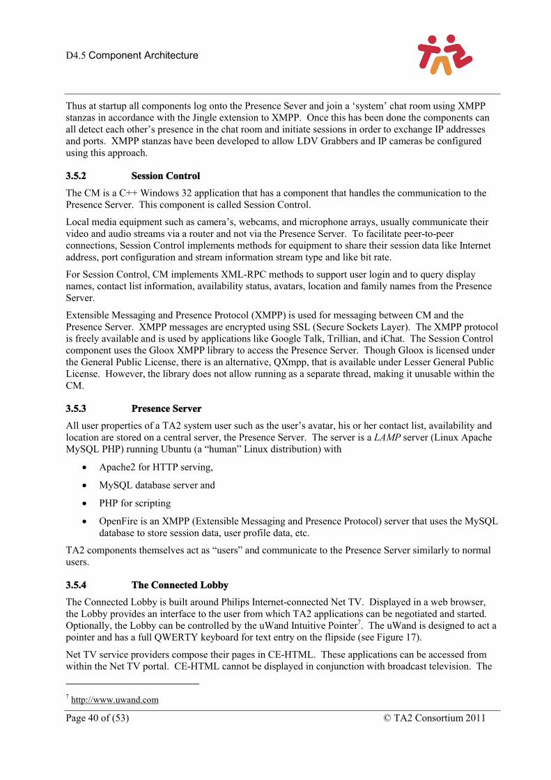
D4.5 Component Architecture
Page 40 of (53) © TA2 Consortium 2011
Thus at startup all components log onto the Presence Sever and join a ‘system’ chat room using XMPP stanzas in accordance with the Jingle extension to XMPP. Once this has been done the components can all detect each other’s presence in the chat room and initiate sessions in order to exchange IP addresses and ports. XMPP stanzas have been developed to allow LDV Grabbers and IP cameras be configured using this approach.
3.5.2 Session Control
The CM is a C++ Windows 32 application that has a component that handles the communication to the Presence Server. This component is called Session Control.
Local media equipment such as camera’s, webcams, and microphone arrays, usually communicate their video and audio streams via a router and not via the Presence Server. To facilitate peer-to-peer connections, Session Control implements methods for equipment to share their session data like Internet address, port configuration and stream information stream type and like bit rate.
For Session Control, CM implements XML-RPC methods to support user login and to query display names, contact list information, availability status, avatars, location and family names from the Presence Server.
Extensible Messaging and Presence Protocol (XMPP) is used for messaging between CM and the Presence Server. XMPP messages are encrypted using SSL (Secure Sockets Layer). The XMPP protocol is freely available and is used by applications like Google Talk, Trillian, and iChat. The Session Control component uses the Gloox XMPP library to access the Presence Server. Though Gloox is licensed under the General Public License, there is an alternative, QXmpp, that is available under Lesser General Public License. However, the library does not allow running as a separate thread, making it unusable within the CM.
3.5.3 Presence Server
All user properties of a TA2 system user such as the user’s avatar, his or her contact list, availability and location are stored on a central server, the Presence Server. The server is a LAMP server (Linux Apache MySQL PHP) running Ubuntu (a “human” Linux distribution) with
Apache2 for HTTP serving,
MySQL database server and
PHP for scripting
OpenFire is an XMPP (Extensible Messaging and Presence Protocol) server that uses the MySQL database to store session data, user profile data, etc.
TA2 components themselves act as “users” and communicate to the Presence Server similarly to normal users.
3.5.4 The Connected Lobby
The Connected Lobby is built around Philips Internet-connected Net TV. Displayed in a web browser, the Lobby provides an interface to the user from which TA2 applications can be negotiated and started. Optionally, the Lobby can be controlled by the uWand Intuitive Pointer7. The uWand is designed to act a pointer and has a full QWERTY keyboard for text entry on the flipside (see Figure 17).
Net TV service providers compose their pages in CE-HTML. These applications can be accessed from within the Net TV portal. CE-HTML cannot be displayed in conjunction with broadcast television. The
7 http://www.uwand.com
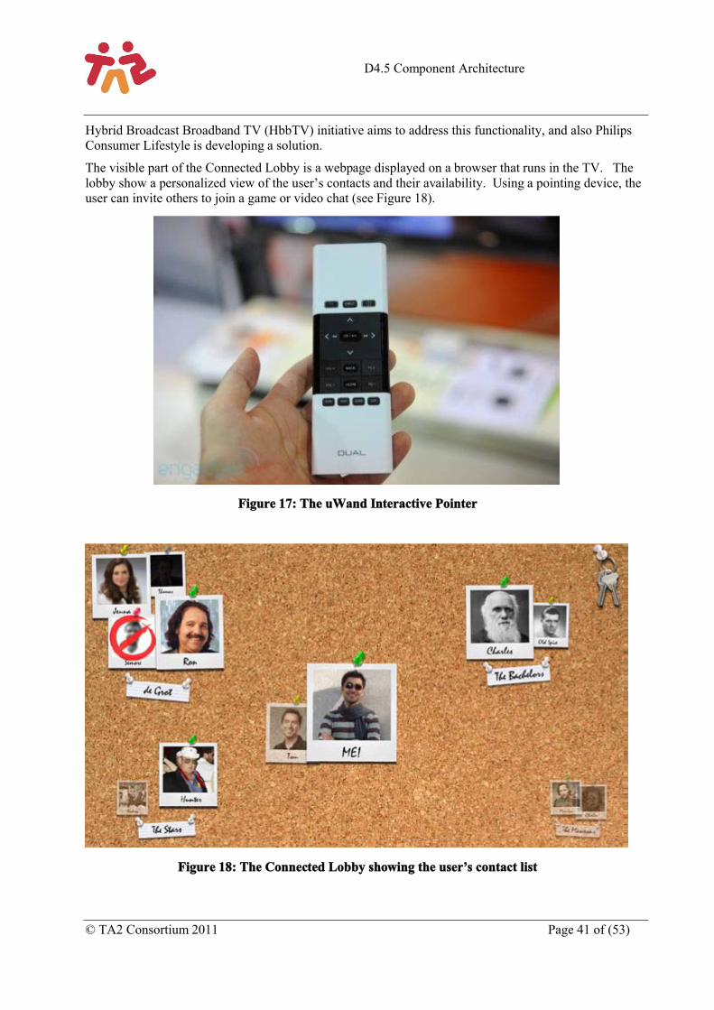
D4.5 Component Architecture
© TA2 Consortium 2011 Page 41 of (53)
Hybrid Broadcast Broadband TV (HbbTV) initiative aims to address this functionality, and also Philips Consumer Lifestyle is developing a solution.
The visible part of the Connected Lobby is a webpage displayed on a browser that runs in the TV. The lobby show a personalized view of the user’s contacts and their availability. Using a pointing device, the user can invite others to join a game or video chat (see Figure 18).
Figure 17: The uWand Interactive Pointer
Figure 18: The Connected Lobby showing the user’s contact list
D4.5 Component Architecture
Page 42 of (53) © TA2 Consortium 2011
Figure 19: The Connected Lobby within the TA2 architecture
The TV’s internal processor has limited computational power and therefore the communication to the presence server is taken over by the Communication Manager (CM). That also allows other applications to share presence information with the server. The lobby sends command to the CM using XML-RPC which the CM can process and pass on to the Presence Server. The Lobby itself is written in JavaScript, which is part of the HTML-CE standard
The Lobby can send high-level commands to the CM. The Session Control component of the CM takes care of the communication to the Presence Server. The Lobby calls are implemented as XML-RPC calls (an HTTP request with function names and arguments in XML). The Lobby has a JavaScript library that creates and parses XML-RPC commands.
JavaScript’s same-origin policy restricts the Lobby from performing calls to the CM and request information from the Lobby back-end server at the same time. Therefore, we use a reverse proxy server (WampServer8) that translates all Lobby request as if they were handles by the same server.
8 http://www.wampserver.com
IP Connected TV
Web server
Linux Ubuntu
XMPP
PC WinXP
XMPP
XML-RPC
Presence server
Communications manager
ConnectedLobby
XML-RPC
(Lobby API)
HTTP
Personal device
Web browser
ConnectedLobby
Web browser
ConnectedLobby
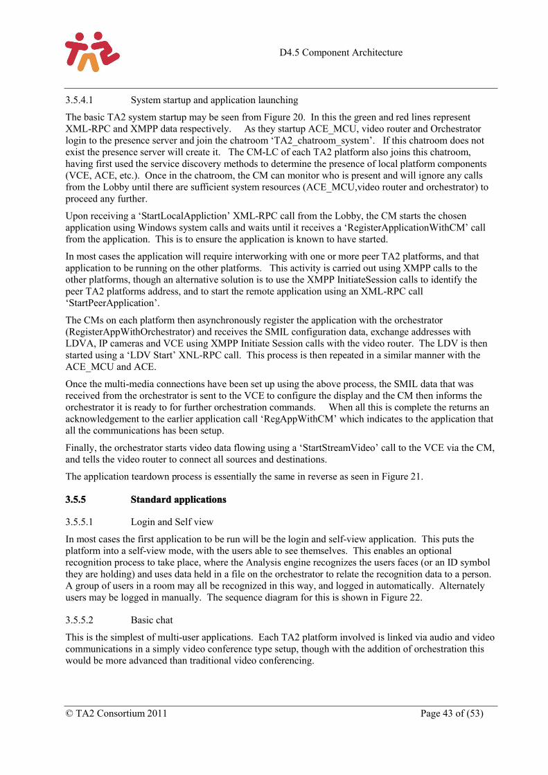
D4.5 Component Architecture
© TA2 Consortium 2011 Page 43 of (53)
3.5.4.1 System startup and application launching
The basic TA2 system startup may be seen from Figure 20. In this the green and red lines represent XML-RPC and XMPP data respectively. As they startup ACE_MCU, video router and Orchestrator login to the presence server and join the chatroom ‘TA2_chatroom_system’. If this chatroom does not exist the presence server will create it. The CM-LC of each TA2 platform also joins this chatroom, having first used the service discovery methods to determine the presence of local platform components (VCE, ACE, etc.). Once in the chatroom, the CM can monitor who is present and will ignore any calls from the Lobby until there are sufficient system resources (ACE_MCU,video router and orchestrator) to proceed any further.
Upon receiving a ‘StartLocalAppliction’ XML-RPC call from the Lobby, the CM starts the chosen application using Windows system calls and waits until it receives a ‘RegisterApplicationWithCM’ call from the application. This is to ensure the application is known to have started.
In most cases the application will require interworking with one or more peer TA2 platforms, and that application to be running on the other platforms. This activity is carried out using XMPP calls to the other platforms, though an alternative solution is to use the XMPP InitiateSession calls to identify the peer TA2 platforms address, and to start the remote application using an XML-RPC call ‘StartPeerApplication’.
The CMs on each platform then asynchronously register the application with the orchestrator (RegisterAppWithOrchestrator) and receives the SMIL configuration data, exchange addresses with LDVA, IP cameras and VCE using XMPP Initiate Session calls with the video router. The LDV is then started using a ‘LDV Start’ XNL-RPC call. This process is then repeated in a similar manner with the ACE_MCU and ACE.
Once the multi-media connections have been set up using the above process, the SMIL data that was received from the orchestrator is sent to the VCE to configure the display and the CM then informs the orchestrator it is ready to for further orchestration commands. When all this is complete the returns an acknowledgement to the earlier application call ‘RegAppWithCM’ which indicates to the application that all the communications has been setup.
Finally, the orchestrator starts video data flowing using a ‘StartStreamVideo’ call to the VCE via the CM, and tells the video router to connect all sources and destinations.
The application teardown process is essentially the same in reverse as seen in Figure 21.
3.5.5 Standard applications
3.5.5.1 Login and Self view
In most cases the first application to be run will be the login and self-view application. This puts the platform into a self-view mode, with the users able to see themselves. This enables an optional recognition process to take place, where the Analysis engine recognizes the users faces (or an ID symbol they are holding) and uses data held in a file on the orchestrator to relate the recognition data to a person. A group of users in a room may all be recognized in this way, and logged in automatically. Alternately users may be logged in manually. The sequence diagram for this is shown in Figure 22.
3.5.5.2 Basic chat
This is the simplest of multi-user applications. Each TA2 platform involved is linked via audio and video communications in a simply video conference type setup, though with the addition of orchestration this would be more advanced than traditional video conferencing.
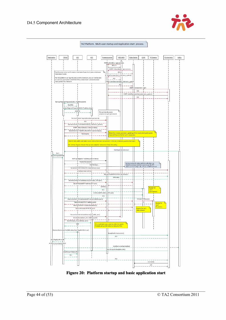
D4.5 Component Architecture
Page 44 of (53) © TA2 Consortium 2011
Figure 20: Platform startup and basic application start
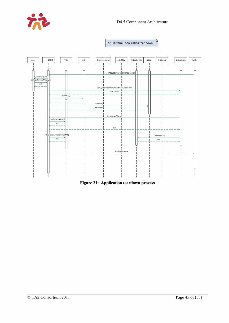
D4.5 Component Architecture
© TA2 Consortium 2011 Page 45 of (53)
Figure 21: Application teardown process
D4.5 Component Architecture
Page 46 of (53) © TA2 Consortium 2011
Figure 22: User login and self-view application.
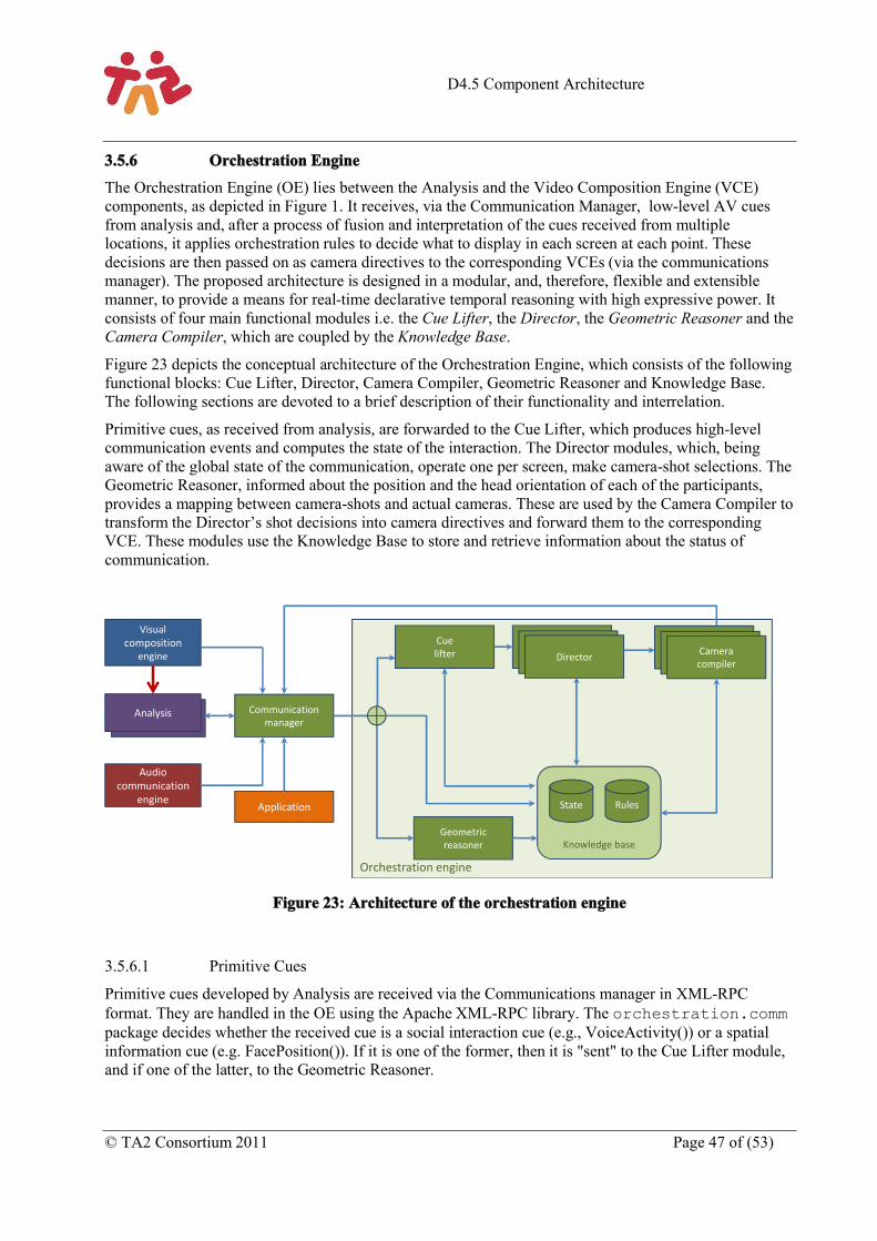
D4.5 Component Architecture
© TA2 Consortium 2011 Page 47 of (53)
3.5.6 Orchestration Engine
The Orchestration Engine (OE) lies between the Analysis and the Video Composition Engine (VCE) components, as depicted in Figure 1. It receives, via the Communication Manager, low-level AV cues from analysis and, after a process of fusion and interpretation of the cues received from multiple locations, it applies orchestration rules to decide what to display in each screen at each point. These decisions are then passed on as camera directives to the corresponding VCEs (via the communications manager). The proposed architecture is designed in a modular, and, therefore, flexible and extensible manner, to provide a means for real-time declarative temporal reasoning with high expressive power. It consists of four main functional modules i.e. the Cue Lifter, the Director, the Geometric Reasoner and the Camera Compiler, which are coupled by the Knowledge Base.
Figure 23 depicts the conceptual architecture of the Orchestration Engine, which consists of the following functional blocks: Cue Lifter, Director, Camera Compiler, Geometric Reasoner and Knowledge Base. The following sections are devoted to a brief description of their functionality and interrelation.
Primitive cues, as received from analysis, are forwarded to the Cue Lifter, which produces high-level communication events and computes the state of the interaction. The Director modules, which, being aware of the global state of the communication, operate one per screen, make camera-shot selections. The Geometric Reasoner, informed about the position and the head orientation of each of the participants, provides a mapping between camera-shots and actual cameras. These are used by the Camera Compiler to transform the Director’s shot decisions into camera directives and forward them to the corresponding VCE. These modules use the Knowledge Base to store and retrieve information about the status of communication.
Figure 23: Architecture of the orchestration engine
3.5.6.1 Primitive Cues
Primitive cues developed by Analysis are received via the Communications manager in XML-RPC format. They are handled in the OE using the Apache XML-RPC library. The orchestration.commpackage decides whether the received cue is a social interaction cue (e.g., VoiceActivity()) or a spatial information cue (e.g. FacePosition()). If it is one of the former, then it is "sent" to the Cue Lifter module, and if one of the latter, to the Geometric Reasoner.
Orchestration engine
Knowledge base
Analysis Communication manager
Cuelifter
Geometric reasoner
Communication Manager
Communication ManagerDirector
Communication Manager
Communication Manager
Cameracompiler
State Rules
Audio communication
engine
Visual composition
engine
Application
D4.5 Component Architecture
Page 48 of (53) © TA2 Consortium 2011
3.5.6.2 Cue Lifter
The Cue Lifter lifts primitive cues received from AV Analysis to a more abstract, higher semantic level. This module generates semantically richer events (i.e., “turn-shift”, “cross-talk”, “pattern of short-turn-taking” and “relevancy marker”) based on definitions expressed declaratively as JBoss Drools rules. JBoss Drools is a complex event processing (CEP) framework, which is put to use in our system to fuse cue event streams arriving out-of-order from multiple locations in order to compute a global state of interaction. It tracks the social interaction of all rooms by detecting e.g. “Who is currently the active person?” or “Is there a cross talking situation?”.
3.5.6.3 Director
The application of the editing rules i.e., the ones that make shot decisions for each particular screen is a task undertaken by the Director component. In the proposed architecture (see Figure 23) there are multiple Director instances running in parallel; there is one Director instance operating per location. However, Directors do not operate in isolation; they receive high-level events from the Cue Lifter originating from all the locations and query the Knowledge Base to ensure their awareness of the current global state of the interaction before they apply rules. The input is global, but the conclusions are local. We chose to model the problem this way because it resembles the way human editors operate. The Director component is also implemented on the JBoss Drools CEP framework.
3.5.6.4 Geometric Reasoner
Decisions about shots need to be compiled into camera directives. The Geometric Reasoner carries out this task. The Geometric Reasoner continuously computes the degree up to which each camera supports each one of the possible types of shots for each person. Calculations are based on information regarding the overall setup, angles and characteristics of cameras combined with the position and head orientation of each person.
The Geometric Reasoner outputs (i) an event stream that notifies the Directors when a shot is or is not currently attainable and (ii) a mapping for all the possible shots within a location to corresponding camera directives, together with associated confidence factors. The Geometric Reasoner is taking the participants' head orientation into account to determine how well a shot is realized by a certain camera. The Geometric Reasoner is implemented in plain old Java.
3.5.6.5 Camera Compiler
Whenever a shot decision is made, the mapping is read from the Knowledge Base by the associated Camera Compiler to translate the shot into an actual camera decision.
This module receives the shot selections for each screen/Location from the corresponding Director and compiles them down to camera selections by using shot-to-camera mappings calculated by the Geometric Reasoner. It outputs camera selection decisions for each of the corresponding screen, which are passed to the CM to instruct the VCE.
3.5.6.6 Knowledge Base
The Knowledge Base is shared between all the reasoning modules (as depicted in Figure 23). It manages both global and location-specific states and offers an interface for efficient manipulation and querying. It is partly built into the JBoss Drools framework (for the Cue Lifter and Director modules) and partly plain old Java based (for the Geometric Reasoner).
D4.5 Component Architecture
© TA2 Consortium 2011 Page 49 of (53)
3.5.6.7 Camera Directives
The camera directives are sent to the VCE’s, via the CM, in XML-RPC format. As for the primitive cues, all the XML-RPC stuff is handled using the Apache XML-RPC library and via the orchestration.comm package.
D4.5 Component Architecture
Page 50 of (53) © TA2 Consortium 2011
4 ReflectionsThe TA2 reference architecture has evolved through experimentation during the project. This has been an iterative process where emerging requirements from applications make demands upon the system and where emerging capabilities from the system enable new functions in the applications. The current architecture supports the complete set of capabilities as negotiated with the application owners. The development of this architecture has been the result of considerable experimentation and it is perhaps useful to now reflect briefly on some of the significant changes that have taken place.
Perhaps the most visible change relates to the capture and distribution of video streams. The capture of video streams is now handled by a standalone module (the video grabber/encoder). Previously this capability was one of the functions of the visual composition engine (VCE). When this was the case the VCE had a role in encoding the streams, in routing copies of the streams to the analysis engines as well as in decoding and composition; this concatenation of code became difficult to manage and the separation has made things easier. For example it allows the system to make crops at the destination endpoint, instead of the capturing side, which allows a much more flexible set of compositions. The grabber also passes (where the application requires it) frames of the image to the analysis engine. These changes have necessitated changes in the physical set-up; in terms of which software is loaded on which machines and on the total number of machines used, but overall these changes have made the system more stable and more manageable.
The role of the communication manager (CM) has also grown in significance during the project. As the hub of the system, the communication manager (there is one at each endpoint) is the only component that has a sense of place. This has enabled the development of a common labelling convention at each endpoint – with the communication manager adding a place label when it communicates into the presence server or orchestrator. This has helped in developing centralised control systems for the whole system. For example it is now easier to write scripts that quickly start, stop and reset the whole system from a single end point. This hasn’t been without some pain, defining address and naming conventions and then seeing them understood and used consistently across the project has not been as fast and straightforward as we might have liked. This is because, from a local point of view, considering one end point only the value of delegating control to a remote server feels like losing control; it’s only when the bigger picture,of the whole distributed system is taken into account, that the value of such centralised control makes sense.
Other necessary improvements include the development of a Multipoint Control Unit to cope with the routing of multiple audio streams across the network. An analogous video router function was also required as the system was developed to support more than two endpoints.
We also experimented with different approaches to the logic computation within the orchestration engine. Initially, we utilized a Description Logics based approach that used OWL ontologies as the basis for the reasoning and decision making processes. That approach proved to not scale computationally. Experimentation led us to adopt a rule-based approach - combining Complex Event Processing functionality with a query language and a rule engine. This approach is used for both the CueLifter and Director components.
D4.5 Component Architecture
© TA2 Consortium 2011 Page 51 of (53)
5 ConclusionThis document has described a reference architecture derived from the work undertaken in TA2. The architecture was designed to support the real time communication use cases in the TA2 project. These involve rich communication (video and speech), together with a shared application which can be enjoyed by multiple people, at multiple ends, captured by multiple cameras. The architecture is capable of handling both real time and recorded streams of both audio and video and of compositing these inputs at each end point independently. In addition the architecture is able to intelligently decide how to compose the video output at each end based on analysis of the audio and video signals captured.
The document has described both the architecture and the functionality of the main components of the architecture.
The key capabilities that the architecture supports include:
HD video: video transmitted at one of the accepted HD resolutions and with minimal delay, that provides either and both of peripheral awareness of people at each end and if necessary some indication of eye contact and the ability to transmit and interpret gesture and body language.
HD audio: audio transmitted using multichannel (at least stereo) full audio bandwidth (24 kHz) in order to support relaxed hands free communications with sound presented through HiFi speakers and captured through microphone arrays.
Multiple HD cameras: in order to capture different views of each end.
A shared focus: an activity which is common to all ends of the experience that provides a common fun shared activity that aids in the building of social bonds between the participants.
Orchestration: a means of selecting the camera view that provides the ‘best’ representation of the remote ends to all parties involved in the shared experience.
In turn, these capabilities demand the additional capabilities:
Dynamic Screen Composition: This is the composition (following instructions from the orchestrator) on to one or more screens at each location, of combinations of real-time and file based media including the video streams from the cameras and local or centrally stored media such as elements of the game or shared photos or videos.
Automatic Audio and Video Analysis: Real time analysis of audio and video signals is used by the orchestrator to decide which of the possible combination of sources of media and video streams provides the “best” representation of the shared activity to each end. In addition, analysis is also used to control games with gestures and body movements.
The architecture has been designed to be highly modular, which allows different configurations to be deployed. These different configurations allow, for example: applications that require simple robust set-ups that are intended for use in people’s homes as part of long term user trials (Storytelling); applications that are based on commercial video communication systems and that use the architecture for the addition of specific limited additional capabilities (Music Tuition) and for applications that are designed to test, in laboratory conditions, the leading-edge capabilities that the architecture makes possible (Family Game).
The particular virtues of this architecture are derived from its componentised nature. They include, as just described, versatility and flexibility.
D4.5 Component Architecture
Page 52 of (53) © TA2 Consortium 2011
The more notable capabilities of the architecture are derived from a few key components:
The Visual Composition Engine (VCE), a highly capable composition engine instructed using the Synchronised Multimedia Integration Language (SMIL) that allows very rich visual compositions to be built from a range of different visual sources including real time video streams, recorded video, Flash files and still images.
The Orchestration Engine that interprets cues derived from audio and video analysis and instructs the VCE on how to compose the screen outputs that best represent the shared activity to each endpoint.
The Video Router, a connection matrix between multiple sources and destinations which can replicate and switch streams all under external control. Additionally streams can be recorded and can either be reinserted into the output streams or post processed and made available off line.
The Audio Communication Engine (ACE) which, in combination with the multi way control and appropriately designed microphone and speaker set-ups provides excellent, stable, audio communication channels between all parties.
In allowing these components to operate as an integrated system we recognise and commend the following:
The use of XML –RPC as a cross platform protocol that allows efficient communication between components
The use of SMIL as a mark-up language that allows multiple media components to be composed both temporally and spatially against a common timeline.
The development of an adaptation to SMIL state to enable the dynamic adaptation of SMIL layouts
The use of MPEG AAC Enhanced Low Delay (AAC-ELD) as a core component for facilitating HD audio communication.
The logical separation of intelligent functionality into a single entity (the orchestrator) that controls the behaviour of other components
The separation of client and network functions
The use of a single component to provide set up, session control and to act as a hub for communications between components.
The use of Python scripts which, in the hands of those suitably skilled, enables simple control scripts to be written to perform “simple” but important system control and set up functions.
Whilst the architecture has been developed from a necessarily limited number of use cases we believe its intrinsically componentised nature means that it can support a wide range of other applications as well and for this reason we believe the insights expressed through this document may well have wide ranging applicability.
D4.5 Component Architecture
© TA2 Consortium 2011 Page 53 of (53)
6 References
Danil Korchagin, P. M. (2011). Just-in-Time Multimodal Association and Fusion from Home Entertainment. Proceedings IEEE International Conference on Multimedia & Expo (ICME).Barcelona, Spain, 2011.: IEEE.
Danil Korchagin, P. N. (2010). Hands Free Audio Analysis from Home Entertainment. Proceedings of Interspeech, (pp. 514-517). Makuhari, Japan.
Korchagin, D. (2011). Audio Spatio-Temporal Fingerprints for Cloudless Real-Time Hands-Free Diarization on Mobile Devices. Proceedings of the 3rd Joint Workshop on Hands-Free Speech Communication and Microphone, (pp. pp. 25-30). Edinburgh, UK.
Odobez, C. S.-M. (2011). Joint adaptive colour modelling and skin, hair and clothing segmentation using coherent probabilistic index maps. [6][3] Carl Scheffler and Jean-Marc Odobez, "Joint adaptive colour modelling and skin, hair and clotProceedings of the British Machine Vision Conference.
Odobez, S. D.-M. (2011). Exploiting Long-Term Observations for Track Creation and Deletion in Online Multi-Face Tracking. Proceedings IEEE Conference on Automatic Face and Gesture Recognition. IEEE.
Stefan Duffner, P. M. (2011). Stefan Duffner, Petr Motlicek and Danil Korchagin. Proceedings International Conference on Signal Acquisition and Processing (ICSAP), vol. 1, (pp. 140-144). Singapore.


![[TA2-D] Emerging Thin Film Technology - KCSkcs.cosar.or.kr/2017/download/program/TA2-D.pdf · 좌장: 김형섭(성균관대학교), 윤성민(경희대학교) TA2-D-1 10:10-10:25](https://img.pdfslide.net/doc/110x75/5fdb7c40f50a9a1dc1051f4d/ta2-d-emerging-thin-film-technology-oe-eeeeoee-oeeeeoee.jpg)


![[TA2] PascaSidang Rev2](https://img.pdfslide.net/doc/110x75/55cf8c945503462b138de4ff/ta2-pascasidang-rev2.jpg)