Embed Size (px)
Citation preview
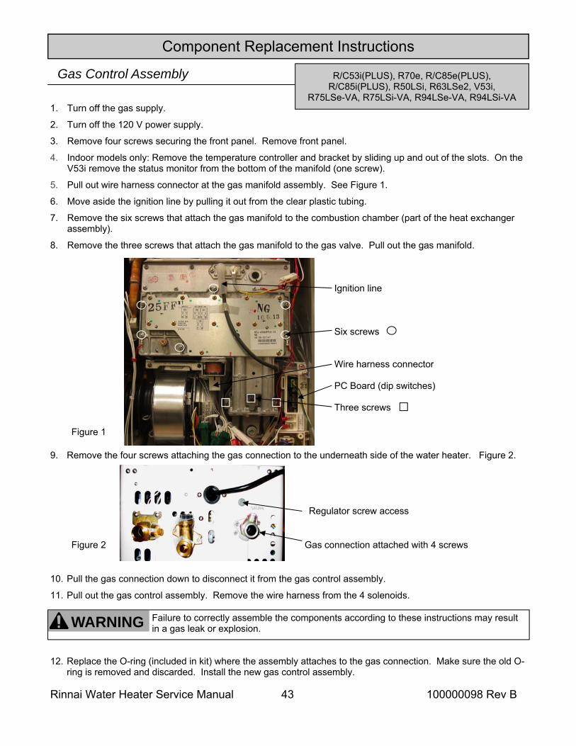
Tankless Water Heater Service Manual
Key to Trade Names in this Manual: R/C Indicates both the residential and
commercial versions. R/C42e includes R42e and C42e.
RC Indicates condensing water heater models.
(PLUS) Indicates that the Designer Plus models are included. R/C85ePLUS includes R85e, C85e, and R85ePLUS. On the side of the water heater, the trade name includes a “D”, as in R85De.
(ASME) Indicates that the ASME models are included. R98LSe(ASME) includes the R98LSe and R98LSeASME.
-VA,-VB The trade names R75LSe, R75LSi, R94LSe, and R94LSi have been given to both the VA and VB series of water heaters. Pay close attention to the particular model number when referencing electrical diagnostics, wire diagrams, gas pressures, replacement instructions, and for parts. When there is a difference –VA or –VB will be specified.
Model with valves in carton Equivalent Model
RV53e V53e
RV53i V53i
RL75e R75LSe-VB
RL75i R75LSi-VB
RL94e R94LSe-VB
RL94i R94LSi-VB
RC80e RC80HPe
RC80i RC80HPi
RC98e RC98HPe
RC98i RC98HPi
Some of the trade names for models were changed to indicate that their cartons included isolation valves and a pressure relief valve. For service and repair purposes the table below shows the equivalent models.
R/C42e, R/C53e 10 28 41 49 54 59 69
R70e, R/C85e(PLUS) 12 29 43 50 56 65 72
R/C53i(PLUS), R/C85i(PLUS) 12 30 43 51 56 65 76
R/C98e(ASME) 14 31 45 52 56 67 80
R/C98i(ASME) 14 31 45 52 56 67 82
V53e, R63LSe 16 32 41 49 55 60 69
R50LSi, R75LSi-VA 18 33 43 51 56 63 76
R63LSe2, R75LSe-VA 18 33 43 50 56 63 72
R94LSe-VA 18 33 43 50 56 63 72
R94LSi-VA 18 33 43 51 56 63 76
R75LSe-VB 20 34 47 50 56 63 72
R75LSi-VB 20 34 47 51 56 63 76
R94LSe-VB 20 34 47 50 56 63 72
R94LSi-VB 20 34 47 51 56 63 76
V53i 20 35 43 51 56 63 76
R98LSe(ASME) 22 36 45 52 58 67 80
R98LSi(ASME) 22 36 45 52 58 67 82
RC80HPe 24 37 47 53 56 68 85
RC80HPi 24 37 47 53 56 68 88
RC98HPe 26 38 48 53 56 68 91
RC98HPi 26 38 48 53 56 68 94
DIA
GN
OST
ICS
WIR
E D
IAG
RA
M
GA
S C
ON
TRO
L
FAN
PC B
OA
RD
WA
TER
FLO
W
CO
NTR
OL
HEA
T EX
CH
AN
GER
MO
DEL
S
This manual provides service information for the models below. This table cross references each model to the applicable page number for internal component replacement instructions.
100000098 Rev B
Rinnai Water Heater Service Manual 2 100000098 Rev B
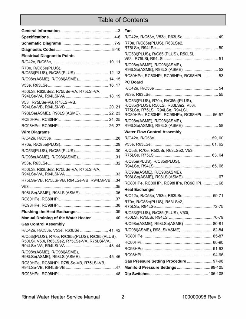
Table of Contents General Information .................................................... 3 Specifications .......................................................... 4-6 Schematic Diagrams ............................................... 7-9 Diagnostic Codes .................................................. 8-10 Electrical Diagnostic Points R/C42e, R/C53e, ................................................. 10, 11 R70e, R/C85e(PLUS), R/C53i(PLUS), R/C85i(PLUS) ............................. 12, 13 R/C98e(ASME), R/C98i(ASME) ........................... 14, 15 V53e, R63LSe ...................................................... 16, 17 R50LSi, R63LSe2, R75LSe-VA, R75LSi-VA, R94LSe-VA, R94LSi-VA ...................................... 18, 19 V53i, R75LSe-VB, R75LSi-VB, R94LSe-VB, R94LSi-VB ...................................... 20, 21 R98LSe(ASME), R98LSi(ASME) ......................... 22, 23 RC80HPe, RC80HPi ............................................ 24, 25 RC98HPe, RC98HPi ............................................ 26, 27 Wire Diagrams R/C42e, R/C53e .......................................................... 28 R70e, R/C85e(PLUS) .................................................. 29 R/C53i(PLUS), R/C85i(PLUS) ..................................... 30 R/C98e(ASME), R/C98i(ASME) .................................. 31 V53e, R63LSe ............................................................. 32 R50LSi, R63LSe2, R75LSe-VA, R75LSi-VA, R94LSe-VA, R94LSi-VA ............................................. 33 R75LSe-VB, R75LSi-VB, R94LSe-VB, R94LSi-VB .... 34 V53i ............................................................................. 35 R98LSe(ASME), R98LSi(ASME) ................................ 36 RC80HPe, RC80HPi ................................................... 37 RC98HPe, RC98HPi ................................................... 38 Flushing the Heat Exchanger ................................... 39 Manual Draining of the Water Heater ...................... 40 Gas Control Assembly R/C42e, R/C53e, V53e, R63LSe ......................... 41, 42 R/C53i(PLUS), R70e, R/C85e(PLUS), R/C85i(PLUS), R50LSi, V53i, R63LSe2, R75LSe-VA, R75LSi-VA, R94LSe-VA, R94LSi-VA ...................................... 43, 44 R/C98e(ASME), R/C98i(ASME), R98LSe(ASME), R98LSi(ASME) ......................... 45, 46 RC80HPe, RC80HPi, R75LSe-VB, R75LSi-VB, R94LSe-VB, R94LSi-VB ............................................. 47 RC98HPe, RC98HPi ................................................... 48
Fan R/C42e, R/C53e, V53e, R63LSe ................................ 49 R70e, R/C85e(PLUS), R63LSe2, R75LSe, R94LSe........................................................ 50 R/C53i(PLUS), R/C85i(PLUS), R50LSi, V53i, R75LSi, R94LSi ................................................. 51 R/C98e(ASME), R/C98i(ASME), R98LSe(ASME), R98LSi(ASME) ............................... 52 RC80HPe, RC80HPi, RC98HPe, RC98HPi ............... 53 PC Board R/C42e, R/C53e ......................................................... 54 V53e, R63LSe ............................................................ 55 R/C53i(PLUS), R70e, R/C85e(PLUS), R/C85i(PLUS), R50LSi, R63LSe2, V53i, R75LSe, R75LSi, R94LSe, R94LSi, RC80HPe, RC80HPi, RC98HPe, RC98HPi .......... 56-57 R/C98e(ASME), R/C98i(ASME), R98LSe(ASME), R98LSi(ASME) ............................... 58 Water Flow Control Assembly R/C42e, R/C53e ................................................... 59, 60 V53e, R63LSe ...................................................... 61, 62 R/C53i, R70e, R50LSi, R63LSe2, V53i, R75LSe, R75LSi ................................................... 63, 64 R/C85e(PLUS), R/C85i(PLUS), R94LSe, R94LSi ................................................... 65, 66 R/C98e(ASME), R/C98i(ASME), R98LSe(ASME), R98LSi(ASME) ............................... 67 RC80HPe, RC80HPi, RC98HPe, RC98HPi ............... 68 Heat Exchanger R/C42e, R/C53e, V53e, R63LSe ........................... 69-71 R70e, R/C85e(PLUS), R63LSe2, R75LSe, R94LSe................................................... 72-75 R/C53i(PLUS), R/C85i(PLUS), V53i, R50LSi, R75LSi, R94LSi ....................................... 76-79 R/C98e(ASME), R98LSe(ASME) .......................... 80-81 R/C98i(ASME), R98LSi(ASME) ............................ 82-84 RC80HPe .............................................................. 85-87 RC80HPi ................................................................ 88-90 RC98HPe .............................................................. 91-93 RC98HPi ................................................................ 94-96 Gas Pressure Setting Procedure ....................... 97-98 Manifold Pressure Settings .............................. 99-105 Dip Switches .................................................... 106-108
Rinnai Water Heater Service Manual 3 100000098 Rev B
General Information
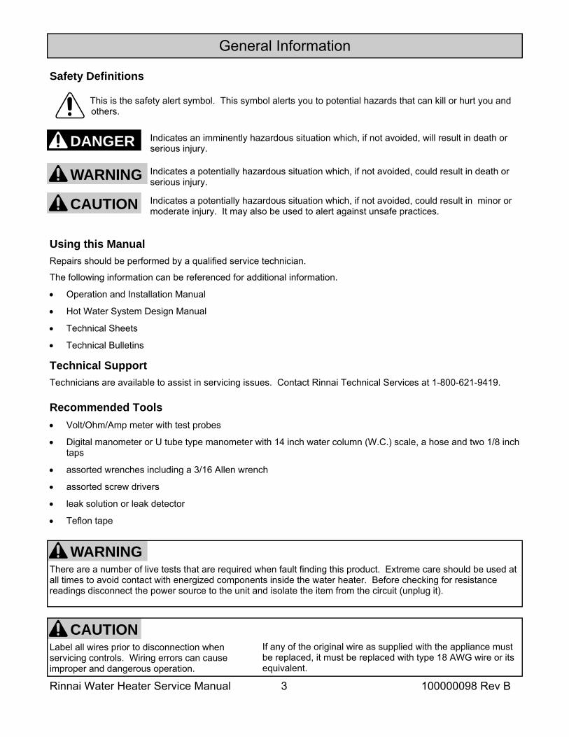
Safety Definitions This is the safety alert symbol. This symbol alerts you to potential hazards that can kill or hurt you and others.
Indicates an imminently hazardous situation which, if not avoided, will result in death or serious injury.
Indicates a potentially hazardous situation which, if not avoided, could result in death or serious injury.
Indicates a potentially hazardous situation which, if not avoided, could result in minor or moderate injury. It may also be used to alert against unsafe practices.
DANGER
CAUTION
WARNING
Recommended Tools • Volt/Ohm/Amp meter with test probes
• Digital manometer or U tube type manometer with 14 inch water column (W.C.) scale, a hose and two 1/8 inch taps
• assorted wrenches including a 3/16 Allen wrench
• assorted screw drivers
• leak solution or leak detector
• Teflon tape
Using this Manual Repairs should be performed by a qualified service technician.
The following information can be referenced for additional information.
• Operation and Installation Manual
• Hot Water System Design Manual
• Technical Sheets
• Technical Bulletins
Technical Support Technicians are available to assist in servicing issues. Contact Rinnai Technical Services at 1-800-621-9419.
WARNING There are a number of live tests that are required when fault finding this product. Extreme care should be used at all times to avoid contact with energized components inside the water heater. Before checking for resistance readings disconnect the power source to the unit and isolate the item from the circuit (unplug it).
If any of the original wire as supplied with the appliance must be replaced, it must be replaced with type 18 AWG wire or its equivalent.
Label all wires prior to disconnection when servicing controls. Wiring errors can cause improper and dangerous operation.
CAUTION
Rinnai Water Heater Service Manual 4 100000098 Rev B
Specifications
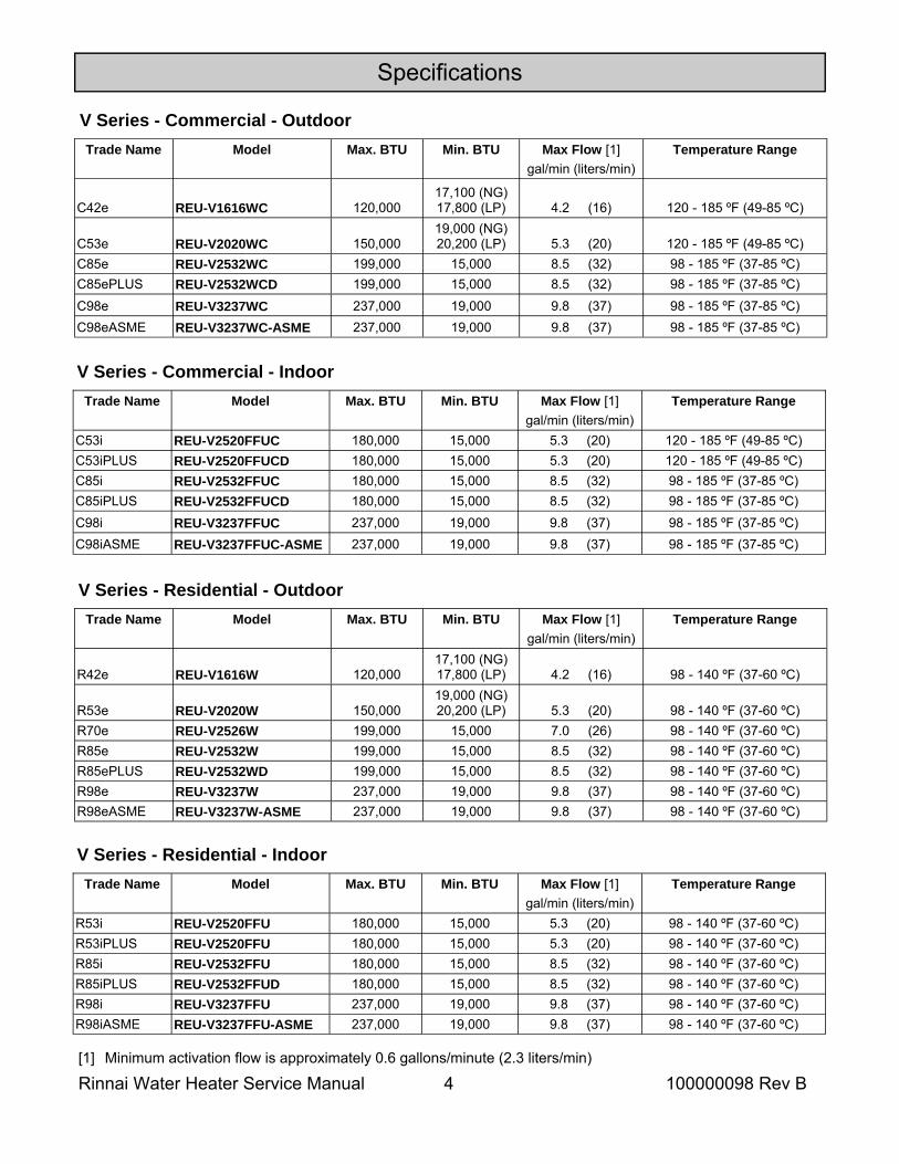
Trade Name Model Max. BTU Min. BTU Max Flow [1] gal/min (liters/min)
Temperature Range
C42e REU-V1616WC 120,000 17,100 (NG) 17,800 (LP) 4.2 (16) 120 - 185 ºF (49-85 ºC)
C53e REU-V2020WC 150,000 19,000 (NG) 20,200 (LP) 5.3 (20) 120 - 185 ºF (49-85 ºC)
C85e REU-V2532WC 199,000 15,000 8.5 (32) 98 - 185 ºF (37-85 ºC) C85ePLUS REU-V2532WCD 199,000 15,000 8.5 (32) 98 - 185 ºF (37-85 ºC) C98e REU-V3237WC 237,000 19,000 9.8 (37) 98 - 185 ºF (37-85 ºC) C98eASME REU-V3237WC-ASME 237,000 19,000 9.8 (37) 98 - 185 ºF (37-85 ºC)
V Series - Commercial - Outdoor
Trade Name Model Max. BTU Min. BTU Max Flow [1] gal/min (liters/min)
Temperature Range
C53i REU-V2520FFUC 180,000 15,000 5.3 (20) 120 - 185 ºF (49-85 ºC) C53iPLUS REU-V2520FFUCD 180,000 15,000 5.3 (20) 120 - 185 ºF (49-85 ºC) C85i REU-V2532FFUC 180,000 15,000 8.5 (32) 98 - 185 ºF (37-85 ºC) C85iPLUS REU-V2532FFUCD 180,000 15,000 8.5 (32) 98 - 185 ºF (37-85 ºC) C98i REU-V3237FFUC 237,000 19,000 9.8 (37) 98 - 185 ºF (37-85 ºC) C98iASME REU-V3237FFUC-ASME 237,000 19,000 9.8 (37) 98 - 185 ºF (37-85 ºC)
V Series - Commercial - Indoor
Trade Name Model Max. BTU Min. BTU Max Flow [1] gal/min (liters/min)
Temperature Range
R42e REU-V1616W 120,000 17,100 (NG) 17,800 (LP) 4.2 (16) 98 - 140 ºF (37-60 ºC)
R53e REU-V2020W 150,000 19,000 (NG) 20,200 (LP) 5.3 (20) 98 - 140 ºF (37-60 ºC)
R70e REU-V2526W 199,000 15,000 7.0 (26) 98 - 140 ºF (37-60 ºC) R85e REU-V2532W 199,000 15,000 8.5 (32) 98 - 140 ºF (37-60 ºC) R85ePLUS REU-V2532WD 199,000 15,000 8.5 (32) 98 - 140 ºF (37-60 ºC) R98e REU-V3237W 237,000 19,000 9.8 (37) 98 - 140 ºF (37-60 ºC) R98eASME REU-V3237W-ASME 237,000 19,000 9.8 (37) 98 - 140 ºF (37-60 ºC)
V Series - Residential - Outdoor
[1] Minimum activation flow is approximately 0.6 gallons/minute (2.3 liters/min)
Trade Name Model Max. BTU Min. BTU Max Flow [1] gal/min (liters/min)
Temperature Range
R53i REU-V2520FFU 180,000 15,000 5.3 (20) 98 - 140 ºF (37-60 ºC) R53iPLUS REU-V2520FFU 180,000 15,000 5.3 (20) 98 - 140 ºF (37-60 ºC) R85i REU-V2532FFU 180,000 15,000 8.5 (32) 98 - 140 ºF (37-60 ºC) R85iPLUS REU-V2532FFUD 180,000 15,000 8.5 (32) 98 - 140 ºF (37-60 ºC) R98i REU-V3237FFU 237,000 19,000 9.8 (37) 98 - 140 ºF (37-60 ºC) R98iASME REU-V3237FFU-ASME 237,000 19,000 9.8 (37) 98 - 140 ºF (37-60 ºC)
V Series - Residential - Indoor
Rinnai Water Heater Service Manual 5 100000098 Rev B
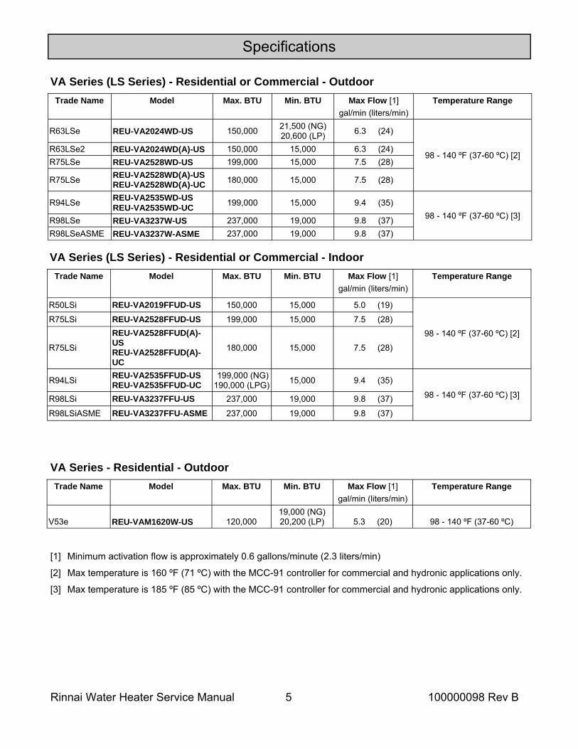
Specifications
[1] Minimum activation flow is approximately 0.6 gallons/minute (2.3 liters/min)
[2] Max temperature is 160 ºF (71 ºC) with the MCC-91 controller for commercial and hydronic applications only.
[3] Max temperature is 185 ºF (85 ºC) with the MCC-91 controller for commercial and hydronic applications only.
Trade Name Model Max. BTU Min. BTU Max Flow [1] gal/min (liters/min)
Temperature Range
R63LSe REU-VA2024WD-US 150,000 21,500 (NG) 20,600 (LP) 6.3 (24)
98 - 140 ºF (37-60 ºC) [2] R63LSe2 REU-VA2024WD(A)-US 150,000 15,000 6.3 (24) R75LSe REU-VA2528WD-US 199,000 15,000 7.5 (28)
R75LSe REU-VA2528WD(A)-US REU-VA2528WD(A)-UC 180,000 15,000 7.5 (28)
R94LSe REU-VA2535WD-US REU-VA2535WD-UC 199,000 15,000 9.4 (35)
R98LSe REU-VA3237W-US 237,000 19,000 9.8 (37) R98LSeASME REU-VA3237W-ASME 237,000 19,000 9.8 (37)
98 - 140 ºF (37-60 ºC) [3]
VA Series (LS Series) - Residential or Commercial - Outdoor
Trade Name Model Max. BTU Min. BTU Max Flow [1] gal/min (liters/min)
Temperature Range
R50LSi REU-VA2019FFUD-US 150,000 15,000 5.0 (19)
98 - 140 ºF (37-60 ºC) [2] R75LSi REU-VA2528FFUD-US 199,000 15,000 7.5 (28)
R75LSi
REU-VA2528FFUD(A)-US REU-VA2528FFUD(A)-UC
180,000 15,000 7.5 (28)
R94LSi REU-VA2535FFUD-US REU-VA2535FFUD-UC
199,000 (NG) 190,000 (LPG) 15,000 9.4 (35)
98 - 140 ºF (37-60 ºC) [3] R98LSi REU-VA3237FFU-US 237,000 19,000 9.8 (37)
R98LSiASME REU-VA3237FFU-ASME 237,000 19,000 9.8 (37)
VA Series (LS Series) - Residential or Commercial - Indoor
Trade Name Model Max. BTU Min. BTU Max Flow [1] gal/min (liters/min)
Temperature Range
V53e REU-VAM1620W-US 120,000 19,000 (NG) 20,200 (LP) 5.3 (20) 98 - 140 ºF (37-60 ºC)
VA Series - Residential - Outdoor
Rinnai Water Heater Service Manual 6 100000098 Rev B
Specifications
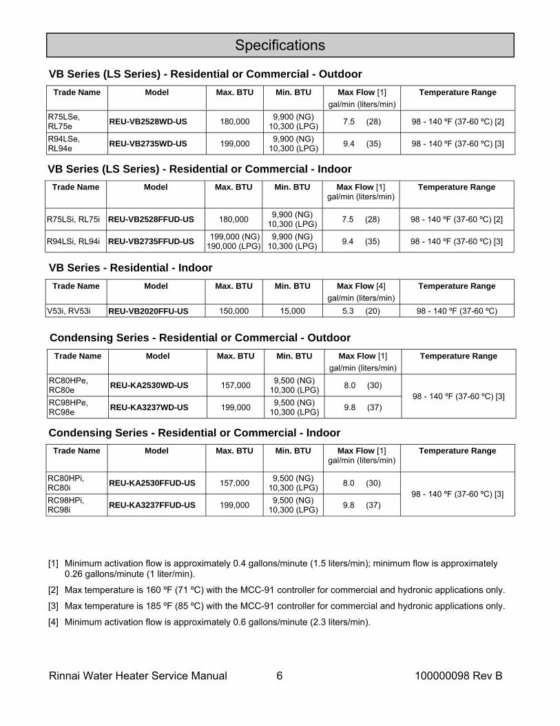
[1] Minimum activation flow is approximately 0.4 gallons/minute (1.5 liters/min); minimum flow is approximately 0.26 gallons/minute (1 liter/min).
[2] Max temperature is 160 ºF (71 ºC) with the MCC-91 controller for commercial and hydronic applications only.
[3] Max temperature is 185 ºF (85 ºC) with the MCC-91 controller for commercial and hydronic applications only.
[4] Minimum activation flow is approximately 0.6 gallons/minute (2.3 liters/min).
Trade Name Model Max. BTU Min. BTU Max Flow [1] gal/min (liters/min)
Temperature Range
R75LSe, RL75e REU-VB2528WD-US 180,000 9,900 (NG)
10,300 (LPG) 7.5 (28) 98 - 140 ºF (37-60 ºC) [2]
R94LSe, RL94e REU-VB2735WD-US 199,000 9,900 (NG)
10,300 (LPG) 9.4 (35) 98 - 140 ºF (37-60 ºC) [3]
VB Series (LS Series) - Residential or Commercial - Outdoor
Trade Name Model Max. BTU Min. BTU Max Flow [1] gal/min (liters/min)
Temperature Range
R75LSi, RL75i REU-VB2528FFUD-US 180,000 9,900 (NG) 10,300 (LPG) 7.5 (28) 98 - 140 ºF (37-60 ºC) [2]
R94LSi, RL94i REU-VB2735FFUD-US 199,000 (NG) 190,000 (LPG)
9,900 (NG) 10,300 (LPG) 9.4 (35) 98 - 140 ºF (37-60 ºC) [3]
VB Series (LS Series) - Residential or Commercial - Indoor
Trade Name Model Max. BTU Min. BTU Max Flow [4] gal/min (liters/min)
Temperature Range
V53i, RV53i REU-VB2020FFU-US 150,000 15,000 5.3 (20) 98 - 140 ºF (37-60 ºC)
VB Series - Residential - Indoor
Trade Name Model Max. BTU Min. BTU Max Flow [1] gal/min (liters/min)
Temperature Range
RC80HPe, RC80e REU-KA2530WD-US 157,000 9,500 (NG)
10,300 (LPG) 8.0 (30)
RC98HPe, RC98e REU-KA3237WD-US 199,000 9,500 (NG)
10,300 (LPG) 9.8 (37) 98 - 140 ºF (37-60 ºC) [3]
Condensing Series - Residential or Commercial - Outdoor
Trade Name Model Max. BTU Min. BTU Max Flow [1] gal/min (liters/min)
Temperature Range
RC80HPi, RC80i REU-KA2530FFUD-US 157,000 9,500 (NG)
10,300 (LPG) 8.0 (30)
RC98HPi, RC98i REU-KA3237FFUD-US 199,000 9,500 (NG)
10,300 (LPG) 9.8 (37) 98 - 140 ºF (37-60 ºC) [3]
Condensing Series - Residential or Commercial - Indoor
Rinnai Water Heater Service Manual 7 100000098 Rev B
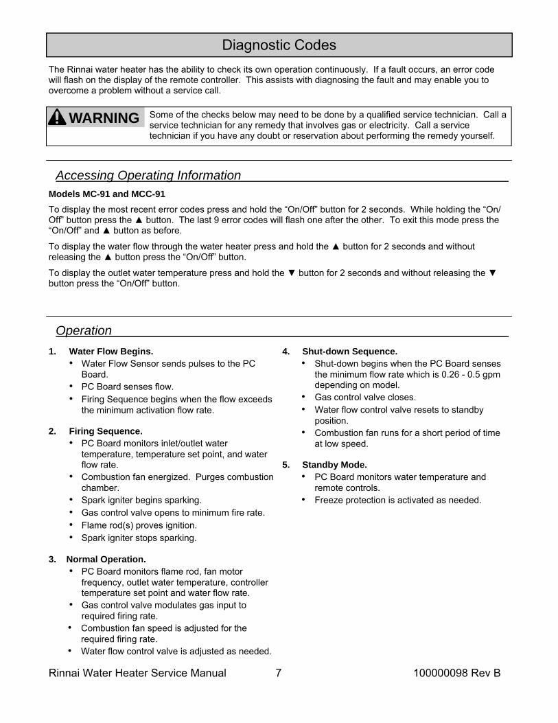
Diagnostic Codes The Rinnai water heater has the ability to check its own operation continuously. If a fault occurs, an error code will flash on the display of the remote controller. This assists with diagnosing the fault and may enable you to overcome a problem without a service call.
Some of the checks below may need to be done by a qualified service technician. Call a service technician for any remedy that involves gas or electricity. Call a service technician if you have any doubt or reservation about performing the remedy yourself.
WARNING
Accessing Operating Information
To display the most recent error codes press and hold the “On/Off” button for 2 seconds. While holding the “On/Off” button press the button. The last 9 error codes will flash one after the other. To exit this mode press the “On/Off” and button as before.
To display the water flow through the water heater press and hold the button for 2 seconds and without releasing the button press the “On/Off” button.
To display the outlet water temperature press and hold the button for 2 seconds and without releasing the button press the “On/Off” button.
Models MC-91 and MCC-91
1. Water Flow Begins. • Water Flow Sensor sends pulses to the PC
Board. • PC Board senses flow. • Firing Sequence begins when the flow exceeds
the minimum activation flow rate. 2. Firing Sequence.
• PC Board monitors inlet/outlet water temperature, temperature set point, and water flow rate.
• Combustion fan energized. Purges combustion chamber.
• Spark igniter begins sparking. • Gas control valve opens to minimum fire rate. • Flame rod(s) proves ignition. • Spark igniter stops sparking.
3. Normal Operation.
• PC Board monitors flame rod, fan motor frequency, outlet water temperature, controller temperature set point and water flow rate.
• Gas control valve modulates gas input to required firing rate.
• Combustion fan speed is adjusted for the required firing rate.
• Water flow control valve is adjusted as needed.
4. Shut-down Sequence. • Shut-down begins when the PC Board senses
the minimum flow rate which is 0.26 - 0.5 gpm depending on model.
• Gas control valve closes. • Water flow control valve resets to standby
position. • Combustion fan runs for a short period of time
at low speed. 5. Standby Mode.
• PC Board monitors water temperature and remote controls.
• Freeze protection is activated as needed.
Operation
Rinnai Water Heater Service Manual 8 100000098 Rev B
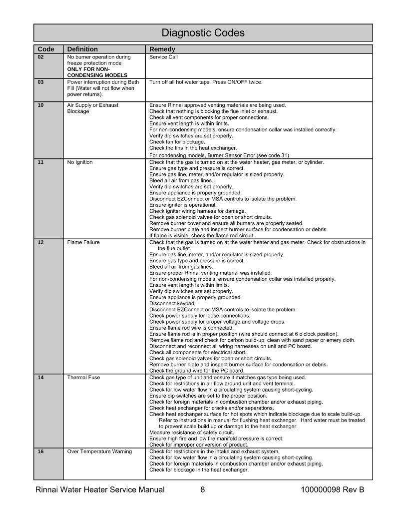
Diagnostic Codes Code Definition Remedy 02 No burner operation during
freeze protection mode ONLY FOR NON-CONDENSING MODELS
Service Call
03 Power interruption during Bath Fill (Water will not flow when power returns).
Turn off all hot water taps. Press ON/OFF twice.
10 Air Supply or Exhaust Blockage
Ensure Rinnai approved venting materials are being used. Check that nothing is blocking the flue inlet or exhaust. Check all vent components for proper connections. Ensure vent length is within limits. For non-condensing models, ensure condensation collar was installed correctly. Verify dip switches are set properly. Check fan for blockage. Check the fins in the heat exchanger. For condensing models, Burner Sensor Error (see code 31)
11 No Ignition Check that the gas is turned on at the water heater, gas meter, or cylinder. Ensure gas type and pressure is correct. Ensure gas line, meter, and/or regulator is sized properly. Bleed all air from gas lines. Verify dip switches are set properly. Ensure appliance is properly grounded. Disconnect EZConnect or MSA controls to isolate the problem. Ensure igniter is operational. Check igniter wiring harness for damage. Check gas solenoid valves for open or short circuits. Remove burner cover and ensure all burners are properly seated. Remove burner plate and inspect burner surface for condensation or debris. If flame is visible, check the flame rod circuit.
12 Flame Failure Check that the gas is turned on at the water heater and gas meter. Check for obstructions in the flue outlet.
Ensure gas line, meter, and/or regulator is sized properly. Ensure gas type and pressure is correct. Bleed all air from gas lines. Ensure proper Rinnai venting material was installed. For non-condensing models, ensure condensation collar was installed properly. Ensure vent length is within limits. Verify dip switches are set properly. Ensure appliance is properly grounded. Disconnect keypad. Disconnect EZConnect or MSA controls to isolate the problem. Check power supply for loose connections. Check power supply for proper voltage and voltage drops. Ensure flame rod wire is connected. Ensure flame rod is in proper position (wire should connect at 6 o’clock position). Remove flame rod and check for carbon build-up; clean with sand paper or emery cloth. Disconnect and reconnect all wiring harnesses on unit and PC board. Check all components for electrical short. Check gas solenoid valves for open or short circuits. Remove burner plate and inspect burner surface for condensation or debris. Check the ground wire for the PC board.
14 Thermal Fuse Check gas type of unit and ensure it matches gas type being used. Check for restrictions in air flow around unit and vent terminal. Check for low water flow in a circulating system causing short-cycling. Ensure dip switches are set to the proper position. Check for foreign materials in combustion chamber and/or exhaust piping. Check heat exchanger for cracks and/or separations. Check heat exchanger surface for hot spots which indicate blockage due to scale build-up.
Refer to instructions in manual for flushing heat exchanger. Hard water must be treated to prevent scale build up or damage to the heat exchanger.
Measure resistance of safety circuit. Ensure high fire and low fire manifold pressure is correct. Check for improper conversion of product.
16 Over Temperature Warning Check for restrictions in the intake and exhaust system. Check for low water flow in a circulating system causing short-cycling. Check for foreign materials in combustion chamber and/or exhaust piping. Check for blockage in the heat exchanger.
Rinnai Water Heater Service Manual 9 100000098 Rev B
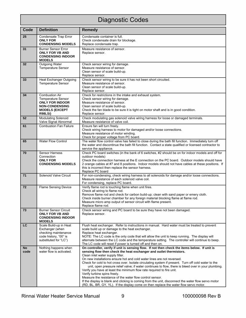
Code Definition Remedy 25
Condensate Trap Error ONLY FOR CONDENSING MODELS
Condensate container is full. Check condensate drain for blockage. Replace condensate trap.
31 Burner Sensor Error ONLY FOR VB AND CONDENSING INDOOR MODELS
Measure resistance of sensor. Replace sensor.
32 Outgoing Water Temperature Sensor
Check sensor wiring for damage. Measure resistance of sensor. Clean sensor of scale build-up. Replace sensor.
33 Heat Exchanger Outgoing Temperature Sensor
Check sensor wiring to be sure it has not been short circuited. Measure resistance of sensor. Clean sensor of scale build-up. Replace sensor.
34 Combustion Air Temperature Sensor ONLY FOR INDOOR NON-CONDENSING MODELS (EXCEPT R98LSi)
Check for restrictions in the intake and exhaust system. Check sensor wiring for damage. Measure resistance of sensor. Clean sensor of scale build-up. Check the fan blade to be sure it is tight on motor shaft and is in good condition. Replace sensor.
52 Modulating Solenoid Valve Signal Abnormal
Check modulating gas solenoid valve wiring harness for loose or damaged terminals. Measure resistance of valve coil.
61 Combustion Fan Failure Ensure fan will turn freely. Check wiring harness to motor for damaged and/or loose connections. Measure resistance of motor winding. Check for proper voltage from PC board.
65 Water Flow Control The water flow control valve has failed to close during the bath fill function. Immediately turn off the water and discontinue the bath fill function. Contact a state qualified or licensed contractor to service the appliance.
70 Sensor Harness Connection ONLY FOR CONDENSING MODELS
Check PC board switches (in the bank of 6 switches, #2 should be on for indoor models and off for outdoor models) Check the connection harness at the E connection on the PC board. Outdoor models should have 2 orange cables at #7 and 8 positions. Indoor models should not have cables at these positions. If this is incorrect then replace the sensor harness. Replace PC board
71 Solenoid Valve Circuit For non-condensing, check wiring harness to all solenoids for damage and/or loose connections. Measure resistance of each solenoid valve coil. For condensing, replace PC board.
72 Flame Sensing Device Verify flame rod is touching flame when unit fires. Check all wiring to flame rod. Remove flame rod and check for carbon build-up; clean with sand paper or emery cloth. Check inside burner chamber for any foreign material blocking flame at flame rod. Measure micro amp output of sensor circuit with flame present. Replace flame rod.
73 Burner Sensor Circuit ONLY FOR VB AND CONDENSING INDOOR MODELS
Check sensor wiring and PC board to be sure they have not been damaged. Replace sensor.
LC Scale Build-up in Heat Exchanger (when checking maintenance code history, “00” is substituted for “LC”)
Flush heat exchanger. Refer to instructions in manual. Hard water must be treated to prevent scale build up or damage to the heat exchanger. Replace heat exchanger. NOTE: The LC code is the only code that will allow the unit to keep running. The display will alternate between the LC code and the temperature setting. The controller will continue to beep. The LC code will reset if power is turned off and then on.
No code
Nothing happens when water flow is activated.
On controller, verify if unit is sensing flow. If not then check the items below. If unit is sensing flow then check the heat exchanger and outlet thermistors. Clean inlet water supply filter. On new installations ensure hot and cold water lines are not reversed. Check for cold to hot cross over. Isolate circulating system if present. Turn off cold water to the
unit, open pressure relief valve; if water continues to flow, there is bleed over in your plumbing. Verify you have at least the minimum flow rate required to fire unit. Verify turbine spins freely. Measure the resistance of the water flow control sensor. If the display is blank and clicking is coming from the unit, disconnect the water flow servo motor (RD, BL, BR, GY, YL). If the display come on then replace the water flow servo motor.
Diagnostic Codes
Rinnai Water Heater Service Manual 10 100000098 Rev B
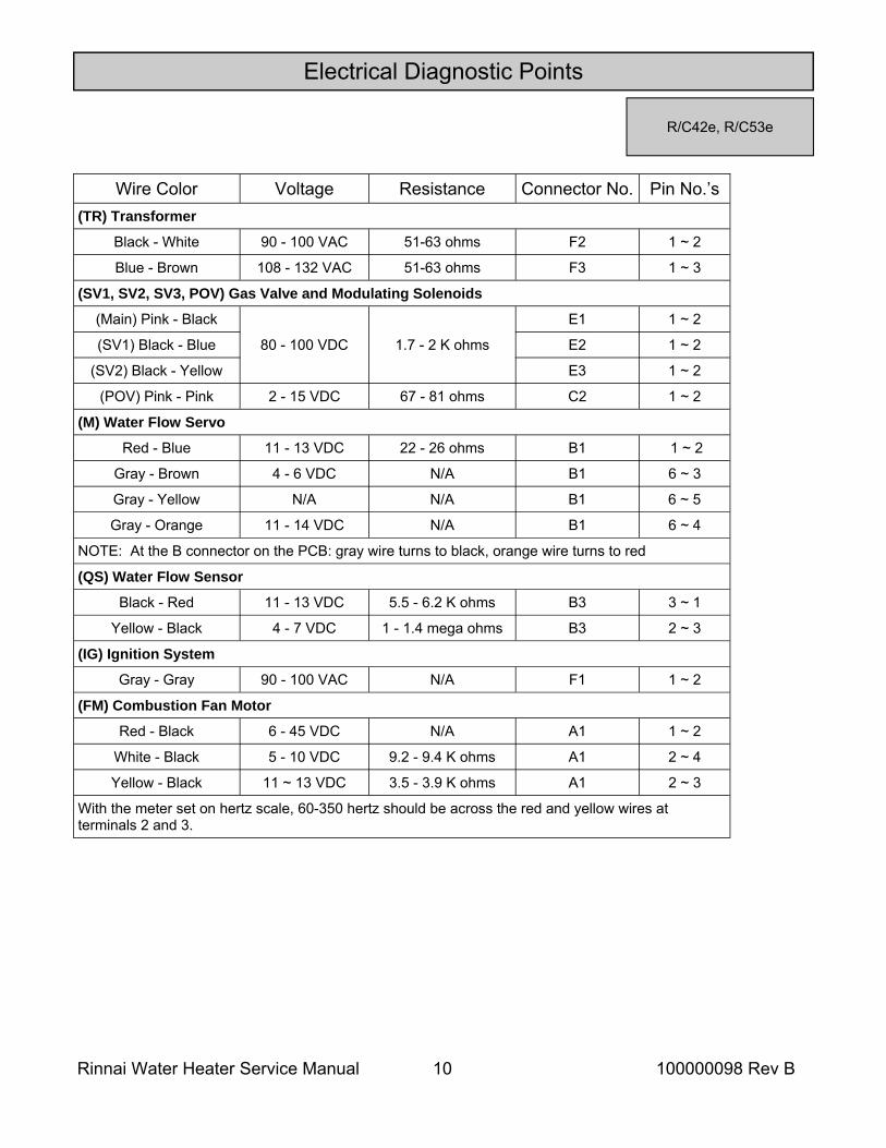
Electrical Diagnostic Points
Wire Color Voltage Resistance Connector No. Pin No.’s (TR) Transformer
Black - White 90 - 100 VAC 51-63 ohms F2 1 ~ 2
Blue - Brown 108 - 132 VAC 51-63 ohms F3 1 ~ 3
(SV1, SV2, SV3, POV) Gas Valve and Modulating Solenoids
(Main) Pink - Black
80 - 100 VDC 1.7 - 2 K ohms
E1 1 ~ 2
(SV1) Black - Blue E2 1 ~ 2
(SV2) Black - Yellow E3 1 ~ 2
(POV) Pink - Pink 2 - 15 VDC 67 - 81 ohms C2 1 ~ 2
(M) Water Flow Servo
Red - Blue 11 - 13 VDC 22 - 26 ohms B1 1 ~ 2
Gray - Brown 4 - 6 VDC N/A B1 6 ~ 3
Gray - Yellow N/A N/A B1 6 ~ 5
Gray - Orange 11 - 14 VDC N/A B1 6 ~ 4
NOTE: At the B connector on the PCB: gray wire turns to black, orange wire turns to red
(QS) Water Flow Sensor
Black - Red 11 - 13 VDC 5.5 - 6.2 K ohms B3 3 ~ 1
Yellow - Black 4 - 7 VDC 1 - 1.4 mega ohms B3 2 ~ 3
(IG) Ignition System
Gray - Gray 90 - 100 VAC N/A F1 1 ~ 2
(FM) Combustion Fan Motor
Red - Black 6 - 45 VDC N/A A1 1 ~ 2
White - Black 5 - 10 VDC 9.2 - 9.4 K ohms A1 2 ~ 4
Yellow - Black 11 ~ 13 VDC 3.5 - 3.9 K ohms A1 2 ~ 3
With the meter set on hertz scale, 60-350 hertz should be across the red and yellow wires at terminals 2 and 3.
R/C42e, R/C53e
Rinnai Water Heater Service Manual 11 100000098 Rev B
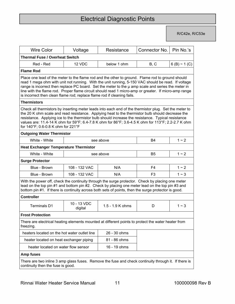
Electrical Diagnostic Points
Wire Color Voltage Resistance Connector No. Pin No.’s Thermal Fuse / Overheat Switch
Red - Red 12 VDC below 1 ohm B, C 6 (B) ~ 1 (C)
Flame Rod
Place one lead of the meter to the flame rod and the other to ground. Flame rod to ground should read 1 mega ohm with unit not running. With the unit running, 5-150 VAC should be read. If voltage range is incorrect then replace PC board. Set the meter to the μ amp scale and series the meter in line with the flame rod. Proper flame circuit should read 1 micro-amp or greater. If micro-amp range is incorrect then clean flame rod; replace flame rod if cleaning fails.
Thermistors
Check all thermistors by inserting meter leads into each end of the thermistor plug. Set the meter to the 20 K ohm scale and read resistance. Applying heat to the thermistor bulb should decrease the resistance. Applying ice to the thermistor bulb should increase the resistance. Typical resistance values are: 11.4-14 K ohm for 59°F; 6.4-7.8 K ohm for 86°F; 3.6-4.5 K ohm for 113°F; 2.2-2.7 K ohm for 140°F; 0.6-0.8 K ohm for 221°F
Outgoing Water Thermistor
White - White see above B4 1 ~ 2
Heat Exchanger Temperature Thermistor
White - White see above B5 1 ~ 2
Surge Protector
Blue - Brown 108 - 132 VAC N/A F4 1 ~ 2
Blue - Brown 108 - 132 VAC N/A F3 1 ~ 3
With the power off, check the continuity through the surge protector. Check by placing one meter lead on the top pin #1 and bottom pin #2. Check by placing one meter lead on the top pin #3 and bottom pin #1. If there is continuity across both sets of points, then the surge protector is good.
Controller
Terminals D1 10 - 13 VDC digital 1.5 - 1.9 K ohms D 1 ~ 3
Frost Protection
There are electrical heating elements mounted at different points to protect the water heater from freezing.
heaters located on the hot water outlet line 26 - 30 ohms
heater located on heat exchanger piping 81 - 86 ohms
heater located on water flow sensor 16 - 19 ohms
Amp fuses
There are two inline 3 amp glass fuses. Remove the fuse and check continuity through it. If there is continuity then the fuse is good.
R/C42e, R/C53e
Rinnai Water Heater Service Manual 12 100000098 Rev B
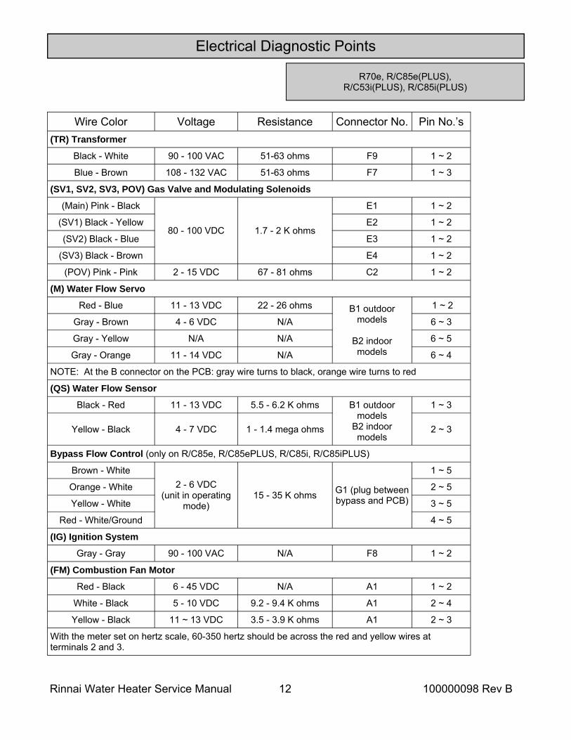
Electrical Diagnostic Points
R70e, R/C85e(PLUS), R/C53i(PLUS), R/C85i(PLUS)
Wire Color Voltage Resistance Connector No. Pin No.’s (TR) Transformer
Black - White 90 - 100 VAC 51-63 ohms F9 1 ~ 2
Blue - Brown 108 - 132 VAC 51-63 ohms F7 1 ~ 3
(SV1, SV2, SV3, POV) Gas Valve and Modulating Solenoids
(Main) Pink - Black
80 - 100 VDC 1.7 - 2 K ohms
E1 1 ~ 2
(SV1) Black - Yellow E2 1 ~ 2
(SV2) Black - Blue E3 1 ~ 2
(SV3) Black - Brown E4 1 ~ 2
(POV) Pink - Pink 2 - 15 VDC 67 - 81 ohms C2 1 ~ 2
(M) Water Flow Servo
Red - Blue 11 - 13 VDC 22 - 26 ohms B1 outdoor models
B2 indoor models
1 ~ 2
Gray - Brown 4 - 6 VDC N/A 6 ~ 3
Gray - Yellow N/A N/A 6 ~ 5
Gray - Orange 11 - 14 VDC N/A 6 ~ 4
NOTE: At the B connector on the PCB: gray wire turns to black, orange wire turns to red
(QS) Water Flow Sensor
Black - Red 11 - 13 VDC 5.5 - 6.2 K ohms 1 ~ 3
Yellow - Black 4 - 7 VDC 1 - 1.4 mega ohms 2 ~ 3
Bypass Flow Control (only on R/C85e, R/C85ePLUS, R/C85i, R/C85iPLUS)
Brown - White 2 - 6 VDC
(unit in operating mode)
15 - 35 K ohms G1 (plug between bypass and PCB)
1 ~ 5
Orange - White 2 ~ 5
Yellow - White 3 ~ 5
Red - White/Ground 4 ~ 5
(IG) Ignition System
Gray - Gray 90 - 100 VAC N/A F8 1 ~ 2
(FM) Combustion Fan Motor
Red - Black 6 - 45 VDC N/A A1 1 ~ 2
White - Black 5 - 10 VDC 9.2 - 9.4 K ohms A1 2 ~ 4
Yellow - Black 11 ~ 13 VDC 3.5 - 3.9 K ohms A1 2 ~ 3
With the meter set on hertz scale, 60-350 hertz should be across the red and yellow wires at terminals 2 and 3.
B1 outdoor models
B2 indoor models
Rinnai Water Heater Service Manual 13 100000098 Rev B
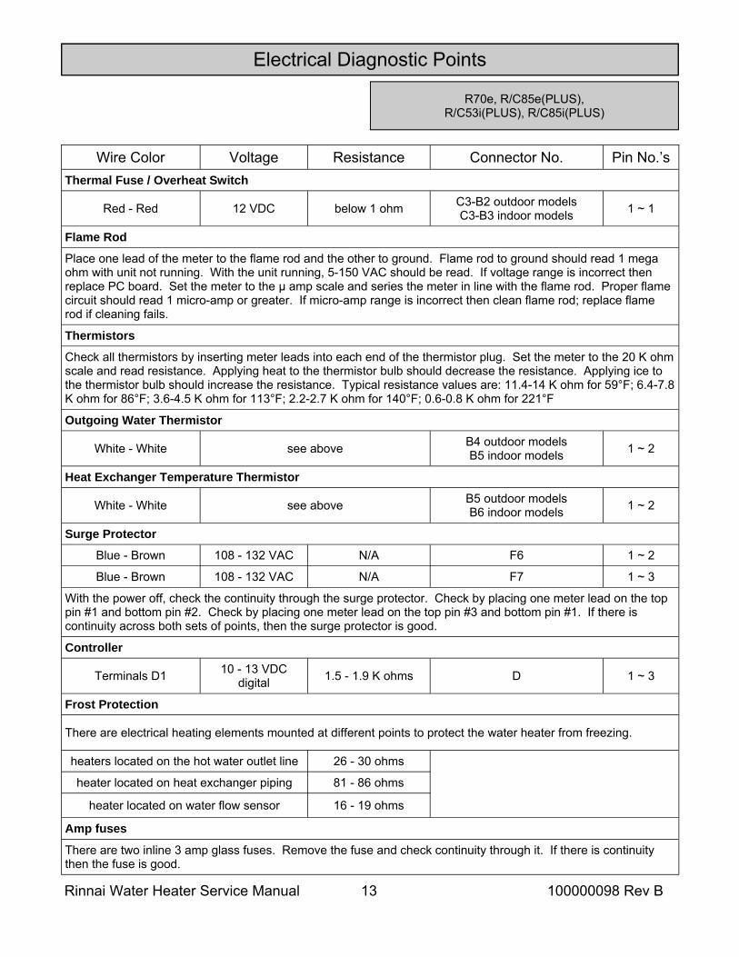
Electrical Diagnostic Points
Wire Color Voltage Resistance Connector No. Pin No.’s Thermal Fuse / Overheat Switch
Red - Red 12 VDC below 1 ohm C3-B2 outdoor models C3-B3 indoor models 1 ~ 1
Flame Rod
Place one lead of the meter to the flame rod and the other to ground. Flame rod to ground should read 1 mega ohm with unit not running. With the unit running, 5-150 VAC should be read. If voltage range is incorrect then replace PC board. Set the meter to the μ amp scale and series the meter in line with the flame rod. Proper flame circuit should read 1 micro-amp or greater. If micro-amp range is incorrect then clean flame rod; replace flame rod if cleaning fails.
Thermistors
Check all thermistors by inserting meter leads into each end of the thermistor plug. Set the meter to the 20 K ohm scale and read resistance. Applying heat to the thermistor bulb should decrease the resistance. Applying ice to the thermistor bulb should increase the resistance. Typical resistance values are: 11.4-14 K ohm for 59°F; 6.4-7.8 K ohm for 86°F; 3.6-4.5 K ohm for 113°F; 2.2-2.7 K ohm for 140°F; 0.6-0.8 K ohm for 221°F
Outgoing Water Thermistor
White - White see above B4 outdoor models B5 indoor models 1 ~ 2
Heat Exchanger Temperature Thermistor
White - White see above B5 outdoor models B6 indoor models 1 ~ 2
Surge Protector
Blue - Brown 108 - 132 VAC N/A F6 1 ~ 2
Blue - Brown 108 - 132 VAC N/A F7 1 ~ 3
With the power off, check the continuity through the surge protector. Check by placing one meter lead on the top pin #1 and bottom pin #2. Check by placing one meter lead on the top pin #3 and bottom pin #1. If there is continuity across both sets of points, then the surge protector is good.
Controller
Terminals D1 10 - 13 VDC digital 1.5 - 1.9 K ohms D 1 ~ 3
Frost Protection
There are electrical heating elements mounted at different points to protect the water heater from freezing.
heaters located on the hot water outlet line 26 - 30 ohms
heater located on heat exchanger piping 81 - 86 ohms
heater located on water flow sensor 16 - 19 ohms
Amp fuses
There are two inline 3 amp glass fuses. Remove the fuse and check continuity through it. If there is continuity then the fuse is good.
R70e, R/C85e(PLUS), R/C53i(PLUS), R/C85i(PLUS)
Rinnai Water Heater Service Manual 14 100000098 Rev B
Electrical Diagnostic Points
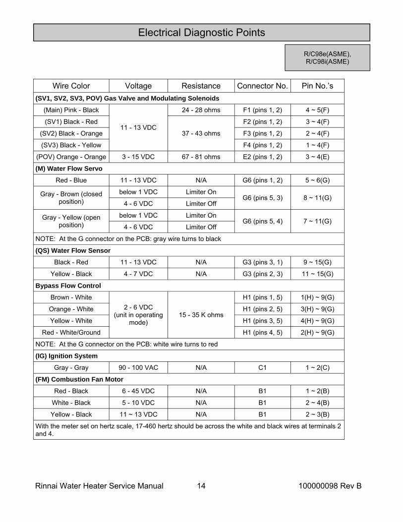
R/C98e(ASME), R/C98i(ASME)
Wire Color Voltage Resistance Connector No. Pin No.’s (SV1, SV2, SV3, POV) Gas Valve and Modulating Solenoids
(Main) Pink - Black
11 - 13 VDC
24 - 28 ohms F1 (pins 1, 2) 4 ~ 5(F)
(SV1) Black - Red F2 (pins 1, 2) 3 ~ 4(F)
(SV2) Black - Orange F3 (pins 1, 2) 2 ~ 4(F)
(SV3) Black - Yellow F4 (pins 1, 2) 1 ~ 4(F)
(POV) Orange - Orange 3 - 15 VDC 67 - 81 ohms E2 (pins 1, 2) 3 ~ 4(E)
(M) Water Flow Servo
Red - Blue 11 - 13 VDC N/A G6 (pins 1, 2) 5 ~ 6(G)
Gray - Brown (closed position)
below 1 VDC Limiter On G6 (pins 5, 3) 8 ~ 11(G)
4 - 6 VDC Limiter Off
Gray - Yellow (open position)
below 1 VDC Limiter On G6 (pins 5, 4) 7 ~ 11(G)
4 - 6 VDC Limiter Off
NOTE: At the G connector on the PCB: gray wire turns to black
(QS) Water Flow Sensor
Black - Red 11 - 13 VDC N/A G3 (pins 3, 1) 9 ~ 15(G)
Yellow - Black 4 - 7 VDC N/A G3 (pins 2, 3) 11 ~ 15(G)
Bypass Flow Control
Brown - White 2 - 6 VDC
(unit in operating mode)
15 - 35 K ohms
H1 (pins 1, 5) 1(H) ~ 9(G)
Orange - White 3(H) ~ 9(G)
Yellow - White 4(H) ~ 9(G)
Red - White/Ground 2(H) ~ 9(G)
NOTE: At the G connector on the PCB: white wire turns to red
(IG) Ignition System
Gray - Gray 90 - 100 VAC N/A C1 1 ~ 2(C)
(FM) Combustion Fan Motor
Red - Black 6 - 45 VDC N/A B1 1 ~ 2(B)
White - Black 5 - 10 VDC N/A B1 2 ~ 4(B)
Yellow - Black 11 ~ 13 VDC N/A B1 2 ~ 3(B)
With the meter set on hertz scale, 17-460 hertz should be across the white and black wires at terminals 2 and 4.
37 - 43 ohms
H1 (pins 2, 5)
H1 (pins 3, 5)
H1 (pins 4, 5)
Rinnai Water Heater Service Manual 15 100000098 Rev B
Electrical Diagnostic Points
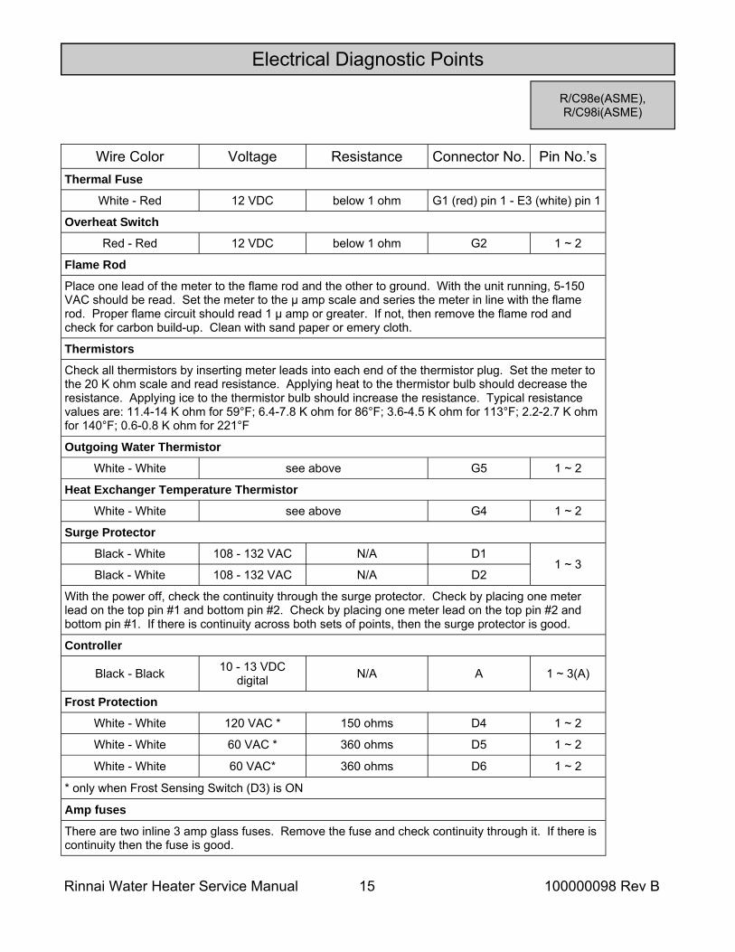
R/C98e(ASME), R/C98i(ASME)
Wire Color Voltage Resistance Connector No. Pin No.’s Thermal Fuse
White - Red 12 VDC below 1 ohm
Overheat Switch
Red - Red 12 VDC below 1 ohm G2 1 ~ 2
Flame Rod
Place one lead of the meter to the flame rod and the other to ground. With the unit running, 5-150 VAC should be read. Set the meter to the μ amp scale and series the meter in line with the flame rod. Proper flame circuit should read 1 μ amp or greater. If not, then remove the flame rod and check for carbon build-up. Clean with sand paper or emery cloth.
Thermistors
Check all thermistors by inserting meter leads into each end of the thermistor plug. Set the meter to the 20 K ohm scale and read resistance. Applying heat to the thermistor bulb should decrease the resistance. Applying ice to the thermistor bulb should increase the resistance. Typical resistance values are: 11.4-14 K ohm for 59°F; 6.4-7.8 K ohm for 86°F; 3.6-4.5 K ohm for 113°F; 2.2-2.7 K ohm for 140°F; 0.6-0.8 K ohm for 221°F
Outgoing Water Thermistor
White - White see above G5 1 ~ 2
Heat Exchanger Temperature Thermistor
White - White see above G4 1 ~ 2
Surge Protector
Black - White 108 - 132 VAC N/A D1 1 ~ 3
Black - White 108 - 132 VAC N/A D2
With the power off, check the continuity through the surge protector. Check by placing one meter lead on the top pin #1 and bottom pin #2. Check by placing one meter lead on the top pin #2 and bottom pin #1. If there is continuity across both sets of points, then the surge protector is good.
Controller
Black - Black 10 - 13 VDC digital N/A A 1 ~ 3(A)
Frost Protection
White - White 120 VAC * 150 ohms D4 1 ~ 2
White - White 60 VAC * 360 ohms D5 1 ~ 2
White - White 60 VAC* 360 ohms D6 1 ~ 2
* only when Frost Sensing Switch (D3) is ON
Amp fuses
There are two inline 3 amp glass fuses. Remove the fuse and check continuity through it. If there is continuity then the fuse is good.
G1 (red) pin 1 - E3 (white) pin 1
Rinnai Water Heater Service Manual 16 100000098 Rev B
Electrical Diagnostic Points
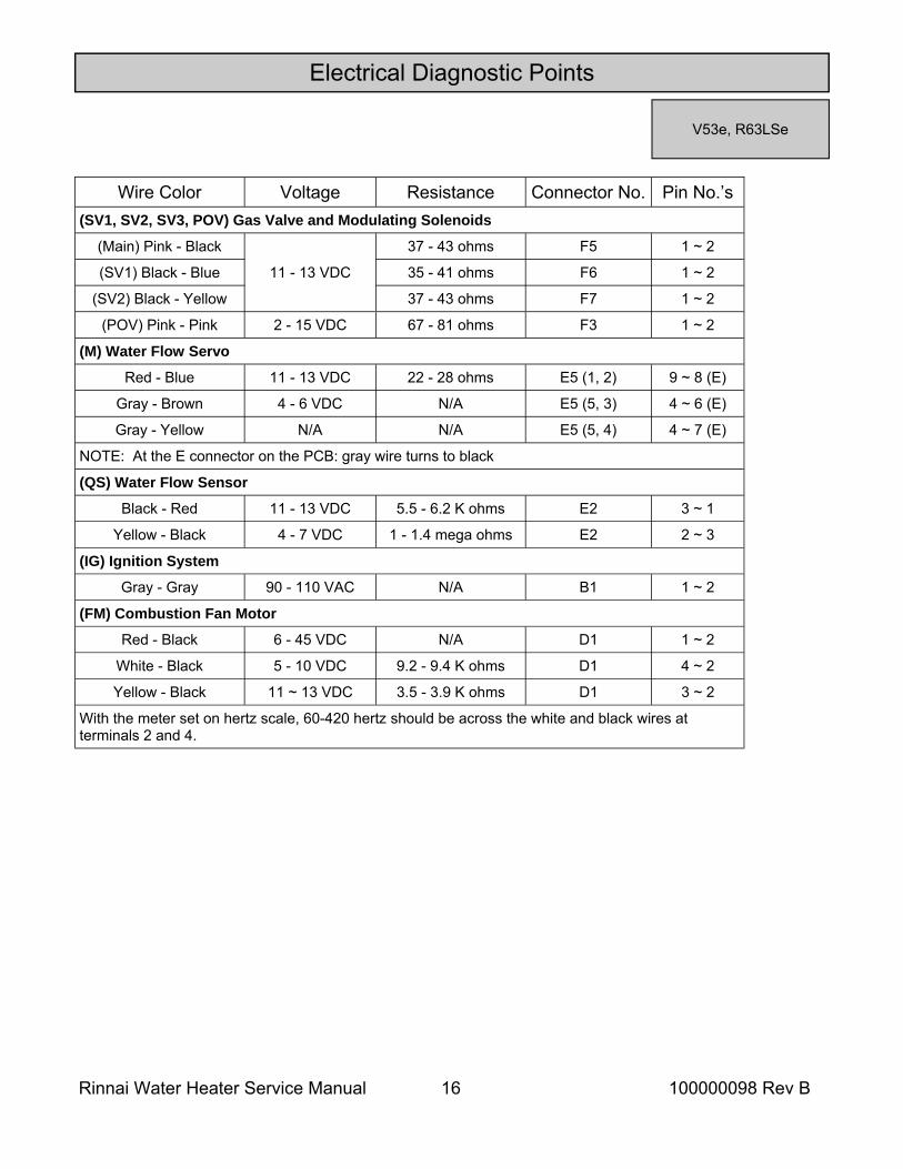
V53e, R63LSe
Wire Color Voltage Resistance Connector No. Pin No.’s (SV1, SV2, SV3, POV) Gas Valve and Modulating Solenoids
(Main) Pink - Black
11 - 13 VDC
37 - 43 ohms F5 1 ~ 2
(SV1) Black - Blue 35 - 41 ohms F6 1 ~ 2
(SV2) Black - Yellow 37 - 43 ohms F7 1 ~ 2
(POV) Pink - Pink 2 - 15 VDC 67 - 81 ohms F3 1 ~ 2
(M) Water Flow Servo
Red - Blue 11 - 13 VDC 22 - 28 ohms E5 (1, 2) 9 ~ 8 (E)
Gray - Brown 4 - 6 VDC N/A E5 (5, 3) 4 ~ 6 (E)
Gray - Yellow N/A N/A E5 (5, 4) 4 ~ 7 (E)
NOTE: At the E connector on the PCB: gray wire turns to black
(QS) Water Flow Sensor
Black - Red 11 - 13 VDC 5.5 - 6.2 K ohms E2 3 ~ 1
Yellow - Black 4 - 7 VDC 1 - 1.4 mega ohms E2 2 ~ 3
(IG) Ignition System
Gray - Gray 90 - 110 VAC N/A B1 1 ~ 2
(FM) Combustion Fan Motor
Red - Black 6 - 45 VDC N/A D1 1 ~ 2
White - Black 5 - 10 VDC 9.2 - 9.4 K ohms D1 4 ~ 2
Yellow - Black 11 ~ 13 VDC 3.5 - 3.9 K ohms D1 3 ~ 2
With the meter set on hertz scale, 60-420 hertz should be across the white and black wires at terminals 2 and 4.
Rinnai Water Heater Service Manual 17 100000098 Rev B
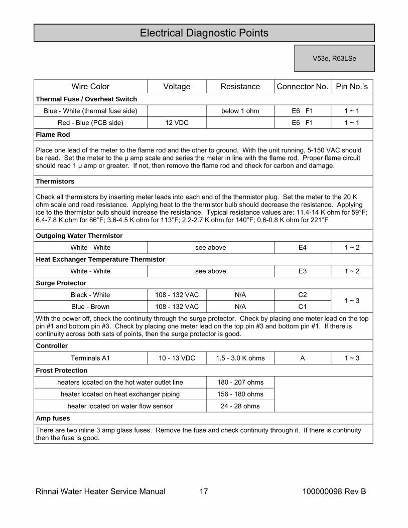
Wire Color Voltage Resistance Connector No. Pin No.’s Thermal Fuse / Overheat Switch
Blue - White (thermal fuse side) below 1 ohm E6 F1 1 ~ 1
Flame Rod
Place one lead of the meter to the flame rod and the other to ground. With the unit running, 5-150 VAC should be read. Set the meter to the μ amp scale and series the meter in line with the flame rod. Proper flame circuit should read 1 μ amp or greater. If not, then remove the flame rod and check for carbon and damage.
Thermistors
Check all thermistors by inserting meter leads into each end of the thermistor plug. Set the meter to the 20 K ohm scale and read resistance. Applying heat to the thermistor bulb should decrease the resistance. Applying ice to the thermistor bulb should increase the resistance. Typical resistance values are: 11.4-14 K ohm for 59°F; 6.4-7.8 K ohm for 86°F; 3.6-4.5 K ohm for 113°F; 2.2-2.7 K ohm for 140°F; 0.6-0.8 K ohm for 221°F
Outgoing Water Thermistor
White - White see above E4 1 ~ 2
Heat Exchanger Temperature Thermistor
White - White see above E3 1 ~ 2
Surge Protector
Black - White 108 - 132 VAC N/A C2 1 ~ 3
Blue - Brown 108 - 132 VAC N/A C1
With the power off, check the continuity through the surge protector. Check by placing one meter lead on the top pin #1 and bottom pin #3. Check by placing one meter lead on the top pin #3 and bottom pin #1. If there is continuity across both sets of points, then the surge protector is good.
Controller
Terminals A1 10 - 13 VDC 1.5 - 3.0 K ohms A 1 ~ 3
Frost Protection
heaters located on the hot water outlet line 180 - 207 ohms
heater located on heat exchanger piping 156 - 180 ohms
heater located on water flow sensor 24 - 28 ohms
Amp fuses
There are two inline 3 amp glass fuses. Remove the fuse and check continuity through it. If there is continuity then the fuse is good.
Red - Blue (PCB side) 12 VDC E6 F1 1 ~ 1
Electrical Diagnostic Points
V53e, R63LSe
Rinnai Water Heater Service Manual 18 100000098 Rev B
Electrical Diagnostic Points
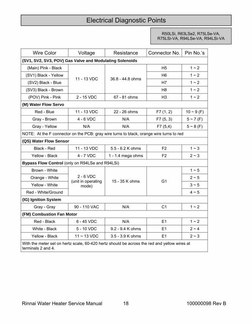
R50LSi, R63LSe2, R75LSe-VA, R75LSi-VA, R94LSe-VA, R94LSi-VA
Wire Color Voltage Resistance Connector No. Pin No.’s (SV1, SV2, SV3, POV) Gas Valve and Modulating Solenoids
(Main) Pink - Black
11 - 13 VDC 36.8 - 44.8 ohms
H5 1 ~ 2
(SV1) Black - Yellow H6 1 ~ 2
(SV2) Black - Blue H7 1 ~ 2
(SV3) Black - Brown H8 1 ~ 2
(POV) Pink - Pink 2 - 15 VDC 67 - 81 ohms H3 1 ~ 2
(M) Water Flow Servo
Red - Blue 11 - 13 VDC 22 - 26 ohms F7 (1, 2) 10 ~ 9 (F)
Gray - Brown 4 - 6 VDC N/A F7 (5, 3) 5 ~ 7 (F)
Gray - Yellow N/A N/A F7 (5,4) 5 ~ 8 (F)
NOTE: At the F connector on the PCB: gray wire turns to black, orange wire turns to red
(QS) Water Flow Sensor
Black - Red 11 - 13 VDC 5.5 - 6.2 K ohms F2 1 ~ 3
Yellow - Black 4 - 7 VDC 1 - 1.4 mega ohms F2 2 ~ 3
Bypass Flow Control (only on R94LSe and R94LSi)
Brown - White 2 - 6 VDC
(unit in operating mode)
15 - 35 K ohms G1
1 ~ 5
Orange - White 2 ~ 5
Yellow - White 3 ~ 5
Red - White/Ground 4 ~ 5
(IG) Ignition System
Gray - Gray 90 - 110 VAC N/A C1 1 ~ 2
(FM) Combustion Fan Motor
Red - Black 6 - 45 VDC N/A E1 1 ~ 2
White - Black 5 - 10 VDC 9.2 - 9.4 K ohms E1 2 ~ 4
Yellow - Black 11 ~ 13 VDC 3.5 - 3.9 K ohms E1 2 ~ 3
With the meter set on hertz scale, 60-420 hertz should be across the red and yellow wires at terminals 2 and 4.
Rinnai Water Heater Service Manual 19 100000098 Rev B
Electrical Diagnostic Points
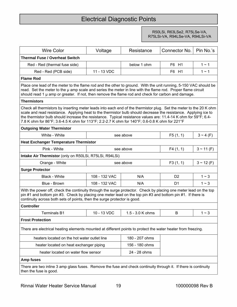
Wire Color Voltage Resistance Connector No. Pin No.’s Thermal Fuse / Overheat Switch
Red - Red (thermal fuse side) below 1 ohm F6 H1 1 ~ 1
Flame Rod
Place one lead of the meter to the flame rod and the other to ground. With the unit running, 5-150 VAC should be read. Set the meter to the μ amp scale and series the meter in line with the flame rod. Proper flame circuit should read 1 μ amp or greater. If not, then remove the flame rod and check for carbon and damage.
Thermistors
Check all thermistors by inserting meter leads into each end of the thermistor plug. Set the meter to the 20 K ohm scale and read resistance. Applying heat to the thermistor bulb should decrease the resistance. Applying ice to the thermistor bulb should increase the resistance. Typical resistance values are: 11.4-14 K ohm for 59°F; 6.4-7.8 K ohm for 86°F; 3.6-4.5 K ohm for 113°F; 2.2-2.7 K ohm for 140°F; 0.6-0.8 K ohm for 221°F
Outgoing Water Thermistor
White - White see above F5 (1, 1) 3 ~ 4 (F)
Heat Exchanger Temperature Thermistor
Pink - White see above F4 (1, 1) 3 ~ 11 (F)
Orange - White see above F3 (1, 1) 3 ~ 12 (F)
Surge Protector
Black - White 108 - 132 VAC N/A D2 1 ~ 3
Blue - Brown 108 - 132 VAC N/A D1 1 ~ 3
With the power off, check the continuity through the surge protector. Check by placing one meter lead on the top pin #1 and bottom pin #3. Check by placing one meter lead on the top pin #3 and bottom pin #1. If there is continuity across both sets of points, then the surge protector is good.
Controller
Terminals B1 10 - 13 VDC 1.5 - 3.0 K ohms B 1 ~ 3
Frost Protection
There are electrical heating elements mounted at different points to protect the water heater from freezing.
heaters located on the hot water outlet line 180 - 207 ohms
heater located on heat exchanger piping 156 - 180 ohms
heater located on water flow sensor 24 - 28 ohms
Amp fuses
There are two inline 3 amp glass fuses. Remove the fuse and check continuity through it. If there is continuity then the fuse is good.
Intake Air Thermistor (only on R50LSi, R75LSi, R94LSi)
Red - Red (PCB side) 11 - 13 VDC F6 H1 1 ~ 1
R50LSi, R63LSe2, R75LSe-VA, R75LSi-VA, R94LSe-VA, R94LSi-VA
Rinnai Water Heater Service Manual 20 100000098 Rev B
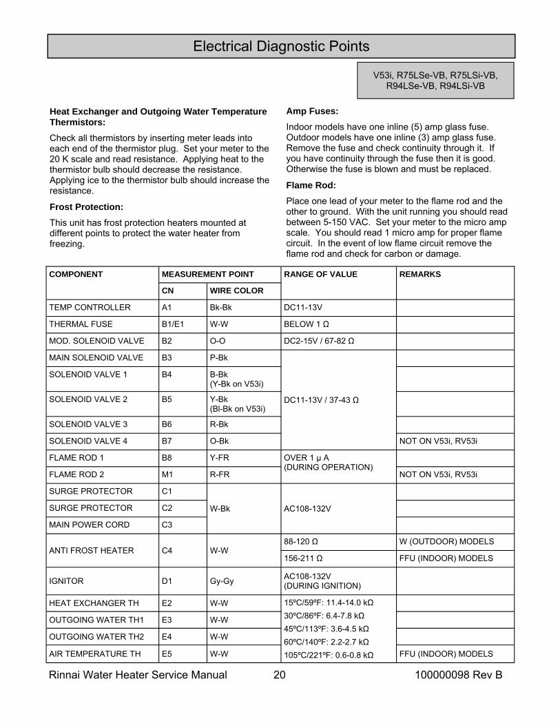
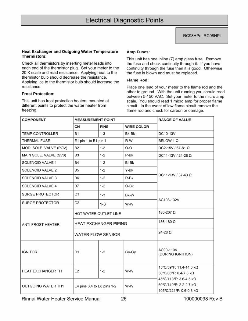
Heat Exchanger and Outgoing Water Temperature Thermistors: Check all thermistors by inserting meter leads into each end of the thermistor plug. Set your meter to the 20 K scale and read resistance. Applying heat to the thermistor bulb should decrease the resistance. Applying ice to the thermistor bulb should increase the resistance.
Frost Protection: This unit has frost protection heaters mounted at different points to protect the water heater from freezing.
Electrical Diagnostic Points
COMPONENT MEASUREMENT POINT RANGE OF VALUE REMARKS
CN WIRE COLOR
TEMP CONTROLLER A1 Bk-Bk DC11-13V
THERMAL FUSE B1/E1 W-W BELOW 1 Ω
MOD. SOLENOID VALVE B2 O-O DC2-15V / 67-82 Ω
MAIN SOLENOID VALVE B3 P-Bk
DC11-13V / 37-43 Ω
SOLENOID VALVE 1 B4 B-Bk (Y-Bk on V53i)
SOLENOID VALVE 2 B5 Y-Bk (Bl-Bk on V53i)
SOLENOID VALVE 3 B6 R-Bk
SOLENOID VALVE 4 B7 O-Bk NOT ON V53i, RV53i
FLAME ROD 1 B8 Y-FR OVER 1 µ A (DURING OPERATION)
FLAME ROD 2 M1 R-FR NOT ON V53i, RV53i
SURGE PROTECTOR C1
W-Bk AC108-132V
SURGE PROTECTOR C2
MAIN POWER CORD C3
ANTI FROST HEATER C4 W-W 88-120 Ω W (OUTDOOR) MODELS
156-211 Ω FFU (INDOOR) MODELS
IGNITOR D1 Gy-Gy AC108-132V (DURING IGNITION)
HEAT EXCHANGER TH E2 W-W 15ºC/59ºF: 11.4-14.0 kΩ 30ºC/86ºF: 6.4-7.8 kΩ 45ºC/113ºF: 3.6-4.5 kΩ 60ºC/140ºF: 2.2-2.7 kΩ 105ºC/221ºF: 0.6-0.8 kΩ
OUTGOING WATER TH1 E3 W-W
OUTGOING WATER TH2 E4 W-W
AIR TEMPERATURE TH E5 W-W FFU (INDOOR) MODELS
Amp Fuses: Indoor models have one inline (5) amp glass fuse. Outdoor models have one inline (3) amp glass fuse. Remove the fuse and check continuity through it. If you have continuity through the fuse then it is good. Otherwise the fuse is blown and must be replaced.
Flame Rod: Place one lead of your meter to the flame rod and the other to ground. With the unit running you should read between 5-150 VAC. Set your meter to the micro amp scale. You should read 1 micro amp for proper flame circuit. In the event of low flame circuit remove the flame rod and check for carbon or damage.
V53i, R75LSe-VB, R75LSi-VB, R94LSe-VB, R94LSi-VB
Rinnai Water Heater Service Manual 21 100000098 Rev B
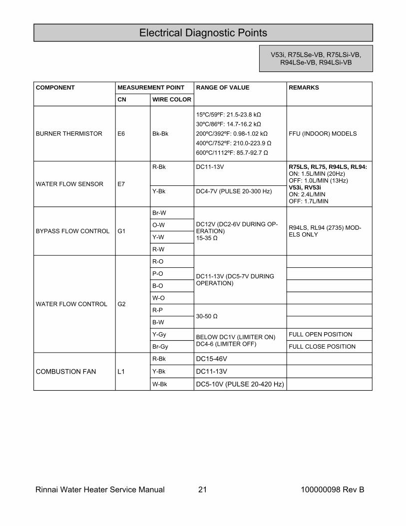
COMPONENT MEASUREMENT POINT RANGE OF VALUE REMARKS
CN WIRE COLOR
BURNER THERMISTOR E6 Bk-Bk
15ºC/59ºF: 21.5-23.8 kΩ 30ºC/86ºF: 14.7-16.2 kΩ 200ºC/392ºF: 0.98-1.02 kΩ 400ºC/752ºF: 210.0-223.9 Ω 600ºC/1112ºF: 85.7-92.7 Ω
FFU (INDOOR) MODELS
WATER FLOW SENSOR E7
R-Bk DC11-13V R75LS, RL75, R94LS, RL94: ON: 1.5L/MIN (20Hz) OFF: 1.0L/MIN (13Hz) V53i, RV53i ON: 2.4L/MIN OFF: 1.7L/MIN
Y-Bk DC4-7V (PULSE 20-300 Hz)
BYPASS FLOW CONTROL G1
Br-W
DC12V (DC2-6V DURING OP-ERATION) 15-35 Ω
R94LS, RL94 (2735) MOD-ELS ONLY
O-W
Y-W
R-W
WATER FLOW CONTROL G2
R-O
DC11-13V (DC5-7V DURING OPERATION)
P-O
B-O
W-O
R-P 30-50 Ω
B-W
Y-Gy BELOW DC1V (LIMITER ON) DC4-6 (LIMITER OFF)
FULL OPEN POSITION
Br-Gy FULL CLOSE POSITION
COMBUSTION FAN L1
R-Bk DC15-46V
Y-Bk DC11-13V
W-Bk DC5-10V (PULSE 20-420 Hz)
Electrical Diagnostic Points
V53i, R75LSe-VB, R75LSi-VB, R94LSe-VB, R94LSi-VB
Rinnai Water Heater Service Manual 22 100000098 Rev B
Electrical Diagnostic Points
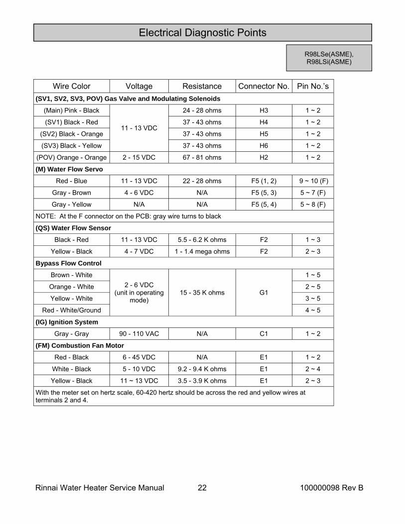
R98LSe(ASME), R98LSi(ASME)
Wire Color Voltage Resistance Connector No. Pin No.’s (SV1, SV2, SV3, POV) Gas Valve and Modulating Solenoids
(Main) Pink - Black
11 - 13 VDC
24 - 28 ohms H3 1 ~ 2
(SV1) Black - Red H4 1 ~ 2
(SV2) Black - Orange H5 1 ~ 2
(SV3) Black - Yellow H6 1 ~ 2
(POV) Orange - Orange 2 - 15 VDC 67 - 81 ohms H2 1 ~ 2
(M) Water Flow Servo
Red - Blue 11 - 13 VDC 22 - 28 ohms F5 (1, 2) 9 ~ 10 (F)
Gray - Brown 4 - 6 VDC N/A F5 (5, 3) 5 ~ 7 (F)
Gray - Yellow N/A N/A F5 (5, 4) 5 ~ 8 (F)
NOTE: At the F connector on the PCB: gray wire turns to black
(QS) Water Flow Sensor
Black - Red 11 - 13 VDC 5.5 - 6.2 K ohms F2 1 ~ 3
Yellow - Black 4 - 7 VDC 1 - 1.4 mega ohms F2 2 ~ 3
Bypass Flow Control
Brown - White 2 - 6 VDC
(unit in operating mode)
15 - 35 K ohms G1
1 ~ 5
Orange - White 2 ~ 5
Yellow - White 3 ~ 5
Red - White/Ground 4 ~ 5
(IG) Ignition System
Gray - Gray 90 - 110 VAC N/A C1 1 ~ 2
(FM) Combustion Fan Motor
Red - Black 6 - 45 VDC N/A E1 1 ~ 2
White - Black 5 - 10 VDC 9.2 - 9.4 K ohms E1 2 ~ 4
Yellow - Black 11 ~ 13 VDC 3.5 - 3.9 K ohms E1 2 ~ 3
With the meter set on hertz scale, 60-420 hertz should be across the red and yellow wires at terminals 2 and 4.
37 - 43 ohms
37 - 43 ohms
37 - 43 ohms
Rinnai Water Heater Service Manual 23 100000098 Rev B
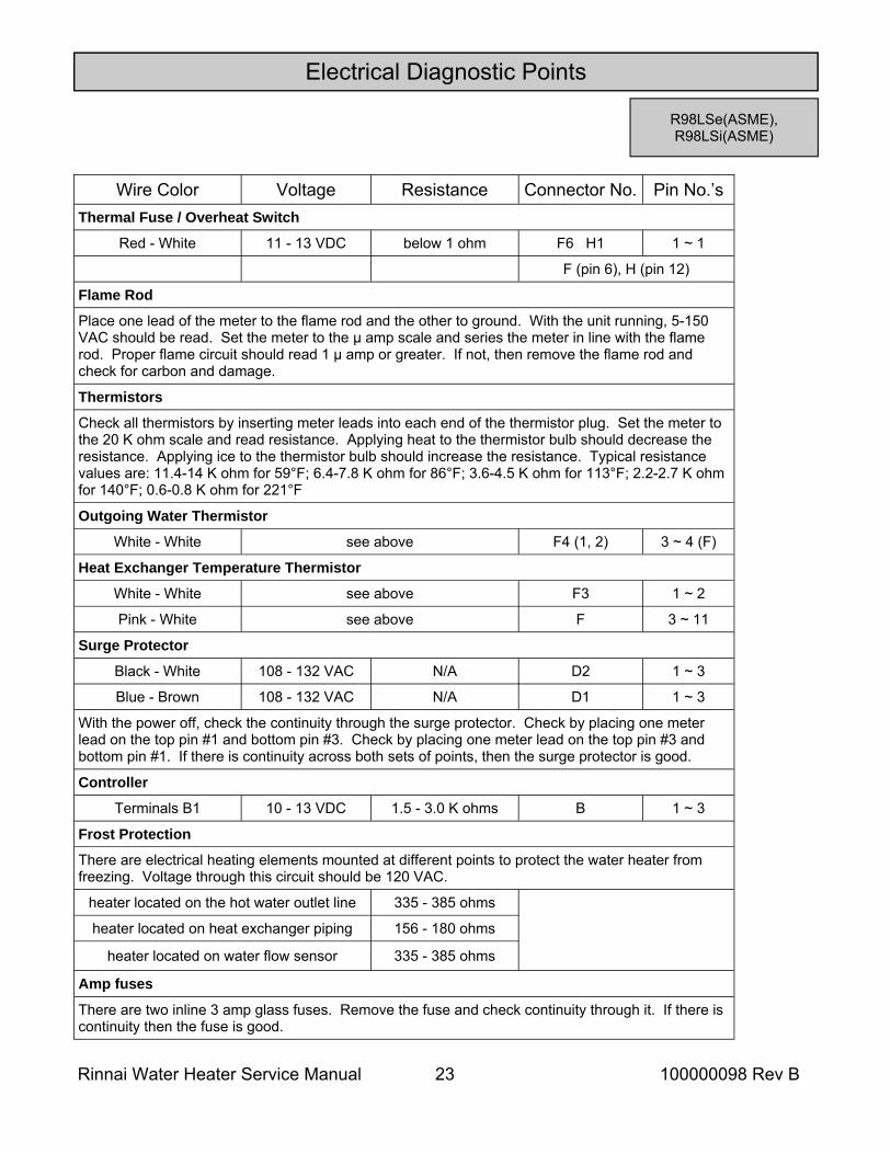
Electrical Diagnostic Points
Wire Color Voltage Resistance Connector No. Pin No.’s Thermal Fuse / Overheat Switch
Red - White 11 - 13 VDC below 1 ohm F6 H1 1 ~ 1
Flame Rod
Place one lead of the meter to the flame rod and the other to ground. With the unit running, 5-150 VAC should be read. Set the meter to the μ amp scale and series the meter in line with the flame rod. Proper flame circuit should read 1 μ amp or greater. If not, then remove the flame rod and check for carbon and damage.
Thermistors
Check all thermistors by inserting meter leads into each end of the thermistor plug. Set the meter to the 20 K ohm scale and read resistance. Applying heat to the thermistor bulb should decrease the resistance. Applying ice to the thermistor bulb should increase the resistance. Typical resistance values are: 11.4-14 K ohm for 59°F; 6.4-7.8 K ohm for 86°F; 3.6-4.5 K ohm for 113°F; 2.2-2.7 K ohm for 140°F; 0.6-0.8 K ohm for 221°F
Outgoing Water Thermistor
White - White see above F4 (1, 2) 3 ~ 4 (F)
Heat Exchanger Temperature Thermistor
White - White see above F3 1 ~ 2
Surge Protector
Black - White 108 - 132 VAC N/A D2 1 ~ 3
Blue - Brown 108 - 132 VAC N/A D1 1 ~ 3
With the power off, check the continuity through the surge protector. Check by placing one meter lead on the top pin #1 and bottom pin #3. Check by placing one meter lead on the top pin #3 and bottom pin #1. If there is continuity across both sets of points, then the surge protector is good.
Controller
Terminals B1 10 - 13 VDC 1.5 - 3.0 K ohms B 1 ~ 3
Frost Protection
There are electrical heating elements mounted at different points to protect the water heater from freezing. Voltage through this circuit should be 120 VAC.
heater located on the hot water outlet line 335 - 385 ohms
heater located on heat exchanger piping 156 - 180 ohms
heater located on water flow sensor 335 - 385 ohms
Amp fuses
There are two inline 3 amp glass fuses. Remove the fuse and check continuity through it. If there is continuity then the fuse is good.
F (pin 6), H (pin 12)
Pink - White see above F 3 ~ 11
R98LSe(ASME), R98LSi(ASME)
Rinnai Water Heater Service Manual 24 100000098 Rev B
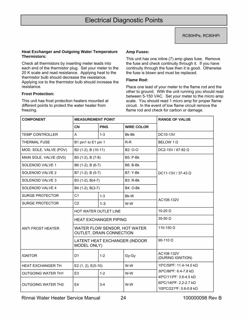
Heat Exchanger and Outgoing Water Temperature Thermistors: Check all thermistors by inserting meter leads into each end of the thermistor plug. Set your meter to the 20 K scale and read resistance. Applying heat to the thermistor bulb should decrease the resistance. Applying ice to the thermistor bulb should increase the resistance.
Frost Protection: This unit has frost protection heaters mounted at different points to protect the water heater from freezing.
Electrical Diagnostic Points
RC80HPe, RC80HPi
Amp Fuses: This unit has one inline (7) amp glass fuse. Remove the fuse and check continuity through it. If you have continuity through the fuse then it is good. Otherwise the fuse is blown and must be replaced.
Flame Rod: Place one lead of your meter to the flame rod and the other to ground. With the unit running you should read between 5-150 VAC. Set your meter to the micro amp scale. You should read 1 micro amp for proper flame circuit. In the event of low flame circuit remove the flame rod and check for carbon or damage.
COMPONENT MEASUREMENT POINT RANGE OF VALUE
CN PINS WIRE COLOR
TEMP CONTROLLER A 1-3 Bk-Bk DC10-13V
THERMAL FUSE B1 pin1 to E1 pin 1 R-R BELOW 1 Ω
MOD. SOLE. VALVE (POV) B2 (1-2), B (10-11) B2: O-O DC2-15V / 67-82 Ω
MAIN SOLE. VALVE (SV0) B5 (1-2), B (7-8) B5: P-Bk
DC11-13V / 37-43 Ω
SOLENOID VALVE 1 B6 (1-2), B (6-7) B6: B-Bk
SOLENOID VALVE 2 B7 (1-2), B (5-7) B7: Y-Bk
SOLENOID VALVE 3 B3 (1-2), B(4-7) B3: R-Bk
SOLENOID VALVE 4 B4 (1-2), B(3-7) B4: O-Bk
SURGE PROTECTOR C1 1-3 Bk-W AC108-132V
SURGE PROTECTOR C2 1-3 W-W
ANTI FROST HEATER
HOT WATER OUTLET LINE 10-20 Ω
HEAT EXCHANGER PIPING 35-50 Ω
WATER FLOW SENSOR, HOT WATER OUTLET, DRAIN CONNECTION
110-150 Ω
LATENT HEAT EXCHANGER (INDOOR MODEL ONLY)
90-110 Ω
IGNITOR D1 1-2 Gy-Gy AC108-132V (DURING IGNITION)
HEAT EXCHANGER TH W-W 15ºC/59ºF: 11.4-14.0 kΩ 30ºC/86ºF: 6.4-7.8 kΩ 45ºC/113ºF: 3.6-4.5 kΩ 60ºC/140ºF: 2.2-2.7 kΩ 105ºC/221ºF: 0.6-0.8 kΩ
OUTGOING WATER TH1 E3 1-2 W-W
OUTGOING WATER TH2 E4 3-4 W-W
E2 (1, 2), E(5-10)
Rinnai Water Heater Service Manual 25 100000098 Rev B
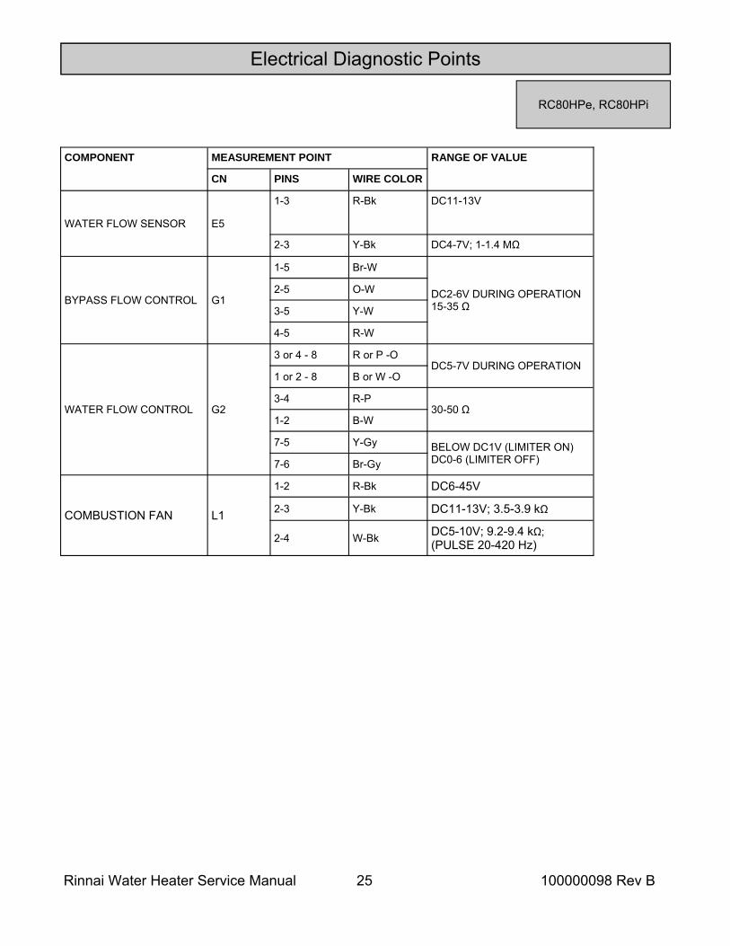
COMPONENT MEASUREMENT POINT RANGE OF VALUE
CN PINS WIRE COLOR
WATER FLOW SENSOR E5
1-3 R-Bk DC11-13V
2-3 Y-Bk DC4-7V; 1-1.4 MΩ
BYPASS FLOW CONTROL G1
1-5 Br-W
DC2-6V DURING OPERATION 15-35 Ω
2-5 O-W
3-5 Y-W
4-5 R-W
WATER FLOW CONTROL G2
3 or 4 - 8 R or P -O DC5-7V DURING OPERATION
1 or 2 - 8 B or W -O
3-4 R-P 30-50 Ω
1-2 B-W
7-5 Y-Gy BELOW DC1V (LIMITER ON) DC0-6 (LIMITER OFF) 7-6 Br-Gy
COMBUSTION FAN L1
1-2 R-Bk DC6-45V
2-3 Y-Bk DC11-13V; 3.5-3.9 kΩ
2-4 W-Bk DC5-10V; 9.2-9.4 kΩ; (PULSE 20-420 Hz)
Electrical Diagnostic Points
RC80HPe, RC80HPi
Rinnai Water Heater Service Manual 26 100000098 Rev B
Heat Exchanger and Outgoing Water Temperature Thermistors: Check all thermistors by inserting meter leads into each end of the thermistor plug. Set your meter to the 20 K scale and read resistance. Applying heat to the thermistor bulb should decrease the resistance. Applying ice to the thermistor bulb should increase the resistance.
Frost Protection: This unit has frost protection heaters mounted at different points to protect the water heater from freezing.
Electrical Diagnostic Points
RC98HPe, RC98HPi
Amp Fuses: This unit has one inline (7) amp glass fuse. Remove the fuse and check continuity through it. If you have continuity through the fuse then it is good. Otherwise the fuse is blown and must be replaced.
Flame Rod: Place one lead of your meter to the flame rod and the other to ground. With the unit running you should read between 5-150 VAC. Set your meter to the micro amp scale. You should read 1 micro amp for proper flame circuit. In the event of low flame circuit remove the flame rod and check for carbon or damage.
COMPONENT MEASUREMENT POINT RANGE OF VALUE
CN PINS WIRE COLOR
TEMP CONTROLLER B1 1-3 Bk-Bk DC10-13V
THERMAL FUSE E1 pin 1 to B1 pin 1 R-W BELOW 1 Ω
MOD. SOLE. VALVE (POV) B2 1-2 O-O DC2-15V / 67-81 Ω
MAIN SOLE. VALVE (SV0) B3 1-2 P-Bk DC11-13V / 24-28 Ω
SOLENOID VALVE 1 B4 1-2 Bl-Bk
DC11-13V / 37-43 Ω SOLENOID VALVE 2 B5 1-2 Y-Bk
SOLENOID VALVE 3 B6 1-2 R-Bk
SOLENOID VALVE 4 B7 1-2 O-Bk
SURGE PROTECTOR C1 1-3 Bk-W AC108-132V
SURGE PROTECTOR C2 1-3 W-W
ANTI FROST HEATER
HOT WATER OUTLET LINE 180-207 Ω
HEAT EXCHANGER PIPING 156-180 Ω
WATER FLOW SENSOR 24-28 Ω
IGNITOR D1 1-2 Gy-Gy AC90-110V (DURING IGNITION)
HEAT EXCHANGER TH E2 1-2 W-W 15ºC/59ºF: 11.4-14.0 kΩ 30ºC/86ºF: 6.4-7.8 kΩ 45ºC/113ºF: 3.6-4.5 kΩ 60ºC/140ºF: 2.2-2.7 kΩ 105ºC/221ºF: 0.6-0.8 kΩ
OUTGOING WATER TH1 W-W E4 pins 3,4 to E8 pins 1-2
Rinnai Water Heater Service Manual 27 100000098 Rev B
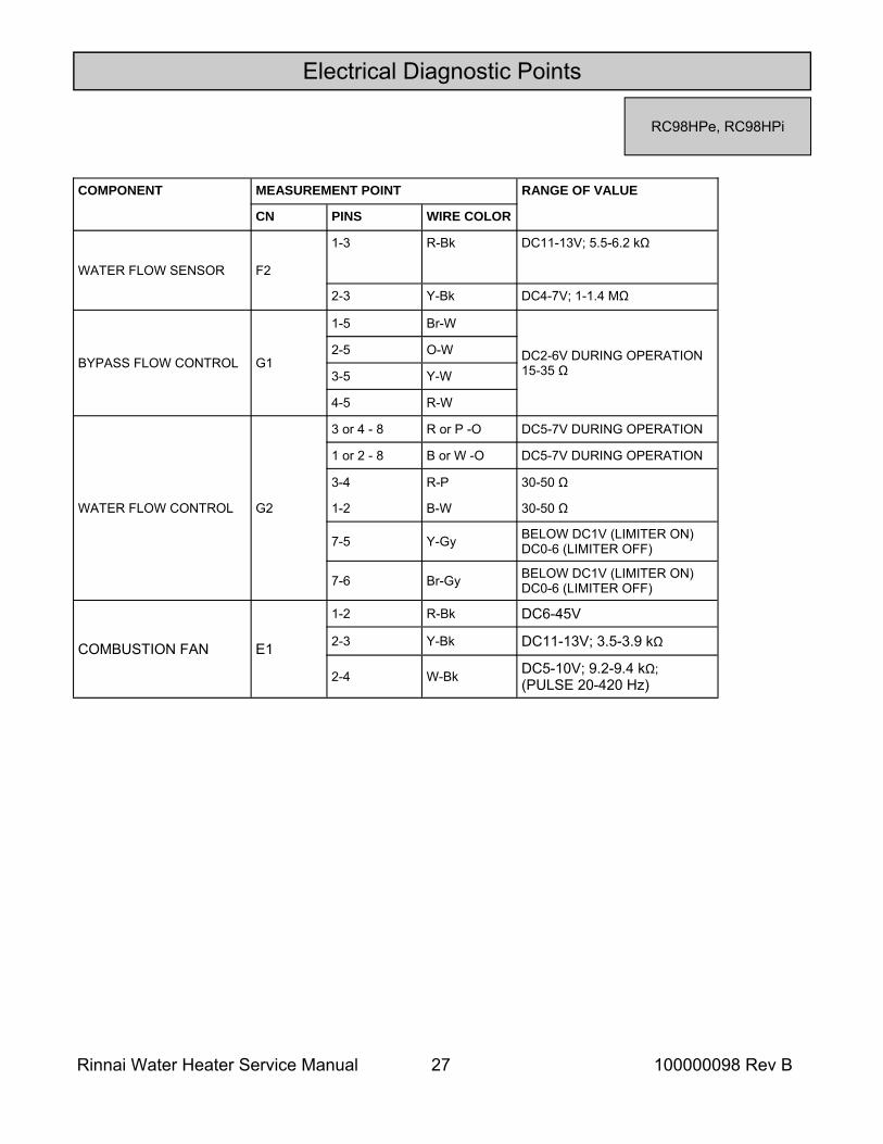
COMPONENT MEASUREMENT POINT RANGE OF VALUE
CN PINS WIRE COLOR
WATER FLOW SENSOR F2
1-3 R-Bk DC11-13V; 5.5-6.2 kΩ
2-3 Y-Bk DC4-7V; 1-1.4 MΩ
BYPASS FLOW CONTROL G1
1-5 Br-W
DC2-6V DURING OPERATION 15-35 Ω
2-5 O-W
3-5 Y-W
4-5 R-W
WATER FLOW CONTROL G2
3 or 4 - 8 R or P -O DC5-7V DURING OPERATION
1 or 2 - 8 B or W -O DC5-7V DURING OPERATION
3-4 R-P 30-50 Ω
COMBUSTION FAN E1
1-2 R-Bk DC6-45V
2-3 Y-Bk DC11-13V; 3.5-3.9 kΩ
2-4 W-Bk DC5-10V; 9.2-9.4 kΩ; (PULSE 20-420 Hz)
1-2 B-W 30-50 Ω
7-5 Y-Gy BELOW DC1V (LIMITER ON) DC0-6 (LIMITER OFF)
7-6 Br-Gy BELOW DC1V (LIMITER ON) DC0-6 (LIMITER OFF)
Electrical Diagnostic Points
RC98HPe, RC98HPi
Rinnai Water Heater Service Manual 28 100000098 Rev B
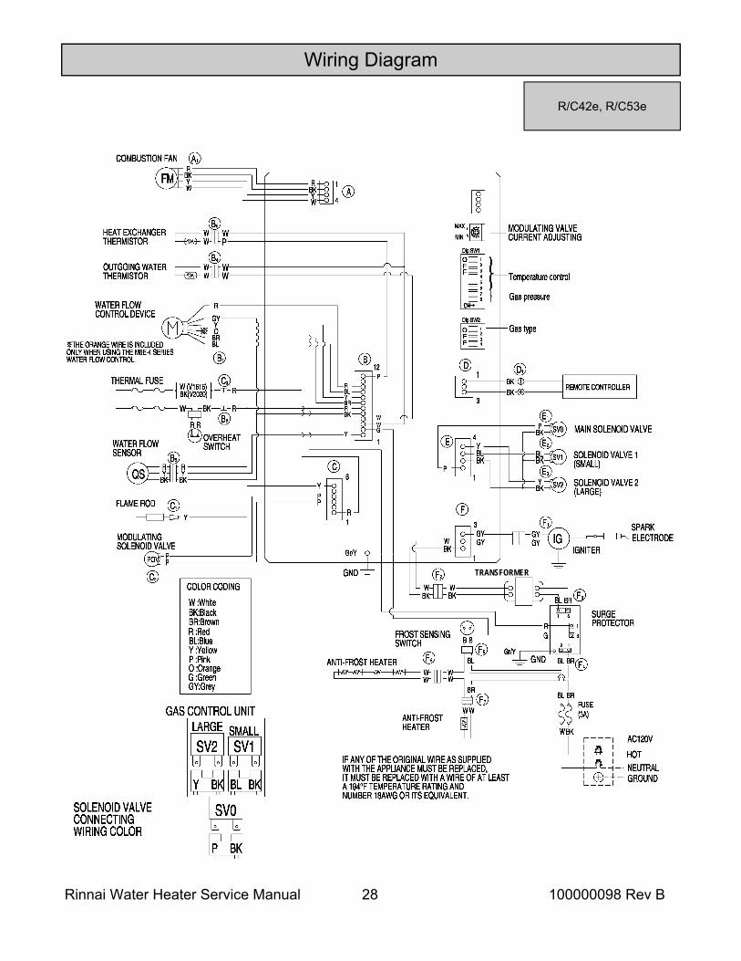
Wiring Diagram
R/C42e, R/C53e
TRANSFORMER
Rinnai Water Heater Service Manual 29 100000098 Rev B
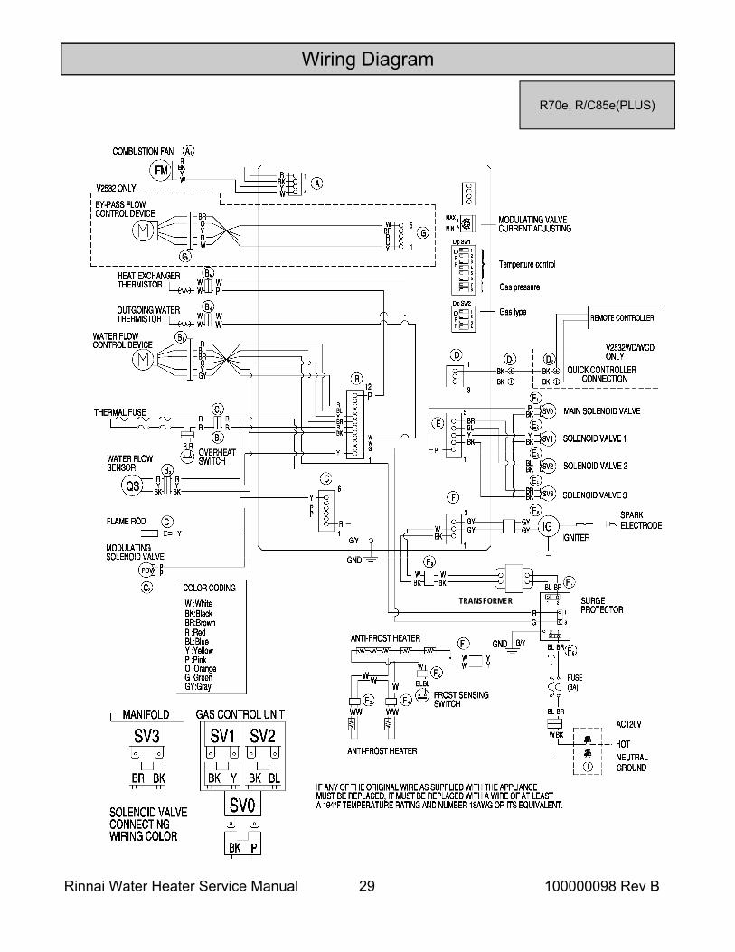
Wiring Diagram
R70e, R/C85e(PLUS)
TRANSFORMER
Rinnai Water Heater Service Manual 30 100000098 Rev B
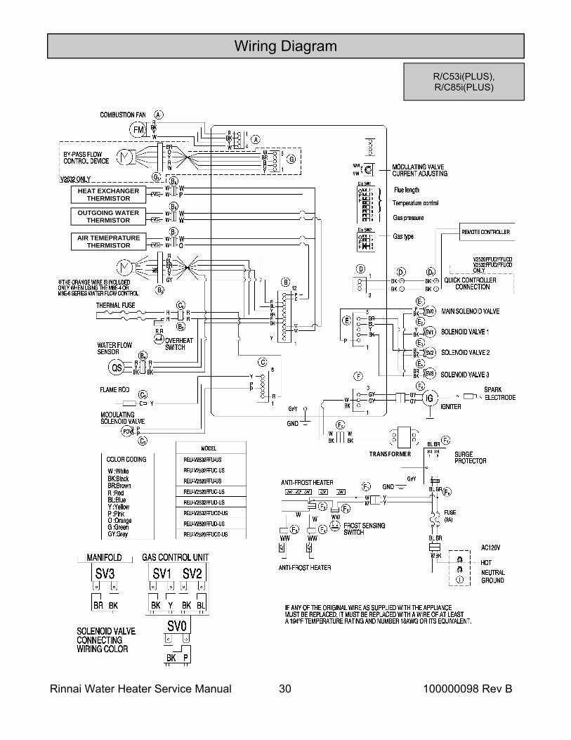
Wiring Diagram
R/C53i(PLUS), R/C85i(PLUS)
TRANSFORMER
HEAT EXCHANGER THERMISTOR
OUTGOING WATER THERMISTOR
AIR TEMEPRATURE THERMISTOR
Rinnai Water Heater Service Manual 31 100000098 Rev B
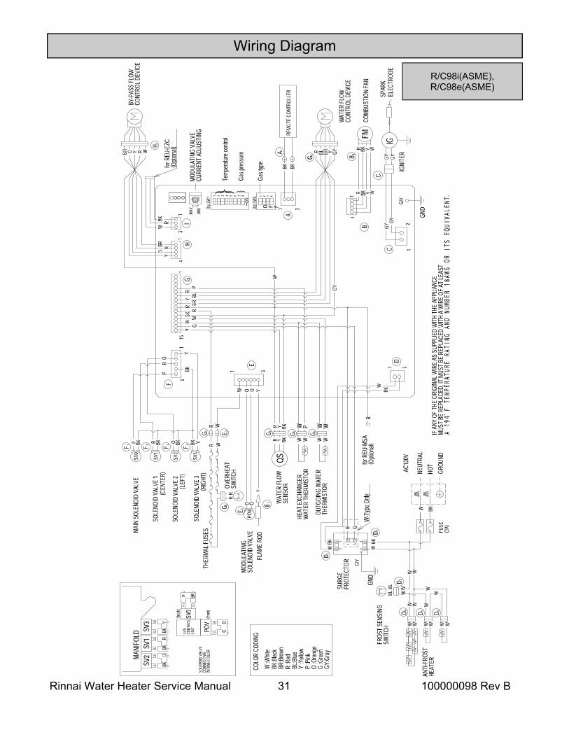
Wiring Diagram
R/C98i(ASME), R/C98e(ASME)
Rinnai Water Heater Service Manual 32 100000098 Rev B
D
C1
2B
WYBKR4
1
GYGY
D 1
FMWYBKR
B 1
IGGY GY
ELEC
TROD
ESP
ARK
IGNI
TER
COM
BUST
ION
FAN
REMO
TE C
ONTR
OLLE
RA 1
BK BK
MOD
ULAT
ING
VALV
ECU
RREN
T AD
JUST
ING
Gas p
ress
ure
3
MAX
A
1 2
Dip
SW1 3 87654 1 2 3 4
O F FDip
SW2
MIN
113
E
WBK
WY
RBRY
BLR P
1F
12
14
BLBR
(CN1
0)
(CN5
)
(CN3
)
(CN4
)
(CN2
)
(CN1
)
RP P
YP
BLBKY
THER
MAL
FUS
ESRBL
WR
OVER
HEAT
SWIT
CHF 2
F 1
MOD
ULAT
ING
SOLE
NOID
VAL
VEPO
VF 3
PP
F 4Y
FLAM
E RO
D
F 5
SV1
F 7F 6SV
0
Y BKSV
2
BKP BL BK
MAI
N SO
LENO
ID V
ALVE
SOLE
NOID
VAL
VE 1
SOLE
NOID
VAL
VE 2
(SM
ALL)
(LAR
GE)
SURG
EPR
OTEC
TOR
31
BRBL
G/Y
C 2 WBK13
GND
FUSE
(3A)
BKW
W W
C 5 W W
ANTI
-FRO
ST H
EATE
RBL
BLC 3
FROS
T SE
NSIN
GSW
ITCH
W W
WW
C 4
ANTI
-FRO
ST H
EATE
R
E 2YR BK
R Y BK
E 4W W
E 3W W
W P WWOU
TGOI
NG W
ATER
THER
MIS
TOR
HEAT
EXC
HANG
EROU
TGOI
NG W
ATER
THER
MIS
TORQS
WAT
ER F
LOW
SENS
OR
E 5
BLR BRYGY
WAT
ER F
LOW
CONT
ROL
DEVI
CE
R BL BR Y GY
GG R
FREE
ZE P
ROTE
CTIO
N
OPT
ION
V021CAV021CA HO
TNE
UTRA
LHO
TNE
UTRA
LGR
OUND
COLO
R CO
DING
COLO
R CO
DING
G/Y
C 1
E 1
5 6
GND
Spar
e Pa
rts O
nly
R :R
edO
:Ora
nge
Y :Y
ellow
G :G
reen
BL:B
lueGY
:Gre
yW
:Whit
eP
:Pink
BK:B
lack
BR:B
rown
E 6
GND
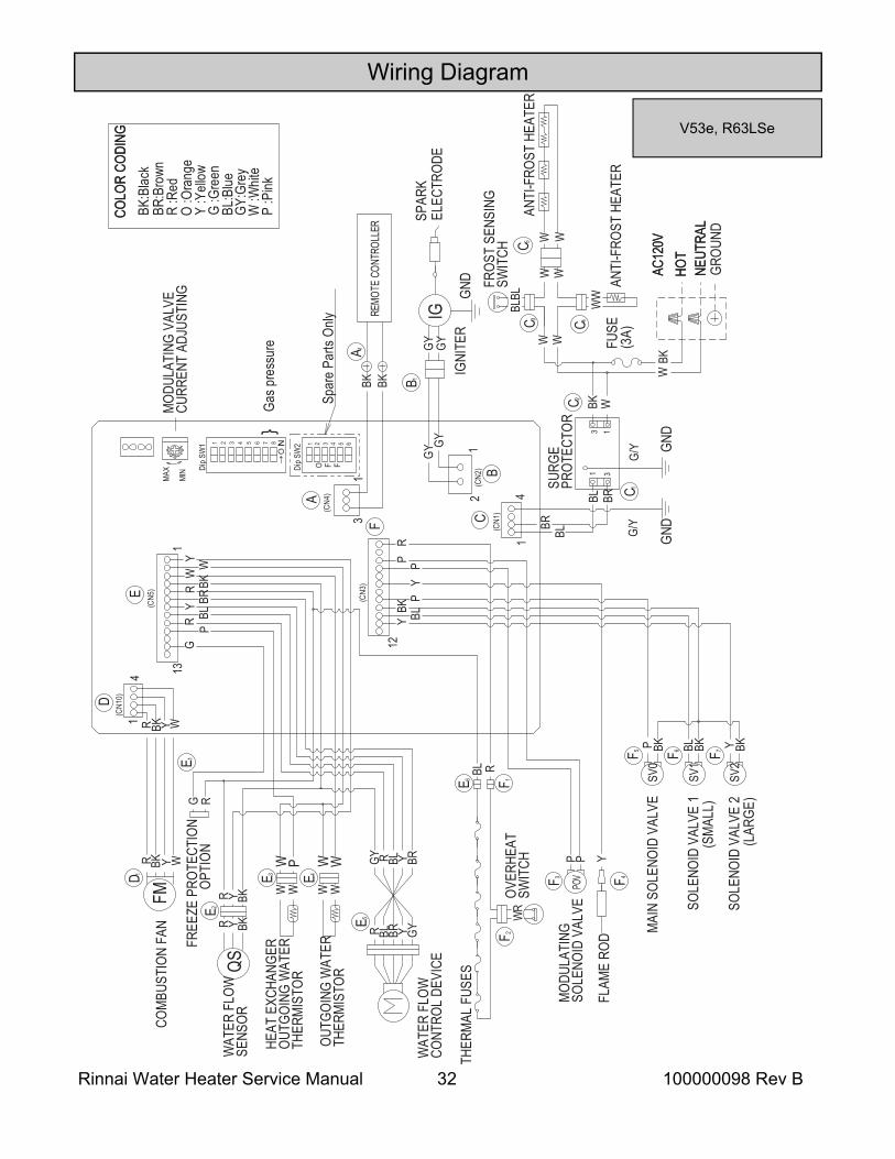
V53e, R63LSe
Wiring Diagram
Rinnai Water Heater Service Manual 33 100000098 Rev B
Wiring Diagram
COLOR CODING
W :WhiteBK:BlackBR:BrownR :RedBL:BlueY :YellowP :PinkO :OrangeG :GreenGY:Gray
1
3
BR
3
1
B
12O
FF
Dip SW1
3
87654
F 5
WW
B1
BKBK
MIN
MAX MODULATING VALVECURRENT ADJUSTING
Gas pressureF 4
WW
WP
WWOUTGOING WATER
THERMISTOR
HEAT EXCHANGERTHERMISTOR
Y
BRO
RW
BRROYW
BKRW
for REU-EZC(Optional)
1
13
WATER FLOWSENSOR
BK
F2
YRR
YBKQS
BY-PASS FLOWCONTROL DEVICE
YBKR
FREEZE PROTECTION OPTION
G
WW W
O
F 3
WW
O
P
BLR
BRY
GY
WATER FLOWCONTROL DEVICE
RBLBRY
GY
GR
AIR TEMPERATURETHERMISTOR
R
BL BR
Y
INDOOR MODEL ONLY
COMBUSTION FAN
FMR
BKYWE1
W
4 1
YBK R
BY-PASS SERVO MODEL ONLY
1
1
THERMAL FUSES
RR
OVERHEATSWITCH
H2 H1
MODULATINGSOLENOID VALVE POV
H3
PP
H4
YFLAME ROD
H5
SV1
H7
H6
SV0
BLBKSV2
BKP
YBK
MAIN SOLENOID VALVE
SOLENOID VALVE 1
SOLENOID VALVE 2
F 6
YBRBLBKP
P
(CN2)
YPR
12 1
SOLENOID VALVE 3H8
BRBKSV3
GY
C1
IGGYGY
IGNITER GND
GY
SURGEPROTECTOR
3
1
BRBL
G/Y
D2
WBK
1
3
GND
FUSE(3A)
BKW
W
BLBL D4
ANTI-FROST HEATER
AC120VAC120VHOTNEUTRALHOTNEUTRALGROUND
G/Y D1
GND
D5
ANTI-FROST HEATER
BLBL
D3
FROST SENSINGSWITCH
W
BL
REMOTE CONTROLLER
SPARKELECTRODE
54 Spare Parts Only
Gas type123O
FF
Dip SW2
6
A
C
D
E
F
G
H
F 1
G1
(CN3)
(CN4)
(CN1)
(CN12)
(CN5)
(CN7)
(CN9)
5
3
RR
F 7
(W) (W)
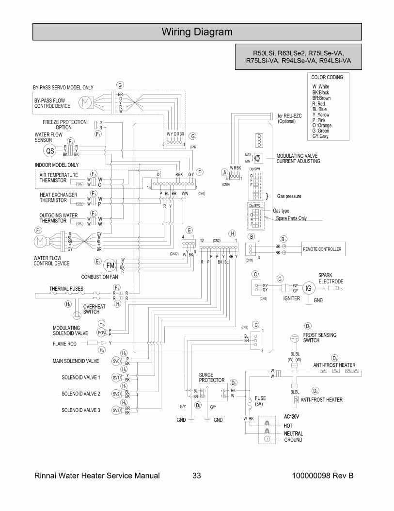
R50LSi, R63LSe2, R75LSe-VA, R75LSi-VA, R94LSe-VA, R94LSi-VA
Rinnai Water Heater Service Manual 34 100000098 Rev B
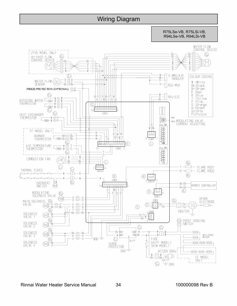
Wiring Diagram
R75LSe-VB, R75LSi-VB, R94LSe-VB, R94LSi-VB
FREEZE PROTECTION (OPTIONAL)
Rinnai Water Heater Service Manual 35 100000098 Rev B
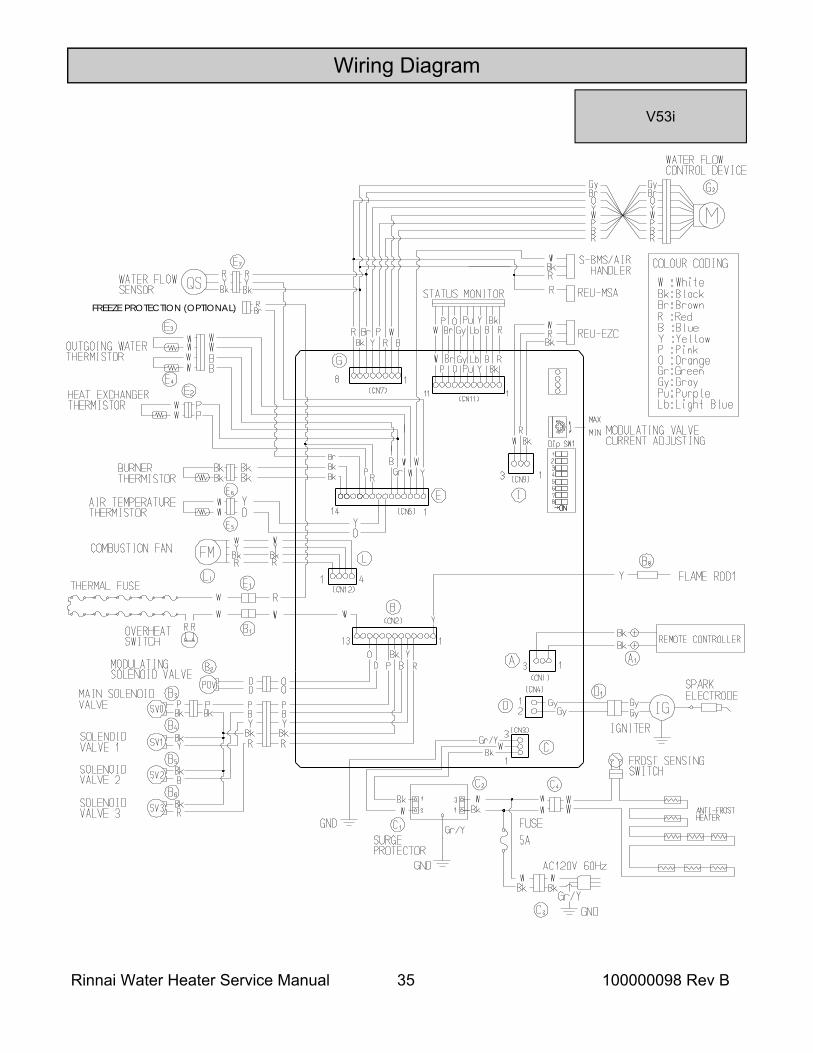
Wiring Diagram
V53i
FREEZE PROTECTION (OPTIONAL)
Rinnai Water Heater Service Manual 36 100000098 Rev B
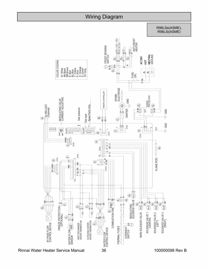
Wiring Diagram
R98LSe(ASME), R98LSi(ASME)
A
3 1
W 31
B
1 2O F FDi
p SW
1 3 87654
F 4W W
B 1BK BK
MIN
MAX
MOD
ULAT
ING
VALV
ECU
RREN
T AD
JUST
ING
Gas p
ress
ure
F 3W W
W P WWOU
TGOI
NG W
ATER
WAT
ER T
HERM
ISTO
R
HEAT
EXC
HANG
ERW
ATER
THE
RMIS
TOR
YBR O R WBRROYW
BKRW
for R
EU-E
ZC(O
ption
al)
1
13
WAT
ER F
LOW
SENS
ORBK
F 2YR
R Y BKQS
BY-P
ASS
FLOW
CONT
ROL
DEVI
CE
YBKR
FREE
ZE P
ROTE
CTIO
N
(O
PTIO
NAL)
G
WWP
BLR BRYGY
WAT
ER F
LOW
CONT
ROL
DEVI
CE
R BL BR Y GY
G R
RBLBR Y
COM
BUST
ION
FAN
FMRBKYW
E 1W4
1
Y BKR1
1
MOD
ULAT
ING
SOLE
NOID
VAL
VEPO
VH 2
OO
H 7Y
FLAM
E RO
D
H 3
SV1
H 5H 4SV
0
O BKSV
2
BKP R BK
MAI
N SO
LENO
ID V
ALVE
SOLE
NOID
VAL
VE 1
(CE
NTER
)
SOLE
NOID
VAL
VE 2
(L
EFT)
YY O
BKOO(C
N2) R
PW12
1
SOLE
NOID
VAL
VE 3
(R
IGHT
)
H 6Y BK
SV3
GY
C 1
IGGY GY
IGNI
TER
GND
GY
FUSE
(3A)
BKW
AC12
0VAC
120V
HOT
NEUT
RAL
HOT
NEUT
RAL
GROU
ND
GND
BK
REMO
TE C
ONTR
OLLE
R
SPAR
KEL
ECTR
ODE
54Sp
are
Parts
Only
Gas t
ype
1 2 3O F FDi
p SW
2 6
C D
E
F
G
H
F 1
G 1
(CN3
)
(CN4
)
(CN1
)(C
N12)
(CN5
)
(CN7
)
(CN9
)
5
3
D 2 D 1
1
WBK
WBK
G/Y
SURG
EPR
OTEC
TOR
GND
R W
RR
H 1F 6TH
ERM
AL F
USES
OVER
HEAT
SWIT
CH
R W
COLO
R CO
DING
W :W
hite
BK:B
lack
BR:B
rown
R :R
edBL
:Blue
Y :Y
ellow
P :P
inkO
:Ora
nge
G :G
reen
GY:G
ray BL
BL W
WWWW
W
ANTI
-FRO
STHE
ATER
D 5
D 3
FROS
T SE
NSIN
GSW
ITCH
W W
D 6W
WD 4
WW W
W W
1
F 5
A 1
1
G/Y
Rinnai Water Heater Service Manual 37 100000098 Rev B
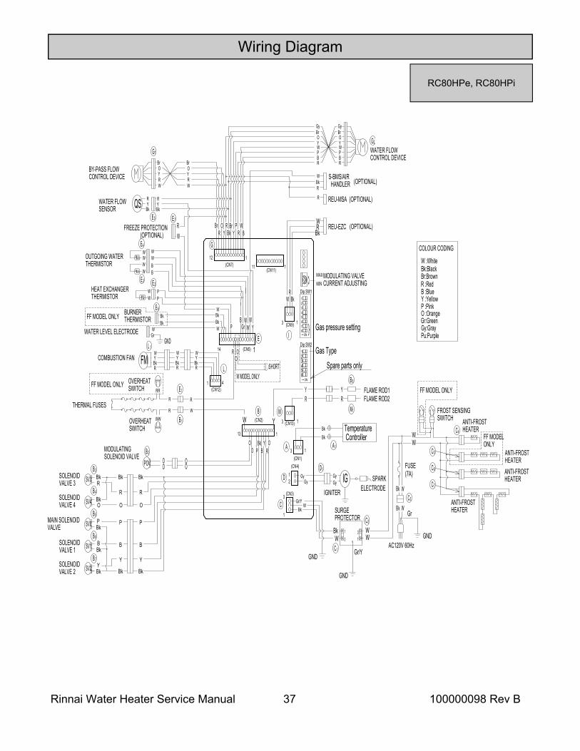
Wiring Diagram
RC80HPe, RC80HPi
21D
RBkYW
41
GyGy
L
L 1
FMR
BkYW
D1
IGGyGy
ELECTRODESPARK
IGNITER
Y
BrO
RW
BY-PASS FLOWCONTROL DEVICE
COMBUSTION FAN
G1
1
EYP
R
B
G
12
(CN12)
(CN5)
(CN7)
(CN4)
BkRO R P W
R
SURGEPROTECTOR
C1
31
WBk
GND
C2
WW
GND
FUSE(7A)
WBk
AC120V 60Hz
Bk WGr
GND
C4WW
C3
C5
E5
YR
Bk
RYBk
E2WW
PP
HEAT EXCHANGERTHERMISTOR
QSWATER FLOWSENSOR
BBr
Gr
14
31
Gr/Y
1
(CN2)
13
P BY
ROO O
WB
1
WW
W
YYBr
Bk
BrOYRW
3 1(CN1)
RY
FLAME ROD2FLAME ROD1
13 (CN9)
WR
Bk
BkRW
REU-EZC
WATER FLOWCONTROL DEVICE
G2YO
W
Gy
B
Br
P
RRBPWYO
BrGy
OO O
O
3
1
C Gr/YBk
W
(CN3)
W
R
WGr
WW
WW
W BBW
OUTGOING WATERTHERMISTOR
E 3
GNDWATER LEVEL ELECTRODE
BkS-BMS/AIR HANDLERR
W
REU-MSAR
O :Orange
Pu:Purple
COLOUR CODING
W :WhiteBk:BlackBr:BrownR :RedB :BlueY :YellowP :Pink
Gr:GreenGy:Gray
Dip SW1
}
MODULATING VALVECURRENT ADJUSTING
Gas pressure setting
MAX
MIN
123
87654
→ ON
→ ON
YTemperature Controller
A1
BkBk
THERMAL FUSESR
R
OVERHEATSWITCH
MODULATINGSOLENOID VALVE
POV
E1
B 1
B 2
13 (CN13)
Dip SW2123
654
Gas TypeOO
W MODEL ONLYSHORT
FROST SENSINGSWITCH
FF MODEL ONLY
FF MODELONLY
ANTI-FROSTHEATER
ANTI-FROSTHEATERANTI-FROSTHEATER
ANTI-FROSTHEATER
A
M
I
E4
WW
RR
OVERHEATSWITCHFF MODEL ONLY
M1
B 8
C6
C7
WBk
BkBk
BkBURNERTHERMISTOR
111 (CN11)
W
RW
FREEZE PROTECTION
E6
E7
(OPTIONAL)
(OPTIONAL)
(OPTIONAL)(OPTIONAL)
FF MODEL ONLY
BkR
YW
YR
Spare parts only
O
R
Y
B
Bk
P
SV4
SV3
SV0MAIN SOLENOIDVALVE
SOLENOIDVALVE 1
SOLENOIDVALVE 2
SV1
B3
B 4
B 5
B 6
SOLENOIDVALVE 4
SV2B 7
SOLENOIDVALVE 3
Bk
O
R
Y
B
P
BkBkBkY
B
P
O
RBk
Bk
Bk
Bk
Rinnai Water Heater Service Manual 38 100000098 Rev B
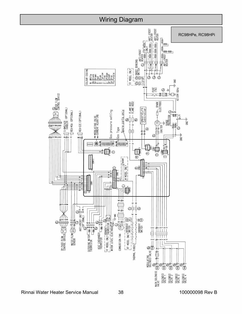
Wiring Diagram
RC98HPe, RC98HPi
Rinnai Water Heater Service Manual 39 100000098 Rev B
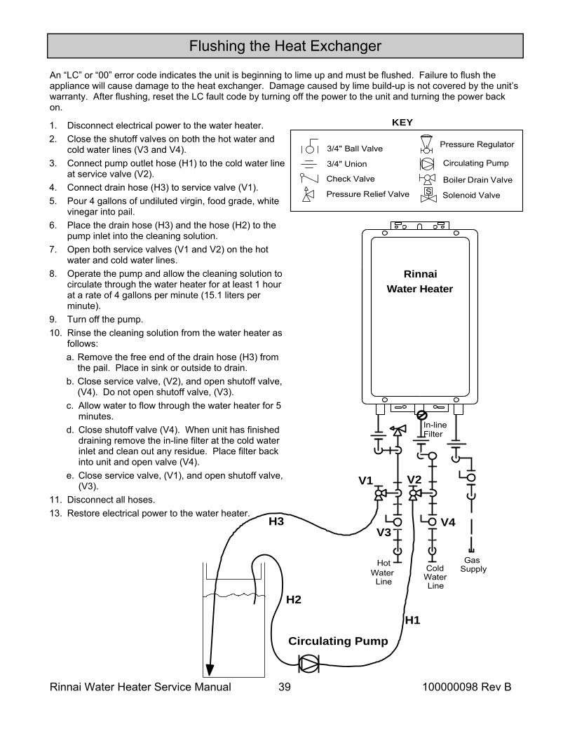
An “LC” or “00” error code indicates the unit is beginning to lime up and must be flushed. Failure to flush the appliance will cause damage to the heat exchanger. Damage caused by lime build-up is not covered by the unit’s warranty. After flushing, reset the LC fault code by turning off the power to the unit and turning the power back on.
Flushing the Heat Exchanger
Water Heater
Pressure Relief Valve
3/4" Ball Valve
3/4" Union
Check ValveS
Pressure Regulator
Circulating Pump
Solenoid Valve
Boiler Drain Valve
KEY
GasSupply
V1
V3
V2
V4
H1
H2
H3
Circulating Pump
ColdWaterLine
HotWater
Line
n-lineFilterI
Rinnai
1. Disconnect electrical power to the water heater. 2. Close the shutoff valves on both the hot water and
cold water lines (V3 and V4). 3. Connect pump outlet hose (H1) to the cold water line
at service valve (V2). 4. Connect drain hose (H3) to service valve (V1). 5. Pour 4 gallons of undiluted virgin, food grade, white
vinegar into pail. 6. Place the drain hose (H3) and the hose (H2) to the
pump inlet into the cleaning solution. 7. Open both service valves (V1 and V2) on the hot
water and cold water lines. 8. Operate the pump and allow the cleaning solution to
circulate through the water heater for at least 1 hour at a rate of 4 gallons per minute (15.1 liters per minute).
9. Turn off the pump. 10. Rinse the cleaning solution from the water heater as
follows: a. Remove the free end of the drain hose (H3) from
the pail. Place in sink or outside to drain. b. Close service valve, (V2), and open shutoff valve,
(V4). Do not open shutoff valve, (V3). c. Allow water to flow through the water heater for 5
minutes. d. Close shutoff valve (V4). When unit has finished
draining remove the in-line filter at the cold water inlet and clean out any residue. Place filter back into unit and open valve (V4).
e. Close service valve, (V1), and open shutoff valve, (V3).
11. Disconnect all hoses. 13. Restore electrical power to the water heater.
Rinnai Water Heater Service Manual 40 100000098 Rev B
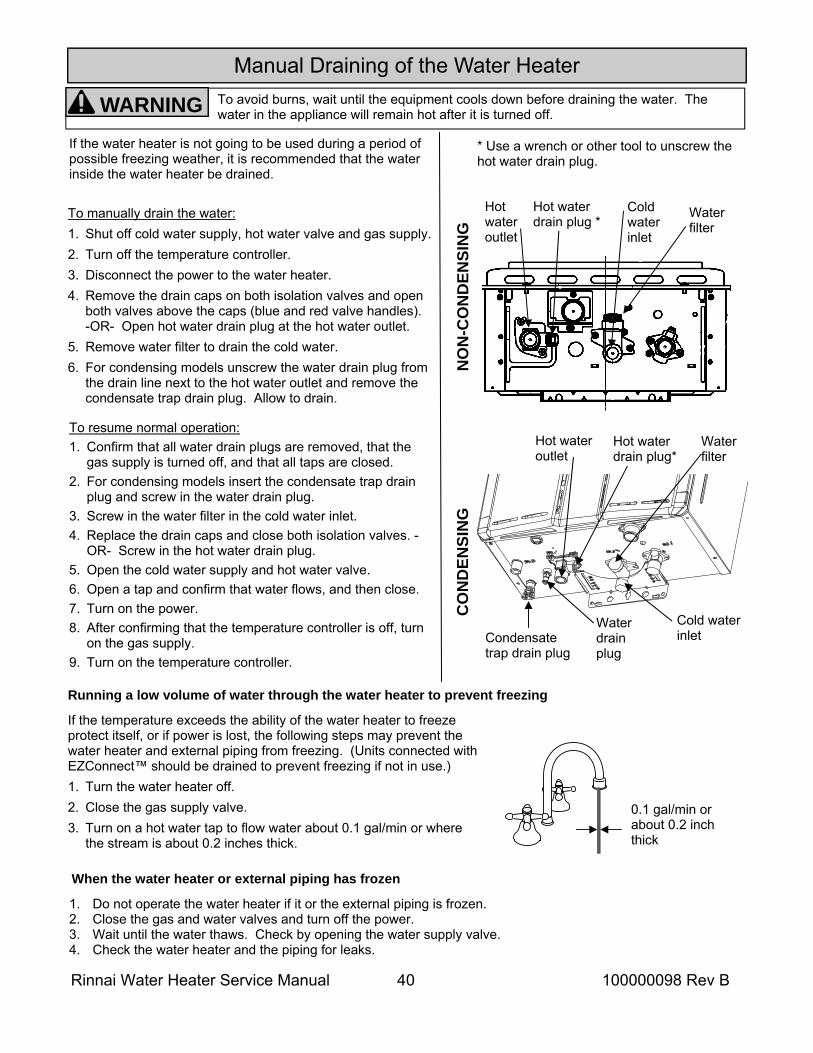
Water filter
Hot water outlet
Hot water drain plug *
Cold water inlet
If the water heater is not going to be used during a period of possible freezing weather, it is recommended that the water inside the water heater be drained.
To manually drain the water: 1. Shut off cold water supply, hot water valve and gas supply. 2. Turn off the temperature controller. 3. Disconnect the power to the water heater. 4. Remove the drain caps on both isolation valves and open
both valves above the caps (blue and red valve handles). -OR- Open hot water drain plug at the hot water outlet.
5. Remove water filter to drain the cold water. 6. For condensing models unscrew the water drain plug from
the drain line next to the hot water outlet and remove the condensate trap drain plug. Allow to drain.
To resume normal operation: 1. Confirm that all water drain plugs are removed, that the
gas supply is turned off, and that all taps are closed. 2. For condensing models insert the condensate trap drain
plug and screw in the water drain plug. 3. Screw in the water filter in the cold water inlet. 4. Replace the drain caps and close both isolation valves. -
OR- Screw in the hot water drain plug. 5. Open the cold water supply and hot water valve. 6. Open a tap and confirm that water flows, and then close. 7. Turn on the power. 8. After confirming that the temperature controller is off, turn
on the gas supply. 9. Turn on the temperature controller.
Running a low volume of water through the water heater to prevent freezing
If the temperature exceeds the ability of the water heater to freeze protect itself, or if power is lost, the following steps may prevent the water heater and external piping from freezing. (Units connected with EZConnect™ should be drained to prevent freezing if not in use.) 1. Turn the water heater off. 2. Close the gas supply valve. 3. Turn on a hot water tap to flow water about 0.1 gal/min or where
the stream is about 0.2 inches thick.
When the water heater or external piping has frozen
1. Do not operate the water heater if it or the external piping is frozen. 2. Close the gas and water valves and turn off the power. 3. Wait until the water thaws. Check by opening the water supply valve. 4. Check the water heater and the piping for leaks.
HOT
COLDON!
0.1 gal/min or about 0.2 inch thick
To avoid burns, wait until the equipment cools down before draining the water. The water in the appliance will remain hot after it is turned off. WARNING
* Use a wrench or other tool to unscrew the hot water drain plug.
Water filter
Condensate trap drain plug
Hot water outlet
Hot water drain plug*
Cold water inlet
Water drain plug
NO
N-C
ON
DEN
SIN
G
CO
ND
ENSI
NG
Manual Draining of the Water Heater
Rinnai Water Heater Service Manual 41 100000098 Rev B
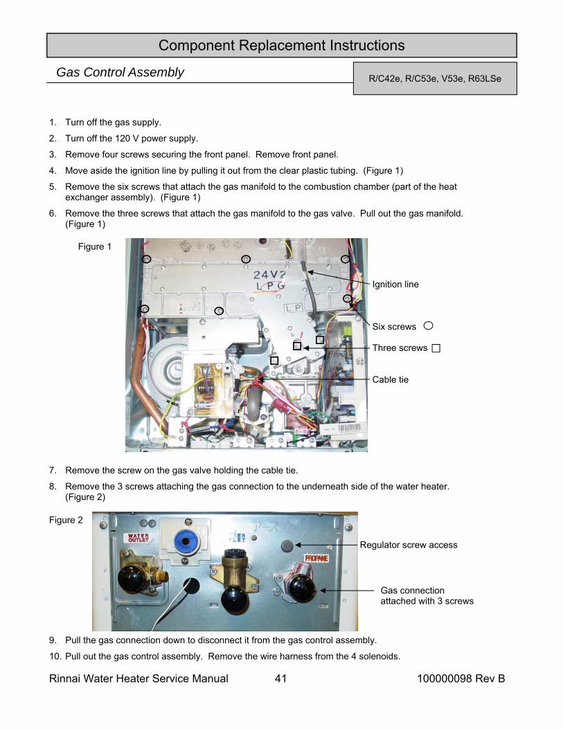
R/C42e, R/C53e, V53e, R63LSe Gas Control Assembly
Component Replacement Instructions
Ignition line Six screws Three screws Cable tie
1. Turn off the gas supply.
2. Turn off the 120 V power supply.
3. Remove four screws securing the front panel. Remove front panel.
4. Move aside the ignition line by pulling it out from the clear plastic tubing. (Figure 1)
5. Remove the six screws that attach the gas manifold to the combustion chamber (part of the heat exchanger assembly). (Figure 1)
6. Remove the three screws that attach the gas manifold to the gas valve. Pull out the gas manifold. (Figure 1)
Figure 1
7. Remove the screw on the gas valve holding the cable tie.
8. Remove the 3 screws attaching the gas connection to the underneath side of the water heater. (Figure 2)
Figure 2
Gas connection attached with 3 screws
Regulator screw access
9. Pull the gas connection down to disconnect it from the gas control assembly.
10. Pull out the gas control assembly. Remove the wire harness from the 4 solenoids.
Rinnai Water Heater Service Manual 42 100000098 Rev B
Component Replacement Instructions
Figure 4
Circular gaskets
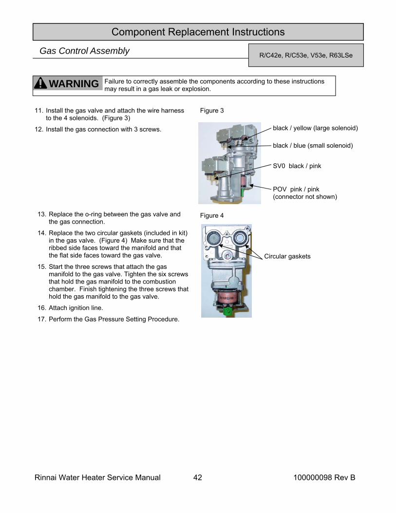
black / blue (small solenoid)
black / yellow (large solenoid)
SV0 black / pink
POV pink / pink (connector not shown)
Figure 3
WARNING Failure to correctly assemble the components according to these instructions may result in a gas leak or explosion.
11. Install the gas valve and attach the wire harness to the 4 solenoids. (Figure 3)
12. Install the gas connection with 3 screws.
13. Replace the o-ring between the gas valve and the gas connection.
14. Replace the two circular gaskets (included in kit) in the gas valve. (Figure 4) Make sure that the ribbed side faces toward the manifold and that the flat side faces toward the gas valve.
15. Start the three screws that attach the gas manifold to the gas valve. Tighten the six screws that hold the gas manifold to the combustion chamber. Finish tightening the three screws that hold the gas manifold to the gas valve.
16. Attach ignition line.
17. Perform the Gas Pressure Setting Procedure.
R/C42e, R/C53e, V53e, R63LSe Gas Control Assembly
Rinnai Water Heater Service Manual 43 100000098 Rev B
Component Replacement Instructions
Ignition line Six screws Wire harness connector PC Board (dip switches) Three screws
1. Turn off the gas supply.
2. Turn off the 120 V power supply.
3. Remove four screws securing the front panel. Remove front panel.
4. Indoor models only: Remove the temperature controller and bracket by sliding up and out of the slots. On the V53i remove the status monitor from the bottom of the manifold (one screw).
5. Pull out wire harness connector at the gas manifold assembly. See Figure 1.
6. Move aside the ignition line by pulling it out from the clear plastic tubing.
7. Remove the six screws that attach the gas manifold to the combustion chamber (part of the heat exchanger assembly).
8. Remove the three screws that attach the gas manifold to the gas valve. Pull out the gas manifold.
Figure 1
9. Remove the four screws attaching the gas connection to the underneath side of the water heater. Figure 2.
Figure 2 Gas connection attached with 4 screws
Regulator screw access
10. Pull the gas connection down to disconnect it from the gas control assembly.
11. Pull out the gas control assembly. Remove the wire harness from the 4 solenoids.
12. Replace the O-ring (included in kit) where the assembly attaches to the gas connection. Make sure the old O-ring is removed and discarded. Install the new gas control assembly.
WARNING Failure to correctly assemble the components according to these instructions may result in a gas leak or explosion.
Gas Control Assembly R/C53i(PLUS), R70e, R/C85e(PLUS), R/C85i(PLUS), R50LSi, R63LSe2, V53i,
R75LSe-VA, R75LSi-VA, R94LSe-VA, R94LSi-VA
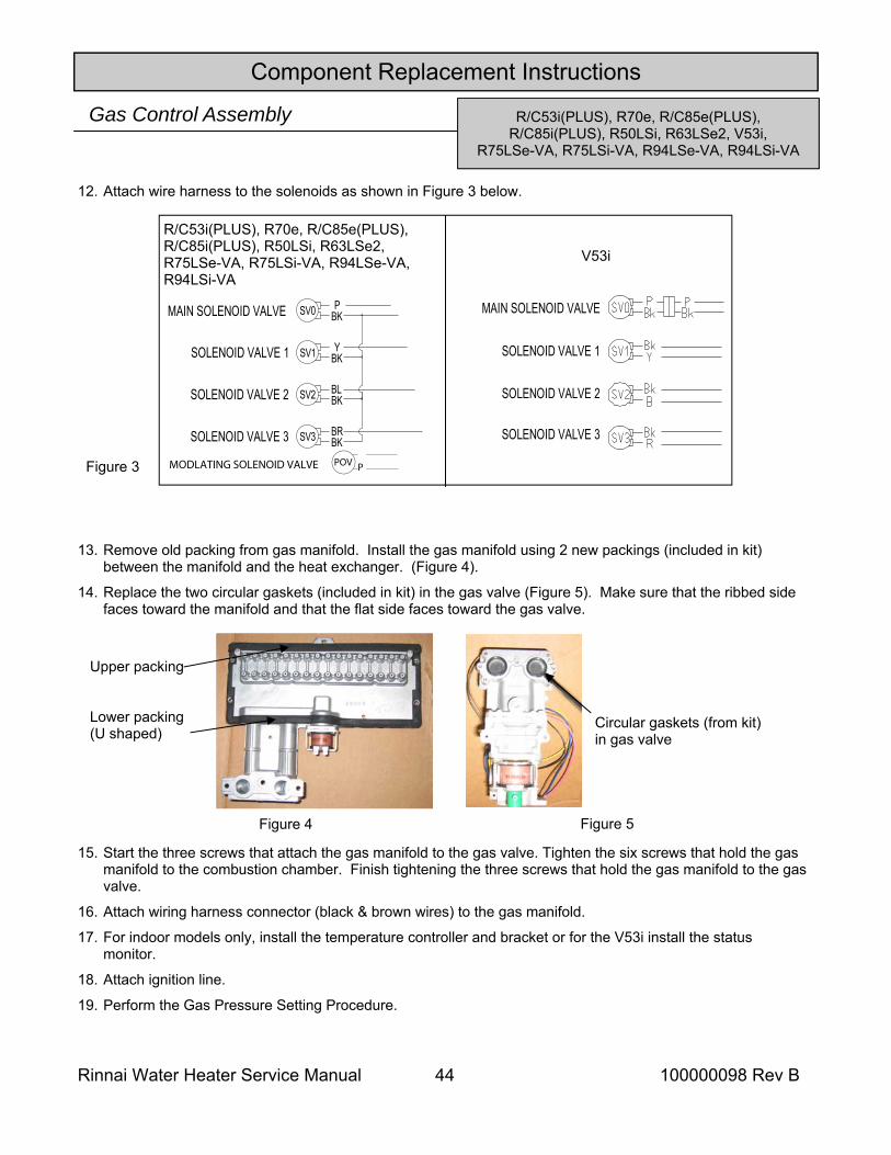
Rinnai Water Heater Service Manual 44 100000098 Rev B
Component Replacement Instructions
13. Remove old packing from gas manifold. Install the gas manifold using 2 new packings (included in kit) between the manifold and the heat exchanger. (Figure 4).
14. Replace the two circular gaskets (included in kit) in the gas valve (Figure 5). Make sure that the ribbed side faces toward the manifold and that the flat side faces toward the gas valve.
15. Start the three screws that attach the gas manifold to the gas valve. Tighten the six screws that hold the gas manifold to the combustion chamber. Finish tightening the three screws that hold the gas manifold to the gas valve.
16. Attach wiring harness connector (black & brown wires) to the gas manifold.
17. For indoor models only, install the temperature controller and bracket or for the V53i install the status monitor.
18. Attach ignition line.
19. Perform the Gas Pressure Setting Procedure.
Figure 3
12. Attach wire harness to the solenoids as shown in Figure 3 below.
Figure 4 Figure 5
Circular gaskets (from kit) in gas valve
Upper packing Lower packing (U shaped)
Gas Control Assembly
R/C53i(PLUS), R70e, R/C85e(PLUS), R/C85i(PLUS), R50LSi, R63LSe2, R75LSe-VA, R75LSi-VA, R94LSe-VA, R94LSi-VA
R/C53i(PLUS), R70e, R/C85e(PLUS), R/C85i(PLUS), R50LSi, R63LSe2, V53i,
R75LSe-VA, R75LSi-VA, R94LSe-VA, R94LSi-VA
V53i
MODLATING SOLENOID VALVE POV P
SV1
SV0
BLBKSV2
BKP
YBK
MAIN SOLENOID VALVE
SOLENOID VALVE 1
SOLENOID VALVE 2
SOLENOID VALVE 3 BRBKSV3
SOLENOID VALVE 1
SOLENOID VALVE 2
SOLENOID VALVE 3
MAIN SOLENOID VALVE
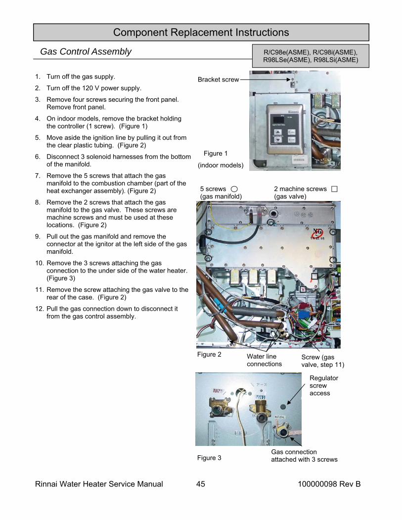
Rinnai Water Heater Service Manual 45 100000098 Rev B
Component Replacement Instructions
R/C98e(ASME), R/C98i(ASME), R98LSe(ASME), R98LSi(ASME)
Gas Control Assembly
1. Turn off the gas supply.
2. Turn off the 120 V power supply.
3. Remove four screws securing the front panel. Remove front panel.
4. On indoor models, remove the bracket holding the controller (1 screw). (Figure 1)
5. Move aside the ignition line by pulling it out from the clear plastic tubing. (Figure 2)
6. Disconnect 3 solenoid harnesses from the bottom of the manifold.
7. Remove the 5 screws that attach the gas manifold to the combustion chamber (part of the heat exchanger assembly). (Figure 2)
8. Remove the 2 screws that attach the gas manifold to the gas valve. These screws are machine screws and must be used at these locations. (Figure 2)
9. Pull out the gas manifold and remove the connector at the ignitor at the left side of the gas manifold.
10. Remove the 3 screws attaching the gas connection to the under side of the water heater. (Figure 3)
11. Remove the screw attaching the gas valve to the rear of the case. (Figure 2)
12. Pull the gas connection down to disconnect it from the gas control assembly.
Bracket screw
Figure 1
(indoor models)
Water line connections
Figure 2
5 screws (gas manifold)
2 machine screws (gas valve)
Figure 3
Regulator screw access
Gas connection attached with 3 screws
Screw (gas valve, step 11)
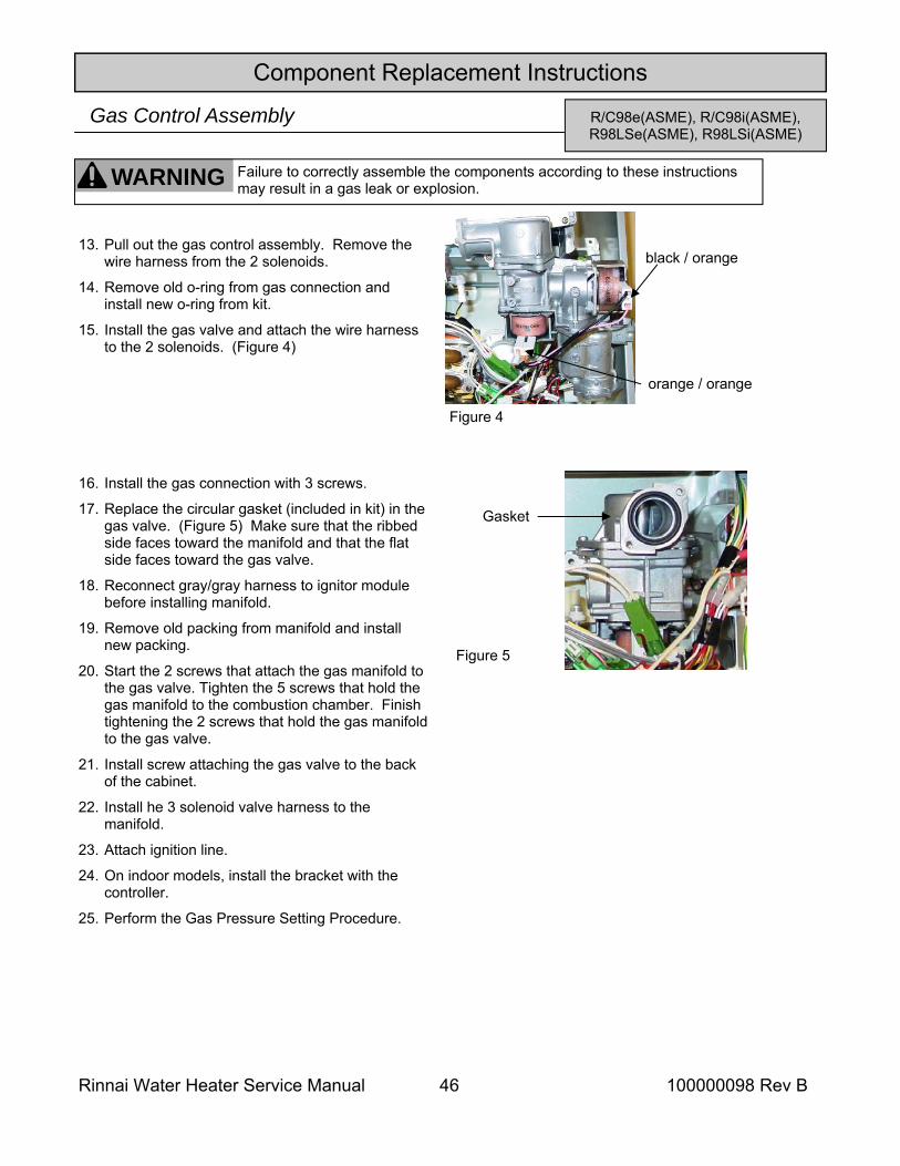
Rinnai Water Heater Service Manual 46 100000098 Rev B
Component Replacement Instructions
R/C98e(ASME), R/C98i(ASME), R98LSe(ASME), R98LSi(ASME)
Gas Control Assembly
Figure 5
black / orange
orange / orange
Figure 4
WARNING Failure to correctly assemble the components according to these instructions may result in a gas leak or explosion.
13. Pull out the gas control assembly. Remove the wire harness from the 2 solenoids.
14. Remove old o-ring from gas connection and install new o-ring from kit.
15. Install the gas valve and attach the wire harness to the 2 solenoids. (Figure 4)
16. Install the gas connection with 3 screws.
17. Replace the circular gasket (included in kit) in the gas valve. (Figure 5) Make sure that the ribbed side faces toward the manifold and that the flat side faces toward the gas valve.
18. Reconnect gray/gray harness to ignitor module before installing manifold.
19. Remove old packing from manifold and install new packing.
20. Start the 2 screws that attach the gas manifold to the gas valve. Tighten the 5 screws that hold the gas manifold to the combustion chamber. Finish tightening the 2 screws that hold the gas manifold to the gas valve.
21. Install screw attaching the gas valve to the back of the cabinet.
22. Install he 3 solenoid valve harness to the manifold.
23. Attach ignition line.
24. On indoor models, install the bracket with the controller.
25. Perform the Gas Pressure Setting Procedure.
Gasket
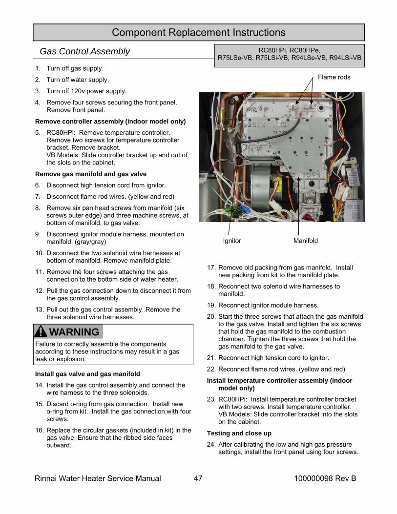
Rinnai Water Heater Service Manual 47 100000098 Rev B
Component Replacement Instructions RC80HPi, RC80HPe,
R75LSe-VB, R75LSi-VB, R94LSe-VB, R94LSi-VB Gas Control Assembly 1. Turn off gas supply.
2. Turn off water supply.
3. Turn off 120v power supply.
4. Remove four screws securing the front panel. Remove front panel.
Remove controller assembly (indoor model only) 5. RC80HPi: Remove temperature controller.
Remove two screws for temperature controller bracket. Remove bracket. VB Models: Slide controller bracket up and out of the slots on the cabinet.
Remove gas manifold and gas valve 6. Disconnect high tension cord from ignitor.
7. Disconnect flame rod wires. (yellow and red)
8. Remove six pan head screws from manifold (six screws outer edge) and three machine screws, at bottom of manifold, to gas valve.
9. Disconnect ignitor module harness, mounted on manifold. (gray/gray)
10. Disconnect the two solenoid wire harnesses at bottom of manifold. Remove manifold plate.
11. Remove the four screws attaching the gas connection to the bottom side of water heater.
12. Pull the gas connection down to disconnect it from the gas control assembly.
13. Pull out the gas control assembly. Remove the three solenoid wire harnesses.
Install gas valve and gas manifold 14. Install the gas control assembly and connect the
wire harness to the three solenoids.
15. Discard o-ring from gas connection. Install new o-ring from kit. Install the gas connection with four screws.
16. Replace the circular gaskets (included in kit) in the gas valve. Ensure that the ribbed side faces outward.
Manifold
17. Remove old packing from gas manifold. Install new packing from kit to the manifold plate.
18. Reconnect two solenoid wire harnesses to manifold.
19. Reconnect ignitor module harness.
20. Start the three screws that attach the gas manifold to the gas valve. Install and tighten the six screws that hold the gas manifold to the combustion chamber. Tighten the three screws that hold the gas manifold to the gas valve.
21. Reconnect high tension cord to ignitor.
22. Reconnect flame rod wires. (yellow and red)
Install temperature controller assembly (indoor model only)
23. RC80HPi: Install temperature controller bracket with two screws. Install temperature controller. VB Models: Slide controller bracket into the slots on the cabinet.
Testing and close up 24. After calibrating the low and high gas pressure
settings, install the front panel using four screws.
Ignitor
Flame rods
WARNING Failure to correctly assemble the components according to these instructions may result in a gas leak or explosion.
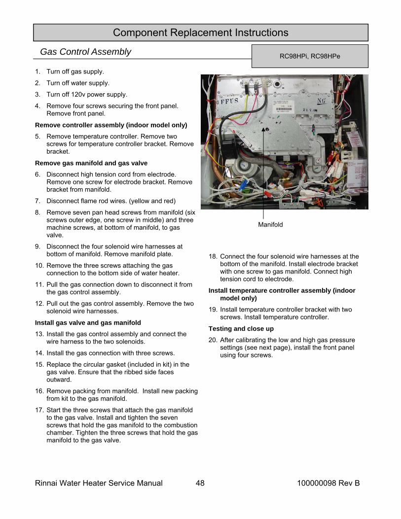
Rinnai Water Heater Service Manual 48 100000098 Rev B
Component Replacement Instructions
RC98HPi, RC98HPe Gas Control Assembly
1. Turn off gas supply.
2. Turn off water supply.
3. Turn off 120v power supply.
4. Remove four screws securing the front panel. Remove front panel.
Remove controller assembly (indoor model only) 5. Remove temperature controller. Remove two
screws for temperature controller bracket. Remove bracket.
Remove gas manifold and gas valve 6. Disconnect high tension cord from electrode.
Remove one screw for electrode bracket. Remove bracket from manifold.
7. Disconnect flame rod wires. (yellow and red)
8. Remove seven pan head screws from manifold (six screws outer edge, one screw in middle) and three machine screws, at bottom of manifold, to gas valve.
9. Disconnect the four solenoid wire harnesses at bottom of manifold. Remove manifold plate.
10. Remove the three screws attaching the gas connection to the bottom side of water heater.
11. Pull the gas connection down to disconnect it from the gas control assembly.
12. Pull out the gas control assembly. Remove the two solenoid wire harnesses.
Install gas valve and gas manifold 13. Install the gas control assembly and connect the
wire harness to the two solenoids.
14. Install the gas connection with three screws.
15. Replace the circular gasket (included in kit) in the gas valve. Ensure that the ribbed side faces outward.
16. Remove packing from manifold. Install new packing from kit to the gas manifold.
17. Start the three screws that attach the gas manifold to the gas valve. Install and tighten the seven screws that hold the gas manifold to the combustion chamber. Tighten the three screws that hold the gas manifold to the gas valve.
Manifold
18. Connect the four solenoid wire harnesses at the bottom of the manifold. Install electrode bracket with one screw to gas manifold. Connect high tension cord to electrode.
Install temperature controller assembly (indoor model only)
19. Install temperature controller bracket with two screws. Install temperature controller.
Testing and close up 20. After calibrating the low and high gas pressure
settings (see next page), install the front panel using four screws.
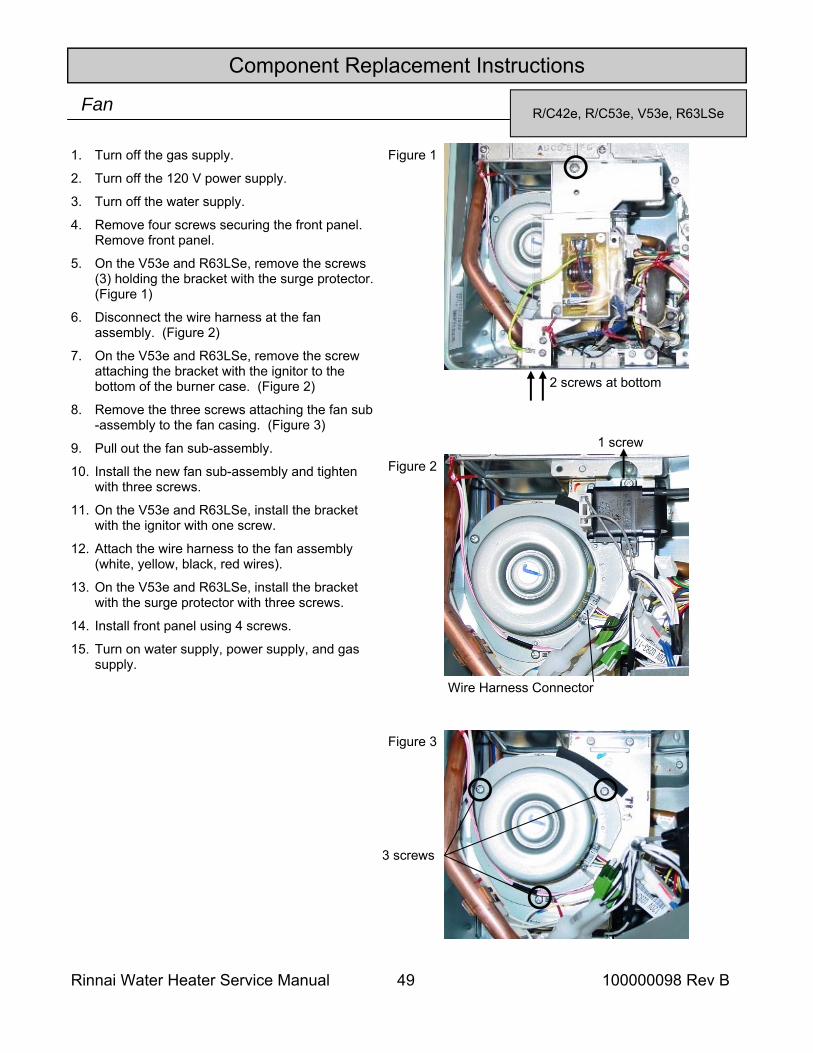
Rinnai Water Heater Service Manual 49 100000098 Rev B
Component Replacement Instructions
R/C42e, R/C53e, V53e, R63LSe Fan
1. Turn off the gas supply.
2. Turn off the 120 V power supply.
3. Turn off the water supply.
4. Remove four screws securing the front panel. Remove front panel.
5. On the V53e and R63LSe, remove the screws (3) holding the bracket with the surge protector. (Figure 1)
6. Disconnect the wire harness at the fan assembly. (Figure 2)
7. On the V53e and R63LSe, remove the screw attaching the bracket with the ignitor to the bottom of the burner case. (Figure 2)
8. Remove the three screws attaching the fan sub-assembly to the fan casing. (Figure 3)
9. Pull out the fan sub-assembly.
10. Install the new fan sub-assembly and tighten with three screws.
11. On the V53e and R63LSe, install the bracket with the ignitor with one screw.
12. Attach the wire harness to the fan assembly (white, yellow, black, red wires).
13. On the V53e and R63LSe, install the bracket with the surge protector with three screws.
14. Install front panel using 4 screws.
15. Turn on water supply, power supply, and gas supply.
Figure 1
2 screws at bottom
Figure 3
3 screws
Figure 2
1 screw
Wire Harness Connector
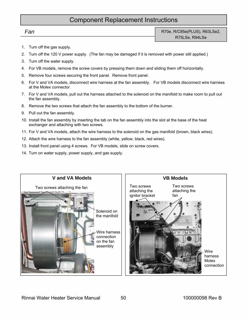
Rinnai Water Heater Service Manual 50 100000098 Rev B
Component Replacement Instructions
R70e, R/C85e(PLUS), R63LSe2, R75LSe, R94LSe
Fan
1. Turn off the gas supply.
2. Turn off the 120 V power supply. (The fan may be damaged if it is removed with power still applied.)
3. Turn off the water supply.
4. For VB models, remove the screw covers by pressing them down and sliding them off horizontally.
5. Remove four screws securing the front panel. Remove front panel.
6. For V and VA models, disconnect wire harness at the fan assembly. For VB models disconnect wire harness at the Molex connector.
7. For V and VA models, pull out the harness attached to the solenoid on the manifold to make room to pull out the fan assembly.
8. Remove the two screws that attach the fan assembly to the bottom of the burner.
9. Pull out the fan assembly.
10. Install the fan assembly by inserting the tab on the fan assembly into the slot at the base of the heat exchanger and attaching with two screws.
11. For V and VA models, attach the wire harness to the solenoid on the gas manifold (brown, black wires).
12. Attach the wire harness to the fan assembly (white, yellow, black, red wires).
13. Install front panel using 4 screws. For VB models, slide on screw covers.
14. Turn on water supply, power supply, and gas supply.
Two screws attaching the fan
Wire harness connection on the fan assembly
Solenoid on the manifold
Two screws attaching the fan
Wire harness Molex connection
Two screws attaching the ignitor bracket
V and VA Models VB Models
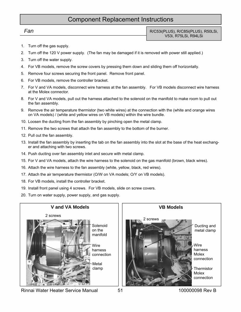
Rinnai Water Heater Service Manual 51 100000098 Rev B
Component Replacement Instructions
Fan
1. Turn off the gas supply.
2. Turn off the 120 V power supply. (The fan may be damaged if it is removed with power still applied.)
3. Turn off the water supply.
4. For VB models, remove the screw covers by pressing them down and sliding them off horizontally.
5. Remove four screws securing the front panel. Remove front panel.
6. For VB models, remove the controller bracket.
7. For V and VA models, disconnect wire harness at the fan assembly. For VB models disconnect wire harness at the Molex connector.
8. For V and VA models, pull out the harness attached to the solenoid on the manifold to make room to pull out the fan assembly.
9. Remove the air temperature thermistor (two white wires) at the connection with the (white and orange wires on VA models) / (white and yellow wires on VB models) within the wire bundle.
10. Loosen the ducting from the fan assembly by pinching open the metal clamp.
11. Remove the two screws that attach the fan assembly to the bottom of the burner.
12. Pull out the fan assembly.
13. Install the fan assembly by inserting the tab on the fan assembly into the slot at the base of the heat exchang-er and attaching with two screws.
14. Push ducting over fan assembly inlet and secure with metal clamp.
15. For V and VA models, attach the wire harness to the solenoid on the gas manifold (brown, black wires).
16. Attach the wire harness to the fan assembly (white, yellow, black, red wires).
17. Attach the air temperature thermistor (O/W on VA models; O/Y on VB models).
18. For VB models, install the controller bracket.
19. Install front panel using 4 screws. For VB models, slide on screw covers.
20. Turn on water supply, power supply, and gas supply.
2 screws
Wire harness connection
Solenoid on the manifold
Metal clamp
2 screws
Wire harness Molex connection
Thermistor Molex connection
Ducting and metal clamp
R/C53i(PLUS), R/C85i(PLUS), R50LSi, V53i, R75LSi, R94LSi
V and VA Models VB Models
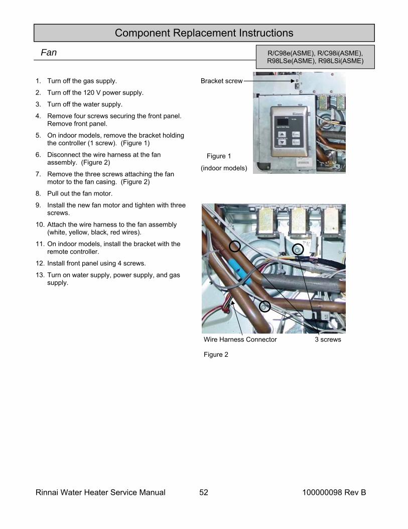
Rinnai Water Heater Service Manual 52 100000098 Rev B
Component Replacement Instructions
R/C98e(ASME), R/C98i(ASME), R98LSe(ASME), R98LSi(ASME)
Fan
1. Turn off the gas supply.
2. Turn off the 120 V power supply.
3. Turn off the water supply.
4. Remove four screws securing the front panel. Remove front panel.
5. On indoor models, remove the bracket holding the controller (1 screw). (Figure 1)
6. Disconnect the wire harness at the fan assembly. (Figure 2)
7. Remove the three screws attaching the fan motor to the fan casing. (Figure 2)
8. Pull out the fan motor.
9. Install the new fan motor and tighten with three screws.
10. Attach the wire harness to the fan assembly (white, yellow, black, red wires).
11. On indoor models, install the bracket with the remote controller.
12. Install front panel using 4 screws.
13. Turn on water supply, power supply, and gas supply.
3 screws
Figure 2
Wire Harness Connector
Bracket screw
Figure 1
(indoor models)
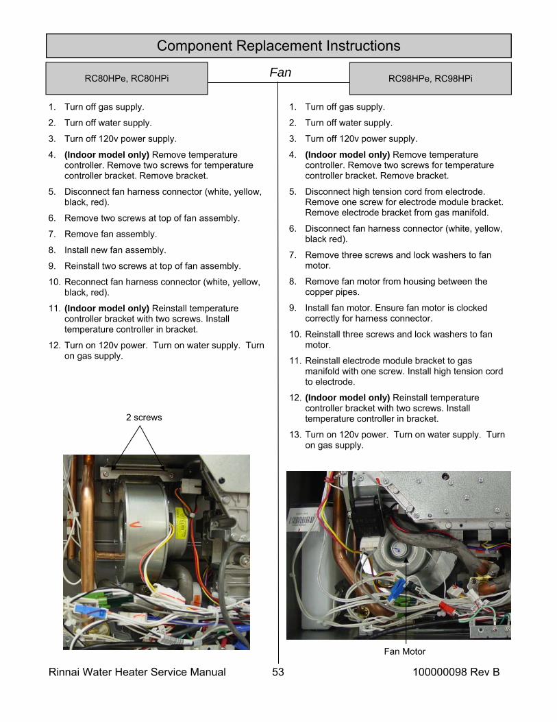
Rinnai Water Heater Service Manual 53 100000098 Rev B
Component Replacement Instructions
RC98HPe, RC98HPi Fan
1. Turn off gas supply.
2. Turn off water supply.
3. Turn off 120v power supply.
4. (Indoor model only) Remove temperature controller. Remove two screws for temperature controller bracket. Remove bracket.
5. Disconnect fan harness connector (white, yellow, black, red).
6. Remove two screws at top of fan assembly.
7. Remove fan assembly.
8. Install new fan assembly.
9. Reinstall two screws at top of fan assembly.
10. Reconnect fan harness connector (white, yellow, black, red).
11. (Indoor model only) Reinstall temperature controller bracket with two screws. Install temperature controller in bracket.
12. Turn on 120v power. Turn on water supply. Turn on gas supply.
2 screws
1. Turn off gas supply.
2. Turn off water supply.
3. Turn off 120v power supply.
4. (Indoor model only) Remove temperature controller. Remove two screws for temperature controller bracket. Remove bracket.
5. Disconnect high tension cord from electrode. Remove one screw for electrode module bracket. Remove electrode bracket from gas manifold.
6. Disconnect fan harness connector (white, yellow, black red).
7. Remove three screws and lock washers to fan motor.
8. Remove fan motor from housing between the copper pipes.
9. Install fan motor. Ensure fan motor is clocked correctly for harness connector.
10. Reinstall three screws and lock washers to fan motor.
11. Reinstall electrode module bracket to gas manifold with one screw. Install high tension cord to electrode.
12. (Indoor model only) Reinstall temperature controller bracket with two screws. Install temperature controller in bracket.
13. Turn on 120v power. Turn on water supply. Turn on gas supply.
Fan Motor
RC80HPe, RC80HPi
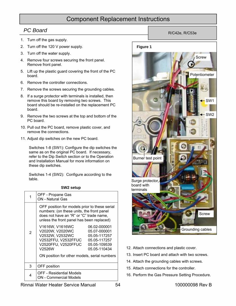
Rinnai Water Heater Service Manual 54 100000098 Rev B
Component Replacement Instructions
R/C42e, R/C53e PC Board 1. Turn off the gas supply.
2. Turn off the 120 V power supply.
3. Turn off the water supply.
4. Remove four screws securing the front panel. Remove front panel.
5. Lift up the plastic guard covering the front of the PC board.
6. Remove the controller connections.
7. Remove the screws securing the grounding cables.
8. If a surge protector with terminals is installed, then remove this board by removing two screws. This board should be re-installed on the replacement PC board.
9. Remove the two screws at the top and bottom of the PC board.
10. Pull out the PC board, remove plastic cover, and remove the connections.
11. Adjust dip switches on the new PC board.
Switches 1-8 (SW1): Configure the dip switches the same as on the original PC board. If necessary, refer to the Dip Switch section or to the Operation and Installation Manual for more information on these dip switches.
Switches 1-4 (SW2): Configure according to the table.
12. Attach connections and plastic cover.
13. Insert PC board and attach with two screws.
14. Attach the grounding cables with screws.
15. Attach connections for the controller.
16. Perform the Gas Pressure Setting Procedure.
Figure 1
SW1
SW2
Burner test point
Potentiometer
SW2 setup
OFF position for models prior to these serial numbers: (on these units, the front panel does not have an “R” or “C” trade name, unless the front panel has been replaced)
V1616W, V1616WC 06.02-000001 V2020W, V2020WC 05.07-000001 V2532W, V2532WC 05.05-117257 V2532FFU, V2532FFUC 05.05-117257 V2520FFU, V2520FFUC 05.05-109539 V2526W 05.05-110434
ON position for other models, serial numbers
1 OFF - Propane Gas ON - Natural Gas
2
3 OFF position
4 OFF - Residential Models ON - Commercial Models
Grounding cables
Screw
Screw
Surge protector board with terminals
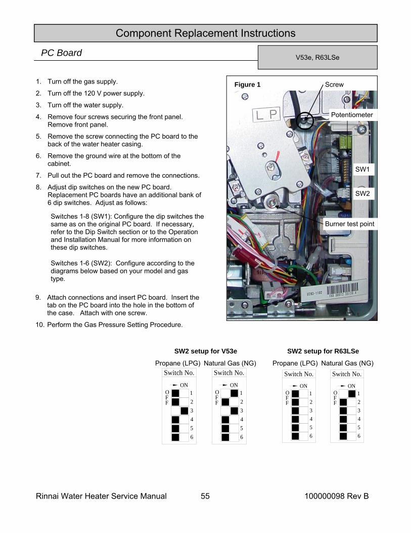
Rinnai Water Heater Service Manual 55 100000098 Rev B
Component Replacement Instructions
V53e, R63LSe PC Board
1. Turn off the gas supply.
2. Turn off the 120 V power supply.
3. Turn off the water supply.
4. Remove four screws securing the front panel. Remove front panel.
5. Remove the screw connecting the PC board to the back of the water heater casing.
6. Remove the ground wire at the bottom of the cabinet.
7. Pull out the PC board and remove the connections.
8. Adjust dip switches on the new PC board. Replacement PC boards have an additional bank of 6 dip switches. Adjust as follows:
Switches 1-8 (SW1): Configure the dip switches the same as on the original PC board. If necessary, refer to the Dip Switch section or to the Operation and Installation Manual for more information on these dip switches.
Switches 1-6 (SW2): Configure according to the diagrams below based on your model and gas type.
9. Attach connections and insert PC board. Insert the tab on the PC board into the hole in the bottom of the case. Attach with one screw.
10. Perform the Gas Pressure Setting Procedure.
Figure 1 Screw
SW1
SW2
Burner test point
Potentiometer
Switch No.
FO
F
56
43
ON12
Switch No.
FO
F
56
43
ON12
Propane (LPG) Natural Gas (NG)
SW2 setup for R63LSe
Switch No.
FO
F
56
43
ON12
Switch No.
FO
F
56
43
ON12
Propane (LPG) Natural Gas (NG)
SW2 setup for V53e
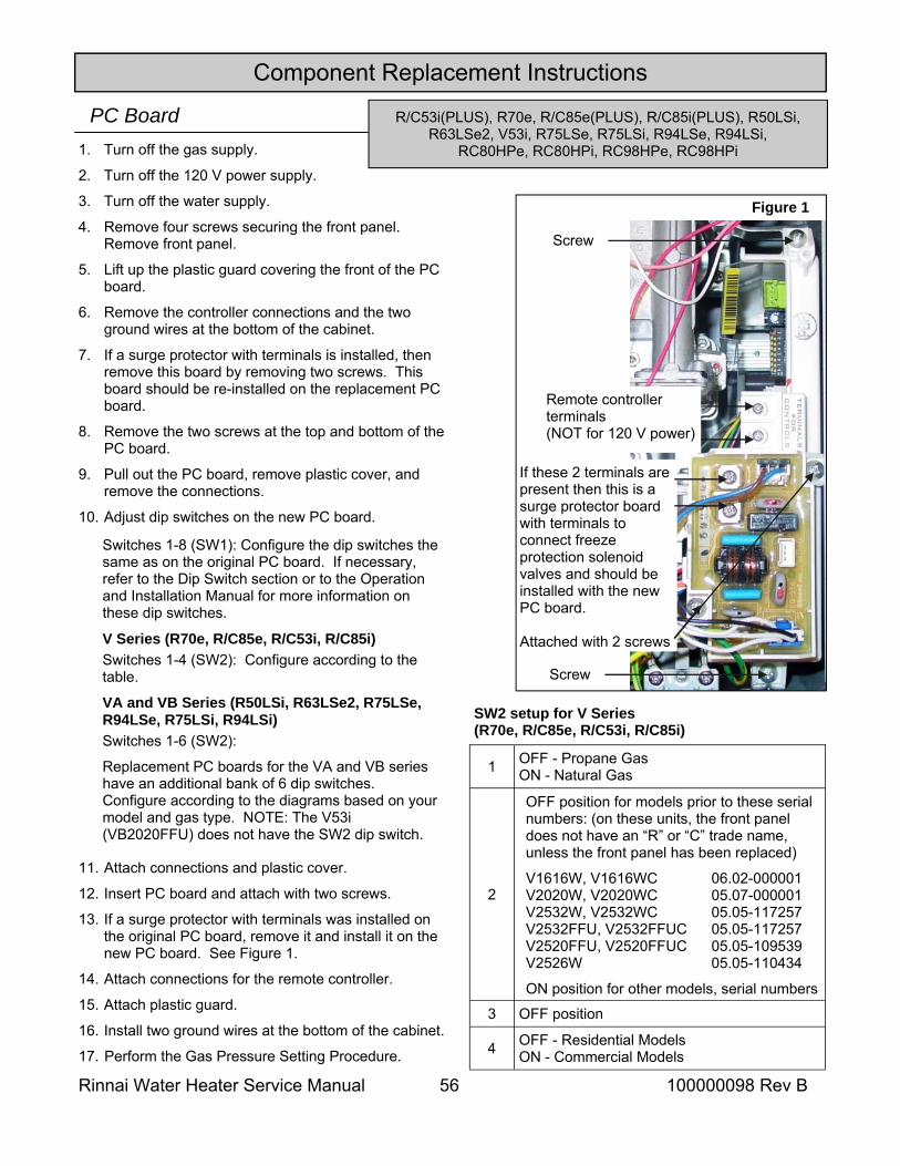
Rinnai Water Heater Service Manual 56 100000098 Rev B
1. Turn off the gas supply.
2. Turn off the 120 V power supply.
3. Turn off the water supply.
4. Remove four screws securing the front panel. Remove front panel.
5. Lift up the plastic guard covering the front of the PC board.
6. Remove the controller connections and the two ground wires at the bottom of the cabinet.
7. If a surge protector with terminals is installed, then remove this board by removing two screws. This board should be re-installed on the replacement PC board.
8. Remove the two screws at the top and bottom of the PC board.
9. Pull out the PC board, remove plastic cover, and remove the connections.
10. Adjust dip switches on the new PC board.
11. Attach connections and plastic cover.
12. Insert PC board and attach with two screws.
13. If a surge protector with terminals was installed on the original PC board, remove it and install it on the new PC board. See Figure 1.
14. Attach connections for the remote controller.
15. Attach plastic guard.
16. Install two ground wires at the bottom of the cabinet.
17. Perform the Gas Pressure Setting Procedure.
Figure 1
Screw
Screw
Remote controller terminals (NOT for 120 V power)
If these 2 terminals are present then this is a surge protector board with terminals to connect freeze protection solenoid valves and should be installed with the new PC board. Attached with 2 screws
Component Replacement Instructions
PC Board
Switches 1-8 (SW1): Configure the dip switches the same as on the original PC board. If necessary, refer to the Dip Switch section or to the Operation and Installation Manual for more information on these dip switches.
V Series (R70e, R/C85e, R/C53i, R/C85i) Switches 1-4 (SW2): Configure according to the table.
VA and VB Series (R50LSi, R63LSe2, R75LSe, R94LSe, R75LSi, R94LSi) Switches 1-6 (SW2):
Replacement PC boards for the VA and VB series have an additional bank of 6 dip switches. Configure according to the diagrams based on your model and gas type. NOTE: The V53i (VB2020FFU) does not have the SW2 dip switch.
OFF position for models prior to these serial numbers: (on these units, the front panel does not have an “R” or “C” trade name, unless the front panel has been replaced)
V1616W, V1616WC 06.02-000001 V2020W, V2020WC 05.07-000001 V2532W, V2532WC 05.05-117257 V2532FFU, V2532FFUC 05.05-117257 V2520FFU, V2520FFUC 05.05-109539 V2526W 05.05-110434
ON position for other models, serial numbers
1 OFF - Propane Gas ON - Natural Gas
2
3 OFF position
4 OFF - Residential Models ON - Commercial Models
SW2 setup for V Series (R70e, R/C85e, R/C53i, R/C85i)
R/C53i(PLUS), R70e, R/C85e(PLUS), R/C85i(PLUS), R50LSi, R63LSe2, V53i, R75LSe, R75LSi, R94LSe, R94LSi,
RC80HPe, RC80HPi, RC98HPe, RC98HPi
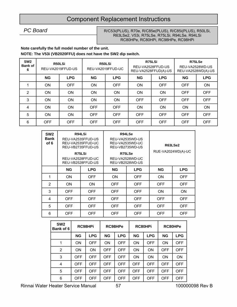
Rinnai Water Heater Service Manual 57 100000098 Rev B
Component Replacement Instructions
Note carefully the full model number of the unit. NOTE: The V53i (VB2020FFU) does not have the SW2 dip switch.
PC Board
SW2 Bank of 6
R94LSi REU-VA2535FFUD-US REU-VA2535FFUD-UC REU-VB2735FFUD-US
R75LSi REU-VA2528FFUD-UC REU-VB2528FFUD-US
R94LSe REU-VA2535WD-US REU-VA2535WD-UC REU-VB2735WD-US
R75LSe REU-VA2528WD-UC REU-VB2528WD-US
NG LPG NG LPG NG LPG
1 ON OFF ON OFF ON OFF
2 ON ON OFF OFF OFF OFF
3 OFF OFF OFF OFF ON ON
4 OFF OFF OFF OFF OFF OFF
5 OFF OFF OFF OFF OFF OFF
6 OFF OFF OFF OFF OFF OFF
R63LSe2
RUE-VA2024WD(A)-UC
SW2 Bank of
6 R50LSi
REU-VA2019FFUD-US R50LSi
REU-VA2019FFUD-UC
R75LSi REU-VA2528FFUD-US
REU-VA2528FFUD(A)-US
NG LPG NG LPG NG LPG NG LPG
1 ON OFF ON OFF ON OFF OFF ON
2 ON ON ON ON ON ON OFF OFF
3 ON ON ON ON OFF OFF OFF OFF
4 ON ON OFF OFF ON ON ON ON
5 ON ON OFF OFF OFF OFF OFF OFF
6 OFF OFF OFF OFF OFF OFF OFF OFF
R75LSe REU-VA2528WD-US
REU-VA2528WD(A)-US
SW2 Bank of 6 RC98HPi RC98HPe RC80HPi
NG LPG NG LPG NG LPG NG LPG
1 ON OFF ON OFF ON OFF ON OFF
2 ON ON OFF OFF ON ON OFF OFF
3 OFF OFF OFF OFF ON ON ON ON
4 OFF OFF OFF OFF OFF OFF OFF OFF
5 OFF OFF OFF OFF OFF OFF OFF OFF
6 OFF OFF OFF OFF OFF OFF OFF OFF
RC80HPe
R/C53i(PLUS), R70e, R/C85e(PLUS), R/C85i(PLUS), R50LSi, R63LSe2, V53i, R75LSe, R75LSi, R94LSe, R94LSi
RC80HPe, RC80HPi, RC98HPe, RC98HPi
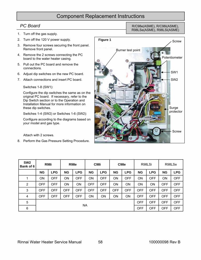
Rinnai Water Heater Service Manual 58 100000098 Rev B
Component Replacement Instructions
R/C98e(ASME), R/C98i(ASME), R98LSe(ASME), R98LSi(ASME)
PC Board 1. Turn off the gas supply.
2. Turn off the 120 V power supply.
3. Remove four screws securing the front panel. Remove front panel.
4. Remove the 2 screws connecting the PC board to the water heater casing.
5. Pull out the PC board and remove the connections.
6. Adjust dip switches on the new PC board.
7. Attach connections and insert PC board.
Attach with 2 screws.
8. Perform the Gas Pressure Setting Procedure.
Figure 1 Screw
SW1
SW2
Burner test point
Potentiometer
Surge protector
Screw
Switches 1-8 (SW1):
Configure the dip switches the same as on the original PC board. If necessary, refer to the Dip Switch section or to the Operation and Installation Manual for more information on these dip switches.
Switches 1-4 (SW2) or Switches 1-6 (SW2):
Configure according to the diagrams based on your model and gas type.
SW2 Bank of 6 R98i R98e C98i C98e R98LSi R98LSe
NG LPG NG LPG NG LPG NG LPG NG LPG NG LPG
1 ON OFF ON OFF ON OFF ON OFF ON OFF ON OFF
2 OFF OFF ON ON OFF OFF ON ON ON ON OFF OFF
3 OFF OFF OFF OFF OFF OFF OFF OFF OFF OFF OFF OFF
4 OFF OFF OFF OFF ON ON ON ON OFF OFF OFF OFF
5 OFF OFF OFF OFF
6 OFF OFF OFF OFF NA
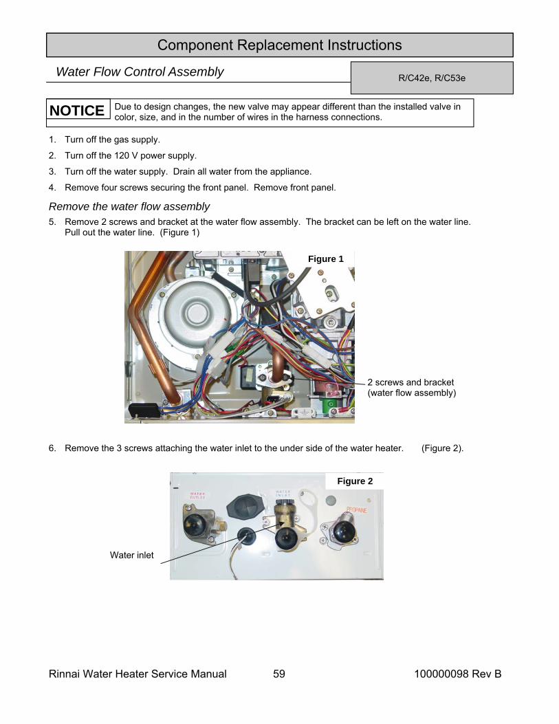
Rinnai Water Heater Service Manual 59 100000098 Rev B
Component Replacement Instructions
R/C42e, R/C53e Water Flow Control Assembly
1. Turn off the gas supply.
2. Turn off the 120 V power supply.
3. Turn off the water supply. Drain all water from the appliance.
4. Remove four screws securing the front panel. Remove front panel.
5. Remove 2 screws and bracket at the water flow assembly. The bracket can be left on the water line. Pull out the water line. (Figure 1)
6. Remove the 3 screws attaching the water inlet to the under side of the water heater. (Figure 2).
Remove the water flow assembly
Figure 1
Due to design changes, the new valve may appear different than the installed valve in color, size, and in the number of wires in the harness connections. NOTICE
Water inlet
Figure 2
2 screws and bracket (water flow assembly)
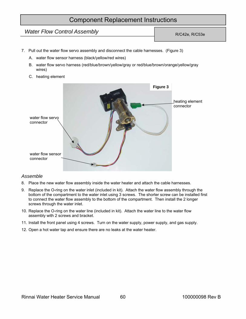
Rinnai Water Heater Service Manual 60 100000098 Rev B
R/C42e, R/C53e Water Flow Control Assembly
Component Replacement Instructions
Assemble
A. water flow sensor harness (black/yellow/red wires)
B. water flow servo harness (red/blue/brown/yellow/gray or red/blue/brown/orange/yellow/gray wires)
C. heating element
7. Pull out the water flow servo assembly and disconnect the cable harnesses. (Figure 3)
8. Place the new water flow assembly inside the water heater and attach the cable harnesses.
9. Replace the O-ring on the water inlet (included in kit). Attach the water flow assembly through the bottom of the compartment to the water inlet using 3 screws. The shorter screw can be installed first to connect the water flow assembly to the bottom of the compartment. Then install the 2 longer screws through the water inlet.
10. Replace the O-ring on the water line (included in kit). Attach the water line to the water flow assembly with 2 screws and bracket.
11. Install the front panel using 4 screws. Turn on the water supply, power supply, and gas supply.
12. Open a hot water tap and ensure there are no leaks at the water heater.
Figure 3
water flow servo connector
heating element connector
water flow sensor connector
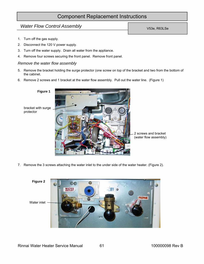
Rinnai Water Heater Service Manual 61 100000098 Rev B
Component Replacement Instructions
V53e, R63LSe Water Flow Control Assembly
1. Turn off the gas supply.
2. Disconnect the 120 V power supply.
3. Turn off the water supply. Drain all water from the appliance.
4. Remove four screws securing the front panel. Remove front panel.
5. Remove the bracket holding the surge protector (one screw on top of the bracket and two from the bottom of the cabinet.
6. Remove 2 screws and 1 bracket at the water flow assembly. Pull out the water line. (Figure 1)
7. Remove the 3 screws attaching the water inlet to the under side of the water heater. (Figure 2).
Remove the water flow assembly
Water inlet
Figure 2
Figure 1
2 screws and bracket (water flow assembly)
bracket with surge protector
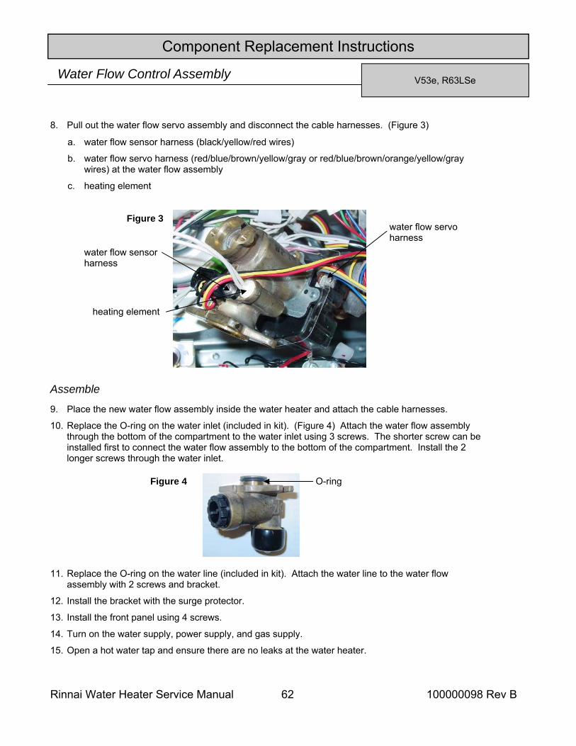
Rinnai Water Heater Service Manual 62 100000098 Rev B
Component Replacement Instructions
Assemble
a. water flow sensor harness (black/yellow/red wires)
b. water flow servo harness (red/blue/brown/yellow/gray or red/blue/brown/orange/yellow/gray wires) at the water flow assembly
c. heating element
8. Pull out the water flow servo assembly and disconnect the cable harnesses. (Figure 3)
9. Place the new water flow assembly inside the water heater and attach the cable harnesses.
10. Replace the O-ring on the water inlet (included in kit). (Figure 4) Attach the water flow assembly through the bottom of the compartment to the water inlet using 3 screws. The shorter screw can be installed first to connect the water flow assembly to the bottom of the compartment. Install the 2 longer screws through the water inlet.
11. Replace the O-ring on the water line (included in kit). Attach the water line to the water flow assembly with 2 screws and bracket.
12. Install the bracket with the surge protector.
13. Install the front panel using 4 screws.
14. Turn on the water supply, power supply, and gas supply.
15. Open a hot water tap and ensure there are no leaks at the water heater.
Figure 3
water flow sensor harness
heating element
water flow servo harness
O-ring Figure 4
V53e, R63LSe Water Flow Control Assembly
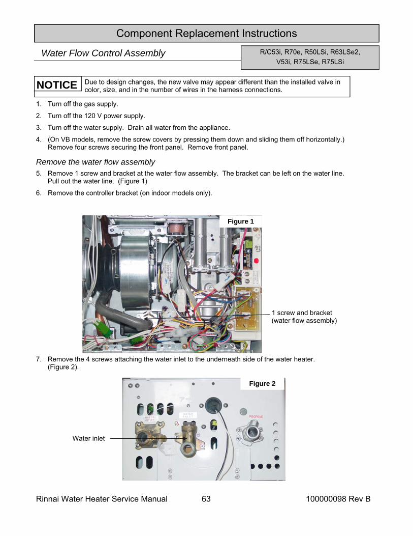
Rinnai Water Heater Service Manual 63 100000098 Rev B
Component Replacement Instructions R/C53i, R70e, R50LSi, R63LSe2,
V53i, R75LSe, R75LSi Water Flow Control Assembly
1. Turn off the gas supply.
2. Turn off the 120 V power supply.
3. Turn off the water supply. Drain all water from the appliance.
4. (On VB models, remove the screw covers by pressing them down and sliding them off horizontally.) Remove four screws securing the front panel. Remove front panel.
5. Remove 1 screw and bracket at the water flow assembly. The bracket can be left on the water line. Pull out the water line. (Figure 1)
6. Remove the controller bracket (on indoor models only).
7. Remove the 4 screws attaching the water inlet to the underneath side of the water heater. (Figure 2).
Remove the water flow assembly
Figure 1
Due to design changes, the new valve may appear different than the installed valve in color, size, and in the number of wires in the harness connections. NOTICE
Water inlet
Figure 2
1 screw and bracket (water flow assembly)
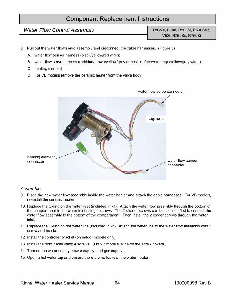
Rinnai Water Heater Service Manual 64 100000098 Rev B
Component Replacement Instructions
R/C53i, R70e, R50LSi, R63LSe2, V53i, R75LSe, R75LSi
Water Flow Control Assembly
Assemble
A. water flow sensor harness (black/yellow/red wires)
B. water flow servo harness (red/blue/brown/yellow/gray or red/blue/brown/orange/yellow/gray wires)
C. heating element
D. For VB models remove the ceramic heater from the valve body
8. Pull out the water flow servo assembly and disconnect the cable harnesses. (Figure 3)
9. Place the new water flow assembly inside the water heater and attach the cable harnesses. For VB models, re-install the ceramic heater.
10. Replace the O-ring on the water inlet (included in kit). Attach the water flow assembly through the bottom of the compartment to the water inlet using 4 screws. The 2 shorter screws can be installed first to connect the water flow assembly to the bottom of the compartment. Then install the 2 longer screws through the water inlet.
11. Replace the O-ring on the water line (included in kit). Attach the water line to the water flow assembly with 1 screw and bracket.
12. Install the controller bracket (on indoor models only).
13. Install the front panel using 4 screws. (On VB models, slide on the screw covers.)
14. Turn on the water supply, power supply, and gas supply.
15. Open a hot water tap and ensure there are no leaks at the water heater.
Figure 3
water flow servo connector
heating element connector water flow sensor
connector
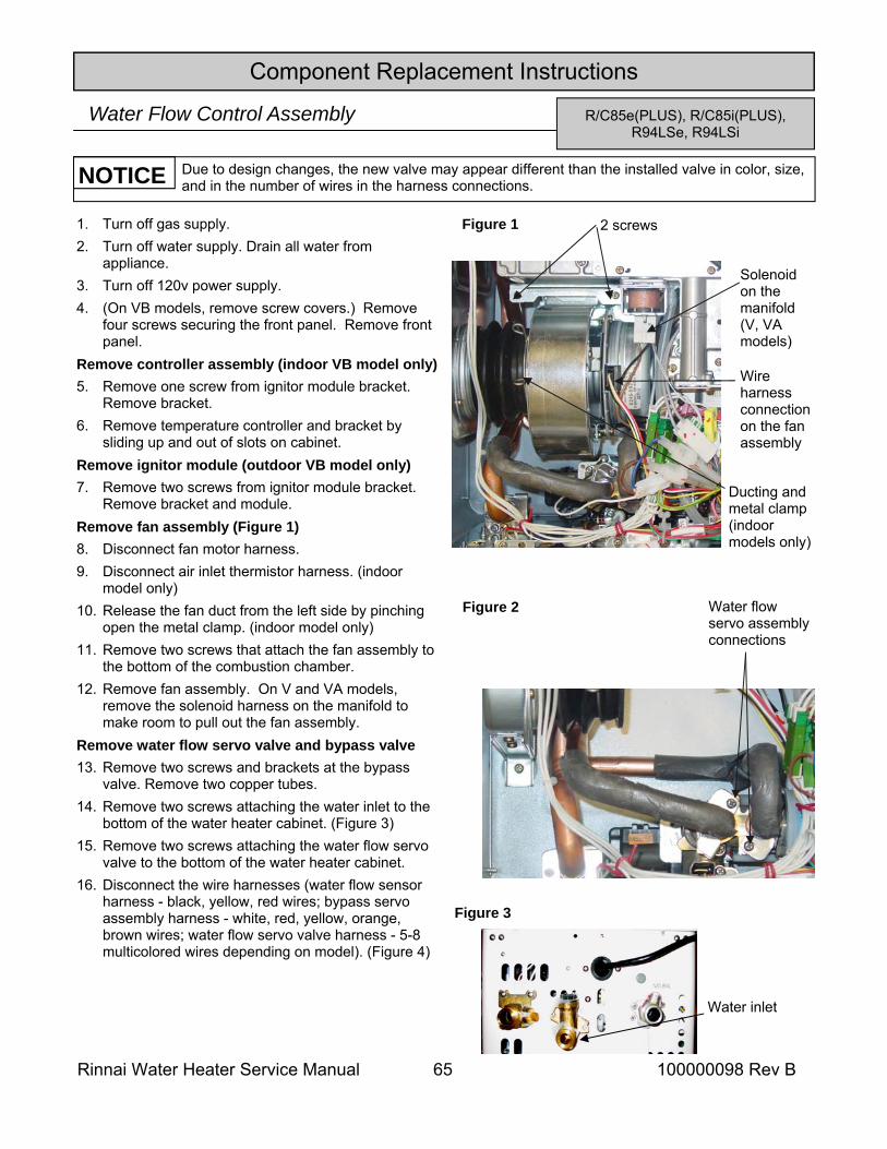
Rinnai Water Heater Service Manual 65 100000098 Rev B
Component Replacement Instructions
R/C85e(PLUS), R/C85i(PLUS), R94LSe, R94LSi
Water Flow Control Assembly
Due to design changes, the new valve may appear different than the installed valve in color, size, and in the number of wires in the harness connections. NOTICE
Water flow servo assembly connections
Figure 2
Water inlet
Figure 3
1. Turn off gas supply. 2. Turn off water supply. Drain all water from
appliance. 3. Turn off 120v power supply. 4. (On VB models, remove screw covers.) Remove
four screws securing the front panel. Remove front panel.
Remove controller assembly (indoor VB model only) 5. Remove one screw from ignitor module bracket.
Remove bracket. 6. Remove temperature controller and bracket by
sliding up and out of slots on cabinet. Remove ignitor module (outdoor VB model only) 7. Remove two screws from ignitor module bracket.
Remove bracket and module. Remove fan assembly (Figure 1) 8. Disconnect fan motor harness. 9. Disconnect air inlet thermistor harness. (indoor
model only) 10. Release the fan duct from the left side by pinching
open the metal clamp. (indoor model only) 11. Remove two screws that attach the fan assembly to
the bottom of the combustion chamber. 12. Remove fan assembly. On V and VA models,
remove the solenoid harness on the manifold to make room to pull out the fan assembly.
Remove water flow servo valve and bypass valve 13. Remove two screws and brackets at the bypass
valve. Remove two copper tubes. 14. Remove two screws attaching the water inlet to the
bottom of the water heater cabinet. (Figure 3) 15. Remove two screws attaching the water flow servo
valve to the bottom of the water heater cabinet. 16. Disconnect the wire harnesses (water flow sensor
harness - black, yellow, red wires; bypass servo assembly harness - white, red, yellow, orange, brown wires; water flow servo valve harness - 5-8 multicolored wires depending on model). (Figure 4)
2 screws
Wire harness connection on the fan assembly
Solenoid on the manifold (V, VA models)
Ducting and metal clamp (indoor models only)
Figure 1
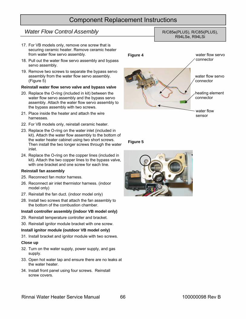
Rinnai Water Heater Service Manual 66 100000098 Rev B
Component Replacement Instructions
R/C85e(PLUS), R/C85i(PLUS), R94LSe, R94LSi
Water Flow Control Assembly
water flow servo connector
heating element connector
water flow sensor
water flow servo connector
Figure 4
17. For VB models only, remove one screw that is securing ceramic heater. Remove ceramic heater from water flow servo assembly.
18. Pull out the water flow servo assembly and bypass servo assembly.
19. Remove two screws to separate the bypass servo assembly from the water flow servo assembly. (Figure 5)
Reinstall water flow servo valve and bypass valve 20. Replace the O-ring (included in kit) between the
water flow servo assembly and the bypass servo assembly. Attach the water flow servo assembly to the bypass assembly with two screws.
21. Place inside the heater and attach the wire harnesses.
22. For VB models only, reinstall ceramic heater. 23. Replace the O-ring on the water inlet (included in
kit). Attach the water flow assembly to the bottom of the water heater cabinet using two short screws. Then install the two longer screws through the water inlet.
24. Replace the O-ring on the copper lines (included in kit). Attach the two copper lines to the bypass valve, with one bracket and one screw for each line.
Reinstall fan assembly 25. Reconnect fan motor harness. 26. Reconnect air inlet thermistor harness. (indoor
model only) 27. Reinstall the fan duct. (indoor model only) 28. Install two screws that attach the fan assembly to
the bottom of the combustion chamber. Install controller assembly (indoor VB model only) 29. Reinstall temperature controller and bracket. 30. Reinstall ignitor module bracket with one screw. Install ignitor module (outdoor VB model only) 31. Install bracket and ignitor module with two screws. Close up 32. Turn on the water supply, power supply, and gas
supply. 33. Open hot water tap and ensure there are no leaks at
the water heater. 34. Install front panel using four screws. Reinstall
screw covers.
Figure 5
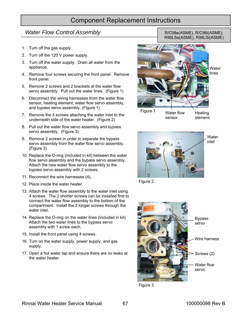
Rinnai Water Heater Service Manual 67 100000098 Rev B
Component Replacement Instructions
R/C98e(ASME), R/C98i(ASME), R98LSe(ASME), R98LSi(ASME)
Water Flow Control Assembly
1. Turn off the gas supply.
2. Turn off the 120 V power supply.
3. Turn off the water supply. Drain all water from the appliance.
4. Remove four screws securing the front panel. Remove front panel.
5. Remove 2 screws and 2 brackets at the water flow servo assembly. Pull out the water lines. (Figure 1)
6. Disconnect the wiring harnesses from the water flow sensor, heating element, water flow servo assembly, and bypass servo assembly. (Figure 1)
7. Remove the 4 screws attaching the water inlet to the underneath side of the water heater. (Figure 2)
8. Pull out the water flow servo assembly and bypass servo assembly. (Figure 3)
9. Remove 2 screws in order to separate the bypass servo assembly from the water flow servo assembly. (Figure 3)
10. Replace the O-ring (included in kit) between the water flow servo assembly and the bypass servo assembly. Attach the new water flow servo assembly to the bypass servo assembly with 2 screws.
11. Reconnect the wire harnesses (4).
12. Place inside the water heater.
13. Attach the water flow assembly to the water inlet using 4 screws. The 2 shorter screws can be installed first to connect the water flow assembly to the bottom of the compartment. Install the 2 longer screws through the water inlet.
14. Replace the O-ring on the water lines (included in kit). Attach the two water lines to the bypass servo assembly with 1 screw each.
15. Install the front panel using 4 screws.
16. Turn on the water supply, power supply, and gas supply.
17. Open a hot water tap and ensure there are no leaks at the water heater.
Figure 2
Water inlet
Figure 1
Water lines
Water flow sensor
Heating element
Figure 3
Bypass servo
Water flow servo
Screws (2)
Wire harness
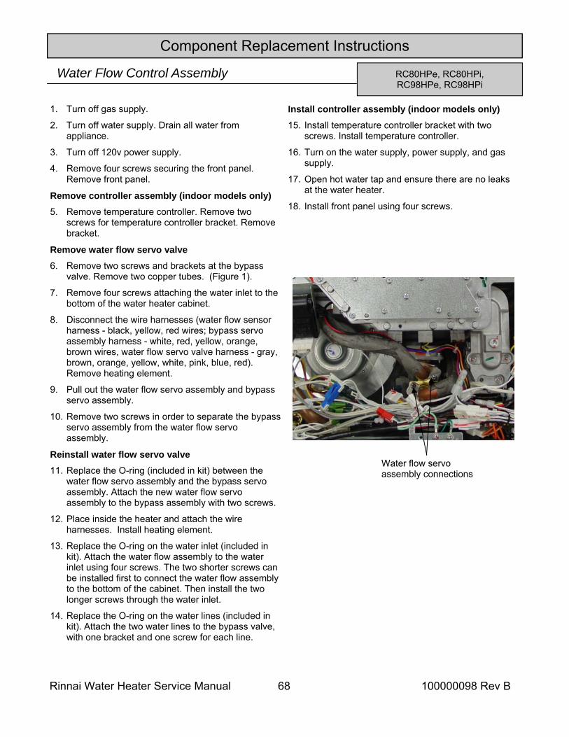
Rinnai Water Heater Service Manual 68 100000098 Rev B
Component Replacement Instructions
RC80HPe, RC80HPi, RC98HPe, RC98HPi
Water Flow Control Assembly
1. Turn off gas supply.
2. Turn off water supply. Drain all water from appliance.
3. Turn off 120v power supply.
4. Remove four screws securing the front panel. Remove front panel.
Remove controller assembly (indoor models only) 5. Remove temperature controller. Remove two
screws for temperature controller bracket. Remove bracket.
Remove water flow servo valve 6. Remove two screws and brackets at the bypass
valve. Remove two copper tubes. (Figure 1).
7. Remove four screws attaching the water inlet to the bottom of the water heater cabinet.
8. Disconnect the wire harnesses (water flow sensor harness - black, yellow, red wires; bypass servo assembly harness - white, red, yellow, orange, brown wires, water flow servo valve harness - gray, brown, orange, yellow, white, pink, blue, red). Remove heating element.
9. Pull out the water flow servo assembly and bypass servo assembly.
10. Remove two screws in order to separate the bypass servo assembly from the water flow servo assembly.
Reinstall water flow servo valve 11. Replace the O-ring (included in kit) between the
water flow servo assembly and the bypass servo assembly. Attach the new water flow servo assembly to the bypass assembly with two screws.
12. Place inside the heater and attach the wire harnesses. Install heating element.
13. Replace the O-ring on the water inlet (included in kit). Attach the water flow assembly to the water inlet using four screws. The two shorter screws can be installed first to connect the water flow assembly to the bottom of the cabinet. Then install the two longer screws through the water inlet.
14. Replace the O-ring on the water lines (included in kit). Attach the two water lines to the bypass valve, with one bracket and one screw for each line.
Install controller assembly (indoor models only) 15. Install temperature controller bracket with two
screws. Install temperature controller.
16. Turn on the water supply, power supply, and gas supply.
17. Open hot water tap and ensure there are no leaks at the water heater.
18. Install front panel using four screws.
Water flow servo assembly connections
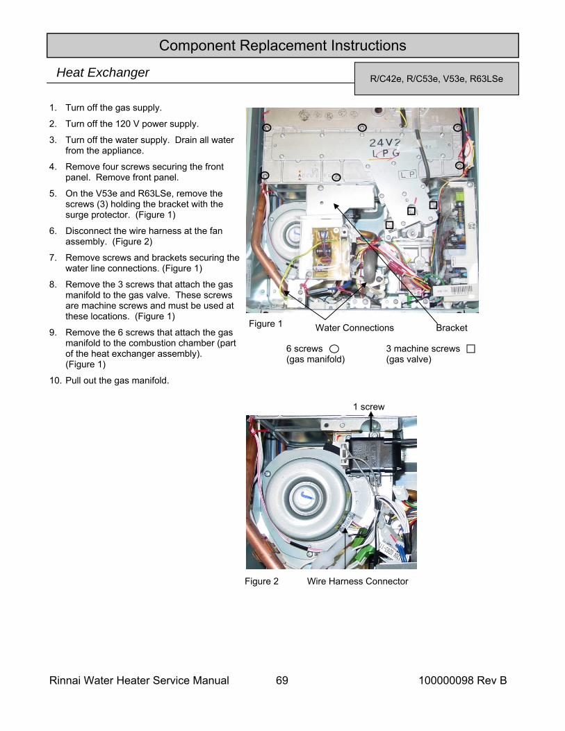
Rinnai Water Heater Service Manual 69 100000098 Rev B
Component Replacement Instructions
R/C42e, R/C53e, V53e, R63LSe Heat Exchanger
1. Turn off the gas supply.
2. Turn off the 120 V power supply.
3. Turn off the water supply. Drain all water from the appliance.
4. Remove four screws securing the front panel. Remove front panel.
5. On the V53e and R63LSe, remove the screws (3) holding the bracket with the surge protector. (Figure 1)
6. Disconnect the wire harness at the fan assembly. (Figure 2)
7. Remove screws and brackets securing the water line connections. (Figure 1)
8. Remove the 3 screws that attach the gas manifold to the gas valve. These screws are machine screws and must be used at these locations. (Figure 1)
9. Remove the 6 screws that attach the gas manifold to the combustion chamber (part of the heat exchanger assembly). (Figure 1)
10. Pull out the gas manifold.
Figure 2
1 screw
Wire Harness Connector
Figure 1
6 screws (gas manifold)
3 machine screws (gas valve)
Water Connections Bracket
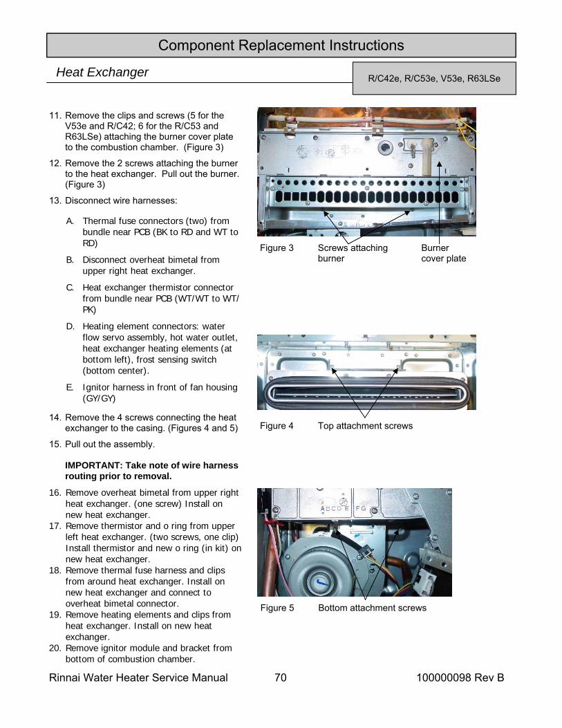
Rinnai Water Heater Service Manual 70 100000098 Rev B
Component Replacement Instructions
R/C42e, R/C53e, V53e, R63LSe Heat Exchanger
11. Remove the clips and screws (5 for the V53e and R/C42; 6 for the R/C53 and R63LSe) attaching the burner cover plate to the combustion chamber. (Figure 3)
12. Remove the 2 screws attaching the burner to the heat exchanger. Pull out the burner. (Figure 3)
13. Disconnect wire harnesses:
14. Remove the 4 screws connecting the heat exchanger to the casing. (Figures 4 and 5)
15. Pull out the assembly. IMPORTANT: Take note of wire harness routing prior to removal.
16. Remove overheat bimetal from upper right heat exchanger. (one screw) Install on new heat exchanger.
17. Remove thermistor and o ring from upper left heat exchanger. (two screws, one clip) Install thermistor and new o ring (in kit) on new heat exchanger.
18. Remove thermal fuse harness and clips from around heat exchanger. Install on new heat exchanger and connect to overheat bimetal connector.
19. Remove heating elements and clips from heat exchanger. Install on new heat exchanger.
20. Remove ignitor module and bracket from bottom of combustion chamber.
Figure 3 Burner cover plate
Screws attaching burner
Figure 4 Top attachment screws
Figure 5 Bottom attachment screws
A. Thermal fuse connectors (two) from bundle near PCB (BK to RD and WT to RD)
B. Disconnect overheat bimetal from upper right heat exchanger.
C. Heat exchanger thermistor connector from bundle near PCB (WT/WT to WT/PK)
D. Heating element connectors: water flow servo assembly, hot water outlet, heat exchanger heating elements (at bottom left), frost sensing switch (bottom center).
E. Ignitor harness in front of fan housing (GY/GY)
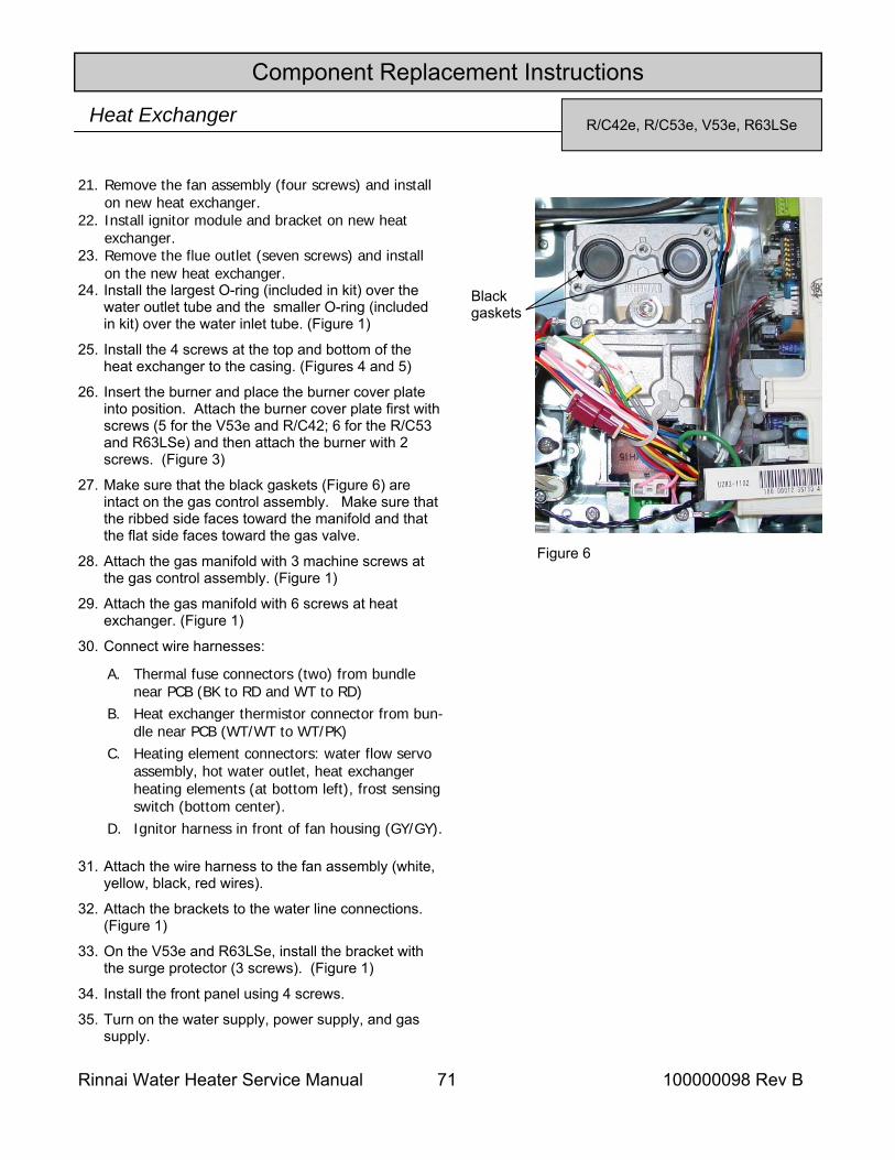
Rinnai Water Heater Service Manual 71 100000098 Rev B
Component Replacement Instructions
R/C42e, R/C53e, V53e, R63LSe Heat Exchanger
21. Remove the fan assembly (four screws) and install on new heat exchanger.
22. Install ignitor module and bracket on new heat exchanger.
23. Remove the flue outlet (seven screws) and install on the new heat exchanger.
24. Install the largest O-ring (included in kit) over the water outlet tube and the smaller O-ring (included in kit) over the water inlet tube. (Figure 1)
25. Install the 4 screws at the top and bottom of the heat exchanger to the casing. (Figures 4 and 5)
26. Insert the burner and place the burner cover plate into position. Attach the burner cover plate first with screws (5 for the V53e and R/C42; 6 for the R/C53 and R63LSe) and then attach the burner with 2 screws. (Figure 3)
27. Make sure that the black gaskets (Figure 6) are intact on the gas control assembly. Make sure that the ribbed side faces toward the manifold and that the flat side faces toward the gas valve.
28. Attach the gas manifold with 3 machine screws at the gas control assembly. (Figure 1)
29. Attach the gas manifold with 6 screws at heat exchanger. (Figure 1)
30. Connect wire harnesses:
31. Attach the wire harness to the fan assembly (white, yellow, black, red wires).
32. Attach the brackets to the water line connections. (Figure 1)
33. On the V53e and R63LSe, install the bracket with the surge protector (3 screws). (Figure 1)
34. Install the front panel using 4 screws.
35. Turn on the water supply, power supply, and gas supply.
Figure 6
Black gaskets
A. Thermal fuse connectors (two) from bundle near PCB (BK to RD and WT to RD)
B. Heat exchanger thermistor connector from bun-dle near PCB (WT/WT to WT/PK)
C. Heating element connectors: water flow servo assembly, hot water outlet, heat exchanger heating elements (at bottom left), frost sensing switch (bottom center).
D. Ignitor harness in front of fan housing (GY/GY).
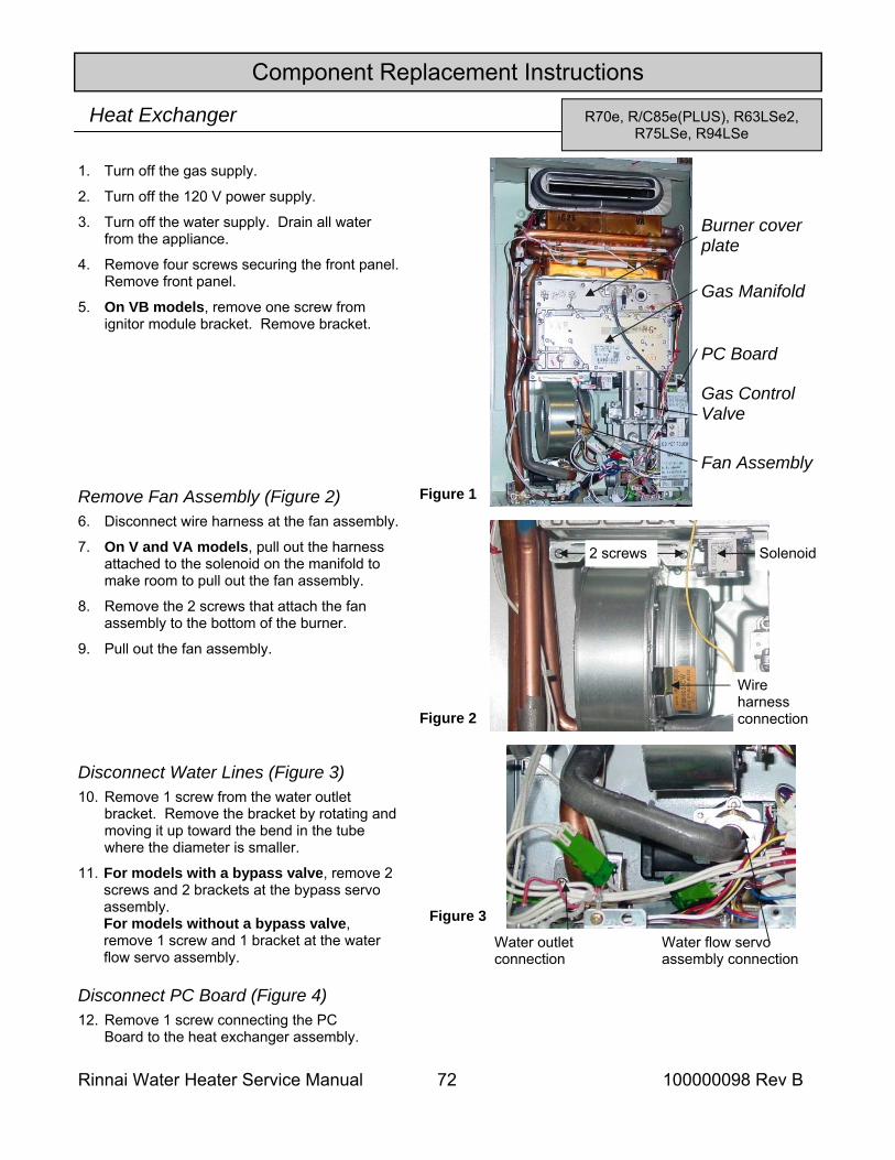
Rinnai Water Heater Service Manual 72 100000098 Rev B
Component Replacement Instructions
R70e, R/C85e(PLUS), R63LSe2, R75LSe, R94LSe
Heat Exchanger
1. Turn off the gas supply.
2. Turn off the 120 V power supply.
3. Turn off the water supply. Drain all water from the appliance.
4. Remove four screws securing the front panel. Remove front panel.
5. On VB models, remove one screw from ignitor module bracket. Remove bracket.
Remove Fan Assembly (Figure 2) 6. Disconnect wire harness at the fan assembly.
7. On V and VA models, pull out the harness attached to the solenoid on the manifold to make room to pull out the fan assembly.
8. Remove the 2 screws that attach the fan assembly to the bottom of the burner.
9. Pull out the fan assembly.
10. Remove 1 screw from the water outlet bracket. Remove the bracket by rotating and moving it up toward the bend in the tube where the diameter is smaller.
11. For models with a bypass valve, remove 2 screws and 2 brackets at the bypass servo assembly. For models without a bypass valve, remove 1 screw and 1 bracket at the water flow servo assembly.
Figure 1
Fan Assembly
Gas Manifold
Burner cover plate
PC Board
Gas Control Valve
Figure 2
Wire harness connection
Solenoid 2 screws
Figure 3
Water outlet connection
Water flow servo assembly connection
Disconnect Water Lines (Figure 3)
Disconnect PC Board (Figure 4) 12. Remove 1 screw connecting the PC
Board to the heat exchanger assembly.
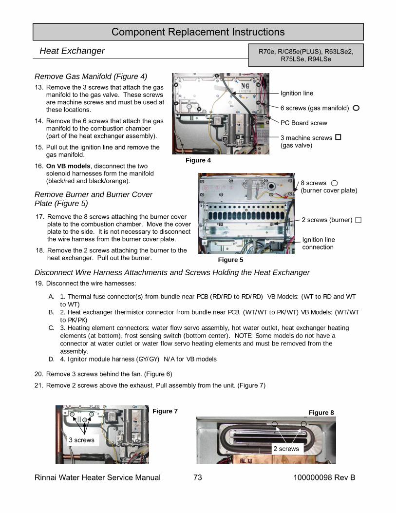
Rinnai Water Heater Service Manual 73 100000098 Rev B
Component Replacement Instructions
R70e, R/C85e(PLUS), R63LSe2, R75LSe, R94LSe
Heat Exchanger
13. Remove the 3 screws that attach the gas manifold to the gas valve. These screws are machine screws and must be used at these locations.
14. Remove the 6 screws that attach the gas manifold to the combustion chamber (part of the heat exchanger assembly).
15. Pull out the ignition line and remove the gas manifold.
16. On VB models, disconnect the two solenoid harnesses form the manifold (black/red and black/orange).
Remove Gas Manifold (Figure 4)
17. Remove the 8 screws attaching the burner cover plate to the combustion chamber. Move the cover plate to the side. It is not necessary to disconnect the wire harness from the burner cover plate.
18. Remove the 2 screws attaching the burner to the heat exchanger. Pull out the burner.
19. Disconnect the wire harnesses:
20. Remove 3 screws behind the fan. (Figure 6)
21. Remove 2 screws above the exhaust. Pull assembly from the unit. (Figure 7)
Disconnect Wire Harness Attachments and Screws Holding the Heat Exchanger
Ignition line 6 screws (gas manifold) PC Board screw 3 machine screws (gas valve)
Figure 4
Ignition line connection
8 screws (burner cover plate)
2 screws (burner)
Figure 5
Remove Burner and Burner Cover Plate (Figure 5)
Figure 8
2 screws
Figure 7
3 screws
A. 1. Thermal fuse connector(s) from bundle near PCB (RD/RD to RD/RD) VB Models: (WT to RD and WT to WT)
B. 2. Heat exchanger thermistor connector from bundle near PCB. (WT/WT to PK/WT) VB Models: (WT/WT to PK/PK)
C. 3. Heating element connectors: water flow servo assembly, hot water outlet, heat exchanger heating elements (at bottom), frost sensing switch (bottom center). NOTE: Some models do not have a connector at water outlet or water flow servo heating elements and must be removed from the assembly.
D. 4. Ignitor module harness (GY/GY) N/A for VB models
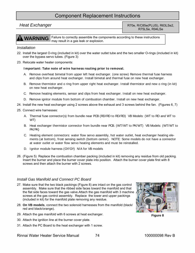
Rinnai Water Heater Service Manual 74 100000098 Rev B
Component Replacement Instructions
R70e, R/C85e(PLUS), R63LSe2, R75LSe, R94LSe
Heat Exchanger
22. Install the largest O-ring (included in kit) over the water outlet tube and the two smaller O-rings (included in kit) over the bypass servo tubes. (Figure 3)
23. Relocate water heater components:
24. Install the new heat exchanger using 2 screws above the exhaust and 3 screws behind the fan. (Figures 6, 7)
25. Connect wire harnesses:
26. (Figure 5) Replace the combustion chamber packing (included in kit) removing any residue from old packing. Insert the burner and place the burner cover plate into position. Attach the burner cover plate first with 8 screws and then attach the burner with 2 screws.
Install Gas Manifold and Connect PC Board 27. Make sure that the two black packings (Figure 8) are intact on the gas control
assembly. Make sure that the ribbed side faces toward the manifold and that the flat side faces toward the gas valve.Attach the gas manifold with 3 machine screws at the gas control assembly. Replace the lower and upper packings (included in kit) for the manifold plate removing any residue.
28. On VB models, connect the two solenoid harnesses from the manifold (black/red and black/orange).
29. Attach the gas manifold with 6 screws at heat exchanger.
30. Attach the ignition line at the burner cover plate.
31. Attach the PC Board to the heat exchanger with 1 screw.
Figure 8
WARNING Failure to correctly assemble the components according to these instructions may result in a gas leak or explosion.
Installation
Important: Take note of wire harness routing prior to removal.
A. Remove overheat bimetal from upper left heat exchanger. (one screw) Remove thermal fuse harness and clips from around heat exchanger. Install bimetal and thermal fuse on new heat exchanger.
B. Remove thermistor and o ring from upper right heat exchanger. Install thermistor and new o ring (in kit) on new heat exchanger.
C. Remove heating elements, sensor and clips from heat exchanger. Install on new heat exchanger.
D. Remove ignitor module from bottom of combustion chamber. Install on new heat exchanger.
A. Thermal fuse connector(s) from bundle near PCB (RD/RD to RD/RD) VB Models: (WT to RD and WT to WT)
B. Heat exchanger thermistor connector from bundle near PCB. (WT/WT to PK/WT) VB Models: (WT/WT to PK/PK)
C. Heating element connectors: water flow servo assembly, hot water outlet, heat exchanger heating ele-ments (at bottom), frost sensing switch (bottom center). NOTE: Some models do not have a connector at water outlet or water flow servo heating elements and must be reinstalled.
D. Ignitor module harness (GY/GY) N/A for VB models
Connect Water Lines (Figure 3) 32. Attach the water outlet line and bracket with 1 screw.
33. Depending on model, attach the line to the water flow servo assembly with 1 screw and 1 bracket or attach the lines to the bypass valve with 1 screws and 1 brackets for each line.
Install Fan Assembly (Figure 2) 34. Install the fan assembly by inserting the tab on the fan assembly into the slot at the base of the heat exchanger and
attaching with two screws.
35. Attach the wire harness to the solenoid on the gas manifold (brown, black wires).
36. Attach the wire harness to the fan assembly (white, yellow, black, red wires).
37. On VB models, install the ignitor module bracket with one screw.
38. Install the front panel using 4 screws. Turn on the water supply, power supply, and gas supply. Check for gas leaks.
Component Replacement Instructions
R70e, R/C85e(PLUS), R63LSe2, R75LSe, R94LSe
Heat Exchanger
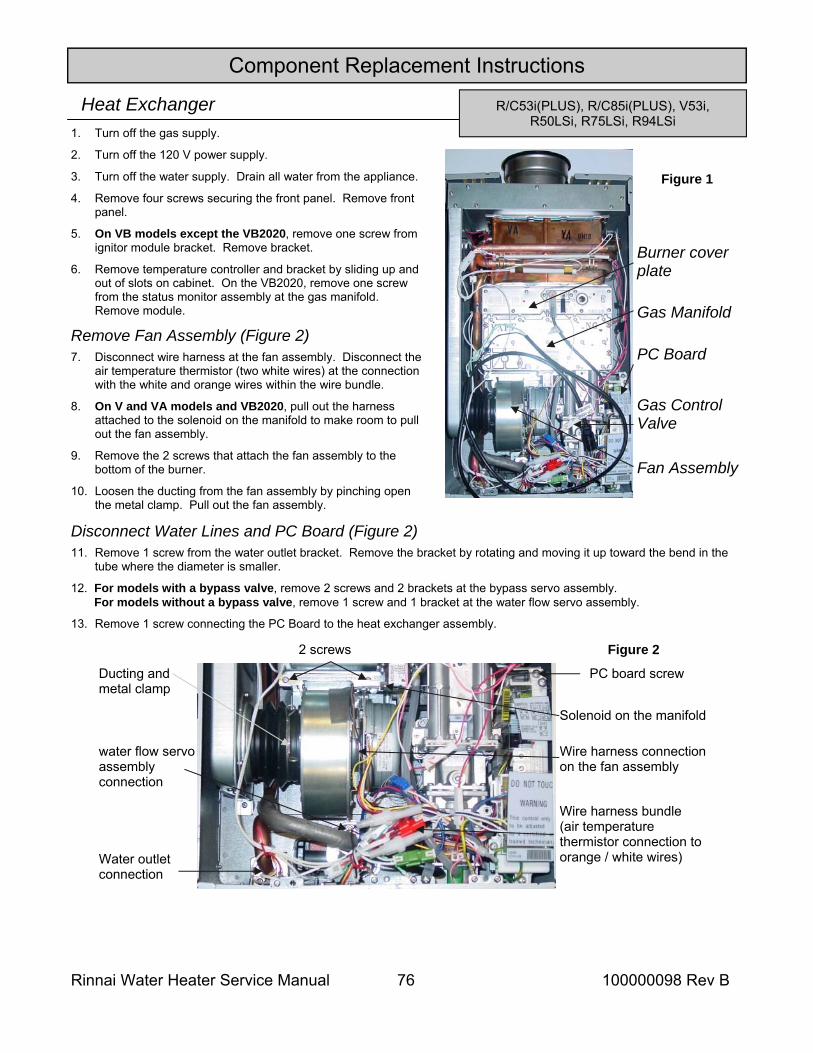
Rinnai Water Heater Service Manual 76 100000098 Rev B
Component Replacement Instructions
Heat Exchanger 1. Turn off the gas supply.
2. Turn off the 120 V power supply.
3. Turn off the water supply. Drain all water from the appliance.
4. Remove four screws securing the front panel. Remove front panel.
5. On VB models except the VB2020, remove one screw from ignitor module bracket. Remove bracket.
6. Remove temperature controller and bracket by sliding up and out of slots on cabinet. On the VB2020, remove one screw from the status monitor assembly at the gas manifold. Remove module.
2 screws
Wire harness connection on the fan assembly
Solenoid on the manifold
Wire harness bundle (air temperature thermistor connection to orange / white wires)
Ducting and metal clamp
Remove Fan Assembly (Figure 2) 7. Disconnect wire harness at the fan assembly. Disconnect the
air temperature thermistor (two white wires) at the connection with the white and orange wires within the wire bundle.
8. On V and VA models and VB2020, pull out the harness attached to the solenoid on the manifold to make room to pull out the fan assembly.
9. Remove the 2 screws that attach the fan assembly to the bottom of the burner.
10. Loosen the ducting from the fan assembly by pinching open the metal clamp. Pull out the fan assembly.
11. Remove 1 screw from the water outlet bracket. Remove the bracket by rotating and moving it up toward the bend in the tube where the diameter is smaller.
12. For models with a bypass valve, remove 2 screws and 2 brackets at the bypass servo assembly. For models without a bypass valve, remove 1 screw and 1 bracket at the water flow servo assembly.
13. Remove 1 screw connecting the PC Board to the heat exchanger assembly.
Disconnect Water Lines and PC Board (Figure 2)
Fan Assembly
Gas Manifold
Burner cover plate
PC Board
Gas Control Valve
Figure 1
Figure 2
Water outlet connection
water flow servo assembly connection
PC board screw
R/C53i(PLUS), R/C85i(PLUS), V53i, R50LSi, R75LSi, R94LSi
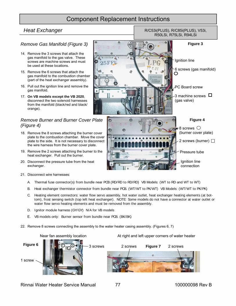
Rinnai Water Heater Service Manual 77 100000098 Rev B
Component Replacement Instructions
Heat Exchanger
14. Remove the 3 screws that attach the gas manifold to the gas valve. These screws are machine screws and must be used at these locations.
15. Remove the 6 screws that attach the gas manifold to the combustion chamber (part of the heat exchanger assembly).
16. Pull out the ignition line and remove the gas manifold.
17. On VB models except the VB 2020, disconnect the two solenoid harnesses from the manifold (black/red and black/orange).
Remove Gas Manifold (Figure 3)
18. Remove the 8 screws attaching the burner cover plate to the combustion chamber. Move the cover plate to the side. It is not necessary to disconnect the wire harness from the burner cover plate.
19. Remove the 2 screws attaching the burner to the heat exchanger. Pull out the burner.
20. Disconnect the pressure tube from the heat exchanger.
Ignition line 6 screws (gas manifold)
PC Board screw 3 machine screws (gas valve)
Figure 3
Pressure tube
Ignition line connection
8 screws (burner cover plate)
2 screws (burner)
Figure 4 Remove Burner and Burner Cover Plate (Figure 4)
21. Disconnect wire harnesses:
22. Remove 8 screws connecting the assembly to the water heater casing assembly. (Figures 6, 7)
At right and left upper corners of water heater Near fan assembly location
2 screws 2 screws Figure 7
1 screw
3 screws Figure 6
R/C53i(PLUS), R/C85i(PLUS), V53i, R50LSi, R75LSi, R94LSi
A. Thermal fuse connector(s) from bundle near PCB (RD/RD to RD/RD) VB Models: (WT to RD and WT to WT)
B. Heat exchanger thermistor connector from bundle near PCB. (WT/WT to PK/WT) VB Models: (WT/WT to PK/PK)
C. Heating element connectors: water flow servo assembly, hot water outlet, heat exchanger heating elements (at bot-tom), frost sensing switch (top left heat exchanger). NOTE: Some models do not have a connector at water outlet or water flow servo heating elements and must be removed from the assembly.
D. Ignitor module harness (GY/GY) N/A for VB models
E. VB models only: Burner sensor from bundle near PCB. (BK/BK)
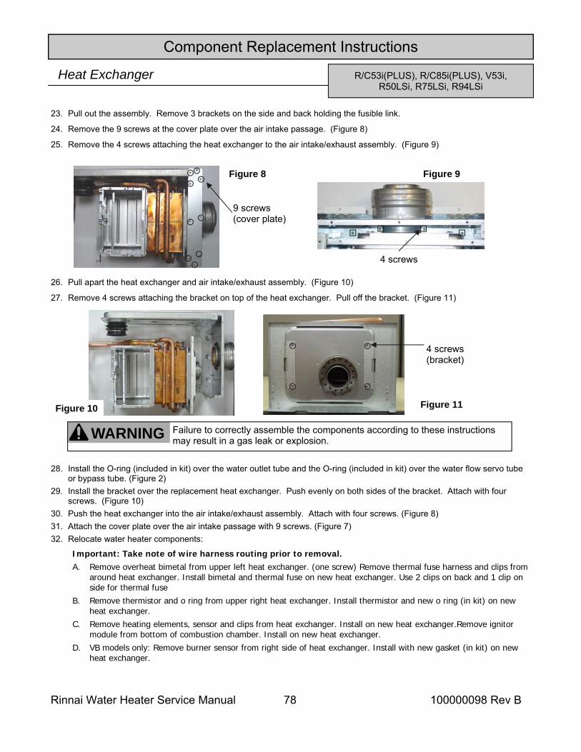
Rinnai Water Heater Service Manual 78 100000098 Rev B
Component Replacement Instructions
Heat Exchanger
23. Pull out the assembly. Remove 3 brackets on the side and back holding the fusible link.
24. Remove the 9 screws at the cover plate over the air intake passage. (Figure 8)
25. Remove the 4 screws attaching the heat exchanger to the air intake/exhaust assembly. (Figure 9)
26. Pull apart the heat exchanger and air intake/exhaust assembly. (Figure 10)
27. Remove 4 screws attaching the bracket on top of the heat exchanger. Pull off the bracket. (Figure 11)
28. Install the O-ring (included in kit) over the water outlet tube and the O-ring (included in kit) over the water flow servo tube or bypass tube. (Figure 2)
29. Install the bracket over the replacement heat exchanger. Push evenly on both sides of the bracket. Attach with four screws. (Figure 10)
30. Push the heat exchanger into the air intake/exhaust assembly. Attach with four screws. (Figure 8) 31. Attach the cover plate over the air intake passage with 9 screws. (Figure 7) 32. Relocate water heater components:
4 screws (bracket)
9 screws (cover plate)
Figure 8
4 screws
Figure 9
Figure 10 Figure 11
WARNING Failure to correctly assemble the components according to these instructions may result in a gas leak or explosion.
R/C53i(PLUS), R/C85i(PLUS), V53i, R50LSi, R75LSi, R94LSi
Important: Take note of wire harness routing prior to removal. A. Remove overheat bimetal from upper left heat exchanger. (one screw) Remove thermal fuse harness and clips from
around heat exchanger. Install bimetal and thermal fuse on new heat exchanger. Use 2 clips on back and 1 clip on side for thermal fuse
B. Remove thermistor and o ring from upper right heat exchanger. Install thermistor and new o ring (in kit) on new heat exchanger.
C. Remove heating elements, sensor and clips from heat exchanger. Install on new heat exchanger.Remove ignitor module from bottom of combustion chamber. Install on new heat exchanger.
D. VB models only: Remove burner sensor from right side of heat exchanger. Install with new gasket (in kit) on new heat exchanger.
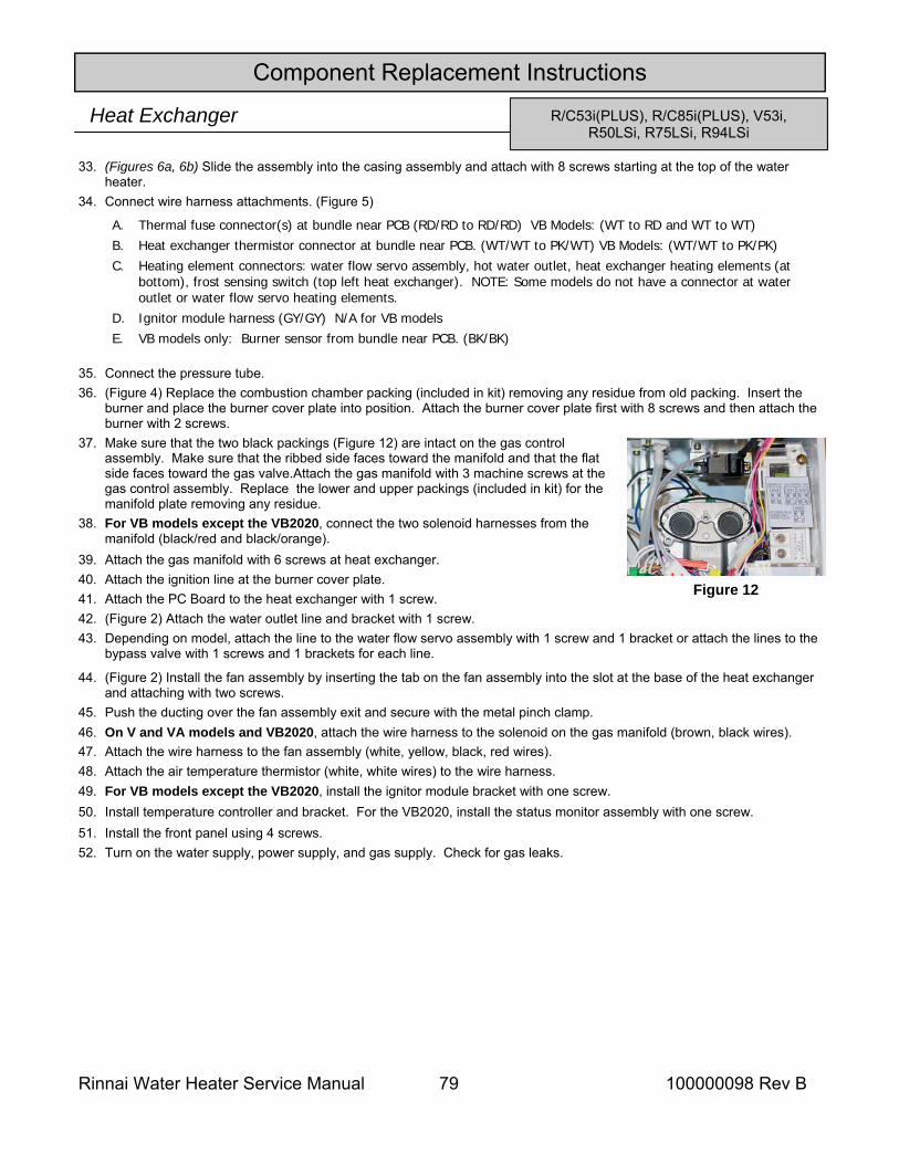
Rinnai Water Heater Service Manual 79 100000098 Rev B
Component Replacement Instructions
Heat Exchanger
33. (Figures 6a, 6b) Slide the assembly into the casing assembly and attach with 8 screws starting at the top of the water heater.
34. Connect wire harness attachments. (Figure 5)
35. Connect the pressure tube. 36. (Figure 4) Replace the combustion chamber packing (included in kit) removing any residue from old packing. Insert the
burner and place the burner cover plate into position. Attach the burner cover plate first with 8 screws and then attach the burner with 2 screws.
37. Make sure that the two black packings (Figure 12) are intact on the gas control assembly. Make sure that the ribbed side faces toward the manifold and that the flat side faces toward the gas valve.Attach the gas manifold with 3 machine screws at the gas control assembly. Replace the lower and upper packings (included in kit) for the manifold plate removing any residue.
38. For VB models except the VB2020, connect the two solenoid harnesses from the manifold (black/red and black/orange).
39. Attach the gas manifold with 6 screws at heat exchanger. 40. Attach the ignition line at the burner cover plate. 41. Attach the PC Board to the heat exchanger with 1 screw. 42. (Figure 2) Attach the water outlet line and bracket with 1 screw. 43. Depending on model, attach the line to the water flow servo assembly with 1 screw and 1 bracket or attach the lines to the
bypass valve with 1 screws and 1 brackets for each line.
44. (Figure 2) Install the fan assembly by inserting the tab on the fan assembly into the slot at the base of the heat exchanger and attaching with two screws.
45. Push the ducting over the fan assembly exit and secure with the metal pinch clamp. 46. On V and VA models and VB2020, attach the wire harness to the solenoid on the gas manifold (brown, black wires). 47. Attach the wire harness to the fan assembly (white, yellow, black, red wires). 48. Attach the air temperature thermistor (white, white wires) to the wire harness. 49. For VB models except the VB2020, install the ignitor module bracket with one screw. 50. Install temperature controller and bracket. For the VB2020, install the status monitor assembly with one screw. 51. Install the front panel using 4 screws. 52. Turn on the water supply, power supply, and gas supply. Check for gas leaks.
Figure 12
R/C53i(PLUS), R/C85i(PLUS), V53i, R50LSi, R75LSi, R94LSi
A. Thermal fuse connector(s) at bundle near PCB (RD/RD to RD/RD) VB Models: (WT to RD and WT to WT) B. Heat exchanger thermistor connector at bundle near PCB. (WT/WT to PK/WT) VB Models: (WT/WT to PK/PK) C. Heating element connectors: water flow servo assembly, hot water outlet, heat exchanger heating elements (at
bottom), frost sensing switch (top left heat exchanger). NOTE: Some models do not have a connector at water outlet or water flow servo heating elements.
D. Ignitor module harness (GY/GY) N/A for VB models E. VB models only: Burner sensor from bundle near PCB. (BK/BK)
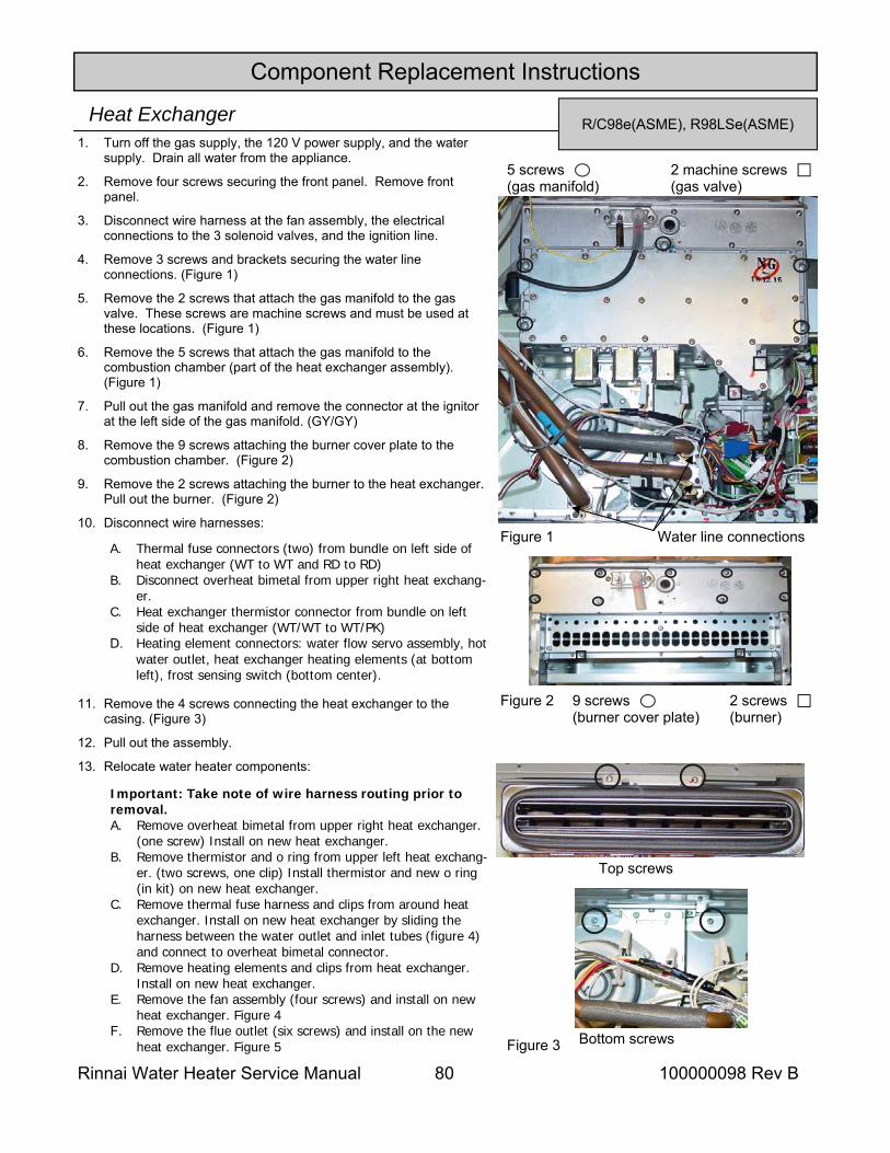
Rinnai Water Heater Service Manual 80 100000098 Rev B
Component Replacement Instructions
R/C98e(ASME), R98LSe(ASME) Heat Exchanger 1. Turn off the gas supply, the 120 V power supply, and the water
supply. Drain all water from the appliance.
2. Remove four screws securing the front panel. Remove front panel.
3. Disconnect wire harness at the fan assembly, the electrical connections to the 3 solenoid valves, and the ignition line.
4. Remove 3 screws and brackets securing the water line connections. (Figure 1)
5. Remove the 2 screws that attach the gas manifold to the gas valve. These screws are machine screws and must be used at these locations. (Figure 1)
6. Remove the 5 screws that attach the gas manifold to the combustion chamber (part of the heat exchanger assembly). (Figure 1)
7. Pull out the gas manifold and remove the connector at the ignitor at the left side of the gas manifold. (GY/GY)
8. Remove the 9 screws attaching the burner cover plate to the combustion chamber. (Figure 2)
9. Remove the 2 screws attaching the burner to the heat exchanger. Pull out the burner. (Figure 2)
10. Disconnect wire harnesses:
11. Remove the 4 screws connecting the heat exchanger to the casing. (Figure 3)
12. Pull out the assembly.
13. Relocate water heater components:
9 screws (burner cover plate)
2 screws (burner)
Figure 2
Water line connections Figure 1
5 screws (gas manifold)
2 machine screws (gas valve)
Figure 3 Bottom screws
Top screws
A. Thermal fuse connectors (two) from bundle on left side of heat exchanger (WT to WT and RD to RD)
B. Disconnect overheat bimetal from upper right heat exchang-er.
C. Heat exchanger thermistor connector from bundle on left side of heat exchanger (WT/WT to WT/PK)
D. Heating element connectors: water flow servo assembly, hot water outlet, heat exchanger heating elements (at bottom left), frost sensing switch (bottom center).
Important: Take note of wire harness routing prior to removal. A. Remove overheat bimetal from upper right heat exchanger.
(one screw) Install on new heat exchanger. B. Remove thermistor and o ring from upper left heat exchang-
er. (two screws, one clip) Install thermistor and new o ring (in kit) on new heat exchanger.
C. Remove thermal fuse harness and clips from around heat exchanger. Install on new heat exchanger by sliding the harness between the water outlet and inlet tubes (figure 4) and connect to overheat bimetal connector.
D. Remove heating elements and clips from heat exchanger. Install on new heat exchanger.
E. Remove the fan assembly (four screws) and install on new heat exchanger. Figure 4
F. Remove the flue outlet (six screws) and install on the new heat exchanger. Figure 5
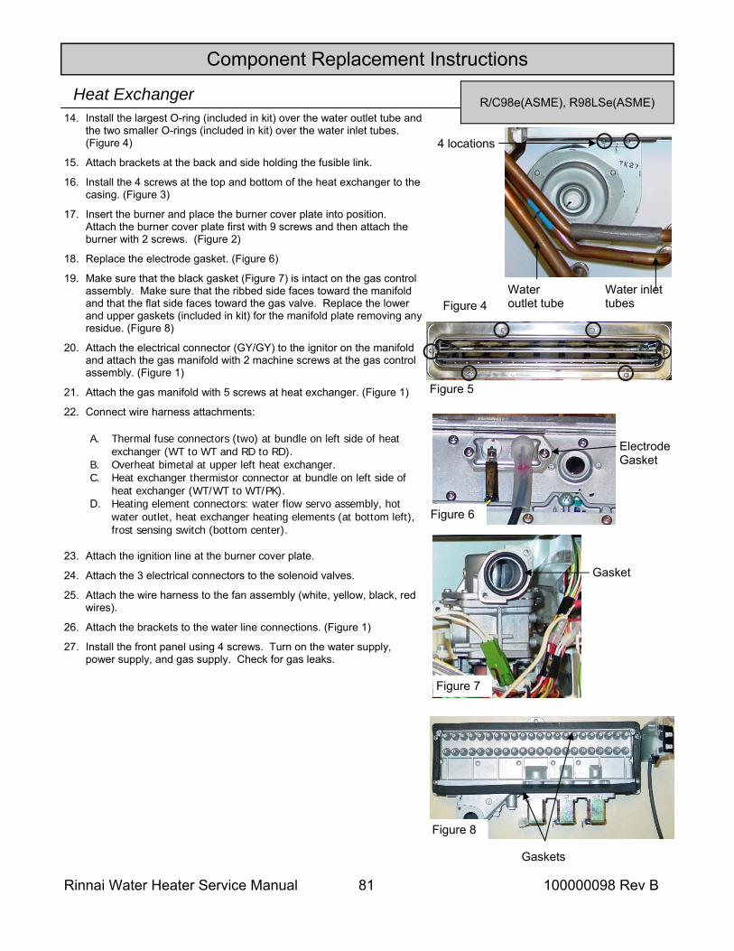
Rinnai Water Heater Service Manual 81 100000098 Rev B
Component Replacement Instructions
R/C98e(ASME), R98LSe(ASME) Heat Exchanger 14. Install the largest O-ring (included in kit) over the water outlet tube and
the two smaller O-rings (included in kit) over the water inlet tubes. (Figure 4)
15. Attach brackets at the back and side holding the fusible link.
16. Install the 4 screws at the top and bottom of the heat exchanger to the casing. (Figure 3)
17. Insert the burner and place the burner cover plate into position. Attach the burner cover plate first with 9 screws and then attach the burner with 2 screws. (Figure 2)
18. Replace the electrode gasket. (Figure 6)
19. Make sure that the black gasket (Figure 7) is intact on the gas control assembly. Make sure that the ribbed side faces toward the manifold and that the flat side faces toward the gas valve. Replace the lower and upper gaskets (included in kit) for the manifold plate removing any residue. (Figure 8)
20. Attach the electrical connector (GY/GY) to the ignitor on the manifold and attach the gas manifold with 2 machine screws at the gas control assembly. (Figure 1)
21. Attach the gas manifold with 5 screws at heat exchanger. (Figure 1)
22. Connect wire harness attachments:
23. Attach the ignition line at the burner cover plate.
24. Attach the 3 electrical connectors to the solenoid valves.
25. Attach the wire harness to the fan assembly (white, yellow, black, red wires).
26. Attach the brackets to the water line connections. (Figure 1)
27. Install the front panel using 4 screws. Turn on the water supply, power supply, and gas supply. Check for gas leaks.
Figure 7
Gasket
Figure 8
Gaskets
Figure 6
Electrode Gasket
Figure 4
4 locations
Water outlet tube
Water inlet tubes
Figure 5
A. Thermal fuse connectors (two) at bundle on left side of heat exchanger (WT to WT and RD to RD).
B. Overheat bimetal at upper left heat exchanger. C. Heat exchanger thermistor connector at bundle on left side of
heat exchanger (WT/WT to WT/PK). D. Heating element connectors: water flow servo assembly, hot
water outlet, heat exchanger heating elements (at bottom left), frost sensing switch (bottom center).
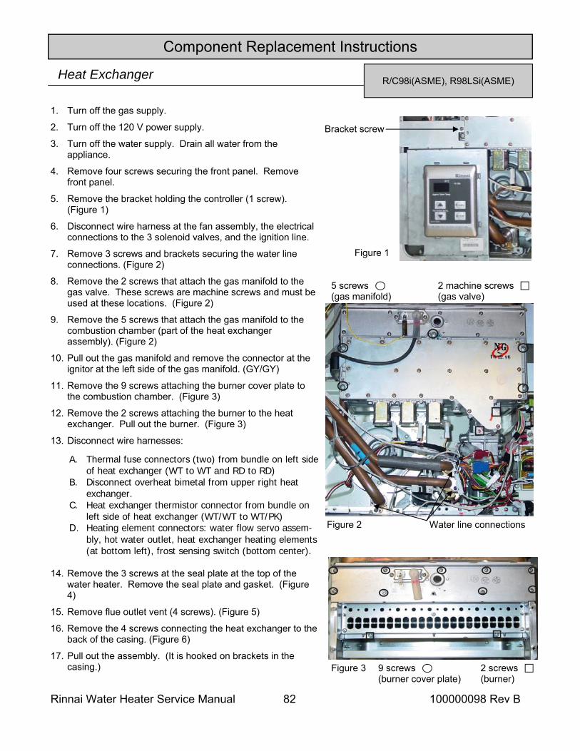
Rinnai Water Heater Service Manual 82 100000098 Rev B
Component Replacement Instructions
R/C98i(ASME), R98LSi(ASME) Heat Exchanger
1. Turn off the gas supply.
2. Turn off the 120 V power supply.
3. Turn off the water supply. Drain all water from the appliance.
4. Remove four screws securing the front panel. Remove front panel.
5. Remove the bracket holding the controller (1 screw). (Figure 1)
6. Disconnect wire harness at the fan assembly, the electrical connections to the 3 solenoid valves, and the ignition line.
7. Remove 3 screws and brackets securing the water line connections. (Figure 2)
8. Remove the 2 screws that attach the gas manifold to the gas valve. These screws are machine screws and must be used at these locations. (Figure 2)
9. Remove the 5 screws that attach the gas manifold to the combustion chamber (part of the heat exchanger assembly). (Figure 2)
10. Pull out the gas manifold and remove the connector at the ignitor at the left side of the gas manifold. (GY/GY)
11. Remove the 9 screws attaching the burner cover plate to the combustion chamber. (Figure 3)
12. Remove the 2 screws attaching the burner to the heat exchanger. Pull out the burner. (Figure 3)
13. Disconnect wire harnesses:
14. Remove the 3 screws at the seal plate at the top of the water heater. Remove the seal plate and gasket. (Figure 4)
15. Remove flue outlet vent (4 screws). (Figure 5)
16. Remove the 4 screws connecting the heat exchanger to the back of the casing. (Figure 6)
17. Pull out the assembly. (It is hooked on brackets in the casing.)
Bracket screw
Figure 1
9 screws (burner cover plate)
2 screws (burner)
Figure 3
Water line connections Figure 2
5 screws (gas manifold)
2 machine screws (gas valve)
A. Thermal fuse connectors (two) from bundle on left side of heat exchanger (WT to WT and RD to RD)
B. Disconnect overheat bimetal from upper right heat exchanger.
C. Heat exchanger thermistor connector from bundle on left side of heat exchanger (WT/WT to WT/PK)
D. Heating element connectors: water flow servo assem-bly, hot water outlet, heat exchanger heating elements (at bottom left), frost sensing switch (bottom center).
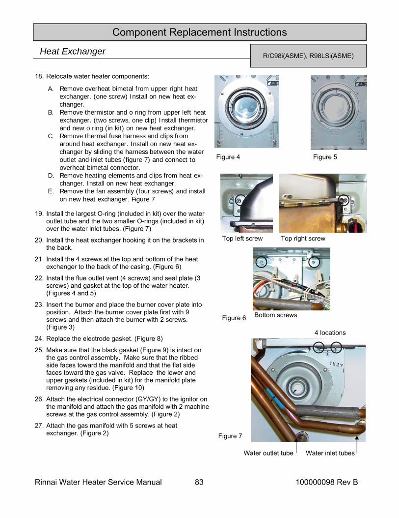
Rinnai Water Heater Service Manual 83 100000098 Rev B
Component Replacement Instructions
R/C98i(ASME), R98LSi(ASME) Heat Exchanger
18. Relocate water heater components:
19. Install the largest O-ring (included in kit) over the water outlet tube and the two smaller O-rings (included in kit) over the water inlet tubes. (Figure 7)
20. Install the heat exchanger hooking it on the brackets in the back.
21. Install the 4 screws at the top and bottom of the heat exchanger to the back of the casing. (Figure 6)
22. Install the flue outlet vent (4 screws) and seal plate (3 screws) and gasket at the top of the water heater. (Figures 4 and 5)
23. Insert the burner and place the burner cover plate into position. Attach the burner cover plate first with 9 screws and then attach the burner with 2 screws. (Figure 3)
24. Replace the electrode gasket. (Figure 8)
25. Make sure that the black gasket (Figure 9) is intact on the gas control assembly. Make sure that the ribbed side faces toward the manifold and that the flat side faces toward the gas valve. Replace the lower and upper gaskets (included in kit) for the manifold plate removing any residue. (Figure 10)
26. Attach the electrical connector (GY/GY) to the ignitor on the manifold and attach the gas manifold with 2 machine screws at the gas control assembly. (Figure 2)
27. Attach the gas manifold with 5 screws at heat exchanger. (Figure 2)
Figure 4 Figure 5
Figure 7
Figure 6
Top left screw Top right screw
Bottom screws
4 locations
Water outlet tube Water inlet tubes
A. Remove overheat bimetal from upper right heat exchanger. (one screw) Install on new heat ex-changer.
B. Remove thermistor and o ring from upper left heat exchanger. (two screws, one clip) Install thermistor and new o ring (in kit) on new heat exchanger.
C. Remove thermal fuse harness and clips from around heat exchanger. Install on new heat ex-changer by sliding the harness between the water outlet and inlet tubes (figure 7) and connect to overheat bimetal connector.
D. Remove heating elements and clips from heat ex-changer. Install on new heat exchanger.
E. Remove the fan assembly (four screws) and install on new heat exchanger. Figure 7
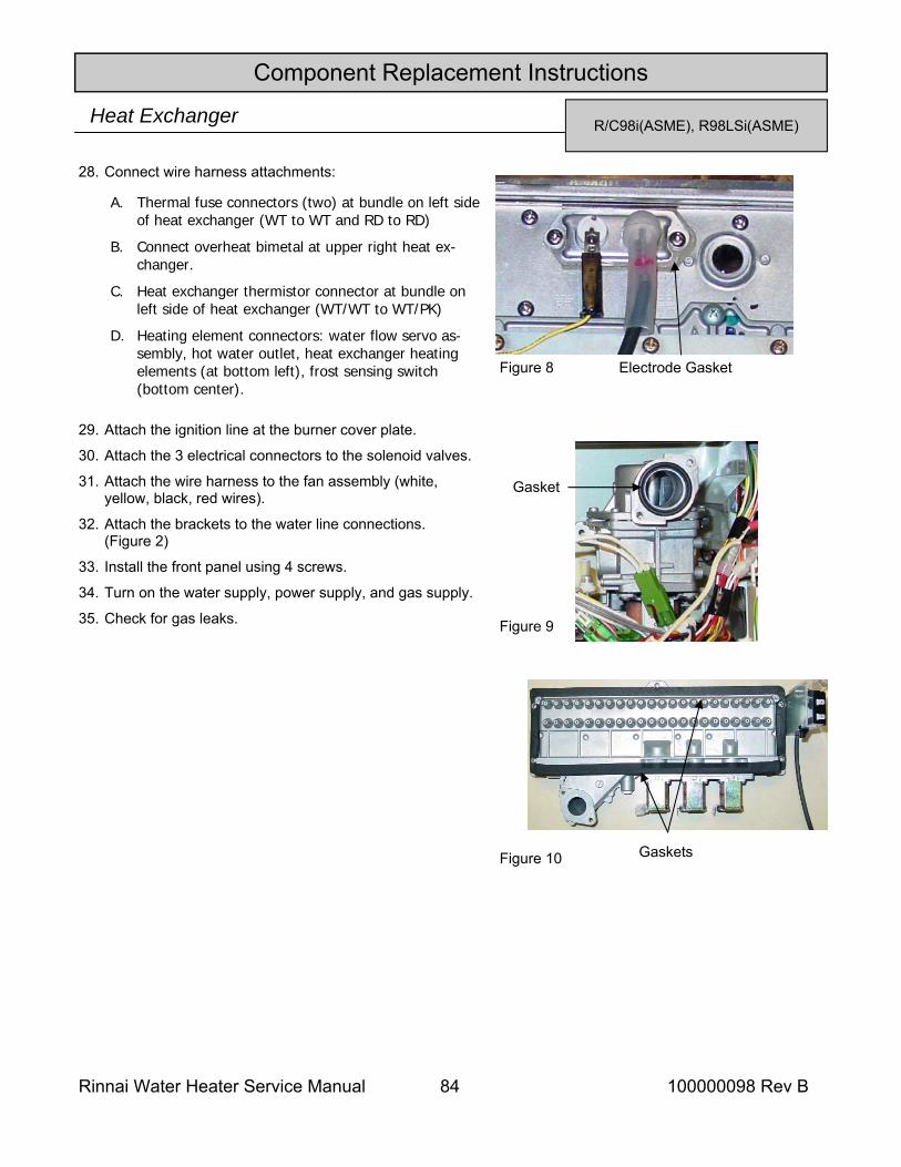
Rinnai Water Heater Service Manual 84 100000098 Rev B
Component Replacement Instructions
R/C98i(ASME), R98LSi(ASME) Heat Exchanger
28. Connect wire harness attachments:
29. Attach the ignition line at the burner cover plate.
30. Attach the 3 electrical connectors to the solenoid valves.
31. Attach the wire harness to the fan assembly (white, yellow, black, red wires).
32. Attach the brackets to the water line connections. (Figure 2)
33. Install the front panel using 4 screws.
34. Turn on the water supply, power supply, and gas supply.
35. Check for gas leaks. Figure 9
Gasket
Figure 10 Gaskets
Figure 8 Electrode Gasket
A. Thermal fuse connectors (two) at bundle on left side of heat exchanger (WT to WT and RD to RD)
B. Connect overheat bimetal at upper right heat ex-changer.
C. Heat exchanger thermistor connector at bundle on left side of heat exchanger (WT/WT to WT/PK)
D. Heating element connectors: water flow servo as-sembly, hot water outlet, heat exchanger heating elements (at bottom left), frost sensing switch (bottom center).
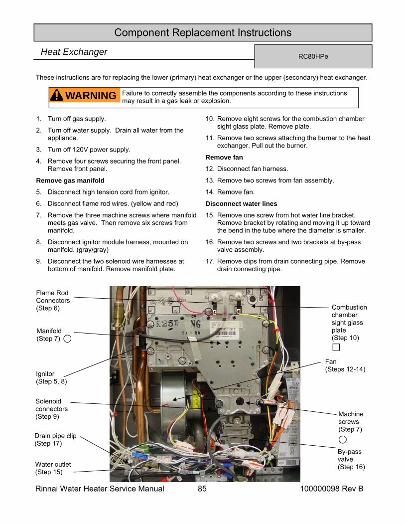
Rinnai Water Heater Service Manual 85 100000098 Rev B
Component Replacement Instructions
RC80HPe Heat Exchanger
1. Turn off gas supply.
2. Turn off water supply. Drain all water from the appliance.
3. Turn off 120V power supply.
4. Remove four screws securing the front panel. Remove front panel.
Remove gas manifold 5. Disconnect high tension cord from ignitor.
6. Disconnect flame rod wires. (yellow and red)
7. Remove the three machine screws where manifold meets gas valve. Then remove six screws from manifold.
8. Disconnect ignitor module harness, mounted on manifold. (gray/gray)
9. Disconnect the two solenoid wire harnesses at bottom of manifold. Remove manifold plate.
10. Remove eight screws for the combustion chamber sight glass plate. Remove plate.
11. Remove two screws attaching the burner to the heat exchanger. Pull out the burner.
Remove fan
12. Disconnect fan harness.
13. Remove two screws from fan assembly.
14. Remove fan.
Disconnect water lines 15. Remove one screw from hot water line bracket.
Remove bracket by rotating and moving it up toward the bend in the tube where the diameter is smaller.
16. Remove two screws and two brackets at by-pass valve assembly.
17. Remove clips from drain connecting pipe. Remove drain connecting pipe.
WARNING Failure to correctly assemble the components according to these instructions may result in a gas leak or explosion.
Manifold (Step 7)
By-pass valve (Step 16) Water outlet
(Step 15)
Ignitor (Step 5, 8)
Flame Rod Connectors (Step 6)
Solenoid connectors (Step 9) Machine
screws (Step 7)
Combustion chamber sight glass plate (Step 10)
Drain pipe clip (Step 17)
Fan (Steps 12-14)
These instructions are for replacing the lower (primary) heat exchanger or the upper (secondary) heat exchanger.
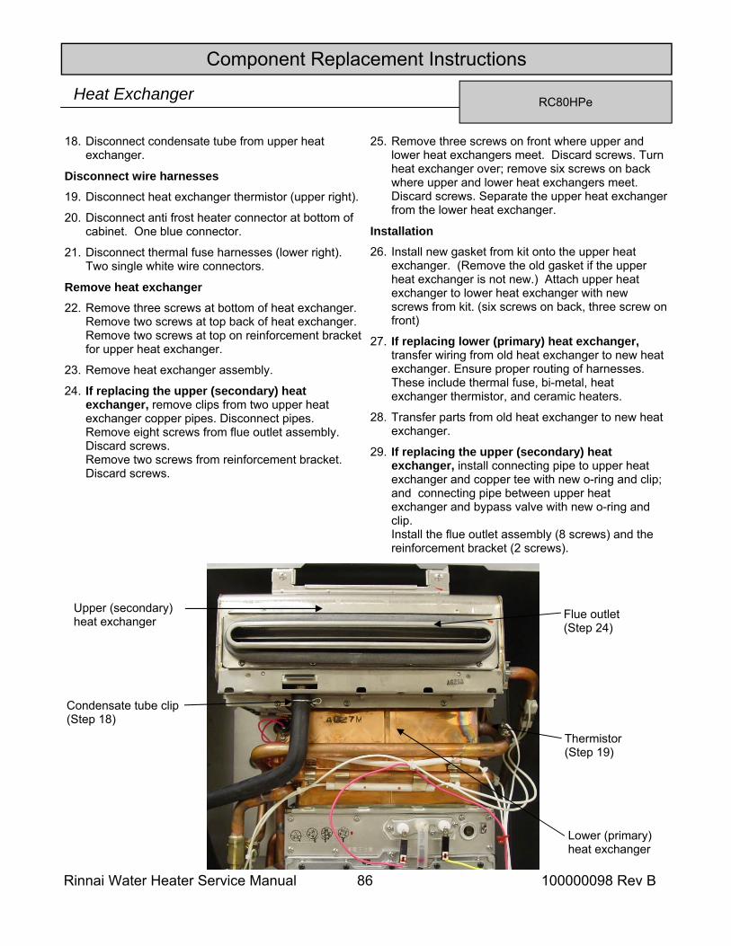
Rinnai Water Heater Service Manual 86 100000098 Rev B
Component Replacement Instructions
RC80HPe Heat Exchanger
18. Disconnect condensate tube from upper heat exchanger.
Disconnect wire harnesses 19. Disconnect heat exchanger thermistor (upper right).
20. Disconnect anti frost heater connector at bottom of cabinet. One blue connector.
21. Disconnect thermal fuse harnesses (lower right). Two single white wire connectors.
Remove heat exchanger 22. Remove three screws at bottom of heat exchanger.
Remove two screws at top back of heat exchanger. Remove two screws at top on reinforcement bracket for upper heat exchanger.
23. Remove heat exchanger assembly.
24. If replacing the upper (secondary) heat exchanger, remove clips from two upper heat exchanger copper pipes. Disconnect pipes. Remove eight screws from flue outlet assembly. Discard screws. Remove two screws from reinforcement bracket. Discard screws.
25. Remove three screws on front where upper and lower heat exchangers meet. Discard screws. Turn heat exchanger over; remove six screws on back where upper and lower heat exchangers meet. Discard screws. Separate the upper heat exchanger from the lower heat exchanger.
Installation 26. Install new gasket from kit onto the upper heat
exchanger. (Remove the old gasket if the upper heat exchanger is not new.) Attach upper heat exchanger to lower heat exchanger with new screws from kit. (six screws on back, three screw on front)
27. If replacing lower (primary) heat exchanger, transfer wiring from old heat exchanger to new heat exchanger. Ensure proper routing of harnesses. These include thermal fuse, bi-metal, heat exchanger thermistor, and ceramic heaters.
28. Transfer parts from old heat exchanger to new heat exchanger.
29. If replacing the upper (secondary) heat exchanger, install connecting pipe to upper heat exchanger and copper tee with new o-ring and clip; and connecting pipe between upper heat exchanger and bypass valve with new o-ring and clip. Install the flue outlet assembly (8 screws) and the reinforcement bracket (2 screws).
Upper (secondary) heat exchanger
Lower (primary) heat exchanger
Thermistor (Step 19)
Flue outlet(Step 24)
Condensate tube clip (Step 18)
Rinnai Water Heater Service Manual 87 100000098 Rev B
Component Replacement Instructions
RC80HPe Heat Exchanger
30. Install heat exchanger assembly in case. Place bottom in cabinet first. Attach with five screws. (two at top back and three on bottom). Attach reinforcement bracket with two screws.
Install water and drain lines 31. Install drain connecting pipe with new o-rings and
attach with new clips.
32. Attach connecting pipe to by-pass valve with one screw and bracket. Attach other water line with one screw and bracket.
33. Attach the hot water outlet line to the hot water outlet fitting with one screw and bracket. Reconnect condensate tube to upper heat exchanger.
Reconnect wire harness 34. Reconnect heat exchanger thermistor (upper right).
35. Reconnect anti frost connector at bottom of cabinet. One blue connector.
36. Reconnect thermal fuse harnesses (lower right). Two single white wire connectors.
Install burner and burner cover plate 37. Install burner assembly with two screws. Remove
combustion chamber packing on sight glass plate. Install new packing, in kit, on sight glass plate. Install combustion chamber sight glass plate with eight screws.
Install fan 38. Reinstall fan with two screws. Install fan connector.
Install gas manifold 39. Remove packing from gas control assembly.
Discard. Install new packing, in kit, on gas control assembly.
40. Remove the packing for manifold. Install new packing, in kit, on gas manifold.
41. Reconnect the two solenoid wire harnesses at bottom of manifold.
42. Reconnect ignitor module harness, mounted on manifold. (gray/gray)
43. Attach the gas manifold with three machine screws at the gas control assembly. Install six screws on gas manifold to heat exchanger. Attach wire harness ties.
Reconnect flame rod connectors and igniter 44. Install two flame rod connectors. (marked )
45. Attach ignitor high tension cord to the electrode.
46. Turn on water supply, power supply, and gas supply. Check for gas and water leaks. Perform operational checks.
47. Install the front panel using four screws.
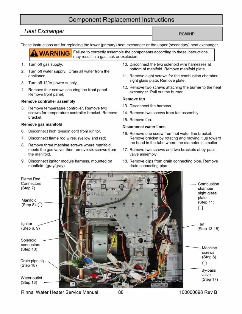
Rinnai Water Heater Service Manual 88 100000098 Rev B
Component Replacement Instructions
RC80HPi Heat Exchanger
1. Turn off gas supply.
2. Turn off water supply. Drain all water from the appliance.
3. Turn off 120V power supply.
4. Remove four screws securing the front panel. Remove front panel.
Remove controller assembly 5. Remove temperature controller. Remove two
screws for temperature controller bracket. Remove bracket.
Remove gas manifold 6. Disconnect high tension cord from ignitor.
7. Disconnect flame rod wires. (yellow and red)
8. Remove three machine screws where manifold meets the gas valve, then remove six screws from the manifold.
9. Disconnect ignitor module harness, mounted on manifold. (gray/gray)
10. Disconnect the two solenoid wire harnesses at bottom of manifold. Remove manifold plate.
11. Remove eight screws for the combustion chamber sight glass plate. Remove plate.
12. Remove two screws attaching the burner to the heat exchanger. Pull out the burner.
Remove fan 13. Disconnect fan harness.
14. Remove two screws from fan assembly.
15. Remove fan.
Disconnect water lines 16. Remove one screw from hot water line bracket.
Remove bracket by rotating and moving it up toward the bend in the tube where the diameter is smaller.
17. Remove two screws and two brackets at by-pass valve assembly.
18. Remove clips from drain connecting pipe. Remove drain connecting pipe.
WARNING Failure to correctly assemble the components according to these instructions may result in a gas leak or explosion.
Manifold (Step 8)
By-pass valve (Step 17) Water outlet
(Step 16)
Ignitor (Step 6, 9)
Flame Rod Connectors (Step 7)
Solenoid connectors (Step 10) Machine
screws (Step 8)
Combustion chamber sight glass plate (Step 11)
Drain pipe clip (Step 18)
Fan (Step 13-15)
These instructions are for replacing the lower (primary) heat exchanger or the upper (secondary) heat exchanger.
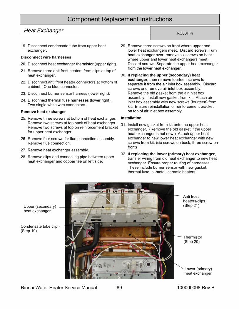
Rinnai Water Heater Service Manual 89 100000098 Rev B
Component Replacement Instructions
RC80HPi Heat Exchanger
19. Disconnect condensate tube from upper heat exchanger.
Disconnect wire harnesses 20. Disconnect heat exchanger thermistor (upper right).
21. Remove three anti frost heaters from clips at top of heat exchanger.
22. Disconnect anti frost heater connectors at bottom of cabinet. One blue connector.
23. Disconnect burner sensor harness (lower right).
24. Disconnect thermal fuse harnesses (lower right). Two single white wire connectors.
Remove heat exchanger 25. Remove three screws at bottom of heat exchanger.
Remove two screws at top back of heat exchanger. Remove two screws at top on reinforcement bracket for upper heat exchanger.
26. Remove four screws for flue connection assembly. Remove flue connection.
27. Remove heat exchanger assembly.
28. Remove clips and connecting pipe between upper heat exchanger and copper tee on left side.
29. Remove three screws on front where upper and lower heat exchangers meet. Discard screws. Turn heat exchanger over; remove six screws on back where upper and lower heat exchangers meet. Discard screws. Separate the upper heat exchanger from the lower heat exchanger.
30. If replacing the upper (secondary) heat exchanger, then remove fourteen screws to separate it from the air inlet box assembly. Discard screws and remove air inlet box assembly. Remove the old gasket from the air inlet box assembly. Install new gasket from kit. Attach air inlet box assembly with new screws (fourteen) from kit. Ensure reinstallation of reinforcement bracket on top of air inlet box assembly.
Installation
31. Install new gasket from kit onto the upper heat exchanger. (Remove the old gasket if the upper heat exchanger is not new.) Attach upper heat exchanger to new lower heat exchanger with new screws from kit. (six screws on back, three screw on front)
32. If replacing the lower (primary) heat exchanger, transfer wiring from old heat exchanger to new heat exchanger. Ensure proper routing of harnesses. These include burner sensor with new gasket, thermal fuse, bi-metal, ceramic heaters.
Upper (secondary) heat exchanger
Lower (primary) heat exchanger
Thermistor (Step 20)
Anti frost heaters/clips(Step 21)
Condensate tube clip (Step 19)
Rinnai Water Heater Service Manual 90 100000098 Rev B
Component Replacement Instructions
RC80HPi Heat Exchanger
33. If replacing the lower (primary) heat exchanger, transfer parts from old heat exchanger to new heat exchanger. These include connecting pipe between upper heat exchanger and copper tee with new o-rings and clips, connecting pipe between upper heat exchanger and bypass valve with new o-ring and clip.
34. Install heat exchanger assembly in case. Place bottom in cabinet first. Attach with five screws. (two at top back and three on bottom) Attach reinforcement bracket with two screws.
35. Remove old gasket from flue connection assembly. Install new gasket from kit. Attach flue connections assembly with four screws.
Install water and drain lines 36. Install drain connecting pipe with new o-rings and
attach with new clips.
37. Attach water inlet connecting pipe with new o-rings at by-pass valve with one screw and bracket. Attach other water line with one screw and bracket.
38. Attach the hot water outlet line to the hot water outlet fitting with one screw and bracket. Reconnect condensate tube at upper heat exchanger.
Reconnect wire harness 39. Reconnect heat exchanger thermistor (upper right).
40. Install three anti frost heaters in clips at top of upper heat exchanger.
41. Reconnect anti frost connectors at bottom of cabinet. One blue connector.
42. Reconnect burner sensor harness (lower right).
43. Reconnect thermal fuse harnesses (lower right). Two single white wire connectors.
Install burner and burner cover plate 44. Install burner assembly with two screws. Remove
combustion chamber packing on sight glass plate. Install new packing, in kit, on sight glass plate. Install combustion chamber sight glass plate with eight screws.
Install fan 45. Reinstall fan with two screws. Install fan connector.
Install gas manifold 46. Remove packing from gas control assembly.
Discard. Install new packing, in kit, on gas control assembly.
47. Remove the packing for manifold. Install new packing, in kit, on gas manifold.
48. Reconnect ignitor module harness, mounted on manifold. (gray/gray)
49. Install two connectors to the solenoids on the gas manifold. (marked)
50. Attach the gas manifold with three machine screws at the gas control assembly. Install six screws on gas manifold to heat exchanger. Attach wire harness ties.
Reconnect flame rod connectors and igniter 51. Install two flame rod connectors. (marked )
52. Attach ignitor high tension cord to the electrode.
53. Attach controller bracket with one machine screw and one screw from power wire clamp. Install controller in bracket.
54. Turn on water supply, power supply, and gas supply. Check for gas and water leaks. Perform operational checks.
55. Install the front panel using four screws.
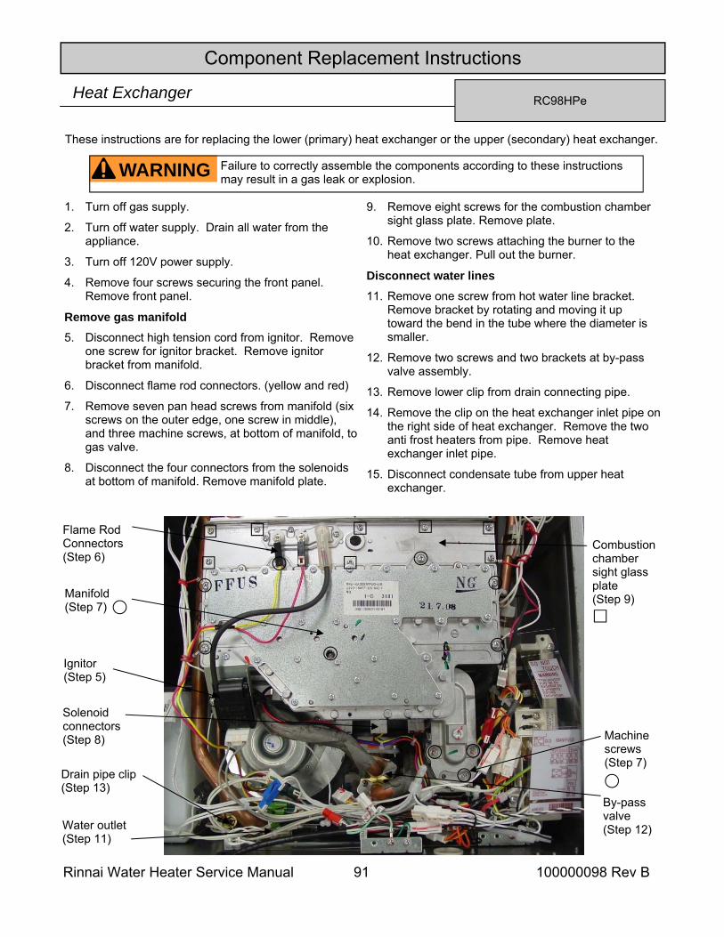
Rinnai Water Heater Service Manual 91 100000098 Rev B
Component Replacement Instructions
RC98HPe Heat Exchanger
1. Turn off gas supply.
2. Turn off water supply. Drain all water from the appliance.
3. Turn off 120V power supply.
4. Remove four screws securing the front panel. Remove front panel.
Remove gas manifold 5. Disconnect high tension cord from ignitor. Remove
one screw for ignitor bracket. Remove ignitor bracket from manifold.
6. Disconnect flame rod connectors. (yellow and red)
7. Remove seven pan head screws from manifold (six screws on the outer edge, one screw in middle), and three machine screws, at bottom of manifold, to gas valve.
8. Disconnect the four connectors from the solenoids at bottom of manifold. Remove manifold plate.
9. Remove eight screws for the combustion chamber sight glass plate. Remove plate.
10. Remove two screws attaching the burner to the heat exchanger. Pull out the burner.
Disconnect water lines 11. Remove one screw from hot water line bracket.
Remove bracket by rotating and moving it up toward the bend in the tube where the diameter is smaller.
12. Remove two screws and two brackets at by-pass valve assembly.
13. Remove lower clip from drain connecting pipe.
14. Remove the clip on the heat exchanger inlet pipe on the right side of heat exchanger. Remove the two anti frost heaters from pipe. Remove heat exchanger inlet pipe.
15. Disconnect condensate tube from upper heat exchanger.
WARNING Failure to correctly assemble the components according to these instructions may result in a gas leak or explosion.
Manifold (Step 7)
By-pass valve (Step 12) Water outlet
(Step 11)
Ignitor (Step 5)
Flame Rod Connectors (Step 6)
Solenoid connectors (Step 8) Machine
screws (Step 7)
Combustion chamber sight glass plate (Step 9)
Drain pipe clip (Step 13)
These instructions are for replacing the lower (primary) heat exchanger or the upper (secondary) heat exchanger.
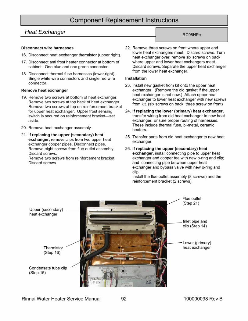
Rinnai Water Heater Service Manual 92 100000098 Rev B
Component Replacement Instructions
RC98HPe Heat Exchanger
Disconnect wire harnesses 16. Disconnect heat exchanger thermistor (upper right).
17. Disconnect anti frost heater connector at bottom of cabinet. One blue and one green connector.
18. Disconnect thermal fuse harnesses (lower right). Single white wire connectors and single red wire connector.
Remove heat exchanger 19. Remove two screws at bottom of heat exchanger.
Remove two screws at top back of heat exchanger. Remove two screws at top on reinforcement bracket for upper heat exchanger. Upper frost sensing switch is secured on reinforcement bracket—set aside.
20. Remove heat exchanger assembly.
21. If replacing the upper (secondary) heat exchanger, remove clips from two upper heat exchanger copper pipes. Disconnect pipes. Remove eight screws from flue outlet assembly. Discard screws. Remove two screws from reinforcement bracket. Discard screws.
22. Remove three screws on front where upper and lower heat exchangers meet. Discard screws. Turn heat exchanger over; remove six screws on back where upper and lower heat exchangers meet. Discard screws. Separate the upper heat exchanger from the lower heat exchanger.
Installation 23. Install new gasket from kit onto the upper heat
exchanger. (Remove the old gasket if the upper heat exchanger is not new.) Attach upper heat exchanger to lower heat exchanger with new screws from kit. (six screws on back, three screw on front)
24. If replacing the lower (primary) heat exchanger, transfer wiring from old heat exchanger to new heat exchanger. Ensure proper routing of harnesses. These include thermal fuse, bi-metal, ceramic heaters.
25. Transfer parts from old heat exchanger to new heat exchanger.
26. If replacing the upper (secondary) heat exchanger, install connecting pipe to upper heat exchanger and copper tee with new o-ring and clip; and connecting pipe between upper heat exchanger and bypass valve with new o-ring and clip. Install the flue outlet assembly (8 screws) and the reinforcement bracket (2 screws).
Upper (secondary) heat exchanger
Lower (primary) heat exchanger
Inlet pipe and clip (Step 14)
Thermistor (Step 16)
Condensate tube clip (Step 15)
Flue outlet (Step 21)
Rinnai Water Heater Service Manual 93 100000098 Rev B
Component Replacement Instructions
RC98HPe Heat Exchanger
27. Install heat exchanger assembly in case. Place bottom in cabinet first. Attach with four screws. (two at top back and two on bottom). Install reinforcement bracket with two screws. Ensure the frost sensing switch is installed.
Install water and drain lines 28. Install drain connecting pipe with new o-rings and
attach with new clips.
29. Attach connecting pipe to by-pass valve with one screw and bracket. Attach other water line with one screw and bracket.
30. Attach the hot water outlet line to the hot water outlet fitting with one screw and bracket. Reconnect condensate tube to upper heat exchanger.
Reconnect wire harness 31. Reconnect heat exchanger thermistor (upper left).
32. Reconnect anti frost connector at bottom of cabinet. One blue and one green connector.
33. Reconnect thermal fuse harnesses (lower right). Single white wire connectors and single red wire connector.
Install burner and burner cover plate 34. Install burner assembly with two screws. Remove
combustion chamber packing on sight glass plate. Install new packing, in kit, on sight glass plate. Install combustion chamber sight glass plate with eight screws.
Install gas manifold 35. Remove packing from gas control assembly.
Discard. Install new packing, in kit, on gas control assembly.
36. Remove the packing for manifold. Install new packing, in kit, on gas manifold.
37. Reconnect the four connectors at bottom of manifold.
38. Attach the gas manifold with three machine screws at the gas control assembly. Install seven screws on gas manifold to heat exchanger. Attach wire harness ties.
Reconnect flame rod connectors and igniter 39. Install two flame rod connectors. (marked)
40. Install ignitor bracket with one machine screw.
41. Attach ignitor high tension cord to the electrode.
42. Turn on water supply, power supply, and gas supply. Check for gas and water leaks. Perform operational checks.
43. Install the front panel using four screws.
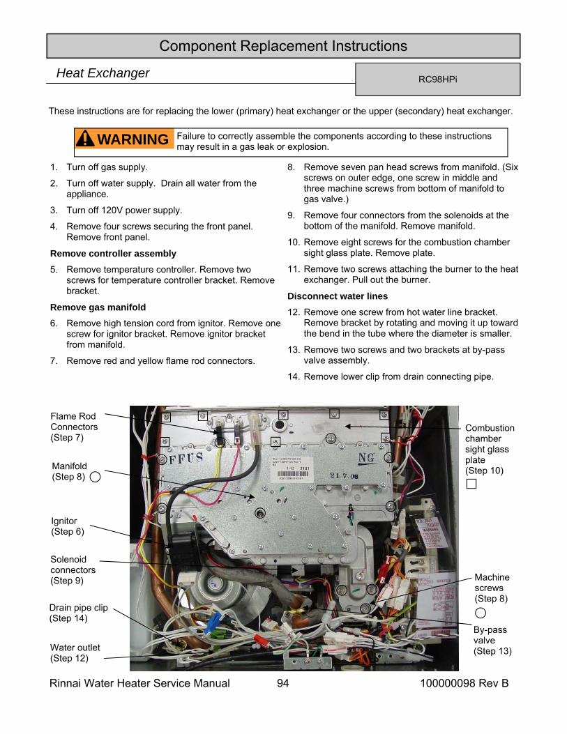
Rinnai Water Heater Service Manual 94 100000098 Rev B
Component Replacement Instructions
RC98HPi Heat Exchanger
1. Turn off gas supply.
2. Turn off water supply. Drain all water from the appliance.
3. Turn off 120V power supply.
4. Remove four screws securing the front panel. Remove front panel.
Remove controller assembly
5. Remove temperature controller. Remove two screws for temperature controller bracket. Remove bracket.
Remove gas manifold
6. Remove high tension cord from ignitor. Remove one screw for ignitor bracket. Remove ignitor bracket from manifold.
7. Remove red and yellow flame rod connectors.
8. Remove seven pan head screws from manifold. (Six screws on outer edge, one screw in middle and three machine screws from bottom of manifold to gas valve.)
9. Remove four connectors from the solenoids at the bottom of the manifold. Remove manifold.
10. Remove eight screws for the combustion chamber sight glass plate. Remove plate.
11. Remove two screws attaching the burner to the heat exchanger. Pull out the burner.
Disconnect water lines
12. Remove one screw from hot water line bracket. Remove bracket by rotating and moving it up toward the bend in the tube where the diameter is smaller.
13. Remove two screws and two brackets at by-pass valve assembly.
14. Remove lower clip from drain connecting pipe.
WARNING Failure to correctly assemble the components according to these instructions may result in a gas leak or explosion.
Manifold (Step 8)
By-pass valve (Step 13) Water outlet
(Step 12)
Ignitor (Step 6)
Flame Rod Connectors (Step 7)
Solenoid connectors (Step 9) Machine
screws (Step 8)
Combustion chamber sight glass plate (Step 10)
Drain pipe clip (Step 14)
These instructions are for replacing the lower (primary) heat exchanger or the upper (secondary) heat exchanger.
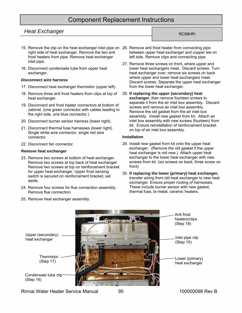
Rinnai Water Heater Service Manual 95 100000098 Rev B
Component Replacement Instructions
RC98HPi Heat Exchanger
15. Remove the clip on the heat exchanger inlet pipe on right side of heat exchanger. Remove the two anti frost heaters from pipe. Remove heat exchanger inlet pipe.
16. Disconnect condensate tube from upper heat exchanger.
Disconnect wire harness
17. Disconnect heat exchanger thermistor (upper left).
18. Remove three anti frost heaters from clips at top of heat exchanger.
19. Disconnect anti frost heater connectors at bottom of cabinet. (one green connector with cables leading to the right side, one blue connector.)
20. Disconnect burner sensor harness (lower right).
21. Disconnect thermal fuse harnesses (lower right). Single white wire connector, single red wire connector.
22. Disconnect fan connector.
Remove heat exchanger 23. Remove two screws at bottom of heat exchanger.
Remove two screws at top back of heat exchanger. Remove two screws at top on reinforcement bracket for upper heat exchanger. Upper frost sensing switch is secured on reinforcement bracket, set aside.
24. Remove four screws for flue connection assembly. Remove flue connection.
25. Remove heat exchanger assembly.
26. Remove anti frost heater from connecting pipe between upper heat exchanger and copper tee on left side. Remove clips and connecting pipe.
27. Remove three screws on front, where upper and lower heat exchangers meet. Discard screws. Turn heat exchanger over; remove six screws on back where upper and lower heat exchangers meet. Discard screws. Separate the upper heat exchanger from the lower heat exchanger.
28. If replacing the upper (secondary) heat exchanger, then remove fourteen screws to separate it from the air inlet box assembly. Discard screws and remove air inlet box assembly. Remove the old gasket from the air inlet box assembly. Install new gasket from kit. Attach air inlet box assembly with new screws (fourteen) from kit. Ensure reinstallation of reinforcement bracket on top of air inlet box assembly.
Installation
29. Install new gasket from kit onto the upper heat exchanger. (Remove the old gasket if the upper heat exchanger is not new.) Attach upper heat exchanger to the lower heat exchanger with new screws from kit. (six screws on back, three screw on front)
30. If replacing the lower (primary) heat exchanger, transfer wiring from old heat exchanger to new heat exchanger. Ensure proper routing of harnesses. These include burner sensor with new gasket, thermal fuse, bi-metal, ceramic heaters.
Upper (secondary) heat exchanger
Lower (primary) heat exchanger
Inlet pipe clip (Step 15)
Thermistor (Step 17)
Anti frost heaters/clips(Step 18)
Condensate tube clip (Step 16)
Rinnai Water Heater Service Manual 96 100000098 Rev B
Component Replacement Instructions
RC98HPi Heat Exchanger
31. If replacing the lower (primary) heat exchanger, transfer parts from old heat exchanger to new heat exchanger. These include fan housing assembly, connecting pipe to upper heat exchanger and copper tee with new o-ring and clip, drain pipe from copper tee.
32. Install heat exchanger assembly in case. Place bottom in cabinet first. Attach with four screws. (two at top back and two on bottom) Attach reinforcement bracket with two screws.
33. Remove old gasket from flue connection assembly. Install new gasket from kit. Attach flue connections assembly with four screws.
Install water and drain lines
34. Install drain connecting pipe with new o-rings and attach with new clips.
35. Install water inlet connecting pipe with new o-rings to upper heat exchanger. Attach with new clip at heat exchanger and at bottom to the by-pass valve with one screw and bracket. Attach the other water line with one screw and bracket.
36. Attach the hot water outlet line to the hot water outlet fitting with one screw and bracket. Reconnect condensate tube to upper heat exchanger.
Reconnect wire harness
37. Reconnect heat exchanger thermistor (upper left).
38. Install three anti frost heaters in clips at top of upper heat exchanger.
39. Reconnect anti frost connectors at bottom of cabinet. One green connector, one blue connector.
40. Reconnect burner sensor harness (lower right).
41. Reconnect thermal fuse harnesses (lower right). Single white wire connector, single red wire connector.
42. Reconnect the fan connector.
Install burner and burner cover plate
43. Install burner assembly with two screws. Replace combustion chamber packing (in kit) on sight glass plate. Install combustion chamber sight glass plate with eight screws.
Install gas manifold
44. Remove packing from gas control assembly. Discard. Install new packing, in kit, on gas control assembly.
45. Remove the packing for manifold. Install new packing, in kit, on gas manifold.
46. Attach the gas manifold with three machine screws at the gas control assembly. Install seven pan head screws on gas manifold to heat exchanger. Attach wire harness ties. (six screws at outer edge, one middle of gas manifold plate)
47. Install four connectors to the solenoids on the gas manifold. (marked)
Reconnect flame rod connectors and igniter 48. Install two flame rod connectors. (marked )
49. Install ignitor bracket with one machine screw.
50. Attach ignitor high tension cord to the electrode.
51. Attach controller bracket with one machine screw and one screw from power wire clamp. Install controller in bracket.
Check 52. Turn on water supply, power supply, and gas
supply. Check for gas and water leaks. Perform operational checks.
53. Install the front panel using four screws.
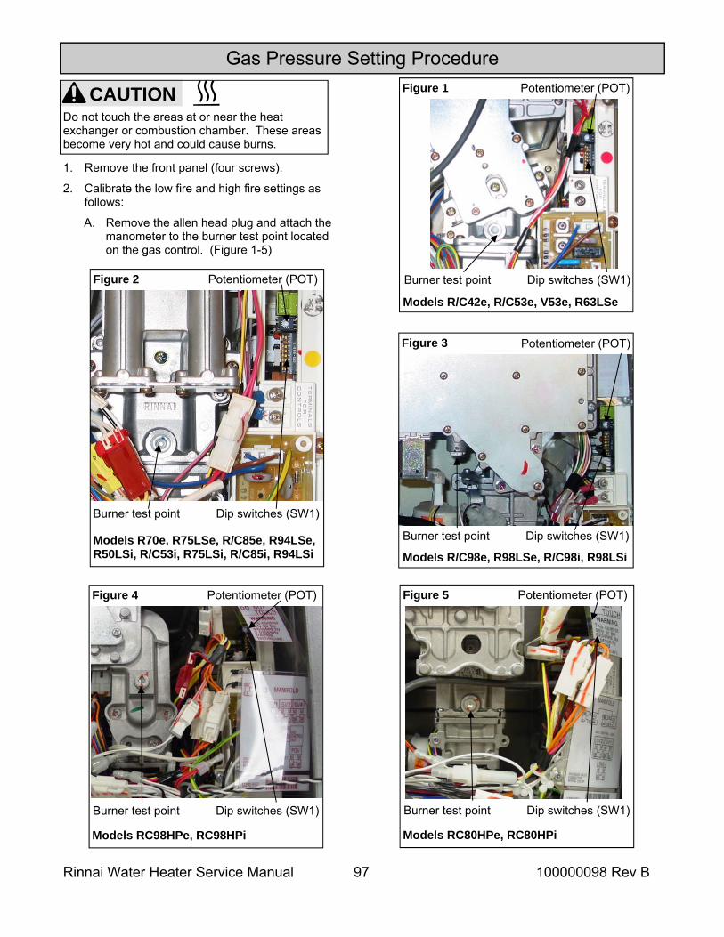
Rinnai Water Heater Service Manual 97 100000098 Rev B
Gas Pressure Setting Procedure
1. Remove the front panel (four screws).
2. Calibrate the low fire and high fire settings as follows:
A. Remove the allen head plug and attach the manometer to the burner test point located on the gas control. (Figure 1-5)
CAUTION Do not touch the areas at or near the heat exchanger or combustion chamber. These areas become very hot and could cause burns.
Models R70e, R75LSe, R/C85e, R94LSe, R50LSi, R/C53i, R75LSi, R/C85i, R94LSi
Figure 2 Potentiometer (POT)
Burner test point Dip switches (SW1)
Models R/C42e, R/C53e, V53e, R63LSe Burner test point Dip switches (SW1)
Figure 1 Potentiometer (POT)
Potentiometer (POT)
Burner test point Dip switches (SW1)
Figure 3
Models R/C98e, R98LSe, R/C98i, R98LSi
Models RC98HPe, RC98HPi
Figure 4 Potentiometer (POT)
Burner test point Dip switches (SW1)
Models RC80HPe, RC80HPi
Figure 5 Potentiometer (POT)
Burner test point Dip switches (SW1)
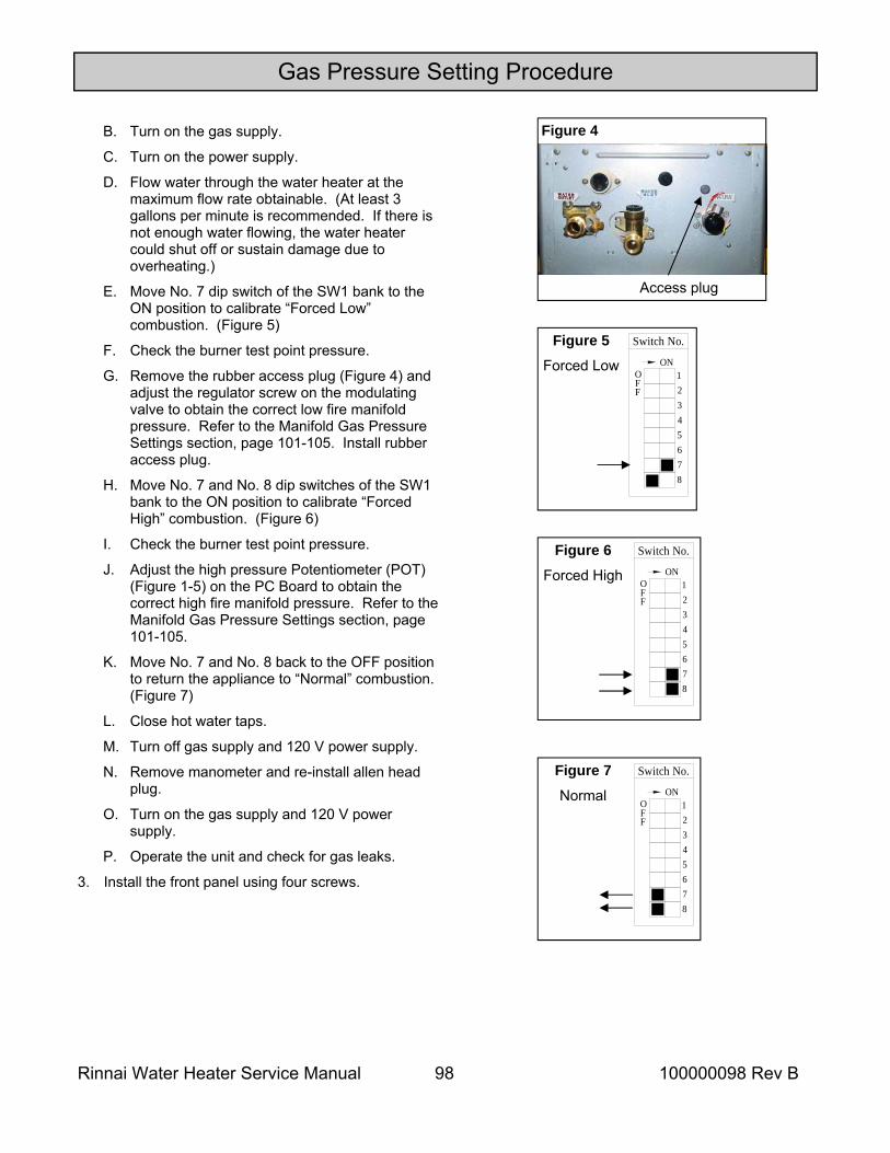
Rinnai Water Heater Service Manual 98 100000098 Rev B
Figure 5 Forced Low
Switch No.
FO
F
8
5
76
43
ON12
Figure 6 Forced High
Switch No.
FO
F
8
5
76
43
ON12
Figure 7 Normal
Switch No.
FO
F
8
5
76
43
ON12
Figure 4
Access plug
B. Turn on the gas supply.
C. Turn on the power supply.
D. Flow water through the water heater at the maximum flow rate obtainable. (At least 3 gallons per minute is recommended. If there is not enough water flowing, the water heater could shut off or sustain damage due to overheating.)
E. Move No. 7 dip switch of the SW1 bank to the ON position to calibrate “Forced Low” combustion. (Figure 5)
F. Check the burner test point pressure.
G. Remove the rubber access plug (Figure 4) and adjust the regulator screw on the modulating valve to obtain the correct low fire manifold pressure. Refer to the Manifold Gas Pressure Settings section, page 101-105. Install rubber access plug.
H. Move No. 7 and No. 8 dip switches of the SW1 bank to the ON position to calibrate “Forced High” combustion. (Figure 6)
I. Check the burner test point pressure.
J. Adjust the high pressure Potentiometer (POT) (Figure 1-5) on the PC Board to obtain the correct high fire manifold pressure. Refer to the Manifold Gas Pressure Settings section, page 101-105.
K. Move No. 7 and No. 8 back to the OFF position to return the appliance to “Normal” combustion. (Figure 7)
L. Close hot water taps.
M. Turn off gas supply and 120 V power supply.
N. Remove manometer and re-install allen head plug.
O. Turn on the gas supply and 120 V power supply.
P. Operate the unit and check for gas leaks.
3. Install the front panel using four screws.
Gas Pressure Setting Procedure
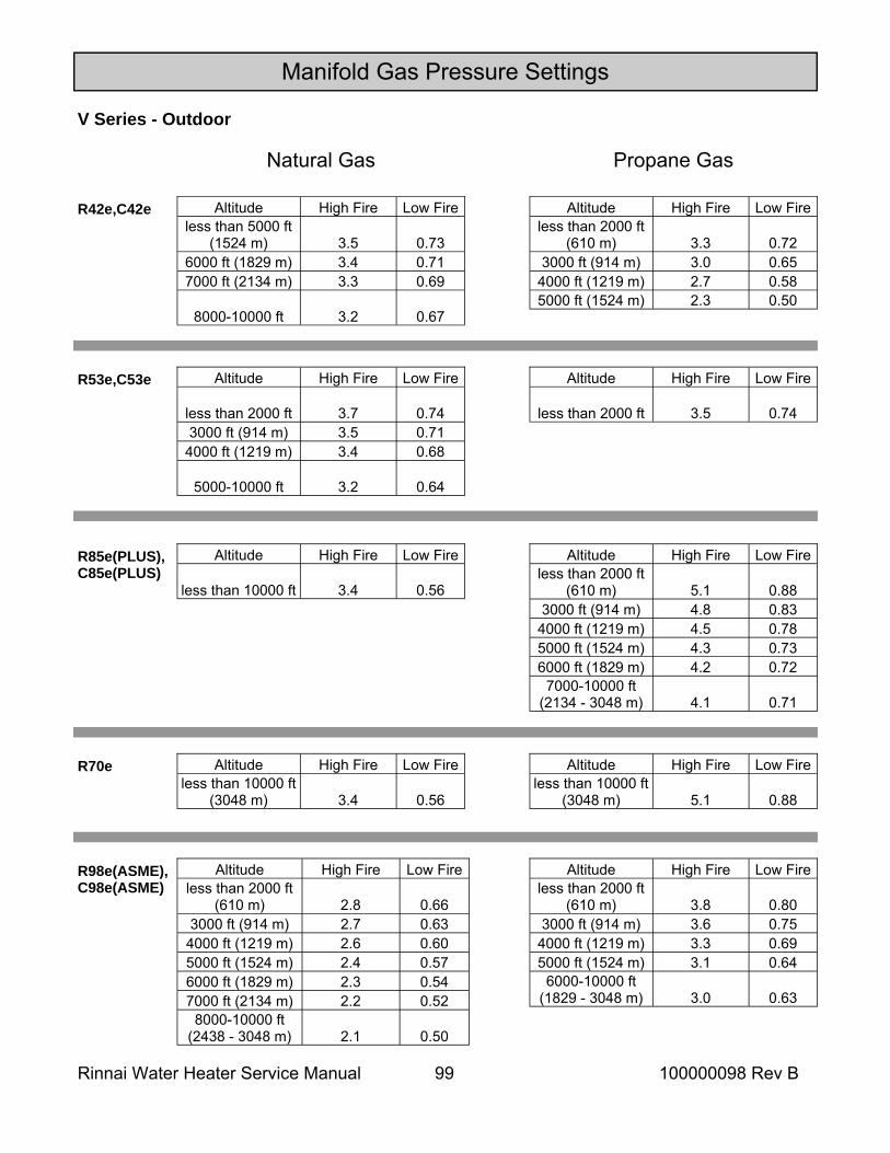
Rinnai Water Heater Service Manual 99 100000098 Rev B
Manifold Gas Pressure Settings
V Series - Outdoor
Altitude High Fire Low Fire less than 5000 ft
(1524 m) 3.5 0.73 6000 ft (1829 m) 3.4 0.71 7000 ft (2134 m) 3.3 0.69
8000-10000 ft 3.2 0.67
R42e,C42e Altitude High Fire Low Fire less than 2000 ft
(610 m) 3.3 0.72 3000 ft (914 m) 3.0 0.65
4000 ft (1219 m) 2.7 0.58 5000 ft (1524 m) 2.3 0.50
Natural Gas Propane Gas
R53e,C53e Altitude High Fire Low Fire
less than 2000 ft 3.7 0.74 3000 ft (914 m) 3.5 0.71
4000 ft (1219 m) 3.4 0.68
5000-10000 ft 3.2 0.64
Altitude High Fire Low Fire
less than 2000 ft 3.5 0.74
R85e(PLUS), C85e(PLUS)
Altitude High Fire Low Fire less than 2000 ft
(610 m) 5.1 0.88 3000 ft (914 m) 4.8 0.83
4000 ft (1219 m) 4.5 0.78 5000 ft (1524 m) 4.3 0.73 6000 ft (1829 m) 4.2 0.72
7000-10000 ft(2134 - 3048 m) 4.1 0.71
Altitude High Fire Low Fire
less than 10000 ft 3.4 0.56
R70e Altitude High Fire Low Fire less than 10000 ft
(3048 m) 3.4 0.56
Altitude High Fire Low Fire less than 10000 ft
(3048 m) 5.1 0.88
R98e(ASME), C98e(ASME)
Altitude High Fire Low Fire less than 2000 ft
(610 m) 2.8 0.66 3000 ft (914 m) 2.7 0.63
4000 ft (1219 m) 2.6 0.60 5000 ft (1524 m) 2.4 0.57 6000 ft (1829 m) 2.3 0.54 7000 ft (2134 m) 2.2 0.52
8000-10000 ft(2438 - 3048 m) 2.1 0.50
Altitude High Fire Low Fire less than 2000 ft
(610 m) 3.8 0.80 3000 ft (914 m) 3.6 0.75
4000 ft (1219 m) 3.3 0.69 5000 ft (1524 m) 3.1 0.64
6000-10000 ft(1829 - 3048 m) 3.0 0.63
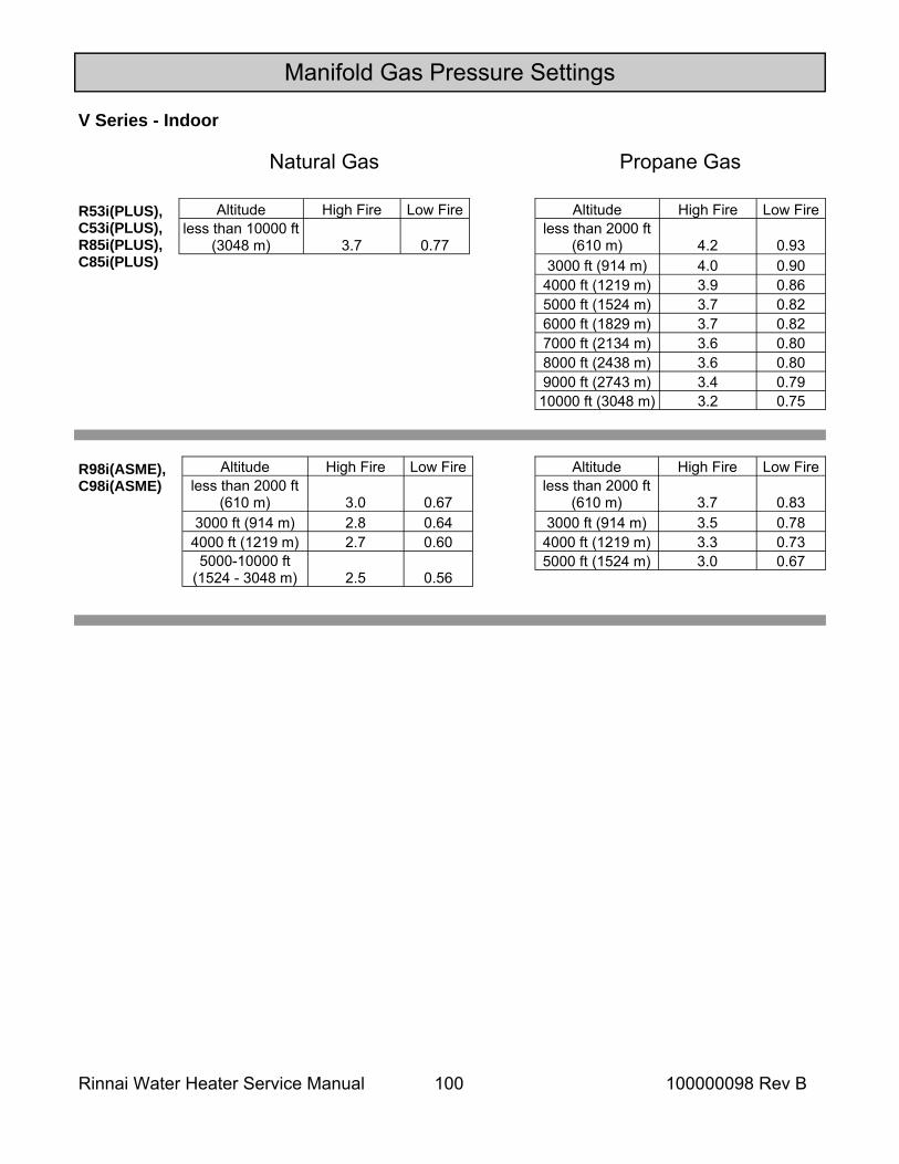
Rinnai Water Heater Service Manual 100 100000098 Rev B
Manifold Gas Pressure Settings
V Series - Indoor
Natural Gas Propane Gas
R53i(PLUS), C53i(PLUS), R85i(PLUS), C85i(PLUS)
Altitude High Fire Low Fire less than 10000 ft
(3048 m) 3.7 0.77
Altitude High Fire Low Fire less than 2000 ft
(610 m) 4.2 0.93 3000 ft (914 m) 4.0 0.90
4000 ft (1219 m) 3.9 0.86 5000 ft (1524 m) 3.7 0.82 6000 ft (1829 m) 3.7 0.82 7000 ft (2134 m) 3.6 0.80 8000 ft (2438 m) 3.6 0.80 9000 ft (2743 m) 3.4 0.79 10000 ft (3048 m) 3.2 0.75
R98i(ASME), C98i(ASME)
Altitude High Fire Low Fire less than 2000 ft
(610 m) 3.0 0.67 3000 ft (914 m) 2.8 0.64
4000 ft (1219 m) 2.7 0.60 5000-10000 ft
(1524 - 3048 m) 2.5 0.56
Altitude High Fire Low Fire less than 2000 ft
(610 m) 3.7 0.83 3000 ft (914 m) 3.5 0.78 4000 ft (1219 m) 3.3 0.73 5000 ft (1524 m) 3.0 0.67
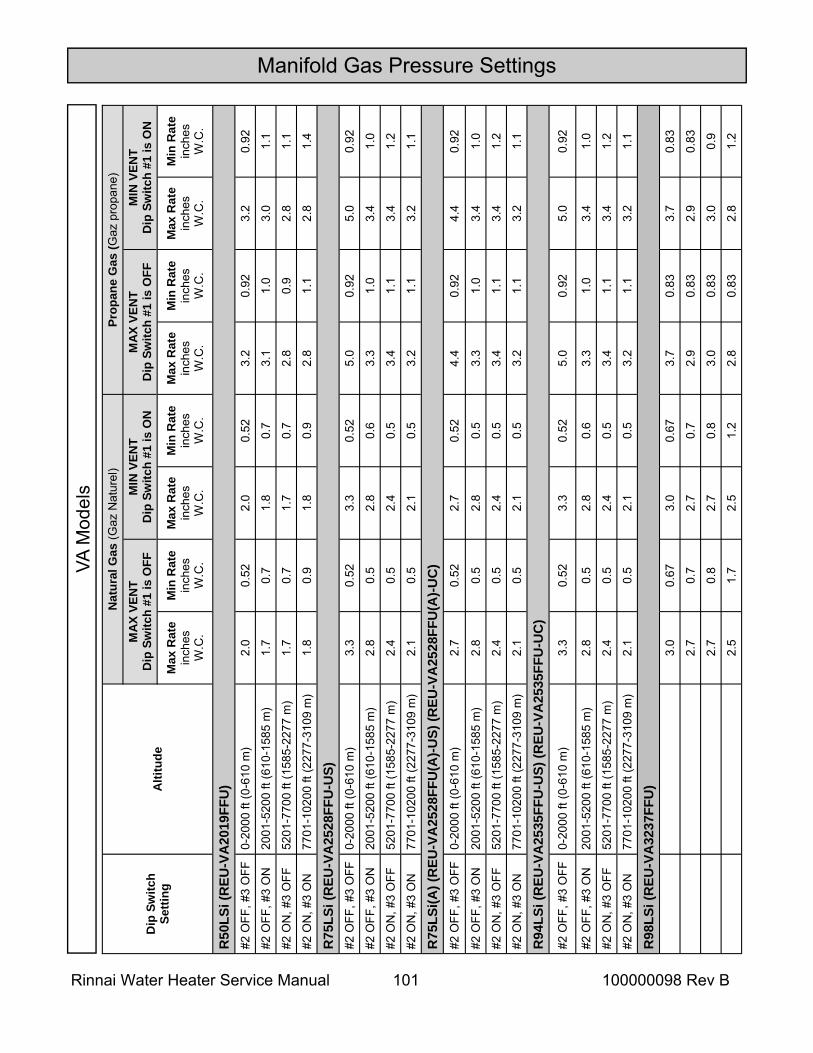
Rinnai Water Heater Service Manual 101 100000098 Rev B
Manifold Gas Pressure Settings
Dip
Sw
itch
Setti
ng
Alti
tude
Nat
ural
Gas
(Gaz
Nat
urel
) Pr
opan
e G
as (G
az p
ropa
ne)
MA
X VE
NT
D
ip S
witc
h #1
is O
FF
MIN
VEN
T D
ip S
witc
h #1
is O
N
MA
X VE
NT
D
ip S
witc
h #1
is O
FF
MIN
VEN
T D
ip S
witc
h #1
is O
N
Max
Rat
e in
ches
W
.C.
Min
Rat
e in
ches
W
.C.
Max
Rat
e in
ches
W
.C.
Min
Rat
e in
ches
W
.C.
Max
Rat
e in
ches
W
.C.
Min
Rat
e in
ches
W
.C.
Max
Rat
e in
ches
W
.C.
Min
Rat
e in
ches
W
.C.
R50
LSi (
REU
-VA
2019
FFU
)
#2 O
FF, #
3 O
FF
0-20
00 ft
(0-6
10 m
) 2.
0 0.
52
2.0
0.52
3.
2 0.
92
3.2
0.92
#2 O
FF, #
3 O
N
2001
-520
0 ft
(610
-158
5 m
) 1.
7 0.
7 1.
8 0.
7 3.
1 1.
0 3.
0 1.
1
#2 O
N, #
3 O
FF
5201
-770
0 ft
(158
5-22
77 m
) 1.
7 0.
7 1.
7 0.
7 2.
8 0.
9 2.
8 1.
1
#2 O
N, #
3 O
N
7701
-102
00 ft
(227
7-31
09 m
) 1.
8 0.
9 1.
8 0.
9 2.
8 1.
1 2.
8 1.
4
R75
LSi (
REU
-VA
2528
FFU
-US)
#2
OFF
, #3
OFF
0-
2000
ft (0
-610
m)
3.3
0.52
3.
3 0.
52
5.0
0.92
5.
0 0.
92
#2 O
FF, #
3 O
N
2001
-520
0 ft
(610
-158
5 m
) 2.
8 0.
5 2.
8 0.
6 3.
3 1.
0 3.
4 1.
0
#2 O
N, #
3 O
FF
5201
-770
0 ft
(158
5-22
77 m
) 2.
4 0.
5 2.
4 0.
5 3.
4 1.
1 3.
4 1.
2
#2 O
N, #
3 O
N
7701
-102
00 ft
(227
7-31
09 m
) 2.
1 0.
5 2.
1 0.
5 3.
2 1.
1 3.
2 1.
1
R75
LSi(A
) (R
EU-V
A25
28FF
U(A
)-US)
(REU
-VA
2528
FFU
(A)-U
C)
#2
OFF
, #3
OFF
0-
2000
ft (0
-610
m)
2.7
0.52
2.
7 0.
52
4.4
0.92
4.
4 0.
92
#2 O
FF, #
3 O
N
2001
-520
0 ft
(610
-158
5 m
) 2.
8 0.
5 2.
8 0.
5 3.
3 1.
0 3.
4 1.
0
#2 O
N, #
3 O
FF
5201
-770
0 ft
(158
5-22
77 m
) 2.
4 0.
5 2.
4 0.
5 3.
4 1.
1 3.
4 1.
2
#2 O
N, #
3 O
N
7701
-102
00 ft
(227
7-31
09 m
) 2.
1 0.
5 2.
1 0.
5 3.
2 1.
1 3.
2 1.
1
R94
LSi (
REU
-VA
2535
FFU
-US)
(REU
-VA
2535
FFU
-UC
)
#2 O
FF, #
3 O
FF
0-20
00 ft
(0-6
10 m
) 3.
3 0.
52
3.3
0.52
5.
0 0.
92
5.0
0.92
#2 O
FF, #
3 O
N
2001
-520
0 ft
(610
-158
5 m
) 2.
8 0.
5 2.
8 0.
6 3.
3 1.
0 3.
4 1.
0
#2 O
N, #
3 O
FF
5201
-770
0 ft
(158
5-22
77 m
) 2.
4 0.
5 2.
4 0.
5 3.
4 1.
1 3.
4 1.
2
#2 O
N, #
3 O
N
7701
-102
00 ft
(227
7-31
09 m
) 2.
1 0.
5 2.
1 0.
5 3.
2 1.
1 3.
2 1.
1
3.0
0.67
3.
0 0.
67
3.7
0.83
3.
7 0.
83
2.7
0.7
2.7
0.7
2.9
0.83
2.
9 0.
83
2.7
0.8
2.7
0.8
3.0
0.83
3.
0 0.
9
2.5
1.7
2.5
1.2
2.8
0.83
2.
8 1.
2
R98
LSi (
REU
-VA
3237
FFU
)
VA M
odel
s
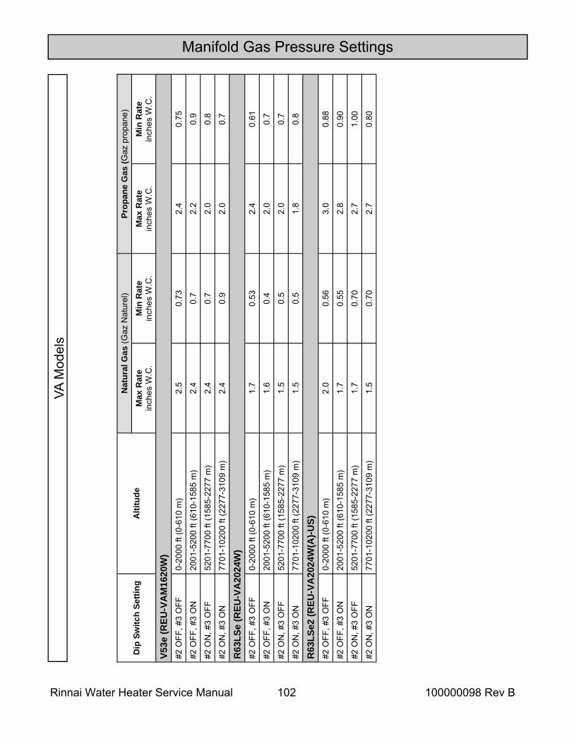
Rinnai Water Heater Service Manual 102 100000098 Rev B
Dip
Sw
itch
Setti
ng
Alti
tude
N
atur
al G
as (G
az N
atur
el)
Prop
ane
Gas
(Gaz
pro
pane
) M
ax R
ate
inch
es W
.C.
Min
Rat
e in
ches
W.C
. M
ax R
ate
inch
es W
.C.
Min
Rat
e in
ches
W.C
.
V53e
(REU
-VA
M16
20W
) #2
OFF
, #3
OFF
0-
2000
ft (0
-610
m)
2.5
0.73
2.
4 0.
75
#2 O
FF, #
3 O
N
2001
-520
0 ft
(610
-158
5 m
) 2.
4 0.
7 2.
2 0.
9
#2 O
N, #
3 O
FF
5201
-770
0 ft
(158
5-22
77 m
) 2.
4 0.
7 2.
0 0.
8
#2 O
N, #
3 O
N
7701
-102
00 ft
(227
7-31
09 m
) 2.
4 0.
9 2.
0 0.
7
R63
LSe
(REU
-VA
2024
W)
#2 O
FF, #
3 O
FF
0-20
00 ft
(0-6
10 m
) 1.
7 0.
53
2.4
0.61
#2 O
FF, #
3 O
N
2001
-520
0 ft
(610
-158
5 m
) 1.
6 0.
4 2.
0 0.
7
#2 O
N, #
3 O
FF
5201
-770
0 ft
(158
5-22
77 m
) 1.
5 0.
5 2.
0 0.
7
#2 O
N, #
3 O
N
7701
-102
00 ft
(227
7-31
09 m
) 1.
5 0.
5 1.
8 0.
8
R63
LSe2
(REU
-VA
2024
W(A
)-US)
#2
OFF
, #3
OFF
0-
2000
ft (0
-610
m)
2.0
0.56
3.
0 0.
88
#2 O
FF, #
3 O
N
2001
-520
0 ft
(610
-158
5 m
) 1.
7 0.
55
2.8
0.90
#2 O
N, #
3 O
FF
5201
-770
0 ft
(158
5-22
77 m
) 1.
7 0.
70
2.7
1.00
#2 O
N, #
3 O
N
7701
-102
00 ft
(227
7-31
09 m
) 1.
5 0.
70
2.7
0.80
Manifold Gas Pressure Settings VA
Mod
els
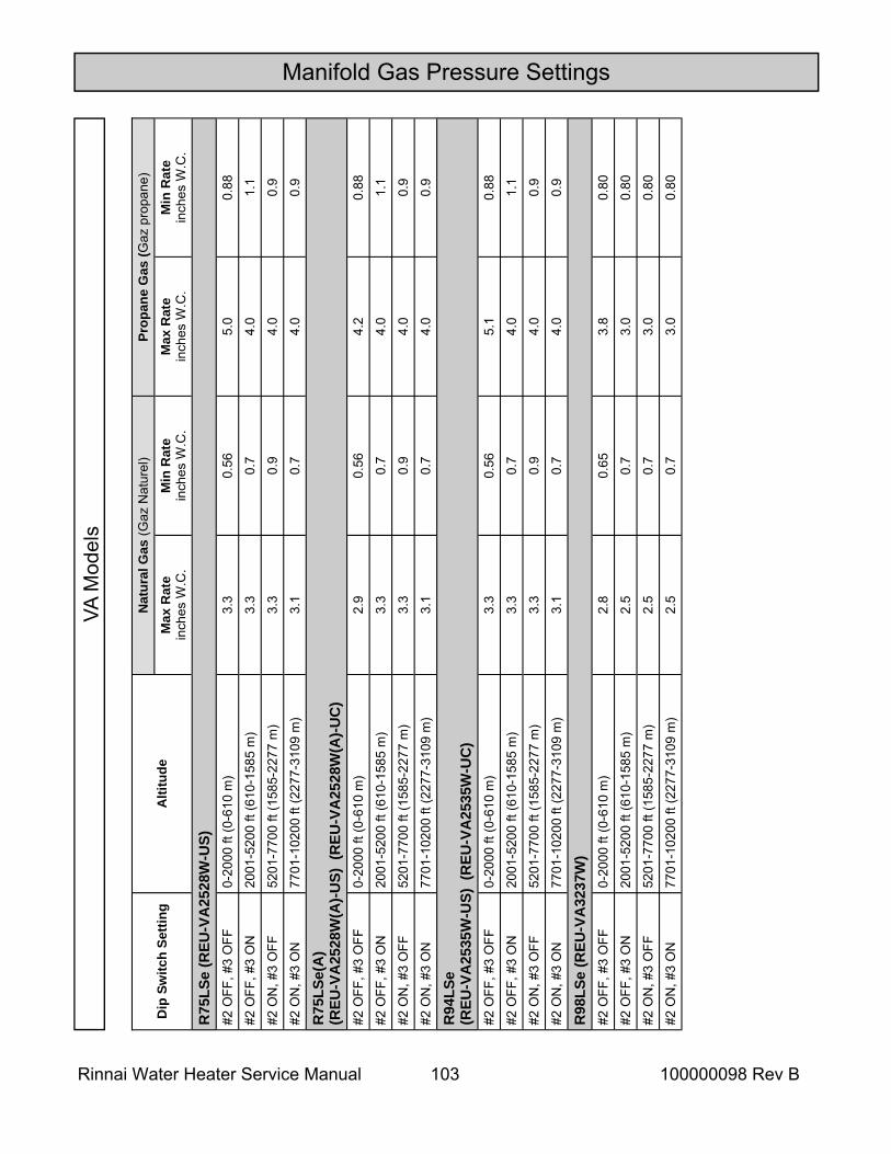
Rinnai Water Heater Service Manual 103 100000098 Rev B
Manifold Gas Pressure Settings
Dip
Sw
itch
Setti
ng
Alti
tude
N
atur
al G
as (G
az N
atur
el)
Prop
ane
Gas
(Gaz
pro
pane
) M
ax R
ate
inch
es W
.C.
Min
Rat
e in
ches
W.C
. M
ax R
ate
inch
es W
.C.
Min
Rat
e in
ches
W.C
.
R75
LSe
(REU
-VA
2528
W-U
S)
#2 O
FF, #
3 O
FF
0-20
00 ft
(0-6
10 m
) 3.
3 0.
56
5.0
0.88
#2 O
FF, #
3 O
N
2001
-520
0 ft
(610
-158
5 m
) 3.
3 0.
7 4.
0 1.
1
#2 O
N, #
3 O
FF
5201
-770
0 ft
(158
5-22
77 m
) 3.
3 0.
9 4.
0 0.
9
#2 O
N, #
3 O
N
7701
-102
00 ft
(227
7-31
09 m
) 3.
1 0.
7 4.
0 0.
9
R75
LSe(
A)
(REU
-VA
2528
W(A
)-US)
(R
EU-V
A25
28W
(A)-U
C)
#2
OFF
, #3
OFF
0-
2000
ft (0
-610
m)
2.9
0.56
4.
2 0.
88
#2 O
FF, #
3 O
N
2001
-520
0 ft
(610
-158
5 m
) 3.
3 0.
7 4.
0 1.
1
#2 O
N, #
3 O
FF
5201
-770
0 ft
(158
5-22
77 m
) 3.
3 0.
9 4.
0 0.
9
#2 O
N, #
3 O
N
7701
-102
00 ft
(227
7-31
09 m
) 3.
1 0.
7 4.
0 0.
9
R94
LSe
(REU
-VA
2535
W-U
S) (
REU
-VA
2535
W-U
C)
#2 O
FF, #
3 O
FF
0-20
00 ft
(0-6
10 m
) 3.
3 0.
56
5.1
0.88
#2 O
FF, #
3 O
N
2001
-520
0 ft
(610
-158
5 m
) 3.
3 0.
7 4.
0 1.
1
#2 O
N, #
3 O
FF
5201
-770
0 ft
(158
5-22
77 m
) 3.
3 0.
9 4.
0 0.
9
#2 O
N, #
3 O
N
7701
-102
00 ft
(227
7-31
09 m
) 3.
1 0.
7 4.
0 0.
9
#2 O
FF, #
3 O
FF
0-20
00 ft
(0-6
10 m
) 2.
8 0.
65
3.8
0.80
#2 O
FF, #
3 O
N
2001
-520
0 ft
(610
-158
5 m
) 2.
5 0.
7 3.
0 0.
80
#2 O
N, #
3 O
FF
5201
-770
0 ft
(158
5-22
77 m
) 2.
5 0.
7 3.
0 0.
80
#2 O
N, #
3 O
N
7701
-102
00 ft
(227
7-31
09 m
) 2.
5 0.
7 3.
0 0.
80
R98
LSe
(REU
-VA
3237
W)
VA M
odel
s
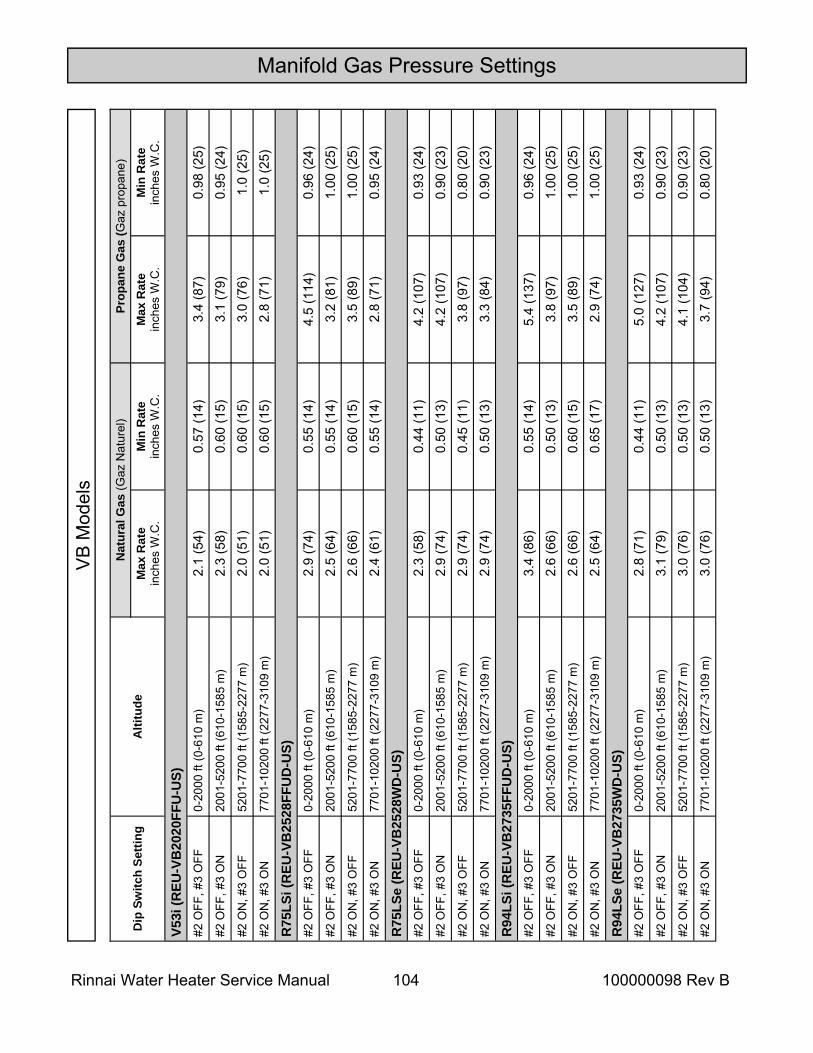
Rinnai Water Heater Service Manual 104 100000098 Rev B
Manifold Gas Pressure Settings
Dip
Sw
itch
Setti
ng
Alti
tude
N
atur
al G
as (G
az N
atur
el)
Prop
ane
Gas
(Gaz
pro
pane
) M
ax R
ate
inch
es W
.C.
Min
Rat
e in
ches
W.C
. M
ax R
ate
inch
es W
.C.
Min
Rat
e in
ches
W.C
.
V53i
(REU
-VB
2020
FFU
-US)
#2
OFF
, #3
OFF
0-
2000
ft (0
-610
m)
2.1
(54)
0.
57 (1
4)
3.4
(87)
0.
98 (2
5)
#2 O
FF, #
3 O
N
2001
-520
0 ft
(610
-158
5 m
) 2.
3 (5
8)
0.60
(15)
3.
1 (7
9)
0.95
(24)
#2
ON
, #3
OFF
52
01-7
700
ft (1
585-
2277
m)
2.0
(51)
0.
60 (1
5)
3.0
(76)
1.
0 (2
5)
#2 O
N, #
3 O
N
7701
-102
00 ft
(227
7-31
09 m
) 2.
0 (5
1)
0.60
(15)
2.
8 (7
1)
1.0
(25)
R
75LS
i (R
EU-V
B25
28FF
UD
-US)
#2
OFF
, #3
OFF
0-
2000
ft (0
-610
m)
2.9
(74)
0.
55 (1
4)
4.5
(114
) 0.
96 (2
4)
#2 O
FF, #
3 O
N
2001
-520
0 ft
(610
-158
5 m
) 2.
5 (6
4)
0.55
(14)
3.
2 (8
1)
1.00
(25)
#2
ON
, #3
OFF
52
01-7
700
ft (1
585-
2277
m)
2.6
(66)
0.
60 (1
5)
3.5
(89)
1.
00 (2
5)
#2 O
N, #
3 O
N
7701
-102
00 ft
(227
7-31
09 m
) 2.
4 (6
1)
0.55
(14)
2.
8 (7
1)
0.95
(24)
R
75LS
e (R
EU-V
B25
28W
D-U
S)
#2 O
FF, #
3 O
FF
0-20
00 ft
(0-6
10 m
) 2.
3 (5
8)
0.44
(11)
4.
2 (1
07)
0.93
(24)
#2
OFF
, #3
ON
20
01-5
200
ft (6
10-1
585
m)
2.9
(74)
0.
50 (1
3)
4.2
(107
) 0.
90 (2
3)
#2 O
N, #
3 O
FF
5201
-770
0 ft
(158
5-22
77 m
) 2.
9 (7
4)
0.45
(11)
3.
8 (9
7)
0.80
(20)
#2
ON
, #3
ON
77
01-1
0200
ft (2
277-
3109
m)
2.9
(74)
0.
50 (1
3)
3.3
(84)
0.
90 (2
3)
R94
LSi (
REU
-VB
2735
FFU
D-U
S)
#2 O
FF, #
3 O
FF
0-20
00 ft
(0-6
10 m
) 3.
4 (8
6)
0.55
(14)
5.
4 (1
37)
0.96
(24)
#2
OFF
, #3
ON
20
01-5
200
ft (6
10-1
585
m)
2.6
(66)
0.
50 (1
3)
3.8
(97)
1.
00 (2
5)
#2 O
N, #
3 O
FF
5201
-770
0 ft
(158
5-22
77 m
) 2.
6 (6
6)
0.60
(15)
3.
5 (8
9)
1.00
(25)
#2
ON
, #3
ON
77
01-1
0200
ft (2
277-
3109
m)
2.5
(64)
0.
65 (1
7)
2.9
(74)
1.
00 (2
5)
#2 O
FF, #
3 O
FF
0-20
00 ft
(0-6
10 m
) 2.
8 (7
1)
0.44
(11)
5.
0 (1
27)
0.93
(24)
#2
OFF
, #3
ON
20
01-5
200
ft (6
10-1
585
m)
3.1
(79)
0.
50 (1
3)
4.2
(107
) 0.
90 (2
3)
#2 O
N, #
3 O
FF
5201
-770
0 ft
(158
5-22
77 m
) 3.
0 (7
6)
0.50
(13)
4.
1 (1
04)
0.90
(23)
#2
ON
, #3
ON
77
01-1
0200
ft (2
277-
3109
m)
3.0
(76)
0.
50 (1
3)
3.7
(94)
0.
80 (2
0)
R94
LSe
(REU
-VB
2735
WD
-US)
VB
Mod
els
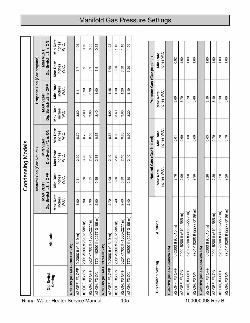
Rinnai Water Heater Service Manual 105 100000098 Rev B
Manifold Gas Pressure Settings
Dip
Sw
itch
Setti
ng
Alti
tude
Nat
ural
Gas
(Gaz
Nat
urel
) Pr
opan
e G
as (G
az p
ropa
ne)
MA
X VE
NT
D
ip S
witc
h #1
is O
FF
MIN
VEN
T D
ip S
witc
h #1
is O
N
MA
X VE
NT
D
ip S
witc
h #1
is O
FF
MIN
VEN
T D
ip S
witc
h #1
is O
N
Max
Rat
e in
ches
W
.C.
Min
Rat
e in
ches
W
.C.
Max
Rat
e in
ches
W
.C.
Min
Rat
e in
ches
W
.C.
Max
Rat
e in
ches
W
.C.
Min
Rat
e in
ches
W
.C.
Max
Rat
e in
ches
W
.C.
Min
Rat
e in
ches
W
.C.
RC
80H
Pi (R
EU-K
A25
30FF
UD
-US)
#2 O
FF, #
3 O
FF
0-20
00 ft
(0-6
10 m
) 3.
00
0.81
2.
90
0.70
3.
80
1.11
3.
7 1.
06
#2 O
FF, #
3 O
N
2001
-520
0 ft
(610
-158
5 m
) 2.
90
0.70
3.
20
0.70
3.
80
0.90
3.
9 0.
70
#2 O
N, #
3 O
FF
5201
-770
0 ft
(158
5-22
77 m
) 2.
90
0.55
2.
90
0.55
3.
80
0.90
3.
9 0.
55
#2 O
N, #
3 O
N
7701
-102
00 ft
(227
7-31
09 m
) 2.
90
0.55
2.
85
0.55
3.
40
1.00
3.
5 0.
55
RC
98H
Pi (R
EU-K
A32
37FF
UD
-US)
#2 O
FF, #
3 O
FF
0-20
00 ft
(0-6
10 m
) 2.
70
1.08
2.
40
0.85
4.
00
1.46
3.
60
1.22
#2 O
FF, #
3 O
N
2001
-520
0 ft
(610
-158
5 m
) 2.
40
0.80
2.
40
0.80
3.
60
1.30
3.
30
1.10
#2 O
N, #
3 O
FF
5201
-770
0 ft
(158
5-22
77 m
) 2.
40
0.80
2.
40
0.80
3.
60
1.20
3.
30
1.10
#2 O
N, #
3 O
N
7701
-102
00 ft
(227
7-31
09 m
) 2.
40
0.80
2.
40
0.90
3.
20
1.10
3.
20
1.00
Dip
Sw
itch
Setti
ng
Alti
tude
N
atur
al G
as (G
az N
atur
el)
Prop
ane
Gas
(Gaz
pro
pane
) M
ax R
ate
inch
es W
.C.
Min
Rat
e in
ches
W.C
. M
ax R
ate
inch
es W
.C.
Min
Rat
e in
ches
W.C
. R
C80
HPe
(REU
-KA
2530
WD
-US)
#2 O
FF, #
3 O
FF
0-20
00 ft
(0-6
10 m
) 2.
70
0.61
3.
60
0.92
#2 O
FF, #
3 O
N
2001
-520
0 ft
(610
-158
5 m
) 2.
90
0.60
3.
70
1.00
#2 O
N, #
3 O
FF
5201
-770
0 ft
(158
5-22
77 m
) 2.
90
0.60
3.
70
1.00
#2 O
N, #
3 O
N
7701
-102
00 ft
(227
7-31
09 m
) 2.
90
0.60
3.
40
1.00
RC
98H
Pe (R
EU-K
A32
37W
D-U
S)
#2 O
FF, #
3 O
FF
0-20
00 ft
(0-6
10 m
) 2.
20
0.63
3.
10
1.00
#2 O
FF, #
3 O
N
2001
-520
0 ft
(610
-158
5 m
) 2.
20
0.70
3.
10
1.00
#2 O
N, #
3 O
FF
5201
-770
0 ft
(158
5-22
77 m
) 2.
20
0.70
3.
10
1.00
#2 O
N, #
3 O
N
7701
-102
00 ft
(227
7-31
09 m
) 2.
20
0.70
3.
00
1.00
Con
dens
ing
Mod
els
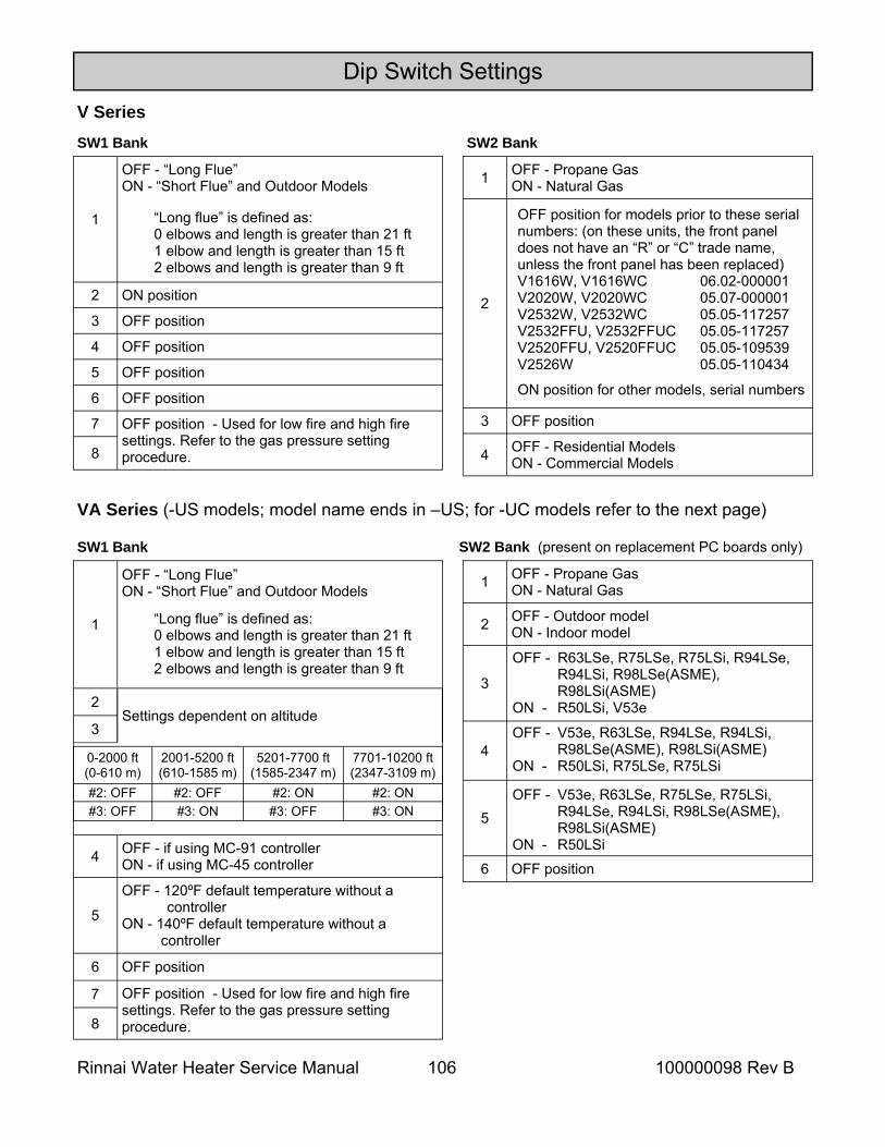
Rinnai Water Heater Service Manual 106 100000098 Rev B
0-2000 ft (0-610 m)
2001-5200 ft (610-1585 m)
5201-7700 ft (1585-2347 m)
7701-10200 ft (2347-3109 m)
#2: OFF #2: OFF #2: ON #2: ON #3: OFF #3: ON #3: OFF #3: ON
Dip Switch Settings
1
OFF - “Long Flue” ON - “Short Flue” and Outdoor Models
2 ON position
3 OFF position
4 OFF position
5 OFF position
6 OFF position
7
8
OFF position - Used for low fire and high fire settings. Refer to the gas pressure setting procedure.
V Series SW1 Bank SW2 Bank
VA Series (-US models; model name ends in –US; for -UC models refer to the next page)
SW1 Bank SW2 Bank (present on replacement PC boards only)
OFF - V53e, R63LSe, R75LSe, R75LSi, R94LSe, R94LSi, R98LSe(ASME), R98LSi(ASME)
ON - R50LSi
OFF - V53e, R63LSe, R94LSe, R94LSi, R98LSe(ASME), R98LSi(ASME)
ON - R50LSi, R75LSe, R75LSi
OFF - R63LSe, R75LSe, R75LSi, R94LSe, R94LSi, R98LSe(ASME), R98LSi(ASME)
ON - R50LSi, V53e
1 OFF - Propane Gas ON - Natural Gas
2 OFF - Outdoor model ON - Indoor model
3
4
5
6 OFF position
“Long flue” is defined as: 0 elbows and length is greater than 21 ft 1 elbow and length is greater than 15 ft 2 elbows and length is greater than 9 ft
1
OFF - “Long Flue” ON - “Short Flue” and Outdoor Models
2 Settings dependent on altitude
3
4 OFF - if using MC-91 controller ON - if using MC-45 controller
5
OFF - 120ºF default temperature without a controller
ON - 140ºF default temperature without a controller
6 OFF position
7 OFF position - Used for low fire and high fire settings. Refer to the gas pressure setting procedure. 8
“Long flue” is defined as: 0 elbows and length is greater than 21 ft 1 elbow and length is greater than 15 ft 2 elbows and length is greater than 9 ft
OFF position for models prior to these serial numbers: (on these units, the front panel does not have an “R” or “C” trade name, unless the front panel has been replaced) V1616W, V1616WC 06.02-000001 V2020W, V2020WC 05.07-000001 V2532W, V2532WC 05.05-117257 V2532FFU, V2532FFUC 05.05-117257 V2520FFU, V2520FFUC 05.05-109539 V2526W 05.05-110434
ON position for other models, serial numbers
1 OFF - Propane Gas ON - Natural Gas
2
3 OFF position
4 OFF - Residential Models ON - Commercial Models
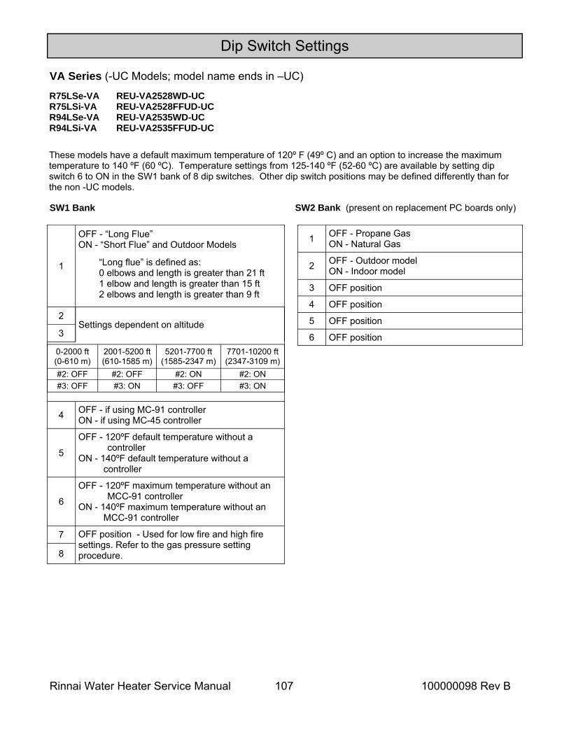
Rinnai Water Heater Service Manual 107 100000098 Rev B
Dip Switch Settings
0-2000 ft (0-610 m)
2001-5200 ft (610-1585 m)
5201-7700 ft (1585-2347 m)
7701-10200 ft (2347-3109 m)
#2: OFF #2: OFF #2: ON #2: ON #3: OFF #3: ON #3: OFF #3: ON
VA Series (-UC Models; model name ends in –UC)
SW1 Bank SW2 Bank (present on replacement PC boards only)
1 OFF - Propane Gas ON - Natural Gas
2 OFF - Outdoor model ON - Indoor model
3 OFF position
4 OFF position
5 OFF position
6 OFF position
1
OFF - “Long Flue” ON - “Short Flue” and Outdoor Models
2 Settings dependent on altitude
3
4 OFF - if using MC-91 controller ON - if using MC-45 controller
5
OFF - 120ºF default temperature without a controller
ON - 140ºF default temperature without a controller
6
OFF - 120ºF maximum temperature without an MCC-91 controller
ON - 140ºF maximum temperature without an MCC-91 controller
7 OFF position - Used for low fire and high fire settings. Refer to the gas pressure setting procedure. 8
“Long flue” is defined as: 0 elbows and length is greater than 21 ft 1 elbow and length is greater than 15 ft 2 elbows and length is greater than 9 ft
These models have a default maximum temperature of 120º F (49º C) and an option to increase the maximum temperature to 140 ºF (60 ºC). Temperature settings from 125-140 ºF (52-60 ºC) are available by setting dip switch 6 to ON in the SW1 bank of 8 dip switches. Other dip switch positions may be defined differently than for the non -UC models.
R75LSe-VA REU-VA2528WD-UC R75LSi-VA REU-VA2528FFUD-UC R94LSe-VA REU-VA2535WD-UC R94LSi-VA REU-VA2535FFUD-UC
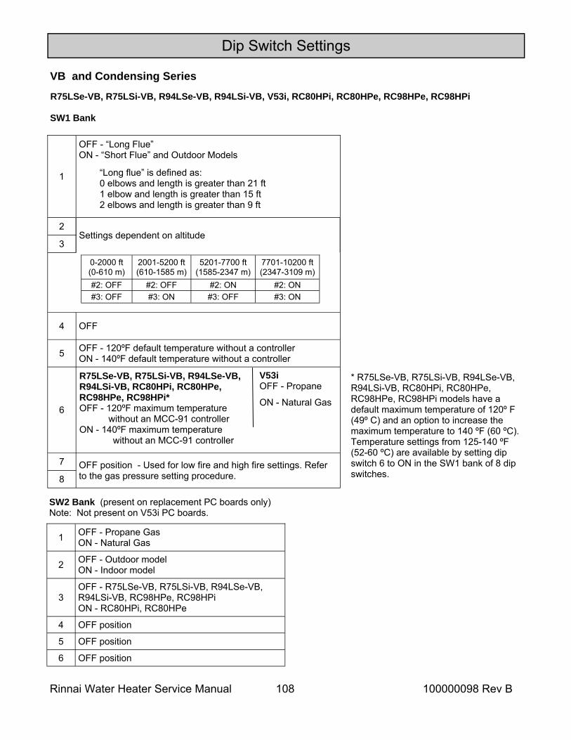
Rinnai Water Heater Service Manual 108 100000098 Rev B
Dip Switch Settings
0-2000 ft (0-610 m)
2001-5200 ft (610-1585 m)
5201-7700 ft (1585-2347 m)
7701-10200 ft (2347-3109 m)
#2: OFF #2: OFF #2: ON #2: ON #3: OFF #3: ON #3: OFF #3: ON
VB and Condensing Series
SW1 Bank
SW2 Bank (present on replacement PC boards only) Note: Not present on V53i PC boards.
1 OFF - Propane Gas ON - Natural Gas
2 OFF - Outdoor model ON - Indoor model
3 OFF - R75LSe-VB, R75LSi-VB, R94LSe-VB, R94LSi-VB, RC98HPe, RC98HPi ON - RC80HPi, RC80HPe
4 OFF position
5 OFF position
6 OFF position
1
OFF - “Long Flue” ON - “Short Flue” and Outdoor Models
2 Settings dependent on altitude
3
4 OFF
5 OFF - 120ºF default temperature without a controller ON - 140ºF default temperature without a controller
6
7 OFF position - Used for low fire and high fire settings. Refer to the gas pressure setting procedure. 8
“Long flue” is defined as: 0 elbows and length is greater than 21 ft 1 elbow and length is greater than 15 ft 2 elbows and length is greater than 9 ft
* R75LSe-VB, R75LSi-VB, R94LSe-VB, R94LSi-VB, RC80HPi, RC80HPe, RC98HPe, RC98HPi models have a default maximum temperature of 120º F (49º C) and an option to increase the maximum temperature to 140 ºF (60 ºC). Temperature settings from 125-140 ºF (52-60 ºC) are available by setting dip switch 6 to ON in the SW1 bank of 8 dip switches.
R75LSe-VB, R75LSi-VB, R94LSe-VB, R94LSi-VB, RC80HPi, RC80HPe, RC98HPe, RC98HPi* OFF - 120ºF maximum temperature
without an MCC-91 controller ON - 140ºF maximum temperature without an MCC-91 controller
V53i OFF - Propane
ON - Natural Gas
R75LSe-VB, R75LSi-VB, R94LSe-VB, R94LSi-VB, V53i, RC80HPi, RC80HPe, RC98HPe, RC98HPi
Rinnai Water Heater Service Manual 109 100000098 Rev B
Notes

Rinnai Water Heater Service Manual 110 100000098 Rev B
Notes
Rinnai Water Heater Service Manual 111 100000098 Rev B
Notes
© 2011 Rinnai America Corporation
100000098 Rev B
7/2011