Embed Size (px)
Citation preview

UNCLASSIFIED: Dist A. Approved for public release
TARDEC Hybrid Electric (HE) Technology Program
5 Feb 2011
Briefer: Gus Khalil
TARDEC GVPM
Hybrid Electric Team Leader
UNCLASSIFIED: Dist A. Approved for public release
Report Documentation Page Form ApprovedOMB No. 0704-0188
Public reporting burden for the collection of information is estimated to average 1 hour per response, including the time for reviewing instructions, searching existing data sources, gathering andmaintaining the data needed, and completing and reviewing the collection of information. Send comments regarding this burden estimate or any other aspect of this collection of information,including suggestions for reducing this burden, to Washington Headquarters Services, Directorate for Information Operations and Reports, 1215 Jefferson Davis Highway, Suite 1204, ArlingtonVA 22202-4302. Respondents should be aware that notwithstanding any other provision of law, no person shall be subject to a penalty for failing to comply with a collection of information if itdoes not display a currently valid OMB control number.
1. REPORT DATE 05 FEB 2011
2. REPORT TYPE N/A
3. DATES COVERED -
4. TITLE AND SUBTITLE TARDEC Hybrid Electric (HE) Technology Program
5a. CONTRACT NUMBER
5b. GRANT NUMBER
5c. PROGRAM ELEMENT NUMBER
6. AUTHOR(S) Gus Khalil
5d. PROJECT NUMBER
5e. TASK NUMBER
5f. WORK UNIT NUMBER
7. PERFORMING ORGANIZATION NAME(S) AND ADDRESS(ES) US Army RDECOM-TARDEC 6501 E 11 Mile Rd Warren, MI48397-5000, USA
8. PERFORMING ORGANIZATION REPORT NUMBER 21479RC
9. SPONSORING/MONITORING AGENCY NAME(S) AND ADDRESS(ES) US Army RDECOM-TARDEC 6501 E 11 Mile Rd Warren, MI48397-5000, USA
10. SPONSOR/MONITOR’S ACRONYM(S) TACOM/TARDEC/RDECOM
11. SPONSOR/MONITOR’S REPORT NUMBER(S) 21479RC
12. DISTRIBUTION/AVAILABILITY STATEMENT Approved for public release, distribution unlimited
13. SUPPLEMENTARY NOTES The original document contains color images.
14. ABSTRACT
15. SUBJECT TERMS
16. SECURITY CLASSIFICATION OF: 17. LIMITATIONOF ABSTRACT
SAR
18.NUMBEROF PAGES
62
19a. NAME OF RESPONSIBLE PERSON
a. REPORT unclassified
b. ABSTRACT unclassified
c. THIS PAGE unclassified
Standard Form 298 (Rev. 8-98) Prescribed by ANSI Std Z39-18
UNCLASSIFIED: Dist A. Approved for public release
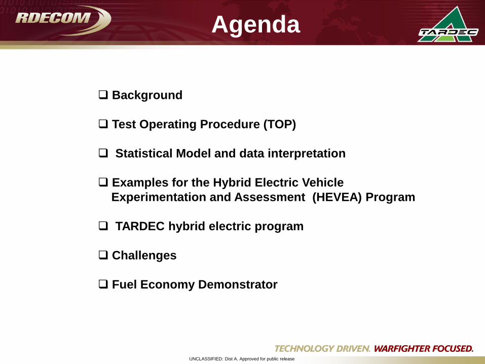
Agenda
Background
Test Operating Procedure (TOP)
Statistical Model and data interpretation
Examples for the Hybrid Electric Vehicle
Experimentation and Assessment (HEVEA) Program
TARDEC hybrid electric program
Challenges
Fuel Economy Demonstrator
UNCLASSIFIED: Dist A. Approved for public release
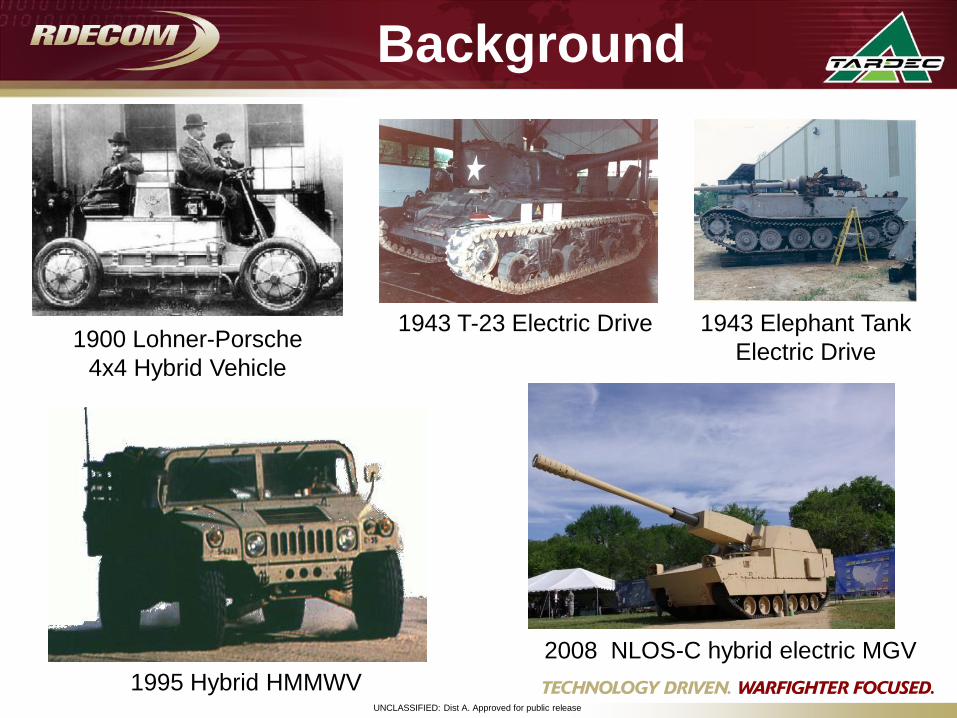
Background
1900 Lohner-Porsche
4x4 Hybrid Vehicle
1943 T-23 Electric Drive 1943 Elephant Tank
Electric Drive
2008 NLOS-C hybrid electric MGV
1995 Hybrid HMMWV
UNCLASSIFIED: Dist A. Approved for public release
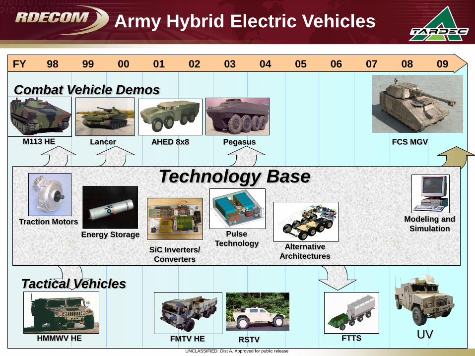
Tactical Vehicles
FMTV HEHMMWV HE
Combat Vehicle Demos
M113 HE PegasusAHED 8x8
Army Hybrid Electric Vehicles
FTTS
Technology Base
Traction Motors
Alternative
Architectures
Pulse
Technology
Modeling and
Simulation
FY 98 99 00 01 02 03 04 05 06 07 08 09
UV RSTV
Lancer
Energy Storage
SiC Inverters/
Converters
FCS MGV
UNCLASSIFIED: Dist A. Approved for public release
Test Operating Procedure (TOP)
UNCLASSIFIED: Dist A. Approved for public release
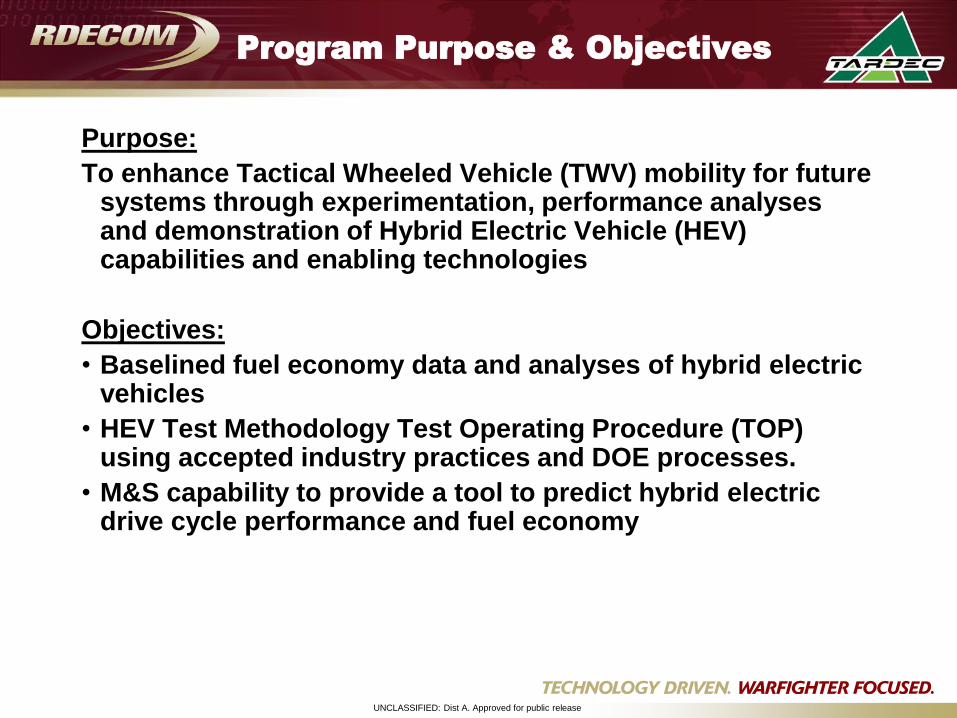
Program Purpose & Objectives
Purpose:
To enhance Tactical Wheeled Vehicle (TWV) mobility for future systems through experimentation, performance analyses and demonstration of Hybrid Electric Vehicle (HEV) capabilities and enabling technologies
Objectives:
• Baselined fuel economy data and analyses of hybrid electric vehicles
• HEV Test Methodology Test Operating Procedure (TOP) using accepted industry practices and DOE processes.
• M&S capability to provide a tool to predict hybrid electric drive cycle performance and fuel economy
UNCLASSIFIED: Dist A. Approved for public release
HEVEA Fuel Consumption
Test Methodology
• The Top defines fuel economy over a spectrum of military
terrains and speeds
• Consensus and acceptance of test methodology are
sought from government, industry, and academia
• Test data are being used to validate the VPSET models
UNCLASSIFIED: Dist A. Approved for public release
HEVEA Test Methodology for Evaluating Fuel Economy
• Vehicle Preparation and Preliminary check out Tests
• Definition of Terrains & Test Courses
• Establishment of Hybrid Control Strategy Characteristics
• Test Conduct and methods of measurements
• Expression of Fuel Economy Calculations (Example)
• Development and Revision Process Overview
Test Methodology
and TOP Overview
UNCLASSIFIED: Dist A. Approved for public release
Test Vehicle Preparation
• Each vehicle is initially tested to characterize and define its basic automotive
performance capabilities.
• The tests and parameters to be determined are:
– Weight distribution
– Center of gravity
– Coast down from maximum road speed
– Acceleration to maximum road speed
– Rolling resistance, resistance to tow
– The Electrical Energy Storage System (EESS) capacity
– Estimation of frontal area
UNCLASSIFIED: Dist A. Approved for public release
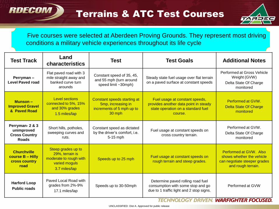
Terrains & ATC Test Courses
Test TrackLand
characteristicsTest Test Goals Additional Notes
Perryman –
Level Paved road
Flat paved road with 3
mile straight away and
banked curve turn
arounds
Constant speed of 35, 45,
and 55 mph (turn around
speed limit ~30mph)
Steady state fuel usage over flat terrain
on a paved surface at constant speeds
Performed at Gross Vehicle
Weight (GVW)
Delta State Of Charge
monitored
Munson –
Improved Gravel
& Paved Road
Level sections
connected to 5%, 15%
and 30% grades
1.5 miles/lap
Constant speeds starting at
5mp, increasing in
increments of 5 mph up to
30 mph
Fuel usage at constant speeds,
provides another data point in steady
state operation on a standard fuel
course.
Performed at GVW.
Delta State Of Charge
monitored
Perryman- 2 & 3
unimproved
Cross Country
Roads
Short hills, potholes,
sweeping curves and
ruts.
Constant speed as dictated
by the driver’s comfort, i.e.
5-15 mph
Fuel usage at constant speeds on
cross country terrain.
Performed at GVW.
Delta State Of Charge
monitored
Churchville
course B – Hilly
cross country
road
Steep grades up to
29%, terrain is
moderate to rough with
varied moguls
3.7 miles/lap
Speeds up to 25 mphFuel usage at constant speeds on
rough terrain and steep grades.
Performed at GVW. Also
shows whether the vehicle
can negotiate steeper grades
and rough terrain.
Harford Loop
Public roads
Paved Local Road with
grades from 2%-9%
17.1 miles/lap
Speeds up to 30-50mph
Determine paved rolling road fuel
consumption with some stop and go
due to 1 traffic light and 2 stop signs.
Performed at GVW
Five courses were selected at Aberdeen Proving Grounds. They represent most driving
conditions a military vehicle experiences throughout its life cycle
UNCLASSIFIED: Dist A. Approved for public release
Establish Hybrid Control Strategy
Characteristics
• Manufacturer determines selectable modes of operation
• Determination of initial high and low SOC for the traction battery
• Characterization of energy storage modes for each terrain
– Charge Sustaining
– Charge Depleting
– Charge Increasing
• Control strategy – specifics may not be known, but the results are apparent
and expressed through test data and observation
– Road Speed
– Fuel Consumed
– Test Time
– Change in traction battery energy stored or depleted
– Other measured parameters
UNCLASSIFIED: Dist A. Approved for public release
Test Conduct
• Conduct steady state speed test runs at 5 mph increments encompassing
entire speed operating range of the vehicle for each terrain
• Factors defining operable speed range will include:
– Vehicle dynamic stability
– Ride quality for operator safety
– Ride quality to prevent damage to test vehicle
• Test Data:
– Engine Fuel Economy (mpg)
– Delta State of Charge (SOC)
– Average Road Speed (mph)
UNCLASSIFIED: Dist A. Approved for public release
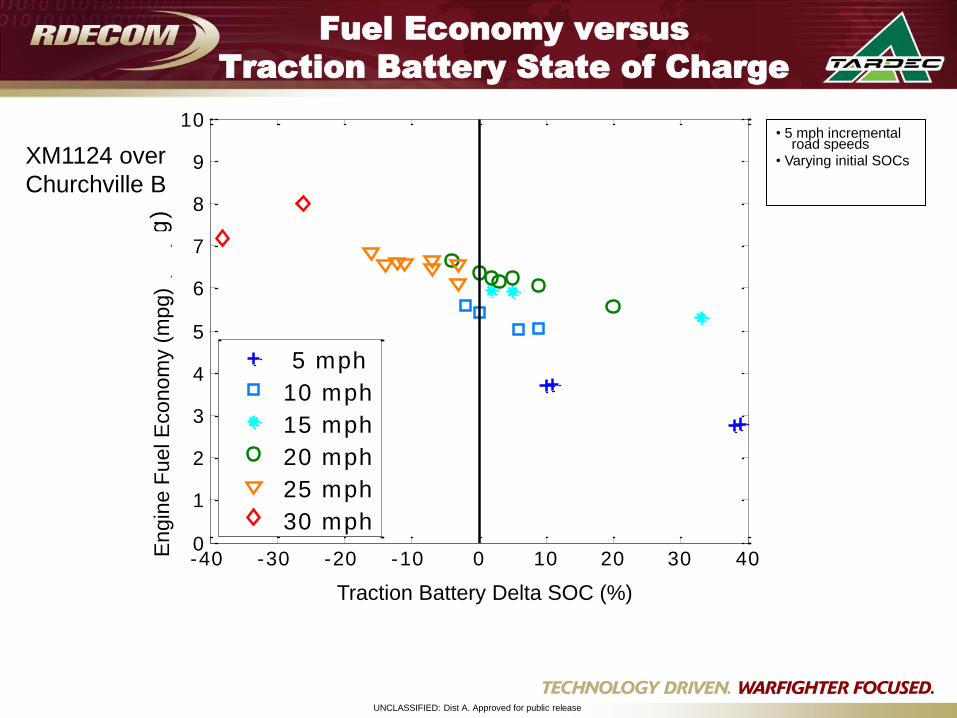
Fuel Economy versus
Traction Battery State of Charge
-40 -30 -20 -10 0 10 20 30 400
1
2
3
4
5
6
7
8
9
10
Delta SOC (%)
Fuel Econom
y (
mpg)
5 mph
10 mph
15 mph
20 mph
25 mph
30 mph
• 5 mph incremental road speeds
• Varying initial SOCsE
ngin
e F
uel E
conom
y (
mpg)
Traction Battery Delta SOC (%)
XM1124 over
Churchville B
UNCLASSIFIED: Dist A. Approved for public release
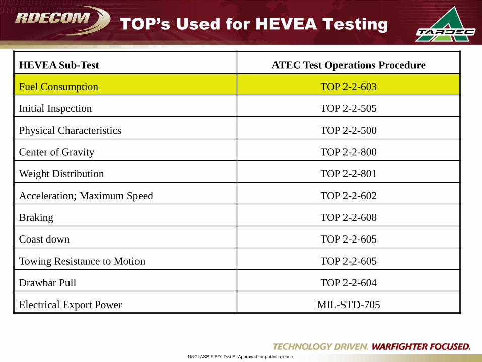
TOP’s Used for HEVEA Testing
HEVEA Sub-Test ATEC Test Operations Procedure
Fuel Consumption TOP 2-2-603
Initial Inspection TOP 2-2-505
Physical Characteristics TOP 2-2-500
Center of Gravity TOP 2-2-800
Weight Distribution TOP 2-2-801
Acceleration; Maximum Speed TOP 2-2-602
Braking TOP 2-2-608
Coast down TOP 2-2-605
Towing Resistance to Motion TOP 2-2-605
Drawbar Pull TOP 2-2-604
Electrical Export Power MIL-STD-705
UNCLASSIFIED: Dist A. Approved for public release
Statistical Modeling
Statistical Modeling Overview
UNCLASSIFIED: Dist A. Approved for public release
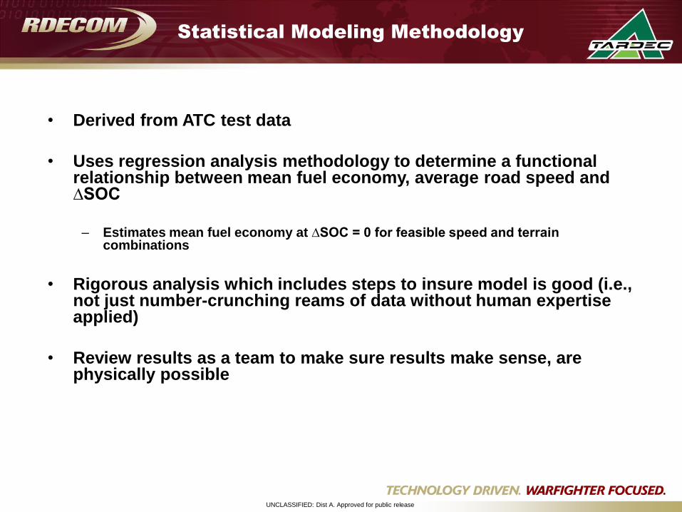
Statistical Modeling Methodology
• Derived from ATC test data
• Uses regression analysis methodology to determine a functional relationship between mean fuel economy, average road speed and ∆SOC
– Estimates mean fuel economy at ∆SOC = 0 for feasible speed and terrain combinations
• Rigorous analysis which includes steps to insure model is good (i.e., not just number-crunching reams of data without human expertise applied)
• Review results as a team to make sure results make sense, are physically possible
UNCLASSIFIED: Dist A. Approved for public release
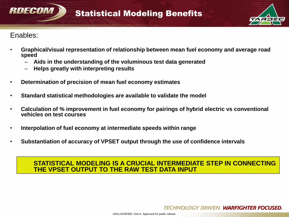
Enables:
• Graphical/visual representation of relationship between mean fuel economy and average road speed
– Aids in the understanding of the voluminous test data generated
– Helps greatly with interpreting results
• Determination of precision of mean fuel economy estimates
• Standard statistical methodologies are available to validate the model
• Calculation of % improvement in fuel economy for pairings of hybrid electric vs conventional vehicles on test courses
• Interpolation of fuel economy at intermediate speeds within range
• Substantiation of accuracy of VPSET output through the use of confidence intervals
STATISTICAL MODELING IS A CRUCIAL INTERMEDIATE STEP IN CONNECTING THE VPSET OUTPUT TO THE RAW TEST DATA INPUT
Statistical Modeling Benefits
UNCLASSIFIED: Dist A. Approved for public release
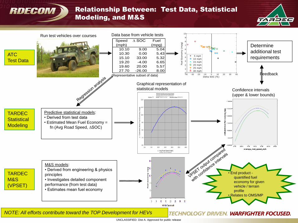
Relationship Between: Test Data, Statistical
Modeling, and M&S
Determine
additional test
requirements
TARDEC
Statistical
Modeling
TARDEC
M&S
(VPSET)
ATC
Test Data
Run test vehicles over coursesSpeed ∆ SOC Fuel
(mph) (mpg)
10.10 9.00 5.04
10.30 0.00 5.43
15.10 33.00 5.32
19.20 -4.00 6.65
19.60 20.00 5.57
27.70 -26.00 8.00
Data base from vehicle tests
Graphical representation of
statistical models Confidence intervals
(upper & lower bounds) HEVEA Fuel Economy Experiment
Test Course: Munson Test Area, Std Fuel Course
Fuel Type: JP-8 Test Site: Aberdeen Test Center Delta State of Charge (XM1124): 0%
6.0
7.0
8.0
9.0
10.0
11.0
12.0
0.0 5.0 10.0 15.0 20.0 25.0 30.0
x: Avg Road Speed (mph)Test Dates: Sep, Nov 06 (Munson)
y:
Estim
ate
d M
ea
n F
ue
l E
co
nom
y (
mp
g)
Feedback
Predictive statistical models:
• Derived from test data
• Estimated Mean Fuel Economy =
fn (Avg Road Speed, ∆SOC)
-40 -30 -20 -10 0 10 20 30 400
1
2
3
4
5
6
7
8
9
10
Delta SOC (%)
Fuel Econom
y (
mpg)
5 mph
10 mph
15 mph
20 mph
25 mph
30 mph
M&S models:
• Derived from engineering & physics
principles
• Investigates detailed component
performance (from test data)
• Estimates mean fuel economy
NOTE: All efforts contribute toward the TOP Development for HEVs
(Representative subset of data)
• End product -
quantified fuel
economy for given
vehicle / terrain
profile
• Relates to OMS/MP
UNCLASSIFIED: Dist A. Approved for public release
Examples from the HEVEA test data
UNCLASSIFIED: Dist A. Approved for public release
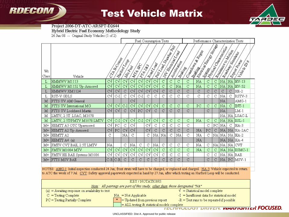
Test Vehicle Matrix
UNCLASSIFIED: Dist A. Approved for public release
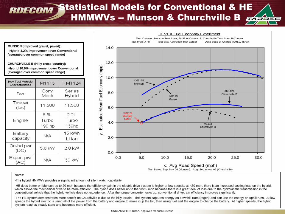
Statistical Models for Conventional & HE
HMMWVs -- Munson & Churchville B
HEVEA Fuel Economy Experiment
Test Courses: Munson Test Area, Std Fuel Course & Churchville Test Area, B-Course
Fuel Type: JP-8 Test Site: Aberdeen Test Center Delta State of Charge (XM1124): 0%
0.0
2.0
4.0
6.0
8.0
10.0
12.0
14.0
0.0 5.0 10.0 15.0 20.0 25.0 30.0
x: Avg Road Speed (mph)Test Dates: Sep, Nov 06 (Munson); Aug, Sep & Nov 06 (Churchville)
y: E
stim
ate
d M
ean
Fue
l Eco
nom
y (m
pg)
XM1124
Munson
M1113
Munson
M1113
Churchville B
XM1124
Churchville B
XM1124
charging
battery
Notes:
-The hybrid HMMWV provides a significant amount of silent watch capability
-HE does better on Munson up to 20 mph because the efficiency gain in the electric drive system is higher at low speeds; at >20 mph, there is an increased cooling load on the hybrid, which allows the mechanical drive to be more efficient. The hybrid does better up to the first 5 mph because there is a great deal of loss due to the hydrokinetic transmission in the conventional vehicle that the hybrid vehicle does not experience. After the torque converter locks up, conventional drivetrain efficiency improves significantly.
-The HE system demonstrates more benefit on Churchville B due to the hilly terrain. The system captures energy on downhill runs (regen) and can use the energy on uphill runs. At low speeds the hybrid electric is using all of the power from the battery and engine to make it up the hill, then using fuel and the engine to charge the battery. At higher speeds, the hybrid system reaches steady state and becomes more efficient.
MUNSON (Improved gravel, paved):
- Hybrid 4.2% improvement over Conventional
(averaged over common speed range)
CHURCHVILLE B (Hilly cross-country):
-Hybrid 10.9% improvement over Conventional
(averaged over common speed range)
UNCLASSIFIED: Dist A. Approved for public release
HMMWV Series HE
22
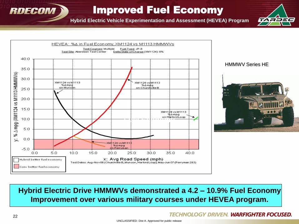
Hybrid Electric Drive HMMWVs demonstrated a 4.2 – 10.9% Fuel Economy
Improvement over various military courses under HEVEA program.
Improved Fuel Economy
Fuel Economy
Hybrid Electric Vehicle Experimentation and Assessment (HEVEA) Program
UNCLASSIFIED: Dist A. Approved for public release
TARDEC Hybrid Electric Program
UNCLASSIFIED: Dist A. Approved for public release
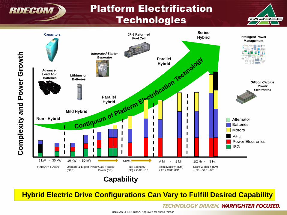
Platform Electrification
Technologies
Capability
Co
mp
lexit
y a
nd
Po
wer
Gro
wth
Onboard Power Fuel Economy
(FE) + O&E +BP
O&E + Boost
Power (BP)
Onboard & Export Power
(O&E)
Silent Mobility (SM)
+ FE+ O&E +BP
Silent Watch + (SM)
+ FE+ O&E +BP
5 kW - 30 kW 10 kW - 50 kW MPG ¼ Mi - 1 Mi 1/2 Hr - 8 Hr
Non - Hybrid
Mild Hybrid
Parallel
Hybrid
Alternator
Batteries
Motors
APU
Power Electronics
ISG
Integrated Starter
Generator
Silicon Carbide
Power
Electronics
JP-8 Reformed
Fuel Cell
Advanced
Lead Acid
BatteriesLithium Ion
Batteries
ESS
Elec
28V
Sta
rte
r ESS
Hull
28V
PCM3
0.8kW
PCM2
1.5kW
PCM1
1.5kW
Slip Ring
BMS2
ESS
Turret
28V
Smart
Display
(VPMS)
Dirty
Hull
Loads
Elect.
Loads
Turret
Loads
LV
610VDC
28VDC
NPS
HV/LV
LVPDB
2.24kW
HVPDB
DVDB
1.7-8.2kW
Hull
Loads
TPB
1.2-4.4kW
Gun/Turret
Drive Control
Turret
AOPET Test Control Panel
CleanHPB1
TP
EA
MP = Master Power switch
TP = Turret Power switch
EA = Engine Accy switch
oldnew
MP
AV900_CH1 (160kW)
Spare1 (30kW)
Spare2 (30kW)
AHU1
(1.4kW)
Control Line
BMS1
ECS_Compressor
(7.8kW)
ECS_Condensor_Fan
(4.4kW)
PECS_Pump
(1.7kW)
Rad_Fan1 (35kW)
AHU2
(1.4kW)Thermal
Mngmt
(VTMS)
3Ø VAC
G
D
L
S
B
A
E
M
C
5
M
C
4
HV/LV
Rad_Fan2 (35kW)
HV Enable
MC3
MC2
MC1
HPB2
HP
B3
200
80
80
80
80
80
80
80
80
500kbps
Ground Fault Detect
250kbps
PECS Loop
DCDC1
(10kW)
DCDC2
(10kW)
Coolant
Temp
Fuel
LevelEngine Accy
Master Power
Open/28V Inputs
Test Loads (Water Tank)
T
L
2
5
T
L
2
5
T
L
5
0
T
L
5
0
T
L
5
0
HEATER
18kW
700V
Engine
Status
Battle
Override
Load
Controls
Trans.
Status
Tactical
Idle
Fault
Induce
POL1
(DDC)
POL2
(DDC)
POL3
(Global ET)
AV900_CH2
(0-18kW)
DFMC
5
200
200
80
5
E-STOPNPS
Status
Load A
Gages
Bus V
Gages
Fuel
Pump
Open/Ground Outputs
Eng Clnt
Temp
Level
SwitchEngine Oil
Pressure
Trans Oil
Temp
CAN: Power
CAN: Thermal
500kbps
T
L
2
5
1000
1000
Intelligent Power
Management
Capacitors
Hybrid Electric Drive Configurations Can Vary to Fulfill Desired Capability
Parallel
Hybrid
Series
Hybrid
UNCLASSIFIED: Dist A. Approved for public release
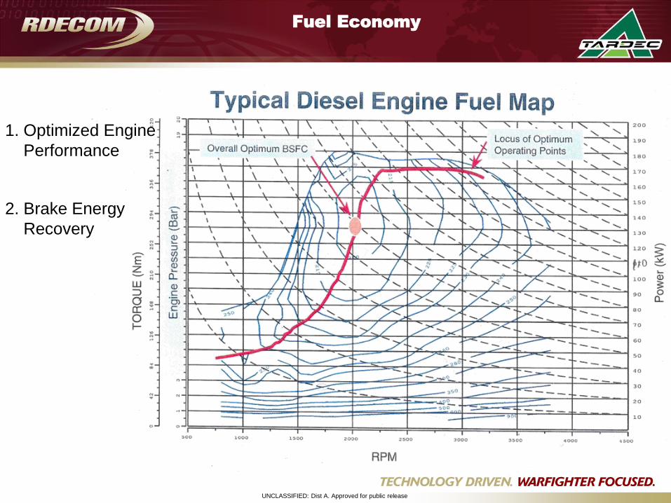
Fuel Economy
Optimized Engine
Performance
1.
Brake Energy
Recovery
2.
UNCLASSIFIED: Dist A. Approved for public release
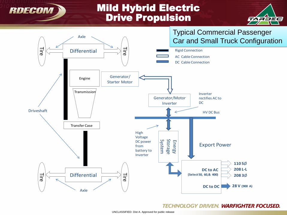
Tire
TireTire
TireDifferential
Differential
Energy
Storage
System
Generator/Motor
Inverter
Inverter rectifies AC to DC
High Voltage DC power from battery to Inverter
Engine Generator/
Starter Motor
Transmission
Transfer Case
Driveshaft
Axle
AxleFour Wheel Mild Hybrid Configuration
DC to AC(Select 50, 60,& 400)
110 SØ
208 L-L
208 3Ø
DC to DC 28 V (900 A)
Export Power
HV DC Bus
Rigid Connection
AC Cable Connection
DC Cable Connection
Mild Hybrid Electric
Drive Propulsion
Typical Commercial Passenger
Car and Small Truck Configuration
UNCLASSIFIED: Dist A. Approved for public release
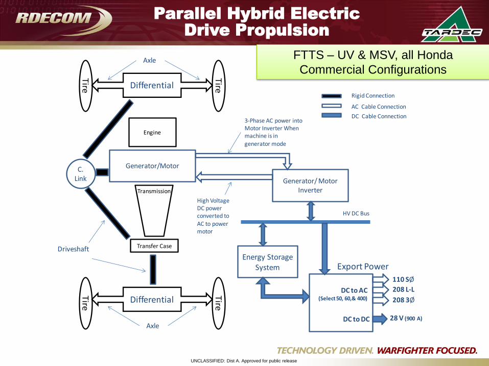
Parallel Hybrid Electric
Drive Propulsion
Tire
Tire
Tire
TireDifferential
Differential
Energy Storage System
Generator/ Motor Inverter
Engine
Generator/Motor
Transmission
3-Phase AC power into Motor Inverter When machine is in generator mode
C. Link
Transfer CaseDriveshaft
Axle
Axle
High Voltage DC power converted to AC to power motor
Four Wheel Drive Parallel Hybrid Configuration
DC to AC(Select 50, 60,& 400)
110 SØ
208 L-L
208 3Ø
DC to DC 28 V (900 A)
Export Power
HV DC Bus
Rigid Connection
AC Cable Connection
DC Cable Connection
FTTS – UV & MSV, all Honda
Commercial Configurations
UNCLASSIFIED: Dist A. Approved for public release
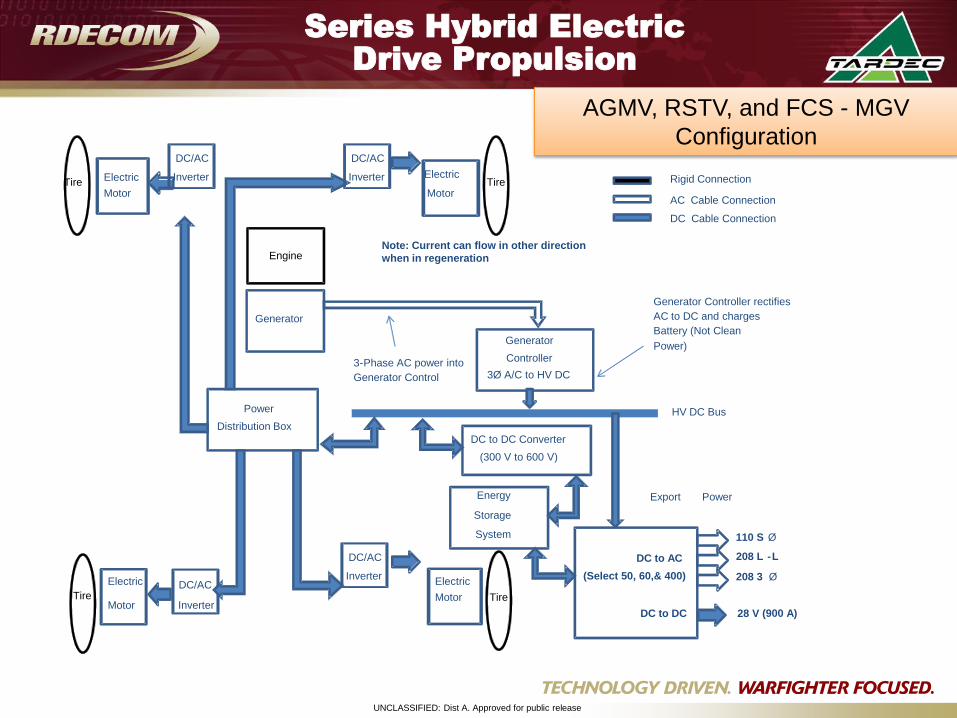
Series Hybrid Electric
Drive Propulsion
TireTire
Tire
Energy
Storage
System
Generator
Controller
3Ø A/C to HV DC
Generator Controller rectifies
AC to DC and charges
Battery (Not Clean
Power)
Engine
Generator
3-Phase AC power into
Generator Control
Series Hybrid Configuration
Power
Distribution Box
Electric
Motor Inverter
DC/AC Electric
Motor
DC to DC Converter
(300 V to 600 V)
Note: Current can flow in other direction
when in regeneration
DC to AC
(Select 50, 60,& 400)
110 S Ø
208 L -L
208 3 Ø
DC to DC 28 V (900 A)
Export Power
HV DC Bus
Rigid Connection
AC Cable Connection
DC Cable Connection
Tire Electric
Motor
Electric
Motor
DC/AC
Inverter
DC/AC
Inverter
DC/AC
Inverter
AGMV, RSTV, and FCS - MGV
Configuration
UNCLASSIFIED: Dist A. Approved for public release
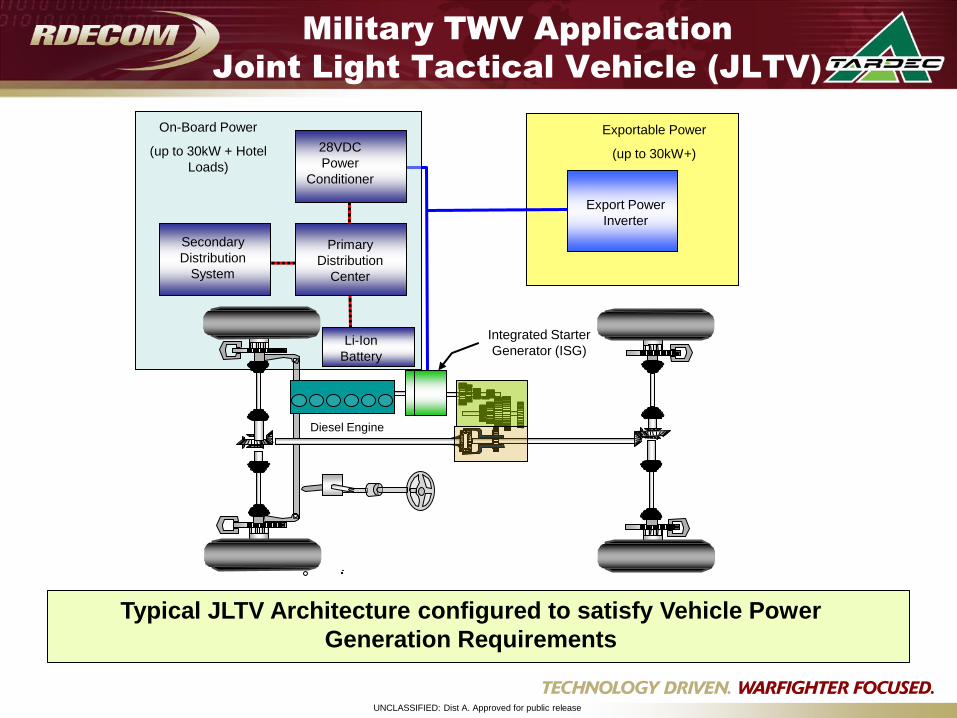
Military TWV Application
Joint Light Tactical Vehicle (JLTV)
Typical JLTV Architecture configured to satisfy Vehicle Power
Generation Requirements
Diesel Engine
Locking
Diff
Locking
Diff
Export Power
Inverter
28VDC
Power
Conditioner
Secondary
Distribution
System
Integrated Starter
Generator (ISG)
On-Board Power
(up to 30kW + Hotel
Loads)
Exportable Power
(up to 30kW+)
Li-Ion
Battery
Primary
Distribution
Center
UNCLASSIFIED: Dist A. Approved for public release
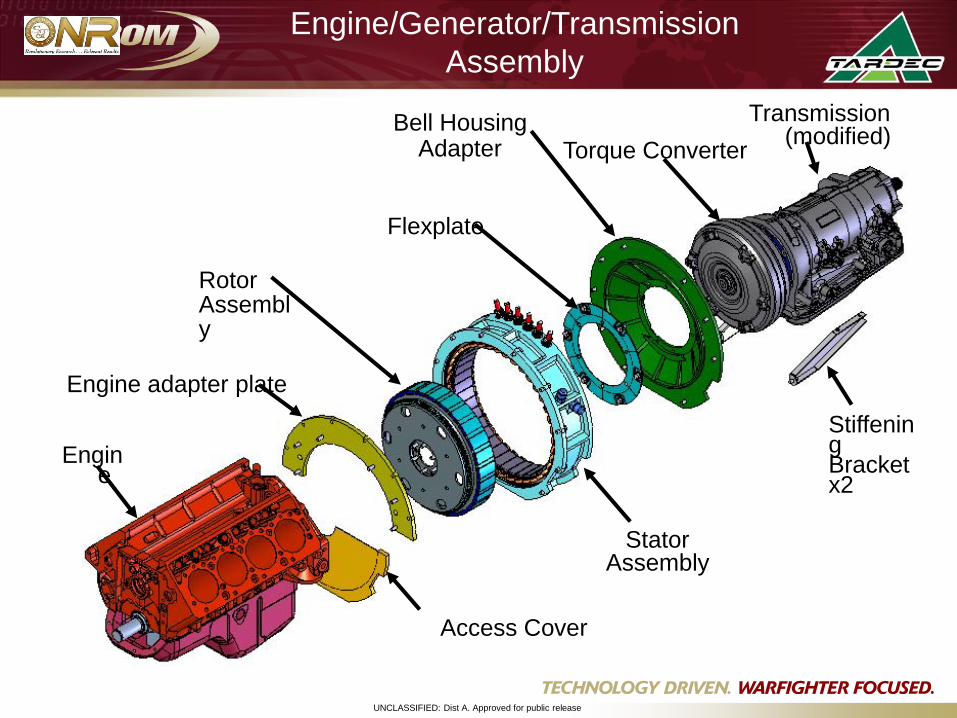
Engine/Generator/Transmission
Assembly
Access Cover
Engine adapter plate
Rotor Assembly
Bell HousingAdapter Torque Converter
Transmission (modified)
Engine
Flexplate
Stator Assembly
Stiffening Bracket x2

UNCLASSIFIED: Dist A. Approved for public release
Challenges
UNCLASSIFIED: Dist A. Approved for public release
Technical challenges
Power electronics operating temperature and space claim
Integration issues related to thermal management
Unproven reliability
Cost
Energy Storage limited energy density
Safety
High voltage control and management
UNCLASSIFIED: Dist A. Approved for public release
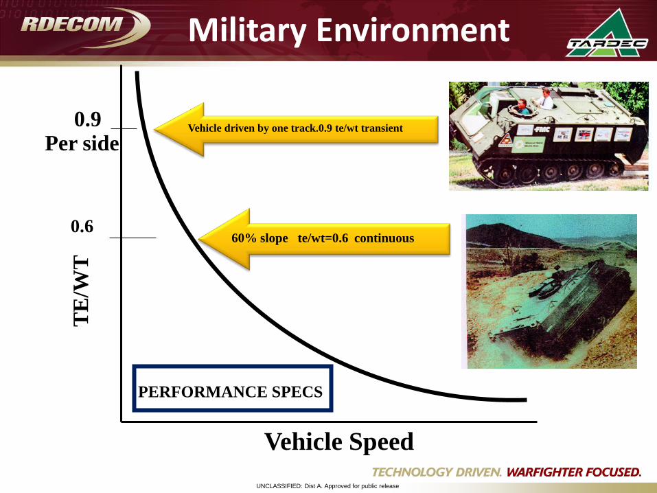
Vehicle Speed
TE
/WT
0.6
0.9Per side
Vehicle driven by one track.0.9 te/wt transient
PERFORMANCE SPECS
60% slope te/wt=0.6 continuous
Military Environment
UNCLASSIFIED: Dist A. Approved for public release
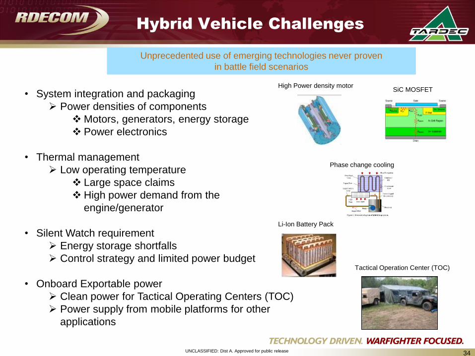
Hybrid Vehicle Challenges
34
• System integration and packaging
Power densities of components
Motors, generators, energy storage
Power electronics
• Thermal management
Low operating temperature
Large space claims
High power demand from the
engine/generator
• Silent Watch requirement
Energy storage shortfalls
Control strategy and limited power budget
• Onboard Exportable power
Clean power for Tactical Operating Centers (TOC)
Power supply from mobile platforms for other
applications
SiC MOSFETHigh Power density motor
Phase change cooling
Li-Ion Battery Pack
Tactical Operation Center (TOC)
Unprecedented use of emerging technologies never proven
in battle field scenarios
UNCLASSIFIED: Dist A. Approved for public release
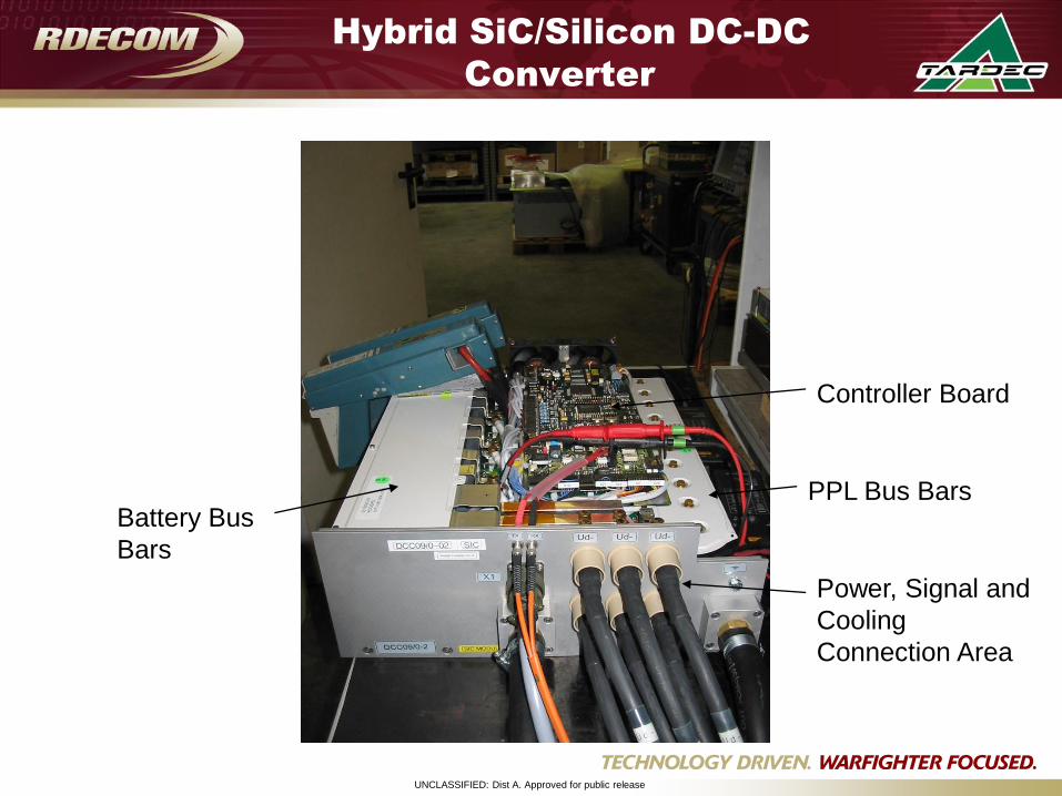
Hybrid SiC/Silicon DC-DC
Converter
Controller Board
PPL Bus BarsBattery Bus
Bars
Power, Signal and
Cooling
Connection Area
UNCLASSIFIED: Dist A. Approved for public release
Other High Temperature
Components
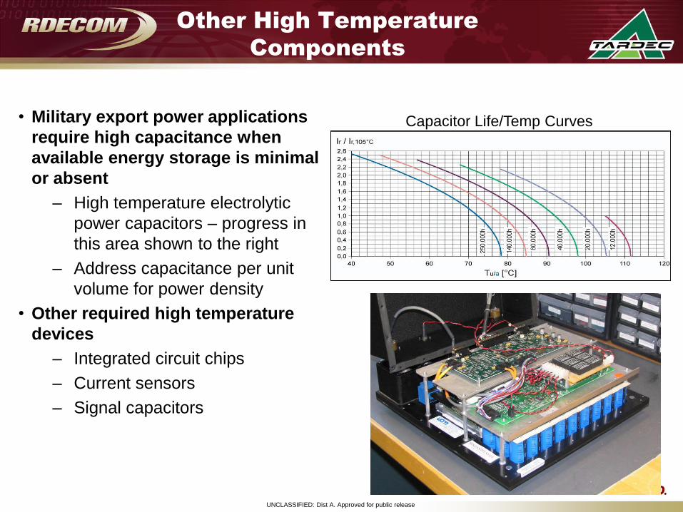
• Military export power applications
require high capacitance when
available energy storage is minimal
or absent
– High temperature electrolytic
power capacitors – progress in
this area shown to the right
– Address capacitance per unit
volume for power density
• Other required high temperature
devices
– Integrated circuit chips
– Current sensors
– Signal capacitors
Capacitor Life/Temp Curves
UNCLASSIFIED: Dist A. Approved for public release
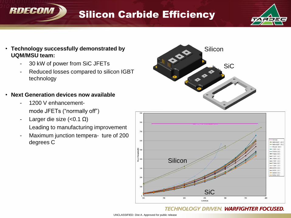
Silicon Carbide Efficiency
• Technology successfully demonstrated by
UQM/MSU team:
- 30 kW of power from SiC JFETs
- Reduced losses compared to silicon IGBT
technology
• Next Generation devices now available
- 1200 V enhancement-
mode JFETs (“normally off”)
- Larger die size (<0.1 Ω)
Leading to manufacturing improvement
- Maximum junction tempera- ture of 200
degrees C
Silicon
SiC
Silicon
SiC
UNCLASSIFIED: Dist A. Approved for public release
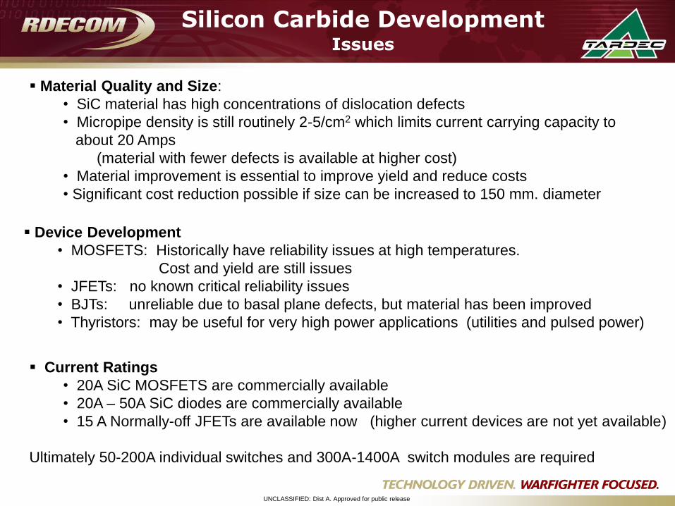
Material Quality and Size:
• SiC material has high concentrations of dislocation defects
• Micropipe density is still routinely 2-5/cm2 which limits current carrying capacity to
about 20 Amps
(material with fewer defects is available at higher cost)
• Material improvement is essential to improve yield and reduce costs
• Significant cost reduction possible if size can be increased to 150 mm. diameter
Device Development
• MOSFETS: Historically have reliability issues at high temperatures.
Cost and yield are still issues
• JFETs: no known critical reliability issues
• BJTs: unreliable due to basal plane defects, but material has been improved
• Thyristors: may be useful for very high power applications (utilities and pulsed power)
Current Ratings
• 20A SiC MOSFETS are commercially available
• 20A – 50A SiC diodes are commercially available
• 15 A Normally-off JFETs are available now (higher current devices are not yet available)
Ultimately 50-200A individual switches and 300A-1400A switch modules are required
Silicon Carbide DevelopmentIssues
UNCLASSIFIED: Dist A. Approved for public release
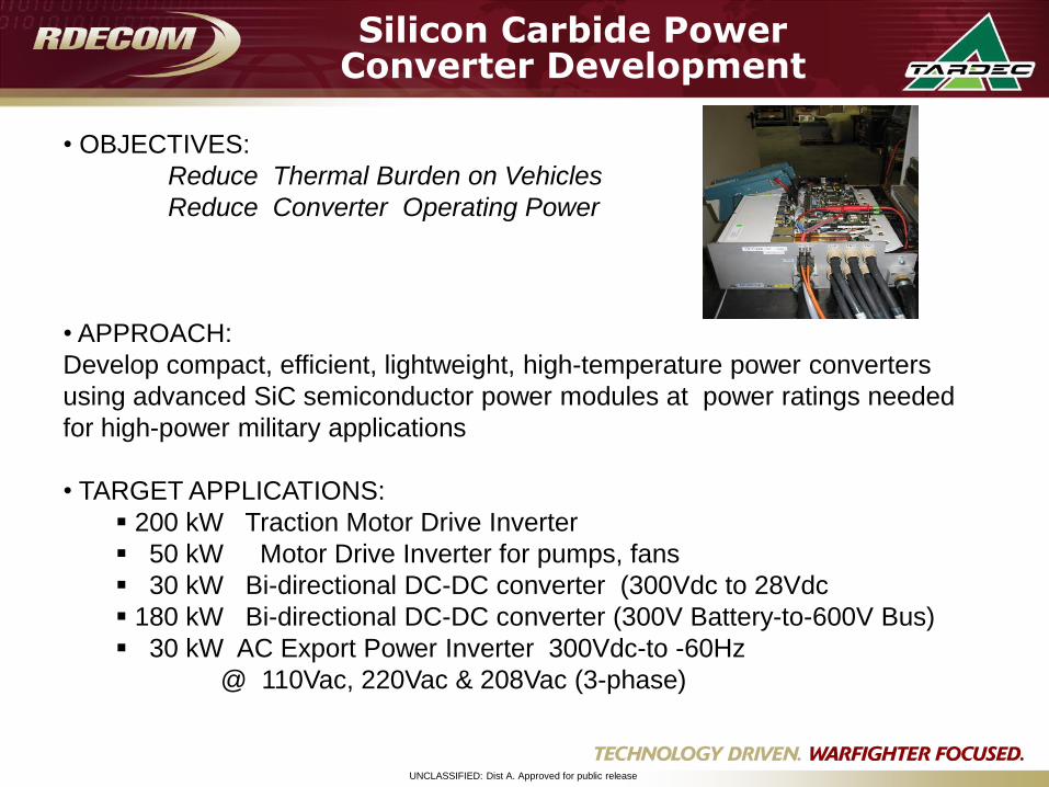
• OBJECTIVES:
Reduce Thermal Burden on Vehicles
Reduce Converter Operating Power
• APPROACH:
Develop compact, efficient, lightweight, high-temperature power converters
using advanced SiC semiconductor power modules at power ratings needed
for high-power military applications
• TARGET APPLICATIONS:
200 kW Traction Motor Drive Inverter
50 kW Motor Drive Inverter for pumps, fans
30 kW Bi-directional DC-DC converter (300Vdc to 28Vdc
180 kW Bi-directional DC-DC converter (300V Battery-to-600V Bus)
30 kW AC Export Power Inverter 300Vdc-to -60Hz
@ 110Vac, 220Vac & 208Vac (3-phase)
Silicon Carbide Power Converter Development
UNCLASSIFIED: Dist A. Approved for public release
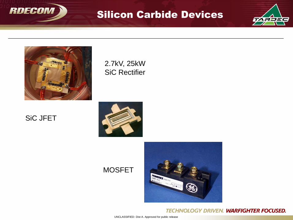
SiC JFET
2.7kV, 25kW
SiC Rectifier
MOSFET
Silicon Carbide Devices
UNCLASSIFIED: Dist A. Approved for public release
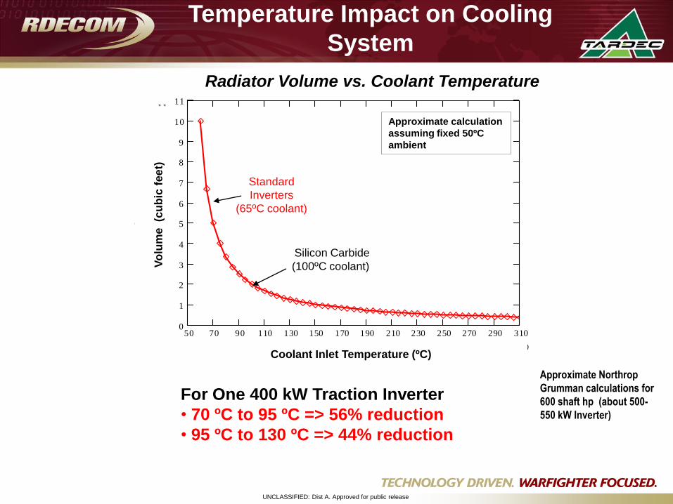
Temperature Impact on Cooling
System
Approximate Northrop
Grumman calculations for
600 shaft hp (about 500-
550 kW Inverter)
For One 400 kW Traction Inverter
• 70 ºC to 95 ºC => 56% reduction
• 95 ºC to 130 ºC => 44% reduction
50 70 90 110 130 150 170 190 210 230 250 270 290 3100
1
2
3
4
5
6
7
8
9
10
1111
0.385
vol T( )
31060 Tcool T( )
Radiator Volume vs. Coolant Temperature
Approximate calculation
assuming fixed 50ºC
ambient
Silicon Carbide
(100ºC coolant)
Standard
Inverters
(65ºC coolant)
Vo
lum
e (c
ub
ic f
ee
t)
Coolant Inlet Temperature (ºC)
UNCLASSIFIED: Dist A. Approved for public release
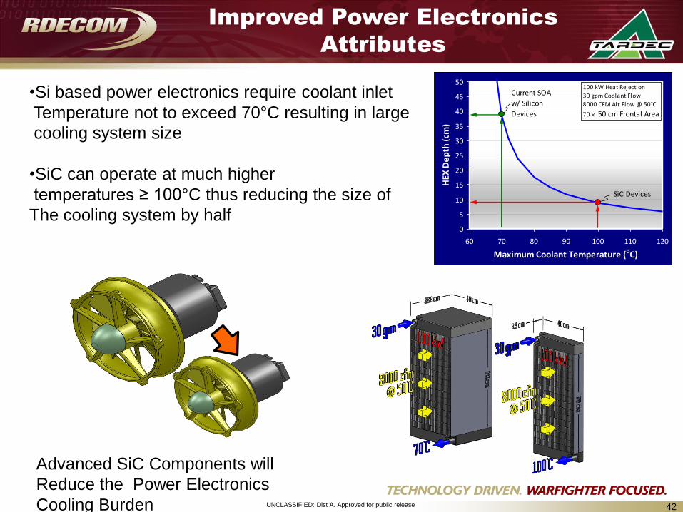
Improved Power Electronics
Attributes
0
5
10
15
20
25
30
35
40
45
50
60 70 80 90 100 110 120
Maximum Coolant Temperature (oC)
HEX
De
pth
(cm
)
100 kW Heat Rejection
30 gpm Coolant Flow
8000 CFM Air Flow @ 50°C
70 50 cm Frontal Area
Current SOA
w/ Silicon
Devices
SiC Devices
Advanced SiC Components will
Reduce the Power Electronics
Cooling Burden
•Si based power electronics require coolant inlet
Temperature not to exceed 70°C resulting in large
cooling system size
•SiC can operate at much higher
temperatures ≥ 100°C thus reducing the size of
The cooling system by half
42
UNCLASSIFIED: Dist A. Approved for public release
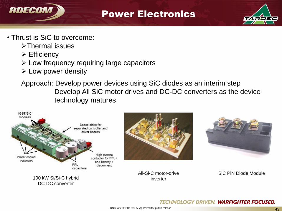
Power Electronics
43
100 kW Si/Si-C hybrid
DC-DC converter
All-Si-C motor-drive
inverter
SiC PiN Diode Module
• Thrust is SiC to overcome:
Thermal issues
Efficiency
Low frequency requiring large capacitors
Low power density
Approach: Develop power devices using SiC diodes as an interim step
Develop All SiC motor drives and DC-DC converters as the device
technology matures
UNCLASSIFIED: Dist A. Approved for public release
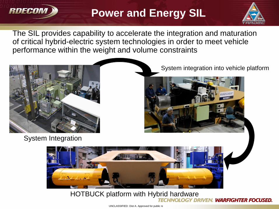
Power and Energy SIL
The SIL provides capability to accelerate the integration and maturation of critical hybrid-electric system technologies in order to meet vehicle performance within the weight and volume constraints
System Integration
System integration into vehicle platform
HOTBUCK platform with Hybrid hardware
UNCLASSIFIED: Dist A. Approved for public release
Fuel Economy Demonstrator (FED)
UNCLASSIFIED: Dist A. Approved for public release
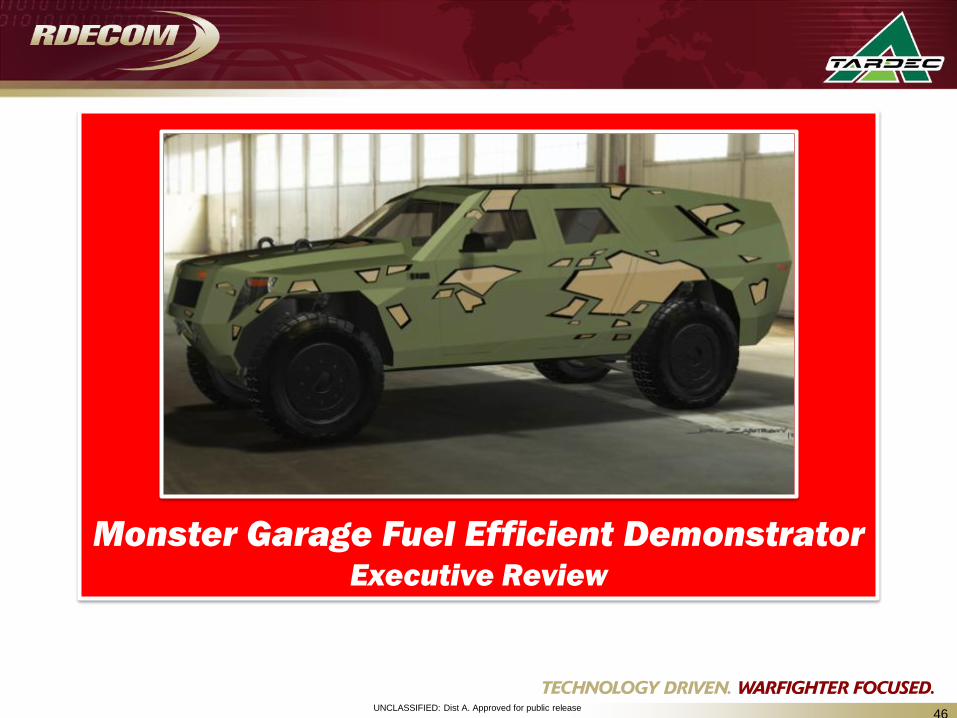
Monster Garage Fuel Efficient DemonstratorExecutive Review
46
UNCLASSIFIED: Dist A. Approved for public release47
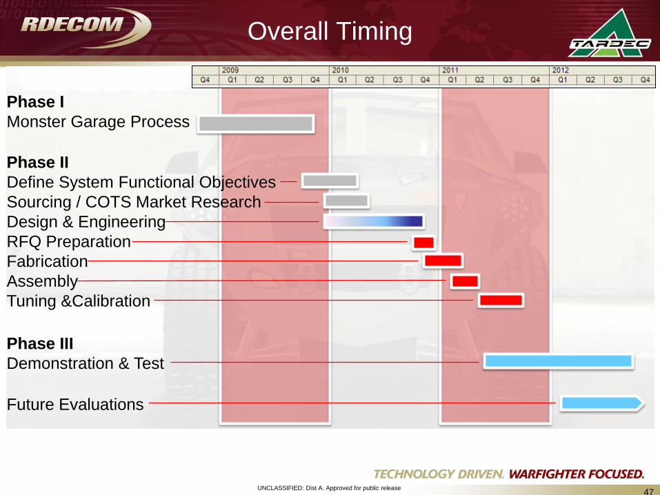
Overall Timing
Phase I
Monster Garage Process
Phase II
Define System Functional Objectives
Sourcing / COTS Market Research
Design & Engineering
RFQ Preparation
Fabrication
Assembly
Tuning &Calibration
Phase III
Demonstration & Test
Future Evaluations

UNCLASSIFIED: Dist A. Approved for public release
Final Exterior Design
48
8 Months from
Sketch to CAD
UNCLASSIFIED: Dist A. Approved for public release49
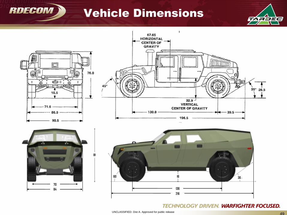
Vehicle Dimensions
136
216
84
70
16 3660
81
UNCLASSIFIED: Dist A. Approved for public release
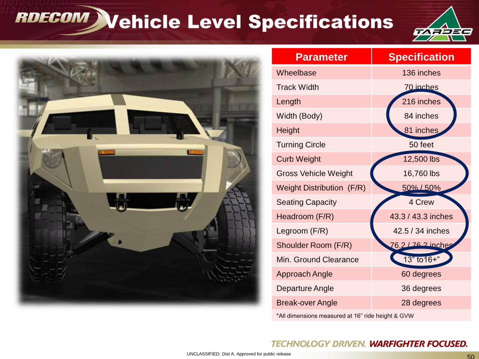
Vehicle Level Specifications
Parameter Specification
Wheelbase 136 inches
Track Width 70 inches
Length 216 inches
Width (Body) 84 inches
Height 81 inches
Turning Circle 50 feet
Curb Weight 12,500 lbs
Gross Vehicle Weight 16,760 lbs
Weight Distribution (F/R) 50% / 50%
Seating Capacity 4 Crew
Headroom (F/R) 43.3 / 43.3 inches
Legroom (F/R) 42.5 / 34 inches
Shoulder Room (F/R) 76.2 / 76.2 inches
Min. Ground Clearance 13” to16+”
Approach Angle 60 degrees
Departure Angle 36 degrees
Break-over Angle 28 degrees
*All dimensions measured at 16” ride height & GVW
50
UNCLASSIFIED: Dist A. Approved for public release
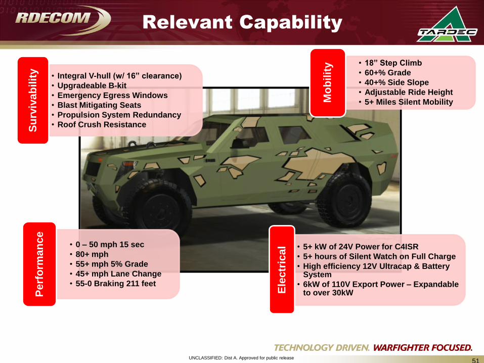
• 18” Step Climb
• 60+% Grade
• 40+% Side Slope
• Adjustable Ride Height
• 5+ Miles Silent MobilityMo
bilit
y
• 5+ kW of 24V Power for C4ISR
• 5+ hours of Silent Watch on Full Charge
• High efficiency 12V Ultracap & Battery System
• 6kW of 110V Export Power – Expandable to over 30kWE
lec
tric
al
51
Relevant Capability
• Integral V-hull (w/ 16” clearance)
• Upgradeable B-kit
• Emergency Egress Windows
• Blast Mitigating Seats
• Propulsion System Redundancy
• Roof Crush ResistanceSu
rviv
ab
ilit
y
• 0 – 50 mph 15 sec
• 80+ mph
• 55+ mph 5% Grade
• 45+ mph Lane Change
• 55-0 Braking 211 feet
Perf
orm
an
ce
UNCLASSIFIED: Dist A. Approved for public release52
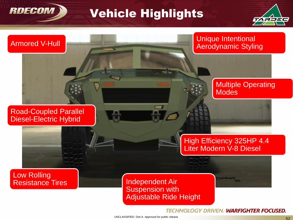
Vehicle Highlights
Unique Intentional Aerodynamic Styling
High Efficiency 325HP 4.4 Liter Modern V-8 Diesel
Road-Coupled Parallel Diesel-Electric Hybrid
Multiple Operating Modes
Low Rolling Resistance Tires Independent Air
Suspension with Adjustable Ride Height
Armored V-Hull
UNCLASSIFIED: Dist A. Approved for public release53
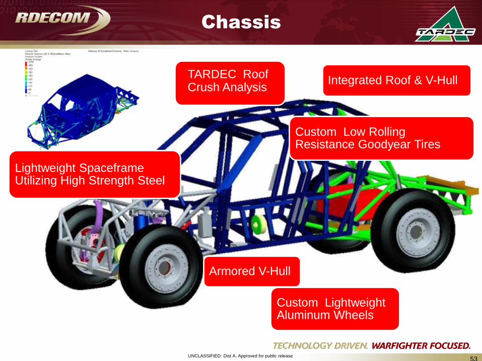
Chassis
Armored V-Hull
Custom Low Rolling Resistance Goodyear Tires
Custom Lightweight Aluminum Wheels
Integrated Roof & V-HullTARDEC Roof Crush Analysis
Lightweight SpaceframeUtilizing High Strength Steel
UNCLASSIFIED: Dist A. Approved for public release54
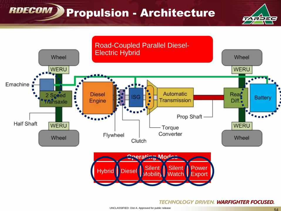
Propulsion - Architecture
Road-Coupled Parallel Diesel-Electric Hybrid
Operating Modes
Hybrid DieselSilent
MobilitySilent Watch
Power Export
UNCLASSIFIED: Dist A. Approved for public release55
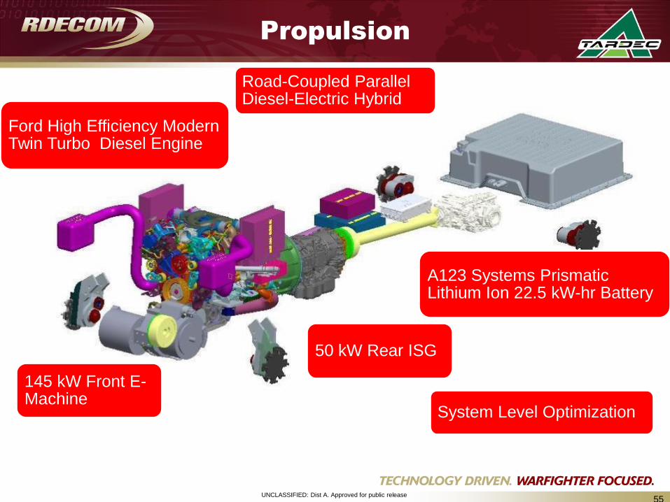
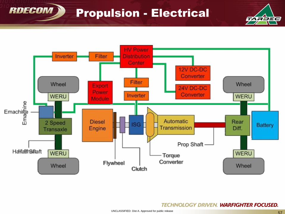
Propulsion
145 kW Front E-Machine
50 kW Rear ISG
A123 Systems Prismatic Lithium Ion 22.5 kW-hr Battery
Road-Coupled Parallel Diesel-Electric Hybrid
Ford High Efficiency Modern Twin Turbo Diesel Engine
System Level Optimization
UNCLASSIFIED: Dist A. Approved for public release56
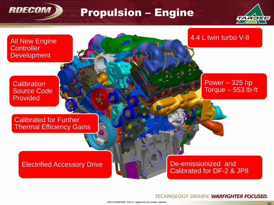
All New Engine Controller Development
Calibrated for Further Thermal Efficiency Gains
De-emissionized and Calibrated for DF-2 & JP8
Electrified Accessory Drive
Calibration Source Code Provided
4.4 L twin turbo V-8
Power – 325 hp Torque – 553 lb-ft
Propulsion – Engine
UNCLASSIFIED: Dist A. Approved for public release57
Propulsion - Electrical
UNCLASSIFIED: Dist A. Approved for public release58
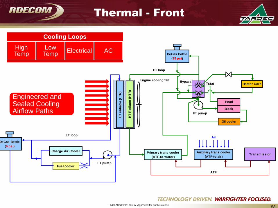
Thermal - Front
Engineered and Sealed Cooling Airflow Paths
LT
rad
iato
r (L
TR
)
Fuel cooler
Charge Air Cooler
LT pump
LT loop
DeGas Bottle
(6 psi)
Head
HT
Rad
iato
r (H
TR
)
HT pump
Engine cooling fan
Block
Oil cooler
HT loop
Heater Core
DeGas Bottle
(15 psi)
BypassTstat
Auxiliary trans cooler
(ATF-to-air)Transmission
Primary trans cooler
(ATF-to-water)
ATF
Air
Cooling Loops
High Temp
Low Temp
Electrical AC
UNCLASSIFIED: Dist A. Approved for public release59
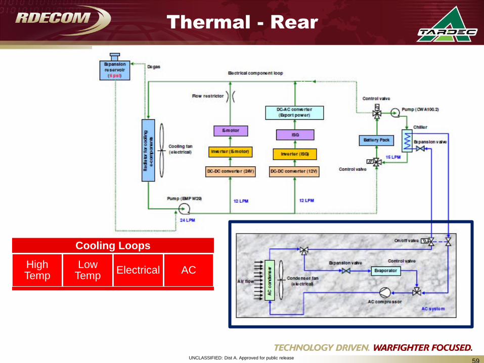
Thermal - Rear
Cooling Loops
High Temp
Low Temp
Electrical AC
UNCLASSIFIED: Dist A. Approved for public release60
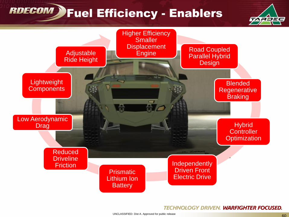
Fuel Efficiency - Enablers
Higher Efficiency Smaller
Displacement Engine
Road Coupled Parallel Hybrid
Design
Blended Regenerative
Braking
Hybrid Controller
Optimization
Independently Driven Front Electric Drive
Prismatic Lithium Ion
Battery
Reduced Driveline Friction
Low Aerodynamic Drag
Lightweight Components
Adjustable Ride Height
UNCLASSIFIED: Dist A. Approved for public release61
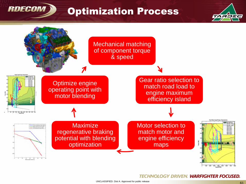
Optimization Process
Mechanical matching of component torque
& speed
Gear ratio selection to match road load to engine maximum efficiency island
Motor selection to match motor and engine efficiency
maps
Maximize regenerative braking
potential with blending optimization
Optimize engine operating point with
motor blending
UNCLASSIFIED: Dist A. Approved for public release62
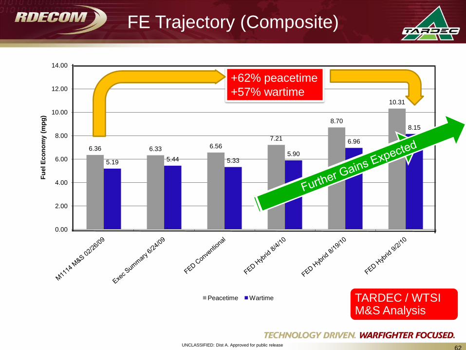
FE Trajectory (Composite)
6.36 6.33 6.56
7.21
8.70
10.31
5.19 5.44 5.335.90
6.96
8.15
0.00
2.00
4.00
6.00
8.00
10.00
12.00
14.00
Fu
el E
co
no
my (
mp
g)
Peacetime Wartime TARDEC / WTSI M&S Analysis
+62% peacetime
+57% wartime