Embed Size (px)
Citation preview
1
Task Based Groupware Design: Putting theory into practice
Gerrit van der Veer Division of Mathematics and Computer Science, FEW,
Vrije Universiteit, de Boelelaan 1081a 1081 HV Amsterdam, The Netherlands
+31 20 4447764 [email protected]
Martijn van Welie Division of Mathematics and Computer Science, FEW,
Vrije Universiteit, de Boelelaan 1081a 1081 HV Amsterdam, The Netherlands
+31 20 4447788 [email protected]
ABSTRACT Designing Groupware systems requires methods and tools that cover all aspects of Groupware systems. We present a method that utilizes known theoretical insights and makes them usable in practice. In our method, the design of Groupware systems is driven by an extensive task analysis followed by structured design and iterative evaluation using usability criteria. Using a combination of multiple complementary representations and techniques, a wide range of aspects of Groupware design is covered. The method is built on our experiences and is used in practice by several companies and educational institutes in Europe. We define the design process, the models needed and the tools that support the design process. Keywords DUTCH, Design Method, GTA, Groupware, Task Analysis, EUTERPE, Tools.
1. INTRODUCTION The design of Groupware is a complex activity. Methods for the design of such complex systems need to address many relevant aspects of a Groupware system including the users, their tasks and the software but also the physical and social environment of the system. Methods from HCI and CSCW literature individually address some of the relevant aspects but combining their insights in practice remains difficult. Moreover, the gap between theoretical ideas on design and applying them in practice is often large, rendering the theoretical ideas virtually useless. Based on our experiences in both industrial and educational projects, we developed a practical method for the design of Groupware. Despite the fact that we found that a theoretical foundation was necessary to solve certain problems in the design process, the method remained very practical. Our method, called DUTCH (Designing for Users and Tasks from Concepts to Handles), will be outlined in the next sections. The process, theory and representations will be discussed.
2. A TYPICAL EXAMPLE: One of our students has been working in a company that develops designs for a large international company in IT and electronics systems. The task domain we were involved in can be characterized as design of safety and security systems: systems intended to help protect access and safety in banks, systems that
are used to monitor industrial processes, systems that are applied for safeguarding railroad traffic. The systems are typical Groupware systems where the systems are embedded in complex organizations where people have different roles and responsibilities. The company has been providing these types of designs for over 10 years. Currently the company is frequently asked to redesign existing systems, as well as to design systems for new situations that resemble situations of systems that are already in use elsewhere. Traditionally the company used many different methods and techniques, each accommodating some aspects of the problem domain only. However, as many problems were repeatedly encountered, the company felt it needed a better design method. On a high level, the company wanted a method that adequately addressed all phases of design including: 1. Collecting insight in current situations, describing them and
analyzing them. The management of design projects was in most cases not even aware of the importance of this activity.
2. Considering the future situation in which a new design (or redesign) would be implemented, including the new system as well as the new work organization and procedures. Based on previous experiences, they felt this was necessary to do early and not after implementation of finished designs into full blown systems.
3. Relating detailed design of technology back to global analysis of the intended new work situation. Systematic evaluation can, when done in time, redirect the detail design before solutions are completely implemented.
4. Usability evaluation both early and late in a design cycle. There had always been evaluation procedures, but there has never been a clear view on what should be evaluated at which moment in the design cycle. Consequently, evaluation was driven by the availability of commercial tools and by the standards set by the clients of design who did not have a clear view on usability, even though they almost always had a view on safety and reliability (as far as hardware and software were concerned).
Since the company was working in design teams the company also had thoughts on the role of representations, besides being suitable for Groupware systems. Representations were needed for several different purposes such as: - for analyzing design knowledge, where frequently designers
had to collaborate with experts from different disciplines.
2
- for proposing and discussing global and detail solutions both internally and externally.
- for evaluation at different phases in the design process. - for transfer of decisions to implementation, which usually
meant handing over specifications to builders in a different company.
It was also important for the company that both the process and the techniques were supported by tools. The tools should support the designers in controlling the process, iteration and backtracking of decisions but also for producing solutions, proposals, to be elaborated by others, or to be analyzed, evaluated and tested. It was soon clear that there was not one "off the shelf" method that they could use. Most methods only cover some of the important aspects and often methods turn out to be difficult to use in practice.
3. CURRENT TASK BASED APPROCHES There are several methods that could be used to design Groupware. Table 1 shows some other task based methods and their characteristics. Most methods are targeted at several design activities but only a few address all activities. For use in industry this is problematic because a combination of methods needs to be chosen. Additionally, tool support only sparsely exists and most representations need to be created manually. In some industries, tool support is considered crucial. Also important is the availability of suitable representations that scale to real life design cases. Essential is the possibility to hierarchically structure diagrams and to highlight several different aspects of the problem domain or solution. Table 1 shows that none of the above methods excel in all categories. As our example illustrates, there is a need for a practical method that is addresses all the categories. Task based design approaches have demonstrated their potential but to advance into the daily practice of industry, several aspects still need to mature more. In Table 1, phases are indicated by the numbers used in the example of the previous section (1 = current work analysis, 2 = envisioning a new task world, 3 = detailed design, 4 = usability evaluation). Representation types indicate: H = hierarchy of concepts of a single type; F = (work/data/process)flow; S = semantic relations between different concept types; G = formal grammars.
4. A NEW APPROACH: DUTCH Since not one method covers all aspects well, we have developed our own approach, called DUTCH. Over the past years we have taken useful bits of theories and combined them into a coherent practical method for designing Groupware. The method has been used successfully in both industry and education proving the practical value of the method. From experiences such as outlined in the example, we learned that for a practical method it is required to a) define a clear process, b) define the models and representations including their semantics and c) support the method and models with tools. In the next sections we will define each of these requirements and we will show how we are dealing with those requirements. After this section discussed the general process, section 5 will discuss the process and representations for task modeling. Section 6 will discuss detailed design and section
7 discusses the evaluation process in detail. In section 8 tool support is discussed. Our design process is task based which means that it uses the tasks of users as a driving force in the design process. The goals are to design both usable and useful systems. We think it is important to base the design on the work that has to be done by the users. Therefore, the users play an important role in acquiring knowledge about their work as well as for usability testing.
Main process phases
Domain Tools / publicly available
Repr. types
MAD[10] 1(2) single user yes/no HG GOMS/ CCT[7]
123(4) single user yes/yes (H)SG
TKS[5] 123(4) multi user no HSG ConcurTT[9] (1)23 multi user yes/yes HS HTA[11] (1)23 single user yes/no H UAN[4] 3(4) multi user no (F)G TAG/ ETAG[13]
34 single user yes/no SG
CSCW-IA[6] 1(4) group no - Essential Use Cases[3]
12 multi user no (H)F
Contextual Design[2]
1234 multi user No FS
Table 1 Comparison of methods Our process consists of four main activities: (a) analyzing a "current" task situation, (b) envisioning a future task situation for which information technology is to be designed, and (c) specifying the information technology to be designed. In parallel to these activities, (d) evaluation activities make the process cyclic. Figure 1 gives an overview of the whole design process with all activities and sources of information. In the next sections, the four main activities will be described in detail.
workorganization/practice
Client
users’knowledge/behavior/needs
Technology
Task Model 1
Task Model 2
Scenario
Simulation
Prototype
Functionality
Dialog
Representation
Implementation
usabilitymeasuring
ethnography
psychologicalknowledgeacquisition/hermeneutics
problemanalysis/specification
specification/negotiation
constraints/opportunities
feedback
specification
early evaluation
earlyevaluation
UVMmaintainingconsistency
Documents/artifacts
validity analysis
Design Space
design rationale
Figure 1 The DUTCH design process
3
5. GROUPWARE TASK ANALYSIS (GTA) The design process starts by an extensive task analysis using our method GTA. We distinguish two task models. The first task model we make is a descriptive task model and is used for analyzing the current task situation. The second task model is a prescriptive task model for the system that is to be designed.
5.1 The Process 5.1.1 Analyzing the current task situation (Task model 1) In many cases the design of a new system is triggered by an existing task situation. Either the current way of performing tasks is not considered optimal, or the availability of new technology is expected to allow improvement over current methods. A systematic analysis of the current situation may help formulate design requirements, and at the same time may later on allow evaluation of the design. In all cases where a "current" version of the task situation exists, it pays off to model this. We use a combination of classical HCI techniques such as structured interviews [11] and CSCW techniques such as ethnographic studies and interaction analysis [6].
5.1.2 Envisioning the future task situation (Task model 2) Many design methods in HCI that start with task modeling are structured in a number of phases. After describing a current situation (task model 1) the method requires a re-design of the task structure in order to include technological solutions for problems and technological answers to requirements. Johnson et al. (see [5]) provide an example of a systematic approach where a second task model is explicitly defined in the course of design decisions. Task model 2 will in general be formulated and structured in the same way as the previous model, but in this case it is not considered a descriptive model of users' knowledge, although in some cases it might be applied as a prescriptive model for the knowledge an expert user of the new technology should possess.
5.2 Representations 5.2.1 A Conceptual Framework For describing the task world, we developed a broad conceptual framework that is based on comparisons of different approaches and on an analysis of existing and proposed systems for HCI and CSCW (see [15]). When designing Groupware systems it is necessary to widen the notion of a task model to include descriptions of many more aspects of the task world than just the tasks. The framework as such is intended to structure task models 1 and 2, and, hence, as a guidance for choosing techniques for information collection in the case of task model 1. Obviously, for task model 2 design decisions have to be made, based on problems and conflicts that are represented in model 1, in combination with requirement specifications as formulated in interaction with the client of the design. For a discussion of these design activities, see [15]. Task models for complex situations need to be composed of three different aspects: agents, work, and situation. Each describes the task world from a different viewpoint, and each relates to the others. This will allow designers to read and to design from different angles, while design tools can be used to guard
consistency and completeness. The three viewpoints that we will apply in our approach are a superset of the main focal points in the domain of HCI as well as CSCW. Both design fields consider agents (‘users’ vs. ‘cooperating users’ or user groups) and work (activities or tasks, respectively the objectives or the goals of ‘interaction’ and the cooperative work). Moreover, especially CSCW stresses the situation in which technological support has to be incorporated. In HCI this is only sometimes, and then mostly implicitly, considered. In this section we will briefly mention our conceptual framework. Agents The first aspect focuses on agents. "Agents" often indicates people, either individuals, groups, but may also refer to systems. Agents are considered in relation to the task world, hence, we need to make a distinction between actors, as acting individuals or systems, and the roles they play. Moreover, we need the concept of organization of agents. Agents have to be described with relevant characteristics (e.g. for human actors the language they speak, the amount of typing skill or experience with MS-windows). Roles indicate classes of actors to whom certain subsets of tasks are allocated. By definition roles are generic for the task world. More than one actor may perform the same role, and a single actor may have several roles at the same time. Organization refers to the relation between actors and roles in respect to task allocation. Delegation and mandating responsibilities from one role to another is part of the organization. Work We consider both the structural and the dynamic aspect of work, so we take task as the basic concept and each task can have several goals. We also make a distinction between tasks and actions. Tasks can be identified at various levels of complexity. The unit level of tasks needs special attention. We need to make a distinction between (1) the lowest task level that people want to consider in referring to their work, the ‘unit task’ (Card, Moran, and Newell, [1]); and (2) the atomic level of task delegation that is defined by the tool that is used in performing work, like a single command in command driven computer applications. This last type of task we will call ‘Basic task’ (Tauber, [12]). Unit tasks will often be role-related. Complex tasks may be split up between actors or roles. Unit tasks and basic tasks may be decomposed further into user actions and system actions, but these cannot really be understood without a frame of reference created by the corresponding task, i.e., actions derive their meaning from the task. For instance hitting a return key has a different meaning depending on whether it concludes a command, or confirms the specification of a numerical input value in a spreadsheet. The task structure will often at least partially be hierarchical. On the other hand, resulting effects of certain tasks may influence the procedures for other tasks (possibly with other roles involved). Therefore, we will also need to understand task flow and data flow over time as well as the relation between several concurrent flows. A special concept is event, indicating a triggering condition for a task, even if the triggering could be caused by something outside the task domain we are considering. Situation Analyzing a task world from the viewpoint of the situation means detecting and describing the environment (physical, conceptual,
4
and social) and the objects in the environment. Object description includes an analysis of the object structure. Each thing that is relevant to the work in a certain situation is an object in the sense of task analysis, even the environment is an object. In this framework, "objects" are not defined in the sense of "object oriented" methods. Objects may be physical things, or conceptual (non-material) things like messages, gestures, passwords, stories, or signatures. The task environment is the current situation for the performance of a certain task. It includes actors with roles as well as conditions for task performance. The history of past relevant events in the task situation is part of the actual environment if this features in conditions for task execution.
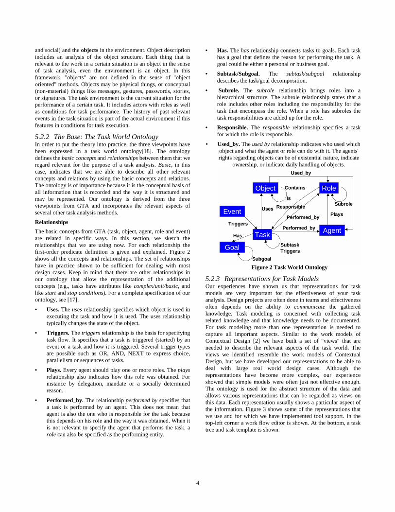
5.2.2 The Base: The Task World Ontology In order to put the theory into practice, the three viewpoints have been expressed in a task world ontology[18]. The ontology defines the basic concepts and relationships between them that we regard relevant for the purpose of a task analysis. Basic, in this case, indicates that we are able to describe all other relevant concepts and relations by using the basic concepts and relations. The ontology is of importance because it is the conceptual basis of all information that is recorded and the way it is structured and may be represented. Our ontology is derived from the three viewpoints from GTA and incorporates the relevant aspects of several other task analysis methods. Relationships The basic concepts from GTA (task, object, agent, role and event) are related in specific ways. In this section, we sketch the relationships that we are using now. For each relationship the first-order predicate definition is given and explained. Figure 2 shows all the concepts and relationships. The set of relationships have in practice shown to be sufficient for dealing with most design cases. Keep in mind that there are other relationships in our ontology that allow the representation of the additional concepts (e.g., tasks have attributes like complex/unit/basic, and like start and stop conditions). For a complete specification of our ontology, see [17].
• Uses. The uses relationship specifies which object is used in executing the task and how it is used. The uses relationship typically changes the state of the object.
• Triggers. The triggers relationship is the basis for specifying task flow. It specifies that a task is triggered (started) by an event or a task and how it is triggered. Several trigger types are possible such as OR, AND, NEXT to express choice, parallelism or sequences of tasks.
• Plays. Every agent should play one or more roles. The plays relationship also indicates how this role was obtained. For instance by delegation, mandate or a socially determined reason.
• Performed_by. The relationship performed by specifies that a task is performed by an agent. This does not mean that agent is also the one who is responsible for the task because this depends on his role and the way it was obtained. When it is not relevant to specify the agent that performs the task, a role can also be specified as the performing entity.
• Has. The has relationship connects tasks to goals. Each task has a goal that defines the reason for performing the task. A goal could be either a personal or business goal.
• Subtask/Subgoal. The subtask/subgoal relationship describes the task/goal decomposition.
• Subrole. The subrole relationship brings roles into a hierarchical structure. The subrole relationship states that a role includes other roles including the responsibility for the task that encompass the role. When a role has subroles the task responsibilities are added up for the role.
• Responsible. The responsible relationship specifies a task for which the role is responsible.
• Used_by. The used by relationship indicates who used which object and what the agent or role can do with it. The agents' rights regarding objects can be of existential nature, indicate
ownership, or indicate daily handling of objects.
Task Agent
Role
Event
Object Contains
Responsible
Performed_by
Plays
Triggers
Subtask
Uses
Triggers
Used_by
SubroleIs
Performed_by
Goal
Has
Subgoal Figure 2 Task World Ontology
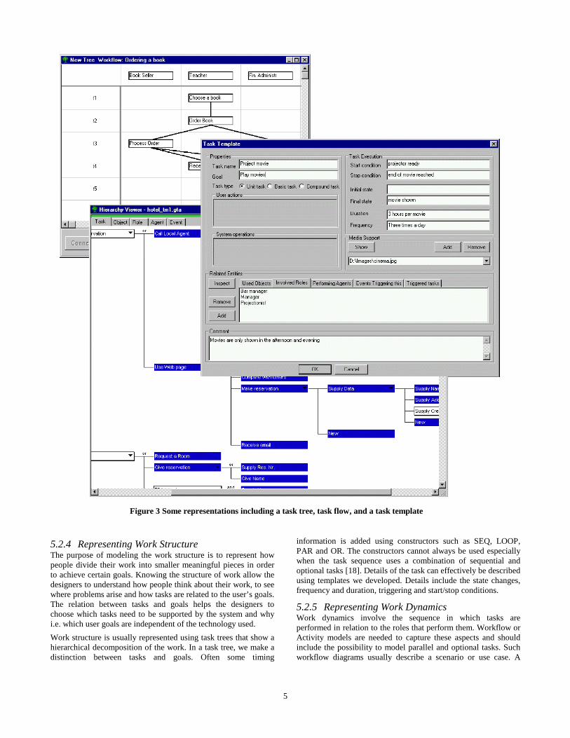
5.2.3 Representations for Task Models Our experiences have shown us that representations for task models are very important for the effectiveness of your task analysis. Design projects are often done in teams and effectiveness often depends on the ability to communicate the gathered knowledge. Task modeling is concerned with collecting task related knowledge and that knowledge needs to be documented. For task modeling more than one representation is needed to capture all important aspects. Similar to the work models of Contextual Design [2] we have built a set of "views" that are needed to describe the relevant aspects of the task world. The views we identified resemble the work models of Contextual Design, but we have developed our representations to be able to deal with large real world design cases. Although the representations have become more complex, our experience showed that simple models were often just not effective enough. The ontology is used for the abstract structure of the data and allows various representations that can be regarded as views on this data. Each representation usually shows a particular aspect of the information. Figure 3 shows some of the representations that we use and for which we have implemented tool support. In the top-left corner a work flow editor is shown. At the bottom, a task tree and task template is shown.
5
5.2.4 Representing Work Structure The purpose of modeling the work structure is to represent how people divide their work into smaller meaningful pieces in order to achieve certain goals. Knowing the structure of work allow the designers to understand how people think about their work, to see where problems arise and how tasks are related to the user’s goals. The relation between tasks and goals helps the designers to choose which tasks need to be supported by the system and why i.e. which user goals are independent of the technology used. Work structure is usually represented using task trees that show a hierarchical decomposition of the work. In a task tree, we make a distinction between tasks and goals. Often some timing
information is added using constructors such as SEQ, LOOP, PAR and OR. The constructors cannot always be used especially when the task sequence uses a combination of sequential and optional tasks [18]. Details of the task can effectively be described using templates we developed. Details include the state changes, frequency and duration, triggering and start/stop conditions.
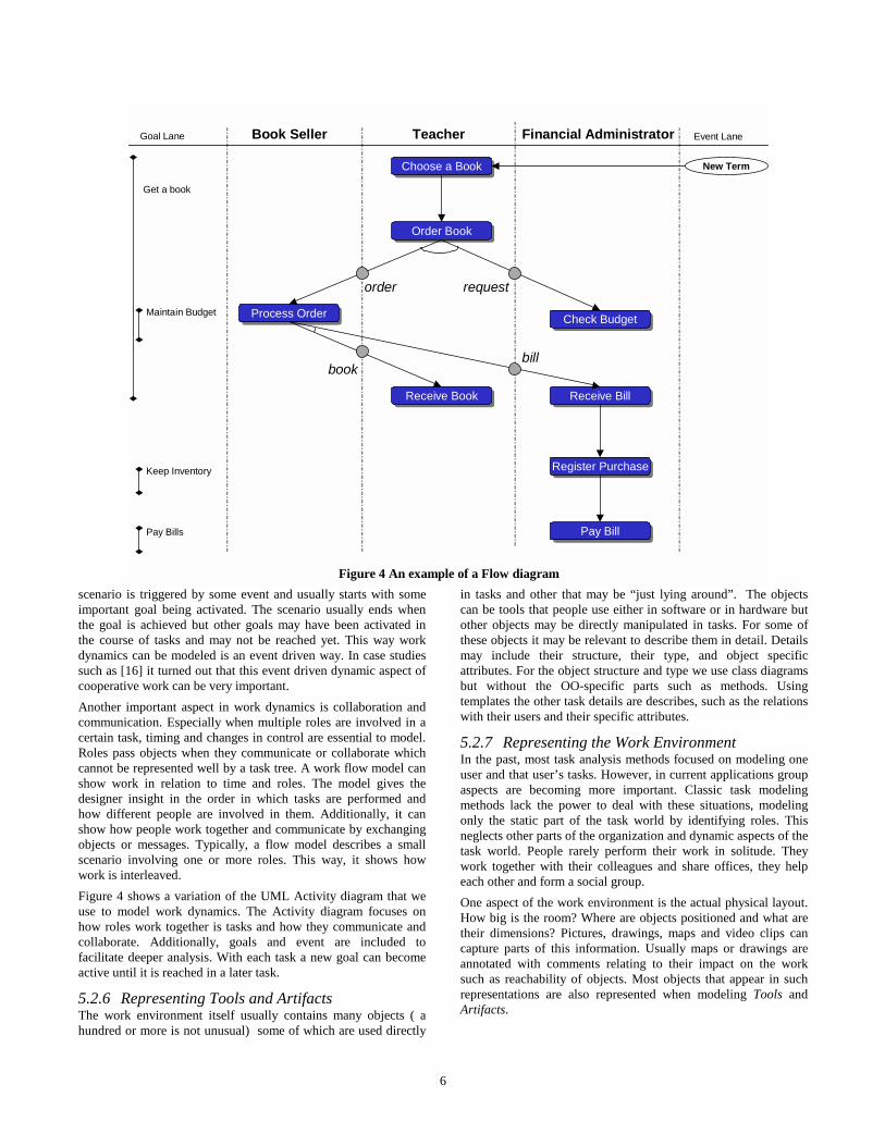
5.2.5 Representing Work Dynamics Work dynamics involve the sequence in which tasks are performed in relation to the roles that perform them. Workflow or Activity models are needed to capture these aspects and should include the possibility to model parallel and optional tasks. Such workflow diagrams usually describe a scenario or use case. A
Figure 3 Some representations including a task tree, task flow, and a task template
6
scenario is triggered by some event and usually starts with some important goal being activated. The scenario usually ends when the goal is achieved but other goals may have been activated in the course of tasks and may not be reached yet. This way work dynamics can be modeled is an event driven way. In case studies such as [16] it turned out that this event driven dynamic aspect of cooperative work can be very important. Another important aspect in work dynamics is collaboration and communication. Especially when multiple roles are involved in a certain task, timing and changes in control are essential to model. Roles pass objects when they communicate or collaborate which cannot be represented well by a task tree. A work flow model can show work in relation to time and roles. The model gives the designer insight in the order in which tasks are performed and how different people are involved in them. Additionally, it can show how people work together and communicate by exchanging objects or messages. Typically, a flow model describes a small scenario involving one or more roles. This way, it shows how work is interleaved. Figure 4 shows a variation of the UML Activity diagram that we use to model work dynamics. The Activity diagram focuses on how roles work together is tasks and how they communicate and collaborate. Additionally, goals and event are included to facilitate deeper analysis. With each task a new goal can become active until it is reached in a later task.
5.2.6 Representing Tools and Artifacts The work environment itself usually contains many objects ( a hundred or more is not unusual) some of which are used directly
in tasks and other that may be “just lying around”. The objects can be tools that people use either in software or in hardware but other objects may be directly manipulated in tasks. For some of these objects it may be relevant to describe them in detail. Details may include their structure, their type, and object specific attributes. For the object structure and type we use class diagrams but without the OO-specific parts such as methods. Using templates the other task details are describes, such as the relations with their users and their specific attributes.
5.2.7 Representing the Work Environment In the past, most task analysis methods focused on modeling one user and that user’s tasks. However, in current applications group aspects are becoming more important. Classic task modeling methods lack the power to deal with these situations, modeling only the static part of the task world by identifying roles. This neglects other parts of the organization and dynamic aspects of the task world. People rarely perform their work in solitude. They work together with their colleagues and share offices, they help each other and form a social group. One aspect of the work environment is the actual physical layout. How big is the room? Where are objects positioned and what are their dimensions? Pictures, drawings, maps and video clips can capture parts of this information. Usually maps or drawings are annotated with comments relating to their impact on the work such as reachability of objects. Most objects that appear in such representations are also represented when modeling Tools and Artifacts.
Book Seller Teacher Financial Administrator
Choose a BookChoose a Book
Check BudgetCheck Budget
Receive BookReceive Book Receive BillReceive Bill
Register PurchaseRegister Purchase
Pay BillPay Bill
Process OrderProcess Order
Order BookOrder Book
New Term
Get a book
Maintain Budget
Keep Inventory
Pay Bills
order
book
request
bill
Goal Lane Event Lane
Figure 4 An example of a Flow diagram
7
Every work environment also has its own culture which defines the values, policies, expectations, and the general approach to work. The culture determines how people work together, how they view each other socially and what they expect from each other. Taking the culture into account for UID may influence decisions on restructuring of work when rearranging roles or their responsibilities. Roles are usually used to describe the formal work structure extended with some ”socially defined” roles. In practice, roles such as ”management” or ”marketing” influence each other and other roles. These kinds of influence relationships are part of the work culture. Describing work culture is not straightforward but at least some influence relationships and their relative strengths can be modeled. Other aspects of culture include policies, values and identity.
5.3 Integrated Representations When multiple representations are used, it is important to integrate these representations. We therefore defined each representation as a view on the data that is structured by our ontology. This way, concepts can appear in several representations at the same time without confusing about the semantics of the representations. For instance, a task is only specified once but can be part of, both, a task tree, a task flow representation, and a role template. Our tools can help designers using different representation while guarding consistency between the representations. Using our tool the ontology remains hidden within the tool and designers are just editing representations. This way representations are "integrated" without extra effort from designers. The tool saves time and designers can concentrate on modeling rather than editing activities. Besides representations based on the ontology we also capture data from ethnographic studies. This data includes video fragments, sound clips and images of objects. Using our tool, this data is linked to one or more of the concepts of the ontology. For instance, a short video clip can give an impression of how the
work is actually done in the current situation. We will discuss tools more in the section on supporting the design process.
6. DETAILED DESIGN, THE UVM 6.1 The Process After the task modeling activity the actual Groupware system needs to be designed and specified. Task model 2 gives the envisioned task world where the new system will be situated. From there, the details of the technology and the basic tasks that involve interaction with a Groupware system need to be worked out. This activity consists of three sub-activities that are strongly interrelated: specifying of the functionality, structuring the dialog between the users and the system, and specifying the way the system is represented to the user. This activity is focused on a detailed description of the system as far as it is of direct relevance to the end-user. We use the term User Virtual Machine [12](UVM) to indicate the total of user relevant knowledge of the technology, both semantics (what the system offers the user for task delegation) and syntax (how task delegation to the system has to be expressed by the user). This resembles Constantine’s intention with essential modeling where he emphasizes modeling the tasks of the users without using particular technology solutions. In actual design, frequent iterations will be needed between the specifications of the tasks models and the UVM specifications. This iteration is an explicit part of the method and essential for the development of usable systems. When making the transition from task model 2 to designing the UVM, the tasks and the objects determine to first sketch of the application. The task or object structure is used to create the main displays and navigational structure. From there on, the iterative refinement process takes off.
Figure 5 An editor for UAN diagrams
8
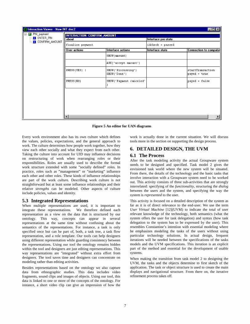
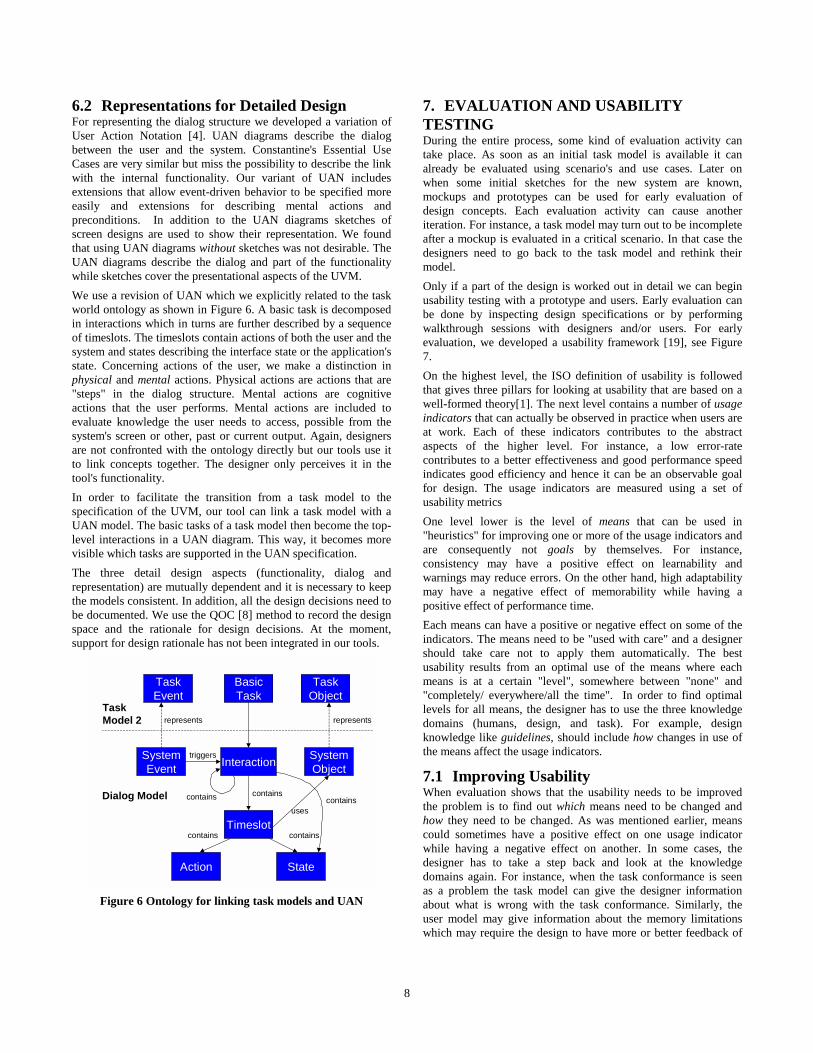
6.2 Representations for Detailed Design For representing the dialog structure we developed a variation of User Action Notation [4]. UAN diagrams describe the dialog between the user and the system. Constantine's Essential Use Cases are very similar but miss the possibility to describe the link with the internal functionality. Our variant of UAN includes extensions that allow event-driven behavior to be specified more easily and extensions for describing mental actions and preconditions. In addition to the UAN diagrams sketches of screen designs are used to show their representation. We found that using UAN diagrams without sketches was not desirable. The UAN diagrams describe the dialog and part of the functionality while sketches cover the presentational aspects of the UVM. We use a revision of UAN which we explicitly related to the task world ontology as shown in Figure 6. A basic task is decomposed in interactions which in turns are further described by a sequence of timeslots. The timeslots contain actions of both the user and the system and states describing the interface state or the application's state. Concerning actions of the user, we make a distinction in physical and mental actions. Physical actions are actions that are "steps" in the dialog structure. Mental actions are cognitive actions that the user performs. Mental actions are included to evaluate knowledge the user needs to access, possible from the system's screen or other, past or current output. Again, designers are not confronted with the ontology directly but our tools use it to link concepts together. The designer only perceives it in the tool's functionality. In order to facilitate the transition from a task model to the specification of the UVM, our tool can link a task model with a UAN model. The basic tasks of a task model then become the top-level interactions in a UAN diagram. This way, it becomes more visible which tasks are supported in the UAN specification. The three detail design aspects (functionality, dialog and representation) are mutually dependent and it is necessary to keep the models consistent. In addition, all the design decisions need to be documented. We use the QOC [8] method to record the design space and the rationale for design decisions. At the moment, support for design rationale has not been integrated in our tools.
triggers
uses
Dialog Model
TaskModel 2
contains contains
containscontainscontains
represents represents
BasicTask
TaskEvent
TaskObject
Action
SystemObjectInteractionSystem
Event
Timeslot
State
Figure 6 Ontology for linking task models and UAN
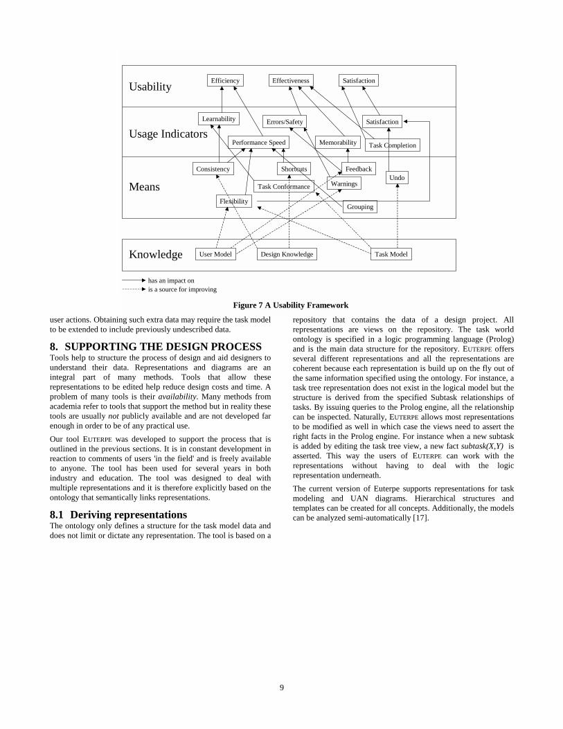
7. EVALUATION AND USABILITY TESTING During the entire process, some kind of evaluation activity can take place. As soon as an initial task model is available it can already be evaluated using scenario's and use cases. Later on when some initial sketches for the new system are known, mockups and prototypes can be used for early evaluation of design concepts. Each evaluation activity can cause another iteration. For instance, a task model may turn out to be incomplete after a mockup is evaluated in a critical scenario. In that case the designers need to go back to the task model and rethink their model. Only if a part of the design is worked out in detail we can begin usability testing with a prototype and users. Early evaluation can be done by inspecting design specifications or by performing walkthrough sessions with designers and/or users. For early evaluation, we developed a usability framework [19], see Figure 7. On the highest level, the ISO definition of usability is followed that gives three pillars for looking at usability that are based on a well-formed theory[1]. The next level contains a number of usage indicators that can actually be observed in practice when users are at work. Each of these indicators contributes to the abstract aspects of the higher level. For instance, a low error-rate contributes to a better effectiveness and good performance speed indicates good efficiency and hence it can be an observable goal for design. The usage indicators are measured using a set of usability metrics One level lower is the level of means that can be used in "heuristics" for improving one or more of the usage indicators and are consequently not goals by themselves. For instance, consistency may have a positive effect on learnability and warnings may reduce errors. On the other hand, high adaptability may have a negative effect of memorability while having a positive effect of performance time. Each means can have a positive or negative effect on some of the indicators. The means need to be "used with care" and a designer should take care not to apply them automatically. The best usability results from an optimal use of the means where each means is at a certain "level", somewhere between "none" and "completely/ everywhere/all the time". In order to find optimal levels for all means, the designer has to use the three knowledge domains (humans, design, and task). For example, design knowledge like guidelines, should include how changes in use of the means affect the usage indicators.
7.1 Improving Usability When evaluation shows that the usability needs to be improved the problem is to find out which means need to be changed and how they need to be changed. As was mentioned earlier, means could sometimes have a positive effect on one usage indicator while having a negative effect on another. In some cases, the designer has to take a step back and look at the knowledge domains again. For instance, when the task conformance is seen as a problem the task model can give the designer information about what is wrong with the task conformance. Similarly, the user model may give information about the memory limitations which may require the design to have more or better feedback of
9
user actions. Obtaining such extra data may require the task model to be extended to include previously undescribed data.
8. SUPPORTING THE DESIGN PROCESS Tools help to structure the process of design and aid designers to understand their data. Representations and diagrams are an integral part of many methods. Tools that allow these representations to be edited help reduce design costs and time. A problem of many tools is their availability. Many methods from academia refer to tools that support the method but in reality these tools are usually not publicly available and are not developed far enough in order to be of any practical use. Our tool EUTERPE was developed to support the process that is outlined in the previous sections. It is in constant development in reaction to comments of users 'in the field' and is freely available to anyone. The tool has been used for several years in both industry and education. The tool was designed to deal with multiple representations and it is therefore explicitly based on the ontology that semantically links representations.
8.1 Deriving representations The ontology only defines a structure for the task model data and does not limit or dictate any representation. The tool is based on a
repository that contains the data of a design project. All representations are views on the repository. The task world ontology is specified in a logic programming language (Prolog) and is the main data structure for the repository. EUTERPE offers several different representations and all the representations are coherent because each representation is build up on the fly out of the same information specified using the ontology. For instance, a task tree representation does not exist in the logical model but the structure is derived from the specified Subtask relationships of tasks. By issuing queries to the Prolog engine, all the relationship can be inspected. Naturally, EUTERPE allows most representations to be modified as well in which case the views need to assert the right facts in the Prolog engine. For instance when a new subtask is added by editing the task tree view, a new fact subtask(X,Y) is asserted. This way the users of EUTERPE can work with the representations without having to deal with the logic representation underneath. The current version of Euterpe supports representations for task modeling and UAN diagrams. Hierarchical structures and templates can be created for all concepts. Additionally, the models can be analyzed semi-automatically [17].
Effectiveness Satisfaction
Learnability Satisfaction
MemorabilityPerformance Speed
Errors/Safety
Consistency Feedback
Warnings
ShortcutsUndo
Task Conformance
EfficiencyUsability
Usage Indicators
Means
User Model Task ModelDesign KnowledgeKnowledge
Flexibility
has an impact onis a source for improving
Grouping
Task Completion
Figure 7 A Usability Framework
10
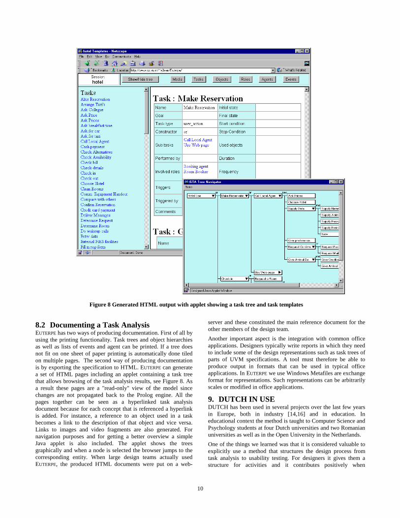
8.2 Documenting a Task Analysis EUTERPE has two ways of producing documentation. First of all by using the printing functionality. Task trees and object hierarchies as well as lists of events and agent can be printed. If a tree does not fit on one sheet of paper printing is automatically done tiled on multiple pages. The second way of producing documentation is by exporting the specification to HTML. EUTERPE can generate a set of HTML pages including an applet containing a task tree that allows browsing of the task analysis results, see Figure 8. As a result these pages are a "read-only" view of the model since changes are not propagated back to the Prolog engine. All the pages together can be seen as a hyperlinked task analysis document because for each concept that is referenced a hyperlink is added. For instance, a reference to an object used in a task becomes a link to the description of that object and vice versa. Links to images and video fragments are also generated. For navigation purposes and for getting a better overview a simple Java applet is also included. The applet shows the trees graphically and when a node is selected the browser jumps to the corresponding entity. When large design teams actually used EUTERPE, the produced HTML documents were put on a web-
server and these constituted the main reference document for the other members of the design team. Another important aspect is the integration with common office applications. Designers typically write reports in which they need to include some of the design representations such as task trees of parts of UVM specifications. A tool must therefore be able to produce output in formats that can be used in typical office applications. In EUTERPE we use Windows Metafiles are exchange format for representations. Such representations can be arbitrarily scales or modified in office applications.
9. DUTCH IN USE DUTCH has been used in several projects over the last few years in Europe, both in industry [14,16] and in education. In educational context the method is taught to Computer Science and Psychology students at four Dutch universities and two Romanian universities as well as in the Open University in the Netherlands. One of the things we learned was that it is considered valuable to explicitly use a method that structures the design process from task analysis to usability testing. For designers it gives them a structure for activities and it contributes positively when
Figure 8 Generated HTML output with applet showing a task tree and task templates
11
negotiating with higher management, for example for getting support for data gathering activities. During the analysis phase the GTA conceptual framework proved to be of great value. It worked as a kind of 'check-list' to focus attention to things that matter in performing tasks. Some activities such as ethnographic studies and interaction analysis are often new to analysts but after the initial hurdle the benefits are clear. It helps creating a common vocabulary and simplifies discussions. The representations have been evolving a lot but they now seem to be powerful enough for practical use. However, tool support is essential for creating and managing these representations. Because of the required iterations in the design process, the tools save designers a lot of time. When using our tool we saw that it was important to keep editing functionality simple so that the more advanced features are not directly visible. However, what sometimes remains difficult is the 'awareness’ in the company of what it means to perform task analysis at the customer site and how it should be integrated in the already present system design culture. To the majority of traditional IT-personal and organisations it is radically new. It takes time to let this awareness grow by (partly) applying the method in current projects.
10. DISCUSSION Although design methods exist that claim to cover similar design aspects, we found that an integrating method is what many designers ask for. In comparison to other design approaches like the ones mentioned in Table 1, our approach differs on three main points: - DUTCH uses multiple representations integrated through use
of an ontology. The representations have been used frequently and have proven to be sufficient for most design cases.
- DUTCH has a wider scope than most other methods ranging from initial task analysis and envisioning to detailed design and evaluation. It considers both multiple and individual users.
- DUTCH is supported by tools that are publicly available and tested in practice.
An integrated method is desirable when the method is applied in practice and consequently the gap between theory and practice is reduced. For example, when we work together with industry we found that having tool-support is an important issue. Being able to manage to data and design representations using a tool can save a lot of time. Such benefits contribute when higher management needs to be convinced that it is important to do structured task-based design.
11. CONCLUSIONS We have outlined an approach for task based Groupware design that combines known theoretical insights into one coherent and practical method. The method is used in several countries in Europe both in industry and education. The method defines a clear process, models and representations to be used and tools that support the design process.
12. REFERENCES [1] Bevan, N. (1994), Guidance on Usability, ISO 9241-
11 Ergonomic Requirements for Office Work With VDTs..
[2] Beyer, H. and Holtzblatt, K. (1998), Contextual Design, Morgan Kaufmann Publishers.
[3] Constantine, L. L. and Lockwood, L. A. D. (1999), Software for Use, Addison Wesley.
[4] Hix, D. and Hartson, H. R. (1993), Developing User Interfaces : Ensuring Usability Through Product & Process. John Wiley & Sons, Inc.
[5] Johnson, P., Johnson, H., Waddington, R. and Shouls, A. (1988), Task-Related Knowledge Structures: Analysis, Modeling and Application, in: Jones, D. M. and Winder, R., People and Computers IV pp. 35-62, University Press, Cambridge.
[6] Jordan , B. (1996), Ethnographic Workplace Studies and CSCW, in: D. Shapiro, M. J. Tauber and R. Traunmueller, The Design of Computer Supported Cooperative Work and Groupware Systems , North-Holland, Amsterdam.
[7] Kieras, D. and Polson, P.G. (1985), An approach to the formal analysis of user complexity, International Journal of Man-Machine Studies, vol 22, no. 365-394.
[8] MacLean, A., Young, R., Bellotti, V. and Moran, T. (1991), Questions, options, and criteria: elements of design space analysis., Human Computer Interaction, vol 6, no. 3 & 4, pp.201-250.
[9] Paterno, F. D., Mancini, C., and Meniconi, S. (1997), ConcurTaskTrees: A Diagrammatic Notation for Specifying Task Models, Proceedings of Interact '97, Sydney, Chapman & Hall.
[10] Scapin, D. and Pierret-Golbreich, C. (1989), Towards a method for Task Description: MAD, in: Berlinguet, L. and Berthelette, D., Work With Display Units 89 , Elsevier, Amsterdam.
[11] Sebillotte, S. (1988), Hierarchical planning as a method for task-analysis: the example of office task analysis, Behaviour and Information Technology, vol 7(3), no. 275-293.
[12] Tauber, M.J. (1988), On mental models and the user interface, in: van der Veer, G. C., Green, T. R. G., Hoc, J-M., and Murray, D., Working With Computers: Theory Versus Outcome , Academic Press, London.
[13] Tauber, M. J. (1990), ETAG: Extended Task Action Grammar - a language for the description of the user's task language, Proceedings of INTERACT '90, Amsterdam, Elsevier, Amsterdam.
[14] van der Veer, G. C., Hoeve, M., and Lenting, B. F. (1996), Modeling complex work systems - method
12
meets reality , 8th European Conference on Cognitive Ergonomics (EACE) , Inria, Le Chesnay cedex.
[15] Van der Veer, G. C., van Vliet, J. C., and Lenting, B. F. (1995), Designing complex systems - a structured activity, DIS'95, Symposium on Designing Interactive Systems, ACM Press, New York.
[16] van Loo, Reinard, van der Veer, G. C., and van Welie, M. (1999), Groupware Task Analysis in Practice: a scientific approach meets security problems, 7th European Conference on Cognitive Science Approaches to Process Control , Villeneuve d'Ascq, France .
[17] van Welie, M., van der Veer, G. C., and Eliëns, A. (1998), Euterpe - Tool support for analyzing cooperative environments, Ninth European Conference on Cognitive Ergonomics, Limerick, Ireland.
[18] van Welie, M., van der Veer, G. C., and Eliëns, A. (1998), An Ontology for Task World Models, Proceedings of DSV-IS98, Abingdon UK, Springer-Verlag, Wien.
[19] van Welie, M., van der Veer, G. C., and Eliëns, A. (1999), Breaking down Usability, Proceedings of Interact '99, Edinburgh, Scotland.