Embed Size (px)
Citation preview
TB 11-5820-890-20-11
1 AUGUST 1999
TECHNICAL BULLETIN
COMBAT NET RADIO
INSTALLATION INSTRUCTIONS FOR
INSTALLATION KIT, ELECTRONIC EQUIPMENT
MK-2204/VRC (NSN 5895-01-225-8658) (EIC: N/A)
TO PERMIT INSTALLATION OF
RADIO SET AN/VRC-87/88/90 SERIES
IN A
TRUCK, TANKER, FUEL: 10 TON, 8x8, M978
TRUCK, WRECKER: 10 TON, 8x8, M984
TRUCK, CARGO: 10 TON, 8x8, M985
Approved for public release; distribution is unlimited.
HEADQUARTERS, DEPARTMENT OF THE ARMY
TECHNICAL BULLETIN
NO. 11-5820-890-20-11
*TB 11–5820–890–20–11HEADQUARTERS,
DEPARTMENT OF THE ARMYWASHINGTON, DC, 1 AUGUST 1999
i
INSTALLATION INSTRUCTIONS FORINSTALLATION KIT, ELECTRONIC EQUIPMENT
MK-2204/VRC (NSN 5895-01-225-8658) (EIC: N/A)TO PERMIT INSTALLATION OF
RADIO SET AN/VRC-87/88/90 SERIES
IN ATRUCK, TANKER, FUEL: 10 TON, 8x8, M978
TRUCK,WRECKER: 10 TON, 8x8, M984
TRUCK, CARGO: 10 TON, 8x8, M985
REPORTING OF ERRORS AND RECOMMENDING IMPROVEMENTS
You can help improve this manual. If you find any mistakes, or if you know of a way to improve the procedures, pleaselet us know. Mail your letter, DA Form 2028 (Recommended Changes to Publications and Blank Forms) or DA 2028–2located in back of this manual direct to: Commander, US Army Communications–Electronics Command Fort Mon-mouth, ATTN: AMSEL–LC–LEO–D–CS–CFO, Fort Monmouth, New Jersey 07703–5000. The Fax number is732–532–1413, DSN 992–1413. You may also e–mail your recommendation to AMSEL–LC–LEO–PUBS–[email protected].
In either case a reply will be furnished direct to you.
TABLE OF CONTENTS
Subject Section Page
Scope 0.1 1. . . . . . . . . . . . . . . . . . . . . . . . . . . . . . . . . . . . . . . . . . . . . . . . . . . . . . . . . . . . . . . .
General Information 0.2 1. . . . . . . . . . . . . . . . . . . . . . . . . . . . . . . . . . . . . . . . . . . . . . . . . . . .
Maintenance Forms, Records, and Reports 0.3 1. . . . . . . . . . . . . . . . . . . . . . . . . . . . . . . .
Reports of Maintenance and Unsatisfactory Equipment 0.3.1 1. . . . . . . . . . . . . . . . . . . . .
Report of Packing and Handling Deficiencies 0.3.2 1. . . . . . . . . . . . . . . . . . . . . . . . . . . . . .
Discrepancy in Transportation Deficiency Report (TDR) (SF 361) 0.3.3 1. . . . . . . . . . . . .
Consolidated Index of Army Publications 0.4 1. . . . . . . . . . . . . . . . . . . . . . . . . . . . . . . . . .
Purpose of Installation 1. 2. . . . . . . . . . . . . . . . . . . . . . . . . . . . . . . . . . . . . . . . . . . . . . . . . .
End Item or System to be Modified 2. 2. . . . . . . . . . . . . . . . . . . . . . . . . . . . . . . . . . . . . . .
Application Times 3. 2. . . . . . . . . . . . . . . . . . . . . . . . . . . . . . . . . . . . . . . . . . . . . . . . . . . . . .
Time for Completion of Installation 3.1 2. . . . . . . . . . . . . . . . . . . . . . . . . . . . . . . . . . . . . . . .
Time for Installation of One Assembly or Component 3.2 2. . . . . . . . . . . . . . . . . . . . . . .
Preparation for Installation 4. 2. . . . . . . . . . . . . . . . . . . . . . . . . . . . . . . . . . . . . . . . . . . . . . .
Preparation of Vehicle 4.1 2. . . . . . . . . . . . . . . . . . . . . . . . . . . . . . . . . . . . . . . . . . . . . . . . . .
Preparation of MK 4.2 2. . . . . . . . . . . . . . . . . . . . . . . . . . . . . . . . . . . . . . . . . . . . . . . . . . . . . .
MK, Distribution, and Consumables 4.3 3. . . . . . . . . . . . . . . . . . . . . . . . . . . . . . . . . . . . . .
Tools and Test, Measurement, and Diagnostic Equipment (TMDE)
Required 4.4 7. . . . . . . . . . . . . . . . . . . . . . . . . . . . . . . . . . . . . . . . . . . . . . . . . . . . . . . . . . . . . .
Installation Procedures 5. 8. . . . . . . . . . . . . . . . . . . . . . . . . . . . . . . . . . . . . . . . . . . . . . . . . .
Installation of Antenna AS-3900/VRC (antenna) 5.1 10. . . . . . . . . . . . . . . . . . . . . . . . . . .
Installation of Antenna Base 5.1.1 10. . . . . . . . . . . . . . . . . . . . . . . . . . . . . . . . . . . . . . . . . . . . .
Installation of Top Antenna Assembly 5.1.2 12. . . . . . . . . . . . . . . . . . . . . . . . . . . . . . . . . . . . .
Installation of Mounting Base, Electrical Equipment MT-6352/VRC 5.2 13. . . . . . . . . .
(mounting base)
Installation of Cables 5.3 15. . . . . . . . . . . . . . . . . . . . . . . . . . . . . . . . . . . . . . . . . . . . . . . . . . .
Installation of Loudspeaker, Permanent Magnet LS-454/U (speaker) 5.4 18. . . . . . . . .
Installation of Loudspeaker, Control-Unit LS-671/VRC 5.5 19. . . . . . . . . . . . . . . . . . . .
Post-Installation and Checkout 5.6 20. . . . . . . . . . . . . . . . . . . . . . . . . . . . . . . . . . . . . . . . . .
Appendix A. References A1. . . . . . . . . . . . . . . . . . . . . . . . . . . . . . . . . . . . . . . . . . . . . . .
_______________
*This manual supersedes TB 11–5820–890–20–11, dated 1 September 1993
TB 11-5820-890-20-11
ii
LIST OF ILLUSTRATIONS
Figure Title Page
4-1 MK Illustrated Parts List 5. . . . . . . . . . . . . . . . . . . . . . . . . . . . . . . . . . . . . . . . . . . . . . . . . . . . . . . . . . .
4-2 Illustrated Parts List for Table 4-2 6. . . . . . . . . . . . . . . . . . . . . . . . . . . . . . . . . . . . . . . . . . . . . . . . . .
5-1(1) MK and Radio Installation: MK Equipment Locations 8. . . . . . . . . . . . . . . . . . . . . . . . . . . . . . . . .
5-1(2) MK and Radio Installation: Radio Equipment Locations 9. . . . . . . . . . . . . . . . . . . . . . . . . . . . . . .
5-3 Top Antenna Assembly Installation 12. . . . . . . . . . . . . . . . . . . . . . . . . . . . . . . . . . . . . . . . . . . . . . . . .
5-4 Mounting Base Installation 13. . . . . . . . . . . . . . . . . . . . . . . . . . . . . . . . . . . . . . . . . . . . . . . . . . . . . . . .
5-5(1) Cable Installation: Drilling Grommet Hole 15. . . . . . . . . . . . . . . . . . . . . . . . . . . . . . . . . . . . . . . . . . .
5-5(2) Cable Installation: Power and RF Cabling 16. . . . . . . . . . . . . . . . . . . . . . . . . . . . . . . . . . . . . . . . . . .
5-6(1) Speaker Installation-A 18. . . . . . . . . . . . . . . . . . . . . . . . . . . . . . . . . . . . . . . . . . . . . . . . . . . . . . . . . . .
5-6(2) Speaker Installation-B 18. . . . . . . . . . . . . . . . . . . . . . . . . . . . . . . . . . . . . . . . . . . . . . . . . . . . . . . . . . .
5-7 Installation of Loudspeaker, Control-Unit LS-671/VRC 19. . . . . . . . . . . . . . . . . . . . . . . . . . . . . .
5-8 Cable Diagram: For AN/VRC–87/88/90 Series 21. . . . . . . . . . . . . . . . . . . . . . . . . . . . . . . . . . . . . .
LIST OF TABLES
Number Title Page
4-1 Parts List for Installation of Radio Set AN/VRC-87/88/90 Series 4. . . . . . . . . . . . . . . . . . . . . . .
4-2 Additional Items Required for Installation of �D/F" Radio Sets 8. . . . . . . . . . . . . . . . . . . . . . . . . .
TB 11-5820-890-20-11
1
0.1 SCOPE
This technical bulletin provides Installation Instructions for Electronic Equipment MK-2204/VRC, commonly
referred to as the Mounting Kit (MK). The MK shall be installed into the following type of vehicle(s):
� Truck, Tanker, Fuel:10 Ton, 8x8, M978
� Truck, Tanker, Wrecker:10 Ton, 8x8, M984
� Truck, Tanker, Cargo:10 Ton, 8x8, M985
The MK is used for installation of radio set components at field locations. The information contained in this technical
bulletin is the official authorization to perform the installation at the unit maintenance level.
NOTES
� This technical bulletin is not an authorization for requisition or turn-in of vehicles.
� This technical bulletin does not establish quantity or types of vehicles assigned to using units.
This technical bulletin does not contain information on the maintenance or replacement of the MKs. This information
is contained in the MAC of TM 11-5820-890-20-2 and RPSTL of TM 11-5820-890-20P.
0.2 GENERAL INFORMATION.
The MK becomes operable when all the radio set components are installed in the vehicle and correct power is
supplied. Refer to TM 11-5820-890-20-1 or TM 11-5820-890-20-2 for installation, Operational (OP) Check
instructions, and required maintenance procedures. Refer to TM 11-5820-890-20P for repair parts.
Included in the Radio Set AN/VRC-87/88/90 Series is:
� Radio Set AN/VRC-87/88/90 Series (for RT-1523(C)/U)
0.3 MAINTENANCE FORMS, RECORDS, AND REPORTS.
0.3.1 Reports of Maintenance and Unsatisfactory Equipment. See section 4.2.2.3 for information.
0.3.2 Report of Packaging and Handling Deficiencies. See section 4.2.2.1 for information.
0.3.3 Discrepancy in Transportation Deficiency Report (TDR) (SF361). See section 4.2.2.2 for information.
0.4 CONSOLIDATED INDEX OF ARMY PUBLICATIONS.
Refer to the latest issue of DA Pam 25-30 to determine whether there are new changes, or additional publications
pertaining to the equipment.
TB 11-5820-890-20-11
2
1. PURPOSE OF INSTALLATION.
The Electronic Equipment MK-2204/VRC (MK) contains the items needed to mount Radio Set AN/VRC- 87/88/90
Series in a Truck, Tanker, Fuel: 10 Ton, 8x8, M978; Truck, Wrecker : 10 Ton, 8x8, M984; Truck, Cargo: 10 Ton, 8x8,
M985.
2. END ITEM OR SYSTEM TO BE MODIFIED.
Not applicable.
3. APPLICATION TIMES.
3.1�Time for Completion of Installation. Using two people, a total of 2.5 work hours is required. Typical vehicle
downtime is 3.0 hours.
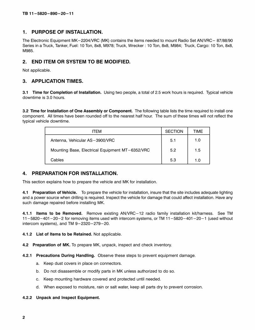
3.2 Time for Installation of One Assembly or Component. The following table lists the time required to install one
component. All times have been rounded off to the nearest half hour. The sum of these times will not reflect the
typical vehicle downtime.
ITEM SECTION TIME
Antenna, Vehicular AS-3900/VRC
Mounting Base, Electrical Equipment MT-6352/VRC
Cables
5.1
5.2
5.3
1.0
1.5
1.0
4.�PREPARATION FOR INSTALLATION.
This section explains how to prepare the vehicle and MK for installation.
4.1�Preparation of Vehicle.�To prepare the vehicle for installation, insure that the site includes adequate lighting
and a power source when drilling is required. Inspect the vehicle for damage that could affect installation. Have any
such damage repaired before installing MK.
4.1.1�Items to be Removed.�Remove existing AN/VRC-12 radio family installation kit/harness. See TM
11-5820-401-20-2 for removing items used with intercom systems, or TM 11-5820-401-20-1 (used without
intercom systems), and TM 9-2320-279-20.
4.1.2�List of Items to be Retained. Not applicable.
4.2�Preparation of MK. To prepare MK, unpack, inspect and check inventory.
4.2.1�Precautions During Handling. Observe these steps to prevent equipment damage.
a.�Keep dust covers in place on connectors.
b.�Do not disassemble or modify parts in MK unless authorized to do so.
c.�Keep mounting hardware covered and protected until needed.
d.�When exposed to moisture, rain or salt water, keep all parts dry to prevent corrosion.
4.2.2�Unpack and Inspect Equipment.
TB 11-5820-890-20-11
3
4.2.2.1�Inspect Packaging for Evidence of Damage. Any shipping damage should be reported on SF364 Report
of Discrepancy (ROD) as prescribed in AR 735-11-2/DLAR 4140.55/NAVMATINST 4355.73A/AFR 400-64/MCO
4430.3F.
4.2.2.2�Unpack and Inventory MK. If any item is missing, fill out and forward Transportation Deficiency Report
(TDR) (SF361) as described in AR 55-38/NAVSUPINST 4610.33C/AFR 75-18/MCO P4610.19D/DLAR 4500.15.
4.2.2.3�Examine Each Item for Damage. If any item is damaged, fill out and forward SF364 Report of Discrepancy
(ROD) as prescribed in AR 735-11-2/DLAR 4140.55/NAVMATINST 4355.73A/AFR 400-64/MCO 4430.3F. All
damages should be reported as prescribed by DA Pam 738-750, as contained in Maintenance Management
Update.
4.3�MK, Distribution, and Consumables.
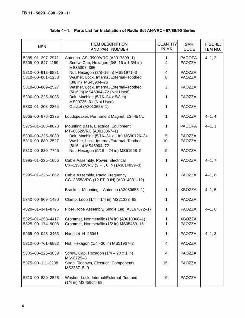
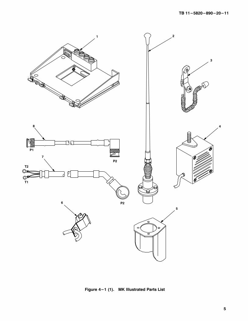
4.3.1�Items Supplied in MK and/or Required for Installation. Use Table 4-1 and figure 4-1 to identify and
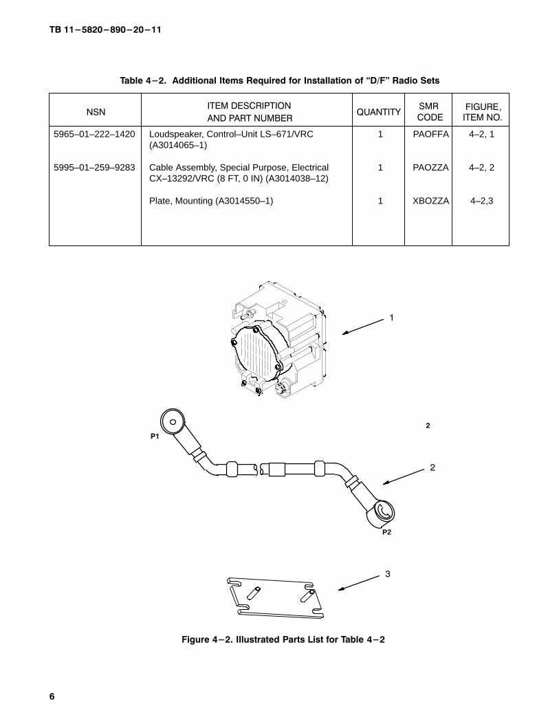
inventory MK parts supplied to install Radio Set AN/VRC-87/88/90 Series. Refer to Table 4-2 and Figure 4-2 to
identify additional items required to install for �D/F" Series Radio Sets.
4.3.2�Distribution and Issue Instructions.
a.�US Forces: Do not requisition MK. They will be shipped automatically.
b.�US Army Depots: Requisition MK through supply channels.
c.�Multiservice: Instructions shall be included for multiservice modifications.
d.�MAP/MAS Countries: Instructions shall be provided for MAP/MAS countries.
TB 11-5820-890-20-11
4
Table 4-1. Parts List for Installation of Radio Set AN/VRC-87/88/90 Series���������������������������
NSNAND PART NUMBER
ITEM DESCRIPTION QUANTITY SMR
CODE
FIGURE,
ITEM NO.
5985–01–297–2971 Antenna AS–3900/VRC (A3017899–1) 1 PAOOFA 4–1, 25305–00–847–1159 Screw, Cap, Hexagon (3/8–16 x 1 3/4 in) 4 PAOZZA
MS35307–3655310–00–913–8881 Nut, Hexagon (3/8–16 in) MS51971–3 4 PAOZZA5310–00–061–1258 Washer, Lock, Internal/External–Toothed 8 PAOZZA
(3/8 in) MS45904–76 5310–00–889–2527 Washer, Lock, Internal/External–Toothed 2 PAOZZA
(5/16 in) MS45904–72 (Not Used)5306–00–225–9086 Bolt, Machine (5/16–24 x 5/8 in) 1 PAOZZA
MS90726–31 (Not Used)5330–01–205–2864 Gasket (A3013655–1) 1 PAOZZA
5965–00–876–2375 Loudspeaker, Permanent Magnet LS–454/U 1 PAOZZA 4–1, 4
5975–01–188–8873 Mounting Base, Electrical Equipment 1 PAOOFA 4–1, 1MT–6352/VRC (A3013367–1)
5306–00–225–9089 Bolt, Machine (5/16–24 x 1 in) MS90726–34 5 PAOZZA5310–00–889–2527 Washer, Lock, Internal/External–Toothed 10 PAOZZA
(5/16 in) MS45904–72 5310–00–880–7746 Nut, Hexagon (5/16 – 24 in) MS51968–5 5 PAOZZA
5995–01–225–1656 Cable Assembly, Power, Electrical 1 PAOZZA 4–1, 7CX–13302/VRC (3 FT, 0 IN) (A3014039–3)
5995–01–225–1662 Cable Assembly, Radio Frequency 1 PAOZZA 4–1, 8CG–3855/VRC (12 FT, 0 IN) (A3014031–12)
Bracket, Mounting – Antenna (A3050655–1) 1 XBOZZA 4–1, 5
5340–00–809–1490 Clamp, Loop (1/4 – 1/4 in) MS21333–98 1 PAOZZA
4020–01–341–8795 Fiber Rope Assembly, Single Leg (A3167672–1) 1 PAOZZA 4–1, 6
5325–01–253–4417 Grommet, Nonmetallic (1/4 in) (A3013068–1) 1 XBOZZA5325–00–174–9008 Grommet, Nonmetallic (1/2 in) MS35489–15 1 PAOZZA
5965–00–043–3463 Handset H–250/U 1 PAOZZA 4–1, 3
5310–00–761–6882 Nut, Hexagon (1/4 –20 in) MS51967–2 4 PAOZZA
5305–00–225–3839 Screw, Cap, Hexagon (1/4 – 20 x 1 in) 4 PAOZZAMS90725–8
5975–00–111–3208 Strap, Tiedown, Electrical Components 15 PAOZZAMS3367–5–9
5310–00–889–2528 Washer, Lock, Internal/External–Toothed 9 PAOZZA(1/4 in) MS45904–68
IN MK
TB 11-5820-890-20-11
5
3
1
5
7
4
T2
T1
8
P2
P2
P1
6
2
Figure 4-1 (1).�MK Illustrated Parts List
TB 11-5820-890-20-11
6
Table 4-2. Additional Items Required for Installation of �D/F" Radio Sets
NSNAND PART NUMBER
ITEM DESCRIPTIONQUANTITY
CODE
SMR
ITEM NO.FIGURE,
2
Figure 4-2. Illustrated Parts List for Table 4-2
P1
P2
2
1
3
5965–01–222–1420 Loudspeaker, Control–Unit LS–671/VRC 1 PAOFFA 4–2, 1(A3014065–1)
5995–01–259–9283 Cable Assembly, Special Purpose, Electrical 1 PAOZZA 4–2, 2CX–13292/VRC (8 FT, 0 IN) (A3014038–12)
Plate, Mounting (A3014550–1) 1 XBOZZA 4–2,3
TB 11-5820-890-20-11
7
4.3.3�Consumable Materials. The table below lists materials required for installation but not supplied with MK.
NSN NOMENCLATURE
8040-00-117-8510
6850-00-880-7616
8030-00-292-1102
Adhesive-Sealant, Clear, RTV
Silicone Compound, MIL-S-8660
Conductive Anti-seize Compound
4.4�Tools and Test, Measurement, and Diagnostic Equipment (TMDE) Required. The following tools and
TMDE are needed for installation.
Radio Set*
Electric Grinder or Equivalent
Pocket Knife, Electrician's
Screwdriver, No. 2 Point Phillips, 4 in
Screwdriver, 1/4 in Flatblade, 4 in
Pliers, Round Nose
Pliers, Diagonal Cutting
Wrench, Open/Box: 7/16 in
1/2 in9/16 in
3/8 in
Handle, Socket Wrench
Socket: 7/16 in1/2 in
9/16 in
3/8 in
Electric Drill
Drill Bits: 11/32 in9/32 in
Size 1 (.228 in)
5/8 in 5/16 in
NOMENCLATURE NSN QUANTITY
5110-00-240-5943
5120-00-234-8913
5120-00-222-8852
5120-00-240-6172
5110-00-965-0974
5120-00-228-9505
5120-00-228-9506
5120-00-228-95075120-00-228-9504
5120-00-240-5364
5120-00-227-6703
5120-00-237-09775120-00-227-6704
5120-00-227-6702
5130-00-889-8994
5133-00-227-9664
5133-00-222-93745133-00-189-9246
5133-00-227-9662
1
1
1
1
1
1
1
1
11
1
1
11
1
1
1
11
1
11
*�Use radio issued with your vehicle if available.
TB 11�5820�890�20�11
8
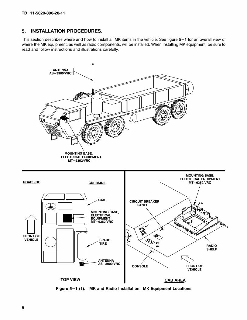
5.�INSTALLATION PROCEDURES.
This section describes where and how to install all MK items in the vehicle. See figure 5-1 for an overall view of
where the MK equipment, as well as radio components, will be installed. When installing MK equipment, be sure to
read and follow instructions and illustrations carefully.
Figure 5-1 (1).�MK and Radio Installation:�MK Equipment Locations
MOUNTING BASE,ELECTRICAL EQUIPMENT MT-6352/VRC
ANTENNAAS-3900/VRC
FRONT OFVEHICLE
ROADSIDE CURBSIDE
CAB
TOP VIEW
MOUNTING BASE,ELECTRICALEQUIPMENTMT-6352/VRC
ANTENNAAS-3900/VRC
SPARE TIRE
MOUNTING BASE,ELECTRICAL EQUIPMENT
MT-6352/VRC
CONSOLE
CAB AREA
CIRCUIT BREAKER PANEL
FRONT OFVEHICLE
RADIOSHELF
TB 11�5820�890�20�11
9
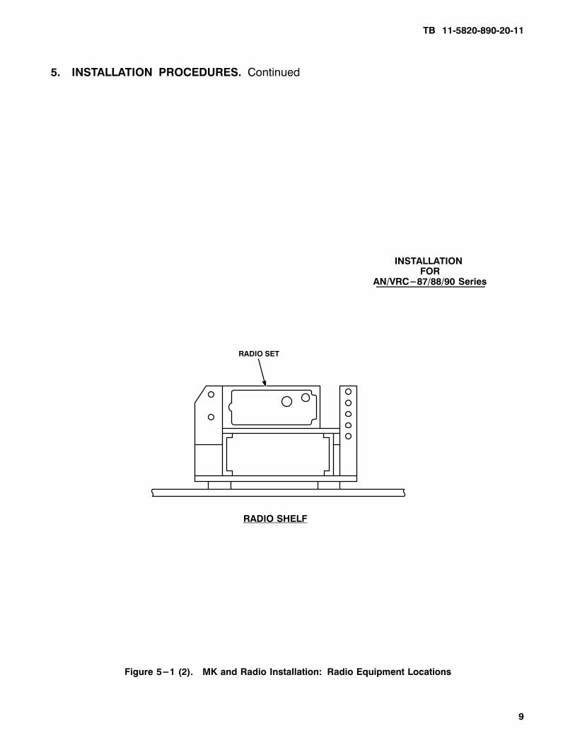
5.�INSTALLATION PROCEDURES.�Continued
Figure 5-1 (2).�MK and Radio Installation:�Radio Equipment Locations
RADIO SHELF
RADIO SET
INSTALLATION FOR
AN/VRC-87/88/90 Series
TB 11�5820�890�20�11
10
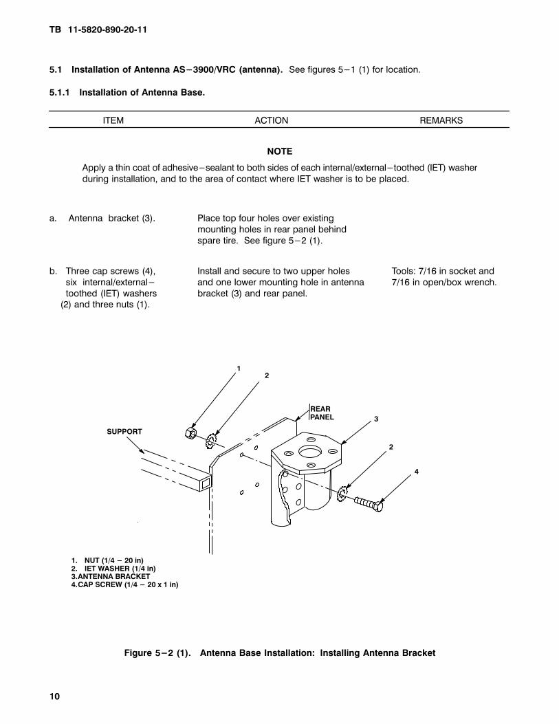
5.1�Installation of Antenna AS-3900/VRC (antenna). See figures 5-1 (1) for location.
5.1.1�Installation of Antenna Base.
ITEM ACTION REMARKS
NOTE
Apply a thin coat of adhesive-sealant to both sides of each internal/external-toothed (IET) washer
during installation, and to the area of contact where IET washer is to be placed.
a. Antenna bracket (3). Place top four holes over existing
mounting holes in rear panel behind
spare tire. See figure 5-2 (1).
b. Three cap screws (4), Install and secure to two upper holes Tools: 7/16 in socket and
six internal/external- and one lower mounting hole in antenna 7/16 in open/box wrench.
toothed (IET) washers bracket (3) and rear panel. (2) and three nuts (1).
1. NUT (1/4 - 20 in)2. IET WASHER (1/4 in)3.ANTENNA BRACKET4.CAP SCREW (1/4 - 20 x 1 in)
12
4
2
3
REAR PANEL
SUPPORT
Figure 5-2 (1).�Antenna Base Installation:�Installing Antenna Bracket
TB 11�5820�890�20�11
11
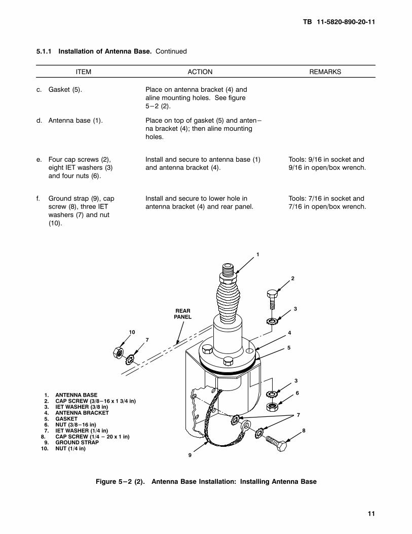
5.1.1�Installation of Antenna Base.�Continued
ITEM ACTION REMARKS
c. Gasket (5). Place on antenna bracket (4) and
aline mounting holes. See figure
5-2 (2).
d. Antenna base (1). Place on top of gasket (5) and anten-na bracket (4); then aline mounting
holes.
e. Four cap screws (2), Install and secure to antenna base (1) Tools: 9/16 in socket and eight IET washers (3) and antenna bracket (4). 9/16 in open/box wrench.
and four nuts (6).
f. Ground strap (9), cap Install and secure to lower hole in Tools: 7/16 in socket and screw (8), three IET antenna bracket (4) and rear panel. 7/16 in open/box wrench.
washers (7) and nut
(10).
7
10
9
1. ANTENNA BASE2. CAP SCREW (3/8-16 x 1 3/4 in)3. IET WASHER (3/8 in)4. ANTENNA BRACKET5. GASKET6. NUT (3/8-16 in)7. IET WASHER (1/4 in)
8. CAP SCREW (1/4 - 20 x 1 in)9. GROUND STRAP
10. NUT (1/4 in)
REAR PANEL
8
7
6
3
4
3
2
1
5
Figure 5-2 (2).�Antenna Base Installation:�Installing Antenna Base
TB 11�5820�890�20�11
12
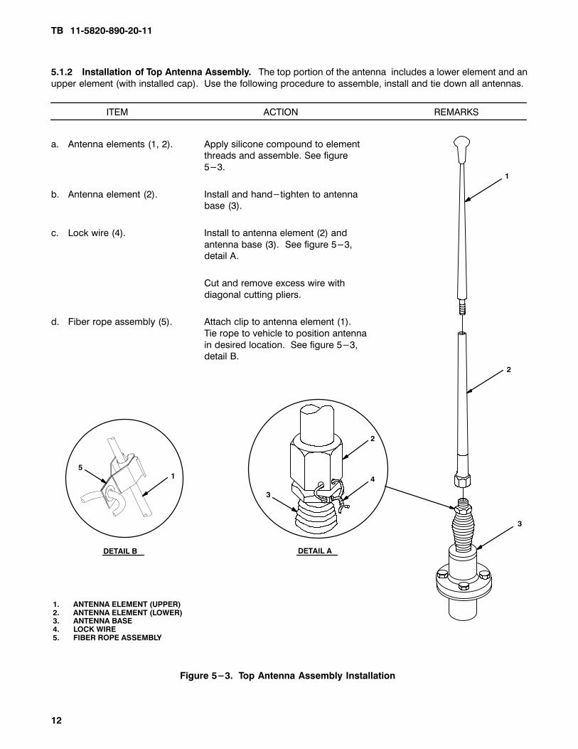
5.1.2�Installation of Top Antenna Assembly. The top portion of the antenna includes a lower element and an
upper element (with installed cap). Use the following procedure to assemble, install and tie down all antennas.
ITEM ACTION REMARKS
a. Antenna elements (1, 2). Apply silicone compound to element threads and assemble. See figure
5-3.
b. Antenna element (2). Install and hand-tighten to antenna base (3).
c. Lock wire (4). Install to antenna element (2) and
antenna base (3). See figure 5-3,detail A.
Cut and remove excess wire with
diagonal cutting pliers.
d. Fiber rope assembly (5). Attach clip to antenna element (1).
Tie rope to vehicle to position antenna
in desired location. See figure 5-3,detail B.
1
2
DETAIL B DETAIL A
4
Figure 5-3. Top Antenna Assembly Installation
2
51
1. ANTENNA ELEMENT (UPPER)2. ANTENNA ELEMENT (LOWER)3. ANTENNA BASE4. LOCK WIRE5. FIBER ROPE ASSEMBLY
3
3
TB 11-5820-890-20-11
13
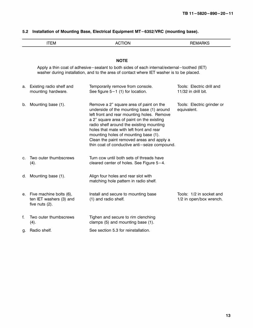
5.2 Installation of Mounting Base, Electrical Equipment MT-6352/VRC (mounting base).
ITEM ACTION REMARKS
NOTE
Apply a thin coat of adhesive-sealant to both sides of each internal/external-toothed (IET)washer during installation, and to the area of contact where IET washer is to be placed.
a. Existing radio shelf and Temporarily remove from console. Tools: Electric drill and
mounting hardware. See figure 5-1 (1) for location. 11/32 in drill bit.
b. Mounting base (1). Remove a 2" square area of paint on the Tools: Electric grinder or
underside of the mounting base (1) around equivalent.left front and rear mounting holes. Remove
a 2" square area of paint on the existing
radio shelf around the existing mountingholes that mate with left front and rear
mounting holes of mounting base (1).
Clean the paint removed areas and apply athin coat of conductive anti-seize compound.
c. Two outer thumbscrews Turn ccw until both sets of threads have(4). cleared center of holes. See Figure 5-4.
d. Mounting base (1). Align four holes and rear slot with matching hole pattern in radio shelf.
e. Five machine bolts (6), Install and secure to mounting base Tools: 1/2 in socket andten IET washers (3) and (1) and radio shelf. 1/2 in open/box wrench.
five nuts (2).
f. Two outer thumbscrews Tighen and secure to rim clenching
(4). clamps (5) and mounting base (1).
g. Radio shelf. See section 5.3 for reinstallation.
TB 11-5820-890-20-11
14
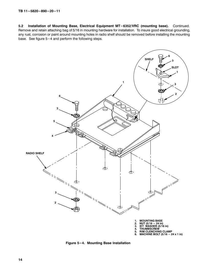
5.2 Installation of Mounting Base, Electrical Equipment MT-6352/VRC (mounting base). Continued.
Remove and retain attaching bag of 5/16 in mounting hardware for installation. To insure good electrical grounding,
any rust, corrosion or paint around mounting holes in radio shelf should be removed before installing the mounting
base. See figure 5-4 and perform the following steps.
2
RADIO SHELF
4
Figure 5-4. Mounting Base Installation
SLOT
5
3
1. MOUNTING BASE2. NUT (5/16 - 24 in)3. IET WASHER (5/16 in) 4. THUMBSCREW 5. RIM CLENCHING CLAMP6. MACHINE BOLT (5/16 - 24 x 1 in)
13
2
6
3
6
3
1
SHELF
TB 11-5820-890-20-11
15
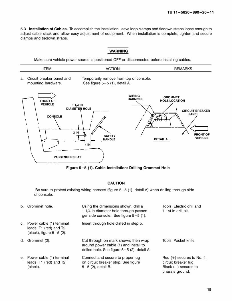
5.3 Installation of Cables. To accomplish the installation, leave loop clamps and tiedown straps loose enough to
adjust cable slack and allow easy adjustment of equipment. When installation is complete, tighten and secure
clamps and tiedown straps.
ITEM ACTION REMARKS
WARNING
Make sure vehicle power source is positioned OFF or disconnected before installing cables.
a. Circuit breaker panel and Temporarily remove from top of console.
mounting hardware. See figure 5-5 (1), detail A.
Figure 5-5 (1). Cable Installation: Drilling Grommet Hole
3 IN
4 IN
1 1/4 IN DIAMETER HOLE
SAFETY HANDLE
CONSOLE
PASSENGER SEAT
WIRING HARNESS
GROMMET HOLE LOCATION
CIRCUIT BREAKER PANEL
DETAIL A
FRONT OFVEHICLE
FRONT OFVEHICLE
CAUTION
Be sure to protect existing wiring harness (figure 5-5 (1), detail A) when drilling through side
of console.
b. Grommet hole. Using the dimensions shown, drill a Tools: Electric drill and 1 1/4 in diameter hole through passen- 1 1/4 in drill bit.
ger side console. See figure 5-5 (1).
c. Power cable (1) terminal Insert through hole drilled in step b.
leads: T1 (red) and T2
(black), figure 5-5 (2).
d. Grommet (2). Cut through on mark shown; then wrap Tools: Pocket knife. around power cable (1) and install to
drilled hole. See figure 5-5 (2), detail A.
e. Power cable (1) terminal Connect and secure to proper lug Red (+) secures to No. 4.
leads: T1 (red) and T2 on circuit breaker strip. See figure circuit breaker lug.(black). 5-5 (2), detail B. Black (-) secures to
chassis ground.
TB 11-5820-890-20-11
16
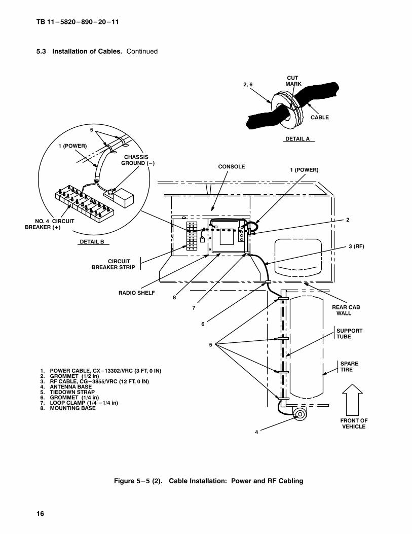
5.3 Installation of Cables. Continued
Figure 5-5 (2). Cable Installation: Power and RF Cabling
1. POWER CABLE, CX-13302/VRC (3 FT, 0 IN)2. GROMMET (1/2 in)3. RF CABLE, CG-3855/VRC (12 FT, 0 IN)4. ANTENNA BASE 5. TIEDOWN STRAP6. GROMMET (1/4 in)7. LOOP CLAMP (1/4 -1/4 in)8. MOUNTING BASE
DETAIL B
1 (POWER)
3 (RF)
2
4
5
2, 6
7
CIRCUIT BREAKER STRIP
5
1 (POWER)
SPARETIRE
SUPPORTTUBE
8
DETAIL A
CUTMARK
CHASSISGROUND (-)
CONSOLE
REAR CAB WALL
CABLE
FRONT OFVEHICLE
RADIO SHELF
6
NO. 4 CIRCUIT BREAKER (+)
TB 11-5820-890-20-11
17
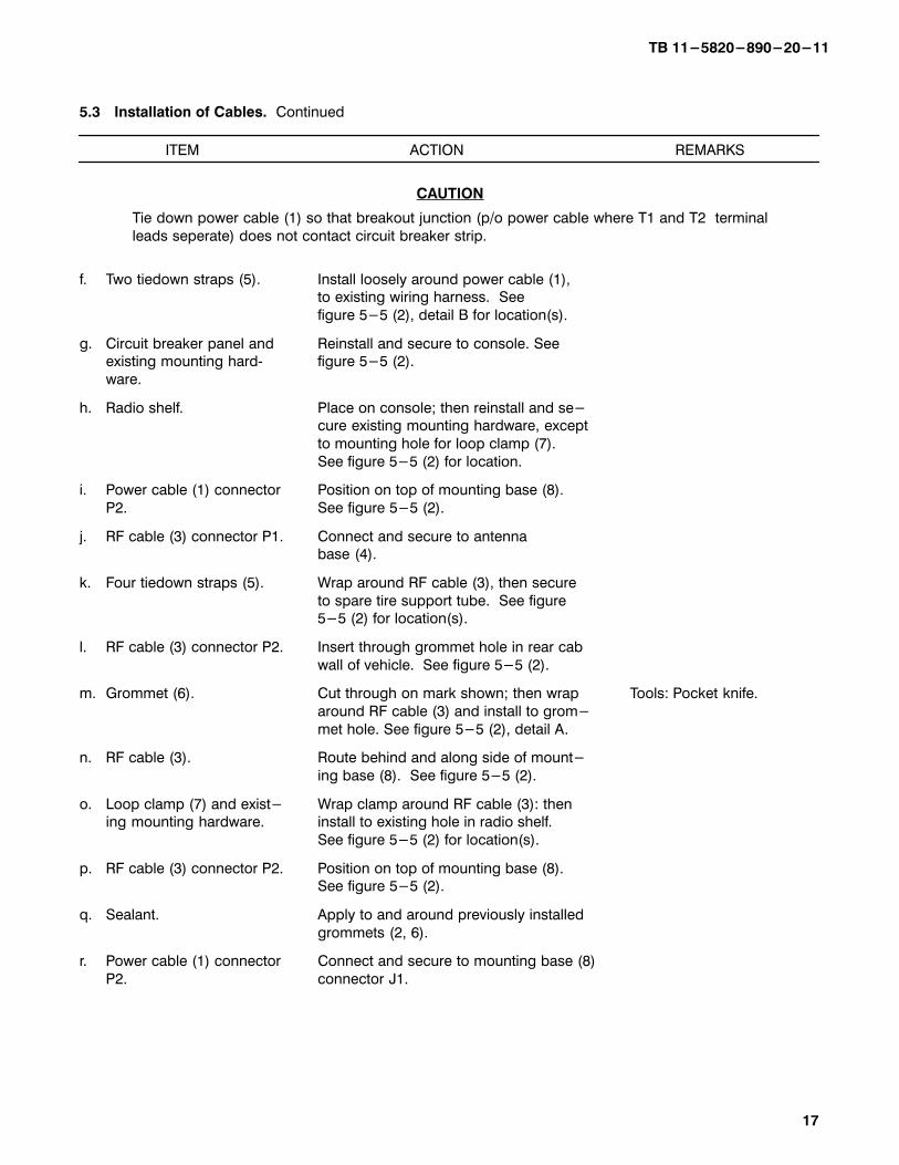
5.3 Installation of Cables. Continued
ITEM ACTION REMARKS
CAUTION
Tie down power cable (1) so that breakout junction (p/o power cable where T1 and T2 terminal
leads seperate) does not contact circuit breaker strip.
f. Two tiedown straps (5). Install loosely around power cable (1), to existing wiring harness. See
figure 5-5 (2), detail B for location(s).
g. Circuit breaker panel and Reinstall and secure to console. Seeexisting mounting hard� figure 5-5 (2).
ware.
h. Radio shelf. Place on console; then reinstall and se-cure existing mounting hardware, except
to mounting hole for loop clamp (7).
See figure 5-5 (2) for location.
i. Power cable (1) connector Position on top of mounting base (8).
P2. See figure 5-5 (2).
j. RF cable (3) connector P1. Connect and secure to antenna base (4).
k. Four tiedown straps (5). Wrap around RF cable (3), then secure
to spare tire support tube. See figure5-5 (2) for location(s).
l. RF cable (3) connector P2. Insert through grommet hole in rear cab
wall of vehicle. See figure 5-5 (2).
m. Grommet (6). Cut through on mark shown; then wrap Tools: Pocket knife.
around RF cable (3) and install to grom-
met hole. See figure 5-5 (2), detail A.
n. RF cable (3). Route behind and along side of mount-
ing base (8). See figure 5-5 (2).
o. Loop clamp (7) and exist- Wrap clamp around RF cable (3): thening mounting hardware. install to existing hole in radio shelf.
See figure 5-5 (2) for location(s).
p. RF cable (3) connector P2. Position on top of mounting base (8).See figure 5-5 (2).
q. Sealant. Apply to and around previously installed
grommets (2, 6).
r. Power cable (1) connector Connect and secure to mounting base (8)
P2. connector J1.
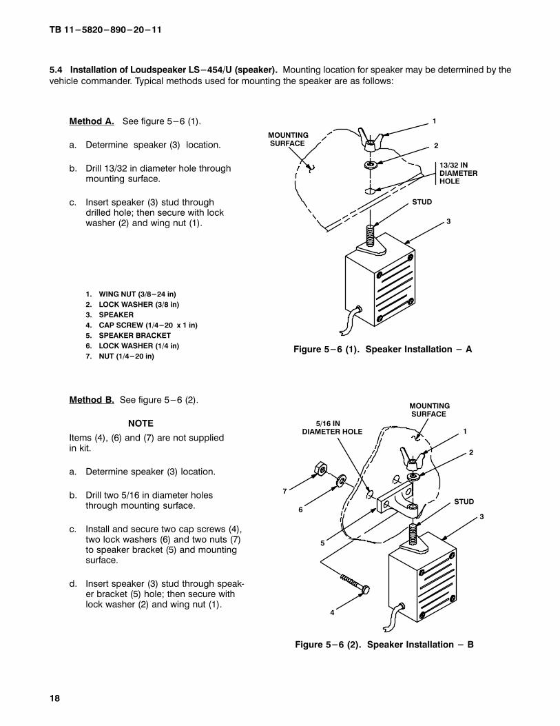
Figure 5-6 (1). Speaker Installation - A
1
2
3
MOUNTING SURFACE
13/32 INDIAMETERHOLE
STUD
Figure 5-6 (2). Speaker Installation - B
1
2
3
4
5
6
7
MOUNTING SURFACE
5/16 INDIAMETER HOLE
STUD
TB 11-5820-890-20-11
18
5.4 Installation of Loudspeaker LS-454/U (speaker). Mounting location for speaker may be determined by the
vehicle commander. Typical methods used for mounting the speaker are as follows:
Method A. See figure 5-6 (1).
a. Determine speaker (3) location.
b. Drill 13/32 in diameter hole throughmounting surface.
c. Insert speaker (3) stud throughdrilled hole; then secure with lock washer (2) and wing nut (1).
1. WING NUT (3/8-24 in)
2. LOCK WASHER (3/8 in)
3. SPEAKER
4. CAP SCREW (1/4-20 x 1 in)
5. SPEAKER BRACKET
6. LOCK WASHER (1/4 in)
7. NUT (1/4-20 in)
Method B. See figure 5-6 (2).
NOTE
Items (4), (6) and (7) are not supplied in kit.
a. Determine speaker (3) location.
b. Drill two 5/16 in diameter holes through mounting surface.
c. Install and secure two cap screws (4), two lock washers (6) and two nuts (7) to speaker bracket (5) and mounting surface.
d. Insert speaker (3) stud through speak�er bracket (5) hole; then secure withlock washer (2) and wing nut (1).
TB 11-5820-890-20-11
19/(22 blank)
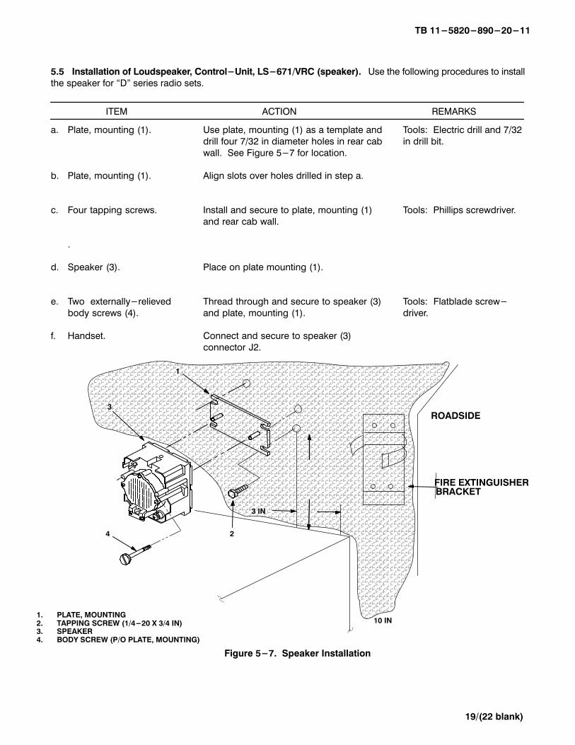
5.5 Installation of Loudspeaker, Control-Unit, LS-671/VRC (speaker). Use the following procedures to install
the speaker for �D" series radio sets.
ITEM ACTION REMARKS
a. Plate, mounting (1). Use plate, mounting (1) as a template and Tools: Electric drill and 7/32
drill four 7/32 in diameter holes in rear cab in drill bit.
wall. See Figure 5-7 for location.
b. Plate, mounting (1). Align slots over holes drilled in step a.
c. Four tapping screws. Install and secure to plate, mounting (1) Tools: Phillips screwdriver.
and rear cab wall.
.
d. Speaker (3). Place on plate mounting (1).
e. Two externally-relieved Thread through and secure to speaker (3) Tools: Flatblade screw-
body screws (4). and plate, mounting (1). driver.
f. Handset. Connect and secure to speaker (3)
connector J2.ÄÄÄÄÄÄÄÄÄÄÄÄÄÄÄÄÄÄÄÄÄÄÄÄÄÄÄÄÄÄÄÄÄÄÄÄÄÄÄÄÄÄÄÄÄÄÄÄÄÄÄÄÄÄÄÄÄÄÄÄÄÄÄÄÄÄÄÄÄÄÄÄÄÄÄÄÄÄÄÄÄÄÄÄÄÄÄÄÄÄÄÄÄÄÄÄÄÄÄÄÄÄÄÄÄÄÄÄÄÄÄÄÄÄÄÄÄÄÄÄÄÄÄÄÄÄÄÄÄÄÄÄÄÄÄÄÄÄÄÄÄÄÄÄÄÄÄÄÄÄÄÄÄÄÄÄÄÄÄÄÄÄÄÄÄÄÄÄÄÄÄÄÄÄÄÄÄÄÄÄÄÄÄÄÄÄÄÄÄÄÄÄÄÄÄÄÄÄÄÄÄÄÄÄÄÄÄÄÄÄÄÄÄÄÄÄÄÄÄÄÄÄÄÄÄÄÄÄÄÄÄÄÄÄÄÄÄÄÄÄÄÄÄÄÄÄÄÄÄÄÄÄÄÄÄÄÄÄÄÄÄÄÄÄÄÄÄÄÄÄÄÄÄÄÄÄÄÄÄÄÄÄÄÄÄÄÄÄÄÄÄÄÄÄÄÄÄÄÄÄÄÄÄÄÄÄÄÄÄÄÄÄÄÄÄÄÄÄÄÄÄÄÄÄÄÄÄÄÄÄÄÄÄÄÄÄÄÄÄÄÄÄÄÄÄÄÄÄÄÄÄÄÄÄÄÄÄÄÄÄÄÄÄÄÄÄÄÄÄÄÄÄÄÄÄÄÄÄÄÄÄÄÄÄÄÄÄÄÄÄÄÄÄÄÄÄÄÄÄÄÄÄÄÄÄÄÄÄÄÄÄÄÄÄÄÄÄÄÄÄÄÄÄÄÄÄÄÄÄÄÄÄÄÄÄÄÄÄÄÄÄÄÄÄÄÄÄÄÄÄÄÄÄÄÄÄÄÄÄÄÄÄÄÄÄÄÄÄÄÄÄÄÄÄÄÄÄÄÄÄÄÄÄÄÄÄÄÄÄÄÄÄÄÄÄÄÄÄÄÄÄÄÄÄÄÄÄÄÄÄÄÄÄÄÄÄÄÄÄÄÄÄÄÄÄÄÄÄÄÄÄÄÄÄÄÄÄÄÄÄ
3
4 2
1
1. PLATE, MOUNTING2. TAPPING SCREW (1/4-20 X 3/4 IN)3. SPEAKER4. BODY SCREW (P/O PLATE, MOUNTING)
Figure 5-7. Speaker Installation
3 IN
10 IN
ROADSIDE
FIRE EXTINGUISHERBRACKET
TB 11-5820-890-20-11
20
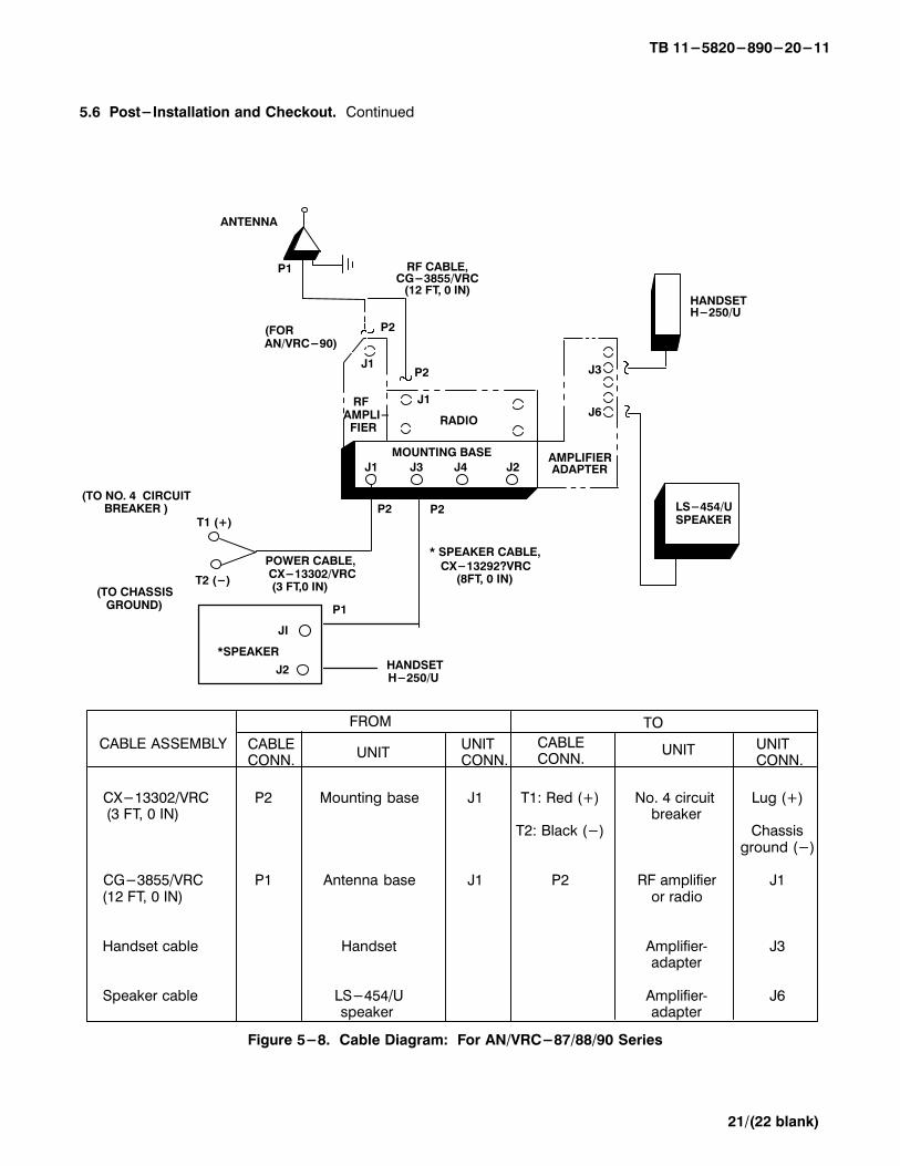
5.6 Post-Installation and Checkout. After equipment is installed and cables are connected, perform the
following steps.
ITEM ACTION REMARKS
a. Equipment. Check for secure mounting. Check
for loose parts, connectors and
mounting hardware.
b. Cables. Check for proper installation and
connection of cables. See figure
5-8 for cable connections. Unusedcables should be stowed in appropri-
ate place inside the vehicle.
c. Loop clamps. Check that all have been properlyinstalled and tightened.
d. Protective covers. Insure that all installed cables are
covered when not in use or con-nected.
e. Radio issued with vehicle. Install and connect cables. See
TM 11-5820-890-20-1 or TM 11-5820-890-20-2 for
installation and Operational (OP)
Check instructions.
f. MK line replaceable units. See TM 11-5820-890-20P for Repair
Parts and Special Tools List (RPSTL)
information.
TB 11-5820-890-20-11
21/(22 blank)
5.6 Post-Installation and Checkout. Continued
CX-13302/VRC P2 Mounting base J1 T1: Red (+) No. 4 circuit Lug (+) (3 FT, 0 IN) breaker
T2: Black (-) Chassisground (-)
CG-3855/VRC P1 Antenna base J1 P2 RF amplifier J1 (12 FT, 0 IN) or radio
Handset cable Handset Amplifier� J3 adapter
Speaker cable LS-454/U Amplifier� J6 speaker adapter
CABLE ASSEMBLY
FROM TO
CABLECONN.
UNITUNIT CONN.
CABLECONN.
UNIT UNIT CONN.
Figure 5-8. Cable Diagram: For AN/VRC-87/88/90 Series
T1 (+)
T2 (-)
(TO NO. 4 CIRCUIT BREAKER )
P1
J1
P2
P2
HANDSETH-250/U
ANTENNA
RF CABLE,CG-3855/VRC
(12 FT, 0 IN)
J1
P2
MOUNTING BASE
J2J4J3J1
RADIO
RFAMPLI- FIER
POWER CABLE, CX-13302/VRC (3 FT,0 IN)
LS-454/USPEAKER
(FOR AN/VRC-90)
J6
J3
AMPLIFIERADAPTER
(TO CHASSIS GROUND)
P2
* SPEAKER CABLE,
CX-13292?VRC(8FT, 0 IN)
JI
J2
*SPEAKERHANDSETH-250/U
P1
TB 11-5820-890-20-11
A-1/(A-2 blank)
APPENDIX A
REFERENCES
AMDF Army Master Data File (Microfiche)
AR 710-2 Supply Policy Below the Wholesale Level as Contained in Unit Supply UPDATE
AR 725-50 Requisitioning, Receipt and Issuing System in UPDATE
DA Pam 25-30 Consolidated Index of Army Publications (Microfiche)
DA Pam 710-2-1 Using Unit Supply System Manual Procedures as Contained in Unit Supply UPDATE
SB 11-131 Vehicular Radio Sets and Authorized Installations (SINCGARS)
TM 11-5820-890-10-1 Operator's Manual (ICOM Radio Sets)
TM 11-5820-890-10-3 Operator's Manual (Non-ICOM Radio Sets)
TM 11-5820-890-20-1 Unit Maintenance Manual (ICOM Radio Sets)
TM 11-5820-890-20-2 Unit Maintenance Manual (Non-ICOM Radio Sets)
TM 11-5820-890-20P Repair Parts and Special Tools List
By Order of the Secretary of the Army:
ERIC K. SHINSEKI General, United States Army Official: Chief of Staff
9920216
DISTRIBUTION:
To be distributed in accordance with the initial distribution number (IDN) 369557 requirementsfor TB 11-5820-890-20-11.
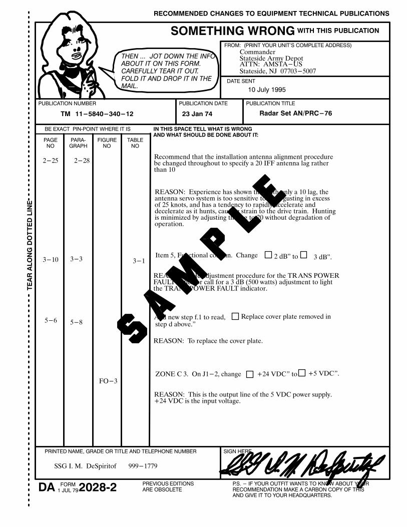
RECOMMENDED CHANGES TO EQUIPMENT TECHNICAL PUBLICATIONS
PREVIOUS EDITIONSARE OBSOLETE
P.S. - IF YOUR OUTFIT WANTS TO KNOW ABOUT YOURRECOMMENDATION MAKE A CARBON COPY OF THISAND GIVE IT TO YOUR HEADQUARTERS.
DA 2028�2FORM1 JUL 79
TE
AR
AL
ON
G D
OT
TE
D L
INE
BE EXACT PIN�POINT WHERE IT IS
SOMETHING WRONG
PUBLICATION NUMBER PUBLICATION DATE PUBLICATION TITLE
IN THIS SPACE TELL WHAT IS WRONG AND WHAT SHOULD BE DONE ABOUT IT:
DATE SENT
FROM: (PRINT YOUR UNIT'S COMPLETE ADDRESS)
WITH THIS PUBLICATION
THEN ... JOT DOWN THE INFO
ABOUT IT ON THIS FORM.
CAREFULLY TEAR IT OUT.
FOLD IT AND DROP IT IN THE
MAIL.
PRINTED NAME, GRADE OR TITLE AND TELEPHONE NUMBER SIGN HERE
PAGENO
PARA�GRAPH
FIGURENO
TABLENO
TM 11-5840-340-12 Radar Set AN/PRC-7623 Jan 74
2-25 2-28Recommend that the installation antenna alignment procedurebe changed throughout to specify a 20 IFF antenna lag ratherthan 10
REASON: Experience has shown that with only a 10 lag, theantenna servo system is too sensitive to wind gusting in excessof 25 knots, and has a tendency to rapidly accelerate and decelerate as it hunts, causing strain to the drive train. Huntingis minimized by adjusting the lag to 20 without degradation ofoperation.
3-10 3-3 3-1Item 5, Functional column. Change 2 dB" to 3 dB".
REASON: THe adjustment procedure for the TRANS POWERFAULT indicator call for a 3 dB (500 watts) adjustment to lightthe TRANS POWER FAULT indicator.
5-6 5-8Add new step f.1 to read, Replace cover plate removed in step d above."
REASON: To replace the cover plate.
FO-3ZONE C 3. On J1-2, change +24 VDC" to +5 VDC".
REASON: This is the output line of the 5 VDC power supply.+24 VDC is the input voltage.
SSG I. M. DeSpiritof 999-1779
CommanderStateside Army DepotATTN: AMSTA-USStateside, NJ 07703-5007
10 July 1995
RECOMMENDED CHANGES TO EQUIPMENT TECHNICAL PUBLICATIONS
PREVIOUS EDITIONSARE OBSOLETE
P.S. - IF YOUR OUTFIT WANTS TO KNOW ABOUT YOURRECOMMENDATION MAKE A CARBON COPY OF THISAND GIVE IT TO YOUR HEADQUARTERS.
DA 2028�2FORM1 JUL 79
TE
AR
AL
ON
G D
OT
TE
D L
INE
BE EXACT PIN�POINT WHERE IT IS
SOMETHING WRONG
PUBLICATION NUMBER PUBLICATION DATE PUBLICATION TITLE
IN THIS SPACE TELL WHAT IS WRONG AND WHAT SHOULD BE DONE ABOUT IT:
DATE SENT
FROM: (PRINT YOUR UNIT'S COMPLETE ADDRESS)
WITH THIS PUBLICATION
THEN ... JOT DOWN THE INFO
ABOUT IT ON THIS FORM.
CAREFULLY TEAR IT OUT.
FOLD IT AND DROP IT IN THE
MAIL.
PRINTED NAME, GRADE OR TITLE AND TELEPHONE NUMBER SIGN HERE
PAGENO
PARA�GRAPH
FIGURENO
TABLENO
TE
AR
AL
ON
G D
OT
TE
D L
INE
REVERSE OF DA FORM 2028-2
FOLD BACK
OFFICIAL BUSINESS
DEPARTMENT OF THE ARMY
FILL IN YOUR UNIT'S ADDRESS
Commander
U.S. Army Communications�Electronics Command
and Fort Monmouth
ATTN: AMSEL�LC�LEO�D-CS-CFO
Fort Monmouth, New Jersey 07703�5000
PLEASEAFFIX
STAMPPOSTAGEREQUIRED
FOLD BACK

071760-000

This fine document...
Was brought to you by me:
Liberated Manuals -- free army and government manuals
Why do I do it? I am tired of sleazy CD-ROM sellers, who take publicly available information, slap “watermarks” and other junk on it, and sell it. Those masters of search engine manipulation make sure that their sites that sell free information, come up first in search engines. They did not create it... They did not even scan it... Why should they get your money? Why are not letting you give those free manuals to your friends?
I am setting this document FREE. This document was made by the US Government and is NOT protected by Copyright. Feel free to share, republish, sell and so on.
I am not asking you for donations, fees or handouts. If you can, please provide a link to liberatedmanuals.com, so that free manuals come up first in search engines:
<A HREF=http://www.liberatedmanuals.com/>Free Military and Government Manuals</A>
– SincerelyIgor Chudovhttp://igor.chudov.com/