Embed Size (px)
Citation preview
TBM 1(86)
2015-12-08, Edition 7
TBM
TECHNICAL REGULATIONS
FOR
MECHANICAL EQUIPMENT
Edition 7, 2015-12-08
The Swedish Nuclear Power Companies have jointly produced this document.
Any revision of this document must be approved by mutual consultation
between the companies
Approved:
Anders Magnusson FKA, Erik Lindén OKG, Rasmus Waginder RAB
Licensee administrators of the PAKT-documents
TBM 2(86)
2015-12-08, Edition 7
LIST OF CONTENTS
1 INTRODUCTION ........................................................................................ 7 1.1 Background .............................................................................................. 7 1.2 Purpose and use ...................................................................................... 7 1.3 Content ...................................................................................................... 7
2 GENERAL PART ....................................................................................... 8 2.1 Field of Application .................................................................................. 8 2.2 Abbreviations, regulations and standards ............................................. 9 2.2.1 Definitions .................................................................................................. 9 2.2.2 Abbreviations .............................................................................................. 9 2.2.3 Regulations and standards ......................................................................... 9 2.3 Classification .......................................................................................... 10 2.3.1 Safety Class ............................................................................................. 10 2.3.2 Quality Classification ................................................................................ 11 2.4 Design specifications ............................................................................. 11 2.4.1 General .................................................................................................... 11 2.4.2 Contents ................................................................................................... 12 2.4.3 Guidelines ................................................................................................ 12 2.5 Design criteria ........................................................................................ 13 2.5.1 General .................................................................................................... 13 2.5.2 Objective and work sequence ................................................................... 14 2.5.3 Function requirements .............................................................................. 15 2.5.4 Modes of operation ................................................................................... 15 2.5.5 Loadings and combinations of loadings .................................................... 15 2.5.6 Acceptable Stresses ................................................................................. 16
3 MATERIAL, DESIGN AND MANUFACTURING AND INSTALLATION ... 18 3.1 Material .................................................................................................... 18 3.1.1 Metallic Materials ...................................................................................... 18 3.1.2 Silver ........................................................................................................ 19 3.1.3 Antimony .................................................................................................. 19 3.1.4 Aluminium and Zinc .................................................................................. 19 3.1.5 Carbon steel and low alloy steel ............................................................... 19 3.1.6 Martensitic and martensitic- austenitic steels ............................................ 19 3.1.7 Ferritic and ferritic-austenitic (duplex) stainless steel ................................ 19 3.1.8 Stainless steel castings ............................................................................ 20 3.1.9 Austenitic stainless steel .......................................................................... 20 3.1.10 Nickel based alloys type NiCrFe ............................................................... 20 3.1.11 Materials for salt water systems ................................................................ 21 3.1.12 Materials for intermediate drainage .......................................................... 21 3.1.13 Materials for bolts, nuts and washers ....................................................... 21 3.1.14 Filler materials for welding ........................................................................ 22 3.1.15 Plastic and rubber .................................................................................... 23 3.1.16 Gasket material ........................................................................................ 23 3.1.17 Lubricants ................................................................................................. 24 3.1.18 Thermal insulation .................................................................................... 24 3.2 Design and calculation........................................................................... 24 3.3 Manufacturing and installation .............................................................. 25 3.3.1 Standards for welding ............................................................................... 25 3.3.2 Heat affected zone ................................................................................... 25 3.3.3 Requirements for temporary welds ........................................................... 26 3.3.4 Requirements for handling of stainless steels and nickel-based alloys ..... 26 3.3.5 Welding .................................................................................................... 27 3.3.6 Fit up and tack welding ............................................................................. 27 3.3.7 Weld procedure / welding data sheets (WPS) ........................................... 28 3.3.8 Certain requirements for weld joints ......................................................... 28
TBM 3(86)
2015-12-08, Edition 7
3.3.9 Repair Welding of base material ............................................................... 29 3.3.10 Repairs of welds ....................................................................................... 29 3.3.11 Forming and straightening ........................................................................ 30 3.3.12 Heat treatment .......................................................................................... 31 3.3.13 Marking .................................................................................................... 32 3.4 Surface treatment ................................................................................... 34 3.4.1 General .................................................................................................... 34 3.4.2 Painting-, Corrosivity- and Environment classes ....................................... 34 3.4.3 Design and pre-treatment ......................................................................... 35 3.4.4 Painting .................................................................................................... 36 3.4.5 Galvanizing .............................................................................................. 37 3.4.6 Rubber lining ............................................................................................ 37 3.4.7 Storage and Transport .............................................................................. 38 3.5 Documentation ....................................................................................... 38 3.5.1 Necessary Documentation at Tender ....................................................... 38 3.5.2 Documentation required prior to manufacturing ........................................ 38 3.5.3 Documentation of deviations during manufacturing .................................. 39 3.5.4 Delivery of Technical Documentation ....................................................... 39 3.5.5 Documentation of surface treatment ......................................................... 39
4 EQUIPMENT SPECIFIC REGULATIONS ................................................ 40 4.1 Piping ...................................................................................................... 40 4.1.1 General .................................................................................................... 40 4.1.2 Weld joints ................................................................................................ 40 4.1.3 Design of seals in flanged connections ..................................................... 45 4.1.4 Threaded connections .............................................................................. 45 4.2 Pipe fittings ............................................................................................. 45 4.2.1 Branch connections .................................................................................. 45 4.2.2 Elbows and bent pipes ............................................................................. 47 4.2.3 Reducers .................................................................................................. 48 4.2.4 Flanged connections ................................................................................ 48 4.2.5 Caps in pipe system ................................................................................. 49 4.2.6 Welded lugs on steel pipes ....................................................................... 49 4.2.7 Other pipe fittings ..................................................................................... 51 4.3 Valves ...................................................................................................... 51 4.3.1 Introduction .............................................................................................. 51 4.3.2 Material restrictions .................................................................................. 51 4.3.3 Design and calculation ............................................................................. 52 4.3.4 Manufacturing ........................................................................................... 56 4.3.5 Documentation ......................................................................................... 57 4.4 Pumps ..................................................................................................... 59 4.4.1 Introduction .............................................................................................. 59 4.4.2 Material restrictions .................................................................................. 59 4.4.3 Design and calculation ............................................................................. 60 4.4.4 Vibrations and balancing .......................................................................... 61 4.4.5 Manufacturing ........................................................................................... 62 4.4.6 Documentation ......................................................................................... 62 4.5 Heat Exchangers .................................................................................... 65 4.5.1 Introduction .............................................................................................. 65 4.5.2 Material restrictions .................................................................................. 65 4.5.3 Design and Calculations ........................................................................... 65 4.5.4 Manufacturing ........................................................................................... 67 4.5.5 Documentation ......................................................................................... 68 4.6 Process Measuring Equipment ............................................................. 70 4.6.1 Introduction .............................................................................................. 70 4.6.2 Design requirements on certain components ............................................ 70 4.7 Pressure vessels .................................................................................... 71 4.7.1 Introduction .............................................................................................. 71
TBM 4(86)
2015-12-08, Edition 7
4.7.2 Design ...................................................................................................... 71 4.7.3 Connections ............................................................................................. 71 4.7.4 Sealing arrangements .............................................................................. 72 4.7.5 Strength calculations ................................................................................ 72 4.7.6 Documentation ......................................................................................... 72 4.8 Supports ................................................................................................. 74 4.8.1 Introduction .............................................................................................. 74 4.8.2 Material restrictions .................................................................................. 74 4.8.3 Design and Calculations ........................................................................... 74 4.8.4 Manufacturing ........................................................................................... 77 4.8.5 Documentation ......................................................................................... 77 4.9 Atmospheric storage tanks ................................................................... 79 4.9.1 Design ...................................................................................................... 79 4.9.2 Calculation ............................................................................................... 79 4.9.3 Manufacturing ........................................................................................... 80 4.9.4 Documentation ......................................................................................... 80 4.10 Internals for reactor pressure vessels and steam generators ............ 82 4.10.1 Restrictions for material in reactor internal parts ....................................... 82 4.10.2 Design ...................................................................................................... 82 4.10.3 Documentation and delivery ..................................................................... 82 4.11 Pipe rupture restraints ........................................................................... 83 4.11.1 Introduction .............................................................................................. 83 4.11.2 Material .................................................................................................... 83 4.11.3 Design ...................................................................................................... 83 4.11.4 Calculation ............................................................................................... 84 4.11.5 Manufacturing ........................................................................................... 84 4.11.6 Documentation ......................................................................................... 85
5 REPAIR OF INSTALLED EQUIPMENT ................................................... 86
TBM 5(86)
2015-12-08, Edition 7
ATTACHMENTS
Appendix 1 “EVENT CATEGORIZATION“ ANSI/ANS-52.1-1983
Appendix 2 TABLE 3-6 in ANSI/ANS-52.1-1983
Appendix 3 Oxide reference
Appendix 4 Tightness classification
Attachments associated with TBM:
Appendix 5 TSM Specifications
Piping, E-TSM 101
Valve, E-TSM 102
Control valve, E-TSM 103
Safety valve, E-TSM 104
Pump, E-TSM 106
Heat exchanger, E-TSM 107
TBM 6(86)
2015-12-08, Edition 7
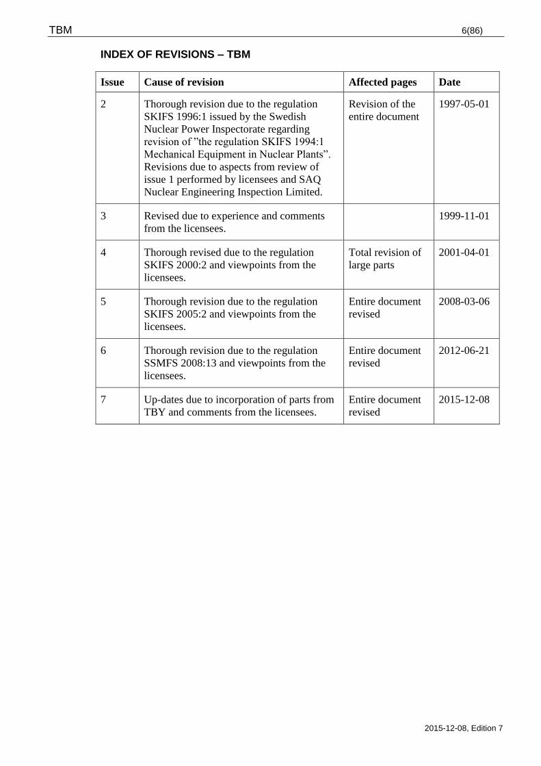
INDEX OF REVISIONS – TBM
Issue Cause of revision Affected pages Date
2 Thorough revision due to the regulation
SKIFS 1996:1 issued by the Swedish
Nuclear Power Inspectorate regarding
revision of ”the regulation SKIFS 1994:1
Mechanical Equipment in Nuclear Plants”.
Revisions due to aspects from review of
issue 1 performed by licensees and SAQ
Nuclear Engineering Inspection Limited.
Revision of the
entire document
1997-05-01
3 Revised due to experience and comments
from the licensees.
1999-11-01
4 Thorough revised due to the regulation
SKIFS 2000:2 and viewpoints from the
licensees.
Total revision of
large parts
2001-04-01
5 Thorough revision due to the regulation
SKIFS 2005:2 and viewpoints from the
licensees.
Entire document
revised
2008-03-06
6 Thorough revision due to the regulation
SSMFS 2008:13 and viewpoints from the
licensees.
Entire document
revised
2012-06-21
7 Up-dates due to incorporation of parts from
TBY and comments from the licensees.
Entire document
revised
2015-12-08
TBM 7(86)
2015-12-08, Edition 7
1 INTRODUCTION
1.1 Background
TBM “Technical Regulations for Mechanical Equipment” is a jointly prepared
implementation document by the Swedish Nuclear Power utilities and constitutes a
common interpretation aimed to fulfil.
The SSM (The Swedish Radiation Safety Authority) requirements from the issued
regulations SSMFS 2008:13
The design and manufacturing requirements issued by The Swedish Work Environment
Authority, applying to for pressurised equipment AFS 1999:4, AFS 1993:41, (revised in
AFS 1994:53) and AFS 2005:2
The licenses own requirements
The regulations may also be used as guidance, for equipment and work that is not covered
by stated area of application.
TBM and other PAKT-documents shall be revised frequently. New rules and gained
experiences shall be implemented in the documents upon revision.
1.2 Purpose and use
The purpose of these technical requirements, TBM, are to clarify and interpret the
requirements for new and modified mechanical equipment to be installed in Swedish
nuclear plants. Requirements in addition to TBM requirements shall be specified in the
equipment specification of the respective equipment.
TBM does not apply to requirements related to system- or plant level, for instance
redundancy or diversification.
TBM shall be used together with the common power plant quality regulations KBM.
When mechanical equipment covered by TBM also includes electrical parts, the TBE and
KBE shall be used together with TBM and KBM.
The licensees shall use TBM at purchasing, design, manufacturing, repair and installation
of mechanical equipment.
1.3 Content
Chapter 1 describes background, purpose, usage and content of TBM.
Chapter 2 describes field of application for TBM, provides definitions, describes the
classification procedure in Swedish nuclear power plants and gives guidance at preparation
of design criteria for mechanical integrity.
Chapter 3 describes general requirements and regulations for material, surface treatment,
design, manufacture and installation of mechanical equipment.
Chapter 4 describes object specific requirements and regulations to be reported for different
types of mechanical equipment which means additions and exemptions from the general
requirements and regulations specified in chapter 3
Chapter 5 describes requirements at repair of installed equipment.
TBM 8(86)
2015-12-08, Edition 7
Chapter 1, 2 and 5 are normally intended for the licensee, while applicable parts of chapter
3 - 4 normally is included in the documentation, which is be sent to a supplier.
2 GENERAL PART
2.1 Field of Application
The nuclear plants covered by these regulations are:
Forsmark 1, 2 and 3
Oskarshamn 1, 2 and 3
Ringhals 1, 2, 3 and 4
The technical regulations applies to repairs, exchanges and plant modifications / additions
for such mechanical equipment covered by the following:
Mechanical equipment that are part of the primary system or within the containment
barrier or in safety, process and auxiliary systems in the nuclear power plant.
Mechanical equipment with significance for safe plant operation and is affected by the
requirement for staff protection against illness and accidents.
Mechanical equipment with significance for the plant’s production capability and
availability.
The technical requirements does however not apply to:
Moving machine parts in turbines, motors and generators,
Lifting equipment and lifting tools,
Mechanical parts in nuclear fuel bundles,
Containers used for transportation of nuclear substance and nuclear waste,
Mechanical equipment used for handling, processing, storage or final disposal of nuclear
waste and containers intended for use with nuclear waste.
In applicable parts, TBM can be used as guidance for repairs, exchanges, modifications and
additions to mechanical equipment such as moving and internal machine parts in pumps,
valves, turbines and generators.
The technical requirements are neither applicable to:
Such atmospheric storage tank intended for flammable liquid for which regulations have
been issued in accordance with the statute (2010:1075) concerning flammable and
explosive material.
Such piping for inflammable liquid for which regulations have been issued in accordance
with the statute concerning flammable material, and which is used between a vessel that
is not pressure vessel or vacuum vessel.
The technical regulations can in applicable parts be used as guidance for repairs, exchanges,
modifications and additions of atmospheric storage tanks and piping for flammable liquid.
TBM 9(86)
2015-12-08, Edition 7
2.2 Abbreviations, regulations and standards
2.2.1 Definitions
For definitions se the licensees common definition, PAKT list of definitions.
2.2.2 Abbreviations
AFS Swedish Work Environment Authority - Code of Statutes
ANSI American National Standard Institute
ANS American Nuclear Society
ASME American Society of Mechanical Engineers
ASTM American Society for Testing and Materials
BWR Boiling Water Reactor
CFR Code of Federal Regulations
DIN Deutsches Institut für Normung
DN Nominal Diameter (see Nominal Pipe Size NPS and SS-EN ISO 6708
EN European Standard
GDC General Design Criteria
HAZ Heat Affected Zone
ISA International Society of Automation
ISO International Organization for Standardization
KBE Quality Regulations for Electrical Equipment
KBM Quality Regulations for Mechanical Equipment
KFM Design Criteria for Mechanical Equipment
PED Pressure Equipment Directive
PWR Pressurized Water Reactor
RCPB Design Criteria for Mechanical Equipment
SAR Safety Analysis Report
SS Swedish Standard
SSM Swedish Radiation Safety Authority
SSMFS Regulations by the Swedish Radiation Safety Authority
TBE Technical Regulations for Electrical Equipment
TBM Technical Regulations for Mechanical Equipment
TBV Technical regulations for Ventilation Equipment
TBY Technical Regulations for Corrosion Protection
TSM Technical Specifications for Mechanical Equipment
VDI/VDE Verein Deutscher Ingenieure/Verband der Elektrotechnik
WPQR Welding Procedure Qualification Record (Protocol for welding procedure
qualification)
WPS Welding Procedure Specification (Welding Data Sheet)
2.2.3 Regulations and standards
Unless specific edition of standard is specified the latest issue, alternatively new standard
replacing the obsolete to be used. However, the licensee shall approve new standards.
TBM 10(86)
2015-12-08, Edition 7
The below specified regulations, codes and standards shall be applied unless otherwise
specified in the purchase order.
Swedish regulations
AFS 1994:4 Pressure retaining equipment
AFS 1993:41 Simple pressure vessels
SSMFS 2008:13 The Radiation Safety Authority’s regulation for mechanical
equipment in certain nuclear plants
Swedish standards:
SS-EN 13445
SS-EN 13480
Pressure vessels
Pipe lines
SS-EN 1993-4-2 Atmospheric storage tanks
Foreign Standards
ANSI/ANS-51.1-1983 ANSI/ANS nuclear safety criteria for the design of stationary
pressurized water reactor plants
ANSI/ANS-52.1-1983 ANSI/ANS nuclear safety criteria for the design of stationary
boiling water reactor plants
ASME III ASME BPVC Section III – Rules for Construction of Nuclear
Facility Components
ASME VIII ASME BPVC Section VIII – Rules for Construction of Pressure
Vessels
EKS European Design Standards
2.3 Classification
All equipment in a nuclear power plant is divided into safety classes based upon the
importance of the equipment from the nuclear power safety point of view. By tradition this
divisioning is based on American regulations and codes, i.e. in this case 10CFR50,
Appendix A, GDC 1. According to this regulation shall the design of structures, systems
and components be of a quality corresponding to the importance of the actual functions
from safety point of view.
2.3.1 Safety Class
The division into safety classes is based upon the risk of radioactive discharge to the
external environment. Safety class 1 denotes the highest requirements and safety class 4 is
equivalent to “conventional requirements”. The division is performed as per the provisions
of the code ANS-52.1 edition 1983 for BWR plants and ANSI/ANS 51.1 edition 1983 for
PWR plants.
The safety classification governs the division into classes of mechanical and electrical
equipment. For mechanical equipment, the safety classification governs the quality
TBM 11(86)
2015-12-08, Edition 7
classification and for the electrical equipment it governs the electrical function
classification.
2.3.2 Quality Classification
Mechanical equipment shall be divided into five quality classes (1-4, 4A). The main rule is
that a piece of equipment is assigned the same quality class as the safety class. The quality
class governs the design, manufacturing, installation and inspection requirements and the
quality assurance measures at plant modifications and additions, replacements and repairs
in the plant.
Equipment classified as NNS (Non Nuclear Safety) according to ANSI/ANS 51.1 or 52.1 is
either assigned quality class 4A or 4, quality class 4A applies to equipment that can contain
large amounts of radioactive substances.
Mechanical equipment that is not covered by SSMFS 2008:13 (conventional equipment)
are not assigned quality class 1-4 (or 4A).
The principles for the division into quality classes shall be safety reviewed according to
SSMFS 2008:1, 4 chapter 3§. Prior to applying these principles, they shall be reported to
The Swedish Radiation Safety Authority.
The division in quality classes is evident from the current flow charts for the respective
plant and / or by classification lists, based on classification rules part of the safety analysis
report (SAR) for the respective plant. Valid rules and principles for quality classification is
reported to and accepted by the SSM for the respective plant. At plant modifications where new systems or system parts are added, these are classified
according to rules and principles in the safety analysis report (SAR for the respective plant.
2.4 Design specifications
2.4.1 General
The purpose of this chapter is to give guidance at preparation of design specifications. The
licensee is responsible for establishing the design specifications.
The design specifications specifies the requirements that shall be fulfilled for the
equipment, they shall also list the conditions for the mechanical detailed design plus satisfy
the authority requirements to describe the extent of the modification to the detailed
necessary to enable a review.
The design specifications shall have been subjected to a safety review according to chapter
4 §3 of SSMFS 2008:1 and the included design criteria shall be reported to SSM prior to
applying the design specifications.
Design specifications shall be prepared at all modifications of mechanical equipment in the
plant that may cause changed conditions for any part of the plant, this applies to all quality
classes. Such modifications of mechanical equipment, which are included in the
requirement of design specifications, are:
plant modifications and additions
such exchanges where the load condition of the system part in question may be affected
by the function or design of the replacement equipment
exchanges that affect more than a limited part of a system
TBM 12(86)
2015-12-08, Edition 7
measures that are taken to remove cracks or corrosion attacks without any subsequent
repair of parent material or weld deposit.
2.4.2 Contents
Design specifications shall be prepared in accordance with guidelines specified in SSMFS
2008:13 and to applicable extent contain the following data:
requirements for the function of the equipment
boundary to other equipment including the loadings at the boundary
mechanical design criteria (KFM)
requirements for protection of over pressurization
internal and external environment including possible neutron radiation
requirements for inspection and testing capability
classification (safety-, quality, seismic-, tightness-, electrical function-)
specific material requirements
listing of codes and standards governing the design, issue to be specified
list of valves and interlocks that at operation must be locked in open or closed position
reference to documents describing criteria for readiness for operation
listing of active components (components where a mechanical movement is required to
perform the nuclear safety function of the component)
flow charts
The design specification should also contain analyses of the modification’s affect on the
loadings and operation limits of existing equipment in the actual system as well as in
connecting systems.
2.4.3 Guidelines
At preparation of design specifications it is essential that the SAR in force is taken into
consideration since it provides the background that is required, this to avoid that the
requirement for the intended modification will be in conflict with the general plant
requirements. Each respective licensee got internal procedures for preparation of a design
specification.
2.4.3.1 Interfaces
For all interfaces to the existing systems (-parts), requirements shall be raised to specify all
occurring forces, torques and displacements, alternatively this information shall be attached
to enable the determination of the interaction of the interfaces during the design work.
2.4.3.2 Design criteria
Guidelines to design criteria are found in TBM chapter 2.5. Normally there is a reference in
the design specification to separate mechanical design criteria (KFM).
TBM 13(86)
2015-12-08, Edition 7
2.4.3.3 Manufacture
If certain manufacturing process requirements are raised as per TBM chapter 3.3 this has to
be evident from the design specification.
2.4.3.4 Testing
If pressure test shall be performed by air or gas instead of liquid this must be required by
the design specification.
Possible limitations for the selection of liquid for the testing shall be specified. At selecting
liquid it must be regarded that the liquid has no negative impact and that it may be used for
the pressure and temperature in question.
It must also be stated if certain requirements apply at pressure test of expansion bellows.
Tightness requirements for stem seals, valve seats, flanged connections, etc. shall be
included in the design specification.
2.4.3.5 Protection against over pressurization
Such components where pressure and associated temperature, either static or in connection
with transients, may exceed design data must be protected against over pressurization. In
the design specification it must be stated if there is requirement for protection against over
pressurization and, if this is the case data of required blow-down capacity to be specified.
2.4.3.6 Certain component requirements
If there are certain requirements for any component according to TBM chapter 4 this has to
be evident from the design specification.
2.5 Design criteria
2.5.1 General
The mechanical design criteria (KFM) constitute a description of the significant loadings
and combination of loadings with acceptance criteria for a unique system configuration e.g.
a piping system including supports. A KFM shall contain sufficient data to perform a
verification of structural integrity.
Each plant shall have a procedure which always shall be applied at the preparation and
update of KFM for mechanical equipment. In case of deviations between this chapter for
design criteria and the plant specific KFM procedure, the plant specific KFM to be
governing and applied.
The below text is a coarse overview of preparation of a KFM with regard to mechanical
integrity of mechanical equipment. The requirements for mechanical integrity are based on
codes aiming to the resistance of pressure retaining and load bearing equipment to pressures
and other loadings without breaks or leaks. The quality class for the respective equipment
TBM 14(86)
2015-12-08, Edition 7
governs the codes to be applied at analysis of the mechanical integrity. Also function
requirements on active and passive component affects the evaluation.
SSMFS 2008:13 has been governing for the guidelines in this subsection, where it in
chapter 4. §4 reads:
At modifications in a plant that affects mechanical equipment through:
modifications and additions
such replacements where the relevant loading conditions of the actual system part may
be affected by the function or design of the replacement parts
replacements that affects more than a limited part of a system
measures according to § 2.
The design and performance to be based upon current design specifications that shall be
safety reviewed according to chapter 4, §3 in SSMFS 2008:1.
Prior to applying the design specifications, the design criteria therein to be reported to The
Swedish Radiation Safety Authority.
In the General Recommendations concerning the application of SSMFS 2008:13 there are
several references made to ASME III.
Even though the references to ASME III are just advisory, the choice is made to follow the
main part of the arrangement prescribed by ASME III NCA-2140, section Design Basis,
appendix B at preparation of design criteria for mechanical integrity. The reason for this is
the tradition to follow ASME III at qualified evaluations.
In cases when the evaluation shall be performed according to a different code, the work
sequence according to ASME is still to be applied at preparation of design criteria for
mechanical integrity.
2.5.2 Objective and work sequence
The following objective and work sequence can be established from an interpretation of
applicable parts of SSMFS 2008:13 and ASME III.
The design criteria for mechanical integrity shall specify the applicable loadings and
loading combinations that mechanical equipment is subjected to. In addition data regarding
permissible stresses to be included.
At the preparation the following procedure should be applied:
Determine the functional requirements
Determination of applicable modes of operation, upset conditions and accidents
Establishment of loads and load combinations
Determination of acceptable stresses
The design criteria for the mechanical integrity in quality class 1, 2, 3, 4 and 4A shall
specify the entire scope of design loading, operation loading and corresponding, acceptable
stresses. There is no regulation requirement to prepare design criteria for mechanical
equipment which got no quality class.
TBM 15(86)
2015-12-08, Edition 7
2.5.3 Function requirements
At identification of the loads on a system there is a review performed of available
documentation such as SAR, system descriptions, classification lists, flow charts, operation
reports, operation procedures, accident procedures, transient documentation, analyses of
protection for over pressurisation, reportable incidents, global experiences, SSM-decisions
etc. All these documents provide data related to the function of the system and operation,
and function requirements and different events.
2.5.4 Modes of operation
In order to determine the loads a piece of equipment is subjected to the different operation
modes loads affecting the component have to be determined. This includes the normal
conditions, upset and accidents the piece of equipment shall withstand. In addition, to
evaluate the limits to be set for the different loads it is necessary to anticipate a probability
for each mode of operation (lower probability for an operating condition leads to
acceptance of higher threshold values, see chapter 2.5.6).
A method to describe this is to divide the modes of operation in different event classes. The
event classes H1-H5 and residual risks are defined in SSMFS 2008:17. In ANSI/ANS 51.1
(PWR) and ANSI/ANS 52.1 (BWR) a set of event classes named “Plant Conditions“ (PC)
are defined. Briefly, one can say that H1 and PC1 corresponds to normal operating
situations while higher designations specify disturbances or accident situations with a
decreasing degree of probability.
A summary of probabilities for different H and PC and a connection to other applied event
classes is specified in Appendix 1.
The applicable event classification shall be described in the safety analysis report for the
respective plant. If this is missing the relevant modes of operation must be established for
affected system, this based upon event analyses from the current safety analysis report.
Through evaluation of this can relevant modes of operation be established on system- and
equipment level.
Example of this is:
normal operation (pressure, temperature, dead weight)
pump transients (start/stop)
valve manoeuvring
temperature transients
vibrations (e.g. due to pipe break or pool dynamics)
seismic event
Each case of operation mode shall then be related to relevant plant condition or be assigned
an evaluated probability.
2.5.5 Loadings and combinations of loadings
Loadings are divided into Design Loadings, Service Loadings and Test Loadings. ASME
III Appendix B-2121 lists the loadings to be considered.
At evaluation the simultaneously acting loads to be lumped together. This often means that
a dynamic loading is regarded together with internal pressure and dead weight.
TBM 16(86)
2015-12-08, Edition 7
2.5.5.1 Design Loadings
Design Loadings are in turn divided into design pressure, design temperature and
mechanical design loadings. The loadings for which the component shall be strength
calculated, shall be included in these (cyclic or transient loading are normally not included),
see ASME III section NCA-2142.1 "Design Loadings".
2.5.5.2 Service Loadings
The service loading shall be derived from the anticipated operation modes. All the loadings
the component is subjected to, during predictable, normal and upset service situations and
possible accident situations are related to service loading. To service loading belongs
pressure, temperature, mechanical loads and their possible cyclic or transient course (see
further ASME III section NCA 2142.2 “Service Loading“). Related service loadings are
combined to load combinations (Service Loading Combinations) which together with
adherent event classes and anticipated probability shall be evaluated against relevant
service limit, see below.
2.5.5.3 Test Loadings
The loadings that occur at different tests of a system or a piece of equipment belongs to test
loadings. Analyses of loadings at pressure test are performed if the test is regarded as being
carried out at different system characteristics than those covered by design loadings for
example pressure test with water filled piping and blocked hangers for steam piping, or at
high test pressures. Loadings from other types of tests are regarded similar to service
loadings, see further ASME III section NCA-2142.3 "Test Loadings".
2.5.6 Acceptable Stresses
Acceptable stresses are divided in Design Limits, Service Limits and Test Limits (see
ASME III section NCA-2142.4 "Design, Service and Test Limits").
2.5.6.1 Design Limits
Design limits specify the limit for the design loading. In case service loadings are not to be
evaluated, the design limit is set to the same level as Service Limits A (see below).
Otherwise the design limits are evident from the evaluation instructions available in e.g.
ASME III (sections NB, NC, ND, NE, NF or NG) or SS-EN 13480 and SS-EN 13445.
2.5.6.2 Service Limits
The service limits are divided into four levels according to ASME III, Service Limits A, B,
C and D. Limit A corresponds to limits stating the margins and safety factors needed for the
component to satisfy its specified performance.
Limit B corresponds to the limits giving smaller margins and safety factors compared to
Limit A, but where still no damage to the component will arise. Limits C and D correspond
to limits giving further reduction of margins and safety factors and where permanent
TBM 17(86)
2015-12-08, Edition 7
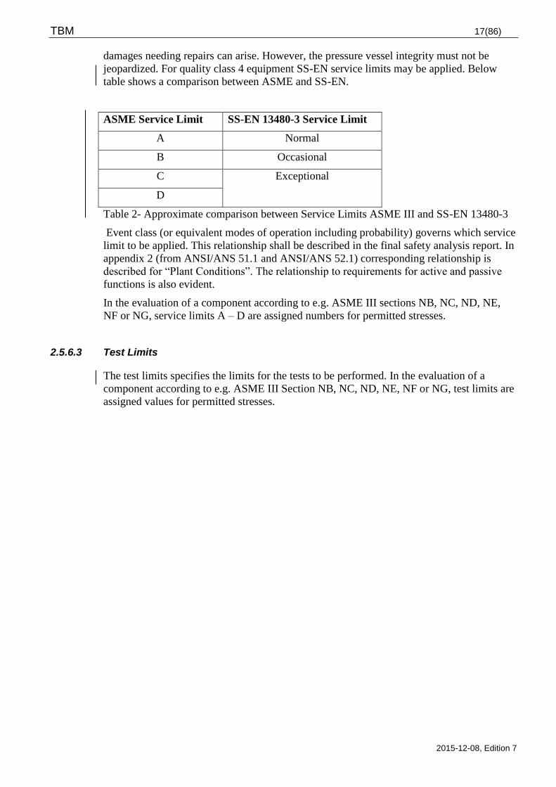
damages needing repairs can arise. However, the pressure vessel integrity must not be
jeopardized. For quality class 4 equipment SS-EN service limits may be applied. Below
table shows a comparison between ASME and SS-EN.
ASME Service Limit SS-EN 13480-3 Service Limit
A Normal
B Occasional
C Exceptional
D
Table 2- Approximate comparison between Service Limits ASME III and SS-EN 13480-3
Event class (or equivalent modes of operation including probability) governs which service
limit to be applied. This relationship shall be described in the final safety analysis report. In
appendix 2 (from ANSI/ANS 51.1 and ANSI/ANS 52.1) corresponding relationship is
described for “Plant Conditions”. The relationship to requirements for active and passive
functions is also evident.
In the evaluation of a component according to e.g. ASME III sections NB, NC, ND, NE,
NF or NG, service limits A – D are assigned numbers for permitted stresses.
2.5.6.3 Test Limits
The test limits specifies the limits for the tests to be performed. In the evaluation of a
component according to e.g. ASME III Section NB, NC, ND, NE, NF or NG, test limits are
assigned values for permitted stresses.
TBM 18(86)
2015-12-08, Edition 7
3 MATERIAL, DESIGN AND MANUFACTURING AND INSTALLATION
3.1 Material
General conditions relating to quality assurance, prescribed authorisations and requirements
for testing and inspection are given in the licensee’s Quality Regulations for Mechanical
Equipment (KBM).
Well-proven and documented material shall always be selected. If alternative codes,
standards or specifications are desired to be used, these to be approved by the licensee prior
to application and they shall at least provide equal quality
Material and shapes shall be inspected, tested and documented with certificates according
to the requirements of KBM.
Marking of material shall be performed by a method that provides permanent marking
without affecting function or material properties.
The supplier shall be responsible for the detailed selection of material standard or material
specification to be applied for the individual item. The supplier is also responsible for
conformance with the requirements, guidelines and restrictions specified below.
The licensee shall evaluate and approve or alternatively reject, the materials proposed by
the supplier.
Examples of materials that can be used in pressure retaining equipment are metallic
materials for pressure vessels as per EN or ASME Section II.
Generally, the materials are accepted as per the requirements and restrictions specified in
the respective material standard / material specification and applicable technical delivery
and inspection requirements. In addition shall the below restrictions and limitations be
adhered for the specified groups of material.
3.1.1 Metallic Materials
3.1.1.1 Cobalt
The very long-lived cobalt isotope Co-60 is the cause of most radiation in nuclear plants.
Cobalt originates from contents of cobalt in the metallic materials, which are worn,
corroded or worked into grinding dust. These corrosion- and grinding products particles are
spread with the reactor water into the core where they are activated. Thereafter they are
again distributed into the systems and are deposited in different components as extremely
severe radiation sources. To minimise the collective dose the requirements below must be
fulfilled:
The cobalt content must not exceed 0,05 % in the reactor vessel or it’s internal parts. This is
also valid for large areas (>10 m2) outside the reactor vessel if the areas are exposed to
water, which thereafter may enter the reactor vessel without passing through and ion
exchanger.
For areas 10 m2 the cobalt content must not exceed 0,20% in components that are in
contact with water that may enter the reactor unless the water first is passing through an ion
exchanger.
TBM 19(86)
2015-12-08, Edition 7
Att hardfacing in valves may a certain increased degree of cobalt content be accepted after
approval from the licensee. See chapter 4.3.2.2.
For materials in systems where the water not can enter the reactor vessel there is no
limitation of the cobalt content.
3.1.2 Silver
The silver isotopes Ag-108 and Ag-110m causes radiological problems similar to those
caused by the cobalt isotope Co-60 and the antimony isotope Sb-124. In addition to that
silver increases the dose in the plant also the nuclides difficult to filtrate, this in turn causes
increased discharges. Silver is found in e.g. certain gaskets. Silver may only be used after
approval from the licensee.
3.1.3 Antimony
The antimony isotope SB-124 causes radiological problems similar to those caused by the
cobalt isotope Co-60 and silver isotopes Ag-108 and Ag-110m. Antimony is used as an
additive in lead-, copper- tin- and zinc alloys to increase the hardness. Known sources of
antimony are pump bearings, gaskets and braids in stuffing boxes. Antimony may only be
used after approval from the licensee.
3.1.4 Aluminium and Zinc
Aluminium and zinc or alloys containing these elements shall be avoided in the reactor
building, this since when subjected to corrosion hydrogen gas is emitted. In the case where
it is not possible to avoid these elements is acceptance from the licensee first required.
3.1.5 Carbon steel and low alloy steel
Micro alloyed steels must not be used in process systems unless accepted by the licensee,
this regardless of operating temperature. This also applies to other steel structures that are
long term subjected to temperatures above 100°C.
For steels to be welded the carbon content must not exceed 0,23%, the sulphur content must
not exceed 0,030% and the phosphorus content may not exceed 0,035%.
3.1.6 Martensitic and martensitic- austenitic steels
Due to impaired welding properties martensitic and martensitic-austenitic steels must not
be used unless approved by the licensee, this also applies to precipitation hardened
martensitic steels (PH-steels). The requirement applies to pressure- and force retaining
applications. For machine parts, se chapter 4.3.2.2 (valves and 4.4.2.2 (pumps).
3.1.7 Ferritic and ferritic-austenitic (duplex) stainless steel
These steel types may only be used at permission from the licensee and where specified in
TBM.
TBM 20(86)
2015-12-08, Edition 7
3.1.8 Stainless steel castings
Stainless steel castings are not permitted in pressure retaining components in quality class 1
and 2 unless approved by the licensee. When austenitic steel castings is accepted shall the
contentment of free ferrite be 5-20% and the carbon content must not exceed 0,030% in
stainless steel casting.
3.1.9 Austenitic stainless steel
The following applies to stainless austenitic steels:
Grain size shall comply with KBM EP 2-08.
The material shall be free from cracks at the intergranular corrosion test according to
SS-EN ISO 3651-2 Method A, B or C, alternatively according to ASTM A262/E.
Corrosion requirement as per KBM EP 2-07.
The material shall be delivered in solution annealed condition.
In systems containing steam or water with an operation temperature above 100°C
precipitation hardened materials may not be used (for example 1.4980/SS 2570).
In PWR-plants, following applies:
In water borne or steam systems with operational temperature above 100º C, the carbon
content must not exceed 0,03 % for plastically formed materials. This also applies to
titanium- or niobium stabilised materials.
For other details is the maximum permitted carbon content 0,05%.
In BWR-plants the following applies:
Quality class 1-3
In water borne systems with operational temperature above 100º C, the carbon content
must not exceed 0,02 % for plastically formed materials. This also applies to titanium-
and niobium stabilised materials. For other materials is the maximum permitted carbon
content 0,05%.
For details with operational temperature below 100º C, the carbon content must not
exceed 0,03 %
The molybdenum content in plastically formed steels shall be minimum 2 %.
Quality class 4A and 4
Carbon content maximum 0,03% with exception for force retaining applications in dry
environment where specified material standard applies.
3.1.10 Nickel based alloys type NiCrFe
Nickel based alloys are accepted with the following restrictions:
The carbon content must not exceed 0,05 %.
TBM 21(86)
2015-12-08, Edition 7
Alloy X-750 may only be used in heat treated condition. The heat treatment shall be
solution annealing at 1080 + 15° C and a soaking time of 1-2 hours. Cooling through
water- or oil hardening. Precipitation hardening at 715 + 15° C and a soaking time of 20
hours followed by cooling in air.
Welding in precipitation hardened NiCrFe-alloys type Alloy X-750/A-718 must not be
performed without permission from the licensee.
Cold working is only permitted when it due to manufacturing reasons cannot be avoided.
In such cases a cold working up to 3% may be permitted.
3.1.11 Materials for salt water systems
Titanium alloys, rubber lined carbon steels and for salt water specially developed stainless
steels shall be used in salt water systems. Austenitic stainless steels shall have a
molybdenum content minimum of minimum 6% whilst ferrite austenitic (duplex) stainless
steels shall have a minimum molybdenum content of minimum 3 %. The composition shall
in addition also satisfy the criteria PRE (Pitting Resistance Equivalent) > 37, whilst PRE is
calculated according to the following formula: PRE = Cr+3,3×Mo+16×N. For certain
components may also other materials be permitted upon acceptance from the licensee. For
polymeric materials see chapter 3.1.15.
3.1.12 Materials for intermediate drainage
For intermediate drainage piping shall one of the following or equivalent material be used:
1.4563 / UNS S08028
1.4424 / UNS S31500
1.4462 / UNS S32205
1.4539 / UNS N08904
3.1.13 Materials for bolts, nuts and washers
Bolts and nuts in pressure-retaining and load-bearing equipment shall be manufactured
from materials according to SS-EN 1515-4, alternatively ASME SA-193, ASME SA-194 or
ASME SA-540 for bolting in special applications.
Bolted connections in carbon steel shall normally have bolts of strength class 8.8 or ASME
SA-193 Grade B7, nuts shall be of strength class 8 or ASME SA-194 gr 2H and plain
washers of hardness class 200 HV.
For pressure above 40 bar or temperature above 300°C must not bolt in strength class 8.8 or
nut in strength class 8 be used, alternative materials must be chosen in accordance with SS-
EN 1515-4.
Bolt in stainless steel shall normally be manufactured in material A4-70 or ASME SA-193
Grade 8M Class 1 and nut in material A4-70 or ASME SA-194 Grade 8M.
Upon acceptance from the licensee may also A2-70 or ASME SA-193 Grade B8 Class 1 be
accepted for bolt and A2-70 or ASME SA-194 Grade 8 for nut. However, A4-80 or A2-80
are not permitted.
Plain washers in stainless steel shall be of hardness class 200 HV.
TBM 22(86)
2015-12-08, Edition 7
If stainless bolts are chosen, the risk of galling to be considered. Bolts of austenitic
stainless materials with a hardness exceeding 220 HV must not be used in direct contact
with water at a temperature above 100º C.
Head bolts must not be used at pressure exceeding 40 bar or at temperatures above 150°C.
At higher pressure rating or higher temperature stud bolt or threaded bar of bolting material
to be used. Threaded bar /Stud bolts in the above material shall always be used in quality
class 1.
Bolted connections in carbon steel as well as stainless steel may require a higher strength
class at high torque and thus higher hardness class of the washers thereto.
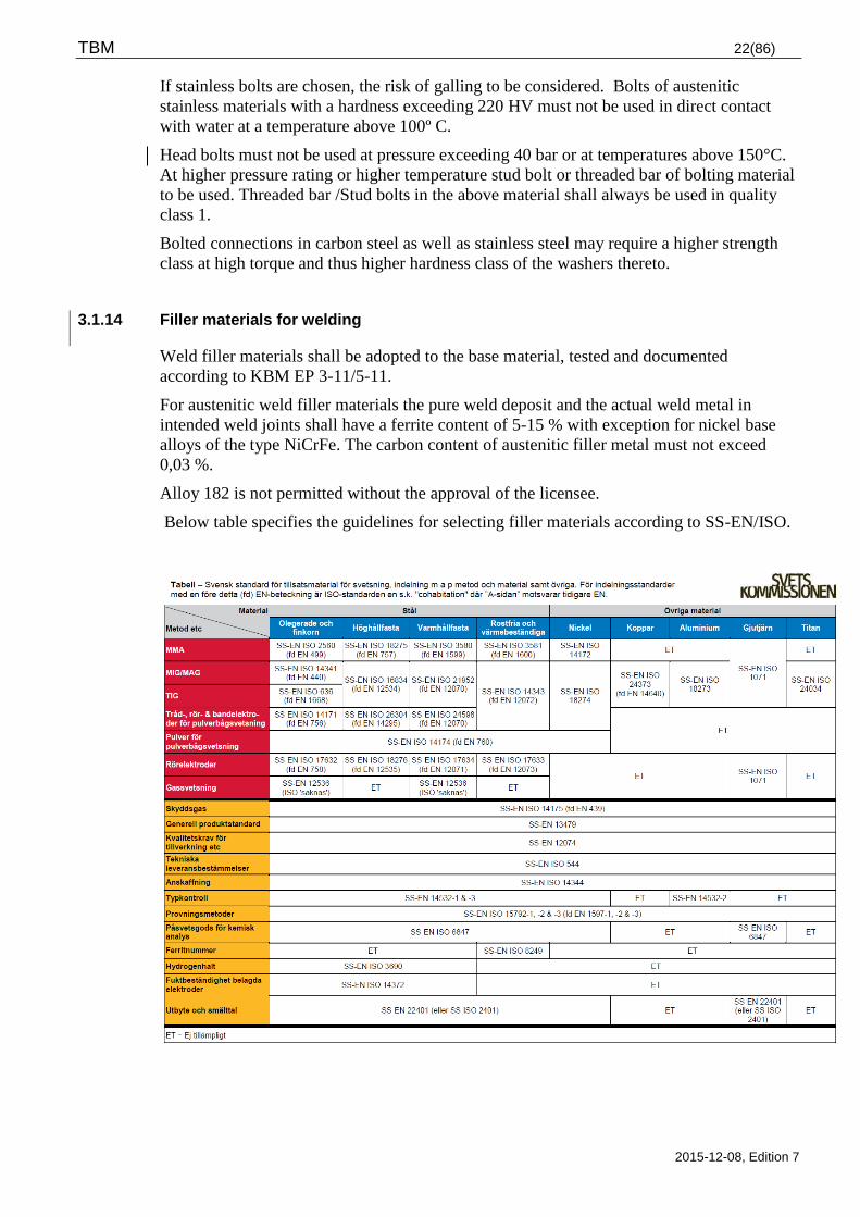
3.1.14 Filler materials for welding
Weld filler materials shall be adopted to the base material, tested and documented
according to KBM EP 3-11/5-11.
For austenitic weld filler materials the pure weld deposit and the actual weld metal in
intended weld joints shall have a ferrite content of 5-15 % with exception for nickel base
alloys of the type NiCrFe. The carbon content of austenitic filler metal must not exceed
0,03 %.
Alloy 182 is not permitted without the approval of the licensee.
Below table specifies the guidelines for selecting filler materials according to SS-EN/ISO.
TBM 23(86)
2015-12-08, Edition 7
3.1.15 Plastic and rubber
Halogen based materials as fluorine rubber, chloroprene, chlorethene, sulphone rubber,
teflon and PVC, are not permitted for use in nuclear power plants without the approval of
the licensee. Plastic and rubber materials free from halogens are primarily used for sealing
elements, O-rings, cable insulation and seawater coolant piping.
For polymers in contact with high temperature water (>100º C) there are requirements for a
highest content of leachable chlorides and fluorides of totally150 mg/kg.
The licensee shall specify area of application, environment and operation temperature.
Depending of the component function expected radiation dose and temperature after
possible accident to be considered.
Detailed material specification shall be requested from the supplier. Polymers age,
especially at elevated temperatures and at irradiation, the manufacturer shall due to these
circumstances recommend the periodic replacement of the component in question.
Polymer materials demonstrate different resistance against radiation.
Polytetrafluoroethylene (PTFE, e.g. Teflon) is the most radiation sensitive polymer and it
must not be subjected to an accumulated radiation dose exceeding 5*10² Gy. Also
polyacetals (e.g. Delrin) are sensitive to gamma radiation, this should be considered in the
applications where high radiation levels can be expected.
Peroxide vulcanized rubber demonstrates in general a higher temperature- and radiation
resistance than sulphur vulcanized rubber.
Plastic pipe should only be used in quality class 3, 4A and 4 where the medium is sea
water, industrial or demineralised water. The materials that can be used in such systems are
the thermoplastics listed in The Swedish code for plastic piping PRN 1988.
Plastic piping shall be designed, manufactured, installed, inspected and tested in accordance
with PRN 1988. As an alternative may SS-EN 13067 or EWF581 be used for qualification
of welders. Procedure for the welding is required.
Piping must not be installed in such a way that they run the risk of being subjected to fire.
3.1.16 Gasket material
Materials in mechanical shaft seals shall be selected in consultation with the licensee.
Unless otherwise specified by the licensee expanded graphite to be used in stuffing boxes.
Also filler material filler material in spiral wound gaskets and reinforced compressed
gaskets shall be of expanded graphite.
Due to risk of galvanic corrosion in adjacent equipment graphite may however not be used
in systems, which may come into contact with sea water.
The total quantity of in water leachable contents of chloride, fluoride, sulphate and
antimony at 100ºC must not exceed 150 mg/kg and in the case of pure graphite gaskets not
exceed 50 mg/kg.
Asbestos must not be used in the plant.
Rubber-bonded fibre gaskets may be used according to the recommendations of the
manufacturer, the gasket material shall however be accepted by the licensee.
Gaskets shall be designed according to applicable standard ASME B16.20, ASME B16.21,
SS-EN 1514-1, SS-EN 1514-2 and SS-EN 14772.
TBM 24(86)
2015-12-08, Edition 7
3.1.17 Lubricants
Antimony or sulphurous lubricants, e.g. molybdenum disulphide, must not be used in
BWR-water or PWR primary side. Graphite based- or graphite-nickel based lubricants to be
used as the first choice. The lubricants used must be classified, approved and registered in
chemical data base of the respective plant. For calculation of the compression force in a
bolted connection the friction value of the lubricant to be specified.
3.1.18 Thermal insulation
For thermal insulation material the requirements decided by the licensee applies for highest
in water permitted leachable content of chlorides and fluorides.
3.2 Design and calculation
Design of pressure-retaining and load-bearing equipment, shall with respect to mechanical
integrity, be made according design specifications approved by the licensee.
Calculation of mechanical integrity, shall be performed to an extent that is specified in the
below codes and standards and they shall be documented through a technical report. The
mechanical integrity analyses shall be performed against the applicable KFMs (design
criteria mechanical equipment), see chapter 2.5. Review requirements of calculations are
specified in KBM.
Design and calculation of mechanical equipment in quality class 1, 2 and 3 shall be
performed as per ASME BPVC, Section III, Subsection NB, NC, ND respective NF and
according to certain design rules and requirements in TBM chapter 3 and 4.
Pressure retaining equipment in quality class 4 and 4A containing radioactive media shall
normally be designed according to SS-EN 13480 (piping) and SS-EN 13445 (pressure
vessels) with addition of certain design rules and requirements in TBM chapter 3 and 4.
Pressure retaining equipment in quality class 4 not containing radioactive media shall
satisfy the requirements of AFS 1999:4 (PED). Design and calculation of such equipment
shall normally be performed according to SS-EN 13480 (piping) and SS-EN 13445
(pressure vessels) and according to certain design rules and requirements in TBM chapter 3
and 4.
The interpretation for the application of ASME Service Limits at calculations according to
SS-EN 13445-3and SS-EN 13480-3 is evident from table 2-1 in chapter 2.5.6.2.
Pressure retaining equipment in quality class 4A requires tightness class S or P, however,
in quality class 4 tightness class K may be applied. In tightness class S and P there are
certain requirements for flanged joints according to chapter 4.1.3 and requirements for
pump and valve seals according to chapter 4.3 and 4.4. For selecting of tightness class see
attachment 4.
The licensee may permit that design of mechanical equipment in quality class 2, 3, 4 and
4A is performed according to other codes and guidelines. A condition for this is that an
evaluation of similarity is performed. The supplier is then responsible for submitting a
written application of this acceptance from the licensee.
The certain rules to be considered for the respective equipment specific mechanical
equipment are found under “Design and calculation” in TBM chapter 4.
TBM 25(86)
2015-12-08, Edition 7
3.3 Manufacturing and installation
This chapter specifies to applicable parts the minimum requirements at manufacturing,
installation and welding of quality classed mechanical equipment. Companies
manufacturing such equipment shall prepare and use manufacturing- and installation
documents that are approved by the licensee. This shall with respect to design and
configuration satisfy the requirements of TBM and other requirements as per the below
specified standard. The rules for inspection, testing, welding and heat treatment in these
standards shall however then be replaced by the requirements of KBM and TBM.
Manufacturing and installation of mechanical equipment in quality class 1-3 shall be
performed as per ASME BPVC, Section III, Subsection NB, NC, ND respective NF and
according to certain requirements in TBM. SS-EN 13445-4 (pressure vessels) and SS-EN
13480-4 (piping) may be used after approval from the licensee.
Manufacturing and installation of mechanical equipment in quality class 4 and 4A shall be
performed in accordance with SS-EN 13480-4 and SS-EN- 13445-4 and to certain
requirements in TBM. Other standards such as e.g. ASME VIII may be used after approval
from the licensee.
Manufacturing of pressure retaining equipment not containing radioactive media shall fulfil
the requirements of AFS 1999:4 (PED). However AFS 1999:4 shall not be used at
installation, SSMFS 2008:13 (KBM) shall rather be used.
3.3.1 Standards for welding
All welding of mechanical equipment in quality class 1-3, 4 and 4A shall be performed
according the standards and requirements specified in chapter 3.3 and KBM chapter 1.6,
with the exception of quality class 4 for equipment not containing radioactive media, for
such equipment AFS 1999:4 (PED) applies.
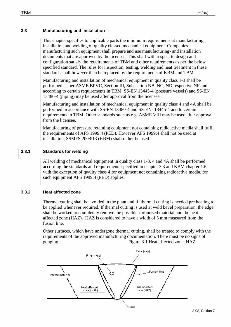
3.3.2 Heat affected zone
Thermal cutting shall be avoided in the plant and if thermal cutting is needed pre heating to
be applied whenever required. If thermal cutting is used at weld bevel preparation, the edge
shall be worked to completely remove the possible carburised material and the heat-
affected zone (HAZ). HAZ is considered to have a width of 5 mm measured from the
fusion line.
Other surfaces, which have undergone thermal cutting, shall be treated to comply with the
requirements of the approved manufacturing documentation. There must be no signs of
gouging. Figure 3.1 Heat affected zone, HAZ
TBM 26(86)
2015-12-08, Edition 7
In the event of adverse effects on the mechanical properties resulting from any
manufacturing process or from incorrect handling, the properties shall be restored through
heat treatment in accordance with a procedure approved by the licensee.
All old weld material and HAZ shall be removed when connecting against existing system
or equipment. At cutting shall normally the double HAZ width be removed.
At seal welding and lock welding re-welding can be permitted in HAZ.
3.3.3 Requirements for temporary welds
Temporary supports or other devices may be welded to equipment during manufacturing
and installation providing that the material can be identified, is possible to weld and the
material is compatible with the base material. After removal of the temporary attachments
the weld area in the base material to be marked up and examined with liquid penetrant test
or magnetic particle test. The testing to be performed and documented as per KBM
requirements.
WPS for temporary welds shall be approved identically as for permanent welds.
3.3.4 Requirements for handling of stainless steels and nickel-based alloys
In order to avoid contamination austenitic stainless steel to be handled totally separately
and without contact with carbon steel or low alloy steel.
Only hand tools, files and polishing materials, stainless steel wire brushes etc. designated
for working on stainless and nickel-based alloys may be used. Tools such as jigs, fixtures
etc. shall be provided with sufficient stainless cladding to prevent contact with other
materials such as carbon steel, copper, bronze, lead and zinc.
In addition the following applies:
Equipment shall have a degree of cleanliness specified by the licensee.
The concentration of fluoride, chloride and sulphate shall be kept at lowest possible level
and at limiting values specified by the respective licensee.
Care shall be taken to prevent contamination from halogens and carbon steels, copper,
zinc, lead, and other heavy metals.
At blasting clean glass media is preferred that has not been used for blasting of different
type of material. If other blasting media is used this has to be approved by the licensee.
Wire brushes shall be made of the same material group and must not have been used for
cleaning of other material.
External areas not in contact with media a limited number of small paint stains, rust
stains and traces of colour marking are permitted.
Shall not be bundled with band of carbon steel unless use of spacers.
Shall be stored indoors on clean and dry surface.
Material of austenitic stainless steel and nickel base alloys must not come into contact
with packing material, tape etc. containing in water leachable halogens.
Grinding and blasting of austenitic stainless steels or nickel-based alloys requires the
consent of the licensee if the zone in question will subsequently be in contact with primary
TBM 27(86)
2015-12-08, Edition 7
water at a temperature above 100ºC. Polishing or wire brushing as well as glass blasting for
removal of the surface oxide is however permitted. Also well sharpened rotating file may
be used since this prevents against high surface temperatures. Rotating power wire brushing
shall be avoided and may only be used after approval from the licensee. The licensee shall
approve all working methods that are used.
3.3.5 Welding
Company that is welding and welders associated with the company shall hold authorization
for welding in accordance with requirements of KBM. A supplementary welder site
qualification test shall be carried out when the licensee considers this necessary.
Welding of pressure vessels and piping > DN 50 (> 2” NPS) and wall thickness > 6 mm in
quality class 1 and class 2 systems shall be performed with mechanized welding methods,
accessibility for welding shall be regarded. Deviations shall be motivated and accepted by
the licensee. This requirement does not apply to welding of nozzles and branch connections
welded directly to the main pipe.
The weld filler material shall be adopted to the base material and tested and document
according to the requirements of KBM.
At welding of components adjacent to reactor should TIG and MMA be used, however also
other welding methods can be permitted e.g. plasma welding and laser welding. Manual
metal inert gas welding/metal active gas welding (MIG/MAG) must not be used for
internal reactor vessel parts or in quality class 1-3 unless accepted by the licensee.
At welding in quality class 4 and 4A outside the reactor vessel there is no certain
acceptance required from the licensee providing that the welding method is well proven
within the nuclear power area. Gas welding must not be employed.
At metal-arc welding with coated electrodes in low alloy steels, basic electrodes with
hydrogen content H5 or lower to be used.
3.3.6 Fit up and tack welding
Tack welding is permitted in accordance with the following:
Root tack may remain if longer than 2 x t, however, minimum 6 mm if the material
thickness of the tack <2,0 mm and the ends are tapered down before welding.
Carried out with a round bar or bridge and welded to the weld bevel edges and removed
by grinding.
Carried out with clips and welded on both sides outside a finished weld. After welding,
the clips shall be ground off and the surface tested with liquid penetrant – or magnetic
particle test and documented in accordance with the requirements in KBM.
The requirement of approved welding procedure and authorisation for welding also applies
to tack welding.
At manufacturing and installation shall applicable values for edge misalignment, bevelling
etc. fulfil requirements of SS-EN ISO 5817. Discrepancies shall be reported and corrected.
Permanent discrepancies shall be documented, and submitted to the licensee for
assessment, whereupon the work will be corrected or approved.
TBM 28(86)
2015-12-08, Edition 7
3.3.7 Weld procedure / welding data sheets (WPS)
The manufacturer shall establish welding procedures (WPS) according to SS-EN ISO
15609-series for the welding operation in question. The welding procedures shall be based
on approved WPQR (Welding Procedure Qualification Record) according to applicable part
of the SS-EN ISO 15614 or SS-EN ISO 15613 with additional technical requirements
requested by the licensee. The welding procedures shall be approved by the licensee.
3.3.8 Certain requirements for weld joints
In respect of external discontinuities and deviations in shape, finished welds in pressure-
retaining and load-bearing components shall, as a minimum, comply with the quality level
B according to SS-EN ISO 5817.
Pipes DN<10 (< 3/8” NPS), the height of the root reinforcement must not exceed 10 % of
the inside diameter of the pipe.
The weld crown shall have a surface roughness of Ra 16 m or better when the weld is to
be examined by ultrasonic testing.
Surfaces adjacent to welds that shall be examined with ultrasonic testing (see figures in
chapter 4.1.2) must not show irregularities such as arc strikes, weld spatter, paint traces or
similar.
Weld clad surfaces in low-alloy material to be ultrasonic tested shall have a surface
roughness, equal to or better than Ra 16 m.
Other weld joints shall at least comply with the requirements of weld class C in SS-EN ISO
5817. For painted products also see requirements of chapter 3.4.3.
In addition the following applies to welds in austenitic stainless steels:
Due to the risk of crevice corrosion, design in process media water shall be performed to
avoid HAZ in crevice areas. This does not apply to socket welds performed as per chapter
4.1.2.
Welding shall be performed with method minimising sensibilisation.
Welds shall always be purged with shielding gas on the root side. At the welding of lugs or
similar from the outside, the pipe to be purged with shield gas alternatively filled with
water when the wall thickness is below 12 mm.
Austenitic stainless steel intended for a design temperature above 100°C that is welded or
may be repair welded must not be ground without subsequent solution annealing
Stainless steel surfaces in water borne process systems shall satisfy the requirements as per
oxide reference “C” in appendix 3. For other systems may under certain conditions “D” be
accepted. During a transition period and upon the acceptance from the licensee can also
earlier oxide reference “17” according to TBM 6.0 appendix 4 be accepted.
For welding in primary water systems with an operating temperature exceeding 100C the
interpass temperature must not exceed 100C.
At installation in the plants and at manufacture of new components the distance between
weld joint edges should be no less than 150 mm and never less than 50 mm.
Pickling and passivation must not be performed without permission from the licensee.
TBM 29(86)
2015-12-08, Edition 7
For weld joints between austenitic stainless steel and carbon steel respectively low
alloy steel i.e. dissimilar welds the following applies:
Weld filler metals shall always be used and the gap between the weld edges shall be >1,5
mm. The root side to be purged with shield gas.
Strive for welding in a workshop and a at horizontal position
3.3.9 Repair Welding of base material
Materials for bolts and nuts must not be weld repaired.
Plastically formed material such as plate, pipe, bar and forging must not be weld repaired
unless accepted by the licensee.
Welding procedures are required. Weld repaired areas shall satisfy the requirements on the
base material and to be inspected in accordance with approved detailed inspection plan and
requirements stipulated in non-conformance report.
Licensee permission is required for extensive repair weld of cast iron or steel casting, the
repair procedure shall also be approved by the licensee.
A repair is regarded as extensive if:
Cast iron and steel castings shows defects that may cause leaks at pressure testing
The ground out /prepared cavity is deeper than 15 mm or 10% of the wall thickness or
any flaw that got an area exceeding 50 cm².
The following requirements applies prior to repair welding:
Requirements for welding authorisation as per KBM shall be satisfied
The supplier shall possess weld repair procedure as per the respective case above. The
welding procedures shall prior to use be approved by the licensee.
The following applies after performed repair weld:
All repair welds shall be documented
The surfaces shall after the repair weld be thoroughly worked over in order to achieve a
smooth transition with the surrounding base material
The repair welded material shall be heat treated in accordance with the requirements in
approved material specification/standard
Repair welded area shall satisfy the requirements of the base material and be inspected
as per the requirements of KBM.
3.3.10 Repairs of welds
One single weld in equipment with operation temperature above 100°C must not undergo
more than three local repairs with a distance of less than 50 mm between the repairs. In the
case where additional repairs are required, the entire weld to be cut, new weld bevels to be
TBM 30(86)
2015-12-08, Edition 7
prepared where the entire heat affected zone (HAZ) shall be removed. At more than one
weld repair within the same area is licensee approval required.
The following requirements applies prior to repair of weld:
Requirements for welding authorisation as per KBM shall be satisfied
The supplier shall possess weld repair procedures approved by the licensee
The following applies after performed repair weld:
All repairs of welds shall be documented
The repaired material shall be heat treated in accordance with the requirements in
approved WPS/standard
Repair welded area shall satisfy the requirements of the initial weld and be inspected
against an inspection plan that is approved by the licensee.
3.3.11 Forming and straightening
All forming and straightening shall be performed prior to final inspection, i.e. prior to
visual and dimensional examination and non-destructive testing.
Prior to forming, a forming procedure shall always be approved by the licensee. In the cases
where qualification of forming procedure is required, the result of the qualification shall
also approved by the licensee. Procedure and possible qualification reports shall also be
included in the documentation that shall be approved by an accredited inspection body.
Data in the applicable material standards regarding forming and data from the material
manufacturer shall be observed.
3.3.11.1 Forming Procedure
The manufacturer shall establish procedures for forming, bending, rolling expansion of
tubes and major straightening operations. The documentation for the forming shall to
applicable extent contain the following:
Type of forming and straightening, e.g. cutting, preparation of weld bevel, rolling,
induction bending, and hot straightening
Type of material and stock shape
Dimension of materials
Work procedure, equipment, cleanliness requirements before and after forming
Material forming temperature, cooling temperature, equipment for temperature
measurement
The effect of the method upon hardness, microstructure, result of intergranular corrosion
testing
Possible requirements for post-heat treatment
Requirements for dimension, ovality, surface condition, and permanent cold deformation
Inspection of finally formed parts.
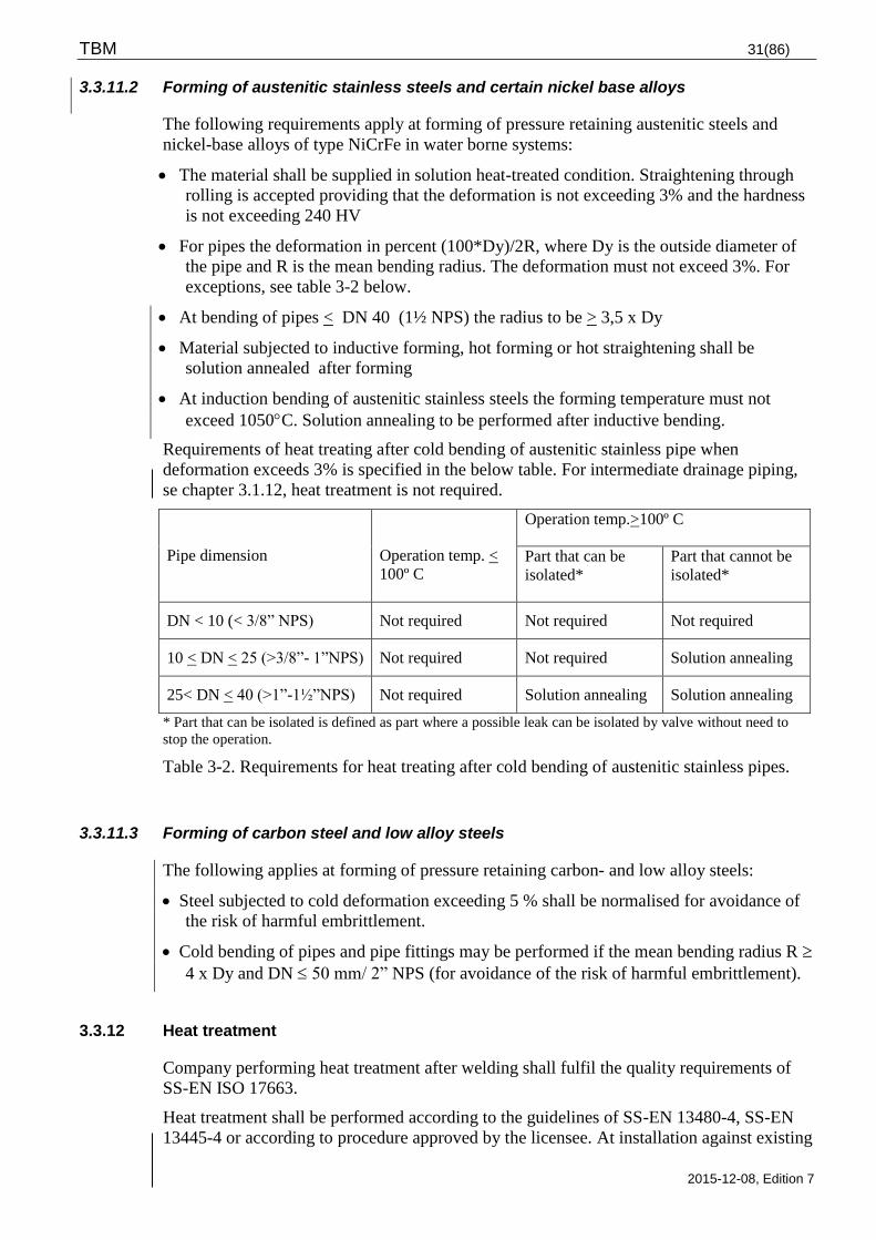
TBM 31(86)
2015-12-08, Edition 7
3.3.11.2 Forming of austenitic stainless steels and certain nickel base alloys
The following requirements apply at forming of pressure retaining austenitic steels and
nickel-base alloys of type NiCrFe in water borne systems:
The material shall be supplied in solution heat-treated condition. Straightening through
rolling is accepted providing that the deformation is not exceeding 3% and the hardness
is not exceeding 240 HV
For pipes the deformation in percent (100*Dy)/2R, where Dy is the outside diameter of
the pipe and R is the mean bending radius. The deformation must not exceed 3%. For
exceptions, see table 3-2 below.
At bending of pipes < DN 40 (1½ NPS) the radius to be > 3,5 x Dy
Material subjected to inductive forming, hot forming or hot straightening shall be
solution annealed after forming
At induction bending of austenitic stainless steels the forming temperature must not
exceed 1050C. Solution annealing to be performed after inductive bending.
Requirements of heat treating after cold bending of austenitic stainless pipe when
deformation exceeds 3% is specified in the below table. For intermediate drainage piping,
se chapter 3.1.12, heat treatment is not required.
Pipe dimension
Operation temp. <
100º C
Operation temp.>100º C
Part that can be
isolated*
Part that cannot be
isolated*
DN < 10 (< 3/8” NPS) Not required Not required Not required
10 < DN < 25 (>3/8”- 1”NPS) Not required Not required Solution annealing
25< DN < 40 (>1”-1½”NPS) Not required Solution annealing Solution annealing
* Part that can be isolated is defined as part where a possible leak can be isolated by valve without need to
stop the operation.
Table 3-2. Requirements for heat treating after cold bending of austenitic stainless pipes.
3.3.11.3 Forming of carbon steel and low alloy steels
The following applies at forming of pressure retaining carbon- and low alloy steels:
Steel subjected to cold deformation exceeding 5 % shall be normalised for avoidance of
the risk of harmful embrittlement.
Cold bending of pipes and pipe fittings may be performed if the mean bending radius R
4 x Dy and DN 50 mm/ 2” NPS (for avoidance of the risk of harmful embrittlement).
3.3.12 Heat treatment
Company performing heat treatment after welding shall fulfil the quality requirements of
SS-EN ISO 17663.
Heat treatment shall be performed according to the guidelines of SS-EN 13480-4, SS-EN
13445-4 or according to procedure approved by the licensee. At installation against existing
TBM 32(86)
2015-12-08, Edition 7
systems in material 15Mo3/16Mo3 thickness 15<t<35 mm shall the need of heat treatment
be evaluated by the manufacturer and to be approved by the licensee.
Heat treatment after welding shall be performed to the extent stated in the welding
procedure approved by the licensee. Other heat treatment shall be performed according to
respective material standard or as per a heat treatment procedure approved by the licensee.
Heat treatment shall be performed prior to the final inspection.
Where applicable, a heat treatment procedure shall be established by the supplier and shall
to applicable extent contain the following:
Type of heat treatment equipment such as furnace and induction heating equipment
Type of temperature measuring device, location and number of measuring points
Recording equipment for temperature and time sequences
Atmosphere, insulation materials, cleanliness requirements
Heat treatment range of item with respect to temperature and holding time
Heating rate
Cooling rate
Procedures to be followed in the event of interruption in the heat treatment
Procedure for pickling when applicable.
Calibration records or similar for temperature measuring and laboratory equipment shall be
presented.
Data from the applicable material standard as well as the manufacturer's recommendations
relating to heat treatment shall be observed.
Heat treatment procedures shall be approved by the licensee prior to start of heat treatment.
3.3.13 Marking
Pressurised equipment shall to applicable parts be marked as per the requirements of
SSMFS 2008:13 4 chapter 12§. Also see requirements of KBM EP 2, -4, -6-09.
Manufacturers of equipment and equipment parts shall be responsible that material or items
cannot be interchanged and that the relationship between material and certificate is
constantly maintained until inspection of the finished equipment or equipment part has been
completed and documented by the parties responsible, according to the inspection plan.
When dividing material the supplier is responsible for transferring of marking to all parts.
Marking of material parts or items shall be carried out with a method minimising risk of
material mix up, without impact to the function of the component or the material properties.
For material thickness < 5 mm a blunt-nosed stamp must not be used.
For pressure retaining details, which due to functional reasons cannot be marked and for
small items where only certificate of conformance is required, individual marking may be
replaced by package marking and the material to be administrated according to the
licensee’s QA routines.

TBM 33(86)
2015-12-08, Edition 7
TBM 34(86)
2015-12-08, Edition 7
3.4 Surface treatment
3.4.1 General
Requirements in plant specific procedure for surface treatment to be applied
The manufacturer shall have routines for cleaning and inspection of cleanliness. The
manufacturer shall also present results from performed cleanliness inspection.
It shall be strived for a high degree of cleanliness at all manufacturing steps, at
manufacturing and testing, at storing, packaging and transportation. A high degree of
cleanliness at manufacturing and intermediate storing is a precaution for the guarantee of a
good final cleanliness.
Surfaces shall be free from visible contamination and lose particles. A thin stain free
adherent film of oxide on cleaned surfaces developed at heat treatment in oil- or carbon free
atmosphere can be accepted, also a very thin layer of rust on carbon steel surfaces can be
accepted.
Unless otherwise specified shall the manufacturer present a program to the licensee,
containing cleaning, pre-treatment and surface treatment, appropriately performed prior to
functional test or pressure- and tightness test.
Pressure and tightness test of piping installations, valves, pumps etc. shall be as per the
inspection plan prior to surface treatment.
All surface coating, including corrosion protection and temporary corrosion protection
(preservation/transportation protection) shall be performed in accordance with plant
specific procedure for surface treatment and with products approved by the licensee.
The risk of hydrogen embrittlement shall be regarded.
3.4.2 Painting-, Corrosivity- and Environment classes
Corrosion protection of equipment at nuclear plants stems from below different classes.
Painting classes:
Class Examples of areas
I The Reactor building only
II The rooms within controlled area
III The rooms outside controlled area
IV The areas with high humidity (>90% RH) and areas entirely or from time to
time are under water, or from time to time condensed within or outside
controlled area
V Office buildings or similar
VI Outdoors
TBM 35(86)
2015-12-08, Edition 7
Corrosivity classes according to SS-EN ISO 12944-2:
C1 Very low
C2 Low
C3 Medium
C4 High
C5-I Very high (industry)
C5-M Very high (marine)
Im 1 Fresh water
Im 2 Salt- or brackish water
Im 3 Earth
Environment class according to Asea-Atom
Environment class N1
Normal, dry to moderately humid indoors environment. No risk of condensation on painted
area. Corrosivity class C2 according to SS-EN ISO 12944-2.
Environment class N2a
Indoors on surfaces subjected to radioactive contamination and humidity and condense.
Corrosivity class C2 and C3 according to SS-EN ISO 12944-2.
Environment class N2b
Indoors on surfaces subjected to radioactive contamination and humidity and condense.
Corrosivity class C4 according to SS-EN ISO 12944-2.
Environment class V
Water, unventilated rock ground rooms etc. corresponding corrosivity class C4, C5-I,
C5-M or IM 1-3 according to SS-EN ISO 12944-2.
Environment class R1
The reactor isolation building, the upper or lower primary area.
Environment class R2
The reactor isolation building condensation area
Environment class U
Outdoors corresponding corrosivity class C5-M at Ringhals or C4 at Oskarshamn and
Forsmark according to SS-EN ISO 12944-2.
3.4.3 Design and pre-treatment
The construction shall be made in order to enable the pre-treatment and application of the
corrosion protective primer in a technical correct way. Recommendations in SS-EN ISO
12944-3 to Annex A-D to be regarded. For constructions in a very aggressive environment
the class Good as per SS-EN ISO 12944-3 is a minimum requirement.
The object shall be inspected and approved by an individual that is knowledgeable in
painting prior to turning it over for painting.
The manufacturing documents shall unambiguously specify the areas to be painted.
Requirements for pre-treatment of non-machined areas:
TBM 36(86)
2015-12-08, Edition 7
Non-machined surfaces that after pre-treatment will be surface protected shall satisfy SS-
EN ISO 8501-1 as per below:
Minimum rust degree B for internal surfaces in vessels that belongs to coating class IV.
Minimum rust degree C for other areas.
Requirements for surface to be painted:
The surface shall be clean, also clean from chlorides and sulphates, the surface shall be
uniform i.e. no weld slag, sharp edges and burrs etc. Welds shall be free from discontinues.
Objects in coating class IV shall satisfy pre-treatment degree P3 and welds quality level B,
other coating classes applies pre-treatment degree P2 and quality level C according to SS-
EN ISO 8501-3 respectively SS-EN ISO 5817:2007.
Intermittent weld is not permitted for objects in coating class IV.
3.4.4 Painting
Recommendations from paint manufacturer shall be adhered unless otherwise specified in
plant specific surface treatment procedure or data sheet for the type of treatment. Paint
manufacturer or subcontractor must not alter the relevant procedure without approval from
the licensee’s chemistry- and environment department. Painting of expansion bolts shall be
avoided.
3.4.4.1 Supplier’s standard painting system
The respective licensee shall provide a document listing the requirements of coating
systems and paints.
The supplier’s standard coating system can be accepted, all depending of coating- and
environment class for the object and area in question.
It shall be ensured that items coated with standard procedure that the coating product /
coating system withstands the environment in a nuclear power plant.
New coating product / coating system to be used on steel surfaces must satisfy the relevant
requirements of the plant specific coating procedure (dependant on the coating class of the
object), see plant specific surface treatment specification e.g.:
Maximum permitted contents of certain elements
Resistance against radiation
Suitability for decontamination
Resistance against demineralised water
Fire
Chemicals
TBM 37(86)
2015-12-08, Edition 7
In general coating products / coating systems must not be based on chlorine rubber paints
or polyvinyl chloride.
3.4.5 Galvanizing
Zinc and aluminium shall be avoided in the reactor building, see chapter 3.1.4.
Hot dip galvanizing, may to a certain extent be used as an alternative to painted
constructions, this applies to details such as grid greatings and greating plates, electrical
raceways, ventilation ductwork, steel constructions outdoors and sheet metals in gates (in
combination with painting) etc. Hot dip galvanizing shall be performed in accordance with
SS-EN ISO 1461:2009, edition 2. Equipment for screening of water inlets and pumps
should not contain hot dip galvanized parts.
Spray zinc galvanizing of constructions are evaluated on case by case basis. The purity of
the zinc shall be 99,99%. For other details see SS-EN ISO 2063:2005 edition 1. Spray zinc
galvanizing is inappropriate in controlled area.
Electro galvanizing should only be chosen for standard products available as stock items
and are intended for dry areas. Electro galvanizing shall satisfy SS-EN ISO 2081:2008,
edition 1 Service condition 2 and for threaded steel items SS-EN ISO 4042 edition 1 or
equivalent standard applies. Electro galvanizing should be avoided for fasteners. There is
risk of hydrogen embrittlement at electro galvanizing.
3.4.6 Rubber lining
At the choice of rubber lining of pipes and equipment the suitability of the lining with
regard to ionising radiation shall always be considered.
The supplier shall provide a thorough specification of the rubber material and the rubber
lining for the approval by the licensee. The rubber lining work shall be documented by the
manufacturer.
Surfaces to be rubber lined must not have a rust degree worse than B and satisfy the pre-
treatment Sa3 according to SS-EN ISO 8501-1. Surfaces to be rubber lined must not be
pressure tested with sea water. The pressure testing of pipes and equipment shall be
finalized prior to initiation of pre-treatment. The Thickness of the rubber lining shall
normally be 4+0,4 mm.
The licensee shall provide requirements for maximum levels of material leachable
substances.
3.4.6.1 Temporary corrosion protection
The supplier shall, if requested by the licensee, prior to delivery provide a program for
temporary corrosion protection (preservation and transportation protection) for piping and
equipment. Impact on rubber details shall be considered.
TBM 38(86)
2015-12-08, Edition 7
3.4.7 Storage and Transport
Transport and delivery of components to the plant shall be carried out under such
conditions and with such packaging that the risks of damages, corrosion and contamination
are avoided. Nozzles and machined surfaces must be particularly well protected. Unless
otherwise agreed between the supplier and the licensee shall equipment at delivery be
completely dry and cleaned, see chapter 3.5.
Painted products shall be stored in well protected environment, this to achieve optimal
quality of the painting system and to facilitate sequential chemical curing. Painted details
must not be handled if imperfections may occur. Transportation may not take place prior to
complete drying of the paint (in accordance with the paint manufacturer’s data sheet) nor if
the environment at curing process not is satisfying the specified requirements. If doubts the
licensee to be contacted.
All openings shall be covered and sealed with suitable plugs or covers of material free from
halogens. Sealing shall be carried out immediately after cleanliness inspection.
3.5 Documentation
3.5.1 Necessary Documentation at Tender
In order to satisfy the licensee’s requested data in the invitation for tender shall the tenderer
submit a complete documentation package in the form of drawings, brochures, documents
for the scope of inspection etc.
In the tender documents it shall be specified whether the equipment in some respect
deviates from the requirements in the TBM and the request for tender. The tender
documents shall also include data of limitations of the inspection scope or any desire to use
other inspection methods than those stated in the KBM submitted by the licensee.
3.5.2 Documentation required prior to manufacturing
The below data shall be sent to the licensee for approval:
Drawings and calculations according to the TBM and KBM requirements
Procedures for welding, forming and heat treatment
Complementary component data to the delivered component specification
Other procedures requested by the licensee.
The drawings shall at least include the data specified in the equipment specific
requirements in chapter 4 and in prescribed codes and standards.
The manufacturer shall be responsible for the listing of all approved design and
manufacturing documentation in a document index, where the document titles and numbers
with the valid revision are clearly evident. This list of applicable design and manufacturing
documents shall be kept current by the manufacturer during the entire manufacturing
process and be part of the final documentation.
In addition shall detailed inspection documentation be submitted to the licensee to an extent
specified in KBM.
TBM 39(86)
2015-12-08, Edition 7
3.5.3 Documentation of deviations during manufacturing
All deviations to approved manufacturing and inspection documents, agreed between the
licensee and the manufacturer, shall be reported in deviation reports. The deviation report
shall be approved by the licensee before carrying out corrective action.
All repairs by welding shall be documented by the manufacturer.
3.5.4 Delivery of Technical Documentation
Final documentation shall be sent to the licensee at delivery of the equipment. The contents
and structure of the documentation shall be agreed between the licensee and the supplier.
3.5.5 Documentation of surface treatment
One set of final documentation shall be provided to the respective licensee, this should be
the original documents and contain the following:
From respective performed surface protection:
Whenever applicable, reports and protocols from certain investigations or inspections
Reports for applicable surface protection in respective form (painting, painting
according to the suppliers standard program, hot dip galvanizing, rubber lining)
Signed inspection plan including required inspection reports thereto
Non-conformance reports, if any
Report of final inspection
List of open items, if any
Report of in-house inspection for performed painting system
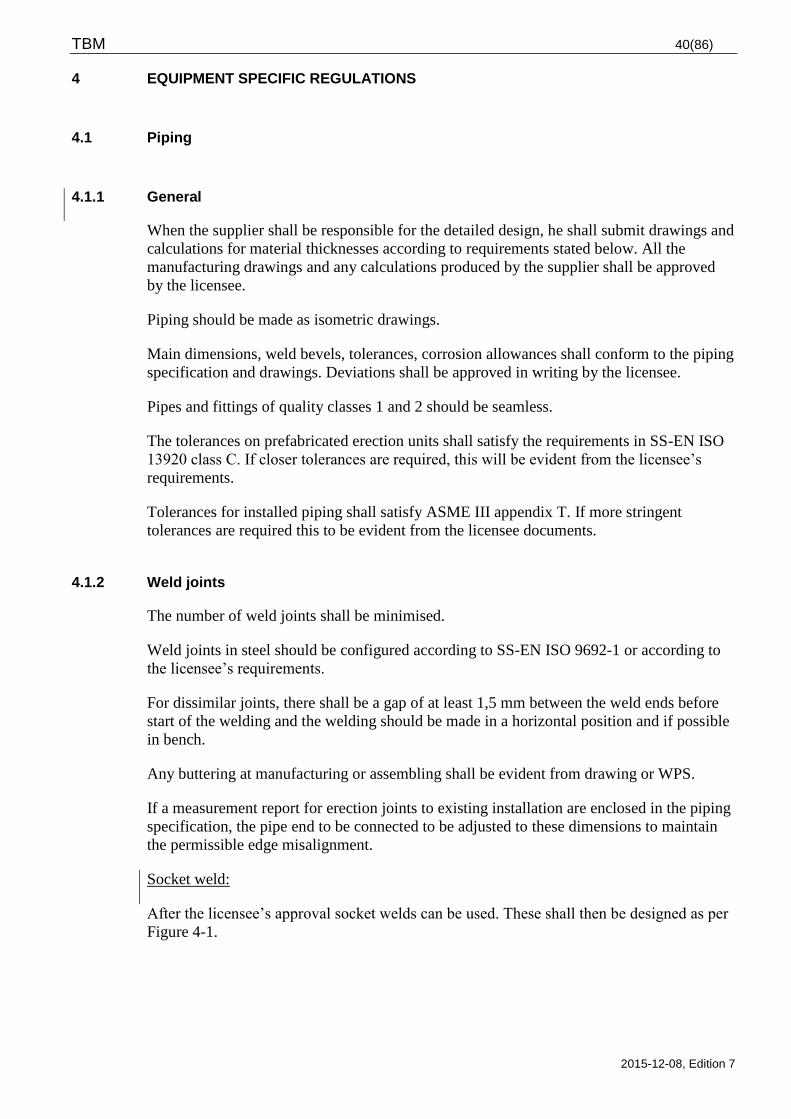
TBM 40(86)
2015-12-08, Edition 7
4 EQUIPMENT SPECIFIC REGULATIONS
4.1 Piping
4.1.1 General
When the supplier shall be responsible for the detailed design, he shall submit drawings and
calculations for material thicknesses according to requirements stated below. All the
manufacturing drawings and any calculations produced by the supplier shall be approved
by the licensee.
Piping should be made as isometric drawings.
Main dimensions, weld bevels, tolerances, corrosion allowances shall conform to the piping
specification and drawings. Deviations shall be approved in writing by the licensee.
Pipes and fittings of quality classes 1 and 2 should be seamless.
The tolerances on prefabricated erection units shall satisfy the requirements in SS-EN ISO
13920 class C. If closer tolerances are required, this will be evident from the licensee’s
requirements.
Tolerances for installed piping shall satisfy ASME III appendix T. If more stringent
tolerances are required this to be evident from the licensee documents.
4.1.2 Weld joints
The number of weld joints shall be minimised.
Weld joints in steel should be configured according to SS-EN ISO 9692-1 or according to
the licensee’s requirements.
For dissimilar joints, there shall be a gap of at least 1,5 mm between the weld ends before
start of the welding and the welding should be made in a horizontal position and if possible
in bench.
Any buttering at manufacturing or assembling shall be evident from drawing or WPS.
If a measurement report for erection joints to existing installation are enclosed in the piping
specification, the pipe end to be connected to be adjusted to these dimensions to maintain
the permissible edge misalignment.
Socket weld:
After the licensee’s approval socket welds can be used. These shall then be designed as per
Figure 4-1.
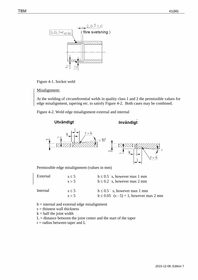
TBM 41(86)
2015-12-08, Edition 7
Figure 4-1. Socket weld
Misalignment:
At the welding of circumferential welds in quality class 1 and 2 the permissible values for
edge misalignment, tapering etc. to satisfy Figure 4-2. Both cases may be combined.
Figure 4-2. Weld edge misalignment external and internal
Permissible edge misalignment (values in mm)
External s 5 h 0.5 . s, however max 1 mm
s 5 h 0.2 . s, however max 2 mm
Internal s 5 h 0.5 . s, however max 1 mm
s 5 h 0.05 . (s - 5) + 1, however max 2 mm
h = internal and external edge misalignment
s = thinnest wall thickness
k = half the joint width
L = distance between the joint center and the start of the taper
r = radius between taper and L
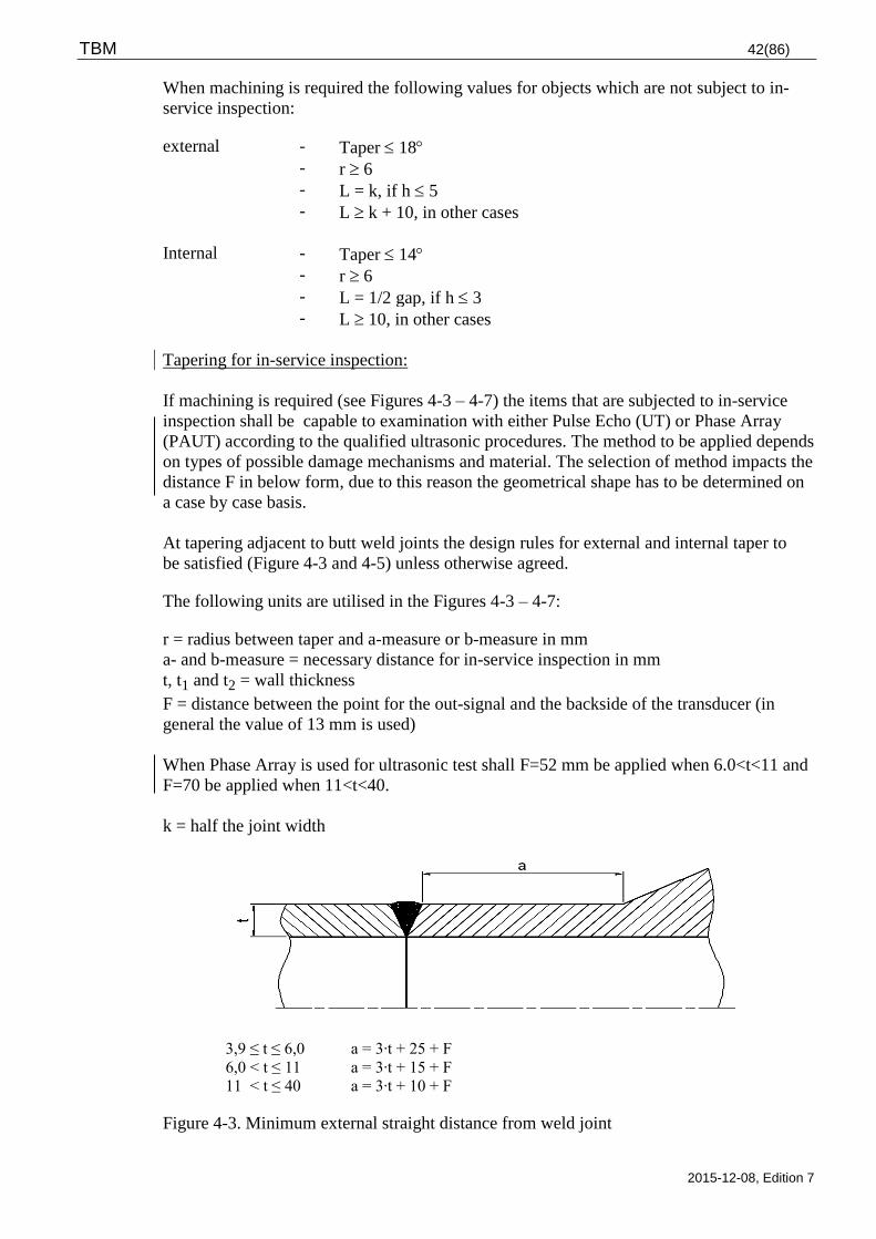
TBM 42(86)
2015-12-08, Edition 7
When machining is required the following values for objects which are not subject to in-
service inspection:
external - Taper 18
- r 6
- L = k, if h 5
- L k + 10, in other cases
Internal - Taper 14
- r 6
- L = 1/2 gap, if h 3
- L 10, in other cases
Tapering for in-service inspection:
If machining is required (see Figures 4-3 – 4-7) the items that are subjected to in-service
inspection shall be capable to examination with either Pulse Echo (UT) or Phase Array
(PAUT) according to the qualified ultrasonic procedures. The method to be applied depends
on types of possible damage mechanisms and material. The selection of method impacts the
distance F in below form, due to this reason the geometrical shape has to be determined on
a case by case basis.
At tapering adjacent to butt weld joints the design rules for external and internal taper to
be satisfied (Figure 4-3 and 4-5) unless otherwise agreed.
The following units are utilised in the Figures 4-3 – 4-7:
r = radius between taper and a-measure or b-measure in mm
a- and b-measure = necessary distance for in-service inspection in mm
t, t1 and t2 = wall thickness
F = distance between the point for the out-signal and the backside of the transducer (in
general the value of 13 mm is used)
When Phase Array is used for ultrasonic test shall F=52 mm be applied when 6.0<t<11 and
F=70 be applied when 11<t<40.
k = half the joint width
3,9 ≤ t ≤ 6,0 a = 3∙t + 25 + F
6,0 < t ≤ 11 a = 3∙t + 15 + F
11 < t ≤ 40 a = 3∙t + 10 + F
Figure 4-3. Minimum external straight distance from weld joint
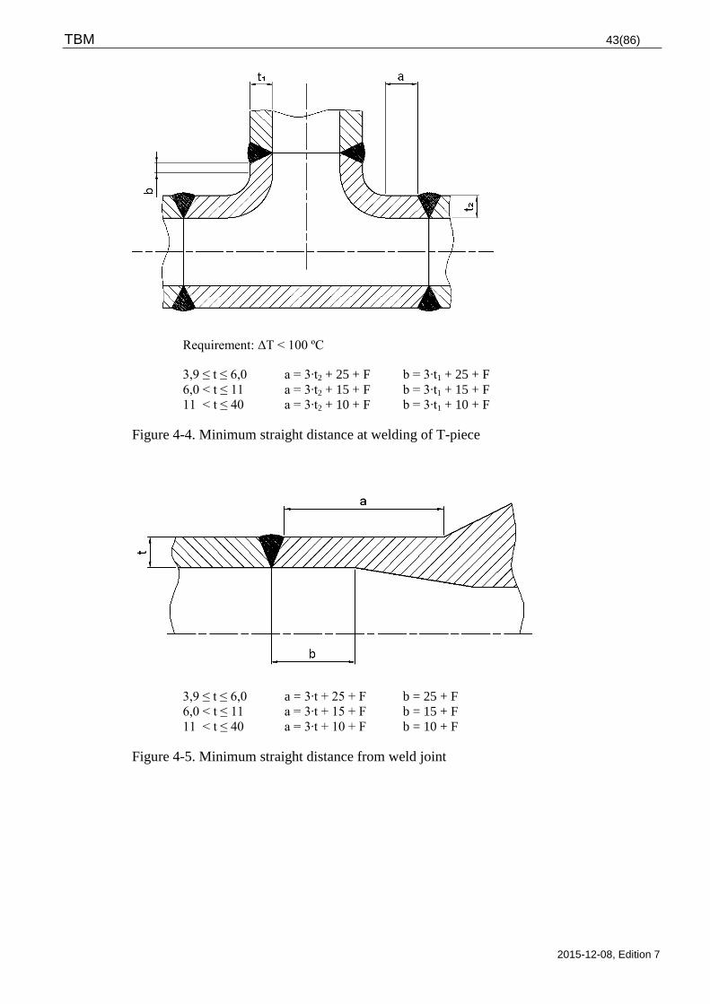
TBM 43(86)
2015-12-08, Edition 7
Requirement: ΔT < 100 ºC
3,9 ≤ t ≤ 6,0 a = 3∙t2 + 25 + F b = 3∙t1 + 25 + F
6,0 < t ≤ 11 a = 3∙t2 + 15 + F b = 3∙t1 + 15 + F
11 < t ≤ 40 a = 3∙t2 + 10 + F b = 3∙t1 + 10 + F
Figure 4-4. Minimum straight distance at welding of T-piece
3,9 ≤ t ≤ 6,0 a = 3∙t + 25 + F b = 25 + F
6,0 < t ≤ 11 a = 3∙t + 15 + F b = 15 + F
11 < t ≤ 40 a = 3∙t + 10 + F b = 10 + F
Figure 4-5. Minimum straight distance from weld joint
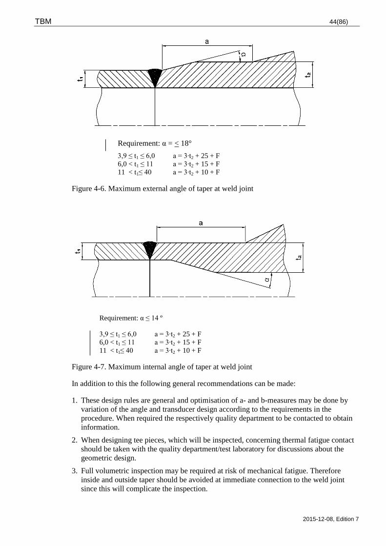
TBM 44(86)
2015-12-08, Edition 7
Requirement: α = < 18°
3,9 ≤ t1 ≤ 6,0 a = 3∙t2 + 25 + F
6,0 < t1 ≤ 11 a = 3∙t2 + 15 + F
11 < t1≤ 40 a = 3∙t2 + 10 + F
Figure 4-6. Maximum external angle of taper at weld joint
Requirement: α ≤ 14 º
3,9 ≤ t1 ≤ 6,0 a = 3∙t2 + 25 + F
6,0 < t1 ≤ 11 a = 3∙t2 + 15 + F
11 < t1≤ 40 a = 3∙t2 + 10 + F
Figure 4-7. Maximum internal angle of taper at weld joint
In addition to this the following general recommendations can be made:
1. These design rules are general and optimisation of a- and b-measures may be done by
variation of the angle and transducer design according to the requirements in the
procedure. When required the respectively quality department to be contacted to obtain
information.
2. When designing tee pieces, which will be inspected, concerning thermal fatigue contact
should be taken with the quality department/test laboratory for discussions about the
geometric design.
3. Full volumetric inspection may be required at risk of mechanical fatigue. Therefore
inside and outside taper should be avoided at immediate connection to the weld joint
since this will complicate the inspection.
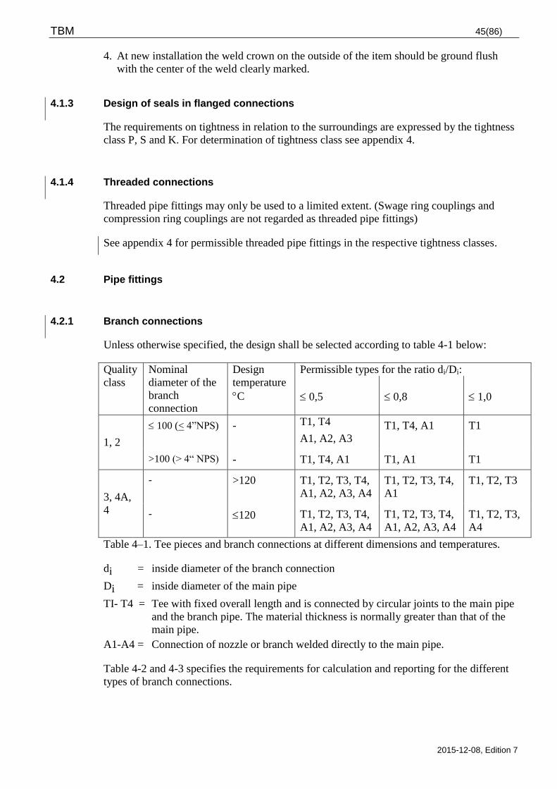
TBM 45(86)
2015-12-08, Edition 7
4. At new installation the weld crown on the outside of the item should be ground flush
with the center of the weld clearly marked.
4.1.3 Design of seals in flanged connections
The requirements on tightness in relation to the surroundings are expressed by the tightness
class P, S and K. For determination of tightness class see appendix 4.
4.1.4 Threaded connections
Threaded pipe fittings may only be used to a limited extent. (Swage ring couplings and
compression ring couplings are not regarded as threaded pipe fittings)
See appendix 4 for permissible threaded pipe fittings in the respective tightness classes.
4.2 Pipe fittings
4.2.1 Branch connections
Unless otherwise specified, the design shall be selected according to table 4-1 below:
Quality
class
Nominal
diameter of the
branch
connection
Design
temperature
C
Permissible types for the ratio di/Di:
0,5
0,8
1,0
1, 2
100 (< 4”NPS) - T1, T4
A1, A2, A3
T1, T4, A1 T1
>100 (> 4“ NPS) - T1, T4, A1 T1, A1 T1
3, 4A,
4
- >120 T1, T2, T3, T4,
A1, A2, A3, A4
T1, T2, T3, T4,
A1
T1, T2, T3
- 120 T1, T2, T3, T4,
A1, A2, A3, A4
T1, T2, T3, T4,
A1, A2, A3, A4
T1, T2, T3,
A4
Table 4–1. Tee pieces and branch connections at different dimensions and temperatures.
di = inside diameter of the branch connection
Di = inside diameter of the main pipe
TI- T4 = Tee with fixed overall length and is connected by circular joints to the main pipe
and the branch pipe. The material thickness is normally greater than that of the
main pipe.
A1-A4 = Connection of nozzle or branch welded directly to the main pipe.
Table 4-2 and 4-3 specifies the requirements for calculation and reporting for the different
types of branch connections.
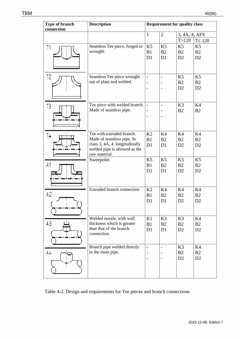
TBM 46(86)
2015-12-08, Edition 7
Type of branch
connection
Description Requirement for quality class
1 2 3, 4A, 4, AFS
T>120 T 120
Seamless Tee piece, forged or
wrought. K5
B1
D1
K5
B2
D1
K5
B2
D2
K5
B2
D2
Seamless Tee piece wrought
out of plate and welded.
-
-
-
-
-
-
K5
B2
D2
K5
B2
D2
Tee piece with welded branch.
Made of seamless pipe.
-
-
-
-
-
-
K3
B2
K4
B2
Tee with extruded branch.
Made of seamless pipe. In
class 3, 4A, 4 longitudinally
welded pipe is allowed as the
raw material.
K2
B1
D1
K4
B2
D1
K4
B2
D2
K4
B2
D2
Sweepolet K5
B1
D1
K5
B2
D1
K5
B2
D2
K5
B2
D2
Extruded branch connection
K2
B1
D1
K4
B2
D1
K4
B2
D2
K4
B2
D2
Welded nozzle, with wall
thickness which is greater
than that of the branch
connection.
K1
B1
D1
K3
B2
D1
K3
B2
D2
K4
B2
D2
Branch pipe welded directly
to the main pipe. -
-
-
-
-
-
K3
B2
D2
K4
B2
D2
Table 4-2. Design and requirements for Tee pieces and branch connections
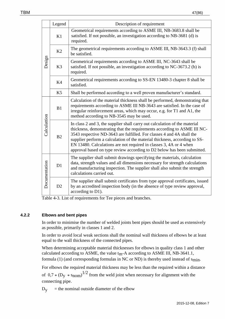
TBM 47(86)
2015-12-08, Edition 7
Legend Description of requirement
Des
ign
K1
Geometrical requirements according to ASME III, NB-3683.8 shall be
satisfied. If not possible, an investigation according to NB-3681 (d) is
required.
K2 The geometrical requirements according to ASME III, NB-3643.3 (f) shall
be satisfied.
K3
Geometrical requirements according to ASME III, NC-3643 shall be
satisfied. If not possible, an investigation according to NC-3673.2 (b) is
required.
K4 Geometrical requirements according to SS-EN 13480-3 chapter 8 shall be
satisfied.
K5 Shall be performed according to a well proven manufacturer’s standard.
Cal
cula
ttio
n
B1
Calculation of the material thickness shall be performed, demonstrating that
requirements according to ASME III NB-3643 are satisfied. In the case of
irregular reinforcement areas, which may occur, e.g. for T1 and A1, the
method according to NB-3545 may be used.
B2
In class 2 and 3, the supplier shall carry out calculation of the material
thickness, demonstrating that the requirements according to ASME III NC-
3543 respective ND-3643 are fulfilled. For classes 4 and 4A shall the
supplier perform a calculation of the material thickness, according to SS-
EN 13480. Calculations are not required in classes 3, 4A or 4 when
approval based on type review according to D2 below has been submitted.
Docu
men
tati
on
D1
The supplier shall submit drawings specifying the materials, calculation
data, strength values and all dimensions necessary for strength calculations
and manufacturing inspection. The supplier shall also submit the strength
calculations carried out.
D2
The supplier shall submit certificates from type approval certificates, issued
by an accredited inspection body (in the absence of type review approval,
according to D1).
Table 4-3. List of requirements for Tee pieces and branches.
4.2.2 Elbows and bent pipes
In order to minimise the number of welded joints bent pipes should be used as extensively
as possible, primarily in classes 1 and 2.
In order to avoid local weak sections shall the nominal wall thickness of elbows be at least
equal to the wall thickness of the connected pipes.
When determining acceptable material thicknesses for elbows in quality class 1 and other
calculated according to ASME, the value tm-A according to ASME III, NB-3641.1,
formula (1) (and corresponding formulas in NC or ND) is thereby used instead of smin.
For elbows the required material thickness may be less than the required within a distance
of 0,7 * (Dy * snom)1/2
from the weld joint when necessary for alignment with the
connecting pipe.
Dy = the nominal outside diameter of the elbow
TBM 48(86)
2015-12-08, Edition 7
Snom = the nominal material thickness of the elbow
The ovality of bent pipes and elbows shall in all sections be lower than or equal to 8 %. The
ovality is defined as:
O = ( Dmax - Dmin ) * 100 / Dy
where Dmax = largest outside diameter at a specific section
Dmin = smallest outside diameter at the same section
Dy = nominal outside diameter
The supplier shall submit drawings, specifying the materials and calculation data, and all
dimensions necessary for strength calculations and manufacturing inspection. The supplier
shall also submit strength calculations showing that the requirements are satisfied. This
documentation can be replaced by a type inspection certificate, issued by accredited
inspection body.
4.2.3 Reducers
Reducers are normally made as a conical transition piece with fillets. In the design work,
care shall be taken to ensure that the reducer will not cause an unnecessarily high exceeding
of stress in the piping. This is achieved by:
Large fillet radius. For reducers in class 1 the radius of the fillets should not fall below
0.1 * Dymax
Moderate cone angle. At least the conditions according to ASME III shall be fulfilled, i.e.
60 in class 1 respectively 70 in class 2, 3, 4A and 4
Cylindrical transition pieces to the connecting pipes. Compare the measurements L1 and
L2 in figure NB-3683.6-1 in ASME III.
Reducers without fillet with DN>50 / 2” NPS (large end) may only occur in piping in class
2, 3, 4A and 4 with calculation data not exceeding 2 MPa or 200 C.
Wall thickness calculation for reducers is performed according to SS-EN 13480 or ASME
III-NC.
The supplier shall submit drawings, specifying the materials and design data, and all
dimensions necessary for strength calculations and manufacturing inspection. The supplier
shall also submit strength calculations demonstrating that the requirements according to the
above mentioned calculation of smin are satisfied.
This documentation can be replaced with type inspection certificate issued by an accredited
inspection body.
4.2.4 Flanged connections
Primarily shall standard flanges of forged type be used, designed for butt welding to the
connecting pipe. Plain weld flanges and slip on flanges should only be employed in piping
of classes 3, 4A and 4. For such flanges shall the dimensions of welds and other parts
according to ASME III appendix XI Fig XI-3120-1 be considered and dimensions shall be
specified on the drawing.
TBM 49(86)
2015-12-08, Edition 7
In flanged connections of carbon steel, bolts and nuts shall be made of carbon steel.
Flanged connections of stainless steel may have bolts and nuts of stainless or galvanized
carbon steel, however, when choosing carbon steel bolts, the different coefficients of linear
expansion shall be regarded. Washers shall normally be used under nuts (in certain designs
under bolt heads or under both bolt heads and nuts).
The regulations for bolted joints and seals design are found in chapter 3.1.13 and 4.1.3.
Depending on the quality class, flanged connections are calculated according to the
requirements in ASME III or SS-EN 13480.
In cases when the pipe forces are unknown at sizing of flanged connections, 75 % at most
of the maximum allowed pressure should be used in order to obtain a reasonable margin for
pipe forces.
Pipe flanges (standard) shall be marked according to SS-EN 1092-1 or similar standard.
If the dimensions not complies to well recognised standard shall the supplier submit
drawings, specifying the materials, (including gasket) bolting forces and tightening torques
and dimensions necessary for strength calculations and manufacturing inspection. At
request the supplier shall also demonstrate calculations for bolting forces or tightening
torques.
4.2.5 Caps in pipe system
Caps will normally be deeply dished, i.e. either in the form of an ellipsoidal cap or as an
equal torispherical cap.
Flat caps >DN50/2”NPS may be used only for piping of quality class 2, 3, 4A and 4 with
design data not exceeding 2 MPa or 200ºC and also as temporary seals in other systems,
e.g. at pressure testing of a system section.
Caps in quality class 1 shall be calculated according to ASME III NB-3200.
Caps in quality class 2 shall be calculated according to ASME III NC-3224.
Caps in quality class 3 shall be calculated according to ASME III ND-3224 or ND-3325.
Caps in quality class 4A and 4 shall be calculated according to SS-EN 13480.
The supplier shall submit drawings, specifying the materials and design data, and all
dimensions necessary for strength calculations and manufacturing inspection. The supplier
shall also submit strength calculations demonstrating that the requirements are satisfied.
This documentation can be replaced with a type inspection certificate, issued by accredited
inspection body.
4.2.6 Welded lugs on steel pipes
Stop lugs shall be welded to pipes where axial fix points of supports, insulation etc. is
required. The recommended design of lugs and requirements and limitations for their use is
found in table 4-4. Lugs in quality class 1-3 shall be calculated with regard to mechanical
strength, this can be performed according to ASME III Appendix Y.
Where several lugs are installed at a fix point, they shall in principle be oriented according
to Figure 4-8. Care shall also be taken to ensure that lugs do not interfere with the bolts for
tightening of clamps.
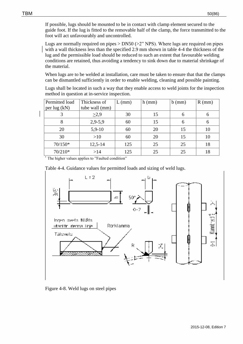
TBM 50(86)
2015-12-08, Edition 7
If possible, lugs should be mounted to be in contact with clamp element secured to the
guide foot. If the lug is fitted to the removable half of the clamp, the force transmitted to the
foot will act unfavourably and uncontrolled.
Lugs are normally required on pipes > DN50 (>2” NPS). Where lugs are required on pipes
with a wall thickness less than the specified 2.9 mm shown in table 4-4 the thickness of the
lug and the permissible load should be reduced to such an extent that favourable welding
conditions are retained, thus avoiding a tendency to sink down due to material shrinkage of
the material.
When lugs are to be welded at installation, care must be taken to ensure that that the clamps
can be dismantled sufficiently in order to enable welding, cleaning and possible painting.
Lugs shall be located in such a way that they enable access to weld joints for the inspection
method in question at in-service inspection.
Permitted load
per lug (kN)
Thickness of
tube wall (mm)
L (mm) h (mm) b (mm) R (mm)
3 >2,9 30 15 6 6
8 2,9-5,9 60 15 6 6
20 5,9-10 60 20 15 10
30 >10 60 20 15 10
70/150* 12,5-14 125 25 25 18
70/210* >14 125 25 25 18 The higher values applies to ”Faulted condition”
Table 4-4. Guidance values for permitted loads and sizing of weld lugs.
Figure 4-8. Weld lugs on steel pipes
TBM 51(86)
2015-12-08, Edition 7
4.2.7 Other pipe fittings
Other pipe fittings not covered by chapter 4.2.2 to 4.2.6 shall be designed, calculated and
documented according to similar principles. In doubtful cases, the licensee shall be
contacted for determining detailed requirements.
4.3 Valves
4.3.1 Introduction
This TBM part contains the requirements for valves of quality class 1, 2, 3, 4A and 4.
Detailed data for the respective valves are given in the valve specification according to
form TSM 102-104 (appendix 5).
4.3.2 Material restrictions
4.3.2.1 Material for valve bodies
At the use of stainless castings for valve bodies limitations according to chapter 3.1.8
applies. Stainless valves in quality class 1 and 2 shall be manufactured from forged
material.
Duplex stainless steel shall have a molybdenum content of minimum 3%. The composition
shall in addition satisfy the PRE criteria (Pitting Resistance Equivalent) > 37, whereas PRE
is calculated according to the following formula: PRE = Cr+3,3xMo+16xN.
4.3.2.2 Material for internal parts
The chromium (Cr) content shall be >12 % in martensitic stainless steel valve spindles. The
hardness of valve spindles of tempered martensitic steel must not exceed 300 HV.
For systems in contact with reactor media where the water is not first passing an ion
exchanger globe, seat or other internal parts must not consist of or be lined with alloys with
a cobalt content exceeding 0,20%. To achieve an effective hard facing in valve (globe and
seat) a slightly higher cobalt content may be accepted, see chapter 3.1.1
For other applications may however cobalt based alloys be used.
Supplier of globe, seat or other internals shall specify the relevant function data for the
application in question, including references for materials at friction- and sealing surfaces.
4.3.2.3 Gasket material – stuffing box packing
In stuffing boxes expanded graphite shall normally be used unless otherwise specified by
the licensee. For applications where high radiation doses can be expected shall pure
expanded graphite be used.
Graphite may however not be used for systems in contact with salt water since this
increases the risk of galvanic corrosion in adjacent equipment. PTFE packing shall be used
in valves for salt water.
TBM 52(86)
2015-12-08, Edition 7
The total in water leachable content at 100°C of organically and inorganically bonded
chlorides and fluorides, sulphate and antimony must not exceed 150 mg per kg and for
gaskets of pure graphite 50 mg per kg.
4.3.2.4 Lubricants
Sulphuric lubricants e.g. molybdenum disulphide must not be used in austenitic stainless
valves in humid environment and temperatures exceeding 100° C. Graphite based or
graphite nickel based lubricants shall primarily be used. Lubricants used must be classified,
approved and registered in the chemicals data base of the respective plant. For calculation
of compression force in bolted connections, lubricants friction value to be specified.
4.3.3 Design and calculation
4.3.3.1 General design requirements
The licensees can define the conditions of the valve application in one of the forms TSM
102-104 and the supplier shall adopt his design to satisfy the data specified in the form and
be responsible for the interaction between actuator and valve.
Unless otherwise specified shall bellows for bellow seal shall be capable of withstanding
5000 cycles at operation temperature (max 10 % break probability).
Cv-, K v- or z-values according to SS-EN 1267, SS-EN 60534-1, SS-EN 60534-2-1,
VDI/VDE 2173 or ISA S 75.01 shall be reported. The value shall be specified with
dimension.
Valve characteristics shall be reported.
The supplier shall specify the opening and closing torque for motor operated valves at all
applicable operation- and accident situations used at the dimensioning of the valve.
Additionally, the highest permitted torque (at failing switch) to be specified for opening as
well as closing.
All valves shall be designed to facilitate maintenance and dismantling. Particular care shall
be given to all components, which directly or indirectly affect the reliability of the valve.
Valves weighing over 25 kilos shall be furnished with lifting eye bolts and lifting aspects to
be regarded.
The valve including support or similar shall be designed without crevices and pockets to
minimise the risk of corrosion and to facilitate application of an effective corrosion
protection e.g. painting, galvanising or rubber-lining.
Valves, which can be subjected to in-service inspection, shall be of a geometric shape and
surface finish that the welded joints can be completely volumetrically tested. Only when
this is obviously unrealistic, it may be assumed that the volumetric test will be replaced
with other method, which in that case shall be specified.
Areas in valve bodies that can be subjected to corrosion or erosion attacks shall be possible
to measure the material thickness from the outside. The licensee specifies the valves
comprised by this requirement.
All carbon steel surfaces in contact with medium shall be provided with a corrosion
allowance of at least 1 mm, unless otherwise stated in the valve specification.
TBM 53(86)
2015-12-08, Edition 7
Valve bodies shall be of such strength that the connecting pipes, and not the valve itself,
will be the limiting factor for the loads in the piping. To achieve this, the following
conditions shall be satisfied:
Except for weld ends the cross-sectional area and the section module of each cross
section perpendicular to the direction of flow shall be at least 25 % greater than the
corresponding values for the connected pipes
The yield strength of the material in the valve body shall, if possible, be at least as large
as that of the material of the connected pipes. If the yield strength of the of the valve
body material is lower than that of the pipe material, the necessary section module and
cross-sectional area mentioned above shall be multiplied by the ratio of the pipe material
yield strength to valve material yield strength
The yield strength of the weld ends shall be at least as high as that of the connected pipes
Any deviations from the above conditions must be evident in the tender documentation.
For valves in quality class 1 the Sm -value shall be used instead of the yield strength.
All valves provided with stems with the exception of safety valves shall normally be
capable of being mounted in any position. Any limitation in this respect must always be
stated in the quotation.
Threaded joints, important for the function of the valve, shall normally be provided with a
device for locking the thread mechanically. This device must not increase the risk of galling
and shall be designed to always permit re-use of the threaded joint. The risk of galling shall
generally be observed and the principles e.g. differences in hardness that are applied shall
be clearly defined.
The direction of rotation for a hand wheel or wheel on an actuator shall always be
clockwise to shut the valve. This applies also if the valve is link controlled.
If the function of the valve is dependant on the direction of flow this shall be evident from a
permanent marking on the valve body, by means of an arrow or similar.
Lantern rings and spacer rings in double stuffing boxes shall be made of stainless steel or
carbon/carbon graphite. Selected material shall be accepted by the licensee. Threaded holes
for an extraction tool shall always be provided.
Pneumatically actuated valves shall always back-seat in the fully open position, unless
otherwise specified.
Valves shall be designed to prevent harmful vibrations in globe and stem.
Isolation valves shall be possible to equip with a continuous, mechanical position indicator
unless the design of the valve is such that the valve position is evident. Open or closed
valve shall always be possible to read. It shall in addition be possible to equip the valve
with micro switches in “open“ or “closed“ position. The devices for position indication
shall be robust in order to obtain distinct indications.
Valves with stuffing box gland or stuffing box nut shall include provision for after-
tightening the stuffing box packing without the need for dismantling parts of the valve or
the actuator. Replacement of stuffing box packing shall be possible without dismantling the
valve bonnet, actuator etc.
Surface finish for valve stems of this part of the gland shall be so fine (usually Ra 0.4 m
for graphite tightening) that the wear is minimised on the stuffing box rings and not have
machining marks perpendicular to the direction of the stem movement.
TBM 54(86)
2015-12-08, Edition 7
4.3.3.2 Connections
Connections shall be adapted to the connecting pipes. The sizes of connecting pipes are
specified in the valve specification.
Location of nozzles for drain, over pressure protection and tightness testing to be separately
specified.
For flanged connections the following applies:
For quality classes 1 and 2 standard flanges must be of at least pressure class PN 16/150#
even if the design pressure is lower. For quality classes 3 and 4A pressure class PN
10/150# is correspondingly applicable.
If the design temperature exceeds 200°C shall bolts and both the mating flanges be made
of material with the same coefficient of linear expansion. However, carbon steel bolts
may be used in stainless flanges if a suitable compensation is arranged for the difference
in the coefficient of linear expansion.
The risk for unloading (leakage) or overloading of gaskets and bolts shall be particularly
regarded at flange joints subjected to temperature changes
Washers shall normally be used under nuts. (In certain designs under bolt heads or under
both bolt heads and nuts)
Regulations for bolted joints are specified in chapter 3.1.13.
4.3.3.3 Design of seals
The tightness requirement in relation to the surroundings is expressed in the valve
specification by stating the tightness class. For determination of tightness class see
appendix 4.
Gland packing:
Single stuffing box shall be utilised unless any specific requirements for leakage detection.
Bellow sealed stem shall be utilised whenever required due to the media e.g. hydrogen gas.
Double seals with intermediate drainage shall be avoided. When there are no other possible
technical resolutions to fulfil possible requirements for leakage detection may however
double seals with intermediate drainage be accepted.
Each seal of double configuration shall be capable of maintaining the sealing function on its
own. The drainage between double seals is only required to indicate incipient leakage.
Stuffing box drainage must not be connected internally in the valve with the bonnet flange
drainage.
Where technically suitable, all valves with an axially movable stem should be provided
with back-seating to prevent leakage into the stuffing box when the valve is fully open.
The back-seating shall be of the same quality regarding the tightness etc. as the sealing
surfaces of the closing device.
TBM 55(86)
2015-12-08, Edition 7
4.3.3.4 Strength calculations
The design data and loads required for design and strength calculations of valves are
specified by the purchaser in the valve specification and its appendices.
All calculations shall be reported in a clear and legible manner with sources, references,
drawings, part numbers etc. The documentation shall be reviewable. Earlier performed
calculations demonstrating that the valve is acceptable for loads that are higher than those
specified may be used.
Valves with large eccentric mass must be reviewed regarding loads caused due to the
eccentricity.
Valve parts shall be divided into categories 1, 2, 3, 4 and 5 according to the detailed
instructions below:
Pressure retaining casing belong to category 1, i. e. body, bonnet, globe and parts welded
to the valve, such as nozzles etc.
Category 2 includes pressure-retaining threaded joints, i. e. generally joints between
valve bodies and bonnets or between valve bodies and covers
Category 3 includes internal and external valve fittings, primarily load bearing without
therefore belonging to the pressure-retaining shell, e.g. stem (in ball valves also the
trunnion), load bearing connection between stem and the disc (gate), load bearing ring
for pressure sealing cover, guide for gate, seat ring (if it is primarily load bearing), gland
flange and gland bolts
Category 4 includes springs of importance for the function of the valve e.g. spring in
pneumatic actuator, return springs in valves media activated valves and springs for seat
rings in ball valves
Category 5 includes the yoke with fastening equipment.
At strength calculation of motor operated valves shall category 1 and 2 be designed against
actuation forces at failing torque/limit switch at 110% power supply (breakdown torque /
stall torque). This needs not to be combined with other accident loads but with loads at
design pressure and design temperature.
4.3.3.5 Design of valves in quality class 1
Loads within the limits corresponding to “Design Loadings“ and “Level A“ and “Level B“
according to ASME III NB-3220 shall not influence the function and tightness of a valve.
Calculations shall be performed for transient loads according to ASME III NB-3500 or NB-
3200.
Category 1 parts shall satisfy applicable parts of ASME III NB-3500.
The Sm-value shall be based on ASME II D Appendix 2.
At determining the minimum wall thickness according to ASME III NB-3543, the material
used shall be compared with an "ASME material" with equivalent strength values.
Category 2 parts shall fulfil ASME III NB-3546.1.
Permissible bolt stress for “Design Conditions“ and thereby necessary bolt area according
to ASME III XI-3222 deviates from European practice and in cases where this could cause
extensive modifications of valve types normally used, it can be accepted that Sa and Sb
according to ASME XI-3222 is replaced by other recognised bolt stress referring to code or
TBM 56(86)
2015-12-08, Edition 7
standard accepted by the licensee. Sa in ASME XI-3223, equation (4), shall thereby
naturally also be replaced.
Calculation of the necessary bolt forces and tightening torque for bolted joints in category 2
shall be included in the calculation report.
For parts of category 3 an analysis of primary stresses shall demonstrate that the conditions
in ASME III NB-3546 are satisfied with respect to all mechanical loads. Section loads are
determined with simple equilibrium relationship. The stresses are calculated with
elementary formulas for normal or bend stresses. Local stresses caused by contact pressure
in e.g. seat surfaces need not thus be reported.
For parts of categories 4 and 5, an analysis shall be reported to demonstrate that they are
adequate for the application in question. The analysis shall include an evaluation of
overload and fatigue risks.
4.3.3.6 Design of valves in quality classes 2 or 3
For valves in quality class 2 and 3 shall calculations or other documentation be presented to
verify that the dimensions of parts of category 1 and 2 are acceptable with regard to design
data. ASME Section III, NB-3543 and NB-3545.1 or other acceptable, verified method
should be used for calculations. Other documentation may consist of, e.g. results from
stress measurements.
Flange joints shall be evaluated against ASME III-NC, ASME III-ND or SS-EN 13480.
For valves in quality class 2 and 3, shall also a verification be perform to demonstrate that
the parts of categories 3, 4 and 5 are acceptable for the application in question.
4.3.3.7 Design of valves in quality classes 4A and 4
For valves shall dimensions of parts of category 1 and 2 be verified according to SS-EN
12516 with respect taken to design data. As an alternative may any of the two calculation
methods specified for quality class 2 and 3 be used. Other documentation may consist of
e.g. results from stress measurements.
Flange joints shall be evaluated against ASME III-NC, ASME III-ND or SS-EN 13480.
4.3.4 Manufacturing
Valves shall be marked in accordance with SS-EN 19. Safety valves shall however be
marked according to SS-EN ISO-4126-1. If required by the purchase order the valves shall
also be marked with component numbers specified by the licensee.
Pressure-retaining valve parts shall be marked with serial number or the like to enable
identification against the inspection documentation.
The valve body shall be permanently marked with an arrow or similar indicating the flow
direction if the function of the valve is dependant of the direction of flow.
TBM 57(86)
2015-12-08, Edition 7
4.3.5 Documentation
4.3.5.1 Documentation required at tendering
The documentation shall at least include information of:
General design and installation dimensions
Materials (designation according to standard)
Pressure rating
Operation and design data
Cv -, kv-, or z-values according to 4.3.3.1
Control characteristics
Total weight and center of gravity with and without actuators
Program for cleaning, corrosion protection and painting
Inadmissible erection positions
Direction of flow
Recommended spare parts
Material and type of gaskets
Requirements related to maintenance requirements such as periodic replacement,
recommended maintenance, arrangements for installation/dismantling etc.
The quotation documents shall clearly state if the offered valve in any respect deviates from
the requirements in the valve specification and TBM.
4.3.5.2 Documentation required before manufacturing
The required manufacturing documentation that shall be approved by the licensee is
specified in KBM.
The below data shall be sent to the licensee for approval:
Final pressure drop
Actuator specifications
Calculations
The drawing package shall in addition to the data prescribed in the relevant codes and
standards as a minimum requirement contain the below listed data:
Plant name and the licensee’s component designation
Assembly drawing and detailed drawings with reference to a valid inspection plan,
calculations, WPS etc.
Parts list with material designations according to applicable standard
Procedures for welding, forming, heat treatment, etc.
Dimensions of connections
TBM 58(86)
2015-12-08, Edition 7
Dimensions necessary for calculations (wall thicknesses and flange thicknesses, internal
dimensions, radii, dimensions of nozzles and bolts, joint shapes, weld joint efficiency
factors for butt welds, etc.)
Mass and center of gravity for valve including actuator
Pressure rating
Design data (design pressure and design temperature)
Allowance for corrosion and abrasion
Pressure for pressure testing
Stuffing box dimensions
Flow direction arrow
Back seating design
Quality class, tightness class
Required bolt forces and tightening force
All dimensions necessary for normal service
Interlocks
Corrosion protection.
4.3.5.3 Final documentation
Technical component documentation shall contain drawings with information according to
the above. It shall also contain procedures for operation and maintenance in the Swedish
language, or, as an exception in the English language. These procedures shall include data
such as maintenance intervals, lubrication instructions and overhaul instructions.
For control valves and medium controlled valves shall a general function description be
enclosed.
Other final documentation as per KBM.
TBM 59(86)
2015-12-08, Edition 7
4.4 Pumps
4.4.1 Introduction
This TBM part contains the requirements for pumps of quality classes 2, 3, 4A and 4.
Detailed data can be found in a specific pump specification, TSM 106, (appendix 5).
4.4.2 Material restrictions
4.4.2.1 Material for pump casings
Limitations according to chapter 3.1.8 applies for the use of stainless castings in pump
casings.
4.4.2.2 Internal parts
The chromium content shall be >12 % in pump shafts of stainless martensitic steel. The
hardness must not exceed 300 HV in pump parts of quenched and tempered martensitic
stainless steel.
Duplex stainless steel shall have a molybdenum content of minimum 3%. The composition
shall in addition satisfy the PRE criteria (Pitting Resistance Equivalent) > 37, whereas PRE
is calculated according to the following formula: PRE = Cr+3,3xMo+16xN.
4.4.2.3 Material for shaft seals
Material in mechanical pump shaft seals for pumps in quality class 2, 3 and 4a shall be
selected in agreement with the licensee.
For rotating plane seals the sealing surfaces must not contain antimony.
4.4.2.4 Gasket material – Stuffing box packing
Stuffing boxes or gaskets containing graphite are not approved for use in sea water systems.
Static rotating plane seals shall primary be used as per SS-EN ISO 21049.
The total in water leachable content at 100°C of organically and inorganically bonded
chloride and fluoride must not exceed 150 mg per kg and for gaskets of pure graphite 50
mg per kg.
4.4.2.5 Lubricants
Graphite based or nickel graphite based lubricants shall primarily be used. Graphite based
lubricants may however not be used in systems that can be in contact with sea water.
Sulphuric lubricants like e.g. molybdenum disulphide must not be used in austenitic
stainless steel pumps in humid environment and temperatures exceeding 100°C.
Lubricants used must be classified, approved and registered in the chemicals data base of
the respective plant.
TBM 60(86)
2015-12-08, Edition 7
4.4.3 Design and calculation
4.4.3.1 General design criteria
Applicable parts of the standards EN-ISO 13709:2003, SS-EN ISO 21049 and SS-EN 9906
shall be used.
The supplier shall adapt his design so the type of motor types and shaft seals, proposed by
the licensee, can be used.
Couplings for force transmitting shall primary be of the type membrane coupling and
satisfy the standard ISO 10441:2007.
All pumps shall be designed to facilitate maintenance and dismantling. Great care shall be
devoted to all details, which, directly or indirectly, affect the reliability of the pump. It shall
be observed that maintenance normally can be carried out once a year only.
Components with a weight exceeding 25 kg shall be provided with lifting lugs or other
suitable device to facilitate repairs and maintenance.
The direction of rotation shall be marked on the pump casing and, when considered
necessary, the flow direction shall be marked with an arrow on the pump casing.
Shaft seals shall to applicable parts be designed according to SS-EN ISO 21049.
Roller and slide bearings shall be designed for a service life exceeding 50 000 hours
operation.
The critical rotation speed shall exceed 125 % of normal rotation speed.
The pump shall be capable of remain on standby, while filled with liquid, without being
damaged.
When stated in the pump specification that the medium is radioactive, the pump shall be
designed to be easily decontaminated. Pockets collecting particles of debris shall as far as
possible be avoided.
The pump performance curve shall be stable from zero flow to maximum flow to applicable
parts as per ISO 9906. Pumps specified for parallel operation shall be able to work together
with a similar pump, not necessary identical.
All carbon steel surfaces in contact with the medium shall be provided with a corrosion
allowance of minimum 1 mm, unless otherwise is stated in the pump specification.
4.4.3.2 Connections
The dimensions of the connecting pipes shall be specified in the pump specification. The
supplier shall perform and submit calculations, demonstrating the magnitude of the forces
and moments the connection nozzles may be subjected to. Requirements for bolted joints
are specified in chapter 3.1.13.
4.4.3.3 Sealing arrangements
The requirements for tightness in relation to the surroundings is expressed in the pump
specification by stating the tightness class. Shaft seal type for pumps in different tightness
TBM 61(86)
2015-12-08, Edition 7
classes are specified in the respective pump specification. For determination of tightness
class, see appendix 4.
4.4.3.4 Design calculations
The design data and loads required for design and strength calculations of pumps have been
specified by the licensee in the pump specification and its appendices.
All calculations shall be reported in a clear and legible manner, clearly showing sources,
references, drawings, part numbers etc.
For calculations in quality class 2 and 3 ASME III, NC-3400 or other recognized verified
method to be applied.
Flanged connections in quality class 2 and 3 shall be evaluated towards ASME III-NC and
ASME III-ND, in quality class 4 SS-EN 13480 to be used.
4.4.4 Vibrations and balancing
A pump unit – complete pump and motor fully installed at location shall be free from
resonances that may affect the operation. Freedom from resonances shall apply to the span
at +/- 20% from operation RPM, double operation RPM, blade passage speed and double
net frequency (100 Hz).
-For rigid rotors shall the critical RPM be higher than 125% of the highest RPM within the
operating RPM
For flexible rotors freedom of resonance is required within +25% and -15% from the
operating RPM .
Rotors and rotor parts shall be balanced according to SS-ISO 1940-1, whereas complete
rotor, i.e. pump unit, electrical motor or pump is balanced to G2,5, however, single rotor
parts are balanced to one class better, i.e. G1,0. Balancing is performed with half wedge as
per SS-ISO 8821.
If Cardan shaft is used at the balancing shall an index test be reported.
For pumps that are operated above the first critical RPM shall high RPM and low RPM
balancing be performed as per ISO 11342. Residual out of balancing criteria shall be
applied and it shall also apply to the operational RPM.
To enable field balancing there shall be a balancing plan accessible at the location of the
installed pump.
Measuring of vibrations and requirements regarding bearing vibrations in completely
installed unit within the permissible range of operation shall mainly comply to SS-ISO
10816 -7 category 1 zone A, however, maximum permitted 2,8 mm/s RMS. The
requirements shall apply for all three measuring directions (horizontally, vertically and
axially). The following highest vibration levels applies to installed pumps:
- Pumps > 200 kW: 2,8 mm/s RMS
- Pumps < 200 kW: 2,5 mm/s RMS
Electrical motor installed in the plant shall satisfy the vibration requirements as per SS-
ISO-10816-3, however, maximum 2,8 mm/s RMS, i.e. the following vibration levels for all
three measuring directions (horizontally, vertically and axially):
TBM 62(86)
2015-12-08, Edition 7
- Motors > 300 kW: rigid support maximum: 2,3 mm/s RMS and flexible support
maximum 2,8 mm/s RMS.
- Motors < 300 kW: rigid support maximum: 1,4 mm/s RMS and flexible support
maximum 2,3 mm/s RMS.
For electrical motors < 15kW applies requirements as per SS-ISO-10816-1, the requirements
for such motors according to table B1 zone A/B is maximum 1,12 mm/s RMS.
The requirement for low RPM complete pump units, e.g. main coolant pumps is maximum 1
mm/s RMS.
The supplier shall be capable to present protocol from the balancing.
4.4.5 Manufacturing
All pumps shall be marked with a component number specified by the licensee.
Pressure-retaining pump components shall be marked with serial number or similar to
enable identification against the inspection documentation.
The direction of rotation shall be permanently marked on the pump casing if considered
necessary, the direction of flow shall be marked with an arrow on the pump casing.
4.4.6 Documentation
4.4.6.1 Documentation required at tendering
The documentation shall contain at least the following:
General design and installation dimensions
Materials (designation according to standard)
Pressure rating
Operation- and/or design data
Permissible forces and moments on connections
Total weight with and without medium
Program for cleaning, corrosion protection and painting
Recommended spare parts
A pump characteristic curve showing flow, developed head, shaft efficiency, required
NPSH, efficiency, rotation speed for all impeller diameters
Limiting span for operation
The required cooling or flushing water flow
Starting torque curve with open and closed valve
Number of pistons, cylinder diameter and piston stroke for piston pumps
Design of shaft seal
Requirements related to maintenance such as periodic replacement, recommended
maintenance, arrangements for installation/dismantling etc.
TBM 63(86)
2015-12-08, Edition 7
The quotation documents shall clearly state if the offered pump in some respect deviates
from the requirements in the pump specification and TBM.
4.4.6.2 Documentation required before manufacturing
The below component data shall be sent to the licensee for approval:
Instructions for operational and preventative maintenance
The drawings shall as a minimum requirement contain the following data:
The name of the plant and the licensees component designation
General arrangement drawing and detail drawings with reference to valid inspection plan
Parts list with material designations according to applicable standards
Procedures for welding, forming, heat treatment, etc.
Over all dimensions
Dimensions of connections
Other dimensions required for calculations (thicknesses of walls and flanges, internal
dimensions, radii, branch and bolt sizes, joint shapes, welding joint efficiency factor for
butt welds, etc.)
Pressure rating and design data
Margin for corrosion and abrasion
Corrosion protection
Pump curve for the applicable impeller diameter and final motor speed. The curve shall
show the developed head, power, efficiency and NPSH as function of the volumetric
flow. The curve shall also state expected data for these parameters at maximum and
minimum impeller diameter.
For pumps controlled through the RPM shall also a mussel diagram be provided to the
licensee. The diagram shall cover the RPM span that the pump will operate within steps
(as a proposal in 200 RPM steps ). A mussel diagram is regarded as a diagram that
shows the developed head, power and efficiency as a function of the volumetric flow.
Critical speed
Instructions for lifting and transport
Installation instructions including data of grouting procedures
Quality class, tightness class
Permissible forces and bending moments on nozzles
Required bolt forces and tightening torques for bolts
Design and dimension of shaft seal
Load on the foundation
Pressure for pressure testing
TBM 64(86)
2015-12-08, Edition 7
4.4.6.3 Final documentation
Technical component documentation shall contain drawings with data according to above.
It shall also contain procedures for operation and maintenance in the Swedish language, or,
as an exception in the English language. These procedures shall include information such as
maintenance intervals, lubrication instructions and overhaul instructions.
Other final documentation according to KBM.
TBM 65(86)
2015-12-08, Edition 7
4.5 Heat Exchangers
4.5.1 Introduction
This TBM part contains the requirements for heat exchangers of quality classes 1, 2, 3, 4A
and 4. Detailed data can be evident in a specific heat exchanger specification, TSM 107
(appendix 5).
4.5.2 Material restrictions
For austenitic stainless steel plates and tubes in heat exchangers for salt water, material with
a molybdenum content of at least 6 % shall be chosen.
Duplex stainless steels shall have a molybdenum content of at least 3%. The composition
shall in addition also satisfy the criteria PRE (Pitting Resistance Equivalent) > 37, whilst
PRE is calculated according to the following formula: PRE = Cr+3,3×Mo+16×N.
For all parts in contact with primary water the cobalt content shall be < 0,05 %.
Cold bendt tubes shall be solution heat treated when the mean bending radius is < 16 * Dy
if they shall be used with primary water at an operating temperature > 100º C.
4.5.3 Design and Calculations
4.5.3.1 General design requirements
Heat exchangers of quality classes 1, 2 or 3 shall be designed to allow for in-service
inspection. The number of pressure-retaining welds shall thus be the minimum possible and
they shall be of such design that volumetric inspection, primarily by methods such as
ultrasonic examination can be performed without the disturbing effect of geometries or
other discontinuities.
The heat exchanger including the support and foundation shall be designed without crevices
and pockets to minimise the risk for corrosion and to facilitate application of an effective
corrosion protection, e.g. painting, galvanising or rubber-lining.
Tube inlets in heat exchangers shall be designed so that the least possible disturbance of the
flow on the inlet side is achieved.
In order to avoid leakage or crevice corrosion at roll expanding of tubes, heat exchangers
designed with tubes rolled in the tube plate shall have seamless tubes, alternatively,
longitudinally welded tubes with ground welds.
Tube heat exchangers, cooled with salt water shall be provided with straight tubes and
heads made of titanium or rubber-lined end sections. Heat exchangers with tubes made of
copper alloys shall be provided with sacrificial anodes or anodes with impressed current in
all channel heads. Good electrical contact between anodes and tube plate is necessary.
Rubber-lining shall comprise all connecting nozzles and flange surfaces.
Tube heat exchangers shall be designed to enable simple and quick stop of tube leakage by
plugging.
Dismantling of the head sections in a tube heat exchanger shall be possible without the tube
bundle being deformed or moved out of its position. In addition it shall be possible to
TBM 66(86)
2015-12-08, Edition 7
replace individual tubes or a whole bundle of tubes without damage to tubes, baffles or
support plates.
Expansion bellows shall be of proven design, without guide tubes. Expansion bellows are
not accepted in quality class 1.
Components with a weight exceeding 25 kg shall be provided with lifting lugs or other
suitable device for facilitating repairs and maintenance.
All wetted carbon steel surfaces except tubes, shall be provided with a corrosion allowance
of at least 1 mm, unless otherwise stated in the heat exchanger specification.
Vibrations expected to reduce the life span of the heat exchanger shall not occur during
operation even if the specified flow and/or the temperature is exceeded by 25 %.
The ovality of bent tubes must not exceed 8 %.
The ovality is defined as (Dmax-Dmin) * 100 / Do
Dmax = maximum outside diameter after bending
Dmin = minimum outside diameter after bending
Do = nominal outside diameter
The minimum wall thickness in the bend must not be less than the required to meet the
strength requirements.
4.5.3.2 Connections
Connections shall be adapted to connecting pipe. The dimensions of the connecting pipe
work are specified in the heat exchanger specification. For quality class 1 they shall be
designed according to ASME III fig NB-4250, unless otherwise specified, and at least be
sized with regard to ASME III NB-3330.
Location of nozzles for leak testing, drainage, tightness testing and cleaning are specified
separately.
Annular or flat reinforcements are not permitted in quality class 1.
The nozzles shall be designed with regard to the forces and moments from connecting
pipes. If these forces are not specified, the nozzles shall have at least the capacity of the
connecting pipes.
For flanged connections the following applies:
Flanges should be of butt weld design. However, slip-on flanges may be used after the
licensee’s approval
For heat exchangers of quality classes 1 and 2, standard flanges must be at least of
pressure class PN 16/150# even if the calculation pressure is lower. For quality classes 3
and 4A, the pressure class PN 10/150# is correspondingly applicable
Heat exchangers of quality classes 1 and 2 shall have forged flanges
If the design temperature exceeds 200° C bolts and the both mating flanges shall be made
of material with the same coefficient of linear expansion. However, carbon steel bolts
may be used in stainless flanges if a suitable compensation is arranged for the difference
in the coefficient of linear expansion
TBM 67(86)
2015-12-08, Edition 7
Washers shall normally be used under nuts. (In certain designs under bolt heads or under
both bolt heads and nuts).
For flanged connections subjected to temperature changes, the risk for unloading
(leakage) or overloading of gaskets and bolts shall be particularly regarded
Requirements for bolted connections are specified in chapter 3.1.13.
4.5.3.3 Sealing arrangements
The tightness requirements for flanges, man holes, water- and channel heads in relation to
the surrounding are specified in the heat exchanger specification by stating the tightness
class. For determination of tightness class see appendix 4.
4.5.3.4 Strength calculations
The design data and loads required for design and strength calculations of heat exchangers
have been specified by the licensee in the heat exchanger specification and its appendices.
All calculations shall be reported in a clear and legible manner, with sources, references,
drawings, part numbers etc. accurately specified. The documentation shall be reviewable.
Earlier performed calculations, showing that the heat exchanger is acceptable for loads that
are higher than those specified, may be used.
Heat exchangers shall be dimensioned according to applicable codes specified in chapter
3.2.
Pressure-retaining bolted joints shall satisfy ASME III NB 3230. However, allowed bolt
tension for “Design Conditions“ and thereby necessary bolt area according to ASME III
XI-3222 deviates from European praxis. In the cases where this would require extensive
modifications, it can be accepted that Sa and Sb according to XI-3222 is replaced by other
acknowledged permitted bolt tension with reference to code or standard after permission
from the licensee. Sa in ASME III XI-3222, equation (4), shall then thereby be replaced.
The Sm value for bolts shall be based on ASME II D Appendix 2.
Calculations for required bolt forces and tightening torque for bolted joints shall be
included the calculation report.
Calculations for transient loads shall be carried out according to ASME III NB-3200.
4.5.4 Manufacturing
4.5.4.1 General requirements at manufacturing
Tubes must not be cleaned by steam blowing. Mechanical cleaning of tubes shall be
performed with method avoiding damages to the tubes.
When dismantling the heat exchanger at e.g. manufacturing or transport, new seals shall be
used at the subsequent assembly.
Heat exchanger tubes must not be joined by welding.
TBM 68(86)
2015-12-08, Edition 7
Cold working of tubes during rolling operations shall be restricted to the minimum
possible, max 10 %. Production tests shall be carried out and inspected according to
procedure drawn up by the manufacturer and approved by the licensee.
At delivery of tube heat exchangers spare tubes shall always be delivered for future testing.
The tubes shall be chosen from the same batch as those used in the heat exchanger.
4.5.5 Documentation
4.5.5.1 Documentation required on tendering
The documentation shall contain at least the following data:
General design and installation dimensions and over all dimensions and space
requirements for service and installation
All dimensions necessary for flow and thermodynamic calculations
Materials (designation according to applicable standard)
Program for cleaning, corrosion protection and painting
Total weight with and without medium
Directions of flow
Maintenance related requirements such as periodic replacement, recommended
maintenance, arrangements for assembly / disassembly etc.
The quotation documents shall clearly state if the offered heat exchanger in some respect
deviates from the requirements in the specification and TBM.
4.5.5.2 Documentation required before manufacturing
The below equipment data shall be sent to the licensee for approval:
Final pressure drop
The drawings shall at least include the data stated below in addition to the information
required in relevant codes and standards:
The name of the plant and the licensees component designation
General arrangement drawing and detail drawings with reference to valid inspection plan
Parts list with material designations according to applicable standards
Procedures for welding, forming, heat treatment, etc.
Over all dimensions
Dimensions of connections
Allowance for abrasion and wear
Other dimensions required for calculations (thicknesses of walls and flanges, internal
dimensions, radii, branch and bolt sizes, joint shapes etc.)
Design pressure and design temperature
Pressure for pressure testing
TBM 69(86)
2015-12-08, Edition 7
Weight (with and without medium) and center of gravity
Load on the foundation
Directions of flow
Installation instructions including data of grouting procedures
Quality class, tightness class
Permissible forces on nozzles
Required bolt forces and tightening torques for bolts
Manufacturer, year of manufacture, serial number and type
Corrosion protection.
4.5.5.3 Final documentation
Technical component documentation shall contain drawings with data according to above.
It shall also contain procedures for operation and maintenance in the Swedish language, or,
as an exception in the English language. These procedures shall include information such as
maintenance intervals, methodology for cleaning of heat transferring surfaces, required bolt
forces, tensioning forces etc.
Other final documentation according to KBM.
TBM 70(86)
2015-12-08, Edition 7
4.6 Process Measuring Equipment
4.6.1 Introduction
This TBM part contains the requirements for thermo wells, orifice plates, dp-cells etc. and
other equipment as per below located in pipe work of the quality classes 1, 2, 3, 4A or 4.
Deviations shall be specified at the tendering and shall be approved by the licensee.
4.6.2 Design requirements on certain components
4.6.2.1 Instrument valves
Globe valves, but not valve manifolds, shall be clearly marked to make it evident which
connection applies to top respective bottom of globe.
4.6.2.2 Flow measurement nozzles, orifice plates and venture tubes
Flow measurement nozzles, orifice plates and venture tubes shall be designed according to
the requirements in SS-EN ISO 5167-1.
Connections shall be adapted to connecting pipes. The dimensions of connecting pipes shall
be specified in the specification or on the drawing. The connections shall be designed
according to ASME III, fig NB-4233-1, unless otherwise specified.
The nozzles shall be designed to enable connection of instrument lines in austenitic
stainless steel.
4.6.2.3 Thermo wells
The thermo wells shall be designed for Pt 100 resistance transducers according to DIN 43
763 form D1 or D5.
4.6.2.4 Pressure vessels for level measuring
Chapter 4.7.5 “Strength Calculations“ applies to applicable extent to pressure vessels for
level measuring.
TBM 71(86)
2015-12-08, Edition 7
4.7 Pressure vessels
4.7.1 Introduction
This TBM part contains the requirements for pressure vessels quality class 2, 3, 4A and 4.
4.7.2 Design
All pressure vessels shall fulfil applicable requirements in SS-EN 13445 or ASME III, and
the TBM requirements.
After approval of the licensee, pressure vessels may be designed according to other codes
than the above, providing these are deemed equivalent or more stringent.
Pressure vessels shall be designed to minimize the number of weld joints and they shall be
configured to enable a volumetric inspection, preferably by means of ultrasonic without
disturbing influence from geometrical shapes. See chapter 4.1.2.
The pressure vessel, including support and foundation, shall be designed without crevices
and pockets to minimise the risk for corrosion and to enable easy and effective application
of corrosion protection, e.g. painting, galvanising or rubber-lining. See chapter 3.4.
Components with a weight exceeding 25kg shall be provided with lifting lugs or other
suitable arrangements to facilitate maintenance.
All wetted carbon steel surfaces hall have a corrosion allowance of at least 1 mm, unless
otherwise is specified by the licensee.
4.7.3 Connections
Connections shall be adapted to connecting pipes.
The size of connecting piping shall be specified in the pressure vessel specification.
Location of nozzles for drain, over pressure protection and tightness testing to be separately
specified.
Forces and torques from connecting pipes shall be taken into account when sizing of
nozzles. If these forces are not specified, the nozzles shall have at least the capacity of the
connecting pipes.
For connections with flanges the following applies:
Flanges should be designed for butt welding. However flanges without welding neck may
be used after the licensee’s approval
For pressure vessels in quality classes 2, standard flanges must be at least of pressure
class PN 16/150# even if the calculation pressure is lower. For quality classes 3 and 4A,
the pressure class PN 10/150# is correspondingly applicable
Forged flanges are required for pressure vessels in quality class 2
If the design temperature exceeds 200°C bolts and the both mating flanges shall be made
of material with the same coefficient of linear expansion. However, carbon steel bolts
may be used in stainless flanges if a suitable compensation is arranged for the difference
in the coefficient of linear expansion
TBM 72(86)
2015-12-08, Edition 7
For flanged joints subjected to temperature changes, the risk for unloading (leakage) or
overloading of gaskets and bolts shall be particularly regarded
Washers shall normally be used under nuts. (In certain designs under bolt heads or under
both bolt heads and nuts)
The regulations for bolted joints are found in chapter 3.1.13.
4.7.4 Sealing arrangements
The requirements on tightness for flanges and man holes in relation to the surrounding are
specified in the pressure vessel specification by stating the tightness class. For
determination of tightness class see appendix 4.
4.7.5 Strength calculations
The design data and loads required for design and strength calculations of pressure vessels
shall be specified by the licensee.
All calculations shall be reported in a clear and legible manner, with sources, references,
drawings, part numbers etc. accurately specified. The documentation shall be reviewable.
Previous performed calculations, showing that the pressure vessel is acceptable for loads
that are higher than those specified may be used.
Sizing calculations to be performed according to chapter 3.2.
An analysis of primary stresses must show that the design of the support is acceptable.
Forces and torques from connecting piping to be regarded as primary loads
4.7.6 Documentation
4.7.6.1 Documentation required on tendering
The documentation shall contain at least the following data:
General design and installation dimensions and over all dimensions and space
requirements for service and installation
Materials (designation according to applicable standard)
Program for cleaning, corrosion protection and painting
Total weight with and without medium
Maintenance related requirements such as periodic replacement, recommended
maintenance, arrangements for assembly / disassembly etc.
The quotation documents shall clearly state if the offered pressure vessel in some respect
deviates from the requirements in the specification and TBM.
4.7.6.2 Documentation required before manufacturing
The drawings shall at least include the below listed data in addition to the data required in
relevant codes and standards:
TBM 73(86)
2015-12-08, Edition 7
The name of the plant and the licensees component designation
General arrangement drawing and detail drawings
Parts list with material designations according to applicable standards
Procedures for welding, forming, heat treatment, etc.
Over all dimensions
Dimensions of connections
Other dimensions required for calculations (thicknesses of walls and flanges, internal
dimensions, radii, branch and bolt sizes, joint shapes etc.)
Design pressure and design temperature
Allowance for corrosion and abrasion
Pressure for pressure testing
Weight (with and without medium) and center of gravity
Load on the foundation
Installation instructions including data of grouting procedures
Quality class, tightness class
Permissible forces on nozzles
Required bolt forces and tightening torques for bolts
Manufacturer, year of manufacture, serial number and type
Corrosion protection.
4.7.6.3 Final documentation
Technical component documentation shall include drawings with data according to above.
Other final documentation according to KBM.
TBM 74(86)
2015-12-08, Edition 7
4.8 Supports
4.8.1 Introduction
This TBM part includes the requirements for piping and component supports in process
systems.
This chapter does not apply for pipe rupture restraints, see chapter 4.11.
In certain cases, welded-on lugs or foot supports are attached to the pipe or component.
These are not covered by this chapter of TBM but belong to the pressure retaining system.
Supports are usually installed through mounting against plates that are secured with
expansion bolts, in this case TBM also applies to the plates and expansion bolts. In certain
cases, welding plates, embedded into the building structure are used, which are not covered
by TBM, they are then covered by the licensee’s civil construction standards. The interface
between supports and building structure is:
The outside surface of weld plates embedded in concrete
The outside surface of steel structures that not got a primary function to carry loads from
piping and process equipment
The outside surface of the concrete structure at plates mounted through expansion bolts
4.8.2 Material restrictions
Certain anchoring elements, such as spring packages, constant hangers and snubbers for
dynamic loads shall be made of material specified in the supplier’s product specifications
for respective anchoring elements, approved by the licensee.
4.8.3 Design and Calculations
4.8.3.1 General
In the cases where the supplier is responsible for the detailed design, he shall submit
drawings and calculations according to the below specified requirements. All
manufacturing drawings and any calculations, prepared by the supplier shall be approved
by the licensee.
Pipe hangers and pipe supports shall be designed to absorb existing forces, torques and
movements caused by thermal expansion, support friction, flowing media, specified
dynamic loads and weight of the piping and contents etc., as well as damp out harmful
vibration.
The distance between supports must be selected to avoid risk of deflection due to process or
mechanical strength reasons.
Fix points and guides shall be positioned and designed to suitable distribute occurring
movements between the expansion absorbing devices.
Hangers and supports shall be connected to piping in such a way that risk for corrosion and
initiation of cracks in the pipe wall is avoided.
TBM 75(86)
2015-12-08, Edition 7
At the use of clamps the risk of corrosion where pipe clamp there is a major corrosion risk,
this shall be especially regarded at outdoor pipe routing.
Detailed design shall be based on a support specification and system isometric drawings,
approved by the licensee, specifying the accurate locations of the location of supports.
The supplier shall also adapt the design with regard to existing piping supports, cable trays,
ventilation ducts, as well as to other components, gratings etc.
Expansion bolts shall be chosen according to the licensee’s standard and they shall be
approved by ETA or corresponding for occurring loads (e.g. dynamic loads).
At joining supports to the building structure, the applicable instructions relating to
permissible transferred loads and instructions for installation of expansion bolts must be
satisfied. In particular shall limitations be regarded for permissible depth of drilling or total
prohibition of drilling.
In the case of new building works, preference shall be given to the use of embedded
welding plates for joining of brackets to the building structure. The load transmitted to the
welding plates must be reported with respect to magnitude, distribution of load and point of
load introduction.
4.8.3.2 Design
Supports are divided into quality classes, which are the same as the quality classes of the
piping system or component that they carry.
If a number of supports, pipes or components of different quality classes rest on the same
bracket, the quality class of the bracket shall be that of the highest classed system.
Detail design of pipe supports must be based on standards for erection parts as approved by
the licensee, i.e. fix points, guiding supports etc. Anchor supports and axial stops must
incorporate double clamps.
Erecting parts shall normally not be welded directly on to the pipe, instead axial forces
must be transferred from the pipe to the support via welded lugs. Radial forces are
transferred through single or double clamps.
Lugs and clamps must not be positioned closer to a circumferential pipe weld than distance
A in Figure 4-3 to Figure 4-7 (chapter 4.1.2). Exception may be made for easily removable
clamps, however, the clamp shall in no case cover the circumferential joint.
For cooling tubes (liquefied gas) insulating interlayer shall be used between pipe and
clamp.
When using spring hangers, the change in load between the erection condition and the
operation condition must not exceed 25 % of the spring set value at erection. Spring forces,
spring constant and spring movement shall be stated in specification/ drawing.
The play in lateral guides is normally 1-2 mm (total 2-4 mm). If zero play and prescribed
side movements are required in certain cases, the required play is stated on the drawing.
Brackets shall be designed to avoid accumulation of standing water, primarily by suitable
joining of beams. Areas which can be filled with water shall be provided with drilled drain
holes of 10 mm. If the edges of the drain hole are to be painted, the diameter of the hole
must be 20 mm. Stress concentrations must be taken into account at making of holes.
TBM 76(86)
2015-12-08, Edition 7
Brackets shall be designed to allow as much as possible of the welding work to be
prefabricated in workshop. All beams joined to welding plates in the building shall have an
extra length of 50 mm to compensate for construction tolerances.
The brackets shall be designed to enable surface treatment in accordance with the licensee’s
standard. If hot-dip galvanizing is used, necessary holes for air flow and molten zinc shall
be incorporated.
Bolts and nuts should be of strength class ISO 8.8 and 8 respectively. If from design or
calculation point of view a higher strength class is required the risk of brake due
embrittlement shall be observed.
In general, for welded assemblies tolerances according to SS-EN ISO 13920 class B are
applicable, and for machined dimensions lowest tolerances according to SS-ISO 2768-1
course.
At welding beam to beam a cut shall be made in one of the beams, if required with respect
to strength, so that the parts can be welded flange to flange and web to web respectively, or
additional web plates be assembled.
Stop assemblies for axial stops shall be reinforced by welding on three sides, with the one
side that faces the support beam being fully welded.
The joints of guide bars for lateral guidance must be machined prior to welding and be fully
welded through from the outside.
4.8.3.3 Calculation
Calculations shall verify the design strength according to the license’s defined design
specifications and design criteria. When formal calculations for piping systems are
presented also calculations for supports shall be presented.
Calculations that are presented shall be prepared in a readable and easily-understood
manner, with accurately specified sources, references, drawings, part numbers etc. The
documentation shall be reviewable.
For standard parts like spring cages, constant supports, snubbers for dynamic loads etc.
previously performed calculations can be submitted, showing that the part is acceptable for
use with loads that are more severe than those in question.
Calculations shall to required extent demonstrate stresses and/or deformations in brackets,
welds for attaching brackets, weld plates and other stressed parts plus specify loads and
usage factor for expansion bolts. The licensee’s guidelines shall be followed at calculation
of expansion bolts and embedded plates.
At dimensioning shall only loads from simultaneous events in the different system parts be
lumped together. Lumping together static loads is performed algebraically and for dynamic
loads is it performed through the square root of the sum of squares of the load composants.
Supports in quality class1-3 shall be calculated according to ASME III NF. For quality
class 4 and 4A shall ASME III NF be used or SS-EN 13480. It is appropriate to apply
ASME III NF also for quality class 4 and 4A when the underlying pipe calculations are
performed in accordance with ASME III.
For pipe guides and lateral supports is normally the friction coefficient μ = 0.3 applied at
calculation of friction force to the bracket.
TBM 77(86)
2015-12-08, Edition 7
All pipe brackets shall be designed for a minimum load of 1 kN, this regardless if the
support specification specifies a lower load. The requirement means that the bracket shall
withstand the load from one person (100 kg) standing on the object.
The supplier shall aim, within the limits of proven experience, not to unnecessarily increase
the weight of structures.
4.8.3.4 Drawing requirements
For simple supports of standard type, primarily in quality class 4A and 4, where no
calculations are required, the manufacturing drawings may be produced in accordance with
simplified drawing procedures without detailed instructions.
4.8.4 Manufacturing
All primer or other corrosion protection shall be removed for a distance of 50 mm from the
respective joint edge before welding.
All gaps shall be seal welded.
Pendulum for hangers must not be weld repaired or jointed by welding.
4.8.5 Documentation
4.8.5.1 Documentation required at tendering
The documentation shall at least include information of:
General design and installation dimensions
Materials (designation according to standard)
Program for cleaning, corrosion protection and painting. See chapter 3.4
Total weight
The quotation documents shall clearly state if the offered support in any respect deviates
from the requirements in the specification and TBM.
4.8.5.2 Documentation required before manufacturing
The below component data shall be sent to the licensee for approval:
Calculations if applicable, see chapter 4.8.3.3.
The drawing package shall in addition to the data prescribed in the relevant codes and
standards as a minimum requirement contain the below listed data
Plant name and the licensee’s component designation
Assembly drawing and detailed drawings with reference to a valid inspection plan
Parts list with material designations according to applicable standard
Procedures for welding, forming, heat treatment, etc.
TBM 78(86)
2015-12-08, Edition 7
Overall dimensions
Other dimensions necessary for calculations
Required bolt forces and tightening force
Corrosion protection
4.8.5.3 Final documentation
Technical component documentation shall contain calculations and drawings with data
according to above. Other final documentation as per KBM.
TBM 79(86)
2015-12-08, Edition 7
4.9 Atmospheric storage tanks
4.9.1 Design
4.9.1.1 General design requirements
Atmospheric storage tanks in quality class 2 and 3 shall fulfil requirements of ASME III.
Atmospheric storage tanks in quality class 4 and 4A shall fulfil the requirements of SS-EN
1993-4-2 together with EKS and Eurocodes. EN 14015:2005 can be applied providing that
it can be demonstrated that the requirements for load bearing capacity of EKS and
Eurocode are being satisfied. At calculation/dimensioning shall SS-EN 1993-4-2 be used.
Cisternanvisningar (CA1) (Swedish code for atmospheric tanks) is a supplement to EN
14015 and shall always be used together with this standard.
Also the guidelines for Atmospheric tanks foundation (CFA) to be regarded. Fabrication
class shall be specified by the licensee.
Atmospheric storage tank, including support and foundation, shall be designed without
crevices and pockets to minimise the risk for corrosion and to enable easy and effective
application of corrosion protection, e.g. painting, galvanising or rubber-lining.
All wetted carbon steel surfaces hall have a corrosion allowance of at least 1 mm, unless
otherwise is specified by the licensee.
In flange joints subjected temperature variations, the risk of relaxation (leakage) or
overloading of gaskets and bolts shall be particularly considered.
4.9.1.2 Connections
Connections shall be adapted to connecting pipes.
The size of connecting piping dimensions shall be specified in the specification for the
atmospheric storage tank.
4.9.1.3 Seal design
The requirements on the tightness of atmospheric storage tanks with regard to flanges and
man holes with respect to the surroundings shall be expressed in the storage tank
specification by stating tightness class. For determining tightness class see appendix 4.
4.9.2 Calculation
The design data and loads required for design and strength calculations of the atmospheric
storage tank are to be specified by the licensee.
All calculations shall be reported in a clear and legible manner, with sources, references,
drawings, part numbers etc. accurately specified. Previous performed calculations,
demonstrating that the atmospheric storage tank is acceptable for loads that are higher than
those specified may be used.
Dimension calculations shall, depending on quality class be performed according to ASME
III or SS-EN, see chapter 4.9.1.1.
TBM 80(86)
2015-12-08, Edition 7
4.9.3 Manufacturing
Atmospheric storage tanks shall be marked according to AFS 2005:2 attachment 1.
4.9.4 Documentation
4.9.4.1 Documentation required on tendering
The documentation shall contain at least the following data:
The codes and standards to be satisfied for the design, construction and dimensioning
General design and installation dimensions and over all dimensions and space
requirements for service and installation
Materials (designation according to applicable standard)
Program for cleaning, corrosion protection and painting. See chapter 3.4
Total weight with and without medium
Maintenance related requirements such as periodic replacement, recommended
maintenance, arrangements for assembly / disassembly etc.
Fabrication class
The quotation documents shall clearly state if the offered atmospheric storage tank in some
respect deviates from the requirements in the specification and TBM.
4.9.4.2 Documentation necessary before manufacturing
The drawings shall at least include the below listed data in addition to the data required in
relevant codes and standards:
The name of the plant and the licensees component designation
General arrangement drawing and detail drawings with reference to valid inspection plan
Parts list with material designations according to applicable standard
Procedures for welding, forming, heat treatment, etc.
Over all dimensions
Dimensions of connections
Other dimensions required for calculations (thicknesses of walls and flanges, internal
dimensions, radii, nozzle and bolt sizes, joint types etc.)
Design pressure and design temperature
Allowance for corrosion and abrasion
Weight (with and without medium) and center of gravity
Load on the foundation
Installation instructions including data of grouting procedures
TBM 81(86)
2015-12-08, Edition 7
Quality class
Permissible forces on nozzles
Required bolt forces and tightening torques for bolts
Manufacturer, year of manufacture, serial number and type
Corrosion protection.
4.9.4.3 Final documentation
The component documentation shall contain drawings with data according to above.
Other required documentation according to KBM.
TBM 82(86)
2015-12-08, Edition 7
4.10 Internals for reactor pressure vessels and steam generators
4.10.1 Restrictions for material in reactor internal parts
Embrittlement due to of neutron flux shall be taken into account.
The content of cobalt must not exceed 0,05 %.
Sulphuric lubricants like e.g. molybdenum disulphide must not be used. Graphite based or
graphite nickel based lubricants shall primarily be used.
4.10.2 Design
In the cases where the supplier is responsible for the detailed design shall the supplier
submit drawings and calculations according to the requirements specified in the purchase
order. All the manufacturing drawings and possible calculations produced by the supplier
shall be approved by the licensee.
The surface finish shall be chosen to facilitate future decontamination. Marking shall be
carried out to enable future identification by remote controlled camera.
The testability shall be taken into account.
4.10.3 Documentation and delivery
The documentation shall conform to the licensee's requirements.
Other documentation according to KBM.
TBM 83(86)
2015-12-08, Edition 7
4.11 Pipe rupture restraints
4.11.1 Introduction
Pipe rupture restraints are usually mounted through bolts or grouted plates. In such cases
TBM applies for the plates.
In certain cases, welding plates that are embedded in the building structure, will be used.
These welding plates are not covered by TBM, but are covered by the licensee’s civil
construction standards.
Chapter 4.2.6 applies to lugs welded on pipes and components.
4.11.2 Material
Parts, which will absorb energy by elongation, should be of ductile materials. As a rule of
thumb a material is ductile if the elongation at rupture is at least 10 %.
4.11.3 Design
4.11.3.1 General
In the cases where the supplier is responsible for the detailed design the supplier shall
submit drawings and calculations according to the below specified requirements. All the
manufacturing drawings and possible calculations produced by the supplier shall be
approved by the licensee. The manufacturing drawings shall be sufficiently detailed to be
used as basis for strength calculations.
Pipe rupture restraints shall be designed to absorb all forces, torques and movements at and
after a pipe rupture, this to protect the safety equipment necessary at the pipe rupture.
The play should be large enough that occurring movements in the pipe systems will not be
obstructed by the pipe rupture restraints and that pipes or components are not affected by
the restraints except when there is a pipe rupture. If there is not enough play for this, the
pipe rupture restraint shall be considered as a pipe support and consequently fulfil these
requirements.
Pipe rupture restraints shall be connected to piping in such a way that risk for corrosion and
crack formation in the pipe wall is avoided.
Expansion bolts are chosen according to the licensee’s standard and shall be approved by
ETA or similar for occurring loads (e.g. dynamic loads).
When attaching parts to the structure of the building, the applicable instructions relating to
permissible transferred loads to be followed, as well as instructions for installation of
expansion bolts.
4.11.3.2 Design
Pipe rupture restraints are classified as quality class 3 irrespective of piping class.
TBM 84(86)
2015-12-08, Edition 7
Installation parts shall normally not be welded directly to the pipe. Instead axial forces must
be transferred from the pipe to the pipe rupture restraint via welded lugs. Radial forces are
transferred through single or double clamps.
As far as possible, lugs and clamps must not be positioned closer to circumferential pipe
joints than the distance A in Figure 4-3 to 4-7 (chapter 4.1.2). Exceptions can be made for
easily removable clamps, however, the clamp should in no case cover the circumferential
joint.
Brackets must be designed to avoid accumulation of standing water, primarily by suitable
joining of beams. Areas which can be filled with water, shall be provided with drilled drain
holes of Ø 10 mm. If the edges of the drain holes are to be painted, the diameter must be Ø
20 mm. Stress concentrations must be taken into account at making of holes.
The brackets shall be designed to enable surface treatment in accordance with the licensee’s
standard. If hot-dip galvanizing is used, necessary holes for air flow and molten zinc shall
be incorporated.
Bolts and nuts should be of strength class ISO 8.8 and 8 respectively. If from design or
calculation point of view a higher strength class is required the risk of brake due
embrittlement shall be observed.
In general, for welded assemblies tolerances according to SS-EN ISO 13920 class B
applies, and for machined dimensions lowest tolerances according to SS-ISO 2768-1
course.
At welding beam to beam a cut shall be made in one of the beams, if required with respect
to strength, so that the parts can be welded flange to flange and web to web respectively, or
additional web plates be assembled.
4.11.4 Calculation
Formal strength calculations are normally required for pipe rupture restraints.
Submitted calculations must be prepared in a readable and easily understood manner, with
accurate specification of sources, references, drawings, part numbers etc.
Calculations shall to necessary extent specify stresses and/or deformations in brackets,
installation welds, mounting plates and other stressed details and specify loads on and
usage factor of expansion bolts.
The calculation method and permissible tensions are obtained from ANSI/ANS 58.2 and
ASME III Appendix F, i.e. the loads belong to level D, with further reference to ASME III
NF-3200 and NF-3300.
If a higher permissible stress or other calculation methods are chosen, this to be motivated
and documented.
4.11.5 Manufacturing
All primer or other corrosion protection shall prior to welding be removed for a distance of
100 mm (including extra length for fitting) from the respective joint edge. Zinc protection
must not be performed on a surface, which shall be welded (e.g. paint containing zinc or at
hot-galvanizing).
All gaps shall be seal welded.
TBM 85(86)
2015-12-08, Edition 7
4.11.6 Documentation
4.11.6.1 Documentation required on tendering
The documentation shall contain at least the following data:
General design and installation dimensions
Materials (designation according to applicable standard)
Program for cleaning, corrosion protection and painting. See chapter 3.4
Total weight
The quotation documents shall clearly state if the offered pipe rupture restraint in some
respect deviates from the requirements in the specification and TBM.
4.11.6.2 Documentation necessary before manufacturing
The below component data shall be submitted to the licensee for approval:
Calculations, if applicable, see chapter 4.11.4
The drawings shall at least include the data stated below in addition to the information
required in relevant codes and standards:
The name of the plant and the licensees component designation
General arrangement drawing and detail drawings with reference to valid inspection plan
Parts list with material designations according to applicable standard
Procedures for welding, forming, heat treatment, etc.
Over all dimensions
Other dimensions required for calculations
Required bolt forces and tightening torques for bolts
Corrosion protection.
4.11.6.3 Final documentation
The technical component documentation shall contain calculations and drawings with data
according to above. Other required documentation according to KBM.

TBM 86(86)
2015-12-08, Edition 7
5 REPAIR OF INSTALLED EQUIPMENT
Repair of installed equipment shall be carried out according to SSMFS 2008:13.
At damages in the plant to an extent where the necessary strength and function margins
cannot be maintained shall the affected component or component part be replaced or
repaired. Prior to start of repair or replacement measures shall the probable cause of the
damage be determined and necessary measures shall have been taken to prevent occurrence
of new damages.
Repairs shall be performed in accordance with repair programs that have been qualified for
the purpose which also got sufficient margins to re-establish the properties required to
satisfy the mandatory conditions for use. If the repair measures affects equipment in quality
class 1 and 2 the qualification of repair program shall be monitored and evaluated by an
accredited body.
The repair program shall contain descriptions of the repair method and implementation,
strength analyses, equipment to be used, work description and specific quality assurance
measures needed to apply in order to restore the initial properties.
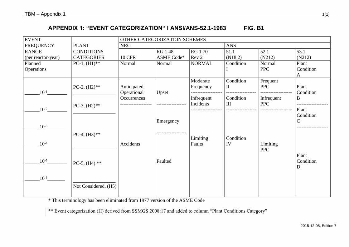
TBM – Appendix 1 1(1)
2015-12-08, Edition 7
APPENDIX 1: “EVENT CATEGORIZATION“ I ANSI/ANS-52.1-1983 FIG. B1
EVENT OTHER CATEGORIZATION SCHEMES
FREQUENCY PLANT NRC ANS
RANGE
(per reactor-year)
CONDITIONS
CATEGORIES
10 CFR
RG 1.48
ASME Code*
RG 1.70
Rev 2
51.1
(N18.2)
52.1
(N212)
53.1
(N212)
Planned
Operations
PC-1, (H1)** Normal Normal NORMAL Condition
I
Normal
PPC
Plant
Condition
A
______10-1________
______10-2________
______10-3_______
______10-4________
______10-5________
______10-6_______
PC-2, (H2)**
_________________
PC-3, (H2)**
_________________
PC-4, (H3)**
_________________
PC-5, (H4) **
_________________
Not Considered, (H5)
Anticipated
Operational
Occurrences
-------------------
Accidents
Upset
------------------
Emergency
------------------
Faulted
Moderate
Frequency
-------------------
Infrequent
Incidents
-------------------
Limiting
Faults
Condition
II
------------------
Condition
III
------------------
Condition
IV
Frequent
PPC
-------------------
Infrequent
PPC
-------------------
Limiting
PPC
Plant
Condition
B
-------------------
Plant
Condition
C
-------------------
Plant
Condition
D
* This terminology has been eliminated from 1977 version of the ASME Code
** Event categorization (H) derived from SSMGS 2008:17 and added to column “Plant Conditions Category”
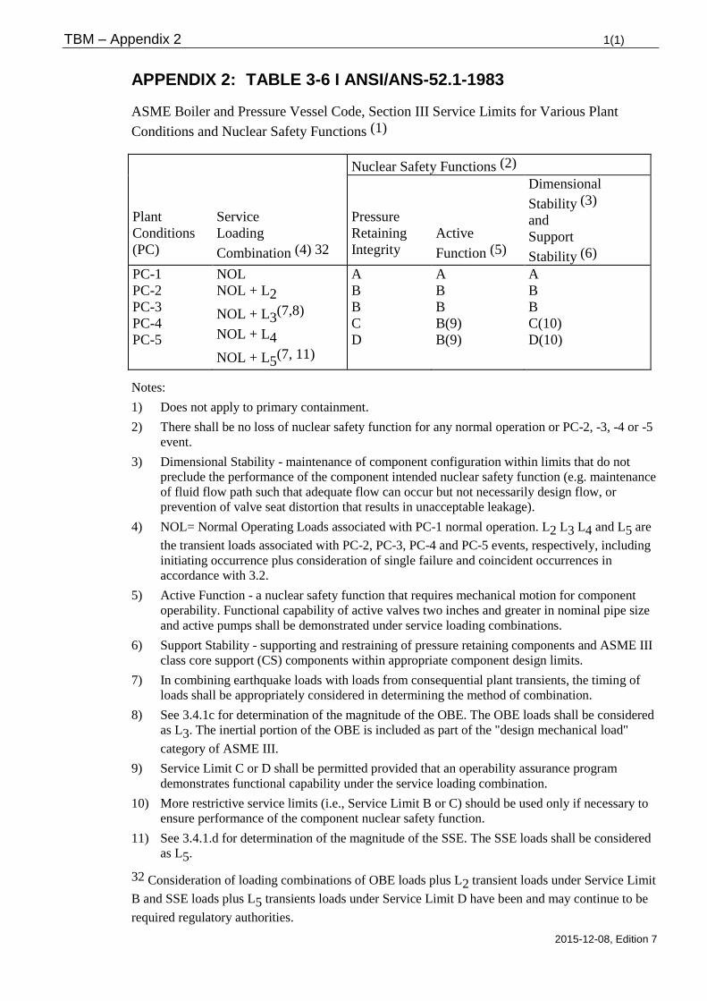
TBM – Appendix 2 1(1)
2015-12-08, Edition 7
APPENDIX 2: TABLE 3-6 I ANSI/ANS-52.1-1983
ASME Boiler and Pressure Vessel Code, Section III Service Limits for Various Plant
Conditions and Nuclear Safety Functions (1)
Nuclear Safety Functions (2)
Plant
Conditions
(PC)
Service
Loading
Combination (4) 32
Pressure
Retaining
Integrity
Active
Function (5)
Dimensional
Stability (3)
and
Support
Stability (6)
PC-1
PC-2
PC-3
PC-4
PC-5
NOL
NOL + L2
NOL + L3(7,8)
NOL + L4
NOL + L5(7, 11)
A
B
B
C
D
A
B
B
B(9)
B(9)
A
B
B
C(10)
D(10)
Notes:
1) Does not apply to primary containment.
2) There shall be no loss of nuclear safety function for any normal operation or PC-2, -3, -4 or -5
event.
3) Dimensional Stability - maintenance of component configuration within limits that do not
preclude the performance of the component intended nuclear safety function (e.g. maintenance
of fluid flow path such that adequate flow can occur but not necessarily design flow, or
prevention of valve seat distortion that results in unacceptable leakage).
4) NOL= Normal Operating Loads associated with PC-1 normal operation. L2 L3 L4 and L5 are
the transient loads associated with PC-2, PC-3, PC-4 and PC-5 events, respectively, including
initiating occurrence plus consideration of single failure and coincident occurrences in
accordance with 3.2.
5) Active Function - a nuclear safety function that requires mechanical motion for component
operability. Functional capability of active valves two inches and greater in nominal pipe size
and active pumps shall be demonstrated under service loading combinations.
6) Support Stability - supporting and restraining of pressure retaining components and ASME III
class core support (CS) components within appropriate component design limits.
7) In combining earthquake loads with loads from consequential plant transients, the timing of
loads shall be appropriately considered in determining the method of combination.
8) See 3.4.1c for determination of the magnitude of the OBE. The OBE loads shall be considered
as L3. The inertial portion of the OBE is included as part of the "design mechanical load"
category of ASME III.
9) Service Limit C or D shall be permitted provided that an operability assurance program
demonstrates functional capability under the service loading combination.
10) More restrictive service limits (i.e., Service Limit B or C) should be used only if necessary to
ensure performance of the component nuclear safety function.
11) See 3.4.1.d for determination of the magnitude of the SSE. The SSE loads shall be considered
as L5.
32 Consideration of loading combinations of OBE loads plus L2 transient loads under Service Limit
B and SSE loads plus L5 transients loads under Service Limit D have been and may continue to be
required regulatory authorities.
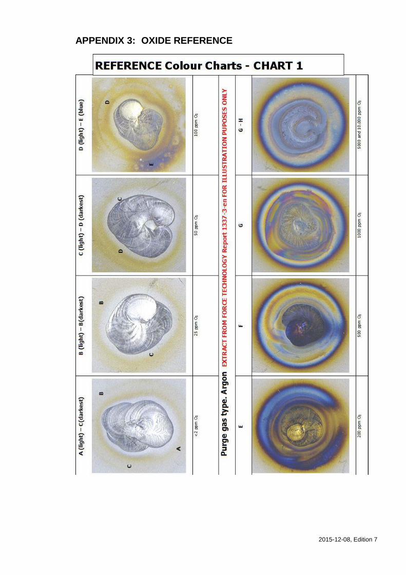
2015-12-08, Edition 7
APPENDIX 3: OXIDE REFERENCE
2015-12-08, Edition 7
APPENDIX 4, TIGHTNESS CLASSIFICATION
The definition is for BWR, the reader must interpret in PWR.
Three tightness classes:
P (Primary)
S (Secondary)
K (Conventional)
Pressure retaining systems and ventilation systems are assigned tightness class.
Components are tightness classified in order to give priority to the measures to keep tight
system. The components where the risk/consequences for leakage is largest, receives the
highest tightness class (P). This classification is not governed by any code, it was rather
established by the initial supplier ASEA-ATOM.
DIVISION INTO TIGHTNESS CLASSES
The tightness class division is evident from the respective plant’s classification lists.
Tightness requirements and acceptance criteria for the respective tightness class is specified
in TBM (PAKT). Ventilation systems are according to certain rules in TBV chapter 2
divided in tightness class S or K.
TIGHTNESS CLASS P MEDIA WITH HIGH RADIOACTIVE CONTENT
System parts belonging to RCPB (Reactor Coolant Pressure Boundary).
Pressurised system parts containing reactor water that are located before ion exchanger.
TIGHTNESS CLASS S MEDIA WITH LOW RADIOACTIVE CONTENT
Pressurised system parts containing reactor water that are located after ion exchanger.
System parts connected to system parts belonging to class P. The interface is normally
constitutes of the first normally closed valve or closing device, when the flow runs from
class P to class S, or via the first valve possible to close when the flow runs from class S
to class P.
System parts up to the first normally closed valve or closing device when the flow runs
from class S to class K, or up to the first valve possible to close when the flow runs from
class K to class S.
System or component that constitutes a part of the reactor containment.
Parts of the radioactive waste system and waste gas system which contain highly
radioactive medium.
TIGHTNESS CLASS K
Pressure retaining system parts not belonging to tightness class P and S.
2015-12-08, Edition 7
EXAMPLES OF SEALING ARRANGEMENTS – PROCESS SYSTEMS
The below summary lists examples of sealing arrangements for flanges, valves, pumps and
atmospheric storage tanks, dependant of tightness class.
TIGHTNESS CLASS P
Flanges with spiral wound gasket in groove or with inner support ring. Suitable built in
metallic seal may also be used. For dimensions >DN50 (2” NPS) may the connection be
prepared for seal welding.
For piping are threaded fittings not permitted inside the reactor building and normally nor
outside of the reactor building.
Globe valves < DN 65 (2 ½” NPS) shall be bellow sealed. Globe valves > DN 65 and other
valves with stem shall be equipped with double stuffing box and intermediate drainage.
Bolted bonnet shall for > DN 50 (2” NPS) be furnished with lips for seal welding. Spiral
wound gaskets are preferred.
Pumps shall be fully encased and designed without shaft seal.
In the cases where operation pressure is below 2 MPa, the seal design is regarded as
tightness class S.
TIGHTNESS CLASS S
Flanges shall be designed with spiral wound gasket in groove or gasket with inner and outer
support ring. Simple flat gasket may be used if operating pressure is below 2 MPa.
Threaded pipe fittings can be used in drainage- and instrumentation piping with > DN 25
(1” NPS). For such cases there shall be an isolation valve installed between the pressurised
system and the first threaded pipe fitting.
Valves with single with a single stuffing box may be used.
Bolted bonnet can be designed with spiral wound gasket in groove, or built in plain gasket
or O-rings. For valves < 50 (2” NPS) may metallic O-rings or metallic seals be used. Self
sealing bonnets with double seals and intermediate drainage shall not be used at stainless
valves. Sealing arrangements where movement or rotation between sealing surfaces occurs
at compression should be avoided.
Pumps shall have encased leakage collection.
For atmospheric storage tanks may plain flat gasket or suitable built-in O-rings be used.
In the cases where the pressure is below 1 bar, regardless of temperature, the sealing
arrangements is regarded as for tightness class K. Also in the case where the temperature
does not exceed 100°C, regardless of pressure, the sealing arrangements is regarded as for
tightness class K.
TIGHTNESS CLASS K
Conventional design is acceptable. Threaded pipe fittings may be used in piping < DN 25
(1” NPS).